CN201220254Y - Grading stamping mould with precise initial location - Google Patents
Grading stamping mould with precise initial location Download PDFInfo
- Publication number
- CN201220254Y CN201220254Y CNU2008201157325U CN200820115732U CN201220254Y CN 201220254 Y CN201220254 Y CN 201220254Y CN U2008201157325 U CNU2008201157325 U CN U2008201157325U CN 200820115732 U CN200820115732 U CN 200820115732U CN 201220254 Y CN201220254 Y CN 201220254Y
- Authority
- CN
- China
- Prior art keywords
- briquetting
- sheet material
- locating piece
- material spare
- guide rail
- Prior art date
- Legal status (The legal status is an assumption and is not a legal conclusion. Google has not performed a legal analysis and makes no representation as to the accuracy of the status listed.)
- Expired - Fee Related
Links
Images


Abstract
The utility model discloses a progressive stamping die with accurate initial positioning, which comprises a concave die and a male die, wherein guide rails and a fine positioning device are fixed on a concave die fixing plate, the fine positioning device comprises a pressing block (6) and a positioning block (2), wherein the pressing block (6) is fixed on a stripper plate (7) of the male die, a guide groove being perpendicular to a sheet part positioning groove and matched with the positioning block (2) is arranged on a guide rail (5), the positioning block (2) is arranged in the guide groove, mutually inclined surfaces (12) are arranged on the pressing block (6) and the positioning block (2), the positioning block (2) is pushed to the sheet part positioning groove by the pressing block (6) through the inclined surfaces, the sheet part is closely stuck on the other guide rail, therefore, the clearance between the sheet part and the guide rail is eliminated, and the positioning accuracy is improved.
Description
Technical field:
The utility model relates to a kind of progressive stamping mould that is used for being fit to the lead frame punching press, specifically a kind of progressive stamping mould for the treatment of pressing sheet material spare positioning accuracy that improves.
Background technology:
For sheet material spare,, in progressive die, want some steps just can finish such as the punching production of lead frame band.An important problem is located exactly in the progressive stamping mould, and each step all will accurately locate when producing, and could guarantee the precision of punching press.A kind of method commonly used is exactly to go out locating hole earlier on sheet material, and the locating pin that cooperates with locating hole is set on the mould, with the location of locating pin realization to product.But new problem has just had, and how punching out accurately goes out locating hole on sheet material spare, guarantees the position of locating hole on stock layout.To be solved in the utility model is exactly this problem.
Summary of the invention:
The utility model provides a kind of progressive stamping mould of positioning accuracy just that improves, and can improve positioning accuracy.
The utility model is achieved in that and comprises die, punch, be fixed with two guide rails that band is just located on the die block, gap between two guide rails is a sheet material spare locating slot, it is characterized in that: further comprising at least two to sheet material spare accurate positioning device, this device is made up of briquetting and locating piece, briquetting is fixed on the stripper of punch, a guide rail is provided with the gathering sill that with locating piece cooperate vertical with sheet material spare locating slot, locating piece is arranged in the described gathering sill, the inclined-plane that cooperatively interacts is arranged on briquetting and the locating piece, when matched moulds, briquetting promotes locating piece by the inclined-plane and advances in sheet material spare locating slot, push sheet material spare to the opposite side guide rail,, so just can improve positioning accuracy to eliminate the gap between sheet material spare and the guide rail.
In order to prevent way rub, improve its service life, described locating piece adopts wear-resisting carbide alloy to make, and is inlaid with the wear-resisting abaculus that Hardmetal materials is made with sheet material spare contact site on another guide rail corresponding with the location pushing block.
Regulate the pressure of locating piece for convenience to sheet material spare, stripper is provided with by the compression spring and regulates the briquetting buffer unit that bolt is formed, have the briquetting installing hole on the stripper, the briquetting upper end has and regulates spiral shell and joins the screw that bolt closes, regulate bolt briquetting is fixed in the installing hole, the compression spring is located between briquetting and the fixation clip.By regulating bolt, can regulating spring power.
Locating piece is advanced by guide rail one thruster the utility model when the matched moulds by adopting, sheet material spare is adjacent on another guide rail, thereby eliminated the gap between sheet material spare and the guide rail, thereby improved positioning accuracy, and bear pushing block pressure position, location on locating piece and the opposite side guide rail and make by carbide alloy, precision is high and not easy to wear.Reload buffer device on the briquetting makes locating piece to raw material, and especially the damage of thin material is little, and regulates more convenient.
Description of drawings:
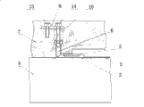
Fig. 1 is the utility model structural representation when die opening state.
Fig. 2 is the utility model structural representation when the matched moulds state.
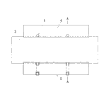
Fig. 3 is the plan view during the pushing block work of location when full mould state.
Fig. 4 is along A-A line profile among Fig. 3.
The specific embodiment:
The utility model is provided with two to sheet material spare accurate positioning device, this accurate positioning device is made up of briquetting 6 and locating piece 2, structure as depicted in figs. 1 and 2, have the briquetting installing hole on the stripper 7 of punch, the briquetting buffer unit is made up of compression spring 10 and adjusting bolt 14, briquetting 6 upper ends have and regulate the screw that bolt 14 cooperates, pressing plate 8 is fixed on the stripper 7 by bolt 13, regulating bolt 14 is fixed on briquetting 6 in the installing hole, compression spring 10 is located between briquetting and the pressing plate, briquetting 6 lower ends have with locating piece 2 on the inclined-plane 12 that cooperatively interacts.
Be fixed with the pair of guide rails 4,5 that sheet material spare 3 is just located on the die block 9, Fig. 1 and Fig. 2 middle guide 4 do not draw.Guide rail cooperates as shown in Figure 3 with sheet material spare, and the gap between two guide rails 4,5 is a sheet material spare locating slot, and sheet material spare 3 is passed through by the locating slot between guide rail 4 and 5, and with guide rail 4,5 certain clearance is arranged.Guide rail 4 is provided with the gathering sill that with locating piece 2 cooperate vertical with sheet material spare locating slot, locating piece 2 is arranged in the gathering sill, there is the inclined-plane 12 that cooperates with inclined-plane, briquetting 6 lower end locating piece 2 rear ends, when matched moulds, briquetting 6 promotes locating piece 2 by inclined-plane 12 and advances in sheet material spare locating slot, and sheet material spare 3 is pressed on the opposite side guide rail 4.Locating piece 2 adopts wear-resisting carbide alloy to make, and is inlaid with the wear-resisting abaculus 1 that Hardmetal materials is made with sheet material spare contact site on another guide rail 4 corresponding with locating piece 2.
When die opening state, as shown in Figure 1, briquetting 6 does not contact with locating piece 2, and locating piece 2 has certain activity in the horizontal direction, with sheet material spare certain clearance 11 is arranged, and sheet material spare 3 can freely enter mould.
When the matched moulds state, as shown in Figure 2, spring 10 is given 6 one downward power of briquetting, and the inclined-plane by briquetting 6, and masterpiece is used on the locating piece 2, forces it to do horizontal movement, and sheet material spare 3 is shifted onto with till wear-resisting abaculus 1 contacts.If power is big, the edge of sheet material spare 3 may arch upward because of the power that is subjected to level; Power is little, and possible sheet material spare 3 can not contact with wear-resisting abaculus 1, does not reach the effect of location.By regulating the bolt 14 that briquetting 6 links to each other with pressing plate 8, can regulate the size of this power, reach desirable effect.
Claims (3)
1, just locate accurate progressive stamping mould, comprise die, punch, be fixed with two guide rails [4 that sheet material spare [3] is just located on the die block, 5], gap between two guide rails is a sheet material spare locating slot, it is characterized in that: further comprising at least two to sheet material spare accurate positioning device, this device is made up of briquetting [6] and locating piece [2], briquetting [6] is fixed on the stripper [7] of punch, guide rail [5] is provided with the gathering sill that with locating piece [2] cooperate vertical with sheet material spare locating slot, locating piece [2] is arranged in the described gathering sill, the inclined-plane [12] that cooperatively interacts is arranged on briquetting [6] and the locating piece [2], when matched moulds, briquetting [6] promotes locating piece [2] by the inclined-plane and advances in sheet material spare locating slot.
2, the accurate progressive stamping mould in location just according to claim 1, it is characterized in that: described locating piece [2] adopts wear-resisting carbide alloy to make, and the guide rail [4] corresponding with locating piece [2] gone up and sheet material spare contact site is inlaid with the wear-resisting abaculus [1] that Hardmetal materials is made.
3, the accurate progressive stamping mould in location just according to claim 1 and 2, it is characterized in that: stripper [7] is provided with by compression spring [10] and regulates the briquetting buffer unit that bolt [14] is formed, stripper has the briquetting installing hole on [7], the briquetting upper end has and regulates the screw that bolt cooperates, regulate bolt [14] briquetting [6] is fixed in the installing hole, compression spring [10] is located between briquetting [6] and the pressing plate [8].
Priority Applications (1)
| Application Number | Priority Date | Filing Date | Title |
|---|---|---|---|
| CNU2008201157325U CN201220254Y (en) | 2008-06-26 | 2008-06-26 | Grading stamping mould with precise initial location |
Applications Claiming Priority (1)
| Application Number | Priority Date | Filing Date | Title |
|---|---|---|---|
| CNU2008201157325U CN201220254Y (en) | 2008-06-26 | 2008-06-26 | Grading stamping mould with precise initial location |
Publications (1)
| Publication Number | Publication Date |
|---|---|
| CN201220254Y true CN201220254Y (en) | 2009-04-15 |
Family
ID=40573774
Family Applications (1)
| Application Number | Title | Priority Date | Filing Date |
|---|---|---|---|
| CNU2008201157325U Expired - Fee Related CN201220254Y (en) | 2008-06-26 | 2008-06-26 | Grading stamping mould with precise initial location |
Country Status (1)
| Country | Link |
|---|---|
| CN (1) | CN201220254Y (en) |
Cited By (5)
| Publication number | Priority date | Publication date | Assignee | Title |
|---|---|---|---|---|
| CN102672049A (en) * | 2012-05-23 | 2012-09-19 | 顺德工业(江苏)有限公司 | Die for precision stamping of boards |
| CN105102192A (en) * | 2012-10-04 | 2015-11-25 | 格罗兹-贝克特公司 | Method and tool unit for setting punching gap |
| CN105538253A (en) * | 2015-12-08 | 2016-05-04 | 厦门市万家灿灯具有限公司 | Workbench device used for panel processing and capable of achieving abrasion resistance and use method thereof |
| CN105643676A (en) * | 2014-12-02 | 2016-06-08 | 阜南县方柳工艺品有限公司 | Automatic cutting machine for furniture panel |
| CN106623630A (en) * | 2016-12-20 | 2017-05-10 | 柳州通为机械有限公司 | High-positioning-precision stamping die for automobile parts |
-
2008
- 2008-06-26 CN CNU2008201157325U patent/CN201220254Y/en not_active Expired - Fee Related
Cited By (6)
| Publication number | Priority date | Publication date | Assignee | Title |
|---|---|---|---|---|
| CN102672049A (en) * | 2012-05-23 | 2012-09-19 | 顺德工业(江苏)有限公司 | Die for precision stamping of boards |
| CN105102192A (en) * | 2012-10-04 | 2015-11-25 | 格罗兹-贝克特公司 | Method and tool unit for setting punching gap |
| US9796103B2 (en) | 2012-10-04 | 2017-10-24 | Groz-Beckert Kg | Method and tool unit for setting a punching gap |
| CN105643676A (en) * | 2014-12-02 | 2016-06-08 | 阜南县方柳工艺品有限公司 | Automatic cutting machine for furniture panel |
| CN105538253A (en) * | 2015-12-08 | 2016-05-04 | 厦门市万家灿灯具有限公司 | Workbench device used for panel processing and capable of achieving abrasion resistance and use method thereof |
| CN106623630A (en) * | 2016-12-20 | 2017-05-10 | 柳州通为机械有限公司 | High-positioning-precision stamping die for automobile parts |
Similar Documents
| Publication | Publication Date | Title |
|---|---|---|
| CN201220254Y (en) | Grading stamping mould with precise initial location | |
| CN1327984C (en) | Punching-pressing composite mould | |
| CN1327985C (en) | Punching-pressing composite mould | |
| CN100427239C (en) | Composite cold stamping mold | |
| CN103962453A (en) | Compound die for punching counter bores and bosses of plate | |
| CN201644636U (en) | Elastic part progressive die for electronic scale | |
| CN201244630Y (en) | Material-pulling device in progressive die | |
| CN201511075U (en) | Floating type ultrashort die for stamping small hole on thick sheet | |
| CN102416422A (en) | Lever mechanism for smooth transfer mold bending and reshaping process | |
| CN207170710U (en) | One kind transmits mould stripper plate slide block structure on mould | |
| CN204182800U (en) | A kind of compound punching structure for punch level progressive die | |
| CN107377779A (en) | One kind transmits mould stripper plate slide block structure on mould | |
| CN102284605A (en) | Side positioning stamping method and stamping mould thereof | |
| CN202199660U (en) | Nitrogen spring type composite trimming device | |
| CN107030193B (en) | Drawing die with punch mechanism | |
| CN102189216B (en) | Rivet punching die | |
| CN203900226U (en) | Punching die | |
| CN204262156U (en) | Wedge mechanism | |
| CN203862829U (en) | Composite die for punching countersinks and convex hulls on plates | |
| CN210080508U (en) | Buffering type traceless bending precision die | |
| CN203459546U (en) | Forming and shaping die structure | |
| CN108555153B (en) | Stamping die with trade core structure | |
| CN208894970U (en) | A kind of stamping die of hexagonal nuts workpiece | |
| CN208555661U (en) | Formed punch locking member and punching equipment comprising it | |
| CN215032849U (en) | Die carrier for QDC hardware die |
Legal Events
| Date | Code | Title | Description |
|---|---|---|---|
| C14 | Grant of patent or utility model | ||
| GR01 | Patent grant | ||
| C17 | Cessation of patent right | ||
| CF01 | Termination of patent right due to non-payment of annual fee |
Granted publication date: 20090415 Termination date: 20110626 |