CN1770552A - Antenna-embedded laminated glass and method for preparing the same - Google Patents
Antenna-embedded laminated glass and method for preparing the same Download PDFInfo
- Publication number
- CN1770552A CN1770552A CNA2005101192654A CN200510119265A CN1770552A CN 1770552 A CN1770552 A CN 1770552A CN A2005101192654 A CNA2005101192654 A CN A2005101192654A CN 200510119265 A CN200510119265 A CN 200510119265A CN 1770552 A CN1770552 A CN 1770552A
- Authority
- CN
- China
- Prior art keywords
- antenna
- glass
- conductive strips
- sheet glass
- sheet
- Prior art date
- Legal status (The legal status is an assumption and is not a legal conclusion. Google has not performed a legal analysis and makes no representation as to the accuracy of the status listed.)
- Pending
Links
- 239000005340 laminated glass Substances 0.000 title claims abstract description 45
- 238000000034 method Methods 0.000 title claims abstract description 37
- 239000011521 glass Substances 0.000 claims abstract description 18
- 239000005357 flat glass Substances 0.000 claims description 109
- 239000002390 adhesive tape Substances 0.000 claims description 28
- 239000012528 membrane Substances 0.000 claims description 23
- 238000004519 manufacturing process Methods 0.000 claims description 12
- 238000003475 lamination Methods 0.000 claims description 10
- 229920005989 resin Polymers 0.000 claims description 6
- 239000011347 resin Substances 0.000 claims description 6
- 239000000853 adhesive Substances 0.000 claims description 3
- 230000001070 adhesive effect Effects 0.000 claims description 3
- 239000000463 material Substances 0.000 description 58
- 239000010410 layer Substances 0.000 description 26
- 230000008569 process Effects 0.000 description 20
- 238000006073 displacement reaction Methods 0.000 description 10
- 241001212149 Cathetus Species 0.000 description 8
- 239000012790 adhesive layer Substances 0.000 description 8
- 238000007639 printing Methods 0.000 description 7
- 239000011241 protective layer Substances 0.000 description 6
- 230000008602 contraction Effects 0.000 description 5
- 238000004080 punching Methods 0.000 description 5
- 239000002994 raw material Substances 0.000 description 5
- 230000008878 coupling Effects 0.000 description 3
- 238000010168 coupling process Methods 0.000 description 3
- 238000005859 coupling reaction Methods 0.000 description 3
- 238000010586 diagram Methods 0.000 description 3
- 238000010438 heat treatment Methods 0.000 description 3
- 229920002037 poly(vinyl butyral) polymer Polymers 0.000 description 3
- 238000003466 welding Methods 0.000 description 3
- 238000000137 annealing Methods 0.000 description 2
- 230000008859 change Effects 0.000 description 2
- 238000004140 cleaning Methods 0.000 description 2
- 238000005520 cutting process Methods 0.000 description 2
- 239000000047 product Substances 0.000 description 2
- 238000007652 sheet-forming process Methods 0.000 description 2
- 239000002002 slurry Substances 0.000 description 2
- 230000000007 visual effect Effects 0.000 description 2
- RYGMFSIKBFXOCR-UHFFFAOYSA-N Copper Chemical compound [Cu] RYGMFSIKBFXOCR-UHFFFAOYSA-N 0.000 description 1
- NIXOWILDQLNWCW-UHFFFAOYSA-N acrylic acid group Chemical group C(C=C)(=O)O NIXOWILDQLNWCW-UHFFFAOYSA-N 0.000 description 1
- 230000008901 benefit Effects 0.000 description 1
- 230000000903 blocking effect Effects 0.000 description 1
- 239000007795 chemical reaction product Substances 0.000 description 1
- 239000004020 conductor Substances 0.000 description 1
- 229910052802 copper Inorganic materials 0.000 description 1
- 239000010949 copper Substances 0.000 description 1
- 238000001035 drying Methods 0.000 description 1
- 230000000694 effects Effects 0.000 description 1
- 230000005611 electricity Effects 0.000 description 1
- 238000005516 engineering process Methods 0.000 description 1
- 230000005484 gravity Effects 0.000 description 1
- 238000009413 insulation Methods 0.000 description 1
- 230000013011 mating Effects 0.000 description 1
- 238000012986 modification Methods 0.000 description 1
- 230000004048 modification Effects 0.000 description 1
- 229920006267 polyester film Polymers 0.000 description 1
- 238000002310 reflectometry Methods 0.000 description 1
- 238000005096 rolling process Methods 0.000 description 1
- 230000008646 thermal stress Effects 0.000 description 1
- 238000009966 trimming Methods 0.000 description 1
- 239000002023 wood Substances 0.000 description 1
Images


Classifications
-
- C—CHEMISTRY; METALLURGY
- C03—GLASS; MINERAL OR SLAG WOOL
- C03C—CHEMICAL COMPOSITION OF GLASSES, GLAZES OR VITREOUS ENAMELS; SURFACE TREATMENT OF GLASS; SURFACE TREATMENT OF FIBRES OR FILAMENTS MADE FROM GLASS, MINERALS OR SLAGS; JOINING GLASS TO GLASS OR OTHER MATERIALS
- C03C27/00—Joining pieces of glass to pieces of other inorganic material; Joining glass to glass other than by fusing
- C03C27/06—Joining glass to glass by processes other than fusing
- C03C27/10—Joining glass to glass by processes other than fusing with the aid of adhesive specially adapted for that purpose
-
- H—ELECTRICITY
- H01—ELECTRIC ELEMENTS
- H01Q—ANTENNAS, i.e. RADIO AERIALS
- H01Q1/00—Details of, or arrangements associated with, antennas
- H01Q1/36—Structural form of radiating elements, e.g. cone, spiral, umbrella; Particular materials used therewith
- H01Q1/38—Structural form of radiating elements, e.g. cone, spiral, umbrella; Particular materials used therewith formed by a conductive layer on an insulating support
-
- B—PERFORMING OPERATIONS; TRANSPORTING
- B32—LAYERED PRODUCTS
- B32B—LAYERED PRODUCTS, i.e. PRODUCTS BUILT-UP OF STRATA OF FLAT OR NON-FLAT, e.g. CELLULAR OR HONEYCOMB, FORM
- B32B17/00—Layered products essentially comprising sheet glass, or glass, slag, or like fibres
- B32B17/06—Layered products essentially comprising sheet glass, or glass, slag, or like fibres comprising glass as the main or only constituent of a layer, next to another layer of a specific material
- B32B17/10—Layered products essentially comprising sheet glass, or glass, slag, or like fibres comprising glass as the main or only constituent of a layer, next to another layer of a specific material of synthetic resin
- B32B17/10005—Layered products essentially comprising sheet glass, or glass, slag, or like fibres comprising glass as the main or only constituent of a layer, next to another layer of a specific material of synthetic resin laminated safety glass or glazing
- B32B17/10009—Layered products essentially comprising sheet glass, or glass, slag, or like fibres comprising glass as the main or only constituent of a layer, next to another layer of a specific material of synthetic resin laminated safety glass or glazing characterized by the number, the constitution or treatment of glass sheets
- B32B17/10036—Layered products essentially comprising sheet glass, or glass, slag, or like fibres comprising glass as the main or only constituent of a layer, next to another layer of a specific material of synthetic resin laminated safety glass or glazing characterized by the number, the constitution or treatment of glass sheets comprising two outer glass sheets
-
- B—PERFORMING OPERATIONS; TRANSPORTING
- B32—LAYERED PRODUCTS
- B32B—LAYERED PRODUCTS, i.e. PRODUCTS BUILT-UP OF STRATA OF FLAT OR NON-FLAT, e.g. CELLULAR OR HONEYCOMB, FORM
- B32B17/00—Layered products essentially comprising sheet glass, or glass, slag, or like fibres
- B32B17/06—Layered products essentially comprising sheet glass, or glass, slag, or like fibres comprising glass as the main or only constituent of a layer, next to another layer of a specific material
- B32B17/10—Layered products essentially comprising sheet glass, or glass, slag, or like fibres comprising glass as the main or only constituent of a layer, next to another layer of a specific material of synthetic resin
- B32B17/10005—Layered products essentially comprising sheet glass, or glass, slag, or like fibres comprising glass as the main or only constituent of a layer, next to another layer of a specific material of synthetic resin laminated safety glass or glazing
- B32B17/1055—Layered products essentially comprising sheet glass, or glass, slag, or like fibres comprising glass as the main or only constituent of a layer, next to another layer of a specific material of synthetic resin laminated safety glass or glazing characterized by the resin layer, i.e. interlayer
- B32B17/10761—Layered products essentially comprising sheet glass, or glass, slag, or like fibres comprising glass as the main or only constituent of a layer, next to another layer of a specific material of synthetic resin laminated safety glass or glazing characterized by the resin layer, i.e. interlayer containing vinyl acetal
-
- H—ELECTRICITY
- H01—ELECTRIC ELEMENTS
- H01Q—ANTENNAS, i.e. RADIO AERIALS
- H01Q1/00—Details of, or arrangements associated with, antennas
- H01Q1/12—Supports; Mounting means
- H01Q1/1271—Supports; Mounting means for mounting on windscreens
-
- H—ELECTRICITY
- H01—ELECTRIC ELEMENTS
- H01Q—ANTENNAS, i.e. RADIO AERIALS
- H01Q1/00—Details of, or arrangements associated with, antennas
- H01Q1/12—Supports; Mounting means
- H01Q1/1271—Supports; Mounting means for mounting on windscreens
- H01Q1/1285—Supports; Mounting means for mounting on windscreens with capacitive feeding through the windscreen
-
- H—ELECTRICITY
- H01—ELECTRIC ELEMENTS
- H01Q—ANTENNAS, i.e. RADIO AERIALS
- H01Q1/00—Details of, or arrangements associated with, antennas
- H01Q1/40—Radiating elements coated with or embedded in protective material
Abstract
The present invention provides a method for preparing an antenna-embedded laminated glass with an antenna element sealed between glass sheets, which is characterized to comprise forming two or more glass sheets forming the laminated glass; bonding a transfer film on a surface of one of the glass sheets by a bonding strip, the transfer film including the bonding strip and a conductive strip forming the antenna element; and press-bonding the glass sheets, through an intermediate film, to the surface of the one glass sheet with the transfer film bonded thereto.
Description
Technical field
The present invention relates between sheet glass, enclose the laminated glass of the flush antenna of antenna element, and manufacture method.
Background technology
Known so far a kind of antenna sheet material, this sheet material comprise conductive strips that are used for antenna element and the adhesive layer (seeing for example JP-A-2001-119219) that places on the base sheet.Use adhesive layer that this antenna sheet material is bonded on the surface of sheet glass, this antenna sheet material can play glass antenna.
In practicality, this antenna sheet material is fixed on the glass sheet surface.From this view point, when this antenna sheet material being bonded in the inner surface of vehicle front windshield for example, need cover described conductive strips with transparent protective layer.Settling protective layer is in order to prevent that conductive strips are damaged or owing to external force is separated.In some cases, because the refractive index of described protective layer is different with sheet glass, and this protective layer covered the zone of sheet glass broad, so fixing between the sheet glass of antenna sheet material at protective layer with on it, can see the line of demarcation.Owing to these reasons, this antenna sheet material is not attractive in appearance, and can influence driver's the visual field.
And between sheet glass, enclosed in the laminated glass of flush antenna of antenna element (seeing for example JP-A-2-82701); antenna element is subjected to the protection of sheet glass; even the windshield that the laminated glass of this flush antenna is used for vehicle also not for example in a zone except using antenna element, also used the outward appearance that protective layer caused problem not attractive in appearance and so on.
The laminated glass of this flush antenna is classified as the printing type, because will conduct electricity slurries (paste) with required pattern, on the inner surface (matching surface) of sheet glass, thereby forms antenna element; And intermediate coat is classified as the embedding type, wherein flush antenna wire (wire) in the intermediate coat between sheet glass (usually by being made by polyvinyl butyral resin).
Above-mentioned printing class can't solve problems such as appearance poor, and this is because antenna pattern needs wide live width, just can guarantee because the required antenna performance that big wire resistance forms.
Based on this point, because the antenna wire of minor diameter can embed intermediate coat, it is useful to problems such as solution appearance poor that above-mentioned intermediate coat embeds type.
Yet, embed type for above-mentioned intermediate coat, wherein embed intermediate coat that antenna wire is arranged and in bonding and so on the heat treatment process of exerting pressure, can expand or shrink, so that antenna wire is subjected to displacement.This is because laminated glass is by adding one deck intermediate coat between two sheet glass sheets, exerts pressure bonding then and heat treatment is made.The trend of this displacement brings problem can for the performance of antenna.In addition, because the trend of this displacement is the principal element that causes the antenna pattern change in location in each end product, brought problem therefore also for stable antenna performance.
A target of the present invention provides the laminated glass and the manufacture method thereof of flush antenna, and this glass is difficult for producing the displacement of antenna pattern in process of production, and has good surface appearance etc.
Summary of the invention
In order to address the above problem, according to a first aspect of the invention, a kind of method of making the laminated glass of flush antenna is provided, has enclosed a plurality of sheet glass of antenna element thereby this laminated glass comprises being fixed together between adjacent glass sheets with intermediate coat, described intermediate coat comprises resin; This method comprises the sheet glass that forms the multi-disc curved shape; Sheet glass, antenna element and intermediate coat are carried out lamination, thus the cambium layer laminated structure; Described intermediate coat is inserted between the adjacent sheet glass, exerts pressure these sheet glass bonding; Wherein said lamination step comprises by using the bonding adhesive transfer film that brings, surface at least one sheet glass sheet forms conductive strips, thus the cambium layer laminated structure, and described transfer membrane comprises described adhesive tape and conductive strips, described conductive strips form antenna element, and described surface is facing to intermediate coat.
In this aspect, described conductive strips can comprise the straight line portion that forms required pattern, and its live width (W) satisfies relational expression 0.15≤W≤0.4 millimeter.Transfer membrane has bonding surface thereon on the convex surface of at least one sheet glass sheet of curvature.
According to a further aspect in the invention, provide a kind of laminated glass of flush antenna, enclosed a plurality of sheet glass of antenna element thereby this laminated glass comprises being fixed together between adjacent glass sheets with intermediate coat, described intermediate coat comprises resin; Described antenna element comprises with adhesive tape and is fixed on the conductive strips on a slice adjacent glass sheets surface at least that described surface is facing to intermediate coat.
Explain that according to the present invention, bonding its middle Method for bonding of exerting pressure that accompanies the sheet glass of intermediate coat that is used for exerting pressure can carry out when the conductive strips that will form antenna element with adhesive tape are bonded on the glass sheet surface (matching surface).Therefore, in the adhesion process of exerting pressure, can prevent that antenna element (conductive strips) is subjected to displacement with respect to sheet glass by the expansion or the contraction of intermediate coat, thereby make the laminated glass of flush antenna with high antenna element location precision.When the live width of the conductor belt that forms antenna element is the 0.15-0.4 millimeter, can obtain having the laminated glass of the flush antenna of excellent appearance etc.
Description of drawings
In these figure:
Fig. 1 shows the perspective view that the laminated glass of flush antenna of the present invention is used as an example application of vehicle front windshield;
Fig. 2 shows the flow chart of major part of the laminated glass manufacture method of flush antenna of the present invention, wherein:
AA raw material sheet glass (outer sheet glass)
BB raw material sheet glass (interior sheet glass)
The CC fixed antenna
The DD intermediate coat
The EE laminated glass
S101 cutting and chamfering
S102 cleans with dry
The S103 printing
S104 is overlapping
The S105 hot forming
S106 annealing
S107 separates
S108 cleans with dry
S121 peels off fixture
The S122 location is with fixing
S123 peels off diaphragm
S124 handles antenna end portion
S141 cleans
S142 cuts film
The S143 lamination
S144 exerts pressure bonding in advance
S145 handles (master exerts pressure bonding) in autoclave;
Fig. 3 shows the schematic diagram of the antenna sheet material of one embodiment of the present invention;
Fig. 4 is the sectional view along Fig. 3 cathetus A-A;
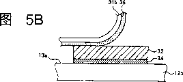
Fig. 5 A and 5B are the schematic diagrames of explanation conductive strips transfer process;
Fig. 6 A is the sectional view along Fig. 3 cathetus A-A, has shown the antenna sheet material of another execution mode among the figure;
Fig. 6 B is the sectional view along Fig. 3 cathetus A-A, has shown the antenna sheet material of another execution mode among the figure;
Fig. 7 is when being presented at antenna sheet material shown in shop drawings 3 and Fig. 4, how to suppress the schematic diagram of transfer membrane material;
Fig. 8 is presented in the laminated glass of the flush antenna that the present invention makes the perspective view of electrode deriving structure first execution mode of antenna element;
Fig. 9 is the sectional view along Fig. 8 cathetus X-X;
Figure 10 is presented in the laminated glass of the flush antenna that the present invention makes the perspective view of electrode deriving structure second execution mode of antenna element;
Figure 11 shows the antenna sheet material corresponding to execution mode shown in Figure 10;
Figure 12 is the sectional view along Figure 10 cathetus X-X.
Embodiment
Below in conjunction with these accompanying drawings the preferred embodiment of the present invention is described.
Fig. 1 shows an example application of the laminated glass of flush antenna of the present invention.Although as being used as the front windshield of vehicle with in the example, this laminated glass also can be used as the side windshield or the rear seat windscreen of vehicle to the laminated glass of flush antenna 10 usually.
It is bonding that the multi-disc sheet glass that therebetween is placed with intermediate coat 14 is exerted pressure, and prepares described laminated glass 10 (see figure 8)s.This intermediate coat can be made by for example polyvinyl butyral resin (PVB).
As hereinafter illustrating, between the sheet glass 12 that forms laminated glass 10, enclosed antenna element 20.Described antenna element 20 can form required pattern as illustrated in fig. 1, and for example receives the electromagnetic wave from TV station or radio station, from the electromagnetic wave of mobile phone, or from the electromagnetic wave of satellite.In this example application, because this antenna element is enclosed between the sheet glass 12, antenna element 20 is subjected to the protection of sheet glass 12.
Fig. 2 is the flow chart of major part that shows the laminated glass manufacture method of flush antenna of the present invention.To describe a kind of situation below, in this case, described laminated glass comprises two sheet glass sheets 12, and when being installed in this laminated glass on the vehicle, the sheet glass that is in the outside is represented with digital 12a, is in inboard sheet glass and represents with digital 12b.
As shown in Figure 2, the present embodiment method that is used for making laminated glass comprises glass sheet forming process 100, conductive strips transfer process 120 and sheet glass lamination process 140.
In glass sheet forming process 100, two tablet raw materials (basic) sheet glass is cut respectively and chamfering step (step 101), and cleaning and drying steps (step 102) processing.In order to cover dazzling light, (step 103) printed in the marginal portion that forms the raw material sheet glass (interior sheet glass) of the sheet glass 12b of inboard in the two tablet raw material sheet glass.Also externally print the marginal portion of sheet glass, and perhaps externally sheet glass and interior sheet glass all print.Then two sheet glass sheets are overlapped each other (step 104) marginal portion of the two sheet glass sheets that overlap each other with frame supported.Next, overlapping like this sheet glass is heated to the temperature that is not less than softening point, it is bent to crooked shape (step 105) by gravity.Then two sheet glass sheets are carried out annealing in process (step 106), again with two sheet glass sheets (step 107) disconnected from each other.Essentially identical sheet glass 12a of surface curvature and 12b have been made like this.Independently to sheet glass 12a with 12b cleans and dry (step 108), again it is changed over to conductive strips transfer process 120 subsequently.
In conductive strips transfer process 120, antenna sheet material 30 is fixed on the outer surface of sheet glass 12b.The outer surface of described sheet glass 12b promptly be preamble described in the outer surface of sheet glass 12b, promptly when sheet glass 12b and sheet glass 12a were carried out lamination, sheet glass 12b faced toward the surface (hereinafter being called " matching surface 13a ") of sheet glass 12a.
As shown in Figure 3, antenna sheet material 30 is the sheet materials with required form.(show along Fig. 3 cathetus A-A sectional view) as shown in Figure 4, this antenna sheet material 30 comprises containing and is used for forming the conductive strips 32 of at least one antenna element 20 and the transfer membrane material of adhesive tape 34.Described conductive strips 32 and adhesive tape 34 are positioned between first separable layer (fixture) 31a and second separable layer (diaphragm) 31b that forms required form.This first separable layer is a fixture, is used for fixing the antenna pattern that is formed by conductive strips 32, till the matching surface 13a that conductive strips 32 and adhesive tape 34 is fixed on sheet glass 12b goes up.Because the transfer membrane material comprises this fixture, this transfer membrane material not only can be handled and fixing conductive strips, but also can prevent that antenna pattern from deforming.The second separable layer is a diaphragm, is used for protecting described conductive strips, till the matching surface 13a that conductive strips 32 and adhesive tape 34 is fixed on sheet glass 12b goes up.Because described transfer membrane material comprises diaphragm, it can prevent that antenna pattern from deforming owing to the external force effect or damage.Put from this, preferably before soon placing described transfer membrane material and be fixed on the matching surface 13b, second separable layer is separated.Between the conductive strips 32 and the second separable layer 31b, has adhesive layer 35.This its segregative bonding force of adhesive layer 35 usefulness is bonded together the conductive strips 32 and the second separable layer 31b.The described first separable layer 31a has the slit 50 that forms in each zone, so that work when lock out operation.
In conductive strips transfer process 120, at first make first separable layer (fixture) 31a separate (step 121), will separate antenna sheet material 30 location of first separable layer then and be bonded on the desired location of sheet glass 12b matching surface 13a (step 122) from antenna sheet material 30.Be bonded in conductive strips 32 on the matching surface 13a of sheet glass 12b with adhesive tape 34 this moment shown in Fig. 5 A.Be bonded together in order to ensure this adhesive tape 34 and matching surface 13a, antenna sheet material 30 can be pressed to the matching surface 13a of sheet glass 12b.
Next, shown in Fig. 5 B, second separable layer (diaphragm) 31b is separated with conductive strips 32 along adhesive layer 35.So just remove the first separable layer 31a and the second separable layer 31b, on the matching surface 13a of sheet glass 12b, only stayed conductive strips 32 and adhesive tape 34.Clearly the bonding force between adhesive layer 35 and the conductive strips 32 will be adjusted to abundant bonding force less than adhesive tape 34.It is in order to prevent that conductive strips 32 from separating with the matching surface 13a of adhesive tape 34 from sheet glass 12b, to prevent from simultaneously when separating the second separable layer 31b conductive strips 32 to be separated with adhesive tape 34 that bonding force is carried out such adjusting.
Then, can handle as required, for example the end portion of antenna element 20 be bent (see figure 8) from the marginal portion of sheet glass 12b, so that with this antenna element 20 (conductive strips 32) (see figure 8) (step 124) that links to each other with electrode 40.
Described antenna sheet material is bonded in after sheet glass 12b goes up when having finished as previously mentioned, next these sheet glass carried out lamination process 140 and handle, promptly sheet glass 12b and sheet glass 12a are carried out lamination.
In sheet glass lamination process 140, with antenna element and the intermediate coat and the sheet glass cambium layer laminated structure that are used for fixing antenna element, intermediate coat is placed between the sheet glass, and it is bonding that sheet glass, antenna element and intermediate coat are exerted pressure, thereby form laminated glass.Specifically, at first intermediate coat is cut into and sheet glass 12a and the essentially identical shape of 12b, it is carried out cleaning step and film cutting step processing (step 141 and 142), and the intermediate coat that will cut places between sheet glass 12a and the 12b (step 143) then.So, intermediate coat 14 is in place to be bonded with between the matching surface of the matching surface 13a of sheet glass 12b of above-mentioned conductive strips 32 and sheet glass 12a thereon, has made laminar structure.(preliminarily) that sheet glass 12a and 12b are carried out in advance exerts pressure bonding (step 144) then, with autoclave (pressure vessel) with this two sheet glass sheet master (primarily) be bonded together (step 145) of exerting pressure.As a result, the adhesive surface between intermediate coat 14 and each sheet glass 12a and the 12b is found time fully and is melt bonded, thereby has finished laminated glass 10.
Air between with intermediate coat 14 and each sheet glass on the interface is found time fully, thereby makes sheet glass 12a and 12b all fully in the process of pressure binding, not only intermediate coat is exerted pressure, but also to its heating.Therefore, contraction has taken place in intermediate coat between sheet glass 12a and 12b.Therefore, in the structure that antenna wire is placed intermediate coat 14 sides, when second film that perhaps is printed with antenna pattern on it placed between described intermediate coat 14 and the sheet glass 12, because the expansion or the contraction of described intermediate coat 14, this antenna wire or second film may produce displacement.
On the other hand, in the present embodiment, as mentioned before, described antenna element 20 is bonded in adhesive tape 34 on the matching surface 13a of sheet glass 12b as conductive strips 32.Therefore prevented expansion or contraction, and these conductive strips 32 are subjected to displacement with respect to the mating surface 13a of sheet glass 12b owing to intermediate coat 14.According to present embodiment, the displacement with respect to sheet glass 12b can not take place in antenna element 20 in process of production.Therefore this antenna element (antenna pattern) 20 can improve its positional precision, thereby required antenna performance is provided.The change in location of issuable antenna element (antenna pattern) 20 is significantly reduced in the final products, thereby makes antenna performance stable.
The positional precision of antenna element (antenna pattern) 20 not only can influence and the electrically connecting of vehicle side, but also can influence and external component between the position relation, when being installed in this antenna element on the vehicle, described external component is as ground connection.Therefore, the positional precision of antenna element 20 also can exert an influence to the performance of antenna in some cases.Specifically, when antenna element 20 is installed in the front windshield of vehicle, in some cases, this antenna element can be subjected to and vehicle body pillar (body pillar) between the influence of position relation.
Particularly when antenna element 20 is used for the frequency electromagnetic waves of receiving digital broadcast and so on, be very big to the influence of antenna performance.It seems from this point,, also can show required antenna performance, and the changes of properties in final products is minimum even the laminated glass 10 of the flush antenna of present embodiment manufacturing is used for such purposes.
In addition, the matching surface 13a that antenna sheet material 30 (conductive strips 32) is bonded in sheet glass 12b goes up (being convex surface in the present embodiment).In the case, antenna sheet material 30 stands tension force fixedly the time, and the situation when antenna sheet material 30 being fixed on concave surface (for example, the inner surface of sheet glass 12a) is opposite.Therefore antenna sheet material 30 can not produce fold, and good workability energy is provided.In addition, because the position of conductive strips 32 is than having the intermediate coat 14 more close vehicle interiors of blocking the UV function, thereby improved the weatherability of antenna element 20.
Although in the present embodiment, conductive strips transfer process 120 can be carried out by hand by the operator, and this process also can be carried out automatically by for example robot.This antenna sheet material 30 is not always to produce with other antenna sheet material disconnected from each otherly.In another kind of production model, a plurality of antenna sheet materials 30 that can be disconnected from each other are by coiled one volume continuously, and each antenna sheet material can be disconnected from each other, on production line from rolling up interior expansion.
Fig. 6 A and 6B have shown some other execution mode of antenna sheet material 30, and these execution modes are different from the execution mode shown in Fig. 4, and these figure are equivalent to along the sectional view of Fig. 3 cathetus A-A gained.Antenna sheet material shown in Fig. 6 A comprises the dark bars 37 that is laminated to conductive strips 32 inboards by adhesive tape.This dark bars 37 comprises the blacking with antiradar reflectivity, is positioned over this for attractive in appearance, makes can't see conductive strips 32 from vehicle interior.This dark bars 37 is used for protecting conductive strips 32, improves the intensity and the stability of conductive strips.Antenna sheet material shown in Fig. 6 B comprises the dark bars 37 that is in conductive strips 32 both sides.As shown in these figures, except conductive strips 32 and adhesive tape 34, this antenna sheet material 30 also can comprise various layers suitably.Can suitably set the thickness of each band and each layer.For example, the gross thickness of transfer membrane material shown in Fig. 6 B is about 0.3 millimeter.In the shown execution mode of these figure, use blacking to cover dazzling light by one or more dark bars that printing has applied.Yet the color of described one or more dark bars is not limited to black.Other color of grey or dark-brown and so on also is acceptable, as long as selected color can be blocked visible light or ultraviolet light.
Described conductive strips 32 can be made by soft copper.Described adhesive tape 34 or adhesive layer 35 can be made by the acrylic compounds jointing material.Described second separable layer can be made by polyester film.The described first separable layer 31a can be prepared by nothing wood paper or the resin sheet (for example PET sheet material) that one-sided multilayer is pressed, and it is handled making it have separability.
The pattern of each antenna element 20 shown in Figure 3 can be made with a press punching press (stamp) the transfer membrane material that comprises various layers and various bands with required mould.Fig. 7 shows when making antenna sheet material 30 shown in Figure 4, how the transfer membrane material is carried out punching press.In the case, the transfer membrane material that comprises conductive strips 32 and adhesive tape 34 is carried out punching press, make it have live width W with upper trimming die and following punching press.
In not comprising the antenna pattern portion that marginal portion, electrode part are graded, the live width W of conductive strips 32 satisfies relational expression 0.15≤W≤0.4 millimeter, preferably satisfies relational expression 0.2≤W≤0.3 millimeter.This arrangement can make laminated glass have good surface appearance, when this laminated glass is used as vehicle windscreen, can prevent to hinder the situation in the driver visual field valuably.A kind of situation to this execution mode is illustrated, and described in this case conductive strips 32 form by the transfer membrane material is carried out punching press.Yet these conductive strips also can or use antenna wire to form by the printing conductive slurries.Described adhesive tape can synthesize by the following method: before forming pattern and adhesive tape adhesive tape is laminated on the conductive strips, perhaps also can forms on the surface of conductive strips after having formed pattern with conductive strips.
The conductive strips 32 suppressed like this and adhesive tape 34 and the first separable layer 31a and transfer membrane material are glued together, described transfer membrane material comprises the second separable layer 31b and adhesive layer 35, allow this adherend pass through then, thereby make antenna sheet material 30 between the roller.
Fig. 8 is in the laminated glass 10 of the flush antenna produced according to above-mentioned execution mode, the perspective view of electrode deriving structure first execution mode of antenna element.
Present embodiment relates to the laminated glass 10 of the flush antenna made from antenna sheet material shown in Figure 3 30.In the present embodiment, the electrode lead-out part branch of each antenna element 20 is that the part of the conductive strips 32 of live width W forms by having greatly.In other words, each conductive strips 32 in the present embodiment are through compacting, it is comprised have thin straight line portion 32a that satisfies relational expression 0.15≤W≤0.4 millimeter live width and the extension 32b that makes with thin straight line portion same material, this extension 32b has bigger live width and length.
Fig. 9 is the sectional view along the straight line X-X gained of Fig. 8.As mentioned before, the part of described thin straight line portion 32a and extension 32b is bonding with the matching surface 13a of sheet glass 12b by adhesive tape 34.As shown in Figure 9, after the main adhesion process of exerting pressure was finished, the described conductive strips 32 that are bonded on the sheet glass 12b by adhesive tape 34 just embedded in the described intermediate coat 14.
Described extension 32b is folding towards the back side 13b of sheet glass 12b in the marginal portion of sheet glass 12b.This folding step is following carrying out: along fold line H shown in Figure 3, the forward position (leading) of antenna sheet material 30 part is folding towards the back side 13b of sheet glass 12b, and in conductive strips transfer process 120 end portion of this antenna sheet material is fixed on this back side.
The end of described extension 32b is linked to each other with electrode 40, and described electrode is by for example printing on the back side 13b that is formed on sheet glass 12.Exert pressure after adhesion process (step 145) finishes aforesaid master, link to each other with electrode 40 by the edge of welding with extension 32b.
This electrode links to each other with the amplifier (not shown) via the electric wire (not shown), and this amplifier is positioned at vehicle side, is used for the electromagnetic wave that antenna element 20 is accepted is amplified.The electromagnetic wave that antenna element 20 is received is drawn by electrode 40, and it is carried out required processing (for example amplifying), supplies with the interior media system of vehicle of television receiver and so on then.Can be by Bluetooth receiver or the WLAN receiver that links to each other with electrode 40, the electromagnetic wave that antenna element 20 is received is wirelessly transmitted to the media system in the vehicle.
Figure 10 is in the laminated glass 10 of the flush antenna produced according to above-mentioned execution mode, the perspective view of electrode deriving structure second execution mode of antenna element 20.
In this execution mode, each antenna element 20 has electrode, and this electrode itself comprises the part of the conductive strips 32 that form required form.In other words, in this execution mode, conductive strips 32 are suppressed, made conductive strips comprise thin straight line portion 32a and have the electrode 32c that forms the required form zone, described thin straight line portion has the fixed line width that satisfies relational expression 0.15≤W≤0.4 millimeter.Figure 11 shows the antenna sheet material 30 corresponding to present embodiment.
Figure 12 is the sectional view along Figure 10 cathetus X-X.As previously mentioned, with adhesive tape 34 thin straight line portion 32a and electrode 32c are connected on the matching surface 13a of sheet glass 12b.In execution mode shown in Figure 12, use to have the antenna sheet material 30 of aforesaid laminar structure as shown in Figure 6A.Therefore, electrode 32c is enclosed between the sheet glass 12a and 12b of laminated glass 10 as conductive strips 32.
By for example printing, face toward on the position of electrode 32c installing electrodes 40 at the back side of sheet glass 12b 13b.Like this, can be coupled by electrostatic capacitance (electromagnetic coupled) electrode 40 and counter electrode 32c thereof are linked to each other.By the electric wire (not shown) electrode 40 is linked to each other with amplifier (not shown) in the vehicle, this amplifier is used for the electromagnetic wave that antenna element 20 is received is amplified.When the same day, the lineman did, the electromagnetic wave that antenna element 20 is received is derived by the coupling of the electrostatic capacitance between electrode 40 and the electrode 32, it is carried out required processing (for example amplifying), supply with the interior media system of vehicle of television receiver and so on then through external cable.Can be by Bluetooth receiver or the WLAN receiver that links to each other with electrode 40, the electromagnetic wave that antenna element 20 is received is wirelessly transmitted to the media system in the vehicle.
In this execution mode, do not need the electrode on the laminated glass 10 40 to be linked to each other with antenna element 20 by welding, can be coupled by electrostatic capacitance connects system and antenna element 20 in the vehicle.Therefore, can avoid making the thermal stress that produces among sheet glass 12a and the 12b and the inconvenience that brings by the heat that produces in the welding process.
In this execution mode, electrode 32c is positioned on the matching surface 13a of sheet glass 12b, therefore, compare with the electrode 32c that is deposited on outer sheet glass 12a inner surface, better in the present embodiment about the positional precision of displacement between electrode 32c in each galvanic couple and the electrode 40.In addition, in this execution mode, electrode 32c is bonded on the sheet glass 12b as previously mentioned.Therefore can obtain to have the electrostatic capacitance coupling of high reliability, this is owing between the electrode 40 of electrode 32c and coupling thereof, be not easy to produce displacement owing to the influence of intermediate coat 14 expansions or contraction.Although describe the preferred embodiment for the present invention in detail.The present invention is not limited only to above-mentioned execution mode.Should be appreciated that and to carry out various modifications or variation to above-mentioned execution mode, only otherwise deviate from the spirit and scope of the present invention.
Although the foregoing description has been described a kind of situation, wherein antenna sheet material 30 places between the matching surface 13a of intermediate coat 14 and interior sheet glass 12b, should be appreciated that the present invention does not get rid of antenna sheet material 30 is placed structure between intermediate coat 14 and the outer sheet glass 12a.Even in the later case, also can obtain following advantage: can antenna element 20 is bonding and be placed in the laminated glass 10 with high position precision very.
The layer that described intermediate coat is not necessarily always independent.This intermediate coat can comprise a plurality of layers between two sheet glass sheets 12.This intermediate coat can have other function, for example sound insulation function or heat reflection function.
The Japan of submitting on November 1st, 2004 speciallys permit 2004-318022 number full text, comprises specification, claims, accompanying drawing and summary, all is incorporated into this paper as a reference.
Claims (10)
1. method of making the laminated glass of flush antenna comprises:
Form the sheet glass of multi-disc curved shape;
Described sheet glass, antenna element and intermediate coat are carried out lamination, be formed on the laminar structure that inserts intermediate coat between the adjacent sheet glass, described intermediate coat is being fixed described antenna element and adjacent sheet glass; And
Exert pressure bonding to described laminar structure;
Wherein said lamination step comprises:
By using the bonding adhesive transfer film that brings, form conductive strips on the surface of at least one sheet glass sheet, thus the cambium layer laminated structure, described transfer membrane comprises described adhesive tape and conductive strips, and described conductive strips form antenna element, and described surface is facing to intermediate coat.
2. the method for claim 1 is characterized in that, described conductive strips comprise the straight line portion that forms required pattern, and its live width (W) satisfies relational expression 0.15≤W≤0.4 millimeter.
3. the method for claim 1 is characterized in that, described conductive strips comprise the straight line portion that forms required pattern, and its live width (W) satisfies relational expression 0.2≤W≤0.3 millimeter.
4. as claim 1,2 or 3 described methods, it is characterized in that, comprise the nonreentrant surface of at least one sheet glass sheet of described cambering glass sheets with the bonding surface of transfer membrane.
5. as claim 1,2,3 or 4 described methods, comprise transfer membrane that use has separable layer in adhesive tape one side as transfer membrane, and described separable layer is separated.
6. method as claimed in claim 5 comprises that use has the transfer membrane of dark bars as transfer membrane between separable layer and conductive strips.
7. as each described method in the claim 1 to 6, comprise that use has first dark bars and second dark bars respectively, has the transfer membrane of first separable layer and second separable layer respectively as transfer membrane in the outside of described first dark bars and second dark bars in described conductive strips appearance.
8. the laminated glass of a flush antenna, thus comprising being fixed together by intermediate coat inserts a plurality of sheet glass of antenna element between adjacent glass sheets, and described intermediate coat comprises resin; And
Described antenna element comprises with adhesive tape and is fixed on the conductive strips on a slice adjacent glass sheets surface at least that described surface is facing to intermediate coat.
9. the laminated glass of flush antenna as claimed in claim 8 also comprises at least one dark bars between adjacent glass sheets.
10. the laminated glass of flush antenna as claimed in claim 8 or 9 is as the windshield of vehicle.
Applications Claiming Priority (2)
| Application Number | Priority Date | Filing Date | Title |
|---|---|---|---|
| JP2004318022 | 2004-11-01 | ||
| JP2004318022 | 2004-11-01 |
Publications (1)
| Publication Number | Publication Date |
|---|---|
| CN1770552A true CN1770552A (en) | 2006-05-10 |
Family
ID=35431881
Family Applications (1)
| Application Number | Title | Priority Date | Filing Date |
|---|---|---|---|
| CNA2005101192654A Pending CN1770552A (en) | 2004-11-01 | 2005-11-01 | Antenna-embedded laminated glass and method for preparing the same |
Country Status (5)
| Country | Link |
|---|---|
| US (2) | US7379028B2 (en) |
| EP (1) | EP1653554B1 (en) |
| KR (1) | KR20060052379A (en) |
| CN (1) | CN1770552A (en) |
| DE (1) | DE602005003757T2 (en) |
Cited By (5)
| Publication number | Priority date | Publication date | Assignee | Title |
|---|---|---|---|---|
| CN104582359A (en) * | 2013-09-23 | 2015-04-29 | 苹果公司 | Electronic component embedded in ceramic material |
| US9632537B2 (en) | 2013-09-23 | 2017-04-25 | Apple Inc. | Electronic component embedded in ceramic material |
| US9678540B2 (en) | 2013-09-23 | 2017-06-13 | Apple Inc. | Electronic component embedded in ceramic material |
| CN111937231A (en) * | 2018-03-30 | 2020-11-13 | 旭硝子欧洲玻璃公司 | Laminated glazing panel with antenna |
| CN112424631A (en) * | 2018-07-06 | 2021-02-26 | 索尼公司 | Distance measuring device and windshield |
Families Citing this family (25)
| Publication number | Priority date | Publication date | Assignee | Title |
|---|---|---|---|---|
| EP1653554B1 (en) * | 2004-11-01 | 2007-12-12 | Asahi Glass Company, Limited | Antenna-embedded laminated glass and method for preparing the same |
| GB0721682D0 (en) * | 2007-11-05 | 2007-12-19 | Pilkington Automotive D Gmbh | Wired glazing |
| GB0721683D0 (en) * | 2007-11-05 | 2007-12-19 | Pilkington Automotive D Gmbh | Wired glazing |
| US7847745B2 (en) | 2007-11-20 | 2010-12-07 | Centre Luxembourgeois De Recherches Pour Le Verre Et La Ceramique S.A. (C.R.V.C.) | Windshield antenna and/or vehicle incorporating the same |
| EP2466685A4 (en) * | 2009-08-11 | 2013-01-02 | Nippon Sheet Glass Co Ltd | Integrated antenna |
| US8810462B2 (en) * | 2010-01-13 | 2014-08-19 | Origin Gps Ltd. | Rigid elements embedded in a motor vehicle windshield |
| KR20140032973A (en) * | 2011-01-14 | 2014-03-17 | 아사히 가라스 가부시키가이샤 | Windowpane for vehicles and method for producing same |
| MY166125A (en) * | 2011-09-14 | 2018-05-24 | Microconnections Sas | Rfid antenna |
| US20130135170A1 (en) * | 2011-11-24 | 2013-05-30 | Cheng Uei Precision Industry Co., Ltd. | Printed antenna |
| DE102012012566B3 (en) * | 2012-06-23 | 2013-12-05 | Audi Ag | Composite pane for a motor vehicle and motor vehicle with such a composite pane. |
| US9413056B2 (en) * | 2012-11-09 | 2016-08-09 | Corning Incorporated | Electronic device with aerial glass cover |
| PL2923185T3 (en) | 2012-11-21 | 2018-07-31 | Kamstrup A/S | Consumption meter housing with feed through for external communication equipment |
| USD774024S1 (en) | 2014-01-22 | 2016-12-13 | Agc Automotive Americas R&D, Inc. | Antenna |
| US9806398B2 (en) | 2014-01-22 | 2017-10-31 | Agc Automotive Americas R&D, Inc. | Window assembly with transparent layer and an antenna element |
| US9406996B2 (en) | 2014-01-22 | 2016-08-02 | Agc Automotive Americas R&D, Inc. | Window assembly with transparent layer and an antenna element |
| USD787475S1 (en) | 2014-01-22 | 2017-05-23 | Agc Automotive Americas R&D, Inc. | Antenna |
| USD747298S1 (en) * | 2014-01-22 | 2016-01-12 | Agc Automotive Americas R&D, Inc. | Antenna |
| FR3046376B1 (en) * | 2015-12-30 | 2018-01-19 | Saint-Gobain Glass France | GLAZING LIGHT OF VEHICLE WITH AMOLED SCREEN |
| CO2018000469A1 (en) * | 2017-11-30 | 2018-04-30 | Agp America Sa | Automotive laminate with invisible solid edge substrate compensation layer |
| DE102019101826A1 (en) * | 2018-02-09 | 2019-08-14 | AGC Inc. | Glass panel for a vehicle and antenna |
| US10811760B2 (en) * | 2018-04-12 | 2020-10-20 | Pittsburgh Glass Works, Llc | Multi-band window antenna |
| CA3043381C (en) * | 2018-05-21 | 2023-08-22 | Magna Mirrors Of America, Inc. | Vehicular window assembly with magnetic connector |
| KR102595492B1 (en) * | 2018-09-03 | 2023-10-30 | 쌩-고벵 글래스 프랑스 | Vehicle window with transponder |
| CN111612118A (en) * | 2019-02-26 | 2020-09-01 | 法国圣-戈班玻璃公司 | Coated glazing with improved readability and method for manufacturing same |
| US11394429B2 (en) | 2020-12-02 | 2022-07-19 | Dupont Electronics, Inc. | Panel having integrated antennas for enhancing range of telecommunication signal transmissions inside buildings |
Family Cites Families (8)
| Publication number | Priority date | Publication date | Assignee | Title |
|---|---|---|---|---|
| US3579243A (en) * | 1969-08-11 | 1971-05-18 | Ford Motor Co | Windshield antenna system |
| JPS5947882B2 (en) * | 1978-04-11 | 1984-11-22 | 旭硝子株式会社 | car antenna glass |
| JPS57188102A (en) * | 1981-05-15 | 1982-11-19 | Asahi Glass Co Ltd | Glass antenna for automobile |
| US5324374A (en) * | 1988-07-27 | 1994-06-28 | Saint Gobain Vitrage | Laminated glass with an electroconductive layer |
| JPH0282701A (en) * | 1988-09-19 | 1990-03-23 | Central Glass Co Ltd | Transparent glass antenna for vehicle |
| DE4332320C1 (en) * | 1993-09-23 | 1995-05-04 | Ver Glaswerke Gmbh | Method for producing a laminated glass pane with inserted antenna wires |
| JP2001119219A (en) * | 1999-10-19 | 2001-04-27 | Lintec Corp | Antenna sheet |
| EP1653554B1 (en) * | 2004-11-01 | 2007-12-12 | Asahi Glass Company, Limited | Antenna-embedded laminated glass and method for preparing the same |
-
2005
- 2005-10-25 EP EP05023263A patent/EP1653554B1/en not_active Expired - Fee Related
- 2005-10-25 DE DE602005003757T patent/DE602005003757T2/en active Active
- 2005-10-31 US US11/261,509 patent/US7379028B2/en not_active Expired - Fee Related
- 2005-11-01 KR KR1020050103718A patent/KR20060052379A/en not_active Application Discontinuation
- 2005-11-01 CN CNA2005101192654A patent/CN1770552A/en active Pending
-
2008
- 2008-05-02 US US12/114,201 patent/US20080283173A1/en not_active Abandoned
Cited By (5)
| Publication number | Priority date | Publication date | Assignee | Title |
|---|---|---|---|---|
| CN104582359A (en) * | 2013-09-23 | 2015-04-29 | 苹果公司 | Electronic component embedded in ceramic material |
| US9632537B2 (en) | 2013-09-23 | 2017-04-25 | Apple Inc. | Electronic component embedded in ceramic material |
| US9678540B2 (en) | 2013-09-23 | 2017-06-13 | Apple Inc. | Electronic component embedded in ceramic material |
| CN111937231A (en) * | 2018-03-30 | 2020-11-13 | 旭硝子欧洲玻璃公司 | Laminated glazing panel with antenna |
| CN112424631A (en) * | 2018-07-06 | 2021-02-26 | 索尼公司 | Distance measuring device and windshield |
Also Published As
| Publication number | Publication date |
|---|---|
| US7379028B2 (en) | 2008-05-27 |
| US20060092085A1 (en) | 2006-05-04 |
| EP1653554B1 (en) | 2007-12-12 |
| US20080283173A1 (en) | 2008-11-20 |
| DE602005003757D1 (en) | 2008-01-24 |
| EP1653554A1 (en) | 2006-05-03 |
| DE602005003757T2 (en) | 2008-12-11 |
| KR20060052379A (en) | 2006-05-19 |
Similar Documents
| Publication | Publication Date | Title |
|---|---|---|
| CN1770552A (en) | Antenna-embedded laminated glass and method for preparing the same | |
| US8350766B2 (en) | Antenna-embedded laminated glass | |
| EP2229708B1 (en) | A vehicle windshield with an embedded antenna and method of manufacturing | |
| JP3607323B2 (en) | Method of manufacturing laminated window glass with embedded antenna wire | |
| RU2299808C2 (en) | Method of production of the plastic window glass with the electroconductive structure and the plastic window glass with the built-in wires | |
| CN100581813C (en) | Process for the production of a curved laminated glass pane | |
| CN105189399B (en) | Laminating glass | |
| CN1115741C (en) | Glass antenna system with impedance matching network | |
| JP2006151373A (en) | Antenna-embedded laminated glass and method of preparing the same | |
| CN101056755A (en) | Synthetic resin stereoscopic decorative piece and method of manufacturing the same | |
| RU2692339C1 (en) | Method of producing multilayer glass with infrared-reflecting coating on film substrate | |
| JP5307962B2 (en) | Glass panel | |
| CN110191799A (en) | Laminated glass and its manufacturing method | |
| CN1976119A (en) | Loop antenna attached to rear window of vehicle | |
| CN1280693A (en) | Method for making an electronic device with chip and/or antenna and device obtained by said method | |
| CN103402820A (en) | Dressed roof lining for vehicles, including a finished periphery, and production method thereof | |
| JP2009516924A (en) | Laminated assembly having light emitting diodes | |
| JP5015031B2 (en) | ANTENNA SHEET AND METHOD FOR MANUFACTURING THE SAME | |
| WO2002058926A8 (en) | Method for producing curved sandwich structures and a curved sandwich structure | |
| CN110177684A (en) | Method for manufacturing composite glass | |
| WO1989002213A1 (en) | Process for producing conductive patterns on a substrate | |
| EP3340320A1 (en) | Process method using organic silicone resin photoconverter to bond-package led by tandem rolling | |
| CN1725555A (en) | High frequency wave glass antenna for an automobile | |
| EP2294626B1 (en) | Flexible photovoltaic panel and process for manufacturing such panel | |
| US20230261128A1 (en) | Curved laminated solar panel and method of manufacturing thereof |
Legal Events
| Date | Code | Title | Description |
|---|---|---|---|
| C06 | Publication | ||
| PB01 | Publication | ||
| C10 | Entry into substantive examination | ||
| SE01 | Entry into force of request for substantive examination | ||
| C02 | Deemed withdrawal of patent application after publication (patent law 2001) | ||
| WD01 | Invention patent application deemed withdrawn after publication |
Application publication date: 20060510 |