CN1684392B - Method and equipment for an intelligent antenna receiver architecture - Google Patents
Method and equipment for an intelligent antenna receiver architecture Download PDFInfo
- Publication number
- CN1684392B CN1684392B CN2005100659147A CN200510065914A CN1684392B CN 1684392 B CN1684392 B CN 1684392B CN 2005100659147 A CN2005100659147 A CN 2005100659147A CN 200510065914 A CN200510065914 A CN 200510065914A CN 1684392 B CN1684392 B CN 1684392B
- Authority
- CN
- China
- Prior art keywords
- signals
- tracker
- receiver
- signal
- images
- Prior art date
- Legal status (The legal status is an assumption and is not a legal conclusion. Google has not performed a legal analysis and makes no representation as to the accuracy of the status listed.)
- Expired - Fee Related
Links
Images


Classifications
-
- H—ELECTRICITY
- H04—ELECTRIC COMMUNICATION TECHNIQUE
- H04B—TRANSMISSION
- H04B1/00—Details of transmission systems, not covered by a single one of groups H04B3/00 - H04B13/00; Details of transmission systems not characterised by the medium used for transmission
- H04B1/69—Spread spectrum techniques
- H04B1/707—Spread spectrum techniques using direct sequence modulation
- H04B1/7097—Interference-related aspects
- H04B1/711—Interference-related aspects the interference being multi-path interference
- H04B1/7115—Constructive combining of multi-path signals, i.e. RAKE receivers
- H04B1/7117—Selection, re-selection, allocation or re-allocation of paths to fingers, e.g. timing offset control of allocated fingers
-
- H—ELECTRICITY
- H04—ELECTRIC COMMUNICATION TECHNIQUE
- H04B—TRANSMISSION
- H04B1/00—Details of transmission systems, not covered by a single one of groups H04B3/00 - H04B13/00; Details of transmission systems not characterised by the medium used for transmission
- H04B1/69—Spread spectrum techniques
- H04B1/707—Spread spectrum techniques using direct sequence modulation
- H04B1/7097—Interference-related aspects
- H04B1/711—Interference-related aspects the interference being multi-path interference
- H04B1/7115—Constructive combining of multi-path signals, i.e. RAKE receivers
-
- H—ELECTRICITY
- H04—ELECTRIC COMMUNICATION TECHNIQUE
- H04B—TRANSMISSION
- H04B7/00—Radio transmission systems, i.e. using radiation field
- H04B7/02—Diversity systems; Multi-antenna system, i.e. transmission or reception using multiple antennas
- H04B7/04—Diversity systems; Multi-antenna system, i.e. transmission or reception using multiple antennas using two or more spaced independent antennas
- H04B7/08—Diversity systems; Multi-antenna system, i.e. transmission or reception using multiple antennas using two or more spaced independent antennas at the receiving station
Abstract
The present invention provides a method and apparatus for an intelligent antenna receiver architecture. The method includes receiving a first plurality of signals corresponding to a plurality of antennas, determining at least one value indicative of a non-random portion of the first plurality of signals, and modifying the first plurality of signals based upon the at least one value indicative of the non-random portion of the first plurality of signals to form a second plurality of signals.
Description
Technical field
The present invention relates generally to wireless communication system, relates in particular to the intelligent antenna receiver architecture in the wireless communication system.
Background technology
The such wireless communication system of cellular communication system comprises at least one base station that can keep one or more parallel communications channels with one or more mobile units usually.Mobile unit can comprise equipment such as cell phone, GPS receiver, personal digital assistant, laptop computer, desktop computer, hand held scanner.The base station then can comprise one or more be used for to/from the antenna of mobile unit transmitting/receiving signal.Wherein for instance, the base station can comprise that four are used for transmitting (on the forward link) and/or from the antenna of one or more mobile unit received signals (at reverse link) to one or more mobile units.In order to receive the signal from mobile unit on reverse link, the base station comprises a receiver, the data symbol image that this receiver is launched with regard to mobile unit and searching for to received signal.In addition, this receiver not only can be followed the trail of, demodulation sign indicating number image, but also can carry out other operations.
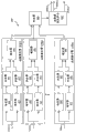
Fig. 1 is in a conceptive one exemplary embodiment having described the conventional receiver 100 that can use such as code division multiple access (CDMA) receiver in cellular telecommunication system.Receiver 100 comprises tracker 110, Rake receiver 120, Rake controller 130, searcher 140 and decoder 150.Those of ordinary skills should understand, though in Fig. 1, tracker 110, Rake receiver 120, Rake controller 130, searcher 140 and decoder 150 have been described as independently parts of function, this and what do not mean that these parts use is hardware engine independently.For example, in certain embodiments, because de-spreading operation has similitude, so tracker 110, searcher 140 and Rake receiver 120 can timesharing be shared one or more processing engine.
One or more composite baseband aerial signals 160 (1-n) can be offered tracker 110, Rake receiver 120 and searcher 140 here.In operation, the new images that searcher 140 just may occur and composite baseband aerial signal 160 (1-n) is searched for continuously, it also offers Search Results Rake controller 130 in addition, and each image that controller then can record searcher 140 is distributed to each branch road of Rake receiver 120.In addition, tracker 110 can also be followed the trail of the one or more delays that are associated with one or more branch roads of Rake receiver 120.Wherein for instance, Rake receiver 120 can comprise m branch road, and tracker 110 then can estimate the image propagates of distributing to each branch road to postpone.
Fig. 2 is in a conceptive one exemplary embodiment having described conventional tracker 110. and tracker 110 comprises a plurality of tracker engines 200 (1-m), though these tracker engines are used to the independent propagation delay that those are associated with each image in m the image of the m that distributes to Rake receiver 120 branch road of following the trail of. each tracker engine 200 (1-m) all is associated with a branch road in m the branch road, but the present invention is not limited to this embodiment that includes only the tracker 110 of m tracker engine 200 (1-m). in alternative embodiment, also can use less relatively tracker engine 200 (1-m). for example, also can use single tracker engine 200 (1-m) here and follow the trail of the image propagates that is associated with each branch road in the mode that the time shares and postpone.
Each tracker engine 200 (1-m) comprises multiplexer 210, correlator 215 and 220, adder 225 and 230, subtracter 240 and tracker judging part 250.Multiplexer 210 can receive the control signal from Rake controller 130, and can use this control signal to select a signal in the composite baseband aerial signal 160 (1-n).Correlator 215,220 can shift to an earlier date (corresponding to correlator 215) and lag behind (corresponding to correlator 220) described estimation image propagates postpones a very little incremental time and separates extended code with one and calibrate a selected composite baseband aerial signal 160 (1-n), thereby it is correlated with.Then, related output signal e and the l summation to coming autocorrelator 215,220 respectively in adder 225,230 is so that determine to offer the energy ‖ e ‖ of subtracter 240
2With ‖ l ‖
2
Subtracter 240 determines to come the related output signal energy difference of autocorrelator 215,220.Will produce synthetic energy difference ‖ e ‖ for each branch road here
2-‖ l ‖
2And it is fed to tracker judging part 250, and wherein these parts can use this energy difference to finely tune the propagation delay of estimation.For instance, if energy difference is very little, then tracker judging part 250 can determine the propagation delay of estimating roughly be in the branch road estimated postpone before (corresponding to correlator 215) and the centre of the very little incremental time of (corresponding to correlator 220) afterwards, and the actual propagation that the delay of being estimated is approximately equal to branch road postpones.Yet if energy difference is relatively large, tracker judging part 250 can use energy difference amplitude and/or energy difference sign to revise the propagation delay of estimation so.
Fig. 3 is in the conceptive one exemplary embodiment of describing routine search device 140.Composite baseband aerial signal 160 (1-n) is independently to offer correlator 300 (1-n), and it is the independently definite coherent signal of each antenna that these correlators can use each in postponing of a plurality of hypothesis to postpone to come.Adder 310 (1-n) postpones to determine the energy of each coherent signal for each hypothesis and for decision logic 320 provides this energy, described logic then determines whether one or more images that one or more hypothesis postpone are offered the one or more branch roads in the Rake receiver 120 by cooperating with Rake controller 130.In addition, decision logic 320 can also be cooperated with Rake controller 130, so that determine whether use the new branch road that is in selected delay to replace existing branch road.In addition, searcher 140 can also repeat this processing for a plurality of selected delays.
Fig. 4 is in the conceptive one exemplary embodiment of having described conventional Rake receiver 120, and this receiver comprises one or more Rake branch roads 410 (1-m).According to the control signal that Rake controller 130 provides, here can use multiplexer 400 in each Rake branch road 410 (1-m) select one with the corresponding composite baseband aerial signal 160 of the image that is assigned to Rake branch road 410 (1-m) (1-n).Selected composite baseband aerial signal 160 can be provided for correlator 420, and this correlator can form related output signal and this related output signal is offered channel-estimator 425.Channel-estimator 425 can be defined as the channel estimated value of the image that Rake branch road 410 (1-m) distributed, and a offers channel arrester 430 with this channel estimated value, and described arrester then can use the channel estimated value to come the channel of compensating image data part induct amplitude and/or phase distortion.Then, channel arrester 430 can provide a data-signal through overcompensation for adder 435, adder then can be to suing for peace from the data-signal through overcompensation of Rake branch road 410 (1-m), so that form and corresponding data splitting output of n the compound baseband signal that antenna received 160 (1-n) or soft symbol.In one embodiment, the correlator 420 of each Rake branch road 410 (1-m), channel-estimator 425 and channel arrester 430 can be shared by timesharing by one or more groups hardware.
Except main ray, the signal that mobile unit is launched also may produce the one or more time echoes that have one or more propagation time delaies that are associated. when comprising more than one reception antenna in the base station, each echo or ray are received by each antenna, produced thus and the corresponding a plurality of images of a plurality of reception antennas. for instance, comprise k ray if transmit and be to receive by base station with n antenna, the base station will receive and amount to k*n corresponding to the image that transmits so. as mentioned above, each receives conventional receiver 100 independent process image and each reception image is distributed to independently Rake branch road. so, each branch road all is to carry out independent the tracking with independent tracker, and wherein said tracker will independently be estimated the propagation delay of each image.
Summary of the invention
One or more effects that the present invention is intended to address the above problem.
In one embodiment of the invention, provide a kind of method that is used for intelligent antenna receiver architecture.This method comprises: receive a plurality of first signals corresponding to a plurality of antennas, determine the value that at least one represents the nonrandom part of a plurality of first signals, and represent that according at least one the value of the nonrandom part of a plurality of first signals revises a plurality of first signals, so that form a plurality of secondary signals.
In another embodiment of the present invention, provide a kind of equipment that is used for intelligent antenna receiver architecture.This equipment comprises: signal converter, be used for receiving and corresponding a plurality of first signals of a plurality of antennas, determine the value that at least one represents the nonrandom part of a plurality of first signals, and represent that according at least one the value of the nonrandom part of a plurality of first signals revises a plurality of first signals, thereby form a plurality of secondary signals.
Description of drawings
The present invention can understand by obtaining with reference to description taken together with the accompanying drawings hereinafter, wherein identical reference number sign be same parts, and wherein:
Fig. 1 is in a conceptive one exemplary embodiment having described the prior art receiver;
Fig. 2 is in a conceptive one exemplary embodiment having described the prior art tracker that can use in receiver shown in Figure 1;
Fig. 3 is in a conceptive one exemplary embodiment having described the prior art searcher that can use in receiver shown in Figure 1;
Fig. 4 is in the conceptive one exemplary embodiment of having described the prior art Rake receiver that can use in receiver shown in Figure 1;
Fig. 5 is in the conceptive one exemplary embodiment of having described according to the receiver of one embodiment of the invention;
Fig. 6 is in the conceptive one exemplary embodiment of having described according to the one embodiment of the invention and the searcher that can use in receiver shown in Figure 5;
Fig. 7 is in the conceptive one exemplary embodiment of having described according to the one embodiment of the invention and the tracker that can use in receiver shown in Figure 5;
Fig. 8 conceptive described according to one embodiment of the invention and can in tracker shown in Figure 7, use group tracker one exemplary embodiment.
Though the present invention can accept different modifications and replacement form, and described modification and the specific embodiment of replacing form show as an example and in the accompanying drawings also and are here described in detail.Yet should be appreciated that, here, about the description of specific embodiment and do not mean that and will limit the invention to disclosed particular form, in contrast, it is intended that and covers defined essence of the present invention and the scope of falling into of accessory claim with interior all modifications, equivalent and substitute mode.
Embodiment
To be described one exemplary embodiment of the present invention hereinafter.All features of actual execution mode for clarity sake, are not described in the specification.But should be appreciated that, undoubtedly, in the process of this type of practical embodiments of exploitation, will make a lot of judgements specific to execution mode, so that realize developer's specific purposes, for example adapt with the constraints that relates to system and enterprise, these constraintss can change along with the difference of execution mode.Be also to be understood that in addition this type of development may be very complicated and very consuming time, but still can be carried out by having benefited from those of ordinary skills of the present disclosure.
Fig. 5 is in a conceptive one exemplary embodiment having described the receiver 500 that comprises signal converter 505.Will in the cellular telecommunication system environment of employing code division multiple access (CDMA) agreement, one exemplary embodiment shown in Figure 5 be described hereinafter.Yet those of ordinary skills should understand, and the present invention is not limited to use the cellular telecommunication system of CDMA agreement.In alternative embodiment, the present invention can comprise in use in the wireless communication system of any expection of any expection agreement of agreements such as UMTS, IS-95, WLAN (wireless local area network) and implementing.
Signal converter 505 receives a plurality of composite baseband aerial signals 510 (1-n) that can offer autocorrelator 515.Described autocorrelator 515 is determined the value of the nonrandom part of at least one expression composite baseband aerial signal 510 (1-n).In one embodiment, composite baseband aerial signal 510 (1-n) is as the compound column vector X=(x (1) that offers autocorrelator 515, x (2), ..., x (n)) represents, wherein said autocorrelator can be carried out auto-correlation processing to compound column vector X, so that produce an autocorrelation matrix R
XxThe signal of expression autocorrelation matrix can be provided to inverted converter 520 here, described inverted converter then can use the signal that provides to produce a reverse autocorrelation matrix R
Xx -1Inverted converter 520 can provide the signal of the reverse autocorrelation matrix of expression to resolving cell 525, and this resolving cell can use the signal that provides to decompose reverse autocorrelation matrix and produce split-matrix P.In one embodiment, split-matrix can use equation
 Calculate.
In illustrative embodiments, a plurality of composite baseband aerial signals 510 (1-n) are offered linear quantizer unit 530, this unit further receives the signal of expression from the split-matrix of resolving cell 525.Linear quantizer unit 530 can use a plurality of composite baseband aerial signals 510 (1-n) and be used to represent that the signal of split-matrix comes a plurality of composite baseband aerial signals 510 of conversion (1-n), thereby forms corresponding a plurality of aerial signal 540 (1-n) through revising.In one embodiment, composite baseband aerial signal 510 (1-n) can be revised by linear transformation being applied to compound column vector X in linear quantizer unit 530, thus form the second compound column vector Y=(y (1), y (2) ..., y (n)).For example, linear quantizer unit 530 can the given linear transformation of applicable equations Y=PX.Then, the second compound column vector Y can be used to form a plurality of aerial signals 540 (1-n) through revising.
The present invention forms corresponding a plurality ofly through the aerial signal 540 (1-n) revised by revising composite baseband aerial signal 510 (1-n), can reduce one or more effects of the unexpected part of composite baseband aerial signal 510 (1-n) thus.For instance, those of ordinary skills should understand, if use reverse autocorrelation matrix in the Linear Transformation, then can reduce the mean square error between received signal and the known array (for example pilot frequency sequence).For another example, if in composite baseband aerial signal 510 (1-n), have one or more strong subscriber signals, high reject signal or the like, autocorrelation matrix might comprise one or more very big eigenvalues so, and these eigenvalues are represented the nonrandom part of composite baseband aerial signal 510 (1-n).So, by using reverse autocorrelation matrix to come conversion composite baseband aerial signal 510 (1-n) thus form corresponding a plurality of during through the aerial signal 540 (1-n) revised, can with the proportional situation of reciprocal transformation of corresponding one or more big eigenvalues under, reduce the amplitude of strong subscriber signal and/or high reject signal.
Can offer tracker 545, Rake receiver 550 and searcher 555 through the aerial signal of revising 540 (1-n) with a plurality of here.In one embodiment, searcher 555 new images that just may occur and searching for continuously through the aerial signals of revising 540 (1-n) to a plurality of.Yet those of ordinary skills should understand, and the present invention is not limited to this new images that just may occur and to a plurality of searchers of searching for continuously through the aerial signals of revising 540 (1-n) 555.In alternative embodiment, the new images that searcher 555 both can periodically just may occur and searching for through the aerial signals of revising 540 (1-n) to a plurality of, also can selected at interval on, search in response to control signal or in other any desired times.
Searcher 555 offers Rake controller 560 with Search Results, and each image that this controller then detects searcher 555 is distributed to the respective branch of Rake receiver 550.In addition, tracker 545 can also independent be followed the trail of the delay of the branch road that the one or more Rake of being associated with receivers 550 are distributed, and decision signal 551 (1-m) can be offered Rake receiver 550.In one embodiment, decision signal 551 (1-m) comprises one or more estimation propagation delays.Wherein for instance, Rake receiver 550 can comprise m branch road, and tracker 545 can be estimated the propagation delay of the image of distributing to each branch road.In addition, Rake receiver 550 can also provide signal, for example a soft symbol to decoder 570.
Yet, in an alternative embodiment, the image that the ray that searcher 555 receives with regard to a plurality of and a plurality of antennas is associated and searching for through the aerial signals of revising 540 (1-n) to a plurality of.Searcher 555 offers Rake controller 560 with Search Results, and each image in a plurality of images that this controller can detect searcher 555 is distributed to corresponding a plurality of branch roads of Rake receiver 550.Hereinafter, a plurality of branch roads are called the branch road group.And for instance, the base station (not shown) can comprise n antenna, and Rake receiver 550 can comprise m branch road, and therefore, Rake receiver 550 can be handled m/n branch road group.Tracker 545 can also be followed the trail of a propagation delay related with the branch road faciation.Though may not equate fully with the delay that each branch road among the branch road group is associated, for instance, the length in one or more path from mobile unit to a plurality of antennas may not equate, but those of ordinary skills should understand, and those can be considered as being small enough to the degree that is enough to ignore with difference between the delay that each branch road is associated in environment of the present invention.
Fig. 6 is in the conceptive one exemplary embodiment of having described the searcher 555 that can be used for detecting a plurality of images that the ray that receives with a plurality of antennas is associated.In operation, wherein offer correlator 600 (1-n) with a plurality of through the aerial signals of revising 540 (1-n), this correlator can be determined to postpone the coherent signal that is associated with one or more hypothesis of each antenna.Adder 610 (1-n) receives coherent signal and is that each selected hypothesis postpones to determine each coherent signal energy.Then, adder 610 (1-n) can offer this energy adder 615, and described adder 615 uses selected hypothesis to postpone will be corresponding to the energy summation of a plurality of antennas.Accordingly, adder 615 will merge for carrying out diversity corresponding to the coherent signal of each antenna.In addition, adder 615 can also offer decision logic 620 with the summation energy that postpones about one or more hypothesis, and described decision logic then determines whether should be with the branch road that is among the branch road group that the selected a plurality of images that postpone offer Rake receiver 550.In addition, decision logic 620 can also determine whether and replace existing branch road group with being in the selected new branch road group who postpones, and searcher 555 can be handled for a plurality of selected delays repeat this, so that determine the optimal delay estimated value related with the branch road faciation.
Fig. 7 is in a conceptive one exemplary embodiment having described tracker 545, and described tracker can be used for a plurality of branch roads of trace branches group.Offer a plurality of groups of trackers 700 (1-m/n) with a plurality of through the aerial signals of revising 540 (1-n) here, wherein can use these trackers to come a plurality of branch roads among the trace branches group.As mentioned above, the base station (not shown) can comprise n antenna, and Rake receiver 550 can comprise m branch road, and so tracker 545 might comprise m/n group's tracker 700 (1-m/n) at least, so that handle m/n branch road group.
Each group tracker 700 (1-m/n) all provides the part in a plurality of decision signals 710 (l-m). for example, group's tracker 700 (1) provides decision signal 700 (1-n). in illustrative embodiments, signal 700 (1-n) can transmit the estimation propagation delay that is associated with n branch road among the branch road group. by n signal 700 (1-n) is provided, can revise the interface between group tracker 700 (1-m/n) and the Rake receiver 550. but the present invention is not limited thereto. in alternative embodiment, group's tracker 700 (l-m/n) can provide more or less relatively decision signal. for example, group's tracker 700 (1) can provide single decision signal 700 (1). and as shown in Figure 7, each group tracker 700 (1-m/n) can independent trace branches group.
Fig. 8 is in a conceptive one exemplary embodiment describing group's tracker 800.Group's tracker 800 comprises a plurality of tracker engines 810 (1-n), and they can be used to each image calculation in n the image among the branch road group to measure, and wherein said measuring with branch road group's same propagation delay is associated.Though each tracker engine 810 (1-n) is all related with one of them branch road faciation, the present invention is not limited to only to comprise the embodiment of group's tracker 800 of n tracker engine 810 (1-n).In alternative embodiment, more or less relatively tracker engine 810 (1-n) also is operable.For example, single tracker engine 810 (1-n) can be used to follow the trail of the propagation delay that is associated with each branch road group in the mode that timesharing is shared.
Each tracker engine 810 (1-n) comprises correlator 820,825, adder 830,835 and subtracter 840.In illustrative embodiments, offer correlator 820,825 in the corresponding tracker engine 810 (1-n) through each signal in the aerial signal of revising 540 (1-n) with a plurality of.Correlator 820,825 can shift to an earlier date (corresponding to correlator 820) or lag behind (corresponding to correlator 825) estimation very little incremental time of picture delay and with separate extended code calibrate a plurality of through an appropriate signal in the aerial signal of revising 540 (1-n), thereby come its execution associative operation.For example, correlator 820,825 can use PN skew, Walsh sign indicating number or the like to proofread and correct through each signal in the aerial signal of revising 540 (1-n) a plurality of.Then, will be from the related output signal e (k) of the correlator 820,825 of tracker engine 810 (k) and l (k) respectively in adder 830, summation in 835 is so that definite respectively " in early days " and " later stage " energy ‖ e (k) ‖ that is associated with amended aerial signal 540 (1-n)
2With ‖ l (k) ‖
2, these energy then offer the subtracter 840 of tracker engine 840 (k).

Energy difference is measured the estimation propagation delay that also can be used to finely tune the branch road group.For instance, if energy difference is very little, so tracker identifying unit 850 can determine to estimate propagation delay approximately be in the estimation branch road postpone before (corresponding to correlator 820) and the middle of the small incremental time of (corresponding to correlator 825) afterwards, and the practical application that estimated delays is approximately equal to the branch road group postpones.Yet if energy difference is relatively large, tracker identifying unit 850 sign that can use amplitude that energy difference measures and/or energy difference to measure is revised branch road group's estimation propagation delay so.
Above-mentioned high efficiency smart aerial receiver framework has separated the smart antenna function to a great extent from conventional receiver components, compare with previous smart antenna execution mode, described framework has greatly been simplified execution mode. according to the disclosure, those skilled in the art can understand, above-mentioned framework also can produce those mean square error between received signal and the institute's attention signal is reduced to minimum soft symbol. so, the framework that is proposed can also provide improved diversity to merge, aperture gain, interference eliminated and other benefits. in addition, can also provide these benefits to carry out demodulation and tracking/search equipment here, yet but go to revise Rake receiver or tracking/search equipment., if implement the branch road group in the above described manner, then can further improve the efficient of aforementioned intelligent antenna frame.
High efficiency smart receiver architecture described herein has also reduced the change for the conventional Rake framework of not implementing smart antenna, has still realized simultaneously can be used for the performance gain of the smart antenna Processing Algorithm of reverse link.For example, in a previous embodiment of the present invention, wherein can add four functional blocks in the Rake of routine receiver the place ahead,, and use the P matrix to come original antenna data is carried out linear transformation so that generate a P matrix.Then, as mentioned above, under the situation of a small amount of change Rake controller part, tracker parts, searcher parts, output signal can be fed to conventional Rake receiver.
Above-mentioned specific embodiment is just in order to demonstrate, and according to the instruction here, those skilled in the art can know understanding, and the present invention can be with different equivalents correct and enforcement.In addition, except the described content of following claim, here shown construction or design details is not limited.Therefore, clearly, above disclosed specific embodiment can change or revise, and all these variations all are regarded as being in scope of the present invention and the essence.Correspondingly, the protection range of seeking here is elaborated in following claim.
Claims (2)
1. method that is used for intelligent antenna receiver architecture comprises:
Reception is corresponding to a plurality of first signals of a plurality of antennas, and wherein a plurality of first signals comprise a plurality of first images that are associated with first ray corresponding to first transmitter;
Described a plurality of first signals of auto-correlation produce an autocorrelation matrix, represent the value of the nonrandom part of a plurality of first signals to determine at least one;
Use the inverse value of the value of at least one nonrandom part of representing a plurality of first signals to come a plurality of first signals of linear transformations, so that form a plurality of secondary signals; And
Use a plurality of secondary signals to detect a plurality of first images,
Wherein a plurality of first signals of linear transformations comprise:
The reciprocal transformation autocorrelation matrix;
The autocorrelation matrix that decomposes reciprocal transformation; And
According to the autocorrelation matrix that passes through decomposition and reciprocal transformation and to a plurality of first signal application linear transformations,
And wherein using a plurality of secondary signals to detect a plurality of first images comprises:
A plurality of secondary signals are sued for peace; And
With regard to a plurality of first images and to searching for through a plurality of secondary signals of summation;
A plurality of first images are distributed to a plurality of first branch roads;
Be associated with under the situation that the propagation delay estimated value of a plurality of first branch roads equates in hypothesis, handle being associated with as one or more signals of a plurality of first branch roads of the first branch road group,
And described processing comprises:
The one or more signals that are associated with a plurality of first branch roads are sued for peace; And
Follow the trail of the one or more signals that are associated with a plurality of first branch roads through summation.
2. equipment that is used for intelligent antenna receiver architecture comprises:
Signal converter, it is configured to:
Reception is corresponding to a plurality of first signals of a plurality of antennas;
Determine the value that at least one represents the nonrandom part of a plurality of first signals; And
Represent that according at least one the value of the nonrandom part of a plurality of first signals revises a plurality of first signals, thereby form a plurality of secondary signals,
And wherein signal converter comprises:
Be configured to produce the autocorrelator of autocorrelation matrix according to a plurality of first signals;
Be configured to autocorrelation matrix is carried out the inverted converter of reciprocal transformation;
Be configured to the resolving cell that the autocorrelation matrix to reciprocal transformation decomposes; And
Be configured to linear transformation is applied to the linear transform unit of a plurality of first signals according to the autocorrelation matrix that passes through decomposition and reciprocal transformation; And
Described equipment also comprises tracker, receiver, in receiver controller and the searcher at least one, wherein signal converter is configured to a plurality of secondary signals are offered tracker, receiver, and in the searcher at least one, and wherein searcher be configured to a plurality of secondary signals sue for peace and with regard to a plurality of first images and to through the summation a plurality of secondary signals search for, and wherein receiver controller is configured to a plurality of first images are distributed to a plurality of first branch roads, and wherein tracker is configured to related one or more signals with a plurality of first branch roads are sued for peace, and to being associated with a plurality of first branch roads and following the trail of through one or more signals of summation.
Applications Claiming Priority (2)
| Application Number | Priority Date | Filing Date | Title |
|---|---|---|---|
| US10/825,851 | 2004-04-16 | ||
| US10/825,851 US20050232340A1 (en) | 2004-04-16 | 2004-04-16 | Intelligent antenna receiver architecture |
Publications (2)
| Publication Number | Publication Date |
|---|---|
| CN1684392A CN1684392A (en) | 2005-10-19 |
| CN1684392B true CN1684392B (en) | 2010-05-12 |
Family
ID=34940621
Family Applications (1)
| Application Number | Title | Priority Date | Filing Date |
|---|---|---|---|
| CN2005100659147A Expired - Fee Related CN1684392B (en) | 2004-04-16 | 2005-04-15 | Method and equipment for an intelligent antenna receiver architecture |
Country Status (6)
| Country | Link |
|---|---|
| US (1) | US20050232340A1 (en) |
| EP (1) | EP1587220B1 (en) |
| JP (1) | JP4772364B2 (en) |
| KR (1) | KR101129234B1 (en) |
| CN (1) | CN1684392B (en) |
| DE (1) | DE602005015784D1 (en) |
Families Citing this family (5)
| Publication number | Priority date | Publication date | Assignee | Title |
|---|---|---|---|---|
| US20060046775A1 (en) * | 2004-08-31 | 2006-03-02 | Geiger Edward W | Intelligent antenna and method for configuring the same |
| US20070280146A1 (en) * | 2006-05-30 | 2007-12-06 | Shirish Nagaraj | System and method for estimating uplink signal power |
| US8126031B2 (en) * | 2007-08-07 | 2012-02-28 | Qualcomm Incorporated | Time-tracking management of demodulation elements in a receive diversity enabled rake receiver |
| US9031118B2 (en) * | 2012-05-21 | 2015-05-12 | Avidyne Corporation | Virtual floating correlators for GPS sensor |
| JP6156308B2 (en) * | 2014-09-24 | 2017-07-05 | 住友電装株式会社 | Electrical junction box |
Citations (2)
| Publication number | Priority date | Publication date | Assignee | Title |
|---|---|---|---|---|
| US20030035468A1 (en) * | 2001-05-17 | 2003-02-20 | Corbaton Ivan Jesus Fernandez | System and method for adjusting combiner weights using an adaptive algorithm in wireless communications system |
| CN1416622A (en) * | 2000-01-26 | 2003-05-07 | 高通股份有限公司 | Multipath doppler-adjusted frequency tracking loop |
Family Cites Families (5)
| Publication number | Priority date | Publication date | Assignee | Title |
|---|---|---|---|---|
| FR2715488B1 (en) * | 1994-01-21 | 1996-03-22 | Thomson Csf | Method and device enabling a modem to synchronize with a digital data transmitter over the air in the presence of jammers. |
| WO1999020061A2 (en) * | 1997-10-14 | 1999-04-22 | Siemens Aktiengesellschaft | Method and receiving device for estimating channels in communications systems |
| US6714527B2 (en) * | 1999-09-21 | 2004-03-30 | Interdigital Techology Corporation | Multiuser detector for variable spreading factors |
| US7079480B2 (en) * | 2000-10-28 | 2006-07-18 | Agee Brian G | Enhancing security and efficiency of wireless communications through structural embedding |
| JP3763793B2 (en) * | 2002-03-12 | 2006-04-05 | 株式会社東芝 | Receiver and transmitter / receiver |
-
2004
- 2004-04-16 US US10/825,851 patent/US20050232340A1/en not_active Abandoned
-
2005
- 2005-03-23 DE DE602005015784T patent/DE602005015784D1/en active Active
- 2005-03-23 EP EP05251767A patent/EP1587220B1/en not_active Expired - Fee Related
- 2005-04-08 KR KR1020050029440A patent/KR101129234B1/en not_active IP Right Cessation
- 2005-04-15 CN CN2005100659147A patent/CN1684392B/en not_active Expired - Fee Related
- 2005-04-15 JP JP2005117630A patent/JP4772364B2/en not_active Expired - Fee Related
Patent Citations (2)
| Publication number | Priority date | Publication date | Assignee | Title |
|---|---|---|---|---|
| CN1416622A (en) * | 2000-01-26 | 2003-05-07 | 高通股份有限公司 | Multipath doppler-adjusted frequency tracking loop |
| US20030035468A1 (en) * | 2001-05-17 | 2003-02-20 | Corbaton Ivan Jesus Fernandez | System and method for adjusting combiner weights using an adaptive algorithm in wireless communications system |
Also Published As
| Publication number | Publication date |
|---|---|
| CN1684392A (en) | 2005-10-19 |
| DE602005015784D1 (en) | 2009-09-17 |
| EP1587220A3 (en) | 2008-02-27 |
| EP1587220A2 (en) | 2005-10-19 |
| JP2005312038A (en) | 2005-11-04 |
| US20050232340A1 (en) | 2005-10-20 |
| KR101129234B1 (en) | 2012-03-27 |
| KR20060046649A (en) | 2006-05-17 |
| EP1587220B1 (en) | 2009-08-05 |
| JP4772364B2 (en) | 2011-09-14 |
Similar Documents
| Publication | Publication Date | Title |
|---|---|---|
| US6067324A (en) | Method and system for transmitting and demodulating a communications signal using an adaptive antenna array in a wireless communication system | |
| CN1957540B (en) | Impairment correlation estimator in a spread spectrum system and estimation method | |
| CN1305230C (en) | Practical space-time radio method for cdma communication capacity enhancement | |
| US6108565A (en) | Practical space-time radio method for CDMA communication capacity enhancement | |
| US6347234B1 (en) | Practical space-time radio method for CDMA communication capacity enhancement | |
| US6788734B2 (en) | Rake receiver for spread spectrum signal demodulation | |
| US7333774B2 (en) | Method of optimizing wireless communication links using stored channel characteristics of different locations | |
| KR100913883B1 (en) | Apparatus and method for calibrating and compensating output signal distortion of smart antenna | |
| US6462709B1 (en) | Signal processing method and apparatus for computing an optimal weight vector of an adaptive antenna array system | |
| JP3156768B2 (en) | Cellular base station and position locating device mounted on it | |
| JP4295112B2 (en) | Construction of interference matrix for coded signal processing engine | |
| CN100544231C (en) | Smart antenna implementation method and smart antenna based on software radio are realized system | |
| KR20030015616A (en) | Apparatus for Forward Beamforming using Feedback of Multipath Information and Method Thereof | |
| CN1684392B (en) | Method and equipment for an intelligent antenna receiver architecture | |
| US20040077322A1 (en) | Method for receiving multipath signals in a radio communications system with a code division multiple access and device for carrying out said method | |
| KR100770498B1 (en) | A smart antenna and a method and a device for forming beam of the smart antenna | |
| WO1998008319A9 (en) | Rake receiver for spread spectrum signal demodulation | |
| WO1998008319A1 (en) | Rake receiver for spread spectrum signal demodulation | |
| CN101133659B (en) | Intelligent antenna implementing method based on software radio and implement system thereof | |
| Lili et al. | A blind calibration method for smart antenna system | |
| Lacatus et al. | Implementation approaches of adaptive algorithms for crosscorrelation effect compensation in weak signal conditions | |
| CN1998154A (en) | Deconvolution searcher for wireless communication system |
Legal Events
| Date | Code | Title | Description |
|---|---|---|---|
| C06 | Publication | ||
| PB01 | Publication | ||
| C10 | Entry into substantive examination | ||
| SE01 | Entry into force of request for substantive examination | ||
| C14 | Grant of patent or utility model | ||
| GR01 | Patent grant | ||
| CF01 | Termination of patent right due to non-payment of annual fee |
Granted publication date: 20100512 Termination date: 20180415 |
|
| CF01 | Termination of patent right due to non-payment of annual fee |