CN1663807A - Tape supply cartridge - Google Patents
Tape supply cartridge Download PDFInfo
- Publication number
- CN1663807A CN1663807A CN200510055849XA CN200510055849A CN1663807A CN 1663807 A CN1663807 A CN 1663807A CN 200510055849X A CN200510055849X A CN 200510055849XA CN 200510055849 A CN200510055849 A CN 200510055849A CN 1663807 A CN1663807 A CN 1663807A
- Authority
- CN
- China
- Prior art keywords
- belt
- paper tape
- box
- feed cassette
- paper
- Prior art date
- Legal status (The legal status is an assumption and is not a legal conclusion. Google has not performed a legal analysis and makes no representation as to the accuracy of the status listed.)
- Granted
Links
Images


Classifications
-
- B—PERFORMING OPERATIONS; TRANSPORTING
- B41—PRINTING; LINING MACHINES; TYPEWRITERS; STAMPS
- B41J—TYPEWRITERS; SELECTIVE PRINTING MECHANISMS, i.e. MECHANISMS PRINTING OTHERWISE THAN FROM A FORME; CORRECTION OF TYPOGRAPHICAL ERRORS
- B41J15/00—Devices or arrangements of selective printing mechanisms, e.g. ink-jet printers or thermal printers, specially adapted for supporting or handling copy material in continuous form, e.g. webs
- B41J15/04—Supporting, feeding, or guiding devices; Mountings for web rolls or spindles
- B41J15/044—Cassettes or cartridges containing continuous copy material, tape, for setting into printing devices
-
- B—PERFORMING OPERATIONS; TRANSPORTING
- B41—PRINTING; LINING MACHINES; TYPEWRITERS; STAMPS
- B41J—TYPEWRITERS; SELECTIVE PRINTING MECHANISMS, i.e. MECHANISMS PRINTING OTHERWISE THAN FROM A FORME; CORRECTION OF TYPOGRAPHICAL ERRORS
- B41J15/00—Devices or arrangements of selective printing mechanisms, e.g. ink-jet printers or thermal printers, specially adapted for supporting or handling copy material in continuous form, e.g. webs
- B41J15/04—Supporting, feeding, or guiding devices; Mountings for web rolls or spindles
-
- B—PERFORMING OPERATIONS; TRANSPORTING
- B41—PRINTING; LINING MACHINES; TYPEWRITERS; STAMPS
- B41J—TYPEWRITERS; SELECTIVE PRINTING MECHANISMS, i.e. MECHANISMS PRINTING OTHERWISE THAN FROM A FORME; CORRECTION OF TYPOGRAPHICAL ERRORS
- B41J17/00—Mechanisms for manipulating page-width impression-transfer material, e.g. carbon paper
- B41J17/02—Feeding mechanisms
-
- B—PERFORMING OPERATIONS; TRANSPORTING
- B41—PRINTING; LINING MACHINES; TYPEWRITERS; STAMPS
- B41J—TYPEWRITERS; SELECTIVE PRINTING MECHANISMS, i.e. MECHANISMS PRINTING OTHERWISE THAN FROM A FORME; CORRECTION OF TYPOGRAPHICAL ERRORS
- B41J3/00—Typewriters or selective printing or marking mechanisms characterised by the purpose for which they are constructed
- B41J3/407—Typewriters or selective printing or marking mechanisms characterised by the purpose for which they are constructed for marking on special material
- B41J3/4075—Tape printers; Label printers
-
- B—PERFORMING OPERATIONS; TRANSPORTING
- B41—PRINTING; LINING MACHINES; TYPEWRITERS; STAMPS
- B41J—TYPEWRITERS; SELECTIVE PRINTING MECHANISMS, i.e. MECHANISMS PRINTING OTHERWISE THAN FROM A FORME; CORRECTION OF TYPOGRAPHICAL ERRORS
- B41J31/00—Ink ribbons; Renovating or testing ink ribbons
- B41J31/12—Ink ribbons having arrangements to prevent undesired contact between the impression-transfer material and machine parts or other articles
-
- B—PERFORMING OPERATIONS; TRANSPORTING
- B41—PRINTING; LINING MACHINES; TYPEWRITERS; STAMPS
- B41J—TYPEWRITERS; SELECTIVE PRINTING MECHANISMS, i.e. MECHANISMS PRINTING OTHERWISE THAN FROM A FORME; CORRECTION OF TYPOGRAPHICAL ERRORS
- B41J35/00—Other apparatus or arrangements associated with, or incorporated in, ink-ribbon mechanisms
- B41J35/04—Ink-ribbon guides
Abstract
A tape supply cartridge (10) for use in a printer of the type having a fixed print head (7), a movable platen roller (8) and a pair of tape advancement rollers (20, 9), one in the cartridge and one in the printer.
Description
Technical field
The present invention relates generally to a kind of paper strip supply box, particularly, relates to a kind of paper strip supply box that is used for price labeling, and this price labeling is used for mark is printed on this paper tape, pastes on the desired substance selectively so that be used for.Further specifically, the present invention relates to be often used as paper strip supply box not stratified, heat-transferring printing paper band feed cassette type.
Background technology
The paper strip supply box and relevant patent that have now had the prior art that is used to connect label or strip printer etc. in a large number.These paper strip supply boxes provide the print paper of coiling to printhead, are used for franking on the paper tape that will be pasted selectively subsequently on the desired substance.United States Patent(USP) Nos. 5,188,469; 5,350,243; 5,653,542; 5,813,773; 4,927,278; 4,983,058 and 5,419,648 grades have exemplified and disclose some paper strip supply boxes in these paper strip supply boxes.These paper strip supply boxes are designed in price labeling or the printer, these price labelinies or printer have and are used for this box is contained in the box container cavity of an operable position, a thermal printer head and an air roll that is associated, this association pressure roller by selectively towards or deviate from printhead and move, and paper tape is placed between related pressure roller and the printhead, its objective is for photographic fixing image or transferred image on this paper tape.Such price labeling or printer also comprise and are used to advance paper tape to pass printhead and advance various other the devices of spool element by equipment.
Though the paper strip supply box of prior art for their special applications, can be worked satisfactorily, still constantly need such paper strip supply box be improved.Constantly the principal character of need for improved comprises herein: the relative Transfer ribbon of paper strip supply box is held the ability of the paper tape of different size and width, and paper strip supply box guiding paper tape passes this feed cassette and the ability of the paper tape resistance that guarantees simultaneously to reach suitable and the ability of paper strip supply box minimizes paper tape at cutting position obstruction etc.Therefore, need a kind of improved paper tape that is used for the paper strip supply box of above-mentioned bound printer and is used for this paper strip supply box.
Summary of the invention
An object of the present invention is to provide a kind of improved paper strip supply box that is used for price labeling or printer.
Another object of the present invention provides a kind of improved paper tape guiding device that is used for this feed cassette.
Another object of the present invention provides a kind of improved paper strip supply and guide in conjunction with the paper tape parameter, passes the optimization motion of feed cassette to guarantee paper tape, prevents the idle running of paper strip supply spool simultaneously.
Another object of the present invention is that the paper tape outlet end at feed cassette provides a kind of improved device, so that restriction or eliminate the obstructing problem that causes owing to the interaction between print paper and the paper tape cutter sweep.
Another object of the present invention provides a kind of improved paper strip supply box not stratified, hot transfer type.
The belt that the present invention relates to a kind of printer is supplied with article box, and described belt is supplied with article box and comprised: belt is supplied with the spool of article; Image is sent to transfer belt spool on the belt; With the guiding device that guides belt aliment product and transfer belt by lead arm; Described lead arm comprises: described guiding device; Lateral wall; Madial wall; Described guiding device and lateral wall form the belt guiding channel that belt is supplied with article; Described guiding device and madial wall form independent transfer belt guiding channel; Described guiding device has at least one ledge, and described at least one ledge is all higher than described lateral wall and madial wall.
By with reference to the accompanying drawings, to the explanation of preferred embodiment and the appended claims, it is clearer that these and other objects of the present invention will become.
Description of drawings
Fig. 1 is the isometric view according to paper strip supply box of the present invention.
Fig. 2 is isogonism, the decomposition view of paper strip supply box of the present invention.
Fig. 3 is the inboard elevation at the bottom of the paper strip supply box of the present invention, and wherein this paper strip supply box has paper strip supply spool, colour band supply spool and colour band is recoiled spool, and various other element is removed.
Fig. 4 is the inboard elevation on paper strip supply box top.
Fig. 5 is the upright figure in the end of the paper strip supply box that assembles.
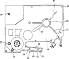
Fig. 6 is the inside stand figure at the bottom of the paper strip supply box similar to Fig. 3, has represented the path of paper tape and colour band.
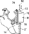
Fig. 7 is a partial view, has partly represented the paper tape outlet end of the paper strip supply box that combines with the paper tape cutter sweep.
Fig. 8 is the local preceding upright figure of the paper tape outlet end of paper strip supply box.
Fig. 9 has represented the view of the paper strip supply box similar to Fig. 6, and wherein this paper strip supply box combines second embodiment of paper tape cutter sweep.
Figure 10 is a phantom, has represented along the view of the hatching 10-10 among Fig. 3.
Figure 11 a is a phantom, has represented along the view of the hatching 11-11 among Figure 10.
Figure 11 b is a view similar to Figure 11 a, and just the top and bottom with paper strip supply box fits together.
Figure 12 is a phantom, has represented another embodiment similar to FIG. 10.
Figure 13 a is a phantom, has represented along the view of the hatching 13-13 among Figure 12.
Figure 13 b is a view similar to Figure 13 a, and just the top and bottom with paper strip supply box fits together.
Figure 14 is the partial sectional view of the part of paper strip supply box, has represented to be installed in the paper tape supply between the two halves paper strip supply box.
Figure 15 is a phantom, has represented along the view of Fig. 3 section line 15-15.
Figure 16 is a cutaway view, has represented the structure of paper tape.
The specific embodiment
The present invention relates to a kind of paper strip supply box, particularly, relate to a kind of not stratified paper strip supply box that is often used as.Such paper strip supply box is designed in price labeling or the printer, these price labelinies or printer comprise a paper strip supply box container cavity, a printhead 7 (Fig. 6), one can towards or deviate from printhead 7 and move to limit and print and the air roll 8 of non-print position, be used to advance paper tape and colour band to pass paper strip supply box and through the device of printing station with after printing, cut off the device of paper tape selectively.
In the explanation to the preferred embodiment of the present invention, at first referring to Fig. 1 and Fig. 2, wherein Fig. 1 has represented the feed cassette of the form of assembling fully, and Fig. 2 has represented the feed cassette of decomposed form.In general, feed cassette 10 comprises at the bottom of feed cassette top 11 and the feed cassette 12.During assembling, will push up 11 and the end 12 be fixed together and constitute feed cassette 10, this feed cassette 10 holds paper tape supply 13, colour band supply spool 23 and ribbon spool tape spool 17.Printhead cavity or grooved area 16 that this feed cassette also comprises paper tape outlet end 14, is arranged on the paper tape outlet groove 15 on this paper tape outlet end 14 and is used to hold printhead when this feed cassette is inserted in the printer.This printhead cavity is fixed at a lateral confinement by paper tape/color-band guide arm 38, and wherein this lead arm 38 is used for paper tape and color-band guide to printing station.Feed cassette top 11 and the zone 18 and 19 at the end 12 limit the zone of capacity ribbon supply spool 23 and ribbon spool tape spool 17 respectively.Paper tape advances roller 20 to be set at the paper tape outlet end of feed cassette.In a preferred embodiment, roller 20 is the driving feeding-in rolls with internal spline, muscle or other device that matches with the printer driver axle.
Referring to Fig. 2 and Fig. 3,12 inside is represented fully aware ofly at the bottom of the feed cassette.As shown in the figure, 12 comprise diapire 25 and sidewall 24 at the bottom of the feed cassette, and this sidewall 24 extends upward and center on the essential part extension of feed cassette basically by the right angle from diapire 25.Being processed into holistic with diapire 25 is paper strip supply hub 26 and several paper tape brace rods 28, and these paper tape brace rods 28 extend radially outwardly from hub 26.Hub 26 common cylindrical structures extend upward by the right angle basically from diapire 25, and it act as the hub 84 that rotatably supports paper strip supply spool 13.A pair of paper tape containment wall part 29,29 is set for paper strip supply spool 13 is included in the ringwise substantially structure.The paper tape guiding wall 30 of elongation extends to paper tape between a pair of wall part that separates 32,32 by groove 31 from the inside part of sidewall 24.This guiding wall 30 extends upward by the right angle basically from diapire 25, and guarantees and will also guide to paper tape by groove 31 from paper tape spool 13 exactly from the paper tape of paper tape supply 13 is appropriate.
25 processing of a pair of paper tape guide/ post 34,34 and diapire are in aggregates, and this paper tape guide/ post 34,34 extends upward by the right angle basically from diapire 25.This paper tape guide/ post 34,34 supports and is used to guide the roller 35,35 that is wrapped in the band on the colour band supply spool 23 accordingly, and wherein this colour band supply spool 23 is rotatably installed on the support column 36.In a preferred embodiment, roller 35,35 has common cylindrical structure, and has a cylindrical interior opening that is a bit larger tham post 34,34 external diameters.This makes paper tape freely be promoted by the paper tape propulsion plant and is pushed into around post 34,34.In a preferred embodiment, a block piece 33 is placed between the roller 35,35, is used to prevent that paper tape is not intended between roller 35,35 or transmission wittingly.Therefore, this part 33 outside of forcing paper tape to be centered around roller 35,35 has only single-pathway.Can be clear that from Figure 15 this block piece preferably has the cross section and is trapezoidal structure basically.
Paper tape/color-band guide the arm 38 that is limited by a part of 12 at the bottom of the feed cassette comprises a lateral wall 39 and a madial wall 40, and they are parallel to each other substantially.Each wall in the wall 39 and 40 all has substantially identical height from diapire 25, and is higher than and extends the major part that is centered around the sidewall 24 of periphery at the bottom of the feed cassette.Pars intermedia office between wall 39 and 40 is a paper tape/colour band dividing wall or block piece substantially, this paper tape/colour band dividing wall or block piece are limited by 41,41 and wall parts 42 of a coupled columns, the wherein together in aggregates and extension between post 41,41 of this wall part 42 and 41,41 processing of this post.Preferably as shown in figure 10, post 41,41 is higher than wall part 39 and 40, and wall part 42 or obviously short in post 41,41, and is perhaps obviously short in wall 39 and 40.The upper end of post 41,41 is provided with groove part 44, and this groove part 44 is designed to hold tape loading guiding piece 45, and this tape loading guiding piece 45 is in aggregates with the appropriate section processing that feed cassette top 11 limits paper tape/color-band guide arm 38.This part on feed cassette top 11 comprises a pair of short wall part 46 and 47, and these short wall parts 46 and 47 are designed to match with wall part 39 and 40 when feed cassette is assembled.
Diapire 25 is provided with a pair of base stock band/color- band guide limit 48 and 49 in the zone of paper tape/color-band guide arm 38, the lower limb that is respectively applied for guiding paper tape and colour band passes through lead arm 38 with equal height.On the contrary, the block piece colour band side between wall part 42 and wall 40 then is provided with a pair of leading edge, and this only is used for the band edge of guiding band to leading edge.The paper tape side between wall part 42 and wall 39 of block piece is provided with a pair of paper tape guiding piece 45 that separates, and this only is used to guide the band edge of paper tape to guiding piece.
Shown in Figure 11 b, when feed cassette top 11 and the end 12 were assembled, paper tape/color-band guide arm 38 limited a guiding channel 50 and a guiding channel 51 that is used for paper tape that is used for colour band.As shown in the figure, the specific embodiment that Figure 10,11a and 11b represent is designed to a kind of feed cassette, and colour band is wideer than paper tape in this box, and the base of paper tape and colour band all is in the shared leading edge guiding of sustained height in this box.In the embodiment of Figure 11 a and 11b, paper tape leading edge 49 guides the base of paper tape and colour band simultaneously, and leading edge 52 is the top margin of guiding band then, the top margin of 45 guiding of guiding piece paper tape.
Figure 12,13a and 13b have represented to be used for an alternate embodiment of paper tape arm.The embodiment of Figure 12,13a and 13b is similar to the embodiment of Figure 10,11a and 11b, and except this embodiment is designed to a kind of feed cassette, paper tape is with beyond colour band has identical width in this box.When assembled, paper tape among this embodiment/color-band guide arm limits a colour band passage 50 and a paper tape channel 51 shown in Figure 13 b, and these two passages have identical height dimension.As shown in the figure, when paper tape/color-band guide arm 38 was assembled, arm 38 limited colour band passages 50 and has the paper tape channel 51 of equal height.In this embodiment, passage 50 and 51 the two all be directed limit 49 in its bottom and limit, and all be directed limit 52 at its top and limit.
Also comprise several connecting holes 55 at the bottom of the feed cassette, these connecting holes 55 are positioned on the position of passing at the bottom of the feed cassette, be used for matching, thereby when feed cassette is assembled, keep the feed cassette top 11 and the end 12 to be joined together with the corresponding joint pin 56 that pushes up from feed cassette.
After paper tape and colour band left lead arm 38, their were through printing station, as shown in Figure 6.From that, colour band is directed around the wall that limits printhead groove 16, and paper tape is conducted through paper tape propeller or feeding-in roll 20 simultaneously.In a preferred embodiment, guiding tendon 58 and 59 not only is in sustained height, and also is in sustained height with leading edge 48 and 49 in the lead arm 38.
Preferably shown in Fig. 1-6, the inner wall section 40 of printhead grooved area 16 at the bottom of a side is supplied to box and inner wall section 68 qualifications on feed cassette top are limited by wall part 86,88 and 89 in an opposite side.These wall parts 86,88 and 89 and diapire 25 processing in aggregates, and extend upward by the right angle basically from diapire 25.These wall parts 86,88 and 89 are interconnected with one another at its side, constitute the wall that cardinal principle is continuous, and this wall limits cavity 16 with wall part 40.As shown in the figure, wall part 86 and 40 end separate each other, thereby an opening is provided, and air roll 8 (Fig. 6) can pass this opening and move relative to printhead 7, to limit printing station.These wall parts 86,88 and leader of 89 common formations are used for guiding the colour band that follows printing closely at printing station.As shown in the figure, be connected with circular edges 90 and 91 between the wall part 86 and 88 and between wall part 88 and 89, thereby for advancing colour bands that smooth low-friction surface is provided to ribbon spool tape spool 17.
Feed cassette top 11 as shown in Figure 4 comprises roof 64 and sidewall 65, and this sidewall 65 extends the major part of pushing up the sidewall 24 of 11 peripheries around feed cassette.The part on feed cassette top is corresponding to paper tape/color-band guide arm 38.This part comprises an outside 66 and an inner edge 68, and they are parallel to each other substantially, and corresponds respectively at the bottom of the feed cassette 12 limit 39 and 40.In a preferred embodiment, wall part 66 and 68 shorter than the remainder of sidewall 65.
The inboard on feed cassette top 11 comprises that these elements comprise that several are positioned at the locational joint pin 56 that passes roof 64 corresponding to the element of the various elements in 12 at the bottom of the feed cassette.In the corresponding connecting hole 55 during these joint pins 56 are designed to insert at the bottom of the feed cassette, be fixed to thereby will push up 11 at the end 12.This feed cassette top also comprises a common ringwise muscle 60 and several muscle 61 that extend radially outwardly from this muscle 60.This annular muscle 60 aligns with hub 26 (Fig. 3), and has the interior ring size that equates substantially with the outer ring size of hub 26, thereby when feed cassette was assembled, the top toilet seat of hub 26 dropped in the annular muscle 60.Muscle 61 is similar to the muscle 28 at the bottom of the feed cassette, and it act as along the spool that the vertical direction of feed cassette top and bottom is supported paper tape 11.This feed cassette top 11 also comprises a coupled columns accommodation hole 62,62, and it has interior ring size, is designed to hold the upper end of guide post 34,34, as shown in figure 15.
Preferably as shown in Figure 5, the grooved area 70 at an angle at the bottom of the bottom side of feed cassette comprises an opening that aligns with interior hub 26 69 and is arranged in feed cassette, this zone 70 is used to hold several feed cassette inspection openings 71.Align with one or more plunger switch that are associated with printer in these holes 71, purpose is to provide feature about the paper tape in the feed cassette to printer, and for example, tape width, it is layering or not stratified, or the like.Also comprise an opening 72 at the bottom of this feed cassette, the ribbon spool tape spool passes this opening 72 and extends to and 17 interactions of ribbon spool tape spool from printer, and rotational roll coil of strip tape spool 17.Paper tape advances opening 74 to be set near the paper tape outlet end of feed cassette, and is designed to advance between the spool 20 at the paper tape cardan shaft of printer and paper tape an interface is provided.
Shown in Fig. 7 and 8, paper tape outlet end 14 comprises surface 75, shoulder 76 and the paper tape outlet groove or the opening 15 that are the plane usually.This plane surface 75 preferably begins to extend to through groove 15 the top of feed cassette from shoulder 76.In a preferred embodiment, the surface 75 that is the plane substantially and shoulder 76 be common to constitute a grooved area, is used to hold an embodiment of the fixedly paper tape cutting member 78 of printer.As shown in the figure, this part 78 extends internally from the outer surface part and the latch muscle of feed cassette sidewall.What be associated with cutting member 78 is one second cutting member 79, this second cutting member 79 be designed to towards with deviate from cutting member 78 motion, as shown in the figure.In the embodiment of Fig. 7, cutter sweep is a kind of cutting mechanism, and cutting member 78 holds half of scissors in this mechanism, and cutting member 79 then comprises second half of scissors.In order to help to prevent that paper tape hangs over or is stuck on the cutting member 79 in cutting operation, paper tape outlet groove 15 upwards has certain angle along the direction that paper tape passes wall part 80.The angle value that this groove 15 tilts is more preferably greater than about 5 °, and is better between about 5 ° and 60 °.
Though the requirement to tilt outlet groove 15 is less than for example requirement of the scissors cut mechanism shown in Fig. 7, work as and for example cutting mechanism shown in Fig. 9, when promptly blunt cutting mechanism used together, this tilt outlet groove was just desirable especially.Particularly, this mechanism comprises securing supports 81 and cutter spare 82.In such cutting mechanism, cutter spare 82 carries out removable cutting along the circular arc of a relative pivotal point with support member 81 and cooperates.When the groove 15 of this band angle is used to such cutting mechanism, cutter part 82 is removed from support member 81, and can be with paper tape to move with the one piece.If there is not exit opening 15 this inclination or the band angle,, cutter 82 then obviously increase thereby blocking the trend of blocking printer in the paper tape end.
Preferably shown in Fig. 2 and 14, paper tape spool 13 comprises a center support hub 84, and this center support hub 84 is designed to be enclosed within on the hub 26.After the spool of paper tape 13 is assembled in the feed cassette, all be placed with a positioning disk 85 in each side of this paper tape spool 13.This positioning disk comprises a surface (inner surface) and a surface (outer surface) in contrast, and wherein this inner surface is gluing or comprises a spot of binding agent, and outer surface is smooth relatively or friction free.Positioning disk 85,85 plays two kinds of main effects.The first, they prevent the spool idle running of paper tape 13 when feed cassette is not used or is operating or unclamp.If do not coil 85,85, any motion of feed cassette may cause that all the spool of paper tape 13 unclamps.The second, the towing amount of positioning disk 85,85 control paper tape spools 13.In conjunction with the particular type of paper tape and hardness and need to advance or the pulling paper tape around the amount of the power of roller 35,35, this towing must be such, guarantees that promptly paper tape is advanced and pass feed cassette suitably.Particularly, when paper tape through feed cassette and when the printhead, paper tape should have enough towing amounts, thus this paper tape will can not dally or lax.On the other hand, this towing amount must be enough little, thereby make paper tape propulsion plant forward advance paper tape to pass system.In addition, no matter this control towing is all must be continuous at the top of spool 13 or at the end of spool 13.In addition, paper tape also must be enough hard, is stuck on the paper tape cutting mechanism to prevent paper tape, thereby blocks printer.
It is a kind of so-called not stratified paper tape that the paper tape 13 that is used for feed cassette of the present invention tends to, and this paper tape comprises prints Reiceiver sheet belt and releasing layer.Particularly, preferably as shown in figure 16, this printing Reiceiver sheet belt comprises substrate 92 and coating coating 93 thereon.In a preferred embodiment, substrate 92 is polyethylene-terephthalate (PET) sheets.This substrate 92 preferably has inert filler, for example, and titanium dioxide (TiO
2), so that this substrate is white in color.Because TiO
2Existence, so the proportion of preferred substrate 92 is greater than about 1.2 better, best greater than about 1.3 greater than about 1.1.Have this inert filler, for example, titanium dioxide (TiO
2), preferably be used for the chemical whitening agent of prior art substrate, because this inert filler can provide dimensional stability and prevent variable color when heating.Preferably about 2 mils of this substrate 92 (0.002 inch) are thick.Be used to make the PET substrate that such substrate of paper tape 13 of the present invention is preferably produced by company of Du Pont (Dupont).
On the printing receiving surface of substrate 92, be coated with one deck thermal activation mylar coating 93.This mylar coating 93 is coatings of a kind of relative thin, and its effect mainly is the print image that receives from the transfer printing paper tape.Therefore, the chemical characteristic of coating 92 must be compatible with the chemical characteristic of Transfer ribbon.In addition, coating 93 and substrate 92 the two preferably compatible (being that the two all is a polyester).
One deck adhesive layer 94 is applied to the reverse side of substrate 92.This binding agent preferably high-quality, the selfing fork chain connects acroleic acid binding agent, this binding agent has repellence to UV radiation and various chemical substance and petroleum distillate.
The second portion of paper tape 13 is release liners, and this liner comprises cardboard 95, inter coat 96 and outer release coat 97.In a preferred embodiment, this ply of paper 95 is the brown paper that density increases, and coating 96 is layer of polyethylene coatings, and coating 97 is one deck silicon coatings.
In a preferred embodiment, about 7 mils of the integral thickness of paper tape 13 (0.007 inch) comprise the printing Reiceiver sheet band portion thinner than release liner part (comprising ply of paper 95 and coating 96 and 97) (comprising substrate 92 and layer 93 and 94).
The colour band that is arranged on the colour band supply spool 23 is so-called a kind of hot transfer printing or hot active colour band.In other words, this colour band can be transferred to image on the printing receiving surface of paper tape from colour band effectively.The paper tape and the colour band that are used for feed cassette of the present invention are preferably compatible with each other.
For feed cassette of the present invention, it also is important that paper tape has enough hardness, thereby goes out and be cut mechanism when cutting from outlet slot 15 when paper tape, and this paper tape can be enough firmly to stop the withdrawal campaign with removable cutting member.In a preferred embodiment, the thickness altogether by ply of board 95 and coating 96 and 97 obtains such hardness greater than the thickness of Paper type printing receiving unit.
When feed cassette was assembled fully, paper tape extended along ribbon paths shown in Figure 6 from paper tape spool 13.Particularly, paper tape begins to extend through path 31 between the element 32,32 from spool 13, and is subjected to the guiding of guiding wall 30 at spool 13 place's paper tapes.Paper tape is 35,35 continuation extensions from that around guide reel, and through the path 51 between post 41,41 and wall part 39 in the lead arm 38.Then extend to and through print area between printhead 7 and air roll 8 from the there paper tape, pass through the propelling zone between roller 20 and printer driver roller 9 then, outwards pass outlet slot 15 afterwards.Colour band begins to extend from colour band supply spool 23, through the path 50 between post 41,41 and wall part 40, passes the print area between printhead 7 and air roll 8, and surrounding wall part 86,88 and 89 arrives ribbon spool tape spool 17 then.
Though the explanation for preferred embodiment is very concrete, under the condition that does not depart from inventive concept, can make various modifications.Therefore, scope of the present invention is intended to be proposed by the appended claims, but not is limited by the explanation of preferred embodiment.
Claims (9)
1. the belt of printer is supplied with article box (10), and described belt is supplied with article box and comprised:
Belt is supplied with the spool (84) of article (13);
Image is sent to transfer belt spool (23) on the belt (13); With
Guiding belt aliment product (13) and transfer belt are by the guiding device of lead arm (38);
Described lead arm (38) comprising:
Described guiding device;
Lateral wall (39);
Madial wall (40);
Described guiding device and lateral wall (39) form the belt guiding channel (51) that belt is supplied with article (13);
Described guiding device and madial wall (40) form independent transfer belt guiding channel (50);
Described guiding device has at least one ledge, and described at least one ledge is all higher than described lateral wall (39) and madial wall (40).
2. belt as claimed in claim 1 is supplied with article box (10), and wherein said guiding device is formed by a plurality of posts (41).
3. belt as claimed in claim 2 is supplied with article box (10), comprises (12) at the bottom of box top (11) and the box, and wherein said a plurality of posts (41) are arranged at the bottom of the box on (12).
4. supply with article box (10) as claim 2 or 3 described belts, it is characterized in that described a plurality of posts (41) are all higher than described lateral wall (39) and madial wall (40).
5. supply with article box (10) as each described belt in the claim 2 to 4, comprising:
First guide edge (52,54) is arranged near the described box top (11) of described post (41) and locates, to guide the top edge of described transfer belt.
6. supply with article box (10) as each described belt in the claim 2 to 5, comprising:
Guiding piece (45) is arranged near the described box top (11) of described post (41) and locates, and supplies with the top edge of article (13) to guide described belt.
7. belt as claimed in claim 6 is supplied with article box (10), it is characterized in that described guiding piece (45) pushes up (11) from described box and extends more fartherly than described first guide edge (52,54).
8. supply with article box (10) as each described belt in the claim 2 to 7, comprising:
A plurality of second guide edges (48,49), be arranged near the described box the described post (41) at the bottom of (12) locate, to guide the lower limb of belt aliment product (13) and transfer belt respectively.
9. belt according to claim 8 is supplied with article box (10), it is characterized in that second guide edge (48,49) of described guiding belt aliment product (13) extends to the identical height of second guide edge (48,49) with described guiding transfer belt.
Applications Claiming Priority (2)
| Application Number | Priority Date | Filing Date | Title |
|---|---|---|---|
| US14758299P | 1999-08-06 | 1999-08-06 | |
| US60/147582 | 1999-08-06 |
Related Parent Applications (1)
| Application Number | Title | Priority Date | Filing Date |
|---|---|---|---|
| CNB008133735A Division CN1251877C (en) | 1999-08-06 | 2000-08-02 | Tape supply cartridge |
Related Child Applications (1)
| Application Number | Title | Priority Date | Filing Date |
|---|---|---|---|
| CN2006101018510A Division CN1880095B (en) | 1999-08-06 | 2000-08-02 | Tape supply cartridge |
Publications (2)
| Publication Number | Publication Date |
|---|---|
| CN1663807A true CN1663807A (en) | 2005-09-07 |
| CN1663807B CN1663807B (en) | 2011-12-14 |
Family
ID=22522143
Family Applications (7)
| Application Number | Title | Priority Date | Filing Date |
|---|---|---|---|
| CN2006101003695A Expired - Lifetime CN1899837B (en) | 1999-08-06 | 2000-08-02 | Tape supply cartridge |
| CN200510055849XA Expired - Lifetime CN1663807B (en) | 1999-08-06 | 2000-08-02 | Tape supply cartridge |
| CNB008133735A Expired - Lifetime CN1251877C (en) | 1999-08-06 | 2000-08-02 | Tape supply cartridge |
| CN2008101334555A Expired - Lifetime CN101327696B (en) | 1999-08-06 | 2000-08-02 | Paper strip supply box |
| CN2005100714341A Expired - Lifetime CN1680111B (en) | 1999-08-06 | 2000-08-02 | Tape supply cartridge |
| CN201110107197.5A Expired - Lifetime CN102241204B (en) | 1999-08-06 | 2000-08-02 | Tape supply cartridge |
| CN2006101018510A Expired - Lifetime CN1880095B (en) | 1999-08-06 | 2000-08-02 | Tape supply cartridge |
Family Applications Before (1)
| Application Number | Title | Priority Date | Filing Date |
|---|---|---|---|
| CN2006101003695A Expired - Lifetime CN1899837B (en) | 1999-08-06 | 2000-08-02 | Tape supply cartridge |
Family Applications After (5)
| Application Number | Title | Priority Date | Filing Date |
|---|---|---|---|
| CNB008133735A Expired - Lifetime CN1251877C (en) | 1999-08-06 | 2000-08-02 | Tape supply cartridge |
| CN2008101334555A Expired - Lifetime CN101327696B (en) | 1999-08-06 | 2000-08-02 | Paper strip supply box |
| CN2005100714341A Expired - Lifetime CN1680111B (en) | 1999-08-06 | 2000-08-02 | Tape supply cartridge |
| CN201110107197.5A Expired - Lifetime CN102241204B (en) | 1999-08-06 | 2000-08-02 | Tape supply cartridge |
| CN2006101018510A Expired - Lifetime CN1880095B (en) | 1999-08-06 | 2000-08-02 | Tape supply cartridge |
Country Status (9)
| Country | Link |
|---|---|
| US (1) | US6520696B2 (en) |
| EP (3) | EP1580007B1 (en) |
| JP (3) | JP4543601B2 (en) |
| KR (1) | KR100749361B1 (en) |
| CN (7) | CN1899837B (en) |
| AT (3) | ATE432169T1 (en) |
| AU (1) | AU2806701A (en) |
| DE (2) | DE60020164T2 (en) |
| WO (1) | WO2001010649A1 (en) |
Cited By (12)
| Publication number | Priority date | Publication date | Assignee | Title |
|---|---|---|---|---|
| CN102069649A (en) * | 2006-05-12 | 2011-05-25 | 精工爱普生株式会社 | Split Case and Tape Cartridge |
| CN104442030A (en) * | 2009-03-31 | 2015-03-25 | 兄弟工业株式会社 | Tape cassette |
| CN104827786A (en) * | 2015-04-08 | 2015-08-12 | 北京硕方电子科技有限公司 | Label printer and ribbon cartridge thereof |
| US9352600B2 (en) | 2009-12-16 | 2016-05-31 | Brother Kogyo Kabushiki Kaisha | Tape cassette |
| US9409425B2 (en) | 2009-03-31 | 2016-08-09 | Brother Kogyo Kabushiki Kaisha | Tape cassette |
| US9427988B2 (en) | 2009-03-31 | 2016-08-30 | Brother Kogyo Kabushiki Kaisha | Tape cassette |
| US9493016B2 (en) | 2008-12-25 | 2016-11-15 | Brother Kogyo Kabushiki Kaisha | Tape cassette |
| US9498998B2 (en) | 2008-12-25 | 2016-11-22 | Brother Kogyo Kabushiki Kaisha | Tape cassette |
| US9566808B2 (en) | 2009-03-31 | 2017-02-14 | Brother Kogyo Kabushiki Kaisha | Tape cassette |
| US9573401B2 (en) | 2009-06-30 | 2017-02-21 | Brother Kogyo Kabushiki Kaisha | Tape cassette |
| US9656495B2 (en) | 2009-12-28 | 2017-05-23 | Brother Kogyo Kabushiki Kaisha | Tape cassette |
| CN114670559A (en) * | 2020-12-24 | 2022-06-28 | 精工爱普生株式会社 | Tape box |
Families Citing this family (48)
| Publication number | Priority date | Publication date | Assignee | Title |
|---|---|---|---|---|
| US6910819B2 (en) | 2003-08-12 | 2005-06-28 | Brady Worldwide, Inc. | Printer cartridge |
| GB2412351A (en) * | 2004-03-24 | 2005-09-28 | Esselte | A tape printer having separate tape and ink ribbon cassettes |
| WO2006033430A1 (en) * | 2004-09-24 | 2006-03-30 | Brother Kogyo Kabushiki Kaisha | Tape cassette and tape printer |
| GB0423010D0 (en) * | 2004-10-15 | 2004-11-17 | Esselte | Cassette |
| JP4561442B2 (en) * | 2005-03-30 | 2010-10-13 | ブラザー工業株式会社 | Tape cassette |
| GB0521754D0 (en) * | 2005-10-25 | 2005-11-30 | Esselte | Tape printing apparatus |
| US7441970B2 (en) * | 2005-11-10 | 2008-10-28 | Datacard Corporation | Ribbon tensioning mechanisms |
| JP4904882B2 (en) * | 2006-03-29 | 2012-03-28 | ブラザー工業株式会社 | Printing cassette and lettering tape |
| CN101334600B (en) * | 2007-06-26 | 2010-06-02 | 京瓷美达株式会社 | Sheet-feeding device and image forming apparatus provided with the same |
| GB2459531B (en) * | 2008-04-29 | 2010-10-13 | Dymo Nv | Label printer |
| JP4947085B2 (en) * | 2009-03-31 | 2012-06-06 | ブラザー工業株式会社 | Tape cassette |
| JP5062239B2 (en) * | 2009-11-27 | 2012-10-31 | ブラザー工業株式会社 | Tape cassette |
| JP5136503B2 (en) | 2009-03-31 | 2013-02-06 | ブラザー工業株式会社 | Tape cassette |
| EP2414165B1 (en) * | 2009-03-31 | 2014-04-02 | Brother Kogyo Kabushiki Kaisha | Tape cassette and tape printer |
| ATE544604T1 (en) * | 2009-06-10 | 2012-02-15 | Brother Ind Ltd | PRINTER |
| US20100329767A1 (en) * | 2009-06-30 | 2010-12-30 | Brother Kogyo Kabushiki Kaisha | Tape cassette |
| JP5326950B2 (en) * | 2009-09-09 | 2013-10-30 | ブラザー工業株式会社 | Tape cassette |
| JP5093265B2 (en) * | 2010-02-26 | 2012-12-12 | ブラザー工業株式会社 | Tape cassette |
| JP5445267B2 (en) * | 2010-03-26 | 2014-03-19 | ブラザー工業株式会社 | Tape cassette |
| JP5348046B2 (en) * | 2010-03-26 | 2013-11-20 | ブラザー工業株式会社 | Tape cassette |
| EP2371558B1 (en) | 2010-03-31 | 2015-04-15 | Brother Kogyo Kabushiki Kaisha | Thermal printer |
| US8384750B2 (en) | 2010-03-31 | 2013-02-26 | Brother Kogyo Kabushiki Kaisha | Printing apparatus |
| JP5609353B2 (en) * | 2010-07-16 | 2014-10-22 | セイコーエプソン株式会社 | Tape printer |
| US8734035B2 (en) | 2010-07-29 | 2014-05-27 | Brady Worldwide, Inc. | Media cartridge with shifting ribs |
| US8714471B2 (en) * | 2010-07-29 | 2014-05-06 | Brady Worldwide, Inc. | Friction core brake |
| WO2013164862A1 (en) * | 2012-05-04 | 2013-11-07 | Kosme S.R.L. Unipersonale | Device for feeding self-adhesive or "pressure sensitive" labels to a labelling machine |
| EP2724868B1 (en) * | 2012-10-26 | 2016-05-25 | Brother Kogyo Kabushiki Kaisha | Bookbinding tape cassette and bookbinding sheet |
| JP5708682B2 (en) * | 2013-02-26 | 2015-04-30 | ブラザー工業株式会社 | Tape cassette |
| JP6060787B2 (en) * | 2013-04-15 | 2017-01-18 | ブラザー工業株式会社 | Tape cassette |
| JP6172457B2 (en) | 2013-10-31 | 2017-08-02 | ブラザー工業株式会社 | Tape cartridge |
| JP6232932B2 (en) * | 2013-10-31 | 2017-11-22 | ブラザー工業株式会社 | Roll mechanism with shaft, tape cartridge |
| CN106132717B (en) * | 2014-03-24 | 2018-09-14 | 精工爱普生株式会社 | Tape printing apparatus and with print system |
| CN104309313A (en) * | 2014-09-10 | 2015-01-28 | 合肥海闻自动化设备有限公司 | Digital label printer |
| JP6297514B2 (en) * | 2015-03-19 | 2018-03-20 | セイコーエプソン株式会社 | Tape cartridge |
| JP2016187923A (en) * | 2015-03-30 | 2016-11-04 | セイコーエプソン株式会社 | Tape cartridge |
| JP6365377B2 (en) * | 2015-03-31 | 2018-08-01 | ブラザー工業株式会社 | Tape cassette |
| ITBO20150204A1 (en) * | 2015-04-22 | 2016-10-22 | One Code S R L | PRINT CARTRIDGE FOR WEIGHT-PRICING SCALES AND LABELING MACHINE. |
| CN105479953A (en) * | 2016-01-05 | 2016-04-13 | 北京硕方信息技术有限公司 | Ribbon box and printer with ribbon box |
| CN105500938B (en) * | 2016-01-05 | 2019-11-19 | 北京硕方信息技术有限公司 | Tape drum and printer with the tape drum |
| JP6493266B2 (en) * | 2016-03-25 | 2019-04-03 | ブラザー工業株式会社 | Tape cartridge |
| GB2559404A (en) | 2017-02-06 | 2018-08-08 | Dover Europe Sarl | A printing apparatus |
| JP2018147058A (en) * | 2017-03-01 | 2018-09-20 | ブラザー工業株式会社 | Label creating and processing program, label creating and processing method, and label printer |
| USD893605S1 (en) * | 2017-07-27 | 2020-08-18 | Aimo Marking Co., Ltd | Label cartridge |
| USD865861S1 (en) * | 2017-07-31 | 2019-11-05 | Brother Industries, Ltd. | Tape cartridge for tape printing machine |
| JP6460192B2 (en) * | 2017-09-21 | 2019-01-30 | ブラザー工業株式会社 | Tape cassette |
| US11123999B2 (en) | 2018-09-03 | 2021-09-21 | Sanford, L.P. | Cassettes and label printers therefor |
| JP7389963B2 (en) * | 2019-07-31 | 2023-12-01 | ブラザー工業株式会社 | tape cassette |
| JP7306197B2 (en) * | 2019-09-30 | 2023-07-11 | ブラザー工業株式会社 | Printer and cassette for printing |
Family Cites Families (28)
| Publication number | Priority date | Publication date | Assignee | Title |
|---|---|---|---|---|
| IT1159918B (en) * | 1978-10-03 | 1987-03-04 | Honeywell Inf Systems | ENDLESS INKED BELT CARTRIDGE WITH INTERCHANGEABLE REINKING CARTRIDGE |
| US4678353A (en) * | 1983-11-04 | 1987-07-07 | Kroy Inc. | Tape supply cartridge |
| US4927278A (en) | 1987-12-29 | 1990-05-22 | Brother Kogyo Kabushiki Kaisha | Tape cassette and tape printer for use therewith |
| US4815874A (en) * | 1988-02-01 | 1989-03-28 | Kroy Inc. | Thermal printer and tape-ribbon cartridge with cut-off mechanism |
| US5188469A (en) | 1988-10-14 | 1993-02-23 | Brother Kogyo Kabushiki Kaisha | Tape feed cassette with tape cutter and guide |
| JPH0434048Y2 (en) * | 1988-10-17 | 1992-08-13 | ||
| US5022771A (en) * | 1989-07-17 | 1991-06-11 | Kroy Inc. | Thermal printing apparatus and tape supply cartridge therefor |
| JPH03166969A (en) * | 1989-11-25 | 1991-07-18 | Seiko Epson Corp | Tape printer |
| JPH04208479A (en) * | 1990-12-03 | 1992-07-30 | Brother Ind Ltd | Tape feed mechanism for tape printing device |
| US5350243A (en) * | 1992-01-08 | 1994-09-27 | Brother Kogyo Kabushiki Kaisha | Tape cassette |
| JPH0675748U (en) * | 1993-04-12 | 1994-10-25 | ブラザー工業株式会社 | Tape printer device |
| US5636926A (en) * | 1993-09-06 | 1997-06-10 | Brother Kogyo Kabushiki Kaisha | Tape-shaped label producing device |
| JPH0768814A (en) * | 1993-09-06 | 1995-03-14 | Brother Ind Ltd | Tape printing device |
| JP3212445B2 (en) * | 1994-05-25 | 2001-09-25 | ブラザー工業株式会社 | Tape cassette |
| JPH07314869A (en) * | 1994-05-25 | 1995-12-05 | Brother Ind Ltd | Tape cassette |
| JP2959398B2 (en) * | 1994-05-25 | 1999-10-06 | ブラザー工業株式会社 | Tape cassette |
| JPH0825706A (en) * | 1994-07-15 | 1996-01-30 | Brother Ind Ltd | Apparatus and tape for producing tapelike label |
| US5609424A (en) * | 1994-07-18 | 1997-03-11 | Brother Kogyo Kabushiki Kaisha | Tape-shaped label producing device having input instructing messages |
| JP3968130B2 (en) * | 1994-08-09 | 2007-08-29 | セイコーエプソン株式会社 | Tape cartridge |
| JP3333324B2 (en) * | 1994-08-23 | 2002-10-15 | セイコーエプソン株式会社 | Tape cartridge and tape printer |
| JPH08109599A (en) * | 1994-10-03 | 1996-04-30 | Brother Ind Ltd | Antistatic release paper |
| JPH0985928A (en) * | 1995-09-25 | 1997-03-31 | Brother Ind Ltd | Tape cassette |
| JP3564848B2 (en) * | 1996-02-16 | 2004-09-15 | ブラザー工業株式会社 | Tape cassette |
| JP3674132B2 (en) * | 1996-02-28 | 2005-07-20 | ブラザー工業株式会社 | Tape label production equipment |
| JP3651101B2 (en) * | 1996-03-12 | 2005-05-25 | ブラザー工業株式会社 | Tape label production equipment |
| JPH09300793A (en) * | 1996-05-13 | 1997-11-25 | Brother Ind Ltd | Device for manufacturing tape label |
| JP3863621B2 (en) * | 1997-02-24 | 2006-12-27 | 日東電工株式会社 | Adhesive tape |
| JPH10217563A (en) * | 1998-03-11 | 1998-08-18 | Brother Ind Ltd | Tape-like label making apparatus |
-
2000
- 2000-08-02 AT AT05003912T patent/ATE432169T1/en not_active IP Right Cessation
- 2000-08-02 WO PCT/US2000/040541 patent/WO2001010649A1/en active IP Right Grant
- 2000-08-02 KR KR1020027001568A patent/KR100749361B1/en active IP Right Grant
- 2000-08-02 EP EP05007821A patent/EP1580007B1/en not_active Expired - Lifetime
- 2000-08-02 AT AT05007821T patent/ATE517754T1/en not_active IP Right Cessation
- 2000-08-02 EP EP00963778A patent/EP1242246B1/en not_active Expired - Lifetime
- 2000-08-02 CN CN2006101003695A patent/CN1899837B/en not_active Expired - Lifetime
- 2000-08-02 CN CN200510055849XA patent/CN1663807B/en not_active Expired - Lifetime
- 2000-08-02 AT AT00963778T patent/ATE295268T1/en not_active IP Right Cessation
- 2000-08-02 CN CNB008133735A patent/CN1251877C/en not_active Expired - Lifetime
- 2000-08-02 JP JP2001515138A patent/JP4543601B2/en not_active Expired - Fee Related
- 2000-08-02 DE DE60020164T patent/DE60020164T2/en not_active Expired - Lifetime
- 2000-08-02 CN CN2008101334555A patent/CN101327696B/en not_active Expired - Lifetime
- 2000-08-02 CN CN2005100714341A patent/CN1680111B/en not_active Expired - Lifetime
- 2000-08-02 CN CN201110107197.5A patent/CN102241204B/en not_active Expired - Lifetime
- 2000-08-02 AU AU28067/01A patent/AU2806701A/en not_active Abandoned
- 2000-08-02 CN CN2006101018510A patent/CN1880095B/en not_active Expired - Lifetime
- 2000-08-02 DE DE60042288T patent/DE60042288D1/en not_active Expired - Lifetime
- 2000-08-02 EP EP05003912A patent/EP1564005B1/en not_active Expired - Lifetime
-
2001
- 2001-05-21 US US09/860,629 patent/US6520696B2/en not_active Expired - Lifetime
-
2006
- 2006-03-30 JP JP2006093916A patent/JP2006182034A/en active Pending
- 2006-03-30 JP JP2006093917A patent/JP4582040B2/en not_active Expired - Fee Related
Cited By (61)
| Publication number | Priority date | Publication date | Assignee | Title |
|---|---|---|---|---|
| CN102069649A (en) * | 2006-05-12 | 2011-05-25 | 精工爱普生株式会社 | Split Case and Tape Cartridge |
| CN102069649B (en) * | 2006-05-12 | 2013-12-11 | 精工爱普生株式会社 | Split Case and Tape Cartridge |
| US9656497B2 (en) | 2008-12-25 | 2017-05-23 | Brother Kogyo Kabushiki Kaisha | Tape cassette |
| US9566812B2 (en) | 2008-12-25 | 2017-02-14 | Brother Kogyo Kabushiki Kaisha | Tape cassette |
| US11479053B2 (en) | 2008-12-25 | 2022-10-25 | Brother Kogyo Kabushiki Kaisha | Tape cassette |
| US11285749B2 (en) | 2008-12-25 | 2022-03-29 | Brother Kogyo Kabushiki Kaisha | Tape cassette |
| US10744798B2 (en) | 2008-12-25 | 2020-08-18 | Brother Kogyo Kabushiki Kaisha | Tape cassette |
| US10661589B2 (en) | 2008-12-25 | 2020-05-26 | Brother Kogyo Kabushiki Kaisha | Tape cassette |
| US10189284B2 (en) | 2008-12-25 | 2019-01-29 | Brother Kogyo Kabushiki Kaisha | Tape cassette |
| US9855779B2 (en) | 2008-12-25 | 2018-01-02 | Brother Kogyo Kabushiki Kaisha | Tape cassette |
| US9493016B2 (en) | 2008-12-25 | 2016-11-15 | Brother Kogyo Kabushiki Kaisha | Tape cassette |
| US9682584B2 (en) | 2008-12-25 | 2017-06-20 | Brother Kogyo Kabushiki Kaisha | Tape cassette |
| US9498998B2 (en) | 2008-12-25 | 2016-11-22 | Brother Kogyo Kabushiki Kaisha | Tape cassette |
| US9649861B2 (en) | 2008-12-25 | 2017-05-16 | Brother Kogyo Kabushiki Kaisha | Tape cassette |
| US9498997B2 (en) | 2008-12-25 | 2016-11-22 | Brother Kogyo Kabushiki Kaisha | Tape cassette |
| US9511610B2 (en) | 2008-12-25 | 2016-12-06 | Brother Kogyo Kabushiki Kaisha | Tape cassette |
| US9511609B2 (en) | 2008-12-25 | 2016-12-06 | Brother Kogyo Kabushiki Kaisha | Tape cassette |
| US9511611B2 (en) | 2008-12-25 | 2016-12-06 | Brother Kogyo Kabushiki Kaisha | Tape cassette |
| US9522556B2 (en) | 2008-12-25 | 2016-12-20 | Brother Kogyo Kabushiki Kaisha | Tape cassette |
| US9533522B2 (en) | 2008-12-25 | 2017-01-03 | Brother Kogyo Kabushiki Kaisha | Tape cassette |
| US9539838B2 (en) | 2008-12-25 | 2017-01-10 | Brother Kogyo Kabushiki Kaisha | Tape Cassette |
| US9656496B2 (en) | 2008-12-25 | 2017-05-23 | Brother Kogyo Kabushiki Kaisha | Tape cassette |
| CN103692781B (en) * | 2008-12-25 | 2017-01-11 | 兄弟工业株式会社 | tape cartridge |
| US9409425B2 (en) | 2009-03-31 | 2016-08-09 | Brother Kogyo Kabushiki Kaisha | Tape cassette |
| US9427988B2 (en) | 2009-03-31 | 2016-08-30 | Brother Kogyo Kabushiki Kaisha | Tape cassette |
| US11052685B2 (en) | 2009-03-31 | 2021-07-06 | Brother Kogyo Kabushiki Kaisha | Tape cassette |
| US9592692B2 (en) | 2009-03-31 | 2017-03-14 | Brother Kogyo Kabushiki Kaisha | Tape cassette |
| US10744802B2 (en) | 2009-03-31 | 2020-08-18 | Brother Kogyo Kabushiki Kaisha | Tape cassette |
| US9656488B2 (en) | 2009-03-31 | 2017-05-23 | Brother Kogyo Kabushiki Kaisha | Tape cassette |
| US9498988B2 (en) | 2009-03-31 | 2016-11-22 | Brother Kogyo Kabushiki Kaisha | Tape cassette |
| CN104442030B (en) * | 2009-03-31 | 2017-04-12 | 兄弟工业株式会社 | Tape cassette |
| US11945217B2 (en) | 2009-03-31 | 2024-04-02 | Brother Kogyo Kabushiki Kaisha | Tape cassette |
| US9616690B2 (en) | 2009-03-31 | 2017-04-11 | Brother Kogyo Kabushiki Kaisha | Tape cassette |
| US9566808B2 (en) | 2009-03-31 | 2017-02-14 | Brother Kogyo Kabushiki Kaisha | Tape cassette |
| US9381756B2 (en) | 2009-03-31 | 2016-07-05 | Brother Kogyo Kabushiki Kaisha | Tape cassette |
| US9498987B2 (en) | 2009-03-31 | 2016-11-22 | Brother Kogyo Kabushiki Kaisha | Tape cassette |
| US11707938B2 (en) | 2009-03-31 | 2023-07-25 | Brother Kogyo Kabushiki Kaisha | Tape cassette |
| US10675894B2 (en) | 2009-03-31 | 2020-06-09 | Brother Kogyo Kabushiki Kaisha | Tape cassette |
| US11254149B2 (en) | 2009-03-31 | 2022-02-22 | Brother Kogyo Kabushiki Kaisha | Tape cassette |
| CN104442030A (en) * | 2009-03-31 | 2015-03-25 | 兄弟工业株式会社 | Tape cassette |
| US10201988B2 (en) | 2009-03-31 | 2019-02-12 | Brother Kogyo Kabushiki Kaisha | Tape cassette |
| US10201993B2 (en) | 2009-03-31 | 2019-02-12 | Brother Kogyo Kabushiki Kaisha | Tape cassette |
| US10226949B2 (en) | 2009-03-31 | 2019-03-12 | Brother Kogyo Kabushiki Kaisha | Tape cassette |
| US9403389B2 (en) | 2009-03-31 | 2016-08-02 | Brother Kogyo Kabushiki Kaisha | Tape cassette |
| US9346296B2 (en) | 2009-03-31 | 2016-05-24 | Brother Kogyo Kabushiki Kaisha | Tape cassette |
| US10618325B2 (en) | 2009-03-31 | 2020-04-14 | Brother Kogyo Kabushiki Kaisha | Tape cassette |
| US9802432B2 (en) | 2009-06-30 | 2017-10-31 | Brother Kogyo Kabushiki Kaisha | Tape cassette |
| US9676217B2 (en) | 2009-06-30 | 2017-06-13 | Brother Kogyo Kabushiki Kaisha | Tape cassette |
| US9573401B2 (en) | 2009-06-30 | 2017-02-21 | Brother Kogyo Kabushiki Kaisha | Tape cassette |
| US11225099B2 (en) | 2009-06-30 | 2022-01-18 | Brother Kogyo Kabushiki Kaisha | Tape cassette |
| US10265976B2 (en) | 2009-12-16 | 2019-04-23 | Brother Kogyo Kabushiki Kaisha | Tape cassette |
| US9539837B2 (en) | 2009-12-16 | 2017-01-10 | Brother Kogyo Kabushiki Kaisha | Tape cassette |
| US9352600B2 (en) | 2009-12-16 | 2016-05-31 | Brother Kogyo Kabushiki Kaisha | Tape cassette |
| US11235600B2 (en) | 2009-12-16 | 2022-02-01 | Brother Kogyo Kabushiki Kaisha | Tape cassette |
| US9656495B2 (en) | 2009-12-28 | 2017-05-23 | Brother Kogyo Kabushiki Kaisha | Tape cassette |
| US11135862B2 (en) | 2009-12-28 | 2021-10-05 | Brother Kogyo Kabushiki Kaisha | Tape cassette with indicator portion having pressing and non-pressing portion for indentifying tape type |
| US10265982B2 (en) | 2009-12-28 | 2019-04-23 | Brother Kogyo Kabushiki Kaisha | Tape cassette |
| CN104827786B (en) * | 2015-04-08 | 2017-09-29 | 北京硕方电子科技有限公司 | A kind of label machine and its ribbon cartridge |
| CN104827786A (en) * | 2015-04-08 | 2015-08-12 | 北京硕方电子科技有限公司 | Label printer and ribbon cartridge thereof |
| CN114670559A (en) * | 2020-12-24 | 2022-06-28 | 精工爱普生株式会社 | Tape box |
| CN114670559B (en) * | 2020-12-24 | 2023-10-24 | 精工爱普生株式会社 | Tape cassette |
Also Published As
Similar Documents
| Publication | Publication Date | Title |
|---|---|---|
| CN1251877C (en) | Tape supply cartridge | |
| CN1433892A (en) | Recording medium receiver and recording apparatus having same | |
| CN1652941A (en) | Apparatus for printing and applying tape and methods of printing and applying tape | |
| EP1428669B1 (en) | Ink jet printer | |
| CN1202962C (en) | Recording device | |
| KR20000005950A (en) | Ink ribbon cartridge and printer | |
| CN1319754C (en) | Cassette tape of rooling recording medium and imaging forming device | |
| CN1307056C (en) | Line thermal head printer device | |
| US7690652B2 (en) | Image formation device and paper feed mechanism | |
| US8210673B2 (en) | Recording apparatus | |
| JP2003081468A (en) | Paper feeding device and recording device provided with the same | |
| JP2022036478A (en) | Printing device and control method of printing device | |
| JP3844097B2 (en) | Image recording device | |
| JPH07290775A (en) | Printing device | |
| JPS5863492A (en) | Ink layer transfer type ribbon and its manufacture | |
| CN1911669A (en) | Recording apparatus and case | |
| JP2001293953A (en) | Manufacturing method and recording device for sheet- type recording medium | |
| JPH08282746A (en) | Ink jet recording sheet storage body | |
| JPH07179009A (en) | Ink ribbon cassette | |
| JP2005096190A (en) | Ink ribbon cartridge and recording apparatus |
Legal Events
| Date | Code | Title | Description |
|---|---|---|---|
| C06 | Publication | ||
| PB01 | Publication | ||
| C10 | Entry into substantive examination | ||
| SE01 | Entry into force of request for substantive examination | ||
| REG | Reference to a national code |
Ref country code: HK Ref legal event code: DE Ref document number: 1081153 Country of ref document: HK |
|
| C14 | Grant of patent or utility model | ||
| GR01 | Patent grant | ||
| REG | Reference to a national code |
Ref country code: HK Ref legal event code: WD Ref document number: 1081153 Country of ref document: HK |
|
| CX01 | Expiry of patent term | ||
| CX01 | Expiry of patent term |
Granted publication date: 20111214 |