CN1556719A - Methods and apparatus employing ionizing radiation for treatment of cardiac arrhythmia - Google Patents
Methods and apparatus employing ionizing radiation for treatment of cardiac arrhythmia Download PDFInfo
- Publication number
- CN1556719A CN1556719A CNA028186001A CN02818600A CN1556719A CN 1556719 A CN1556719 A CN 1556719A CN A028186001 A CNA028186001 A CN A028186001A CN 02818600 A CN02818600 A CN 02818600A CN 1556719 A CN1556719 A CN 1556719A
- Authority
- CN
- China
- Prior art keywords
- conduit
- distal portions
- radiation source
- heart tissue
- equipment
- Prior art date
- Legal status (The legal status is an assumption and is not a legal conclusion. Google has not performed a legal analysis and makes no representation as to the accuracy of the status listed.)
- Pending
Links
Images


Classifications
-
- A—HUMAN NECESSITIES
- A61—MEDICAL OR VETERINARY SCIENCE; HYGIENE
- A61N—ELECTROTHERAPY; MAGNETOTHERAPY; RADIATION THERAPY; ULTRASOUND THERAPY
- A61N5/00—Radiation therapy
- A61N5/10—X-ray therapy; Gamma-ray therapy; Particle-irradiation therapy
- A61N5/1001—X-ray therapy; Gamma-ray therapy; Particle-irradiation therapy using radiation sources introduced into or applied onto the body; brachytherapy
- A61N5/1002—Intraluminal radiation therapy
-
- A—HUMAN NECESSITIES
- A61—MEDICAL OR VETERINARY SCIENCE; HYGIENE
- A61M—DEVICES FOR INTRODUCING MEDIA INTO, OR ONTO, THE BODY; DEVICES FOR TRANSDUCING BODY MEDIA OR FOR TAKING MEDIA FROM THE BODY; DEVICES FOR PRODUCING OR ENDING SLEEP OR STUPOR
- A61M25/00—Catheters; Hollow probes
- A61M25/01—Introducing, guiding, advancing, emplacing or holding catheters
- A61M25/0105—Steering means as part of the catheter or advancing means; Markers for positioning
- A61M25/0133—Tip steering devices
- A61M25/0147—Tip steering devices with movable mechanical means, e.g. pull wires
-
- A—HUMAN NECESSITIES
- A61—MEDICAL OR VETERINARY SCIENCE; HYGIENE
- A61B—DIAGNOSIS; SURGERY; IDENTIFICATION
- A61B17/00—Surgical instruments, devices or methods, e.g. tourniquets
- A61B17/00234—Surgical instruments, devices or methods, e.g. tourniquets for minimally invasive surgery
- A61B2017/00292—Surgical instruments, devices or methods, e.g. tourniquets for minimally invasive surgery mounted on or guided by flexible, e.g. catheter-like, means
- A61B2017/003—Steerable
-
- A—HUMAN NECESSITIES
- A61—MEDICAL OR VETERINARY SCIENCE; HYGIENE
- A61B—DIAGNOSIS; SURGERY; IDENTIFICATION
- A61B18/00—Surgical instruments, devices or methods for transferring non-mechanical forms of energy to or from the body
- A61B2018/00315—Surgical instruments, devices or methods for transferring non-mechanical forms of energy to or from the body for treatment of particular body parts
- A61B2018/00345—Vascular system
- A61B2018/00351—Heart
- A61B2018/00363—Epicardium
-
- A—HUMAN NECESSITIES
- A61—MEDICAL OR VETERINARY SCIENCE; HYGIENE
- A61B—DIAGNOSIS; SURGERY; IDENTIFICATION
- A61B18/00—Surgical instruments, devices or methods for transferring non-mechanical forms of energy to or from the body
- A61B2018/00315—Surgical instruments, devices or methods for transferring non-mechanical forms of energy to or from the body for treatment of particular body parts
- A61B2018/00559—Female reproductive organs
-
- A—HUMAN NECESSITIES
- A61—MEDICAL OR VETERINARY SCIENCE; HYGIENE
- A61B—DIAGNOSIS; SURGERY; IDENTIFICATION
- A61B18/00—Surgical instruments, devices or methods for transferring non-mechanical forms of energy to or from the body
- A61B2018/00571—Surgical instruments, devices or methods for transferring non-mechanical forms of energy to or from the body for achieving a particular surgical effect
- A61B2018/00577—Ablation
-
- A—HUMAN NECESSITIES
- A61—MEDICAL OR VETERINARY SCIENCE; HYGIENE
- A61M—DEVICES FOR INTRODUCING MEDIA INTO, OR ONTO, THE BODY; DEVICES FOR TRANSDUCING BODY MEDIA OR FOR TAKING MEDIA FROM THE BODY; DEVICES FOR PRODUCING OR ENDING SLEEP OR STUPOR
- A61M25/00—Catheters; Hollow probes
- A61M25/0021—Catheters; Hollow probes characterised by the form of the tubing
- A61M25/0023—Catheters; Hollow probes characterised by the form of the tubing by the form of the lumen, e.g. cross-section, variable diameter
- A61M25/0026—Multi-lumen catheters with stationary elements
- A61M2025/0034—Multi-lumen catheters with stationary elements characterized by elements which are assembled, connected or fused, e.g. splittable tubes, outer sheaths creating lumina or separate cores
-
- A—HUMAN NECESSITIES
- A61—MEDICAL OR VETERINARY SCIENCE; HYGIENE
- A61M—DEVICES FOR INTRODUCING MEDIA INTO, OR ONTO, THE BODY; DEVICES FOR TRANSDUCING BODY MEDIA OR FOR TAKING MEDIA FROM THE BODY; DEVICES FOR PRODUCING OR ENDING SLEEP OR STUPOR
- A61M25/00—Catheters; Hollow probes
- A61M25/0021—Catheters; Hollow probes characterised by the form of the tubing
- A61M25/0023—Catheters; Hollow probes characterised by the form of the tubing by the form of the lumen, e.g. cross-section, variable diameter
- A61M25/0026—Multi-lumen catheters with stationary elements
- A61M2025/004—Multi-lumen catheters with stationary elements characterized by lumina being arranged circumferentially
Abstract
Method and apparatus (20) employing ionizing radiation for forming lines of ablation or lesions in cardiac tissue to treat atrial fibrillation or other electrophysiological problems with the heart. The apparatus (20) may include a catheter (20) in which a radiation source (42) is advanced hydraulically after the catheter (20) is in place within the heart. Various fixation devices (72) are also disclosed for fixing the location of the catheter (20) within the heart.
Description
The application requires in the rights and interests of the U.S. Provisional Patent Application No.60/324299 of calendar year 2001 JIUYUE submission on the 24th, and quotes the above-mentioned reference of applying for.
Technical field
The present invention relates generally to the treatment of arrhythmia (anterior chamber and ventricle) such as but not limited to atrial fibrillation, and/or relates to the treatment of arterial restenosis after using other excision (ablation) art.More particularly, the present invention relates to adopt ionizing radiation to excise (ablating) heart tissue to treat ARR unique apparatus and/or method.
Background technology
The coordination contraction of each chamber of human heart between normal heart beat period is what to be controlled by the electric system of relative complex.The location of the signal of telecommunication in the right atrium that is commonly called " sinuatrial node " or " Keith's node " of starting each heart beating begins.Left atrium is passed in this signal of telecommunication bamboo telegraph.This electrical signal conduction is given the ventricle of heart by the connection that is called as atrioventricular node (AV knot).This signal of telecommunication passes through along the special cells bundle that is called as the Xi Shi bundle heart from atrioventricular node, and this makes signal of telecommunication bamboo telegraph pass ventricle.
The rule and the normal rhythm of heart are commonly called sinus rhythm.When the proper order of the signal of telecommunication or path are postponed or interrupt, can produce arrhythmia.Arrhythmia can be classified " ventricle " arrhythmia that for example in ventricle, occurs and " atrium " or " supraventricular " arrhythmia that occurs in the heart tissue that is arranged in above the ventricle anatomically according to the position of in electric system, occur interrupting.
In addition, be in the conduction of the signal of telecommunication or pulse according to the electric system fault or be in the generation of the signal of telecommunication or pulse and distinguish arrhythmia.The pulse conduction fault relates to the phenomenon that is called as " turning back " sometimes, and this occurs when closed path or loop are advanced at the signal of telecommunication.For example this can occur when AV knot can not correctly conduct signal to ventricle from the atrium, and the AV that is caused knot turns back and can cause ventricular beat too fast, and this is called as " supraventricular heart-hurry " sometimes." heart-hurry " refers to faster than normal cardiac rhythm simply.
A kind of arrhythmia of known type is called as atrial fibrillation.Rapid circulation abnormal electrical impulse stimulation atrial pulsation very fast-beat or atrial fibrillation or AF can occur when higher up to the per minute hundreds of.This fast electric pulse also can pass to ventricle by AV knot, thereby cause quick and irregular ventricular systole.
Be used for the general therapeutic arrhythmia especially the received day by day operation of atrial fibrillation be called as excision.After having determined the interrupt source in the electric system, this cutting tissue of heart is used for interrupting and isolating the damage or the cicatrix of abnormal electrical signal source with elimination abnormal pulsers source or formation.Proposed to carry out this excision by cold probe or electric radio frequency (rf) energy electrode.For example US6161543 has disclosed the cold probe of different shape, they can be used for carrying out so-called MAZE operation, wherein form a series of damages to form an electric labyrinth around the pulmonary artery in cardiac muscle and other place tactfully, be used for postponing the abnormal electrical signal and prevent auricular fibrillation.It is quoted US6161543 as a reference by the application in full.
Though cryosurgery probe and rf energy electrode are utilizing the heart tissue excision to treat the frequency that use increases gradually in the arrhythmia, still need supplementary equipment therefore and method to detect and treat for arrhythmia in cardiologist's armarium.For example, form not have disconnect or interrupt and be a challenge at least for cardiologist and electric physiology expert along the continuous linear damage that whole damaged length has an even degree of depth.In addition, the determining of electric fault position needs the electrophysiology mapping, and this carries out as independent process usually.If mapping can be with identical equipment in identical process then be preferred with excision.
The situation that in cardiologist's armarium, still also needs supplementary equipment therefore and method to handle or prevent to cause by ARR treatment.For example, be known that the excision around pulmonary vein causes phlebostenosis or closure sometimes.Stay open although made great efforts to open pulmonary vein and support is placed in this vein making it, the patient that pulmonary vein repeats restenosis occurs and often have uncertain prognosis.Therefore, need provide the pulmonary vein that a kind of alleviation may cause by ARR other excision treatment and the method and apparatus of other phlebostenosis.
Summary of the invention
The present invention relates to the employing ionizing radiation in one aspect and excises heart tissue with the treatment arrhythmia, comprises being not limited to pulse conduction and the uneven and cacorhythmic method and apparatus of ventricle and atrium of pulse generation.According to this aspect of the invention, for example β, γ, x ray or other radiation source are close to or contact the heart tissue that will excise to make ionized radiation source.Radiation source has selected radioactivity, and is enough to excise this tissue with time of contact of this tissue (can determine along with destination organization changes and can too much test) and obtains desired to ARR treatment.
This method can or more preferably pass through to adopt for example Beta-Cath of conduit by radioactivity sharp nozzle canula or line
TMConduit (at present by Novoste Corporation of Norcross, Georgia sell) realizes, adopts hydraulic mode that the string radiation source is advanced after wherein on it correctly being arranged on the heart wall that requires to excise and enters the far-end of conduit.This source train can for any desired length in cardiac muscle, to form desired linear damage, this length can change.This conduit helps to pass the patient's blood vessel system in the endocardium setting especially, and especially helps the MAZE operation.But the present invention is not limited to the endocardium method, and comprises and can radiation source be arranged on the heart outer surface outside heart film by open chest surgery or by the minimally invasive operation that utilizes trocar, endoscope to wait to carry out.
One aspect more specifically according to the present invention, and be particularly useful for the endocardium purposes, delivery conduit stir and/or in desired position this far-end activity are fixed on the inner surface of heart wall allowing can having parts on the far-end.Fixed part for example can comprise a basket or nest device or be positioned at annulus on the far-end of conduit, it can be expanded to expanded position from advanced position during the conduit setting, basket or nest or annulus are pressed against on the apparent surface of chambers of the heart chamber conduit is remained on desired excision position in this position.In other words, upon deployment, basket or nest or annulus can engage and be pressed against on the relative wall surface, and conduit kept or press against on the inner surface of wall, perhaps in the position that will excise closely close it.Basket or nest or annulus can for example launch by unclamping the backguy that is connected on pre-tensioned basket or nest or the annulus.Optionally, this basket or nest or annulus can be in the punctured positions in sleeve or the sheath, thereby make basket or nest or annulus launch when axially-movable.
Optionally, the far-end of conduit can be pre-formed into desired shape for example classical pigtail shape or spiral type or annulus or lasso trick.For example, can on the end of conduit, form reservation shape by heat setting or by other known technology.Perhaps, can adopt guide line to help far-end with conduit in addition is fixed in the desired shape or otherwise straight and flexible catheter-shaped is become desired shape.
Make conduit can accurately be arranged in the heart before the advantage of any in the top embodiment of preferred embodiment is in radiation source being imported into conduit, therefore reduced unnecessary radiation source especially in atrium and pulmonary vein inside; So that form linearity excision line in desired position with selected and variable-length; During being in the patient body outside, radiation source make conduit reorientate when treating a plurality of position with box lunch; And compare with other process reduce treatment time and avoid having more invasive open breast MAZE surgical operation.
According to another aspect of the present invention, adopt ionizing radiation to come at the conductive features that does not carry out changing under the excision situation fully the AV knot, thus the arrhythmia that treatment is caused by AV knot fault.Existing process need be excised AV usually fully and be tied and treat some arrhythmia.A shortcoming of this method need to be the permanent function that pacemaker replaces the AV knot of implanting.The equipment that allows not exclusively excision and change the conductive characteristic of AV knot is a significantly progress with method with respect to being used for the treatment of the ARR existing method and apparatus relevant with AV knot fault.
Engage with another aspect of the present invention, implement feature of the present invention conduit can be used for the equipment of electrophysiological property of assess cardiac and be used in combination.For example, the present invention can with for example be used in combination at the device disclosed in the U.S. Patent No. 5529067, this device adopts the Peltier effect to cool off or heat heart tissue with the position of definite abnormal electrical signal or otherwise draw out the electrophysiological property figure of heart.
Brief description of drawings
In the following explanation of accompanying drawing, be appreciated that others of the present invention and feature, wherein:
Fig. 1 is the sketch map of the human heart that takes out from anterior view substantially.
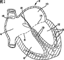
Fig. 2 is substantially the cutaway view of the heart of Fig. 1.
Fig. 3 is the sketch map of the radiation source induction system that can adopt in the present invention.
Fig. 4 is a schematic substantially plane graph, at the conceptive transmitting device that demonstrates the radiation source on the near-end that is used to be connected the radiation source delivery conduit.
Fig. 5 a is the cutaway view that can be used in the far-end of radiation source delivery conduit of the present invention.
Fig. 5 b is the cutaway view of the conduit of Fig. 5 of cutting open along the 5b-5b line.
Fig. 6 is the radiation source conveyer device that can be connected with the radiation source delivery conduit in Fig. 5 a and type shown in the 5b and the perspective view of system.
Fig. 7 a is the cutaway view of the right atrium of human heart, demonstrate have by be arranged on the postcava place or in introducing conduit or sheath insert the into guide line of the preform distal end shape of right atrium.
Fig. 7 b is the cutaway view of the right atrium of human heart, demonstrate have by be arranged on the postcava place or in introducing conduit or sheath insert the into guide line of the preform distal end shape of right atrium.
Fig. 8 has described method and apparatus of the present invention, wherein conduit is inserted in the right atrium along the preform guide line, and be incorporated into source train in the conduit and after advancing to far-end, wherein the wall of they and right atrium closely near or directly press thereon.
Fig. 9 a is the cutaway view of the far-end of another embodiment of implementing conduit of the present invention, and employing can be used for regulating the guide line of shape of the far-end of conduit.
Fig. 9 b demonstrates and forms the far-end of curve shape with the conduit that is pressed against Fig. 9 a on the atrial walls;
Figure 10 a is the sketch map that can combine the far-end of another conduit embodiment of using with the present invention, it adopted can be during entering heart from punctured position extend to stretch or expanded position conduit is pressed in the basket shape layout on the heart wall in the position that will excise.
Figure 10 b is the longitudinal sectional view of the conduit of Figure 10 a of cutting open along the 10b-10b line.
Figure 10 c is the sketch map of the conduit of Figure 10 a, demonstrates the basket that is in stretching, extension or the expanded position.
Figure 11 a is the cutaway view of far-end that can another conduit embodiment used in this invention, and it is used for conduit is remained on self-expanding basket or nest in the desired excision position.
Figure 11 b is the sketch map of the conduit of Figure 11 a, and the sheath introducer is overlapping and pushing described basket.
Figure 11 c is the sketch map of the conduit of Figure 11 b, its mesotheca be pulled the expansion of (or sheath advances) and basket with in desired excision position with conduit support on heart wall.
Figure 12 is the cutaway view of human heart, demonstrates the guide line/conduit with preform distal end shape, is used for being bonded on the atrial walls around one or a plurality of pulmonary venous mouthful, so that the remainder of pulmonary vein and atrial walls is isolated.
Figure 13 a-c demonstrates and implements conduit of the present invention, also comprises the further actuation gear of guide line and guide line.
Figure 14 is the perspective cut-away schematic view of the conduit of employing another inventive aspect relevant with guide line control, and demonstrates guide line curve adaptation section and guide line bending section.
Figure 15 connects the perspective section view that radiation source inner chamber and fluid return the conduit of inner chamber for adopt the inner chamber adapter in the far-end of conduit.
Figure 16 is the cutaway view that is used for reducing the interferential conduit of guide line and radiation excision.
Detailed description of preferred embodiments
Fig. 1 is substantially by the general illustration of the human heart of label 2 expression.In order to understand the present invention better, it is helpful that the knowledge that the physiology and the cardiac cycle of heart comprised the electrobiology that is called as heart is carried out the most basic introduction.
Human heart has four chambers, right atrium 4 that is linked together by valve 8 and right ventricle 6 and the left atrium 10 and the left ventricle 12 that are linked together by valve 14.The function in atrium is used for receiving from venous blood and with its and stores to be used for each heart beating.The blood that exhausts the oxygen branch that returns from the major organs of health and muscle at first flows to right atrium.This blood is fed to right ventricle then, and it will exhaust blood pump that oxygen the divides carbon dioxide of having given emptying and upgrade the lung of oxygen.Again the blood that divides of delivery of supplemental oxygen from lung by left and right pulmonary vein convection current to left ventricle.This again the blood that divides of delivery of supplemental oxygen flow to left ventricle from left atrium, its operation is used for the blood pump that delivery of supplemental oxygen is divided is given the muscle and the organ of health as main pumping chamber.
As the same as described in the front is concise and to the point, when atrium 4 and 6 both when shrinking with compressing blood through the one-way valve 8 between left and right atrium and its corresponding ventricle and 14, heart beating normally begins in right atrium 4.And then after atrial systole, ventricle begins to shrink.One-way valve between atrium and ventricle prevents that blood from refluxing.From another one-way valve of blood process that each ventricle is discharged, this valve is closed after ventricular systole.
The contraction of this coordination of each chamber of heart and order is controlled by the electric system of heart.With reference to Fig. 2, each normal heart beating is a starting point to produce the signal of telecommunication or pulse from the sinuatrial node that is arranged in right atrium 4.This pulse or signal bamboo telegraph are compressed into its corresponding ventricle thereby make them shrink with the blood pressure that will be stored in them through left atrium.The atrium is except isolating in position that is called as atrioventricular node or AV knot 18 and ventricle electricity.The AV knot is used for and will gives ventricle by the electrical signal conduction that sinuatrial node or arbitrary region produced in atrium as electric distribution center.The signal of telecommunication or pulse are very rapidly conducted from the AV knot by the special cells of carrying these pulses gives myocardium of ventricle.These special cells are arranged in the fibre bundle that is called as " Xi Shi bundle " 19 (perhaps the off path of being confirmed, this also treats by " excision ") in the WWP syndrome.The fiber of this Xi Shi bundle finally further is branched into ventricular muscle, and they are called as Purkinje fiber 21 there.This conducting system sends the signal of telecommunication to special ventricular muscle rapidly, thereby makes these ventricular systoles blood pressure is arranged organ and the muscle to lung or health.Therefore, should be understood that how important the correct work of electric system of heart is, and the disorder in electric system should be treated timely and effectively.
According to the present invention, in the output of radiation source, can adopt Norcross, equipment that Georgia sold and system by Novoste Corporationof.Describe in detail among patent below or open application one or more and be presented among Fig. 3 substantially and be called as Beta-Cath
TM" Novoste " system of system, wherein each is all quoted as a reference by this description in full: United States Patent (USP) 5683345; 5899882; 6013020; 6261219; 5967976 and 5529067 and PCT application WO 00/37137 and WO 01/03761.Though the Novoste system is preferred, more broad aspect of the present invention is not limited to this Novoste system, can adopt other to be used near heart tissue or the device in output radiation source contiguously with it.For example, also can use lead or conduit and radiation source or band are arranged on far-end excise heart tissue or form lesion wire with treatment as described arrhythmia here in specific location.
For the ease of initial understanding, Fig. 3 demonstrates the Novoste that can adopt in the present invention with the form of summarizing signal
TMSystem.Demonstrate a slender conduit 20 in Fig. 3, it has a proximal part 22, a distal portions 24 and at least one radiant body that extends betwixt or sends chamber 26.Its size of this conduit be set at by patient vascular system with distal portions be inserted in heart the cut-away area of wanting for example AV knot or other position.This for example can be by utilizing diaphragm paracentesis and catheterization to come percutaneous to insert this conduit and this conduit being advanced enter into right atrium on a common lead 28 and/or left atrium carries out.The lead and the process that are used for making this conduit advance to the excision position are known, will not describe in detail.
In for example above-mentioned percutaneous process, be positioned at the proximal end of the conduit of patient body outside, carry and/or bead or capsule (being also referred to as " seed (seeds) ") that charger 30 is provided for radiation source or a series of radiation source are for example comprised radiative material are loaded in the transmission inner chamber 26 of conduit 20.Also can load additional seed, thereby the length overall of combination seed is at least corresponding to the damaged length that will excise.
After having loaded this radiation source or source train, the liquid that imports pressurization and blood compatibility by the port 34 at the near-end of the transmission inner chamber 26 that is arranged in these radiation source back by fluid supply 32 is sterile saline solution or disinfectant for example.Flow of liquid is pushed these radiation sources to be positioned to the distal portions of the treatment site of wanting through inner chamber along sending inner chamber.Be provided for making the liquid of the power of these radiation sources motions to discharge from the far-end of conduit, but preferred parallel returning in the inner chamber in being located at conduit return, this inner chamber is communicated with the transmission inner chamber at the far-end of conduit.
After radiation source or radiation row are positioned at needed position, allow to stay time enough resection organization.Obviously, provide an elongated and successive basically radiation source though source train is made of independent reflection seed or bead, they can be used for forming the line of the resection organization of passing heart, atrium, wall.These radiation sources are preferably emission β ray, but can also adopt the radiation source of emission gamma-rays, x ray or other ray, and residence time is shorter relatively, following institute in greater detail the number of minutes on.The radioactivity of radiation source and residence time have more the heart tissue thickness that will excise and change and select.Accurate radioactivity and resident between understand fully at present, do not need the program and the known measuring technology of too much test to confirm but can utilize.
After finishing treatment, conduit can be taken out or move to different treatment positions.When the taking-up conduit is removed or moves, preferably make these radiation sources be back to the front device and be subjected to too much radiation to avoid patient.In order to regain these radiation sources, before taking out conduit, can the liquid extruding be passed along opposite direction in case of necessity and send inner chamber so that the treatment element is back to near-end and enters charger.The backflow of liquid can be passed the backflow inner chamber and realizes by push liquid under positive pressure along inverse direction, and it forms a closed-loop path with sending inner chamber, thus along inverse direction to loading attachment 30 these radiation sources of extruding.
Fig. 4 demonstrates a form of loading attachment 30 to help to understand its function and structure with the form of simplifying very much.As here seeing, the loading attachment with preferred conduit has three independent inner chambers: a guidewire lumen 36 is used to hold the heart area of guide line so that catheter guidance extremely will be excised; One sends inner chamber 38, is used to adopt hydraulic mode source train to be pushed the far-end of conductive pipe; And one return inner chamber 40, it the far-end of conduit with send inner chamber and be communicated with, be used for source train is reclaimed into loading attachment.But guide wire lumen can extend through the whole length of conduit or only be passed in distal openings and the distal portions of the conduit between the lateral opening near in the conduit still distal portions at conduit the distal openings.
Source train is made of a plurality of little radiation source or the seed 42 that preloaded advances in the source train inner chamber 43 in radioprotective box 44.Loading attachment 30 comprises a pockets or position 46, and described box 44 can be inserted into wherein.Source train 43 makes seed to discharge and to send to the far-end of conduit along sending inner chamber with aiming at of seed inner chamber 38.For example, the syringe that liquid is housed can be connected on the transmission inner chamber 38 of loading attachment far-end extruding source train seed with conductive pipe.In order after finishing excision, to take out these radiation sources or to change catheter position, syringe or other pressure source can be connected the returning on the inner chamber 40 with along inverse direction extruding liquid stream of this device, thereby make source train return loading attachment and enter box 44.Switching device shifter can be arranged in the loading attachment, thereby can adopt single syringe, and between transmission and backflow inner chamber, switch this fluid when needed.
Fig. 5 a and 5b demonstrate the far-end of the conduit 30 that can adopt in the embodiment of this invention.Conduit has a guidewire lumen 48, send inner chamber 50 with can be with the respective guide line of loading attachment, send and return the transmission inner chamber 50 that inner chamber is connected and return inner chamber 52.This conduit demonstrates the row 54 with the radiation seed 42 that is arranged on far-end.
The length of source train 54 can be chosen as the damage of the excision length that requires on demand.Single radioactivity element or point source are enough to excise or treat the performance that regional area for example changes the AV knot.But, the source train of designated length for form linear cut or scar tissue for example in the MAZE process operable those.Because may need to change the length of source train, so loading attachment can be designed to store the different source train of a plurality of length, thereby the user can reclaim the source train for the needed length of specific excision line, perhaps stores radiation seed so that the user can form the mode of the source train with the different length that require.
Fig. 6 demonstrates to have and is used for sending and the loading attachment 30 in nearest period of the built-in syringe 56 of the source train of withdrawing.Describe this loading attachment that is also referred to as transporter one or more in detail in conjunction with this application patent as a reference with in applying for.
Fig. 7 and 8 demonstrates and adopts the present invention with the vertical lead 58 of preform that is shaped as requested, for example bends to consistently with the heart wall that will excise to think that conduit provides the activity orientation parts.The same shown in Fig. 7 a, at first lead is inserted into by (preferably passing through postcava) in the atrium 4 by conduit or sheath 60, it is arranged to be pressed against (this can identify by the program that is called as mapping) on the atrial walls in the position that will excise there.
As shown in Figure 8, conduit 30 according to the present invention advances above guide line 58 and passes conduit or sheath 60, keeps flat along the heart surface that will excise up to it.After it is inserted into the tram, make the distal advancement (as passing through hydraulic coupling) of radiation seed row conductive pipe, this far-end is pressed against on the atrial walls.Allow the radiation seed row be retained in the far-end up to providing enough radiation dose to damage to excise inner chamber along the residing straight line of distal end of catheter.These radiation seed row can be taken out so that reorientate or take out conduit then.Because radiation source is not in the conduit during importing, locate or recalling, so avoid heart to be subjected to over-radiation.
Fig. 7 b and Fig. 7 a are similar, demonstrate the guide line of optional shape.Fig. 7 b demonstrates a kind of annular, spiral type or pigtail shape lead, can be used for forming around pulmonary vein the excision line.Though be shown as spiral or pigtail shape, also can adopt other suitable shape to form the excision line, and the present invention its more broad aspect be not limited to concrete guide line shape.The same as shown, entering pulmonary venous a kind of method is to enter right atrium (preferably adopt femoral artery path (femoral approach), this path feeds right atrium by postcava), through the atrial septum and enter left atrium and pulmonary vein.Certainly, can adopt other to lead to pulmonary venous path without departing from the scope of the invention.In order to treat atrial fibrillation, guide line or conduit can be configured as successive damage of formation or excision in atrial walls, thereby the remainder of pulmonary vein and left atrium is isolated.Spiral or pigtail shape are for the radiation source conduit being arranged in the pulmonary vein self and particularly useful by pulmonary venous inside or inner surface being exposed to suppress narrow ionizing radiation dose to be treated for the pulmonary venous stenosis.Optionally, the conductor part that is arranged in pulmonary vein can be straight and be positioned at intravenous central authorities substantially.
Can expect that these optional shapes can be used to have the radiation source delivery conduit of far-end of enough flexibilities with consistent with the shape of guide line.The guide line of Fig. 7 a and 7b can for example rustless steel, titanium or Nitinol form by the material of any appropriate.
Optionally, conduit self can have the preform far-end, and for example crooked, pigtail or spiral type are to engage with heart wall in the desired position that is used for excising.Can adopt for example heat setting of known technology, the molded end that makes conduit of waiting to form this shape.Utilize such conduit, lead can be strengthened this conduit during inserting, and extracts this lead out and can make conduit present it to preset shape.To excise the position with radiation source correct be provided be pressed against on the heart wall after, be inserted in the end of conduit into to excise treatment.
Conduit (referring to Fig. 8) also can have electrode or pick off 61, and is for example bipolar, and they are carried on the distal portion office and utilize the conductor connection that extends to the proximal position of patient body outside by conduit.Can consider at least one kind electrode, preferably at least two electrodes or pick off, for example one be positioned near the radiation source and one away from radiation source.Two electrodes or pick off make it possible to sense electric conductivity on the excision line to determine whether excision is finished.Also have, these electrodes make it possible to direct sensing and monitor during excising and/or the electrophysiological characteristics of heart tissue afterwards, and the electrophysiology of drawing out heart simultaneously is to be identified for radiating the appropriate location of excision or treatment.These electrodes can be connected to supervision or the sensing device that is positioned at the patient body outside by one or more conductors that extend through conduit.
In addition, conduit can comprise the cooling surface 63 that is positioned on the distal portions, is used for cooling off selected heart tissue, for example identifies to be used to excise or other radiocurable position that requires.This cooling surface can be based on the Peltier effect, the same disclosed in for example described in front U.S. Patent No. 5529067, and also connect by the one or more conductors that extend through conduit.More particularly, can adopt the system cools of selected heart tissue and on electrophysiology, observe cooling effect and identify the tissue location that to excise or to treat, and in case identify, can by make radiation source pass conduit and arrive described position and do not need to make conduit further motion carry out this treatment immediately.Potential benefit like this is can guarantee better to treat to carry out in desired position.
Fig. 9 a and 9b demonstrate an optional positioning element that is used for setting flexibly and energetically the far-end of radiation delivery conduit 62.The same as shown, conduit 62 comprises that at least one radiation source sends inner chamber 64 and the parallel fluid that extends returns inner chamber 66 between the proximal part of conduit and distal portions.Relative guide line 68 is embedded in or otherwise is connected on the top of conduit, separately 180 °, and extend through the littler guidewire lumen of diameter 70, the length of the conduit that this inner chamber extend through and transmission are parallel with returning inner chamber is so that carry out remote control in the patient body outside.By pushing or unclamping a guide line and draw another guide line, thereby the top of conduit can be with various degree towards being stowed so that the line bending that is pressed against on the heart wall is set, shown in Fig. 9 b, perhaps be used for guide catheter to the position that requires at heart.Above-mentioned conduit also can only adopt single guide line and guidewire lumen, and they will allow only along a direction bending.
Preferably, guide line be not located at radiation source and want between resection organization's line because this can cause attenuation or the disorder in radiation dose distributes.In optional embodiment, guidewire lumen can differently be provided with respect to radiation source and FLUID TRANSPORTATION inner chamber, as shown in figure 16.The conduit here also has four inner chambers: a radiation seed sends or delivery lumen SL; One backflow inner chamber RL, it is rapider so that the littler and seed of pressure is carried that it can be oval-shaped rather than circular; And two littler guidewire lumen WL, their between other two delivery/return inner chambers and with it biasings (aiming at it).These two littler inner chambers are equipped with guide line, and they are connected on the far-end of described conduit and give described conduit bidirectional guiding ability.This guide line can be embedded in the closed distal end of guidewire lumen or otherwise be connected on the far-end of conduit.Basically allow the whole side S (180 °) of conduit to be pressed against on the heart tissue in the structure shown in Figure 16 so that under the situation of not disturbing guide line, excise.All four inner chambers can be used as a whole extrusion molding or can be shaped separately and be welded together and cut off at top end.For two guide lines, each has common operating mechanism in the proximal end of conduit certainly.
Figure 10 a-10c demonstrates another positive location parts of the conduit that is used to adopt expandable cage or basket 72, and it supports the far-end of described conduit 74 and is pressed against on the heart wall that is positioned at the excision position.As shown in figure 10, nest or basket preferably adopt a plurality of elongated members, for example rib or the spoke 76 that extends between a pair of spaced apart fixture 78 on the far-end at described conduit.These securing members 78 can comprise the circumference band of hot shrinkage plastics or other material, preferably are recessed into into the surface of described conduit and think to advance and pass conduit or sheath provides slick substantially surface.These securing members are only keeping each end of these spokes, thereby these spokes must deflection when the bending of described top.These securing members also can be metal or have metal coating, and except the fastening function of rib also as electrode.
According to another possibility of the present invention, these spokes self can be radioactive, for example by applying active material, embedding active material or other technology has radioactivity in them.In this arrangement, these spokes needn't be parallel to each other, but can be with desired patterned arrangement, thus when basket launches to contact with heart wall the excision line of many inclinations of formation in heart.
Figure 11 a-11c demonstrates optional basket or nest or the cage layout that is used for being provided with flexibly catheter tip.In this embodiment, these spokes 76 are by preform or preset in the position shown in Figure 11 c.The sheath or the sleeve 80 that are covered with these spokes hold them in the retracted position, as Figure 11 a with the same shown in the 11b.When or longitudinal pull described sleeve axial along proximal direction, these spokes are exposed out and make these spokes to move to its stretching, extension or expanded position (shown in Figure 11 c), thereby the apical support of conduit is pressed against on the heart wall.
Except rustless steel or plastics, spoke in this embodiment can for example be called as the Nitinol of " Nitinol (nitinol) " sometimes for marmem or plastic components, and it has different performances under different temperatures.For example, can assemble these spokes under low-down temperature and sleeve is arranged on above them, they have very high plasticity and assembling easily under this temperature.Be heated to room temperature or higher after, this metal presents expansion or other state easily, this is specially adapted to make basket or cage device to be configured as to make catheter tip to keep being pressed against on the heart wall or being close to it.In order to remove or reorientate this conduit, sleeve is advanced to hold them in the retracted position on these spokes.
This fixture needn't be expandable cage, but can adopt for example expandable balloon of other fixture, the vacuum ports in catheter wall or anchoring piece that described conduit is fixed on desired position.For example can adopt balloon on the side that is connected conduit (extend less than 360 °, and preferably less than 180 °) that conduit support is pressed against on the heart tissue that will excise round catheter shaft.This conduit seems to be similar to the sort of shown in Figure 11, but replaces spoke and adding the inflation inner chamber that extends and be communicated with this balloon fluid between the near-end of conduit and distal portions with balloon.Perhaps, according to in catheter wall, can be provided with one or more vacuum ports in the similar mode of mode shown in the U.S. Patent No. 6139522 that is employed as a reference.As shown in the superincumbent patent, in the distal portions of conduit, also can use barb, hook or screw wait with conduit be fixed into come close to or in contact with to excise or by heart tissue from the alternate manner treatment of the ionizing radiation of radiation source.
Except above-mentioned feature and function, others of the present invention comprise have than the main body of conduit more the far-end of flexible conduit so that improve navigability and/or reduce tissue injury.Also have, can adopt the conduit that has or do not have guide line.Preform guide line or preshaped catheter can have other shape except pigtail shape or spiral type.
Be known that adopting existing rf ablation technique to excise can cause pulmonary venous stenosis or closure around pulmonary vein.Adopt support to keep this vein to open after reopening this vein carrying out angioplasty in the past, this is unsuccessful sometimes.Other people advises, can adopt Novoste
TMBeta-Cath
TMSystem treats or avoids pulmonary vein by shine this pulmonary vein inside narrow again after carrying out this excision with the ionization radiation.
One or more can being used for of the said equipment treated pulmonary venous restenosis by applying suitable radiant quantity to the excision position.For example, can adopt basket or cage fixed part that the radiation delivery conduit is arranged on the position that requires in the pulmonary vein, and make conduit be close to cut-away area, thereby slow down the growth (principal element in the narrow concomitant injury that blood vessel is caused by angioplasty, support etc.) of scar tissue.Perhaps the radiation source transmitting catheter can adopt pigtail shape or spiral guiding line so that realize identical purpose.
Figure 12 demonstrates conduit of the present invention and launches to form excision line or damage in atrial walls around pulmonary venous mouthful.This conduit can have a preform top, and it forms the big circle or the annulus that must be enough to surround pulmonary venous mouth of its size when guide line is withdrawn.After on the atrial walls around setting is pressed against mouthful, can make to have sufficient length and surround this pulmonary venous damage with formation with the far-end that the radiation source that surrounds described mouthful advances to conduit.Optionally, can adopt shorter radiation source, and the positional cycle variation of this radiation source is up to form complete damage around this mouthful.
Though demonstrate and excise out a line around a pulmonary vein, said method can be used for forming simultaneously lesion wire around many pulmonary vein.
The near-end actuating element 84 that Figure 13 a-c demonstrates the conduit of the present invention 82 with the guide line that is used for changing the distal portions shape and has the actuator 86 that is used for regulating distal end shape.The same as shown, adopt preferred successive line 88.This conduit comprises two guidewire lumen of extending (but can adopt single intra-cavity for two lines) between the far-end that is connected handle on the catheter proximal end and conduit.An end of this line extends through a this inner chamber, and terminates in the far-end of conduit, and it is connected on the top 90 there.Another end of this line extends through another inner chamber and also terminates in the far-end of conduit, and it is connected on the described top there.This guide line holds approximately separately 180 ° of inner chambers, thus on the single line dilatory on another root, unclamp or push simultaneously make the top along the direction deflection that is subjected to backguy.Therefore, this catheter tip can be at the direction upper deflecting different and relative with two as shown in the 13c as Figure 13 b.
For the ease of carrying out the indefiniteness explanation, this guide line controller is shown as rotating pulley or the wheel 92 with relative guide line guide 94 substantially, is held slidably by the described guide line of this guide.Guide line has the retainer 96 that is arranged for the joint of guide when wheel 92 rotates.Adopt this structure, make wheel turns cause drawing single line and unclamping other single line, thereby make the top towards the line bending of being drawn.Make the wheel backward rotation make that the direction of top bending is reverse.
Though this embodiment adopts the line or the cable of joint length to form this two guide lines, should be understood that, can adopt independent line under the situation that does not break away from more broad aspect of the present invention.This guide line structure also is not limited to the radiation source conduit, but can be used in need be by the passage that bends the body any catheter for example in the cardiac catheter.
Figure 14 and 15 demonstrates the supplementary features of the guide line and the distal lumen adapter of change.Figure 15 demonstrates and is not limited to the radiation delivery conduit or is used in the heart excision and can be used in the especially guide line in the cardiac catheter of other conduit, wherein needs the bodily lumen by bending.
Just being used for illustrational is radiation source transmitting catheters at the conduit shown in Figure 15 98, for example described substantially in the above.This conduit is elongated and flexible, and has a proximal part and a distal portions.This conduit comprises a radiation source inner chamber 100 and a backflow inner chamber 102.Solid wire at 104 places extends through guidewire lumen 106 forming guide line 108 substantially, and is crooked and return to form guide line 114 by guidewire lumen 112 round inner chamber adapter 110 at the far-end of conduit.Can be fixed on the distal tip of conduit by binding agent, bonding, interference fit or suitable method round the far-end of the guide line 104 of inner chamber adapter bending, perhaps can otherwise become to fix non-movement relation with the inner chamber adapter so that will send far-end to by the power that guide line applies.Certainly, it is successive that guide line needs not to be, and each guide line 108 and 114 can be independent, and be connected in the far-end of conduit, simultaneously still can be from obtain benefit the various aspects of the present invention shown in Figure 15.Equally, separate about 180 ° though these guidewire lumen are shown as, this also can change the shape that imposes on the bending section of distal end of catheter with change as requested.
The same as shown, a guide line comprises usually by bending section shown in 116 or the crooked section that adapts to.The words of this section necessity can be arranged in two lines.This bending adapts to section 116 and is formed by a plurality of fluctuatings in guide line, and preferred form with a plurality of coils such as disc spring.This section makes can have bigger bending when tension force being applied on other guide line.This bending adapts to section makes this line that the radius of curvature of tighter (littler) can be arranged.It being understood that when guide line 114 is stowed or is applied in tension force in fact the crooked section that adapts to is pushing other guide line, the combination of stretching and compression causes littler radius of curvature.
Comprise another guide line feature at the conduit shown in Figure 15 98, it makes the distal portions of described conduit along the predetermined direction bending.Guide line 108 comprises a bending section 118, engages during its online tension and is pressed against the barrier member 120 that is arranged in inner chamber 106, thereby make this line in the bending of bending section place.In the embodiment illustrated, bending section 118 is substantially V-arrangement, and is positioned near crooked the adaptation section, and the stopper that barrier member has welding or is bonded in inner chamber 106 forms, and guide line 108 extends through this stopper slidably.When the guide line tension, bending section 118 engages and is pressed against on the end of stopper, thereby makes line along the direction bending relative with bending section 118.By this feature, can make conduit in specific location promptly in bending section 118 places bending, and distal end of catheter can keep straight basically to all parts or the some parts of bending section 118.
This bending features certainly is used in the guide line that does not have crooked adaptation section 116.But, by in identical guide line, having two features, thus can so that the distal portions of conduit simultaneously along two different directions bendings, and one of them has less relatively radius of curvature.For example, by dilatory on two guide lines, thereby the joint between bending section 118 and stopper 120 makes far-end along the direction bending relative with bending section.Guide line 114 dilatory makes farther head portion along the direction bending of guide line 114 tensions, and the crooked section 116 that adapts to makes that bending section can have the littler radius of realizing than otherwise of radius.This for example can cause distal portions to extend along a plurality of different directions.For example, distal portions can have at bending section 118 places be substantially L shaped crooked and adapt to section 116 places in bending and have the bending that is substantially C shape.These bendings can be in the identical plane or be in the different planes, thereby provide different shape so that the bodily lumen by complexity or conduit is arranged to press or near the tissue that will treat for the doctor.
Be arranged in described distal end of catheter shown in tubulose U-shaped inner chamber adapter 110 described radiation source and backflow cavity fluid are communicated with.The inner chamber adapter makes the fluid be used for radiation source is transported to distal portions can be back to proximal part.It is preferably metal or rigid plastic construction, and also is used for gaining in strength and stability to the end of conduit.
Those of ordinary skills can understand additional feature and advantage when reading this description, and the application comprises and do not break away from those conspicuous variation and changes that the present invention makes.
Claims (90)
1. method that is used to excise heart tissue, it comprises is subjected to from being positioned near this heart tissue or the ionizing radiation of the ionized radiation source of contact with it described heart tissue.
2. the method for claim 1, wherein described ionized radiation source is elongated and is successive basically, and is formed with cut heart tissue line.
3. the method for claim 1, wherein make described radiation source come close to or in contact with endocardial surface.
4. the method for claim 1, wherein make described radiation source come close to or in contact with epicardial surface.
5. the method for claim 1, wherein make described radiation source keep being close to or contacting the heart tissue that to excise by fixture.
6. the method for claim 1 comprises and the distal portions of slender pipeline is arranged to be close to or to contact the heart tissue that will excise and makes described ionized radiation source pass described conduit advance near the heart tissue that will excise position.
7. the method for claim 1, wherein described method comprises resection organization's line of formation, thereby the remainder of one or more pulmonary vein and left atrium is separated.
8. the method for claim 1, wherein described ionized radiation source is the β radiation source.
9. the method for claim 1 comprises and optionally cools off described heart tissue to identify the tissue that will excise.
10. method as claimed in claim 6, wherein, described conduit comprises the cooling surface that is arranged on the described distal portions, and this method comprises and optionally makes heart tissue contact the tissue that will excise to identify with described cooling surface.
11. the method for claim 1 also comprises the electrophysiological property of the described heart tissue of sensing.
12. method as claimed in claim 6, wherein, described conduit is included in the electrode on the described distal portions, is used for the electrophysiological property of the described heart tissue of sensing.
13. method as claimed in claim 2, wherein, described elongate radiation source comprises a plurality of layouts independent radiation source that is used to form this elongate radiation source in line.
14. method as claimed in claim 13 wherein, makes described elongate radiation source advance along described conduit by fluid pressure.
15. method as claimed in claim 6 wherein, is passed the atrial septum with described conduit insertion.
16. method as claimed in claim 6, wherein, the described distal portions of described conduit has enough flexibilities adapting to the shape of lead, and this method comprises that the described distal portions that makes described conduit advances to the heart tissue that will excise along lead.
17. method as claimed in claim 16, wherein, the described distal portions of described conduit is included in its preform shape that is presented when this distal portions is extracted described lead out.
18. method as claimed in claim 17, wherein, described preform is shaped as spiral type.
19. method as claimed in claim 6 comprises that also the described distal portions with described conduit guides to the heart tissue that will excise.
20. method as claimed in claim 19, wherein, described guiding comprises the shape of regulating described distal portions.
21. method as claimed in claim 6, wherein, the described distal portions of described conduit is remained close to or is contacted the heart tissue that will excise by fixture.
22. the method for the conductive characteristic of an AV knot that is used to change human heart is included in and makes the heart tissue that comprises described AV knot be subjected to ionizing radiation from the ionized radiation source that is close to or contacts this tissue under the situation of this AV knot of incomplete excision.
23. method as claimed in claim 22 comprises conduit is arranged to be close to or to contact the heart tissue that comprises described AV knot, and makes described ionized radiation source pass described conduit to advance near the position of this tissue.
24. method as claimed in claim 22, wherein, described ionized radiation source is the β radiation source.
25. method as claimed in claim 22, wherein, the conductive characteristic that changes described AV knot is with the treatment reciprocal tachycardia.
26. method as claimed in claim 22, wherein, described radiation source keeps being close to or contacting the described heart tissue that comprises described AV knot by fixture.
27. method as claimed in claim 22 comprises and optionally cools off described heart tissue to identify the tissue that will treat.
28. method as claimed in claim 23, wherein, described conduit comprises the cooling surface that is arranged on the described distal portions, and this method comprises and optionally makes heart tissue contact the tissue that will treat to identify with described cooling surface.
29. an equipment that is used for the treatment of heart tissue, it comprises: slender conduit, and this slender conduit comprises near-end and distal portions, and is formed with the passage that extends between these end parts, this passage is used for holding ionized radiation source along it; And the remote control unit that is used to change described distal portions or its a part of shape.
30. equipment as claimed in claim 29, wherein, described remote control unit is included in the guide line that extends through described conduit between described proximal part and the distal portions.
31. equipment as claimed in claim 29, wherein, described remote control unit comprises two guide lines that extend through described conduit between described proximal part and distal portions.
32. equipment as claimed in claim 29, wherein, described remote control unit comprises a fixture, and this fixture is carried on the described distal portion office of described conduit, and is used for described conduit is kept being pressed against on the endocardial surface.
33. equipment as claimed in claim 29, wherein, described fixture can be used to insert the retracted position of described conduit and be used for described conduit is remained between the extended position of desired position and move.
34. equipment as claimed in claim 29, wherein, described fixture comprises a plurality of ribs, and these ribs extend substantially abreast with the conduit that is in during inserting in the retracted position, and can move to extended position so that described conduit is remained on desired position.
35. equipment as claimed in claim 34, wherein, described rib is arranged in the distal portions of described conduit and leaves conduit when crooked and move to extended position, and described conduit comprises remote-controlled backguy, is used for making the distal portions bending of described conduit.
36. equipment as claimed in claim 34, wherein, described rib is biased to the normal extension position, but described conduit comprises the sleeve pipe of the axially-movable on the distal portions that is arranged on described conduit, and this sleeve pipe can move between the second position that covers described rib and keep the primary importance of their contiguous described conduits and allow described rib to stretch.
37. equipment as claimed in claim 34, wherein, described rib comprises shape-memory material, and this rib is provided in and is in body temperature following time and presents extended configuration.
38. equipment as claimed in claim 29 also comprises at least one electrode of the described distal portion office that is positioned at described conduit, is used for the electrophysiological property of sensing heart tissue.
39. equipment as claimed in claim 38 comprises at least two isolated electrodes.
40. equipment as claimed in claim 33, wherein, described fixture comprises an inflatable part.
41. equipment as claimed in claim 33, wherein, described conduit is included in the inflation inner chamber that extends between described proximal part and the described distal portions, and described fixture comprises the balloon that is carried on described distal portion office and is communicated with described inflation inner chamber.
42. equipment as claimed in claim 41, wherein, described balloon extends less than 360 ° around described catheter shaft.
43. equipment as claimed in claim 29 also comprises the ionized radiation source that is arranged in described passage.
44. equipment as claimed in claim 29, also be included in extend between described proximal part and the distal portions and with the backward channel of radiation source channel connection in described distal portions, this radiation source comprises at least one radiation seed, and this radiation seed can advance along described radiation source passage to far-end and under the distal-to-proximal fluidic effect that circulates of described backward channel at the near-end from described radiation source passage.
45. equipment as claimed in claim 29 also comprises the distal portions or its a part of guide wire channel that extend through described at least conduit.
46. equipment as claimed in claim 32, wherein, described fixture comprises the one or more pump orifices that are used to be adsorbed on the heart surface.
47. equipment as claimed in claim 32, wherein, described fixture comprises the one or more anchoring pieces that are used for engaging heart surface and keep described distal portions.
48. be used for the treatment of the equipment of heart tissue, it comprises flexible slender conduit, this conduit has a proximal part and a distal portions, and be formed with the passage that between described near-end and distal portions, extends, this passage is used for passing through ionized radiation source along it, the described distal portions of described conduit is formed with the preform part, and this preform partly is provided for engaging described heart tissue in desired position.
49. equipment as claimed in claim 48, wherein, described preform is a spiral type partly, is used to contact pulmonary venous inner surface.
50. equipment as claimed in claim 48, wherein, the distal portions of described conduit has enough flexibilities adapting to the shape of lead, and this method comprises that the described distal portions that makes described conduit advances to the heart tissue that will treat along guide line.
51. equipment as claimed in claim 50, wherein, the described preform part of described conduit is presenting described preform shape when distal portions is extracted described lead out.
52. the chamber that is used for being inserted into human heart is treated the equipment of heart tissue, this equipment comprises: flexible elongated member, and it has a proximal part and a distal portions; Fixture, it can move being used to insert the retracted position of described parts and being used for making described distal portions to remain between the extended position of the position that requires in the heart, described fixture comprises an ionized radiation source, is used for the treatment of the heart tissue that comes close to or in contact with described radiation source.
53. equipment as claimed in claim 52, wherein, described fixture comprises a plurality of ribs, these ribs extend substantially abreast with the described elongated member that is in the retracted position, and can move to extended position so that described parts are remained in the desired position, described ionized radiation source is positioned on described rib one or more.
54. equipment as claimed in claim 53, wherein, described ionized radiation source is the β ray emitter.
55. a method for the treatment of atrial fibrillation, it comprises:
By making selected heart tissue be subjected to coming in the wall of left atrium, to form many resection organization's lines from the ionizing radiation of the ionized radiation source that comes close to or in contact with selected tissue.
56. method as claimed in claim 55, wherein, described ionized radiation source is elongated and successive basically.
57. method as claimed in claim 55 wherein, makes described radiation source be close to or contact endocardial surface.
58. method as claimed in claim 55 wherein, makes described radiation source be close to or contact epicardial surface.
59. method as claimed in claim 57 wherein, makes described radiation source keep being close to or contacting the heart tissue that will excise by a fixture.
60. method as claimed in claim 55 comprises the distal portions of slender conduit is arranged to be close to or contact the heart tissue that will excise, and makes described ionized radiation source pass described conduit to advance near the heart tissue that will excise position.
61. method as claimed in claim 55, wherein, described ionized radiation source is the β radiation source.
62. method as claimed in claim 56, wherein, described elongate radiation source comprises a plurality of independent radiation sources that are used to form described elongate radiation source that are provided with in line.
63. method as claimed in claim 60, wherein, advance along described conduit under fluid pressure in described elongate radiation source.
64. a method that is used for the treatment of pulmonary venous stenosis comprises described pulmonary venous inner surface is subjected to from the ionizing radiation that comes close to or in contact with this surperficial ionized radiation source.
65. as the described method of claim 64, wherein, described ionized radiation source is elongated and is successive basically.
66. as the described method of claim 64, comprise and the distal portions of slender conduit be arranged to be close to or contact described pulmonary venous inner surface, and make described ionized radiation source pass described conduit to advance near the tissue that to treat position.
67. as the described method of claim 64, wherein, described ionized radiation source is the β radiation source.
68. as the described method of claim 65, wherein, described radiation source comprises a plurality of independent radiation sources that are used to form described elongate radiation source that are provided with in line.
69. as the described method of claim 66, wherein, described radiation source advances along described conduit under fluid pressure.
70., wherein, described atrial septum is passed in described conduit insertion as the described method of claim 66.
71. as the described method of claim 66, wherein, the described distal portions of described conduit has enough flexibilities adapting to the shape of guide line, and this method comprises that the described distal portions that makes described conduit advances to described pulmonary venous inside along a guide line.
72. as the described method of claim 71, wherein, the described distal portions of described conduit is included in its preform shape that is presented when this distal portions is extracted described guide line out.
73. as the described method of claim 72, wherein, described preform is shaped as spiral type.
74. flexible slender conduit, it comprises a distal portions and a proximal part, and first and second inner chambers that between described proximal part and distal portions, extend, described first inner chamber be used for being contained in extend between described proximal part and the distal portions and be fixed on described supravasal guide line at described distal portions, described second inner chamber be used to be contained in extend between described proximal part and the distal portions and be fixed on described supravasal guide line in described distal portion office, at least one described guide line comprises the crooked section that adapts to, and is used for adapting to when the near-end to guide line pushes or pulls near the bending of conduit this section.
75. as the described conduit of claim 74, wherein, described guide line comprises from described near-end and extends to described distal portions and extend to single slender threads of described proximal part by described second inner chamber by described first inner chamber that this slender threads is successive in the described distal portions of described conduit.
76. as the described conduit of claim 74, wherein, described guide line comprises independent line.
77. as the described conduit of claim 74, wherein, in the described line one comprises a bending section in described distal portions, and the described inner chamber that holds comprises and being used at dilatory described line so that the distal portions of this line and described conduit engages the barrier member of described bending section when presenting curved shape.
78. as the described conduit of claim 77, wherein, described bending section is arranged in identical inner chamber with the described crooked section that adapts to.
79. as the described conduit of claim 75, wherein, described conduit is included in third and fourth inner chamber that extends between described proximal part and the distal portions.
80. as the described conduit of claim 79, wherein, described conduit comprises a U-shaped inner chamber adapter in described distal portions, this adapter connects described third and fourth inner chamber with the relation that fluid is communicated with.
81. as the described conduit of claim 77, wherein, described bending section is near described barrier member.
82. as the described conduit of claim 81, wherein, the described crooked section that adapts to comprises a plurality of fluctuatings that are formed in the described line.
83. as the described conduit of claim 82, wherein, the described crooked section that adapts to comprises a plurality of pitch of the laps that are formed in the described line.
84. as the described conduit of claim 77, wherein, described bending section is included in the section that is substantially U-shaped or V-arrangement in the described line.
85. flexible slender conduit, it comprises a distal portions and a proximal part, and first and second inner chambers that between described proximal part and distal portions, extend, described first inner chamber be used for being contained in extend between described proximal part and the distal portions and be fixed on described supravasal guide line at described distal portions, described second inner chamber be used to be contained in extend between described proximal part and the distal portions and be fixed on described supravasal guide line in described distal portion office, at least one described guide line comprises a bending section in described distal portions, and the described inner chamber that holds comprises and being used at dilatory described line so that the distal portions of described conduit engages the barrier member of described bending section when presenting curved shape.
86. as the described conduit of claim 85, wherein, described guide line comprises a single slender threads, this list slender threads extends to described distal portions and extends to described proximal part by described second inner chamber by described first inner chamber from described near-end, and described slender threads is successive in the distal portions of described conduit.
87. as the described conduit of claim 85, wherein, described guide line comprises independent line.
88. as the described conduit of claim 85, wherein, described conduit is included in third and fourth inner chamber that extends between described proximal part and the distal portions.
89. as the described conduit of claim 88, wherein, described conduit comprises a U-shaped inner chamber adapter in described distal portions, this adapter is used for connecting described third and fourth inner chamber with the relation that is communicated with.
90. as the described conduit of claim 85, wherein, described bending section is included in the section that is substantially U-shaped or V-arrangement in the described line.
Applications Claiming Priority (2)
| Application Number | Priority Date | Filing Date | Title |
|---|---|---|---|
| US32429901P | 2001-09-24 | 2001-09-24 | |
| US60/324,299 | 2001-09-24 |
Publications (1)
| Publication Number | Publication Date |
|---|---|
| CN1556719A true CN1556719A (en) | 2004-12-22 |
Family
ID=23262994
Family Applications (1)
| Application Number | Title | Priority Date | Filing Date |
|---|---|---|---|
| CNA028186001A Pending CN1556719A (en) | 2001-09-24 | 2002-09-23 | Methods and apparatus employing ionizing radiation for treatment of cardiac arrhythmia |
Country Status (7)
| Country | Link |
|---|---|
| US (3) | US7182725B2 (en) |
| EP (1) | EP1429649A4 (en) |
| JP (1) | JP2005532832A (en) |
| CN (1) | CN1556719A (en) |
| AU (1) | AU2002331891A1 (en) |
| CA (1) | CA2460174A1 (en) |
| WO (1) | WO2003026480A2 (en) |
Cited By (13)
| Publication number | Priority date | Publication date | Assignee | Title |
|---|---|---|---|---|
| CN1911471B (en) * | 2005-08-02 | 2012-07-18 | 韦伯斯特生物官能公司 | System for treating atrial fibrillation |
| CN103635226A (en) * | 2011-02-10 | 2014-03-12 | Dc设备公司 | Apparatus and methods to create and maintain an intra-atrial pressure relief opening |
| US9205236B2 (en) | 2011-12-22 | 2015-12-08 | Corvia Medical, Inc. | Methods, systems, and devices for resizable intra-atrial shunts |
| US9232997B2 (en) | 2006-11-07 | 2016-01-12 | Corvia Medical, Inc. | Devices and methods for retrievable intra-atrial implants |
| US9277995B2 (en) | 2010-01-29 | 2016-03-08 | Corvia Medical, Inc. | Devices and methods for reducing venous pressure |
| US9358371B2 (en) | 2006-11-07 | 2016-06-07 | Corvia Medical, Inc. | Intra-atrial implants made of non-braided material |
| US9456812B2 (en) | 2006-11-07 | 2016-10-04 | Corvia Medical, Inc. | Devices for retrieving a prosthesis |
| CN104703556B (en) * | 2012-08-28 | 2017-05-24 | 波士顿科学西美德公司 | Renal RF ablation system with a movable virtual electrode and related methods of use |
| US9757107B2 (en) | 2009-09-04 | 2017-09-12 | Corvia Medical, Inc. | Methods and devices for intra-atrial shunts having adjustable sizes |
| US10413284B2 (en) | 2006-11-07 | 2019-09-17 | Corvia Medical, Inc. | Atrial pressure regulation with control, sensing, monitoring and therapy delivery |
| US10568751B2 (en) | 2006-11-07 | 2020-02-25 | Corvia Medical, Inc. | Devices and methods for coronary sinus pressure relief |
| US10632292B2 (en) | 2014-07-23 | 2020-04-28 | Corvia Medical, Inc. | Devices and methods for treating heart failure |
| US10675450B2 (en) | 2014-03-12 | 2020-06-09 | Corvia Medical, Inc. | Devices and methods for treating heart failure |
Families Citing this family (54)
| Publication number | Priority date | Publication date | Assignee | Title |
|---|---|---|---|---|
| US8414543B2 (en) | 1999-10-22 | 2013-04-09 | Rex Medical, L.P. | Rotational thrombectomy wire with blocking device |
| US7128739B2 (en) | 2001-11-02 | 2006-10-31 | Vivant Medical, Inc. | High-strength microwave antenna assemblies and methods of use |
| US6878147B2 (en) | 2001-11-02 | 2005-04-12 | Vivant Medical, Inc. | High-strength microwave antenna assemblies |
| EP1551509B1 (en) * | 2002-09-10 | 2008-10-29 | Cianna Medical, Inc. | Brachytherapy apparatus |
| US6889695B2 (en) * | 2003-01-08 | 2005-05-10 | Cyberheart, Inc. | Method for non-invasive heart treatment |
| US7311703B2 (en) | 2003-07-18 | 2007-12-25 | Vivant Medical, Inc. | Devices and methods for cooling microwave antennas |
| US10182734B2 (en) | 2003-07-18 | 2019-01-22 | Biosense Webster, Inc. | Enhanced ablation and mapping catheter and method for treating atrial fibrillation |
| US7438714B2 (en) * | 2003-09-12 | 2008-10-21 | Boston Scientific Scimed, Inc. | Vacuum-based catheter stabilizer |
| US20050171396A1 (en) * | 2003-10-20 | 2005-08-04 | Cyberheart, Inc. | Method for non-invasive lung treatment |
| EP1691747B1 (en) * | 2003-11-13 | 2012-05-23 | CardioPolymers, Inc. | Control of cardiac arrhythmias by modification of neuronal conduction within fat pads of the heart |
| US8073538B2 (en) | 2003-11-13 | 2011-12-06 | Cardio Polymers, Inc. | Treatment of cardiac arrhythmia by modification of neuronal signaling through fat pads of the heart |
| US7662082B2 (en) | 2004-11-05 | 2010-02-16 | Theragenics Corporation | Expandable brachytherapy device |
| US7618362B2 (en) * | 2005-03-28 | 2009-11-17 | Boston Scientific Scimed, Inc. | Spacer apparatus for radiation and ablation therapy |
| US7799019B2 (en) | 2005-05-10 | 2010-09-21 | Vivant Medical, Inc. | Reinforced high strength microwave antenna |
| US7998139B2 (en) * | 2007-04-25 | 2011-08-16 | Vivant Medical, Inc. | Cooled helical antenna for microwave ablation |
| US8353901B2 (en) | 2007-05-22 | 2013-01-15 | Vivant Medical, Inc. | Energy delivery conduits for use with electrosurgical devices |
| US9023024B2 (en) | 2007-06-20 | 2015-05-05 | Covidien Lp | Reflective power monitoring for microwave applications |
| US8652022B2 (en) * | 2007-09-10 | 2014-02-18 | Boston Scientific Scimed, Inc. | Stabilizer and method for irradiating tumors |
| WO2009042842A1 (en) | 2007-09-26 | 2009-04-02 | Cyberheart, Inc. | Radiosurgical ablation of the myocardium |
| US20090216187A1 (en) * | 2008-02-22 | 2009-08-27 | Walter Wohlgemuth | Method of Treatment of Vascular Diseases |
| US20090230167A1 (en) * | 2008-03-17 | 2009-09-17 | Medtronic Vascular, Inc. | Endostapler Biasing Mechanism |
| US8585695B2 (en) * | 2008-07-22 | 2013-11-19 | Hue-Teh Shih | Systems and methods for noncontact ablation |
| US20100331834A1 (en) * | 2009-06-29 | 2010-12-30 | Vivant Medical,Inc. | Ablation Probe Fixation |
| US8475372B2 (en) | 2010-10-29 | 2013-07-02 | Medtronic Vascular, Inc. | Implantable medical sensor and fixation system |
| US8864676B2 (en) | 2010-10-29 | 2014-10-21 | Medtronic Vascular, Inc. | Implantable medical sensor and fixation system |
| US8727996B2 (en) | 2011-04-20 | 2014-05-20 | Medtronic Vascular, Inc. | Delivery system for implantable medical device |
| US9592091B2 (en) | 2011-08-30 | 2017-03-14 | Biosense Webster (Israel) Ltd. | Ablation catheter for vein anatomies |
| US20130116496A1 (en) * | 2011-11-04 | 2013-05-09 | Ron Waksman | Apparatus and method for radiation treatment of a desired area in the renal vascular system of a patient |
| US9861802B2 (en) * | 2012-08-09 | 2018-01-09 | University Of Iowa Research Foundation | Catheters, catheter systems, and methods for puncturing through a tissue structure |
| US9351648B2 (en) | 2012-08-24 | 2016-05-31 | Medtronic, Inc. | Implantable medical device electrode assembly |
| WO2014153257A2 (en) * | 2013-03-14 | 2014-09-25 | Dragan Nebrigic | Treating and detecting biologic targets such as infectious diseases |
| EP3091921B1 (en) | 2014-01-06 | 2019-06-19 | Farapulse, Inc. | Apparatus for renal denervation ablation |
| EP4238521A3 (en) | 2014-05-07 | 2023-11-29 | Farapulse, Inc. | Methods and apparatus for selective tissue ablation |
| EP3154463B1 (en) | 2014-06-12 | 2019-03-27 | Farapulse, Inc. | Apparatus for rapid and selective transurethral tissue ablation |
| WO2015192018A1 (en) | 2014-06-12 | 2015-12-17 | Iowa Approach Inc. | Method and apparatus for rapid and selective tissue ablation with cooling |
| EP3206613B1 (en) | 2014-10-14 | 2019-07-03 | Farapulse, Inc. | Apparatus for rapid and safe pulmonary vein cardiac ablation |
| CR20170245A (en) | 2014-12-05 | 2017-09-14 | Edwards Lifesciences Corp | DIRIGIBLE CATETER WITH TRACTION CABLE |
| US10130423B1 (en) | 2017-07-06 | 2018-11-20 | Farapulse, Inc. | Systems, devices, and methods for focal ablation |
| US10660702B2 (en) | 2016-01-05 | 2020-05-26 | Farapulse, Inc. | Systems, devices, and methods for focal ablation |
| US10172673B2 (en) | 2016-01-05 | 2019-01-08 | Farapulse, Inc. | Systems devices, and methods for delivery of pulsed electric field ablative energy to endocardial tissue |
| US20170189097A1 (en) | 2016-01-05 | 2017-07-06 | Iowa Approach Inc. | Systems, apparatuses and methods for delivery of ablative energy to tissue |
| EP3471631A4 (en) | 2016-06-16 | 2020-03-04 | Farapulse, Inc. | Systems, apparatuses, and methods for guide wire delivery |
| US9987081B1 (en) | 2017-04-27 | 2018-06-05 | Iowa Approach, Inc. | Systems, devices, and methods for signal generation |
| US10617867B2 (en) | 2017-04-28 | 2020-04-14 | Farapulse, Inc. | Systems, devices, and methods for delivery of pulsed electric field ablative energy to esophageal tissue |
| WO2019002942A1 (en) * | 2017-06-30 | 2019-01-03 | Avectas Limited | Electrospray catheter |
| EP3681391A1 (en) | 2017-09-12 | 2020-07-22 | Farapulse, Inc. | Systems, apparatuses, and methods for ventricular focal ablation |
| CN112087978B (en) | 2018-05-07 | 2023-01-17 | 波士顿科学医学有限公司 | Epicardial ablation catheter |
| CN112118798A (en) | 2018-05-07 | 2020-12-22 | 法拉普尔赛股份有限公司 | Systems, devices, and methods for filtering high voltage noise induced by pulsed electric field ablation |
| CN112087980B (en) | 2018-05-07 | 2023-01-10 | 波士顿科学医学有限公司 | Systems, devices, and methods for delivering ablation energy to tissue |
| WO2020061359A1 (en) | 2018-09-20 | 2020-03-26 | Farapulse, Inc. | Systems, apparatuses, and methods for delivery of pulsed electric field ablative energy to endocardial tissue |
| US10625080B1 (en) | 2019-09-17 | 2020-04-21 | Farapulse, Inc. | Systems, apparatuses, and methods for detecting ectopic electrocardiogram signals during pulsed electric field ablation |
| US11065047B2 (en) | 2019-11-20 | 2021-07-20 | Farapulse, Inc. | Systems, apparatuses, and methods for protecting electronic components from high power noise induced by high voltage pulses |
| US11497541B2 (en) | 2019-11-20 | 2022-11-15 | Boston Scientific Scimed, Inc. | Systems, apparatuses, and methods for protecting electronic components from high power noise induced by high voltage pulses |
| US10842572B1 (en) | 2019-11-25 | 2020-11-24 | Farapulse, Inc. | Methods, systems, and apparatuses for tracking ablation devices and generating lesion lines |
Family Cites Families (83)
| Publication number | Priority date | Publication date | Assignee | Title |
|---|---|---|---|---|
| US54349A (en) * | 1866-05-01 | David houstel | ||
| US4441945A (en) * | 1979-01-12 | 1984-04-10 | Hoechst Aktiengesellschaft | Method for selective lamination of thermoplastic layers |
| US4378224A (en) * | 1980-09-19 | 1983-03-29 | Nimni Marcel E | Coating for bioprosthetic device and method of making same |
| US4323358A (en) * | 1981-04-30 | 1982-04-06 | Vascor, Inc. | Method for inhibiting mineralization of natural tissue during implantation |
| FR2523810B1 (en) * | 1982-03-23 | 1988-11-25 | Carpentier Alain | ORGANIC GRAFT FABRIC AND PROCESS FOR ITS PREPARATION |
| US4979951A (en) * | 1984-05-30 | 1990-12-25 | Simpson John B | Atherectomy device and method |
| US4553974A (en) * | 1984-08-14 | 1985-11-19 | Mayo Foundation | Treatment of collagenous tissue with glutaraldehyde and aminodiphosphonate calcification inhibitor |
| US4785795A (en) * | 1985-07-15 | 1988-11-22 | Abiomed Cardiovascular, Inc. | High-frequency intra-arterial cardiac support system |
| US4769032A (en) * | 1986-03-05 | 1988-09-06 | Bruce Steinberg | Prosthetic valve and monitoring system and method |
| US4762130A (en) * | 1987-01-15 | 1988-08-09 | Thomas J. Fogarty | Catheter with corkscrew-like balloon |
| US4784636A (en) * | 1987-04-30 | 1988-11-15 | Schneider-Shiley (U.S.A.) Inc. | Balloon atheroectomy catheter |
| US4819751A (en) * | 1987-10-16 | 1989-04-11 | Baxter Travenol Laboratories, Inc. | Valvuloplasty catheter and method |
| US5026367A (en) * | 1988-03-18 | 1991-06-25 | Cardiovascular Laser Systems, Inc. | Laser angioplasty catheter and a method for use thereof |
| US4886067A (en) * | 1989-01-03 | 1989-12-12 | C. R. Bard, Inc. | Steerable guidewire with soft adjustable tip |
| US5002566A (en) * | 1989-02-17 | 1991-03-26 | Baxter International Inc. | Calcification mitigation of bioprosthetic implants |
| US5051401A (en) * | 1989-04-07 | 1991-09-24 | University Of South Alabama | Inhibition of mineral deposition by phosphorylated and related polyanionic peptides |
| US5009659A (en) * | 1989-10-30 | 1991-04-23 | Schneider (Usa) Inc. | Fiber tip atherectomy catheter |
| US5092873A (en) * | 1990-02-28 | 1992-03-03 | Devices For Vascular Intervention, Inc. | Balloon configuration for atherectomy catheter |
| US5267960A (en) * | 1990-03-19 | 1993-12-07 | Omnitron International Inc. | Tissue engaging catheter for a radioactive source wire |
| US5100424A (en) * | 1990-05-21 | 1992-03-31 | Cardiovascular Imaging Systems, Inc. | Intravascular catheter having combined imaging abrasion head |
| US5078722A (en) * | 1990-08-14 | 1992-01-07 | Cordis Corporation | Method and apparatus for removing deposits from a vessel |
| US5484384A (en) * | 1991-01-29 | 1996-01-16 | Med Institute, Inc. | Minimally invasive medical device for providing a radiation treatment |
| US5295958A (en) * | 1991-04-04 | 1994-03-22 | Shturman Cardiology Systems, Inc. | Method and apparatus for in vivo heart valve decalcification |
| US6183469B1 (en) * | 1997-08-27 | 2001-02-06 | Arthrocare Corporation | Electrosurgical systems and methods for the removal of pacemaker leads |
| US5263493A (en) * | 1992-02-24 | 1993-11-23 | Boaz Avitall | Deflectable loop electrode array mapping and ablation catheter for cardiac chambers |
| US5281213A (en) * | 1992-04-16 | 1994-01-25 | Implemed, Inc. | Catheter for ice mapping and ablation |
| US5309910A (en) | 1992-09-25 | 1994-05-10 | Ep Technologies, Inc. | Cardiac mapping and ablation systems |
| EP0605796B1 (en) * | 1992-12-04 | 2003-08-13 | C.R. Bard, Inc. | Catheter with independent proximal and distal control |
| US5364352A (en) * | 1993-03-12 | 1994-11-15 | Heart Rhythm Technologies, Inc. | Catheter for electrophysiological procedures |
| US5715817A (en) * | 1993-06-29 | 1998-02-10 | C.R. Bard, Inc. | Bidirectional steering catheter |
| ATE184496T1 (en) | 1993-07-01 | 1999-10-15 | Schneider Europ Gmbh | MEDICAL DEVICES FOR THE TREATMENT OF BLOOD VESSELS USING IONIZATION RADIATION |
| US5540659A (en) * | 1993-07-15 | 1996-07-30 | Teirstein; Paul S. | Irradiation catheter and method of use |
| US5454795A (en) * | 1994-06-27 | 1995-10-03 | Target Therapeutics, Inc. | Kink-free spiral-wound catheter |
| US5680860A (en) * | 1994-07-07 | 1997-10-28 | Cardiac Pathways Corporation | Mapping and/or ablation catheter with coilable distal extremity and method for using same |
| US5885278A (en) | 1994-10-07 | 1999-03-23 | E.P. Technologies, Inc. | Structures for deploying movable electrode elements |
| US5683345A (en) * | 1994-10-27 | 1997-11-04 | Novoste Corporation | Method and apparatus for treating a desired area in the vascular system of a patient |
| US6503185B1 (en) * | 1994-10-27 | 2003-01-07 | Novoste Corporation | Method and apparatus for treating a desired area in the vascular system of a patient |
| US5899882A (en) * | 1994-10-27 | 1999-05-04 | Novoste Corporation | Catheter apparatus for radiation treatment of a desired area in the vascular system of a patient |
| US6023638A (en) * | 1995-07-28 | 2000-02-08 | Scimed Life Systems, Inc. | System and method for conducting electrophysiological testing using high-voltage energy pulses to stun tissue |
| EP0847249A4 (en) | 1995-08-24 | 2004-09-29 | Medtronic Ave Inc | X-ray catheter |
| US5925038A (en) | 1996-01-19 | 1999-07-20 | Ep Technologies, Inc. | Expandable-collapsible electrode structures for capacitive coupling to tissue |
| US5891136A (en) | 1996-01-19 | 1999-04-06 | Ep Technologies, Inc. | Expandable-collapsible mesh electrode structures |
| US5755761A (en) * | 1996-04-26 | 1998-05-26 | Pharmatarget, Inc. | Atrial pacing catheter and method having multiple electrodes in the right atrium and coronary sinus |
| BR9710160A (en) * | 1996-09-23 | 1999-07-27 | Novoste Corp | Treatment system with intraluminal irradiation |
| US5924973A (en) | 1996-09-26 | 1999-07-20 | The Trustees Of Columbia University In The City Of New York | Method of treating a disease process in a luminal structure |
| US6311692B1 (en) | 1996-10-22 | 2001-11-06 | Epicor, Inc. | Apparatus and method for diagnosis and therapy of electrophysiological disease |
| US6840936B2 (en) | 1996-10-22 | 2005-01-11 | Epicor Medical, Inc. | Methods and devices for ablation |
| US6058323A (en) | 1996-11-05 | 2000-05-02 | Lemelson; Jerome | System and method for treating select tissue in a living being |
| US6030360A (en) * | 1996-12-30 | 2000-02-29 | Biggs; Robert C. | Steerable catheter |
| US6213974B1 (en) * | 1996-12-30 | 2001-04-10 | Visionary Biomedical, Inc. | Steerable catheter having segmented tip and one-piece inlet housing, and method of fabricating same |
| US6063078A (en) * | 1997-03-12 | 2000-05-16 | Medtronic, Inc. | Method and apparatus for tissue ablation |
| US6488673B1 (en) | 1997-04-07 | 2002-12-03 | Broncus Technologies, Inc. | Method of increasing gas exchange of a lung |
| US6019718A (en) * | 1997-05-30 | 2000-02-01 | Scimed Life Systems, Inc. | Apparatus for intravascular radioactive treatment |
| US6966908B2 (en) | 1997-07-08 | 2005-11-22 | Atrionix, Inc. | Tissue ablation device assembly and method for electrically isolating a pulmonary vein ostium from an atrial wall |
| US6997925B2 (en) | 1997-07-08 | 2006-02-14 | Atrionx, Inc. | Tissue ablation device assembly and method for electrically isolating a pulmonary vein ostium from an atrial wall |
| US5816999A (en) * | 1997-07-24 | 1998-10-06 | Bischoff; Jeffrey | Flexible catheter for the delivery of ionizing radiation to the interior of a living body |
| US5913813A (en) * | 1997-07-24 | 1999-06-22 | Proxima Therapeutics, Inc. | Double-wall balloon catheter for treatment of proliferative tissue |
| US6123699A (en) * | 1997-09-05 | 2000-09-26 | Cordis Webster, Inc. | Omni-directional steerable catheter |
| ATE227145T1 (en) | 1997-09-26 | 2002-11-15 | Schneider Europ Gmbh | BALLOON CATHETER INFLATED WITH CARBON DIOXIDE FOR RADIOTHERAPY |
| US6267760B1 (en) * | 1998-05-05 | 2001-07-31 | Scimed Life Systems, Inc. | Surgical method and apparatus for positioning a diagnostic or therapeutic element within the body and forming an incision in tissue with minimal blood loss |
| US6120476A (en) * | 1997-12-01 | 2000-09-19 | Cordis Webster, Inc. | Irrigated tip catheter |
| US6299596B1 (en) * | 1998-03-20 | 2001-10-09 | Schneider (Usa) Inc. | Method of bonding polymers and medical devices comprising materials bonded by said method |
| US6047700A (en) * | 1998-03-30 | 2000-04-11 | Arthrocare Corporation | Systems and methods for electrosurgical removal of calcified deposits |
| AU748225B2 (en) * | 1998-05-04 | 2002-05-30 | Novoste Corporation | Intraluminal radiation treatment system |
| US6050930A (en) * | 1998-06-02 | 2000-04-18 | Teirstein; Paul S. | Irradiation catheter with expandable source |
| US6004310A (en) * | 1998-06-17 | 1999-12-21 | Target Therapeutics, Inc. | Multilumen catheter shaft with reinforcement |
| US6217565B1 (en) * | 1998-07-16 | 2001-04-17 | Mark Cohen | Reinforced variable stiffness tubing |
| US6254601B1 (en) | 1998-12-08 | 2001-07-03 | Hysterx, Inc. | Methods for occlusion of the uterine arteries |
| US6224536B1 (en) | 1999-02-08 | 2001-05-01 | Advanced Cardiovascular Systems | Method for delivering radiation therapy to an intravascular site in a body |
| US8636648B2 (en) | 1999-03-01 | 2014-01-28 | West View Research, Llc | Endoscopic smart probe |
| US6366808B1 (en) | 2000-03-13 | 2002-04-02 | Edward A. Schroeppel | Implantable device and method for the electrical treatment of cancer |
| US6738663B2 (en) | 1999-04-09 | 2004-05-18 | Oncostim, A Minnesota Corporation | Implantable device and method for the electrical treatment of cancer |
| US6333020B1 (en) | 1999-05-13 | 2001-12-25 | Micro Therapeutics, Inc. | Methods for treating AVM's using radio active compositions |
| US6616591B1 (en) | 1999-12-08 | 2003-09-09 | Scimed Life Systems, Inc. | Radioactive compositions and methods of use thereof |
| AU2001249752A1 (en) | 2000-03-31 | 2001-10-15 | Rita Medical Systems, Inc. | Tissue biopsy and treatment apparatus and method |
| JP4538918B2 (en) | 2000-08-02 | 2010-09-08 | 株式会社カネカ | Medical catheter for treating part of a body tube with ionizing radiation |
| US6540655B1 (en) * | 2000-11-10 | 2003-04-01 | Scimed Life Systems, Inc. | Miniature x-ray unit |
| US20020165529A1 (en) | 2001-04-05 | 2002-11-07 | Danek Christopher James | Method and apparatus for non-invasive energy delivery |
| WO2002089686A1 (en) | 2001-05-10 | 2002-11-14 | Rita Medical Systems, Inc. | Rf tissue ablation apparatus and method |
| US6585733B2 (en) | 2001-09-28 | 2003-07-01 | Ethicon, Inc. | Surgical treatment for atrial fibrillation using radiofrequency technology |
| US6955640B2 (en) * | 2001-09-28 | 2005-10-18 | Cardiac Pacemakers, Inc. | Brachytherapy for arrhythmias |
| US20030153905A1 (en) | 2002-01-25 | 2003-08-14 | Edwards Stuart Denzil | Selective ablation system |
| US6932813B2 (en) | 2002-05-03 | 2005-08-23 | Scimed Life Systems, Inc. | Ablation systems including insulated energy transmitting elements |
-
2002
- 2002-09-23 CN CNA028186001A patent/CN1556719A/en active Pending
- 2002-09-23 WO PCT/US2002/030159 patent/WO2003026480A2/en active Application Filing
- 2002-09-23 EP EP02768885A patent/EP1429649A4/en not_active Withdrawn
- 2002-09-23 JP JP2003530126A patent/JP2005532832A/en not_active Abandoned
- 2002-09-23 CA CA002460174A patent/CA2460174A1/en not_active Abandoned
- 2002-09-23 AU AU2002331891A patent/AU2002331891A1/en not_active Abandoned
- 2002-09-23 US US10/252,731 patent/US7182725B2/en active Active
-
2007
- 2007-02-22 US US11/709,652 patent/US8012078B2/en active Active
-
2011
- 2011-04-20 US US13/090,782 patent/US20110196186A1/en not_active Abandoned
Cited By (28)
| Publication number | Priority date | Publication date | Assignee | Title |
|---|---|---|---|---|
| CN1911471B (en) * | 2005-08-02 | 2012-07-18 | 韦伯斯特生物官能公司 | System for treating atrial fibrillation |
| US10624621B2 (en) | 2006-11-07 | 2020-04-21 | Corvia Medical, Inc. | Devices and methods for the treatment of heart failure |
| US11690609B2 (en) | 2006-11-07 | 2023-07-04 | Corvia Medical, Inc. | Devices and methods for the treatment of heart failure |
| US10188375B2 (en) | 2006-11-07 | 2019-01-29 | Corvia Medical, Inc. | Devices, systems, and methods to treat heart failure having an improved flow-control mechanism |
| US10610210B2 (en) | 2006-11-07 | 2020-04-07 | Corvia Medical, Inc. | Methods for deploying a prosthesis |
| US9358371B2 (en) | 2006-11-07 | 2016-06-07 | Corvia Medical, Inc. | Intra-atrial implants made of non-braided material |
| US9456812B2 (en) | 2006-11-07 | 2016-10-04 | Corvia Medical, Inc. | Devices for retrieving a prosthesis |
| US10292690B2 (en) | 2006-11-07 | 2019-05-21 | Corvia Medical, Inc. | Apparatus and methods to create and maintain an intra-atrial pressure relief opening |
| US10398421B2 (en) | 2006-11-07 | 2019-09-03 | DC Devices Pty. Ltd. | Devices and methods for the treatment of heart failure |
| US10568751B2 (en) | 2006-11-07 | 2020-02-25 | Corvia Medical, Inc. | Devices and methods for coronary sinus pressure relief |
| US10413286B2 (en) | 2006-11-07 | 2019-09-17 | Corvia Medical, Inc. | Intra-atrial implants having variable thicknesses to accommodate variable thickness in septum |
| US9937036B2 (en) | 2006-11-07 | 2018-04-10 | Corvia Medical, Inc. | Devices and methods for retrievable intra-atrial implants |
| US10045766B2 (en) | 2006-11-07 | 2018-08-14 | Corvia Medical, Inc. | Intra-atrial implants to directionally shunt blood |
| US9232997B2 (en) | 2006-11-07 | 2016-01-12 | Corvia Medical, Inc. | Devices and methods for retrievable intra-atrial implants |
| US10413284B2 (en) | 2006-11-07 | 2019-09-17 | Corvia Medical, Inc. | Atrial pressure regulation with control, sensing, monitoring and therapy delivery |
| US11166705B2 (en) | 2006-11-07 | 2021-11-09 | Corvia Medical, Inc. | Intra-atrial implants made of non-braided material |
| US9757107B2 (en) | 2009-09-04 | 2017-09-12 | Corvia Medical, Inc. | Methods and devices for intra-atrial shunts having adjustable sizes |
| US9277995B2 (en) | 2010-01-29 | 2016-03-08 | Corvia Medical, Inc. | Devices and methods for reducing venous pressure |
| US11589854B2 (en) | 2011-02-10 | 2023-02-28 | Corvia Medical, Inc. | Apparatus and methods to create and maintain an intra-atrial pressure relief opening |
| CN103635226A (en) * | 2011-02-10 | 2014-03-12 | Dc设备公司 | Apparatus and methods to create and maintain an intra-atrial pressure relief opening |
| CN103635226B (en) * | 2011-02-10 | 2017-06-30 | 可维亚媒体公司 | Device for setting up and keeping intra-atrial pressure power release aperture |
| US11759339B2 (en) | 2011-03-04 | 2023-09-19 | Corvia Medical, Inc. | Devices and methods for coronary sinus pressure relief |
| US10376680B2 (en) | 2011-12-22 | 2019-08-13 | Corvia Medical, Inc. | Methods, systems, and devices for resizable intra-atrial shunts |
| US9205236B2 (en) | 2011-12-22 | 2015-12-08 | Corvia Medical, Inc. | Methods, systems, and devices for resizable intra-atrial shunts |
| US9642993B2 (en) | 2011-12-22 | 2017-05-09 | Corvia Medical, Inc. | Methods and devices for intra-atrial shunts having selectable flow rates |
| CN104703556B (en) * | 2012-08-28 | 2017-05-24 | 波士顿科学西美德公司 | Renal RF ablation system with a movable virtual electrode and related methods of use |
| US10675450B2 (en) | 2014-03-12 | 2020-06-09 | Corvia Medical, Inc. | Devices and methods for treating heart failure |
| US10632292B2 (en) | 2014-07-23 | 2020-04-28 | Corvia Medical, Inc. | Devices and methods for treating heart failure |
Also Published As
| Publication number | Publication date |
|---|---|
| JP2005532832A (en) | 2005-11-04 |
| CA2460174A1 (en) | 2003-04-03 |
| US8012078B2 (en) | 2011-09-06 |
| US20110196186A1 (en) | 2011-08-11 |
| WO2003026480A3 (en) | 2003-05-22 |
| US20070173812A1 (en) | 2007-07-26 |
| EP1429649A4 (en) | 2008-08-20 |
| US20030153802A1 (en) | 2003-08-14 |
| AU2002331891A1 (en) | 2003-04-07 |
| EP1429649A2 (en) | 2004-06-23 |
| US7182725B2 (en) | 2007-02-27 |
| WO2003026480A2 (en) | 2003-04-03 |
Similar Documents
| Publication | Publication Date | Title |
|---|---|---|
| CN1556719A (en) | Methods and apparatus employing ionizing radiation for treatment of cardiac arrhythmia | |
| JP6896819B2 (en) | Ablation catheter with dedicated fluid path and needle centering insert | |
| US11259926B2 (en) | Cardiac annuloplasty and pacing procedures, related devices and methods | |
| US20220117735A1 (en) | Annuloplasty procedures, related devices and methods | |
| US11039923B2 (en) | Annuloplasty procedures, related devices and methods | |
| US11253698B2 (en) | Method for positioning terminal end of pacemaker lead, which has passed through coronary sinus, in interventricular septum | |
| CN1283212C (en) | Radio-frequency based catheter system and hollow co-axial cable for ablation of body tissues | |
| JP7282649B2 (en) | Radial and transendocardial delivery catheters | |
| US7097643B2 (en) | Electrical block positioning devices and methods of use therefor | |
| US7419477B2 (en) | Catheterization method using proximal articulation and pre-formed distal end | |
| US6659950B2 (en) | Percutaneous epicardial injection | |
| WO2004100813A2 (en) | Multi-purpose catheter apparatus and method of use | |
| JPH02502438A (en) | Cardiac lead implantation method | |
| WO1999022797A1 (en) | Guiding catheter system for ablating heart tissue | |
| US20190298521A1 (en) | Annuloplasty procedures, related devices and methods | |
| JP2022553602A (en) | Catheter tubing for steerable catheters and methods of implanting implantable medical devices with steerable catheters | |
| EA027149B1 (en) | Steerable deflectors and methods of using same | |
| KR102406833B1 (en) | RF ablation catheter for Septal reduction theraphy having cooling effect | |
| US20200168360A1 (en) | Systems and methods for energy delivery | |
| CN2167727Y (en) | Melting-injection catheter | |
| JP2022136661A (en) | medical device |
Legal Events
| Date | Code | Title | Description |
|---|---|---|---|
| C06 | Publication | ||
| PB01 | Publication | ||
| C10 | Entry into substantive examination | ||
| SE01 | Entry into force of request for substantive examination | ||
| C02 | Deemed withdrawal of patent application after publication (patent law 2001) | ||
| WD01 | Invention patent application deemed withdrawn after publication |