CN1304930C - Image display method and image display system - Google Patents
Image display method and image display system Download PDFInfo
- Publication number
- CN1304930C CN1304930C CNB200410080657XA CN200410080657A CN1304930C CN 1304930 C CN1304930 C CN 1304930C CN B200410080657X A CNB200410080657X A CN B200410080657XA CN 200410080657 A CN200410080657 A CN 200410080657A CN 1304930 C CN1304930 C CN 1304930C
- Authority
- CN
- China
- Prior art keywords
- image
- real space
- solid model
- space image
- dimensional
- Prior art date
- Legal status (The legal status is an assumption and is not a legal conclusion. Google has not performed a legal analysis and makes no representation as to the accuracy of the status listed.)
- Expired - Fee Related
Links
Images


Classifications
-
- G—PHYSICS
- G06—COMPUTING; CALCULATING OR COUNTING
- G06T—IMAGE DATA PROCESSING OR GENERATION, IN GENERAL
- G06T7/00—Image analysis
- G06T7/30—Determination of transform parameters for the alignment of images, i.e. image registration
-
- G—PHYSICS
- G06—COMPUTING; CALCULATING OR COUNTING
- G06T—IMAGE DATA PROCESSING OR GENERATION, IN GENERAL
- G06T15/00—3D [Three Dimensional] image rendering
- G06T15/10—Geometric effects
-
- G—PHYSICS
- G06—COMPUTING; CALCULATING OR COUNTING
- G06T—IMAGE DATA PROCESSING OR GENERATION, IN GENERAL
- G06T17/00—Three dimensional [3D] modelling, e.g. data description of 3D objects
-
- G—PHYSICS
- G06—COMPUTING; CALCULATING OR COUNTING
- G06T—IMAGE DATA PROCESSING OR GENERATION, IN GENERAL
- G06T19/00—Manipulating 3D models or images for computer graphics
- G06T19/006—Mixed reality
-
- G—PHYSICS
- G06—COMPUTING; CALCULATING OR COUNTING
- G06T—IMAGE DATA PROCESSING OR GENERATION, IN GENERAL
- G06T19/00—Manipulating 3D models or images for computer graphics
- G06T19/20—Editing of 3D images, e.g. changing shapes or colours, aligning objects or positioning parts
-
- G—PHYSICS
- G06—COMPUTING; CALCULATING OR COUNTING
- G06T—IMAGE DATA PROCESSING OR GENERATION, IN GENERAL
- G06T2219/00—Indexing scheme for manipulating 3D models or images for computer graphics
- G06T2219/20—Indexing scheme for editing of 3D models
- G06T2219/2012—Colour editing, changing, or manipulating; Use of colour codes
Abstract
Real space image including a simple prototype created based on three-dimensional CAD data is captured by an image input apparatus. A position/orientation measuring apparatus measures positions and orientations of the image input apparatus and simple prototype. An information processor captures position/orientation information representing the position and orientation of the simple prototype in the image captured by the image input apparatus 102. The information processor further extracts a hand area from an image, renders a three-dimensional computer graphic image on the simple prototype, excluding the extracted hand area, in the image based on the position/orientation information and the three-dimensional CAD data, and synthesizes the image and the three-dimensional computer graphic image. Here, the simple prototype has a different color from a color of the hand area.
Description
Technical field
The present invention relates to be used for specifying viewpoint, provide the image display system of the virtual space image information on the real space image information method for displaying image of unifying to the observer.
Background technology
So far, the mixed reality system is by merging with the real space image with according to the virtual space image that user's viewpoint and user's direction of observation are created, for the user provides composograph.Disclosed mixed reality system can carry out than the more real observation of traditional virtual reality system (VR) by the sensation of actual size for sensation so that the user that the observer provides dummy object really to be present in the real space in Japanese publication No.11-136706.
On the other hand, up to now, in design/manufacturing field, use the design shape of three-dimensional CAS (will be called 3D-CAD) and creation design just becoming main flow.Be used to estimate main method by the object of 3D-CAD design and comprise and be used for visually estimating by the method for 3D-CAD data (stereo data) that create, that on computer screen, be shown as three dimensional computer graphics (being called 3D-CD hereinafter) and be used for being used for rapid prototyping producing device visual and that sense of touch is estimated, create the method for simple prototype (simple solid model) by use.
Yet, on computer screen, can provide the evaluation of Virtual Space for the method for 3D-CG, but the evaluation of the object in the real space with actual size sensation can not be provided the 3D-CAD data presentation.Method by using the simple prototype (simple entity model) that the rapid prototyping producing device creates is very effective to the identification rough shape, but owing to handle the restriction of degree of accuracy, material or the like, the details that can not reconstruct under 3D-CAD, design, such as design and/shape details and color.Therefore, need be used for estimating the method for design data with more perfect form.
Summary of the invention
The present invention considers this problem and makes.Therefore, the objective of the invention is, allow with more perfect form evaluation design by using simple prototype.
For realizing this purpose, one aspect of the present invention comprises:
Input step is used to import the real space image of being captured by image capture apparatus, and the real space image information comprises the solid model based on the three-dimensional CAD data creation;
Measuring process is used for the position and the direction of measurement image pickup apparatus and solid model and obtains the position of the captured image solid model of expression and the position/orientation information of direction;
The region extraction step is used for comprising from captured image contract the zone of predetermined color; And
Combining step, be used under the situation in the zone of not extracting by the region extraction step, in the real space image, position-based/directional information and three-dimensional CAD data are reproduced the three dimensional computer graphics image and captured image and three dimensional computer graphics image are merged on solid model.Here, solid model has the different color of color with the zone that will be extracted by the region extraction step.
Another aspect of the present invention comprises:
Input step is used to import the real space image of being captured by image capture apparatus, and the real space image information comprises the solid model based on the three-dimensional CAD data creation;
The feature point extraction step, from real space image contract mark, mark is positioned at the known three-dimensional position place of solid model;
Measuring process, the position and the direction that are used for measurement image pickup apparatus and solid model, obtain the position of the solid model in the expression real space image and the position/orientation information of direction, and based on the position of the mark that extracts by the feature point extraction step, correction position/directional information; And
Synthesis step is used for position-based/directional information and three-dimensional CAD data, in the image that obtains by input step, reproduces the three dimensional computer graphics image on solid model, and real space image and three dimensional computer graphics image are merged.Here, the three-dimensional position of the mark on the solid model is the position about the sign on the solid model.
From the description with reference to accompanying drawing hereinafter, other purposes of the present invention, characteristics and advantage will become clearer.
Description of drawings
Fig. 1 is the figure of expression according to the schematic construction of the mixed reality system of the first embodiment of the present invention;
Fig. 2 is the figure of the structure of expression head video image input/output device (HMD);
Fig. 3 is the block diagram of expression according to the structure of the message handler of first embodiment;
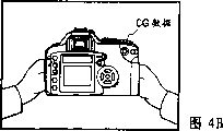
Fig. 4 A to 4D is the figure that represents to extract according to the hand region of first embodiment example of handling respectively;
Fig. 5 is the figure of expression according to the treatment scheme of first embodiment;
Fig. 6 is the figure that expression is attached to the mark example of simple prototype;
Fig. 7 A and 7B are the figure of example that represents to be used for the method for expressive notation respectively;
Fig. 8 is the figure of example of the method for the expression positional information that is used to calculate mark;
Fig. 9 is the block diagram of expression according to the structure of the message handler of second embodiment;
Figure 10 is the figure of expression according to the treatment scheme of second embodiment;
Figure 11 is the figure of expression according to the treatment scheme of the 3rd embodiment;
Figure 12 is the block diagram of expression according to the structure of the message handler of the 4th embodiment;
Figure 13 is the figure of expression according to the treatment scheme of the 4th embodiment; And
Figure 14 is that example illustrates with respect to unique point, the figure of correction position/direction tolerance.
Embodiment
Below with reference to the accompanying drawings, the preferred embodiments of the present invention are described.
To describe below, in the mixed reality system according to this embodiment, by using same position and directional information, show three-dimensional CG (3D-CG) data of conversion three-dimensional CAD data generation from the simple prototype (simple entity model) of three-dimensional CAD data creation by the rapid prototyping producing device.Therefore, can realize visual evaluation and sense of touch evaluation simultaneously so that can estimate the three-dimensional CAD data with more perfect form.In addition, the processing of the simple prototype that produces in the three-dimensional data that is used for being created by 3D-CAD for being easy to prepare overlapping processing, can be handled CF of simple prototype or the like.
[first embodiment]
Mixed reality system according to first embodiment will be described below.The simple prototype (simple entity model) that the setting of mixed reality system is created based on the three-dimensional data of being created by 3D-CAD, and being used for of showing on this simple prototype is convenient to extract the color corresponding to the background of the part of operator's hand on the 3D-CG data.
Fig. 1 represents the system architecture according to first embodiment.
Fig. 1 comprises and will be worn over observer's head, is used to observe the wear-type image input/output apparatus (abbreviating the head-mounted display of HMD as) of the image that is produced by the synthetic of real space and virtual space image.Fig. 1 further comprises magnetic transmitter (magnetic transmitter) 200, magnetic sensor 201 and 202, position/orientation measurement mechanism 205, simple prototype (simple entity model) 300 and pedestal 301.Magnetic transmitter 200 produces magnetic field.Magnetic sensor 201 and 202 is used for measuring the variation in the magnetic field that is produced by magnetic transmitter 200.Position/orientation measurement mechanism 205 is measured the position and the direction of magnetic sensor 201 and 202 based on the measurement result of magnetic sensor 201 and 202.Magnetic sensor 201 is connected to position and the observer's direction of observation that HMD100 went up and be used for calculating observer's viewpoint.Simple prototype (simple entity model) is served as the operating unit that holds and operate by the observer.The same with HMD100, magnetic sensor 202 is included in the simple prototype 300.Position/orientation measurement mechanism 205 calculates the position and the direction of simple prototype 300 based on the measurement result from magnetic sensor 202.Pedestal 301 is used to observe simple prototype 300.
Fig. 1 further comprises image display device 101, image-input device 102 and message handler 400.Image display device 101 is included among the HMD100.The a pair of image-input device 102 that is used for right and left eyes is included in HMD100.Message handler 400 is according to the position/orientation information of being calculated by position/orientation measurement mechanism 205, create the CG image, the CG image is placed on the image of being imported by the image-input device 102 of HMD100, and the image that will finally synthesize outputs on the image display device 101 of HMD100.
Then, the more specifically structure of HMD100 will be described with reference to Figure 2.Fig. 2 comprises image display device also shown in Figure 1 101 and free face prism (free form surfaceprism) (being called the FFS prism hereinafter) 103.Image display device comprises about 0.5 to several inches little liquid crystal displays.FFS prism 103 is as the lens that are used for the image on the enlarged image display device 101.Under this structure, for example the image that shows can be provided as 90 inches images on image display device 101 in the preceding 2 meters distances of observer.
Fig. 2 further comprises image-input device also shown in Figure 1 102 and image capturing system prism 104.Image-input device 102 comprises image capture apparatus, such as CCD camera and CMOS camera.Image capturing system prism 104 serves as and is used for the optical convergence of the real space lens in the image-input device 102.It is outer so that the optical axis of two prisms can be identical that image capturing system prism 104 is positioned at FFS prism 103.Therefore, can eliminate image and the parallax between the image that shows on the image display device 101 by image-input device 102 input, and the image of reconstruct real space normally.
Then, the concrete structure of message handler 400 among Fig. 1 will be described with reference to figure 3.
Image compound component 402 is placed on (writing) by virtual space image (CG image) and creates composograph on the real space view data.In this case, owing to will write the CG image on the actual real-world object of placing before the CG image, between CG image and real-world object depth offset may appear.
Fig. 4 A represents by the example of the real space view data of image-input device 102 input and is image by observer's the simple prototype that holds.Before simple prototype, have the part (thumb part) of hand.Fig. 4 B is a composograph, wherein will be placed on corresponding to the CG image of simple prototype on the image among Fig. 4 A.In other words, being covered by the CG image should be at the part hand before the simple prototype, and depth offset occurs.Thus, the observer can feel that some things are wrong in image.
Mixed reality system according to first embodiment can use the real space view data of preserving in message handler 400, by Flame Image Process, overcome aforesaid depth offset.In other words, by carries out image processing, only the view data (Fig. 4 A) from image-input device 102 inputs extracts hand region.Create masked images (Fig. 4 C, and create the CG image that is used in the no hand region of masked images appointment by the hand region that extracted.The CG image is placed on the real space image.Thus, can before simple prototype, show hand region, and can eliminate the sensation that degree of depth aspect goes wrong.
According to this embodiment, when the operator grasps simple prototype 300, use color, give simple prototype 300 painted such as blueness, the tone of its tone and hand color differs widely, so that can be from the real space image information with the part of high reliability extraction corresponding to hand.The real space image information also comprises the real object (such as the pedestal 301 of placing simple prototype 300 and screen on every side) of the background of simple prototype 300 and observer's hand and simple prototype 300.According to this embodiment, in order to extract part with high reliability, give the real-world object of background of simple prototype 300 painted with color corresponding to hand from the real space image information, the tone of its tone and hand color differs widely.For example, can be painted to real-world object with green, or can cover green-fabrics or paper thereon.
In addition, when the simple prototype 300 in the background and real-world object have substantially the same color (such as indigo plant), can easier establishment hand colouring information record data 421.In this case, hand colouring information record data 421 are used for extracting part corresponding to observer's hand from the real space image information as numerical data input.In other words, when simple prototype 300 and background have different colours, consider the color region that has in the color space, the hand color region that must record will extract.On the other hand, when simple prototype 300 and background have substantially the same color, consider the zone that has color in the color space, can only write down the hand color region that will extract.Will be further described below this point.Owing to write down color by the zone in the bulletin colour space, the hand color region that extracts slightly decided according to background color.In other words, when background color and hand color have significantly different tones, can define the hand color region that to extract roughly.On the other hand, when background color and hand color have close tone, must define the hand color region that will extract more accurately.Otherwise it is the hand color that background color (or its part) is extracted.Therefore, when background does not have substantially the same color with simple prototype, must define the hand color region that will extract more accurately than the situation that background and simple prototype have substantially the same color.
When simple prototype and background had substantially the same color (such as indigo plant), the boundary line (profile) between the real-world object of simple prototype and background became visually unclear.Therefore, even when with respect to simple prototype, during mobile a little CG data, this moves visually is unconspicuous.
To describe according to the treatment scheme in the message handler with said structure 400 of this embodiment with reference to figure 5.At first, will step that be reproduced data 406 by simple prototype 300 of 3D-CAD data creation and 3D-CG be described with reference to the treatment step on the left-hand side of figure 5.
For by using general 3D-CAD system design form or creation design (step 1010), usually design data is stored as employed 3D-CAD system intrinsic stereo data.By using for example rapid prototyping producing device, create simple prototype 300 (step 1110) by stereo data.On the other hand, the 3D stereo data is represented by the one group of geometric parameter that is used for design part and can not be reproduced in the CG former state.Therefore, the 3D stereo data is converted to the data layout (such as VRML) (step 1210) that is suitable for reproducing 3D-CG.In mixed reality system, create the Virtual Space by using the 3D-CG that produces by this conversion to reproduce data 406 according to this embodiment.
Then, will treatment step according to the mixed reality system of this embodiment be described with reference to the dexter treatment step of figure 5.
At first, the step (not shown) before step 2010 is measured the initial position and the direction of simple prototype 300.For example, fix in the precalculated position with the fixing simple prototype 300 of predetermined direction, and read the position of magnetic sensor 202 this moment and the measured value of direction.Then, the difference between measured value and the predetermined value is treated to " sensor link position and direction ".Position/orientation measurement mechanism 205 uses data and the initial position of magnetic transmitter 200 and magnetic sensor 202 and true spatial location and the direction (step 2010) that direction is measured simple prototype 300.Similarly, position/orientation measurement mechanism 205 uses the data measurement of magnetic transmitters 200 and magnetic sensor 201 to be installed in position and the direction (step 2020) of the HMD100 on the observer in the real space.By position/orientation message input device 404, will capture in the message handler by the measurement data that position/orientation measurement mechanism 205 provides.Then, position/orientation calculating unit 405 calculates the relative position/direction relations (step 2030) of 300 of HMD100 and simple prototypes.
On the other hand, with step 2010,2020 and 2030 parallel, by image capture parts 400, will be in message handler 400 from the real space image capture of the image-input device 101 of HMD device 100.
In step 3010, the image capture parts 401 of message handler 400 are captured the real space view data.Then, hand region extracting said elements 420 compares the color of pixel information and the colouring information of the hand region by hand colouring information record data 421 record in advance.If color of pixel information is consistent with the colouring information of hand region, pixel color is judged the color of the hand that is the people.Therefore, pixel is judged as hand region (step 5010).Then, on all pixels, carry out the judgement that is used to belong to hand region.Only extract and be judged as the pixel that belongs to hand region, and only the data of hand region are recorded in storer, in video buffer.Therefore, create masked images (step 5020).
On the other hand, will also be stored in storer in the real space view data that step 3010 is captured, such as (step 3020) in the video buffer.Image compound component 402L and 402R will be placed at the CG image that step 2040 is created on the view data of step 3020 storage (step 4010).For example, convert composograph to analog video signal by image creation parts 403 and on the image display device 101 of HMD100, show (step 4020).Because composograph does not comprise the CG image in the hand region parts of masked images, the image that can obtain to have the natural degree of depth shown in Fig. 4 D.
During the image update cycle in image display device 101, or during the update cycle of the step 2040 that CG reproduces, repeating step 2010 to 4020 is so that can provide information in real time.According to the example of the result of this embodiment shown in Fig. 4 A to 4D.
Although according to first embodiment, magnetic devices the invention is not restricted to this with the unit that acts on measuring position and direction.Obviously, can use another unit such as optical position/orientation measurement device.
As mentioned above, according to first embodiment, have on the simple prototype of creating by identical three-dimensional data, on the display of the 3D-CG data that the three-dimensional data of being created by 3D-CAD is created, will be different from the color (such as complementary colors) of simple prototype 300 and background object from the color (such as the color of hand region) of the presumptive area of image contract.Best, the color of simple prototype 300 and background object is substantially the same.Therefore, can realize region extraction easier and safely.In other words, can easier execution be used for the 3D-CG data are placed on preparation (comprising record hand colouring information record data) on the simple prototype 300.
[second embodiment]
According to first embodiment, for example, magnetic executing location/orientation measurement.Yet in magnetic position/orientation measurement, some environment may cause the instability of the precision that is used to measure.When near the magnetic transmitter, having metal object, for example, the magnetic field disturbance that can become, this can cause magnetic sensor to export unstable definite value.In addition, when the distance between magnetic transmitter and magnetic sensor increased, measuring accuracy can reduce, and this is a problem.Not only produce the problem of measuring accuracy at magnetic sensor but also in various measurement mechanisms.
Therefore, based on the real space view data in the message handler 400, correction position and direction are so that improve measuring accuracy according to the mixed reality system of second embodiment.For example, as shown in Figure 6, the mark (marker) that will be used for image recognition is attached on simple prototype 300 and as unique point.Can use various marks, such as the shape mark 310 and the color mark 311 of opsition dependent/direction algorithm.In addition, according to second embodiment, mark is provided and uses the reference that acts on link position/correction for direction mark to simple prototype 300.Therefore, can obtain to be used for the positional information of accompanying mark easily.
The method of passing through usage flag (hereinafter, being called unique point) correction position and direction will be described here.Here, will be used for being described as general bearing calibration by the method that a unique point correction is used for the external parameter of image input block (camera).Here, unique point can be the mark of the pressure sensitive adhesive stationery on the simple prototype that is placed in the real space.In this case, pressure sensitive adhesive stationery mark has relevant artificial information of specifying CF.In addition, unique point can be the feature with simple prototype form.
Figure 14 represents to be used for the synoptic diagram of general bearing calibration of the external parameter (parameter of expression position and direction) of image-input device (camera).In Figure 14, some A is meant that some B is meant the physical location of unique point, and puts the position that C is meant the viewpoint of image-input device (camera) based on the position of the desired unique point of the position of image-input device (camera) and simple prototype 300 and direction.In this case, the position of representing with some A and B is the position in the camera coordinate system, and some C is the initial point of the coordinate system of image-input device (camera).Point P is meant the position of some A on the plane of delineation, and some Q is meant the position of some B on the plane of delineation.Here, as shown in figure 14, (x
p, y
p) and (x
q, y
q) be respectively the coordinate of a P and Q, w and h are respectively the width and the height of the plane of delineation, and d is camera focal length (distance from the plane of delineation to the image-input device).In addition, v
1Be vector from a C to a Q, v
2Be vector, and θ is v from a C to a P
1And v
2Between angle.
At first, will describe, change from a B direction to the method for the direction θ of A direction (that is, by using the bearing calibration of image rotating input media) by using a unique point.
By calculating v by these setting values
1And v
2, divide vector to be expressed as:
[EQ1]
Then, vector is standardized as vector by following equation with value 1:
[EQ2]
Here, when image rotating input media (camera), turning axle is perpendicular to having vector v
1And v
2The plane, and be the straight line of position (some C) by the viewpoint of camera.By following equation, can be by vector v
1And v
2The vector product direction vector that calculates turning axle (be actually a standardized vector (v
1', v
2'):
[EQ3]
v
x=v
1′×v
2′…(3)
Here, v
xThey be the direction vector of turning axle, and (l, m n) are meant its component.Rotation angle θ is by vector v
1And v
2The angle that forms and can calculating by following equation:
[EQ4]
θ=arccos(v
1′·v
2′)…(4)
Therefore, can pass through following equation, calculating will be used for the correction matrix Δ M by the correction of image rotating input media
c
[EQ5]
By correction matrix being multiply by the position of presentation video input media and the matrix of direction, position and direction that can the correcting image input media.In other words, at the position of Q display dot P, and consistent by the desired mark position of position on the plane of delineation and direction with true mark position.Although described the bearing calibration of use image rotating input media (camera) above, also can use the parallel motion that is used for by image-input device, the method for correction error.Even by using the bearing calibration of a plurality of unique points, also can obtain identical effect, but the descriptions thereof are omitted this general.
The mark that accords with that is used to mark can be one group of cross linear (Fig. 7 A) or comprise one group of verification model (Fig. 7 B) of representing the point of intersection point.The angle that forms by cross linear is not limited to 90 degree, but can be any angle, such as 60 degree.When the position that accurately is intended for marking, can only provide mark to this point.
Provide mark by model reproduction, model protrusion or protrusion and following formation.When object comprises markup model or shape in advance, do not need another mark.
By using laser surveying instrument, measure the positional information of assigned tags.When in the testing model in the plane fitly during registration mark (mark), shown in Fig. 7 A and 7B, need to measure the positional information of the mark at three some places point-blank here.Therefore, can calculate the positional information of whole mark easily.For example, in Fig. 8, when the positional information of mark A, B and C is X
A=(X
A, Y
A, Z
A), X
B=(X
B, Y
B, Z
B) and X
C=(X
C, Y
C, Z
C) time, by following equation, can calculate the positional information of mark D:
X
D=X
A+3×(X
B-X
A)+4×(X
C-X
A)[A]
As mentioned above, give the mark that fixes on known position, and based on this mark, labelling.Therefore, can carry out described correction, and following advantage can be provided with reference to Figure 14:
(1) even when sticking a plurality of sign, " only needing to measure the mark at three some places ".Therefore, can reduce the measurement number of times; And
(2) when marking again, be easy to position by the mark calculation flag.Thus, needn't carry out measurement (this is an advantage, because use the measurement of laser surveying instrument to need time and work) again.
Term " position of mark " and " position of sign " are meant the sign in the coordinate system that limits and the position of mark in simple prototype 300.
Then, will be with reference to figure 9 and 10 structure and the treatment schemees of describing according to the mixed reality system of second embodiment.For identical reference number is specified in same parts and processing (Fig. 5) according to this structure (Fig. 3) of first embodiment, and will omit detailed description.
Marker detection parts 410 are by being sent to position/orientation calculating unit 405 by the mark shown in image detection Fig. 6 of image capture parts 40L and 401R input and with testing result (such as the position of mark).Position/orientation calculating unit 405 is created control information based on from the testing result of marker detection parts 410 and the mark position that detects based on the position/orientation information from 404 inputs of position/orientation information input part.By using control information, proofread and correct and export position and direction based on the simple prototype 300 of the position/orientation information calculations of importing by position/orientation information input part 404.
To simple prototype 300 specified signs of creating from the 3D stereo data by the rapid prototyping producing device (step 1111).Then, by laser surveying instrument, the position of survey mark, and write down final mark position information (step 1112).Then, with reference to specified sign, mark (step 1120).In addition, the witness marker positional information is calculated the information and the record (step 1130) of relevant position of marking.For example, mark is attached to the position of given sign as shown in Figure 8,, calculates mark position by above-mentioned [A].
In the processing of mixed reality system,, the real space view data is trapped in the message handler 400 in step 3010.Then, marker detection parts 410 extract the position that is attached to the mark on simple prototype 300 from the real space view data.By using the mark position of store in advance and in the position of step 3011 from the view data extraction in step 1130, calculation correction information, and pass through the control information calculated, proofread and correct from 205 outputs of position/orientation measurement mechanism and capture measurement result (step 2031) the message handler 400.Then, by using correction data, carry out CG and reproduce (2040).
Although according to this embodiment, stick and give the sign mark of correlation of simple prototype 300, the invention is not restricted to this.Can stick with the background that gives simple prototype 300 in the relevant mark of sign of real-world object (such as pedestal).Simple prototype in background and real-world object specified sign.
As mentioned above, according to second embodiment, can to simple prototype provide the sign and with acting on the reference of marking.Therefore, can obtain the positional information of the mark that pasted.In other words, can carry out easily for the preparation (record mark positional information) that the processing of 3D-CG data is set on simple prototype.
[the 3rd embodiment]
According to the 3rd embodiment,, provide mark to simple prototype (simple entity model) according to second embodiment by providing the character shape data to the 3D-CAD of simple prototype data.To treatment scheme according to the 3rd embodiment be described with reference to Figure 11.With represented by identical reference number according to the identical step of the processing (Figure 10) of second embodiment.Structure according to the mixing physical system of the 3rd embodiment is identical with the structure (Fig. 9) of second embodiment.
At first, use three dimensional CAD system 1010 to provide character shape data (step 1011) and record position information (step 1012) thereon to the 3D-CAD stereo data.In other words, provide the shape data of sign to the 3D-CAD stereo data as the 3D-CAD stereo data.Here, the character shape data can comprise a plurality of apertures or the projection (seeing Fig. 7 A and 7B) of a plurality of cross aisles or expression intersection point.In this case, the angle that is formed by cross aisle is not limited to 90 degree, but can be any angle, such as 60 degree.Obviously, when the position accurately determining to mark, can only provide shape data, such as aperture and projection to the position.Here, only by the assigned tags position, can be in 3D-CAD system 1010 the built-in mechanism that is used for providing the shape data that pre-creates from the trend precalculated position.
Then, in step 1110, create in the processing in the 3D molding, the rapid prototyping producing device that is used for for example light molding is created the simple prototype 300 with character shape.In other words, on the surface of simple prototype 300, provide little passage or aperture or projection.For example, establishment has the simple prototype of the sign shown in Fig. 7 A or 7B.With reference to the specified sign shape, mark is attached on the simple prototype 300 (step 1120).
Based on the relevant positional information (at step 1012 record) that gives the character shape data of 3D-CAD stereo data, calculate relevant positional information and the record (step 1130) that is attached to the mark of simple prototype 300.Can in 3D-CAD system 1010, calculate easily appointment " positional information of relevant shape data).For example, can by from the distance of the absolute distance of nearest character shape and/or a plurality of character shape in background than, be easy to calculate the positional information of associated mark.
On the other hand, owing to do not need to be assigned to the sign that 3D-CG reproduces data, will there be the 3D-CAD stereo data of character shape data to convert the data layout (such as VRML) (step 1210) that is suitable for reproducing 3D-CG to.For example, the shape data to the 3D-CG that is not assigned to the 3D-CAD solid data reproduces data defines " no return " sign.Reproduce in the data-switching step 1210 at 3D-CG, only will not have the shape data of " no return " sign to convert the 3D-CG data to.
According to the 3rd embodiment, the character shape data are given the 3D-CAD data of naive model and use and act on the reference of marking.Yet, the invention is not restricted to this.In the background of simple prototype, the character shape data can be assigned to real-world object 3D-CAD data (such as pedestal) and can be with acting on the reference of marking.Can be to the 3D-CAD of the real-world object in simple prototype and background data specified sign shape data.
Although according to the 3rd embodiment, the character shape data are assigned to the 3D-CAD data, can automatically provide the mechanism of reservation shape data to be built in the 3D-CAD system 1010 with being used for only passing through the mark position of the relevant 3D-CAD data of appointment.For example, response provides the instruction of character shape data, can provide the sign with chequer shown in Fig. 7 A in the following left comer that is predefined for desired location.
As mentioned above, by the character shape data being provided to the 3D-CAD of simple prototype data and character shape data usefulness being acted on the reference of marking,, can obtain the positional information of relevant institute labelling easily according to the 3rd embodiment.In other words, can be easy to carry out the preparation (record mark positional information) that is used for processing overlapping placement prototype and 3D-CG data.
[the 4th embodiment]
The 4th embodiment is the mixed reality system, wherein by specifying the sensor embedded location in the 3D-CAD data, creates sensor and embed shape in simple prototype (simple entity model).
Figure 12 represents the concrete structure according to the message handler 400 of the 4th embodiment.Structure identical with first embodiment (Fig. 3) according to the message handler 400 of the 4th embodiment.Yet,, omit with hand region at this and extract relevant element (being hand region extracting said elements 420 and hand colouring information record data 421) owing to, do not extract hand region according to this embodiment.Obviously, can carry out as the hand region in first embodiment extract and/or as in a second embodiment mark extract.
Then, will treatment scheme according to the 4th embodiment be described with reference to Figure 13.To with specify identical mark according to the identical step of the processing (Fig. 5) of first embodiment.
At first, sensor embedded location and the direction of using three dimensional CAD system 1010 to specify in the 3D-CAD stereo data.As the sensor embedded location, for example, center that can specified sensor.In other words, embed shape data (step 1013) to 3D-CAD stereo data specified sensor, and write down its positional information and directional information (step 1014).Thus, sensor being embedded shape data is assigned in the 3D-CAD stereo data.For example, be used for providing the mechanism that pre-creates sensor embedding shape data can be built in 3D-CAD system 1010 automatically at assigned position with prescribed direction.Then, for example, the rapid prototyping producing device is created has the simple prototype 300 (step 1110) that sensor embeds shape.
On the other hand, do not provide sensor to embed shape owing to do not need to reproduce data to 3D-CG, reproduce data-switching step 1210 at 3D-CG, the 3D-CAD stereo data that will not have sensor to embed shape data converts the data layout (such as VRML) that is suitable for reproducing 3D-CG to.Thus, " no return " that be used for the sensor embedding shape of 3D-CAD stereo data by for example definition indicates and avoids reproducing the conversion of data-switching step 1210 at 3D-CG to have the data of " no return " sign, and creating does not have the 3D-CG of sensor reproduction shape to reproduce data 406.
The mixed reality system produces the Virtual Space by using the 3D-CG that is produced by conversion to reproduce data 406.In other words, use position and the direction (step 2001) that writes down simple prototype 300 in the sensing station information of step 1014 record.Then, use about institute's initial position that writes down of transmitter 200 and sensor 202 and directional data and measure in the real space the simply position and the direction (step 2010) of prototype 300.According to first to the 3rd embodiment, the step before step 2010 is measured the initial position and the direction of simple prototype 300.For example, can fix simple prototype 300 in the precalculated position with predetermined direction, and the position and the direction measurement that read the sensor of this moment.Difference between measured value and predetermined value is treated to " position of the sensor of being installed and direction ".
As mentioned above,, embed shape, can in simple prototype, create sensor easily and embed shape by specifying the sensor on the 3D-CAD data according to the 4th embodiment.In other words,, can carry out the preparation that is used for simple prototype of overlapping placement and 3D-CG data (create sensor and embed shape) easily, therefore create sensor and embed shape owing to can embed shape than creating the easier establishment sensor of simple prototype.
As mentioned above, according to the foregoing description, be easy to carry out and be used to use the preparation of mixed reality system so that carry out by using same position and directional information, to be placed in the rapid prototyping device by the 3D-CG data of conversion 3D-CAD data creation, by the processing on the simple prototype (simple entity model) of identical 3D-CAD data generation.
Even, obviously can realize purpose of the present invention by storage being used for realize that storage medium according to the program code of the software of the function of the foregoing description is provided to system or device and reads and carry out the program code that is stored in this storage medium by the computing machine (or CPU or MPU) of system or device.
In this case, the program code that reads from storage medium is realized the function according to the foregoing description, and the present invention includes program code stored storage medium.
Being used to the storage medium of program code is provided can be floppy disk, hard disk, CD, magneto-optic disk, CD-ROM, CD-R, tape, Nonvolatile memory card or ROM.
Obviously, according to the present invention, the program code that the computing machine execution is read is so that can realize the function of the foregoing description.In addition, according to the present invention, for example on computers the operating system (OS) of operation based on instruction from program code, can operating part or all actual treatment so that this processing can realize the function according to the foregoing description.
In addition, according to the present invention, to write the expansion board the computing machine from the program code that storage medium reads or be connected to computing machine, CPU, for example in the storer in the functional expansion unit in the expansion board, or functional expansion unit is based on the instruction from program code, operating part or all after the actual treatment so that handle this function that can realize according to the foregoing description.
Although described the present invention with reference to the current most preferred embodiment of thinking, it will be appreciated that to the invention is not restricted to the disclosed embodiments.On the contrary, the invention is intended to cover interior various improvement and the equivalent of spirit and scope that is included in accessory claim.The scope of following claims should meet the most widely to be explained so that comprise all these improvement and equivalent structure and function.
Claims (12)
1. one kind is used for to specify viewpoint to provide by the image of virtual space image and real space being merged the method for displaying image of the composograph that generates to the observer, and described method comprises:
A) input step is used to import the real space image, and described real space image is comprised based on the real space of the solid model of three-dimensional CAD data creation by image capture apparatus picked-up captures;
B) measuring process is used to measure the position and the direction of described image capture apparatus and described solid model and obtains the described position of solid model described in the described real space image of expression and the position/orientation information of direction;
C) region extraction step is used for extracting the zone that comprises predetermined color from described real space image; And
D) synthesis step, be used for by not having under the situation in the described zone that described region extraction step extracts, in described real space image, based on described position/orientation information and described three-dimensional CAD data, on described solid model, reproduce the three dimensional computer graphics image, described real space image and described three dimensional computer graphics image are merged
It is characterized in that described solid model has the different color of color with the described zone that will extract in described region extraction step.
2. method for displaying image as claimed in claim 1 is characterized in that, described solid model has the complementary colors of the color in the zone that will extract in described region extraction step.
3. method for displaying image as claimed in claim 1 is characterized in that, the color of described solid model is identical with the color of real-world object in the background that will be included in described real space image basically.
4. method for displaying image as claimed in claim 1 is characterized in that, the color of the real-world object in the background that is included in the described real space image is different from the color of described solid model.
5. one kind is used for to specify viewpoint to provide by the image of virtual space image and real space being merged the method for displaying image of the composograph that generates to the observer, and described method comprises:
A) input step is used to import the real space image, and described real space image is comprised based on the real space of the solid model of three-dimensional CAD data creation by image capture apparatus picked-up captures;
B) feature point extraction step is used for extracting mark from described real space image, and described mark is positioned at the known three-dimensional position place on the described solid model;
C) measuring process, be used to measure the position and the direction of described image capture apparatus and described solid model, obtain the described position of the described solid model in the described real space image of expression and the position/orientation information of direction, and, proofread and correct described position/orientation information based on the position of the described mark that in described feature point extraction step, extracts; And
D) synthesis step, be used for by based on described position/orientation information of proofreading and correct and described three-dimensional CAD data at described measuring process, reproduce the three dimensional computer graphics image on the described solid model in the described real space image that in described input step, obtains, described real space image and described three dimensional computer graphics image are merged
It is characterized in that the described three-dimensional position of the described mark on the described solid model is the position about the sign on the described solid model.
6. method for displaying image as claimed in claim 5 further comprises the measuring process of the described position that is used to measure the described sign on the described solid model.
7. method for displaying image as claimed in claim 5 further comprises:
Foundation step is used for the three-dimensional CAD data based on the position/shape data that comprise described sign, creates described solid model so that create the described solid model that has described sign thereon,
It is characterized in that described synthesis step reproduces described three dimensional computer graphics image, and based on described position/shape data, obtains the described position of described sign based on the described three-dimensional CAD data of the described position/shape data of getting rid of described sign.
8. method for displaying image as claimed in claim 7 is characterized in that, is used to create the position that indicates described in the three dimensional CAD system of described three-dimensional CAD data by appointment, provides described position/shape data.
9. one kind is used for to specify viewpoint to provide by the image of virtual space image and real space being merged the method for displaying image of the composograph that generates to the observer, and described method comprises:
A) foundation step is used for based on the three-dimensional CAD data with shape data, creates the solid model with attachment members, and described shape data is used to form described attachment members;
B) input step is used to import the real space image, and described real space image comprises that by image capture apparatus picked-up the real space of described solid model captures;
C) measuring process is used to measure the position and the direction of described image capture apparatus and described solid model and obtains the described position of solid model described in the described real space image of expression and the position/orientation information of direction; And
D) synthesis step, be used for by described three-dimensional CAD data based on described position/orientation information and the described shape data of eliminating, reproduce the three dimensional computer graphics image on the described solid model in described real space image, described real space image and described three dimensional computer graphics image are merged.
10. one kind is used for to specify viewpoint to provide by the image of virtual space image and real space being merged the image display system of the composograph that generates to the observer, and described system comprises:
A) input block is used to import the real space image, and described real space image is comprised based on the real space of the solid model of three-dimensional CAD data creation by image capture apparatus picked-up captures;
B) measuring unit is used to measure the position and the direction of described image capture apparatus and described solid model and obtains the described position of solid model described in the captured image of expression and the position/orientation information of direction;
C) region extraction unit is used for extracting the zone that comprises predetermined color from described real space image; And
D) synthesis unit, be used for by under the situation in the described zone of not extracting by described region extraction unit, in described real space image, based on described position/orientation information and described three-dimensional CAD data, on described solid model, reproduce the three dimensional computer graphics image, described real space image and described three dimensional computer graphics image are merged
It is characterized in that described solid model has the different color of color with the described zone that will be extracted by described region extraction unit.
11. one kind is used for to specify viewpoint to provide by the image of virtual space image and real space being merged the image display system of the composograph that generates to the observer, described system comprises:
A) input block is used to import the real space image, and described real space image is comprised based on the real space of the solid model of three-dimensional CAD data creation by image capture apparatus picked-up captures;
B) feature point extraction unit is used for extracting mark from described real space image, and described mark is positioned at the known three-dimensional position place on the described solid model;
C) measuring unit, be used to measure the position and the direction of described image capture apparatus and described solid model, obtain the described position of the described solid model in the described real space image of expression and the position/orientation information of direction, and, proofread and correct described position/orientation information based on the position of the described mark that extracts by described feature point extraction unit; And
D) synthesis unit, be used for by based on described position/orientation information and described three-dimensional CAD data, on by the described solid model in the described real space image of described image capture apparatus picked-up, reproduce the three dimensional computer graphics image, captured image and described three dimensional computer graphics image are merged
It is characterized in that the three-dimensional position of the described mark on the described solid model is the position about the sign on the described solid model.
12. one kind is used for to specify viewpoint to provide by the image of virtual space image and real space being merged the image display system of the composograph that generates to the observer, described system comprises:
A) creating unit is used for based on the three-dimensional CAD data with shape data, creates the solid model with attachment members, and described shape data is used to form described attachment members;
B) input block is used to import the real space image, and described real space image comprises that by image capture apparatus picked-up the real space image information of described solid model captures;
C) measuring unit is used to measure the position of described image capture apparatus and described solid model and direction and acquisition and is illustrated in the described position of solid model described in the described real space image and the position/orientation information of direction; And
D) synthesis unit, be used for by described three-dimensional CAD data based on described position/orientation information and the described shape data of eliminating, reproduce the three dimensional computer graphics image on the described solid model in described real space image, described real space image and described three dimensional computer graphics image are merged.
Applications Claiming Priority (2)
| Application Number | Priority Date | Filing Date | Title |
|---|---|---|---|
| JP341627/2003 | 2003-09-30 | ||
| JP2003341627A JP3991020B2 (en) | 2003-09-30 | 2003-09-30 | Image display method and image display system |
Publications (2)
| Publication Number | Publication Date |
|---|---|
| CN1604026A CN1604026A (en) | 2005-04-06 |
| CN1304930C true CN1304930C (en) | 2007-03-14 |
Family
ID=34309071
Family Applications (1)
| Application Number | Title | Priority Date | Filing Date |
|---|---|---|---|
| CNB200410080657XA Expired - Fee Related CN1304930C (en) | 2003-09-30 | 2004-09-29 | Image display method and image display system |
Country Status (5)
| Country | Link |
|---|---|
| US (1) | US7397481B2 (en) |
| EP (1) | EP1521215B1 (en) |
| JP (1) | JP3991020B2 (en) |
| CN (1) | CN1304930C (en) |
| DE (1) | DE602004008001T2 (en) |
Families Citing this family (33)
| Publication number | Priority date | Publication date | Assignee | Title |
|---|---|---|---|---|
| KR100503789B1 (en) * | 2002-03-11 | 2005-07-26 | 삼성전자주식회사 | A rendering system, rendering method, and recording medium therefor |
| JP4227561B2 (en) * | 2004-06-03 | 2009-02-18 | キヤノン株式会社 | Image processing method and image processing apparatus |
| JP4667111B2 (en) * | 2005-04-21 | 2011-04-06 | キヤノン株式会社 | Image processing apparatus and image processing method |
| CN100590660C (en) * | 2005-07-15 | 2010-02-17 | 佳能株式会社 | Image processing device and method for design |
| JP4914123B2 (en) | 2005-07-15 | 2012-04-11 | キヤノン株式会社 | Image processing apparatus and method |
| US8264477B2 (en) * | 2005-08-05 | 2012-09-11 | Pioneer Corporation | Image display apparatus |
| JP4795091B2 (en) * | 2006-04-21 | 2011-10-19 | キヤノン株式会社 | Information processing method and apparatus |
| FR2901049B1 (en) * | 2006-05-12 | 2008-11-21 | Techviz Soc Par Actions Simpli | ENCODING METHOD AND DISPLAY SYSTEM ON A SCREEN OF A DIGITAL MODEL OF AN OBJECT IN THE FORM OF A SYNTHESIS IMAGE |
| JP4764305B2 (en) * | 2006-10-02 | 2011-08-31 | 株式会社東芝 | Stereoscopic image generating apparatus, method and program |
| DE102007045834B4 (en) * | 2007-09-25 | 2012-01-26 | Metaio Gmbh | Method and device for displaying a virtual object in a real environment |
| JP4950834B2 (en) * | 2007-10-19 | 2012-06-13 | キヤノン株式会社 | Image processing apparatus and image processing method |
| JP5403974B2 (en) * | 2008-09-09 | 2014-01-29 | キヤノン株式会社 | 3D CAD system |
| JP2010121999A (en) * | 2008-11-18 | 2010-06-03 | Omron Corp | Creation method of three-dimensional model, and object recognition device |
| WO2010064148A1 (en) * | 2008-12-03 | 2010-06-10 | Xuan Jiang | Displaying objects with certain visual effects |
| US8436893B2 (en) * | 2009-07-31 | 2013-05-07 | 3Dmedia Corporation | Methods, systems, and computer-readable storage media for selecting image capture positions to generate three-dimensional (3D) images |
| US8508580B2 (en) * | 2009-07-31 | 2013-08-13 | 3Dmedia Corporation | Methods, systems, and computer-readable storage media for creating three-dimensional (3D) images of a scene |
| US9380292B2 (en) | 2009-07-31 | 2016-06-28 | 3Dmedia Corporation | Methods, systems, and computer-readable storage media for generating three-dimensional (3D) images of a scene |
| US8947455B2 (en) | 2010-02-22 | 2015-02-03 | Nike, Inc. | Augmented reality design system |
| US9185388B2 (en) | 2010-11-03 | 2015-11-10 | 3Dmedia Corporation | Methods, systems, and computer program products for creating three-dimensional video sequences |
| US10200671B2 (en) | 2010-12-27 | 2019-02-05 | 3Dmedia Corporation | Primary and auxiliary image capture devices for image processing and related methods |
| WO2012092246A2 (en) | 2010-12-27 | 2012-07-05 | 3Dmedia Corporation | Methods, systems, and computer-readable storage media for identifying a rough depth map in a scene and for determining a stereo-base distance for three-dimensional (3d) content creation |
| US8274552B2 (en) | 2010-12-27 | 2012-09-25 | 3Dmedia Corporation | Primary and auxiliary image capture devices for image processing and related methods |
| US8843350B2 (en) * | 2011-06-03 | 2014-09-23 | Walter P. Moore and Associates, Inc. | Facilities management system |
| GB2501924B (en) * | 2012-05-11 | 2015-06-24 | Sony Comp Entertainment Europe | System and method of book leaf tracking |
| JP5791082B2 (en) | 2012-07-30 | 2015-10-07 | 国立大学法人横浜国立大学 | Image composition apparatus, image composition system, image composition method and program |
| JP6138566B2 (en) * | 2013-04-24 | 2017-05-31 | 川崎重工業株式会社 | Component mounting work support system and component mounting method |
| DE102013207528A1 (en) * | 2013-04-25 | 2014-10-30 | Bayerische Motoren Werke Aktiengesellschaft | A method for interacting with an object displayed on a data goggle |
| GB201310373D0 (en) * | 2013-06-11 | 2013-07-24 | Sony Comp Entertainment Europe | Head-Mountable Apparatus and systems |
| JP6237326B2 (en) * | 2014-02-25 | 2017-11-29 | 富士通株式会社 | Posture estimation apparatus, posture estimation method, and computer program for posture estimation |
| JP6491068B2 (en) * | 2015-09-29 | 2019-03-27 | 富士フイルム株式会社 | Three-dimensional modeling system, information processing apparatus and method, and program |
| IT201700009585A1 (en) * | 2017-01-30 | 2018-07-30 | The Edge Company S R L | METHOD FOR RECOGNIZING OBJECTS FOR ENGINES OF REALITY INCREASED BY AN ELECTRONIC DEVICE |
| CN107918665B (en) * | 2017-11-23 | 2021-12-14 | 上海模袋网络科技有限公司 | System and method for rapid rendering of three-dimensional model and CAD information query |
| JP6746651B2 (en) * | 2018-09-26 | 2020-08-26 | 株式会社不動テトラ | Method of displaying composite image of ground improvement work |
Citations (2)
| Publication number | Priority date | Publication date | Assignee | Title |
|---|---|---|---|---|
| US5423554A (en) * | 1993-09-24 | 1995-06-13 | Metamedia Ventures, Inc. | Virtual reality game method and apparatus |
| EP0899690A2 (en) * | 1997-09-01 | 1999-03-03 | Mixed Reality Systems Laboratory Inc. | Apparatus and method for presenting mixed virtual reality shared among operators |
Family Cites Families (5)
| Publication number | Priority date | Publication date | Assignee | Title |
|---|---|---|---|---|
| JPH10320590A (en) * | 1997-05-19 | 1998-12-04 | Honda Motor Co Ltd | Composite image production device and method therefor |
| JP2002157606A (en) * | 2000-11-17 | 2002-05-31 | Canon Inc | Image display controller, composite reality presentation system, image display control method, and medium providing processing program |
| US7053915B1 (en) * | 2002-07-30 | 2006-05-30 | Advanced Interfaces, Inc | Method and system for enhancing virtual stage experience |
| JP4401727B2 (en) * | 2003-09-30 | 2010-01-20 | キヤノン株式会社 | Image display apparatus and method |
| JP2005108108A (en) * | 2003-10-01 | 2005-04-21 | Canon Inc | Operating device and method for three-dimensional cg and calibration device for position/attitude sensor |
-
2003
- 2003-09-30 JP JP2003341627A patent/JP3991020B2/en not_active Expired - Fee Related
-
2004
- 2004-09-28 DE DE602004008001T patent/DE602004008001T2/en active Active
- 2004-09-28 EP EP04255922A patent/EP1521215B1/en not_active Expired - Fee Related
- 2004-09-29 US US10/953,935 patent/US7397481B2/en active Active
- 2004-09-29 CN CNB200410080657XA patent/CN1304930C/en not_active Expired - Fee Related
Patent Citations (2)
| Publication number | Priority date | Publication date | Assignee | Title |
|---|---|---|---|---|
| US5423554A (en) * | 1993-09-24 | 1995-06-13 | Metamedia Ventures, Inc. | Virtual reality game method and apparatus |
| EP0899690A2 (en) * | 1997-09-01 | 1999-03-03 | Mixed Reality Systems Laboratory Inc. | Apparatus and method for presenting mixed virtual reality shared among operators |
Also Published As
| Publication number | Publication date |
|---|---|
| DE602004008001T2 (en) | 2008-04-30 |
| US20050068316A1 (en) | 2005-03-31 |
| DE602004008001D1 (en) | 2007-09-20 |
| CN1604026A (en) | 2005-04-06 |
| US7397481B2 (en) | 2008-07-08 |
| EP1521215B1 (en) | 2007-08-08 |
| EP1521215A1 (en) | 2005-04-06 |
| JP3991020B2 (en) | 2007-10-17 |
| JP2005107969A (en) | 2005-04-21 |
Similar Documents
| Publication | Publication Date | Title |
|---|---|---|
| CN1304930C (en) | Image display method and image display system | |
| CN1320423C (en) | Image display apparatus and method | |
| JP4958497B2 (en) | Position / orientation measuring apparatus, position / orientation measuring method, mixed reality presentation system, computer program, and storage medium | |
| US7529387B2 (en) | Placement information estimating method and information processing device | |
| JP4245963B2 (en) | Method and system for calibrating multiple cameras using a calibration object | |
| US4970666A (en) | Computerized video imaging system for creating a realistic depiction of a simulated object in an actual environment | |
| US8350897B2 (en) | Image processing method and image processing apparatus | |
| JP4926817B2 (en) | Index arrangement information measuring apparatus and method | |
| US10304206B2 (en) | Selecting feature patterns and corresponding layout positions for viewpoint measurement | |
| EP1596329A2 (en) | Marker placement information estimating method and information processing device | |
| US20050285879A1 (en) | Method and apparatus for processing information | |
| CN1905689A (en) | Information processing apparatus and method | |
| CN106683068A (en) | Three-dimensional digital image acquisition method and equipment thereof | |
| JP2006072903A (en) | Image compositing method and device | |
| CN1957373A (en) | Accuracy evaluation of video-based augmented reality enhanced surgical navigation systems | |
| JP2006285788A (en) | Mixed reality information generation device and method | |
| JP2006267879A (en) | Image processing method, image processing apparatus and marker | |
| JP4242529B2 (en) | Related information presentation device and related information presentation method | |
| JP2007064684A (en) | Marker arrangement assisting method and device therefor | |
| WO2020034738A1 (en) | Three-dimensional model processing method and apparatus, electronic device and readable storage medium | |
| JP2001243468A (en) | Device, method, and metdium for three-dimensional modeling, and device, method, and medium for three- dimensional shape data recording | |
| JP2005339127A (en) | Apparatus and method for displaying image information | |
| KR100549511B1 (en) | Method for producing picture drawing of gis using digital photogrammetry and laser scanning | |
| CN115235493A (en) | Method and device for automatic driving positioning based on vector map | |
| BARON et al. | APPLICATION OF AUGMENTED REALITY TOOLS TO THE DESIGN PREPARATION OF PRODUCTION. |
Legal Events
| Date | Code | Title | Description |
|---|---|---|---|
| C06 | Publication | ||
| PB01 | Publication | ||
| C10 | Entry into substantive examination | ||
| SE01 | Entry into force of request for substantive examination | ||
| C14 | Grant of patent or utility model | ||
| GR01 | Patent grant | ||
| CF01 | Termination of patent right due to non-payment of annual fee | ||
| CF01 | Termination of patent right due to non-payment of annual fee |
Granted publication date: 20070314 Termination date: 20210929 |