CN1301799C - Liquid spray head - Google Patents
Liquid spray head Download PDFInfo
- Publication number
- CN1301799C CN1301799C CNB031215920A CN03121592A CN1301799C CN 1301799 C CN1301799 C CN 1301799C CN B031215920 A CNB031215920 A CN B031215920A CN 03121592 A CN03121592 A CN 03121592A CN 1301799 C CN1301799 C CN 1301799C
- Authority
- CN
- China
- Prior art keywords
- pressure chamber
- electrode
- public electrode
- end points
- piezoelectric vibrator
- Prior art date
- Legal status (The legal status is an assumption and is not a legal conclusion. Google has not performed a legal analysis and makes no representation as to the accuracy of the status listed.)
- Expired - Fee Related
Links
- 239000007921 spray Substances 0.000 title claims description 6
- 239000007788 liquid Substances 0.000 title abstract description 8
- 239000012530 fluid Substances 0.000 claims description 38
- 239000000976 ink Substances 0.000 description 43
- 239000010410 layer Substances 0.000 description 23
- 239000000758 substrate Substances 0.000 description 20
- 238000004891 communication Methods 0.000 description 11
- 230000015572 biosynthetic process Effects 0.000 description 7
- 230000005684 electric field Effects 0.000 description 6
- 239000004973 liquid crystal related substance Substances 0.000 description 5
- 238000004519 manufacturing process Methods 0.000 description 5
- 238000010276 construction Methods 0.000 description 4
- 230000008602 contraction Effects 0.000 description 4
- 239000000049 pigment Substances 0.000 description 4
- PNEYBMLMFCGWSK-UHFFFAOYSA-N Alumina Chemical compound [O-2].[O-2].[O-2].[Al+3].[Al+3] PNEYBMLMFCGWSK-UHFFFAOYSA-N 0.000 description 3
- 238000010438 heat treatment Methods 0.000 description 3
- 238000000034 method Methods 0.000 description 3
- 239000000853 adhesive Substances 0.000 description 2
- 230000001070 adhesive effect Effects 0.000 description 2
- 239000000919 ceramic Substances 0.000 description 2
- 230000002950 deficient Effects 0.000 description 2
- 239000007772 electrode material Substances 0.000 description 2
- 238000005516 engineering process Methods 0.000 description 2
- 239000000463 material Substances 0.000 description 2
- 229910052751 metal Inorganic materials 0.000 description 2
- 239000002184 metal Substances 0.000 description 2
- 239000000203 mixture Substances 0.000 description 2
- 230000010355 oscillation Effects 0.000 description 2
- BASFCYQUMIYNBI-UHFFFAOYSA-N platinum Chemical compound [Pt] BASFCYQUMIYNBI-UHFFFAOYSA-N 0.000 description 2
- 239000002994 raw material Substances 0.000 description 2
- 239000002356 single layer Substances 0.000 description 2
- 238000005507 spraying Methods 0.000 description 2
- 238000003466 welding Methods 0.000 description 2
- 239000012190 activator Substances 0.000 description 1
- 239000000956 alloy Substances 0.000 description 1
- 229910045601 alloy Inorganic materials 0.000 description 1
- 210000002469 basement membrane Anatomy 0.000 description 1
- 238000005452 bending Methods 0.000 description 1
- 239000004020 conductor Substances 0.000 description 1
- 238000000354 decomposition reaction Methods 0.000 description 1
- 238000010586 diagram Methods 0.000 description 1
- 238000009434 installation Methods 0.000 description 1
- 238000009413 insulation Methods 0.000 description 1
- HFGPZNIAWCZYJU-UHFFFAOYSA-N lead zirconate titanate Chemical compound [O-2].[O-2].[O-2].[O-2].[O-2].[Ti+4].[Zr+4].[Pb+2] HFGPZNIAWCZYJU-UHFFFAOYSA-N 0.000 description 1
- 239000011159 matrix material Substances 0.000 description 1
- 229910052697 platinum Inorganic materials 0.000 description 1
- 238000002360 preparation method Methods 0.000 description 1
- 239000011241 protective layer Substances 0.000 description 1
- 238000004080 punching Methods 0.000 description 1
- 238000007789 sealing Methods 0.000 description 1
- 230000035945 sensitivity Effects 0.000 description 1
- 238000005245 sintering Methods 0.000 description 1
- 239000010935 stainless steel Substances 0.000 description 1
- 229910001220 stainless steel Inorganic materials 0.000 description 1
- 230000003068 static effect Effects 0.000 description 1
- 239000000126 substance Substances 0.000 description 1
Images


Classifications
-
- B—PERFORMING OPERATIONS; TRANSPORTING
- B41—PRINTING; LINING MACHINES; TYPEWRITERS; STAMPS
- B41J—TYPEWRITERS; SELECTIVE PRINTING MECHANISMS, i.e. MECHANISMS PRINTING OTHERWISE THAN FROM A FORME; CORRECTION OF TYPOGRAPHICAL ERRORS
- B41J2/00—Typewriters or selective printing mechanisms characterised by the printing or marking process for which they are designed
- B41J2/005—Typewriters or selective printing mechanisms characterised by the printing or marking process for which they are designed characterised by bringing liquid or particles selectively into contact with a printing material
- B41J2/01—Ink jet
- B41J2/135—Nozzles
- B41J2/14—Structure thereof only for on-demand ink jet heads
- B41J2/14201—Structure of print heads with piezoelectric elements
- B41J2/14274—Structure of print heads with piezoelectric elements of stacked structure type, deformed by compression/extension and disposed on a diaphragm
Abstract
A vibration plate forms a part of a pressure chamber communicated with a nozzle orifice from which a liquid droplet is ejected. The pressure chamber is defined by first edges extending in a first direction with a first dimension and second edges extending in a second direction substantially perpendicular to the first direction with a second dimension shorter than the first dimension. A piezoelectric vibrator is disposed on the vibration plate so as to oppose to the pressure chamber. The piezoelectric vibrator includes a drive electrode extending beyond one of the second edges, a first piezoelectric layer laminated on the drive electrode so as to extend beyond the second edges, and a first common electrode laminated on the first piezoelectric layer. A drive terminal is electrically connected to the drive electrode to supply a drive signal thereto. The drive terminal is overlaid on one of portions of the first piezoelectric layer where is extended beyond the second edges, while being separated from the first common electrode.
Description
Technical field
The present invention relates to a kind of by because piezoelectric vibrator distortion makes fluid pressure in the pressure chamber produce fluctuation from the fluid jetting head of jet hole liquid droplets.
Background technology
Fluid jetting head by making fluid pressure in the pressure chamber produce fluctuation from the jet hole liquid droplets comprises for example record head, liquid crystal shower nozzle, pigment shower nozzle etc.Record head is installed in graphic recording device such as printer or the plotter ink is sprayed with ink droplets.The liquid crystal shower nozzle is used for display manufacturing apparatus can make LCD.In display manufacturing apparatus, the liquid crystal that ejects from the liquid crystal shower nozzle is injected in the predetermined grid of the display substrate with a lot of grids.The pigment shower nozzle is used for the filter manufacturing installation and is used for making colour filter, pigment can be injected on the surface of filter.
Existing dissimilar fluid jetting head, wherein a kind of is the fluid jetting head that comes liquid droplets by bending that is formed on the lip-deep piezoelectric vibrator of oscillating plate and distortion.This fluid jetting head for instance, is made up of an actuating unit and a unit, fluid passage that comprises a plurality of jet holes and a public fluid reservoir that comprises a plurality of pressure chambers and a plurality of piezoelectric vibrators.In this fluid jetting head, the piezoelectric vibrator on oscillating plate deforms, and the volume in relevant pressure chamber changes and is stored in liquid generation pressure oscillation in the pressure chamber to cause thus.By pressure oscillation, drop will spray from the respective nozzles mouth.For instance, pressure chamber is compressed, and the liquid pressurized is extruded liquid from jet hole thus.
By the way say strong requirement is arranged now, because along with after the fluid jetting head miniaturization, the range of application of fluid jetting head will enlarge with this fluid jetting head miniaturization.For instance, actuating unit is produced by ceramic roasting.Therefore, along with the miniaturization of actuating unit, the quantity of the actuating unit that each batch (for instance, from a potsherd) produced can increase, thereby cost is reduced.
Summary of the invention
Therefore, the purpose of this invention is to provide fluid jetting head with the structure that is suitable for miniaturization.
To achieve these goals,, provide a kind of fluid jetting head, having comprised according to the present invention:
Oscillating plate, formed the part of pressure chamber, described pressure chamber is communicated with jet hole, drop sprays from described jet hole, and described pressure chamber is by a plurality of first seamed edges that extend, that have first size and a plurality of second seamed edges of extending along the second direction that is basically perpendicular to described first direction, have less than second size of described first size are limited along first direction;
Piezoelectric vibrator overlays on the described oscillating plate, and feasible relative with described pressure chamber, described piezoelectric vibrator comprises:
Drive electrode extends a seamed edge in described second seamed edge;
Last piezoelectrics are layered on the described drive electrode, so that extend described second seamed edge; And
Last public electrode is layered on the upper surface of described upward piezoelectrics;
And
Discrete end points is electrically connected to described drive electrode so that the driving signal to be provided to it, and this discrete end points extends to described first of going up the described upper surface that piezoelectrics one of extend in described second seamed edge, and with described go up public electrode away from.
Best, piezoelectric vibrator also comprises: be formed on the oscillating plate and the following public electrode that is electrically connected with last public electrode, and place down the lower piezoelectric body between public electrode and the drive electrode.
In such structure, because the end portion of discrete end points is capped, piezoelectric vibrator size along its length can reduce accordingly, so can realize the miniaturization of shower nozzle.
Description of drawings
By describing preferred embodiment with reference to the accompanying drawings particularly, above-mentioned purpose of the present invention and advantage will be clearer, wherein:
Fig. 1 is the decomposition diagram that recording head structure according to an embodiment of the invention is shown;
Fig. 2 is the sectional view that actuating unit and unit, fluid passage in the record head are shown;
Fig. 3 is the partial enlarged drawing that nozzle plate in the record head is shown;
Fig. 4 is the perspective view from the observable actuating unit in piezoelectric vibrator side;
Fig. 5 and Fig. 6 are the sectional views that the piezoelectric vibrator structure is shown;
Fig. 7 is the enlarged drawing of A part among Fig. 6;
Fig. 8 is the enlarged drawing of B part among Fig. 6;
Fig. 9 is the view of structure that an end portion of false vibrator of record head is shown; And
Figure 10 is the view that the structure of false another end portion of vibrator is shown.
The specific embodiment
Referring now to accompanying drawing, a preferred embodiment of the present invention will be described.In the following description, for fluid jetting head, as shown in Figure 1, the record head 1 that is installed in image recording structure such as printer or the plotter will be as an example.Record 1 is roughly by unit, a fluid passage 2, and some actuating units 3 and a sheet wiring board 4 are formed.Actuating unit 3 is bonded on the surface of unit, fluid passage 2 abreast, and on another surface relative with unit, fluid passage 2 that wiring board 4 is installed in actuating unit 3.
For instance; as shown in Figure 7; wiring board 4 is made of with the contact terminal of reserving 20 basement membrane 4A and conductive pattern 4B in its surface, be covered with protective layer 4C on conductive pattern 4B, and contact terminal 20 and discrete end points 19 (describing in the back) welding is to install wiring board 4.
Shown in Fig. 2 (sectional view), unit, fluid passage 2 by the ink supply port form substrate 7, black chamber forms substrate 9 and nozzle plate 11 is formed.Ink supply port formation substrate 7 is formed with the some through holes as ink supply port 5 parts and each nozzle communications ports 6 part, formation substrate 9 in China ink chamber is formed with the some through holes as public ink storing chamber 8 and each nozzle communications ports 6 part, nozzle plate 11 has some jet holes of arranging along sub scanning direction 10, and the ink supply port forms substrate 7, black chamber forms substrate 9 and nozzle plate 11, for instance, form by the stainless steel materials compacting.
Fig. 2 shows the part corresponding to the unit, fluid passage 2 of an actuating unit 3.In described embodiment, three actuating units 3 are engaged to unit, a fluid passage 2, the therefore ink supply ports 5 of three covers altogether, and nozzle communications ports 6, the ink supply port forms substrate 7, and public ink storing chamber 8 grades are corresponding one by one with three actuating units formation.
For unit, production fluid passage 2, nozzle plate 11 is placed on the surface (downside among the figure) that black chamber forms substrate 9, and the ink supply port forms another relative surface (upper side among the figure) that substrate 7 is placed on black chamber formation substrate 9, and with ink supply port formation substrate 7, the China ink chamber forms substrate 9 and nozzle plate 11, for instance, the adhesive with sheet is joined together.
As shown in Figure 3, jet hole 10 is made into to be similar to the row of preset space length.Be made into to be similar to capable jet hole 10 and formed each nozzle row 12.For instance, 92 jet holes 10 have been formed a nozzle row 12.Actuating unit 3 corresponding two nozzle row 12.So, be formed with 6 nozzle row 12 altogether on the unit, a fluid passage 2 abreast.
Actuating unit 3 is also referred to as master chip (head chip), is a kind of piezo-activator.As shown in Figure 2, this actuating unit 3 forms substrate 14 by pressure chamber, oscillating plate 15, and cover plate (lid member) 17 and piezoelectric vibrator 18 are formed.Pressure chamber forms substrate 14 and is formed with some through holes as pressure chamber 13, and oscillating plate 15 is used to limit the part of each pressure chamber 13, and cover plate 17 is formed with some through holes as ink supply communications ports 16 and each nozzle communications ports 6 part.For the plate thickness of these parts, preferably each pressure chamber formation substrate 14 and cover plate 17 are 50 μ m or thicker, and that more excellent is 100 μ m or thicker.Best, oscillating plate 15 is 50 μ m or thinner, more excellent 3 to the 12 μ m that are about.
In order to produce actuating unit 3, cover plate 17 is placed in pressure chamber and forms on the surface of substrate 14, and oscillating plate 15 is placed on another facing surfaces, and these parts form a full wafer.In other words, pressure chamber forms substrate 14, and oscillating plate 15 and cover plate 17 are made by potteries such as aluminium oxide and zirconias, and roasting becomes a full wafer.
For instance, cut on raw cook (the not sheet component of roasting), work such as punching form required through hole etc., form substrate 14, the sheet presoma of oscillating plate 15 and cover plate 17 to form pressure chamber respectively.These sheet presomas are stacked mutually and carry out roasting, they are made into whole piece thus, to form a potsherd.In the case, these sheet presomas are become a slice by roasting, thereby do not need special bonding processing.The composition surface of these sheet presomas also has excellent sealing property.
Be formed with the pressure chamber 13 of a plurality of unit on potsherd, nozzle communications ports 6 etc.In other words, a plurality of actuating units (master chip) 3 can be made by a potsherd.For instance, a plurality of chip region are arranged in matrix in a potsherd, and each chip region forms an actuating unit 3.Required parts in the piezoelectric vibrator 18 etc. all are formed in each chip region, by each chip region sheet component (potsherd) are cut then, can obtain a plurality of actuating units 3 thus.
Each pressure chamber 13 all is the cavity that elongates along perpendicular to nozzle row 12 directions, forms corresponding one by one with jet hole 10.In other words, as shown in Figure 3, these pressure chambers 13 are arranged in rows along the nozzle row direction.Each pressure chamber 13 at one end is communicated with public ink storing chamber 8 by ink supply communications ports 16 and ink supply port 5.Pressure chamber 13 is communicated with corresponding jet hole 10 by nozzle communications ports 6 at the other end relative with ink supply communications ports 16.In addition, the part of pressure chamber 13 (lower surface) is limited by oscillating plate 15.
Each piezoelectric vibrator 18 all is the piezoelectric vibrator 18 that adopts beam mode, is formed on correspondingly on the oscillating plate surface relative with pressure chamber 13 with pressure chamber 13.Piezoelectric vibrator 18 is the blocks that elongates along the pressure chamber length direction.The width of its width and pressure chamber 13 about equally, and the length in length specific pressure chamber 13 is long slightly.In addition, the placement of piezoelectric vibrator 18 makes two end all exceed the end of pressure chamber 13 at length direction.
As shown in Figure 4, piezoelectric vibrator 18 and pressure chamber 13 are corresponding one by one, are on the oscillating plate surface relative with pressure chamber 13.In other words, piezoelectric vibrator 18 is arranged by the nozzle row direction.Piezoelectric vibrator 18 at the capable end of each vibrator is the false vibrator 18a (that is, not producing distortion because the driving signal is provided) that do not participate in spraying ink droplet.Piezoelectric vibrator 18 except false vibrator 18a is as the driving vibrator 18b that participates in spraying ink droplet (that is, deforming when the driving signal is provided).
As shown in Figure 5, piezoelectric vibrator 18 (driving vibrator 18b) has sandwich construction in this embodiment, comprises 22, one branch's public electrodes 23 of a piezoelectric layer, drive electrodes (discrete electrodes) 24 etc., piezoelectric layer 22 is sandwiched between drive electrode 24 and the branch's public electrode 23.The source (not shown) that provides that drives signal is electrically connected to drive electrode 24 by discrete electrodes 19, and for instance, by proximal pole public electrode 21 grades branch's public electrode 23 is adjusted to ground connection.When the driving signal is offered drive electrode 24, between drive electrode 24 and branch's public electrode 23, will produce the electric field of its intensity to the electrical potential difference sensitivity.After having applied electric field for piezoelectric layer 22, piezoelectric layer 22 will deform in response to the intensity of applying electric field.
In other words, the electromotive force of drive electrode 24 is high more, and piezoelectric layer 22 makes oscillating plate 15 distortion to reduce the volume of pressure chamber 13 big more perpendicular to the contraction on the electric-field intensity direction.On the other hand, the electromotive force of drive electrode 24 is low more, and piezoelectric layer 22 makes oscillating plate 15 distortion to increase the volume of pressure chamber 13 big more perpendicular to the expansion on the electric-field intensity direction.
Actuating unit 3 and unit, fluid passage 2 are bonded with each other together.For instance, place the ink supply port to form between substrate 7 and the cover plate 17 the sheet adhesive, in this state, actuating unit 3 is pressed to unit, fluid passage 2, actuating unit 3 and unit, fluid passage 2 are engaged thus.
In described record head 1, each ink fluid passage arrives jet hole 10 from public ink storing chamber 8 through ink supply port 5, ink supply communications ports 16, pressure chamber 13 and nozzle communications ports 6, and and jet hole 10 formation---correspondences.In operation, fill ink in the ink fluid passage.Along with piezoelectric vibrator 18 deforms, corresponding pressure chamber 13 shrinks or expands, and pressure chamber 13 ink inside pressure fluctuate.Because ink pressure is controlled, ink droplet just can spray from jet hole 10.For instance, if once expansion takes place in the static volume of pressure chamber 13, promptly shrink then, when pressure chamber 13 expands, be full of ink in the pressure chamber 13, then because the rapid contraction of pressure chamber 13 subsequently make in the pressure chamber 13 the ink pressurized and eject ink droplet.In addition, after ejection in the drops out from nozzles mouth 10, new ink is fed to the ink fluid passage from public ink storing chamber 8, so ink droplet can spray continuously.
In order to carry out the high speed record, need eject a large amount of drops at short notice.In order to meet this requirement, be necessary to be considered as the compliance of oscillating plate 15 at pressure chamber 13 interface on one side and the deflection of piezoelectric vibrator 18.Need to consider that the reason of compliance and deflection is because of the increase along with oscillating plate 15 compliances, but the susceptibility to distortion descends, under high frequency, drive the difficulty that becomes, and reducing along with oscillating plate 15 compliances, oscillating plate 15 becomes and is difficult to be out of shape and the amount of contraction minimizing of pressure chamber 13, and the China ink amount of an ink droplet reduces.
In this embodiment, each piezoelectric vibrator 18 of sandwich construction is used to reduce the compliance of oscillating plate 15, makes to eject the ink droplet with required China ink amount become possibility under unprecedented high frequency.The end portion of discrete end points 19 is placed on the piezoelectric vibrator 18, so that actuating unit 3 miniaturization on its width.In addition, the electrode that is connected that is used for being electrically connected proximal pole public electrode 21 and discrete electrodes 19 is placed among each dummy electrode 18a.These will be discussed below:
At first, will the structure that drive vibrator 18b be discussed.As shown in Figure 5, piezoelectric layer 22 forms the blocks that elongates along the pressure chamber length direction, and goes up 31 and lower piezoelectric bodies of piezoelectrics (outer piezoelectrics) (interior piezoelectrics) 32 by one that stacks mutually and form.Branch's public electrode 23 is gone up 33 and following public electrodes of public electrode (outer public electrode) (interior public electrode) 34 by one and is formed.Branch's public electrode 23 and drive electrode 24 have been formed an electrode layer.
Here the term of mentioning " go up (outward) " or " (interior) down " are that to be used for indicating with oscillating plate 15 be the position relation of object of reference.In other words, term " is gone up (outward) " and is used for indicating the side away from oscillating plate 15, and term " (interior) down " is used for indicating the side near oscillating plate 15.
Following public electrode 34 is formed between lower piezoelectric body 32 and the oscillating plate 15, and on the surface of the opposite side relative with following public electrode 34 of going up that public electrode 33 is formed on piezoelectrics 31.That is to say, drive vibrator 18b and have sandwich construction, wherein descend public electrode 34, lower piezoelectric body 32, drive electrode 24, last piezoelectrics 31 and last public electrode 33 begin to stack successively from oscillating plate 15 1 sides.
In this embodiment, the thickness of piezoelectric layer 22 is about 17 μ m (upward the thickness of piezoelectrics 31 adds the thickness of lower piezoelectric body 32).The gross thickness that comprises the piezoelectric vibrator 18 of branch's public electrode 23 is about 20 μ m.The gross thickness of piezoelectric vibrator with correlation technique of single layer structure is about 15 μ m.Therefore, along with the increase of piezoelectric vibrator 18 thickness, the compliance of oscillating plate 15 correspondingly reduces.
How last public electrode 33 and following public electrode 34 all are adjusted to constant potential, ground connection for instance no matter drive signal.The electromotive force of drive electrode 24 is along with the driving signal that is provided changes.Therefore, after the driving signal is provided, between drive electrode 24 and last public electrode 33, and will produce the opposite electric field of direction between drive electrode 24 and the following public electrode 34.
For the material that forms electrode, can select the mixture of different metal simple-substance conductor, alloy, electric insulation ceramics and metal etc., but require under sintering temperature, not degenerate defective etc.In this embodiment, Jin Yonglai preparation is gone up public electrode 33 and platinum is used for preparing public electrode 34 and drive electrode 24 down.
For instance, last piezoelectrics 31 and lower piezoelectric body 32 all are to be made by the piezoelectric that mainly comprises lead zirconium titanate (PZT).The polarised direction of last piezoelectrics 31 and lower piezoelectric body 32 is opposite.Therefore, the direction that goes up piezoelectrics 31 and 32 expansions of lower piezoelectric body or contraction when the driving signal is provided is identical, and oscillating plate is deformed in the clear.In other words, when increasing the electromotive force of drive electrode 24, last piezoelectrics 31 and lower piezoelectric body 32 make oscillating plate 15 produce distortion, to reduce the volume of pressure chamber 13; When reducing the electromotive force of drive electrode 24, last piezoelectrics 31 and lower piezoelectric body 32 make oscillating plate 15 produce distortion, to increase the volume of pressure chamber 13.
Next, the structure that drives side of vibrator 18b (public ink storing chamber 8 sides) will be discussed.
On this side, as previously mentioned, be formed with discrete end points 19.The discrete end points 19 that drives vibrator 18b is to be used to provide the driving electromotive force that drives signal (driving electromotive force) end points is provided, and is electrically connected to the contact terminal 20 of wiring board 4.Discrete end points 19 is electrically connected to the drive electrode 24 that extends along pressure chamber 13 length directions.In other words, the part of discrete end points 19 is placed in the end portion of drive electrode 24.
The feature of present embodiment is that the end portion of discrete end points 19 covers and drives on the surface that vibrator is not stacked in the end portion (going up piezoelectrics) on the pressure chamber 13, in addition, between discrete end points 19 and the last public electrode 33 (branch's public electrode 23) away from.
In other words, as shown in Figure 6 and Figure 7, an end portion of piezoelectric vibrator 18 has extended to outside the end portion of pressure chamber 13, in other words, has extended to the overlapping region Non-overlapping Domain in addition on the pressure chamber 13.Discrete end points 19 is overlayed on the upper surface of piezoelectric vibrator 18 Non-overlapping Domain in the end portion of vibrator one side.The end portion that is formed on the discrete end points 19 on the piezoelectric vibrator 18 becomes electrical connection (conducting) part that is electrically connected on wiring board 4 (contact terminal 20), after this will be called current-carrying part 19a.On the other hand, the end portion of last public electrode 33 is formed before a bit of discrete end points 19, but begins to have an insulating regions X from discrete end points 19, so is not electrically connected between them.
Such structure makes the miniaturization of actuating unit 3 become possibility.In other words, the end portion of discrete end points 19 is covered on the surface of piezoelectric vibrator 18 securely, leans to side at piezoelectric vibrator so discrete end points 19 can be used as an integral body.So, for discrete end points 19, be electrically connected necessary length (that is, connecting contact terminal 20 Len reqs) when being guaranteed, the width of actuator component 3, particularly, the width on the pressure chamber length direction can reduce.
Along with the miniaturization of actuator component 3, during manufacturing, the actuating unit 3 of greater number under can arranging on the potsherd identical with the correlation technique area.Therefore, with identical technology that correlation technique provides under, can make the actuating unit 3 of greater number, so can enhance productivity.Raw material also obtain saving.Owing to can enhance productivity and save raw material, the cost that reduces actuating unit 3 also becomes possibility.
In connection line plate 4, after being put into the contact terminal 20 of wiring board 4 on the discrete end points 19, heating end points (not shown) is exerted pressure from the wiring board side surface relative with discrete end points 19, welds discrete end points 19 and contact terminal 20, as shown in Figure 7.In this case, the current-carrying part 19a of discrete end points 19 is placed on the piezoelectric vibrator 18 and is in the extreme higher position of actuating unit 3, thereby can be subjected to heating the pressure of forcing most of end points.Therefore, can realize reliable welding.
In addition, current-carrying part 19a is formed on the piezoelectric vibrator 18, so the following parts of current-carrying part 19a have increased the thickness identical with piezoelectric vibrator 18, so the rigidity of described parts increases, also can accept the pressure from the heating end points reliably.
Next, the structure that drives the relative another side of vibrator 18b (jet hole 10 sides) will be discussed.
As Fig. 6 and shown in Figure 8, on the described relative another side that drives vibrator 18b, last public electrode 33 and following public electrode 34 are along extending on the length direction of pressure chamber 13.In other words, following public electrode 34 has arrived the lower surface of proximal pole public electrode 21 by the top of oscillating plate 15.Last public electrode 33 has arrived the surface of time public electrode 34 by the side end face of piezoelectric layer 22.In addition, the last public electrode 33 of formation has also arrived the lower surface of proximal pole public electrode 21.Therefore, last public electrode 33 and following public electrode 34 all are electrically connected to proximal pole public electrode 21.
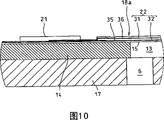
Next, will the structure of dummy electrode 18a be discussed.The basic structure of dummy electrode 18a is the same with aforesaid driving vibrator 18b.In other words, as Fig. 9 and shown in Figure 10, dummy electrode 18a also has a piezoelectric layer 22, comprise piezoelectrics 31 and lower piezoelectric body 32, and form blocks, and be formed with an electrode layer, between oscillating plate 15 and lower piezoelectric body 32 along the pressure chamber elongated lengthwise; An electrode layer is between piezoelectrics 31 and the lower piezoelectric body 32 on the interface; With an electrode layer, be on last piezoelectrics 31 surfaces relative with lower piezoelectric body 32.
In this embodiment, between oscillating plate 15 and lower piezoelectric body 32, after this electrode layer that is called as the first connection electrode 35, and on interface between last piezoelectrics 31 and the lower piezoelectric body 32, after this electrode layer that is called as the second connection electrode 36 all extends to the both sides of pressure chamber 13 to be electrically connected proximal pole public electrode 21 and discrete end points 19 along pressure chamber 13 length directions.
In other words, first connects electrode 35 from proximal pole public electrode 21, by the downside of lower piezoelectric body 32, arrive discrete end points 19, and the second connection electrode 36 by the downside of last piezoelectrics 31, arrives discrete end points 19 from proximal pole public electrode 21.In this embodiment, it is identical with drive electrode 24 with following public electrode 34 form to connect the electrode material that electrode uses.
In this structure, the discrete end points 19 on the dummy electrode 18a is electrically connected by being connected electrode 35,36 with proximal pole public electrode 21, and discrete end points 19 can be used as one provides end points that public electromotive force (ground connection for instance) is provided.Because the discrete end points 19 among discrete end points 19 that forms and the driving vibrator 18b is in same delegation, so actuating unit 3 can miniaturization.For electrical interconnection plate 4 and each discrete end points 19, the discrete end points 19 of the discrete end points 19 of false vibrator 18a and driving vibrator 18b can be electrically connected together, can increase work efficiency like this.
Connect the downside that electrode is placed on piezoelectric layer 22, can deckle-edged part not occur.Therefore can after assembling, wiring board 4 prevent effectively because defectives such as line broken circuit that burr partly cause and short circuits.Therefore, the stability of the less record head 1 of fault can be utilized fully.
In addition, connection electrode 35 and 36 is isolated in two-layer, thereby can guarantee enough thickness, and the resistance of electrode can be reduced to very low value like this.In addition, it is identical with drive electrode 24 with following public electrode 34 to form the electrode material that connects electrode 35 and 36 usefulness, so can prepare together with following public electrode 34 and drive electrode 24.In other words, first connects electrode 35 can prepare simultaneously with following public electrode 34, and the second connection electrode 36 can prepare simultaneously with drive electrode 24.Form the connection electrode with regard to not needing to handle especially like this, can enhance productivity.
Should be appreciated that to the invention is not restricted to described specific embodiment, do not depart from spirit and scope of the presently claimed invention, can these carry out combination and permutation part.
For instance, in an embodiment, piezoelectric vibrator 18 is sandwich constructions, and wherein upper and lower piezoelectrics 31 and 32 etc. are stacked, but the present invention also may be used on comprising the single layer structure piezoelectric vibrator of individual layer piezoelectric layer.For instance, for driving vibrator 18b, drive electrode 24 is formed between piezoelectric layer 22 and the oscillating plate 15, and last public electrode 33 and discrete end points 19 are formed on piezoelectric layer and oscillating plate 15 facing surfaces.For dummy electrode 18a, connect electrode and be formed between piezoelectric layer 22 and the oscillating plate 15.
Although the fluid jetting head with 1, one type of record head is described fluid jetting head as an example, the present invention also can be used for other fluid jetting head such as liquid crystal shower nozzle and pigment shower nozzle.
Claims (3)
1. fluid jetting head comprises:
Oscillating plate (15), formed the part of pressure chamber, described pressure chamber (13) is communicated with jet hole, drop sprays from described jet hole (10), and described pressure chamber is by being limited along first direction a plurality of first seamed edges that extend, that have first size and a plurality of second seamed edges of extending along the second direction that is basically perpendicular to described first direction, have less than second size of described first size;
Piezoelectric vibrator (18) overlays on the described oscillating plate, and feasible relative with described pressure chamber, described piezoelectric vibrator comprises:
Drive electrode (24) extends a seamed edge in described second seamed edge;
Last piezoelectrics (31) are layered on the described drive electrode, so that extend described second seamed edge; And
Last public electrode (33) is layered on the upper surface of described upward piezoelectrics; And
Discrete end points (19) is electrically connected to described drive electrode so that the driving signal to be provided to it, and this discrete end points extends to the first of one of extending in described second seamed edge of the described described upper surface of going up piezoelectrics, and with described go up public electrode away from.
2. fluid jetting head as claimed in claim 1, wherein said piezoelectric vibrator also comprises:
Following public electrode (34) is formed on the described oscillating plate, and is electrically connected to the described public electrode of going up; And
Lower piezoelectric body (32) is placed between described public electrode down and the described drive electrode.
3. fluid jetting head as claimed in claim 1, also comprise wiring board (4), described wiring board (4) is installed on the upper surface of the described upper surface of going up public electrode and described discrete end points, described wiring board (4) comprises contact terminal (20), described contact terminal (20) be positioned at described on position in the described first of piezoelectrics be connected to described discrete end points.
Applications Claiming Priority (2)
| Application Number | Priority Date | Filing Date | Title |
|---|---|---|---|
| JP2002099337A JP4277477B2 (en) | 2002-04-01 | 2002-04-01 | Liquid jet head |
| JP099337/2002 | 2002-04-01 |
Publications (2)
| Publication Number | Publication Date |
|---|---|
| CN1486792A CN1486792A (en) | 2004-04-07 |
| CN1301799C true CN1301799C (en) | 2007-02-28 |
Family
ID=28035906
Family Applications (2)
| Application Number | Title | Priority Date | Filing Date |
|---|---|---|---|
| CNB031215920A Expired - Fee Related CN1301799C (en) | 2002-04-01 | 2003-04-01 | Liquid spray head |
| CNU032444168U Expired - Lifetime CN2709015Y (en) | 2002-04-01 | 2003-04-01 | Liquid spray nozzle |
Family Applications After (1)
| Application Number | Title | Priority Date | Filing Date |
|---|---|---|---|
| CNU032444168U Expired - Lifetime CN2709015Y (en) | 2002-04-01 | 2003-04-01 | Liquid spray nozzle |
Country Status (6)
| Country | Link |
|---|---|
| US (1) | US7237878B2 (en) |
| EP (1) | EP1350626B1 (en) |
| JP (1) | JP4277477B2 (en) |
| CN (2) | CN1301799C (en) |
| AT (1) | ATE299800T1 (en) |
| DE (1) | DE60301028T2 (en) |
Families Citing this family (6)
| Publication number | Priority date | Publication date | Assignee | Title |
|---|---|---|---|---|
| JP4534137B2 (en) * | 2004-12-20 | 2010-09-01 | 富士フイルム株式会社 | Liquid discharge head and manufacturing method thereof |
| KR100694132B1 (en) * | 2005-06-28 | 2007-03-12 | 삼성전자주식회사 | Ink channel unit and method for manufacturing the same |
| CN101415560B (en) * | 2006-03-29 | 2010-12-22 | 京瓷株式会社 | Liquid discharge device |
| JP4428391B2 (en) * | 2007-03-14 | 2010-03-10 | セイコーエプソン株式会社 | Fluid ejecting head and fluid ejecting apparatus |
| JP6432729B2 (en) | 2014-10-02 | 2018-12-05 | セイコーエプソン株式会社 | Liquid ejecting head, liquid ejecting apparatus, and piezoelectric device |
| CN110121422B (en) * | 2017-07-15 | 2022-06-10 | 新科实业有限公司 | Thin film piezoelectric actuator |
Citations (7)
| Publication number | Priority date | Publication date | Assignee | Title |
|---|---|---|---|---|
| EP0636477A2 (en) * | 1993-07-30 | 1995-02-01 | Tektronix, Inc. | Method and apparatus for producing dot size modulated ink jet printing |
| EP0783965A2 (en) * | 1995-08-22 | 1997-07-16 | Nec Corporation | Fluid drop projecting apparatus and fluid drop projecting method |
| US5748214A (en) * | 1994-08-04 | 1998-05-05 | Seiko Epson Corporation | Ink jet recording head |
| US5983471A (en) * | 1993-10-14 | 1999-11-16 | Citizen Watch Co., Ltd. | Method of manufacturing an ink-jet head |
| EP1034931A1 (en) * | 1995-11-10 | 2000-09-13 | Seiko Epson Corporation | Ink jet type recording head |
| JP2000272129A (en) * | 1999-03-26 | 2000-10-03 | Nec Corp | Ink jet recording head and its manufacture |
| JP2002067311A (en) * | 2000-08-24 | 2002-03-05 | Seiko Epson Corp | Liquid jet device |
Family Cites Families (9)
| Publication number | Priority date | Publication date | Assignee | Title |
|---|---|---|---|---|
| US5402159A (en) * | 1990-03-26 | 1995-03-28 | Brother Kogyo Kabushiki Kaisha | Piezoelectric ink jet printer using laminated piezoelectric actuator |
| JP2913806B2 (en) * | 1990-09-14 | 1999-06-28 | ブラザー工業株式会社 | Piezoelectric inkjet printer head |
| EP0616890B1 (en) * | 1992-06-11 | 1997-10-01 | Seiko Epson Corporation | Ink jet head and method of manufacturing ink jet head |
| JP3366146B2 (en) | 1995-03-06 | 2003-01-14 | セイコーエプソン株式会社 | Ink jet head |
| JPH09277531A (en) | 1996-04-18 | 1997-10-28 | Ricoh Co Ltd | Ink-jet head |
| JPH11268269A (en) | 1998-03-26 | 1999-10-05 | Seiko Epson Corp | Ink-jet type recording head |
| JP3166741B2 (en) | 1998-12-07 | 2001-05-14 | 日本電気株式会社 | Ink jet recording head and method of manufacturing the same |
| JP2002103618A (en) * | 2000-01-17 | 2002-04-09 | Seiko Epson Corp | Ink jet recording head and its manufacturing method and ink jet recorder |
| JP3692895B2 (en) | 2000-03-07 | 2005-09-07 | ブラザー工業株式会社 | Piezoelectric inkjet printer head |
-
2002
- 2002-04-01 JP JP2002099337A patent/JP4277477B2/en not_active Expired - Lifetime
-
2003
- 2003-04-01 DE DE60301028T patent/DE60301028T2/en not_active Expired - Lifetime
- 2003-04-01 AT AT03007355T patent/ATE299800T1/en not_active IP Right Cessation
- 2003-04-01 CN CNB031215920A patent/CN1301799C/en not_active Expired - Fee Related
- 2003-04-01 CN CNU032444168U patent/CN2709015Y/en not_active Expired - Lifetime
- 2003-04-01 US US10/403,519 patent/US7237878B2/en not_active Expired - Fee Related
- 2003-04-01 EP EP03007355A patent/EP1350626B1/en not_active Expired - Lifetime
Patent Citations (7)
| Publication number | Priority date | Publication date | Assignee | Title |
|---|---|---|---|---|
| EP0636477A2 (en) * | 1993-07-30 | 1995-02-01 | Tektronix, Inc. | Method and apparatus for producing dot size modulated ink jet printing |
| US5983471A (en) * | 1993-10-14 | 1999-11-16 | Citizen Watch Co., Ltd. | Method of manufacturing an ink-jet head |
| US5748214A (en) * | 1994-08-04 | 1998-05-05 | Seiko Epson Corporation | Ink jet recording head |
| EP0783965A2 (en) * | 1995-08-22 | 1997-07-16 | Nec Corporation | Fluid drop projecting apparatus and fluid drop projecting method |
| EP1034931A1 (en) * | 1995-11-10 | 2000-09-13 | Seiko Epson Corporation | Ink jet type recording head |
| JP2000272129A (en) * | 1999-03-26 | 2000-10-03 | Nec Corp | Ink jet recording head and its manufacture |
| JP2002067311A (en) * | 2000-08-24 | 2002-03-05 | Seiko Epson Corp | Liquid jet device |
Also Published As
| Publication number | Publication date |
|---|---|
| JP4277477B2 (en) | 2009-06-10 |
| CN2709015Y (en) | 2005-07-13 |
| ATE299800T1 (en) | 2005-08-15 |
| US7237878B2 (en) | 2007-07-03 |
| DE60301028D1 (en) | 2005-08-25 |
| EP1350626A1 (en) | 2003-10-08 |
| JP2003291336A (en) | 2003-10-14 |
| CN1486792A (en) | 2004-04-07 |
| EP1350626B1 (en) | 2005-07-20 |
| US20030210308A1 (en) | 2003-11-13 |
| DE60301028T2 (en) | 2006-04-20 |
Similar Documents
| Publication | Publication Date | Title |
|---|---|---|
| US7922300B2 (en) | Liquid ejecting apparatus, method for manufacturing liquid ejecting apparatus, and ink-jet printer | |
| CN1199797C (en) | Liquid jetting head | |
| CN1269299C (en) | Piezoelectric actuator, liquid spray nozzle containing it and manufacturing method thereof | |
| CN1131092A (en) | Printing head for ink jet printer and method for producing the same | |
| CN100340404C (en) | Liquid injection head | |
| JPH08300650A (en) | Ink jet printing head and production thereof | |
| US7512035B2 (en) | Piezoelectric actuator, liquid transporting apparatus, and method of producing piezoelectric actuator | |
| CN1301799C (en) | Liquid spray head | |
| CN102673151B (en) | The manufacture method of ink gun and ink gun | |
| EP1997638A1 (en) | Method of forming an array of piezoelectric actuators on a membrane | |
| CN1612808A (en) | Piezoelectric actuator and fluid injection head having the same | |
| US20020051041A1 (en) | Piezoelectric ink jet printer head and method for manufacturing same | |
| JP2006019718A (en) | Method of manufacturing piezoelectric actuator, the piezoelectric actuator and ink jet head | |
| JP4135448B2 (en) | Method for manufacturing droplet ejecting apparatus | |
| JP2004096068A (en) | Piezoelectric element, piezoelectric actuator, and liquid injection head | |
| JP2007268838A (en) | Inkjet head | |
| JPH09300632A (en) | Ink-jet recording device | |
| CN1572500A (en) | Piezoelectric converter | |
| JPH06198876A (en) | Ink jet printing head and its production | |
| CN100343059C (en) | Method for manufacturing inkjet printing head | |
| JPH05198861A (en) | Laminated piezoelectric displacement element and ink jet type print head | |
| JPH1134323A (en) | Ink-jet head | |
| JP4456357B2 (en) | Piezoelectric actuator and inkjet recording head | |
| JP2004114558A (en) | Inkjet printer head and manufacturing method therefor | |
| JP2004357438A (en) | Piezoelectric actuator and ink-jet recording head |
Legal Events
| Date | Code | Title | Description |
|---|---|---|---|
| C06 | Publication | ||
| PB01 | Publication | ||
| C10 | Entry into substantive examination | ||
| SE01 | Entry into force of request for substantive examination | ||
| C14 | Grant of patent or utility model | ||
| GR01 | Patent grant | ||
| C17 | Cessation of patent right | ||
| CF01 | Termination of patent right due to non-payment of annual fee |
Granted publication date: 20070228 Termination date: 20130401 |