CN1299233C - Smart card - Google Patents
Smart card Download PDFInfo
- Publication number
- CN1299233C CN1299233C CNB011454814A CN01145481A CN1299233C CN 1299233 C CN1299233 C CN 1299233C CN B011454814 A CNB011454814 A CN B011454814A CN 01145481 A CN01145481 A CN 01145481A CN 1299233 C CN1299233 C CN 1299233C
- Authority
- CN
- China
- Prior art keywords
- card
- user
- signal
- fingerprint
- smart card
- Prior art date
- Legal status (The legal status is an assumption and is not a legal conclusion. Google has not performed a legal analysis and makes no representation as to the accuracy of the status listed.)
- Expired - Fee Related
Links
Images

Abstract
The present invention relates to a smart card which is used with security entrances, such as a transportation turnstile, a dwelling access door, or vehicle parking equipment, etc. for verifying and checking passing authorization. A fingerprint sensor is positioned on the main surface of the card corresponding to the positions on which a thumb and a finger are naturally placed. A fingerprint pattern signal which is generated by the fingerprint sensor is checked by a real version stored in a non-volatile memory of the card through using a processor in the inner part of the card. The result of the checking is transmitted to a relative external security entrance through an r. f. circuit which is also used for receiving r. f. energy for supplying D. C. power used by a circuit in the card. The card can by used busily without stopping at a check point, so a user can pass the traffic flow of the check point conveniently.
Description
Technical field
This invention is usually directed to smart card, especially relates to a kind of improvement smart card architecture that improves ability to work that has.
Background technology
Smart card is known at present, and comprise a card graphic data token usually with the active system element that is integrated in this card structure inside, the interactive mode that is used to start this card and several data disposal system is used, wherein one of this several data disposal system such as the credit card charge system, the debit card system that start the point-of-sale purchasing transaction, the fee system that is used for public transport, secure access equipment and any needs can with the application of an interactional data markers of data disposal system.Smart card has two kinds of basic configuration, and a kind of requirement has directly with card reader, the positive contact (using the card of resistance contact such as those), and another kind only requires near this card reader (using the card of inductance or capacitive character transfer element such as those).Two kinds of configurations are all integrated several by the needed primary element of equipment that suitably works in the physical card inside configuration usually.These elements comprise: an I/O data transmission circuit; Local data's processor; Certain type nonvolatile memory is used between effective service life in these card storage inside data, and the program of storing certain form works with the external data disposal system to start this card; And power delivery circuit.Just directly contact smart card, the I/O data transmission circuit uses resistance to contact with the power delivery circuit usually, and its allows to be sent to by the direct current DC power supply that the card reader unit provides at the inner element of this card, and a data transfer path is provided.With regard to non-contacting smart card, I/O data transmission circuit and power delivery circuit adopt a r.f. energy receiving circuit usually, and it comprises the energy that is used for receiving is converted into available direct current form from the external source of a r.f. form circuit.This r.f. energy receiving circuit comprises an inductance usually, and it also is used to provide a data transfer path.Can from RacomSystems company, obtain, be entitled as the summary of having set forth in the publication of " About Smart Cards " current smart card techniques at one.Therefore the open of this publication be comprised in herein as a reference.
Proposed to comprise that an authentication mechanism is used to stop the smart card of this card by everyone use except the authorized user.The safety verification mechanism that is proposed up to now is at an inner finger-printer reader and the interlock circuit of using of this card self, it can read unique finger print of this user or thumbprint, with the fingerprint that reads and one known be that the storage version of authentic work compares, and if this two version match then allow to use this card to be used for transaction.A kind of like this description of safety intelligent card can be at United States Patent (USP) 5 that announce, that be entitled as " CREDIT CARD WITH DIGITIZED FINGER PRINT AND READING APPARATUS " on Dec 5 nineteen ninety-five, 473,144, and the United States Patent (USP) 5 that is entitled as " IC CARD WITH INDIVIDUALAUTHENTICATION FUNCTION ", 180, find in 901, these be disclosed in this be comprised in as a reference.
In such smart card known, that use directly contacts between card and reader device, card must be inserted in the groove (such as the groove in ' 144 equipment 18), and user's finger or thumb must be crushed on a stayed surface (such as the scanning screen 20 in ' 144 equipment) and go up so that carry out proof procedure.In the smart card apparatus shown in ' 901 patents, it seems also to have used direct contact, and this card must be placed on the firm area supported so that allow user's finger firmly to be pressed on the fingerprint sensor zone 1 and 3 so that allow proof procedure correctly to carry out.
Use although such scheme is very suitable for the direct contact that the inherence requires smart card to be maintained fixed to continue for some time in card reader, when this scheme is attempted to be used for non-contacting smart card, just run into problem.The principal advantages of contactless smart card is the following fact, that is: this card can be read by by leaps and bounds, and does not need the user to stop in the card reader position, this card is inserted in the card reader, waits for that proof procedure finishes, fetches card from reader then.On the contrary, in the device of a non-contact card, the user if with card be placed on reader near, usually simultaneously the direction along safety entrance (for example transportation system's turnsile or automatic safe gate or door) moves on, and proof procedure is proceeded when the user advances.If licensing process is successful, then the user does not need through safety entrance to suspend during this process.This advantage is especially effective in high throughput is used, and the result of expectation is the through-flow combination of continuous stream of secure access and normal speed in this high throughput is used.The smart card system of known use finger-mark check provides the secure access of height really, yet this system will stand following shortcoming: need suspend in circulation stream when user's fingerprint is being examined authenticity.
Summary of the invention
The present invention comprises a kind of smart card, it is veritified fingerprint and is integrated in the physical card structure, and allow to read the user individual fingerprint and without any need for the surface element that reads of static state, so that this card can be by the visit that is used to control to a safety entrance by leaps and bounds.
A broad aspect, the present invention comprises a physical card structure, thus it have one be positioned at lip-deep fingerprint registration zone of this card, be used to allow the user hold this card with depress finger or thumbprint and start the device of registration with this fingerprint registration zone and be positioned at this card inside, electronic circuit that the physics finger print information that is used for offering this fingerprint registration zone is converted into the electric fingerprint signal that the individual fingerprint authenticity that is used to carry out this user checks.
This starter gear preferably comprises Sensor section on this card surface, the fingerprint part that it is positioned at when this card is held by user thumb or finger is the position of placement naturally, so that when the user grasps this card in appropriate mode, can set up firm contact automatically, and can generate reliable signal.
This electronic circuit comprises and is used for carrying out the fingerprint authentication collation process and being used to send one in this card inside itself fully passing through/ arrive by signal the circuit component of safety verification point.This circuit comprises the true version that a nonvolatile memory is used to store the fingerprint of authorized user, and a processor is used for these known version and the current fingerprint signal that is generated by fingerprint sensor are compared.A r.f. transmission circuit provides a data transfer path between card and any external unit, and can also make the r.f. energy be transferred to the inner circuit component of this card from an external source.
The invention provides the relatively high security relevant, and do not have to hinder circulation stream by this safety verification point with individual finger-mark check.
In order to fully understand characteristic of the present invention and advantage, should carry out detailed description subsequently in conjunction with the accompanying drawings.
Description of drawings
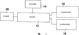
Fig. 1 is a kind of integrated block scheme of non-contact transmission smart card of the present invention;
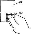
Fig. 2 is the surperficial view of first card that has shown the fingerprint registration zone of an integrated smart card of the present invention;
Fig. 3 is the view of the card reverse side of an integrated smart card of the present invention; And
Fig. 4-the 5th has illustrated the interactive synoptic diagram between a user's opposing thumb and finger and this fingerprint sensor.
Embodiment
Below referring to accompanying drawing, Fig. 1 is a kind of integrated block scheme of non-contact transmission smart card of the present invention.As shown in this accompanying drawing, this smart card comprises a microprocessor 12, fingerprint memory 14, front finger-printer reader 16, a reverse side finger-printer reader 18 and a r.f. transmission circuit 20.Microprocessor 12 can comprise many commercially available, can provide any one in the required microprocessor of wanting control as described below and data processing function of smart card, such as a kind of flush bonding processor in the PIC family of this equipment that can from the Microchip Technology company of Arizona state Chandler, obtain.Fingerprint memory 14 comprises a non-volatile memory cells with enough memory capacity, so that for good and all store the digital version of one or more individual fingerprints of authorized user, preferably a thumbprint and a finger print (preferably the forefinger fingerprint and the thumbprint of the same hand).The known type that is suitable for use as the non-volatile memory device of fingerprint memory 14 comprises flash memory, PROM, EEPROM and disclosed magnetic memory cell in this piece patent documentation below, this piece document is: the U.S. Patent No. 5 of publishing on June 30th, 1992, be entitled as " Thin Film Magnetic Core Memory And Method Of Making Same ", 126,971, in this is included in this piece document as a reference.
When finger- printer reader 16 and 18 can comprise on any type of part that can be pressed in finger-printer reader place on the smart card surface securely in user's finger or thumb part, the finger-printer reader equipment of this user's of generation expression the finger or the individual fingerprint pattern electric signal of thumb.The ridge that these electric signal are usually found on the pulp of one of indication finger or thumb endways and between first joint and unique pattern of paddy, and this pattern is a highly reliably indication of authenticity.Reader 16 and 18 can be combined in disclosed principle in above referenced two patent ' 144 and ' 901, perhaps can comprise other equivalent of the apparatus known, can generate required pattern signal separately from finger or thumb press.
R.f. transmission circuit 20 provides energy and data transmission between inner smart card element and external unit, and comprise a loop inductance usually, be used for energy and data that sensing provides from these external units, and the circuit that is used for handling in a suitable manner energy and data-signal.Sort circuit is known in the art, and comprises usually and be used to separate the circuit of r.f. energy and data-signal and be used for circuit data cached on the input and output direction.
Fig. 2 and 3 has illustrated the smart card pro and con in most preferred embodiment of the present invention respectively, and the fingerprint sensor zone is in each lip-deep optimum position.With reference to figure 2, be positioned in the fingerprint sensor zone 22 on the smart card front 23: greatly about positive 23 right lower quadrant, when hold with a firm grip by the user card when (as shown in Figure 4) this user's opposing thumb fingerprint partly will carry out firm position contacting.With reference to figure 3, be positioned at: greatly about the left lower quadrant of reverse side 25, partly will carry out firm position contacting when card this user's when (as shown in Figure 5) that holds with a firm grip by the user finger print in the fingerprint sensor zone 24 on the smart card reverse side 25.Because this placement in this fingerprint sensor zone, when holding this card securely with a firm grip by the user, the fingerprint of thumb and finger is carried out operational the contact with the fingerprint sensor zone securely.As a result of, this card can be by use by leaps and bounds and can be as prior art equipment be not desired any support platform of needs.
In use, being written into fingerprint memory 14 by the one or more fingerprints with authorized user is ready to smart card.This carries out in some authorizes place usually, such as card publisher's (for example the administration office of the security offices in bank, parking place, course line travelling office, control visit group, forwarder's bill purchase venue, etc. similar means) a branch offices.In case individual fingerprint for good and all is stored in the storer 14, this card just can be used in combination with the safety verification point of control corresponding access system.At each such check point, a remote location is provided, it will be used to realize that safe access control necessary electronic and mechanical organ combine.This external unit and smart card interact in two ways: the first, by a r.f. energy source is provided so that smart card electronic equipment energising; The second, by receive the signal that allows visit/denied access from this smart card.Check inner checking of card itself by means of a verification algorithm execution of using by microprocessor 12.If the result who is checked by the checking of microprocessor execution shows that this card is just carried by authorized user, then one of microprocessor issues allows interrogation signal, and this signal is transferred to the remote location via r.f. transmission circuit 20.In case receive this signal by the remote location, this place is just carried out the necessary control function and is obtained visit to allow this user.Otherwise, denied access then.
Although ought be in fact for economic and simple reason, when preferentially having selected the flat card surface topography as shown in Fig. 2-5 for use, be understood that and can adopt other surface topography according to expectation.For example, the card main body can be made into a three-dimensional token with essence thickness, has contoured part to be formed for the natural embedding zone of thumb or finger on one or two main surface.
Will be obvious now, the smart card of making according to teaching of the present invention provides two advantages: provide high relatively safety by the fingerprint authentication technology, and the uncrossed circulation stream that passes through the control area.The present invention can be used in the broad variety application that needs the smart card techniques performance, and this will be conspicuous for a person skilled in the art.The present invention is specially adapted to those application that relate to the uncrossed circulation stream of needs, such as transportation system expense charge equipment, airport security check point, motor vehicles toll charge station, visit an inhabitation group controllably, and the application that combines of any requirement that security need be measured and required vehicle or individual smooth flow.The present invention can be arranged to independent access control, or is used in conjunction with the fee control that conducts interviews, as during a transportation system or toll bar are used.
The right hand that the present invention can be arranged to as shown in the figure uses, is used for the left hand use and is used for single or two fingerprint authentication.For example, with regard to single fingerprint authentication, have only a fingerprint sensor zone 22 or 24 to be incorporated in the smart card, and the set of single corresponding true fingerprint signal is stored in the storer 14.In addition, the present invention can be configured to the right hand or left hand all uses.In such application, fingerprint sensor zone 22,24 is positioned near the center of this card bottom, so that make the thumb of a right hand or left hand and/or forefinger fingerprint be registered.
Although more than provide the complete sum of most preferred embodiment of the present invention comprehensively open, can carry out various modifications for a person skilled in the art, replace structure and equivalence.For example, be described though be used for the instantiation of microprocessor 12, fingerprint memory 14 and fingerprint sensor 16,18, can be according to requiring to select the miscellaneous equipment type.Therefore, more than should not be considered to limit the present invention, the present invention is defined by additional claims.
Claims (4)
1. smart card that is used for secured user's verification system, described card comprises:
Card main body with front and back side;
A fingerprint sensor that carries by described card, has the first on the one side at the described front that is arranged in described card and the back side, be used to provide the live signal of a finger print in the described first that user of expression is pressed in described sensor, and be arranged in second portion on the another side at the described front of described card and the back side, be used to provide the live signal of a thumbprint on the described second portion that the described user of expression is pressed in described sensor, described first is positioned on the described front and the described back side of described card with described second portion with relative like this position, make whereby when described user holds described card, described finger print and described thumbprint can with described first and described second portion aim at respectively;
Be used for holding by described user and described user's finger and thumb allows described fingerprint sensor that described signal is provided when contacting respectively with described first and second parts of described sensor and do not need the device of EXS help when described card; And
At the inner demo plant of this card, be used for generating electric validation signal from described fingerprint sensor signal,
Whereby, described live signal and described validation signal can produce when mobile and do not need to support described card with an external support at the described row that sticks into.
2. the smart card that is used for secured user's verification system as claimed in claim 1, it is characterized in that: described demo plant comprises a fingerprint memory in described card, be used to store known real finger fingerprint and thumbprint signal, and processor device, be used for described real finger print and thumbprint signal and described live signal are compared.
3. the smart card that is used for secured user's verification system as claimed in claim 1, it is characterized in that: described card further comprises a r.f. transmission circuit, be used for receiving the r.f. energy, and be used to be enabled in data transmission between described card and the outside relevant device from a relevant external source.
4. the smart card that is used for secured user's verification system as claimed in claim 1 is characterized in that: described demo plant further comprises and is used to generate an access control signal to be used for controlling the device of an external reference opertaing device.
Priority Applications (1)
| Application Number | Priority Date | Filing Date | Title |
|---|---|---|---|
| CNB011454814A CN1299233C (en) | 2001-12-29 | 2001-12-29 | Smart card |
Applications Claiming Priority (1)
| Application Number | Priority Date | Filing Date | Title |
|---|---|---|---|
| CNB011454814A CN1299233C (en) | 2001-12-29 | 2001-12-29 | Smart card |
Publications (2)
| Publication Number | Publication Date |
|---|---|
| CN1430178A CN1430178A (en) | 2003-07-16 |
| CN1299233C true CN1299233C (en) | 2007-02-07 |
Family
ID=4678196
Family Applications (1)
| Application Number | Title | Priority Date | Filing Date |
|---|---|---|---|
| CNB011454814A Expired - Fee Related CN1299233C (en) | 2001-12-29 | 2001-12-29 | Smart card |
Country Status (1)
| Country | Link |
|---|---|
| CN (1) | CN1299233C (en) |
Families Citing this family (4)
| Publication number | Priority date | Publication date | Assignee | Title |
|---|---|---|---|---|
| NZ571961A (en) * | 2006-03-27 | 2011-10-28 | Fabrizio Borracci | A method for making a secure personal card and its working process |
| CN102542693B (en) * | 2010-12-14 | 2016-05-11 | 金鹏科技有限公司 | Electronic service system, for the charhing unit of electronic service system |
| CN105205663A (en) * | 2015-09-14 | 2015-12-30 | 南昌欧菲生物识别技术有限公司 | Chip card and password-free authentication method based on chip card |
| KR101899334B1 (en) * | 2016-12-19 | 2018-09-17 | 코나아이 (주) | Fingerprint recognition card and method for operating power of the fingerprint recognition card |
Citations (4)
| Publication number | Priority date | Publication date | Assignee | Title |
|---|---|---|---|---|
| DE19648767A1 (en) * | 1995-12-21 | 1997-06-26 | Siemens Ag Oesterreich | Electronic chip card identification system |
| US5815252A (en) * | 1995-09-05 | 1998-09-29 | Canon Kabushiki Kaisha | Biometric identification process and system utilizing multiple parameters scans for reduction of false negatives |
| EP0994439A2 (en) * | 1998-10-13 | 2000-04-19 | Sony Corporation | IC card |
| US6325285B1 (en) * | 1999-11-12 | 2001-12-04 | At&T Corp. | Smart card with integrated fingerprint reader |
-
2001
- 2001-12-29 CN CNB011454814A patent/CN1299233C/en not_active Expired - Fee Related
Patent Citations (4)
| Publication number | Priority date | Publication date | Assignee | Title |
|---|---|---|---|---|
| US5815252A (en) * | 1995-09-05 | 1998-09-29 | Canon Kabushiki Kaisha | Biometric identification process and system utilizing multiple parameters scans for reduction of false negatives |
| DE19648767A1 (en) * | 1995-12-21 | 1997-06-26 | Siemens Ag Oesterreich | Electronic chip card identification system |
| EP0994439A2 (en) * | 1998-10-13 | 2000-04-19 | Sony Corporation | IC card |
| US6325285B1 (en) * | 1999-11-12 | 2001-12-04 | At&T Corp. | Smart card with integrated fingerprint reader |
Also Published As
| Publication number | Publication date |
|---|---|
| CN1430178A (en) | 2003-07-16 |
Similar Documents
| Publication | Publication Date | Title |
|---|---|---|
| US6360953B1 (en) | Secure print sensing smart card with on-the-fly-operation | |
| EP1326196B1 (en) | Fingerprint sensing smart card with on-card fingerprint comparison | |
| US6454173B2 (en) | Smart card technology | |
| EP0784290B1 (en) | An apparatus for issuing data cards | |
| US8103881B2 (en) | System, method and apparatus for electronic ticketing | |
| CA1223614A (en) | Secure transaction card and verification system | |
| EP0619564B1 (en) | Automated transaction system with insertable cards for transferring account data | |
| US6089451A (en) | Systems for authenticating the use of transaction cards having a magnetic stripe | |
| US4900903A (en) | Automated transaction system with insertable cards for transferring account data | |
| DK1725995T3 (en) | Credit card and secured data activation system | |
| EP1041523A2 (en) | Transaction recordal and validation | |
| NL1020903C2 (en) | System and method for automatically verifying the holder of an authorization document and automatically determining the authenticity and validity of the authorization document. | |
| WO2001078021A2 (en) | Biometric authentication card, system and method | |
| KR20010039242A (en) | Authentication smart card system and controlling method thereof using multi - biometric informations | |
| US20030046555A1 (en) | Identity verification using biometrics | |
| KR100275638B1 (en) | Ic card and personal data identifying system operative therewith | |
| CN1299233C (en) | Smart card | |
| TW421768B (en) | Contactless payment method and device using a rechargeable medium | |
| JP5550394B2 (en) | Ticket medium processing apparatus, ticket medium processing system, and ticket medium processing method | |
| WO1997015032A1 (en) | System for the safe authentication and management of registered credit instruments and documents | |
| US20080265017A1 (en) | Credit card and security system | |
| WO2002071225A1 (en) | Identity verification using biometrics in analog format | |
| JPH0950504A (en) | Play information medium | |
| JP2005135059A (en) | Automatic ticket gate system with face collating function, face collating and registering server, and automatic ticket gate with face collating function | |
| CN102034308A (en) | Automatic vending system and method, magnetic valuable notes and automatic vending machine |
Legal Events
| Date | Code | Title | Description |
|---|---|---|---|
| C06 | Publication | ||
| PB01 | Publication | ||
| C10 | Entry into substantive examination | ||
| SE01 | Entry into force of request for substantive examination | ||
| C14 | Grant of patent or utility model | ||
| GR01 | Patent grant | ||
| C17 | Cessation of patent right | ||
| CF01 | Termination of patent right due to non-payment of annual fee |
Granted publication date: 20070207 Termination date: 20131229 |