CN1278585C - Loudspeaker - Google Patents
Loudspeaker Download PDFInfo
- Publication number
- CN1278585C CN1278585C CNB028032209A CN02803220A CN1278585C CN 1278585 C CN1278585 C CN 1278585C CN B028032209 A CNB028032209 A CN B028032209A CN 02803220 A CN02803220 A CN 02803220A CN 1278585 C CN1278585 C CN 1278585C
- Authority
- CN
- China
- Prior art keywords
- mentioned
- magnet
- yoke
- loud speaker
- coil
- Prior art date
- Legal status (The legal status is an assumption and is not a legal conclusion. Google has not performed a legal analysis and makes no representation as to the accuracy of the status listed.)
- Expired - Fee Related
Links
Images


Classifications
-
- H—ELECTRICITY
- H04—ELECTRIC COMMUNICATION TECHNIQUE
- H04R—LOUDSPEAKERS, MICROPHONES, GRAMOPHONE PICK-UPS OR LIKE ACOUSTIC ELECTROMECHANICAL TRANSDUCERS; DEAF-AID SETS; PUBLIC ADDRESS SYSTEMS
- H04R9/00—Transducers of moving-coil, moving-strip, or moving-wire type
- H04R9/02—Details
- H04R9/025—Magnetic circuit
-
- H—ELECTRICITY
- H04—ELECTRIC COMMUNICATION TECHNIQUE
- H04R—LOUDSPEAKERS, MICROPHONES, GRAMOPHONE PICK-UPS OR LIKE ACOUSTIC ELECTROMECHANICAL TRANSDUCERS; DEAF-AID SETS; PUBLIC ADDRESS SYSTEMS
- H04R7/00—Diaphragms for electromechanical transducers; Cones
- H04R7/02—Diaphragms for electromechanical transducers; Cones characterised by the construction
- H04R7/04—Plane diaphragms
-
- H—ELECTRICITY
- H04—ELECTRIC COMMUNICATION TECHNIQUE
- H04R—LOUDSPEAKERS, MICROPHONES, GRAMOPHONE PICK-UPS OR LIKE ACOUSTIC ELECTROMECHANICAL TRANSDUCERS; DEAF-AID SETS; PUBLIC ADDRESS SYSTEMS
- H04R9/00—Transducers of moving-coil, moving-strip, or moving-wire type
- H04R9/02—Details
- H04R9/04—Construction, mounting, or centering of coil
- H04R9/046—Construction
- H04R9/047—Construction in which the windings of the moving coil lay in the same plane
-
- H—ELECTRICITY
- H04—ELECTRIC COMMUNICATION TECHNIQUE
- H04R—LOUDSPEAKERS, MICROPHONES, GRAMOPHONE PICK-UPS OR LIKE ACOUSTIC ELECTROMECHANICAL TRANSDUCERS; DEAF-AID SETS; PUBLIC ADDRESS SYSTEMS
- H04R2209/00—Details of transducers of the moving-coil, moving-strip, or moving-wire type covered by H04R9/00 but not provided for in any of its subgroups
- H04R2209/022—Aspects regarding the stray flux internal or external to the magnetic circuit, e.g. shielding, shape of magnetic circuit, flux compensation coils
-
- H—ELECTRICITY
- H04—ELECTRIC COMMUNICATION TECHNIQUE
- H04R—LOUDSPEAKERS, MICROPHONES, GRAMOPHONE PICK-UPS OR LIKE ACOUSTIC ELECTROMECHANICAL TRANSDUCERS; DEAF-AID SETS; PUBLIC ADDRESS SYSTEMS
- H04R9/00—Transducers of moving-coil, moving-strip, or moving-wire type
- H04R9/06—Loudspeakers
Abstract
A loudspeaker comprising at least a magnet 27, yoke24 fixed on the bottom surface of the magnet, flat plate 26 fixed on the top surface of the magnet, magnetic circuit 29having a magnetic gap 28 formed between the plate and the yoke, and planar diaphragm 23 having a coil 21 disposed above the magnetic gap. The width of the magnet is larger than that of the plate, and at least a part of the top surface of the magnet is exposed to directly face the diaphragm. This constitution enables an increase in the magnet volume without enlarging the magnetic circuit. In addition, a magnetic flux can be concentrated on the upper part of the magnetic gap to make the magnetic circuit small-sized and high-efficient. This results in the supply of a small-sized and high-efficient high-pitched sound loudspeaker.
Description
Technical field
The present invention relates to be used for the electrodynamic loudspeaker of various stereo sets, relate to the loud speaker of the sound of the high range that is suitable for regenerating especially.
Background technology
Usually the loud speaker of high pitch of claiming to be used to regenerate is a tweeter.In recent years, be used for the regeneration 20KHz of high pitch materialization with the DVD sound equipment of the music source of upper frequency, the listing of super sound equipment, 20KHz is above, ideal is the sound to the frequency of 100KHz to require tweeter also can regenerate.Have, be accompanied by the miniaturization of stereo set complete machine, all loud speakers also trend towards miniaturization.
For this trend, there is multinomial problem in the high pitch aspect that the tweeter of present use dome-shaped oscillating plate is used to regenerate more than the 20KHz.
As the method for the problem that solves so-called actuating force decay at such high band, proposed to change the loud speaker that is called the reed tweeter of tweeter structure.
Fig. 9 A~Fig. 9 D, Figure 10 illustrates existing reed speaker.In Fig. 9 A~Fig. 9 D, Figure 10, oscillating plate 23 is made of diaphragm 20, coil 21 and frame 22, have, magnetic circuit 29 is made of end yoke 24, outside yoke 25, plate 26, magnet 27 and two magnetic gap 28 again, and magnetic gap 28 is made of the outer peripheral face of plate 26 and the inner peripheral surface of outside yoke 25.Here, configuration oscillating plate 23 will make the upper face side of coil 21 at magnetic gap 28, at framework 30 internal fixation oscillating plates 23 and magnetic circuit 29.Have again, generally between magnetic circuit 29 and oscillating plate 23, insert buffer insulation material 31.
The reed tweeter forms such structure, when input current on coil 21, with diaphragm 20 all-in-one-piece coils 21 on actuating force takes place, so the actuating force of coil 21 can not decay and driven diaphragm 20 is emitted sound wave, forms the tweeter of the above sound wave of suitable regeneration 20KHz.
But above-mentioned reed tweeter: the width of (1) its magnetic gap 28 is wideer several times than the width of the magnetic gap of the tweeter of general use dome-shaped oscillating plate, and its magnetic flux density is low.Have again, because can not utilize magnetic flux in the most concentrated magnetic gap of magnetic flux 28, so magnetic circuit 29 efficient are not high on the structure.
Promptly, occasion at existing reed tweeter, shown in Fig. 9 A~Fig. 9 D, in order to make flux concentration in magnetic gap 28, want bonding identical with the width of magnet 27 at least plate 26, and make the shape of the outside yoke 25 of magnetic gap 28 sides become convex, and magnetic flux is concentrated in magnetic gap 28.Have again, produce the magnetic saturation states in the outside yoke 25 and magnetic flux is spread a little upward.But because also diffusion downwards of magnetic flux, so can not be effectively concentrate magnetic flux from magnet 27 to the top of the magnetic gap 28 at coil 21 places.
(2) because the size of the magnetic flux density of the regeneration acoustic pressure of loud speaker and magnetic gap 28 is directly proportional, so for guaranteeing that acoustic pressure is necessary to strengthen magnet 27.Have, increase the plate 26 that 27 of magnet are bonded on the magnet 27 and also enlarges, this can cause end yoke 24, outside yoke 25 also to enlarge, and can form magnetic circuit 29 increases, and the trend of this and present loud speaker miniaturization is disproportionate.
(3) have again, in existing loud speaker, because the direction of the magnetic flux of magnetic gap 28 reverses between two magnetic gap 28A, 28B as illustrated in fig. 10, so the sense of current is reversed at coil portion 21A, 21B.Though the distribution that side's conduct of this inversion section is connected with lead partly uses, also comprising opposite side becomes the part that is subjected to less than magnetic field induction, and this becomes the main cause of the service efficiency reduction that makes coil.Thereby, will be accompanied by the magnetic circuit maximization because will obtain big actuating force, become the thing of difficulty so realize miniaturization and.
Summary of the invention
The present invention solves above-mentioned problem, the loud speaker of the high-quality that the magnetic circuit miniaturization can fully guarantee to regenerate acoustic pressure simultaneously is provided.
The formation of loud speaker of the present invention comprises magnetic circuit and plane oscillating plate.Described magnetic circuit by at least one block of magnet, be bonded in yoke below the magnet, be bonded in flat plate above the magnet, be formed at above-mentioned yoke the side the outside yoke or be formed at two convex yokes, the magnetic gap that between above-mentioned plate and above-mentioned outside yoke or convex yoke, forms on the yoke between the magnet and constitute; Described oscillating plate has the coil that is configured in the magnetic gap top.The width of the magnet of loud speaker of the present invention is wideer than dull and stereotyped width, exposed, the direct subtend oscillating plate of top at least a portion of magnet.According to formation of the present invention, do not increase magnetic circuit and can enlarge the volume of magnet, and can therefore can realize magnetic circuit miniaturization, high efficiency to the top of magnetic gap concentration magnetic flux, its result can provide small-sized and high efficiency tweeter.
Description of drawings
Figure 1A is the vertical view of oscillating plate of the loud speaker of one embodiment of the invention;
Figure 1B is the vertical view of magnetic circuit of the loud speaker of one embodiment of the invention;
Fig. 1 C is the A-B profile of Figure 1B;
Fig. 1 D is the profile of an embodiment of loud speaker of the present invention;
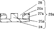
Fig. 2 A is the vertical view of the magnetic circuit of another embodiment of the present invention;
Fig. 2 B is the A-B profile of Fig. 2 A;
Fig. 2 C is the profile of the loud speaker of another embodiment of the present invention;
Fig. 3 A is the vertical view of the oscillating plate of the loud speaker of an embodiment more of the present invention;
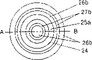
Fig. 3 B is the vertical view of the magnetic circuit of the loud speaker of an embodiment more of the present invention;
Fig. 3 C is the A-B profile of Fig. 3 B;
Fig. 3 D is the profile of the loud speaker of an embodiment more of the present invention;
Fig. 4 A is the vertical view of magnetic circuit of the loud speaker of another embodiment of the present invention;
Fig. 4 B is the A-B profile of Fig. 4 A;
Fig. 4 C is the profile of the loud speaker of another embodiment of the present invention;
The exploded perspective view of the loud speaker of Fig. 5 fifth embodiment of the present invention;
Fig. 6 is the side cut away view of the relation of explanation oscillating plate and magnetic circuit;
Fig. 7 is the vertical view of oscillating plate;
Fig. 8 is the vertical view of oscillating plate of the loud speaker of fifth embodiment of the invention;
Fig. 9 A is the vertical view of the oscillating plate of existing reed tweeter;
Fig. 9 B is the vertical view of the magnetic circuit of existing reed tweeter;
Fig. 9 C is the A-B profile of Fig. 9 B;
Fig. 9 D is the profile of existing reed tweeter;
Figure 10 is the exploded perspective view of existing reed tweeter.
Symbol description
20 ... diaphragm; 21 ... coil; 22 ... frame; 23 ... oscillating plate; 24 ... end yoke; 25 ... the outside yoke; 25a ... the convex yoke; 26,26a, 26b ... dull and stereotyped; 27,27a, 27b ... magnet; 28 ... magnetic gap; 28a ... inboard magnetic gap; 28b ... outside magnetic gap; 29,29a ... magnetic circuit
Embodiment
One embodiment of loud speaker of the present invention is described below with reference to the accompanying drawings.Have again, in the identical part of the existing technology of explanation neutralization additional identical numbering, omission explanation.
(embodiment one)
First embodiment of loud speaker of the present invention is described according to the reed tweeter of Figure 1A~Fig. 1 D.
In Figure 1A~Fig. 1 D, oscillating plate 23 is made of diaphragm 20, coil 21 and frame 22.Have, the reed tweeter of present embodiment has magnetic circuit 29 again, and it comprises: the end yoke 24 that is provided with outside yoke 25; Be installed on the end yoke 24, at the magnet 27 of vertical direction magnetize; Be contained in the plate 26 on the magnet 27; Two magnetic gap 28 that constitute by the inner peripheral surface of the outer peripheral face of plate 26 and outside yoke 25.
The reed tweeter of aforesaid present embodiment and the difference of existing reed tweeter are the width structures wideer than the width of plate 26 that forms magnet 27.Formation by present embodiment can obtain following effect.
(1) on magnet 27, the magnetic circuit of the magnetic flux of emitting from magnet 27 has two.Promptly the magnetic flux of emitting from magnet 27 at the position that plate 26 is arranged form by yoke 25 outside flowing in the plate 26 inner peripheral surface and above magnetic circuit.In addition, never the exposed position of plate 26 magnetic flux of emitting forms and up just emits the inner peripheral surface and the top magnetic circuit of yoke 25 outside flowing to then from magnetic direction.Thereby, can more concentrate than existing magnetic circuit magnetic flux to the upper side of magnetic gap 28 at the magnetic circuit of present embodiment.According to this effect, the magnetic density of effect increases on the coil 21 that is configured on the magnetic gap 28, and the function of reed tweeter improves.
(2) plate 26 can approach, and can utilize the magnetic saturation of plate 26 to be sidelong out magnetic flux upward because do to approach.Promptly with existing different, magnetic flux can not emitted downwards.Therefore the magnetic density of effect increases on the coil 21 that is configured on the magnetic gap 28, and the function of reed tweeter improves.
(3) even enlarge the width of magnet 27, also there is no need to enlarge magnetic circuit 29 integral body, so, can form small-sized and have the magnetic circuit of strong magnetic flux.
(4) even use and existing identical magnet, the width by making plate 26 is than the narrow magnetic flux that also can be strengthened magnetic circuit 28 by above-mentioned reason of the width of magnet 27.
(5) shape of magnetic gap 28 sides of outside yoke 25 need not be processed into convex, can reduce the processing cost of end yoke 24, outside yoke 25 and the cost of part like this, and then reduce the cost of whole magnetic circuit 29.
Have, reed tweeter amplitude amount is little again, even use thin plate 26 oscillating plates 23 also can not bump on magnet 27.Therefore, shown in Fig. 1 D, can make the distance that is configured in the coil 21 about the most inboard narrower than the width of magnet 27.As a result, at present embodiment, but the number of turns that polygamy is put coil 21 in limited magnetic gap 28 makes by the line length of coil 21 and the actuating force of the long-pending decision that acts on the magnetic flux density on the coil 21 to increase.Have, can make the width of each coil wideer than the interval between magnet 27 and the outside yoke 25 according to different condition, the result can realize that the function of loud speaker own fully improves.
(embodiment two)
By Fig. 2 A~reed tweeter of Fig. 2 C the loud speaker of second embodiment is described.In addition, add identical numbering with embodiment one identical part, and omit its explanation.Have again, use the oscillating plate identical with embodiment one.
The difference of present embodiment and embodiment one is the shape of magnetic circuit 29a.At present embodiment, use two magnet 27a, bonding respectively plate 26a and end yoke 24 in the top and bottom of magnet 27a in identical vertical direction magnetize.Just, form magnetic gap 28 at the outer peripheral face of the convex yoke 25a of the central authorities of present embodiment by being located at base plate 24 and the inner peripheral surface of plate 26a.
By forming this structure, on magnet 27a, the magnetic circuit of the magnetic flux of emitting from magnet 27a has two.Flow in promptly the magnetic flux of emitting from magnet 27 at the position that plate 26 is arranged forms by plate 26a convex yoke 25a inner peripheral surface and above magnetic circuit.In addition, never the exposed position of plate 26 magnetic flux of emitting forms and up just emits from magnetic direction, flows to inner peripheral surface and the top magnetic circuit of convex yoke 25a then.Thereby magnetic flux can be concentrated to the upper side of magnetic gap 28, and the magnetic density of effect increases on the coil 21 that is configured on the magnetic gap 28, and the function of loud speaker itself improves.
Use magnetic circuit 29a and embodiment one similarly can constitute small-sized high-frequency magnetic circuit by using two magnet 27a to constitute stronger reed tweeter in this wise.
Have, shown in Fig. 2 C, form oscillating plate 23, the distance between the coil of the outermost configuration of its two groups of coils 21 is bigger than the distance between the inner face of two magnet 27a, then in limited magnetic gap 28 the polygamy number of turns of putting coil 21 effectively.Therefore, improve with the embodiment one identical loudspeaker function of realizing.
(embodiment three)
Loud speaker by Fig. 3 A~Fig. 3 D explanation third embodiment of the present invention.Have, present embodiment is the circular reed tweeter again, though profile is different from embodiment one, two, for the additional identical numbering explanation of the part of identical function.
The difference of present embodiment and embodiment one, two is that the flat shape of its oscillating plate 23 and magnetic circuit 29 is that circle and oscillating plate 23 are divided into two vibration sections.
Be center explanation present embodiment with above-mentioned difference below.
Because the effect of loud speaker itself and the area of oscillating plate 23 are directly proportional, therefore, preferably increase the vibration area., behind the area of increase oscillating plate 23, magnetic gap 28 is enlarged at the existing structure and the existing embodiment of reed tweeter.Magnetic gap 28 1 enlarges, and will increase as the magnetic resistance in the magnetic circuit of the path of magnetic flux, so magnetic flux density reduces, and the function of loud speaker is reduced.
Here, at present embodiment, in order to increase the area of oscillating plate 23, the while is the width of not broadening magnetic gap 28 again, and magnetic circuit 29 forms circle with flat shape and makes the width of magnet 27 wideer than the width of plate 26 shown in Fig. 3 A~Fig. 3 D, with further raising function.
According to structure of the present invention,, on magnet 27, have two respectively, promptly have a magnetic circuit of four magnetic flux of above magnet 27, emitting the magnetic gap 28 of central side and 28 liang of sides of magnetic gap in the outside.
At first, the magnetic flux that the magnetic gap 28 of central side is emitted from magnet 27 at the position that plate 26 is arranged form by flowing to central convex yoke 25a in the plate 26 inner peripheral surface and above magnetic circuit; Never the exposed position of plate 26 magnetic flux of emitting form from magnetic direction up just emit the inner peripheral surface that flows to convex yoke 25a then and above magnetic circuit.
Secondly, the magnetic flux that the magnetic gap 28 in the outside is emitted at the position that plate 26 is arranged from magnet 27 by yoke 25 outside flowing in the plate 26 inner peripheral surface and above form magnetic circuit; Never the exposed position of plate 26 magnetic flux of emitting form from magnetic direction up just emit flow to then outside yoke 25 inner peripheral surface and above magnetic circuit.
Thereby magnetic flux can be concentrated to the upper side of magnetic gap 28, can improve the magnetic density that acts on the coil 21 effectively, and coil 21 is respectively formed on the oscillating plate 23 divided into two parts, is configured on two magnetic gap 28.Therefore, the function of loud speaker improves.
Have again, shown in Fig. 3 D, the diameter of coil of coil 21 that is configured in most peripheral at the magnetic gap 28 of central side is greater than the internal diameter of magnet 27, be configured in the external diameter of the diameter of the coil of the coil 21 in interior week at outside magnetic gap 28 less than magnet 27, so, the polygamy number of turns of putting coil 21 effectively in limited magnetic gap 28.Therefore, identical with embodiment one, two, can fully improve loudspeaker function.
(embodiment four)
The loud speaker of the fourth embodiment of the present invention is described by the reed tweeter of Fig. 4 A~Fig. 4 C.Have again, adding same numbering explanation with embodiment one identical part.Have, use and example three-phase are with the oscillating plate of shape again.
The difference of present embodiment and embodiment three is the structure of magnetic circuit 29.Use two magnet 27b at present embodiment, can improve two magnetic gap 28a, the magnetic flux density of 28b.
That is,, use the magnet 27b of the discoideus and ring-type of magnetize on identical vertical direction at present embodiment.Bonding end yoke 24 below two magnet 27b, the upper face side of magnet 27b bonding respectively the plate 26b of discoideus and ring-type.At this, the diameter of setting discoideus magnet 27b is bigger than the diameter of discoideus plate 26b, the internal diameter of the magnet 27b of ring-type is littler than the internal diameter of the plate of ring-type, the top part of all exposing of two magnet 27b.The outer peripheral face of the inner peripheral surface of convex yoke 25a by being located at the ring-type on the end yoke 24 and discoideus plate 26b forms magnetic gap 28a, and then the inner peripheral surface of the plate 26b of outer peripheral face by convex yoke 25a and ring-type forms another magnetic gap 28b.
By adopting this structure, the magnetic gap 28a of central side is formed two magnetic circuits of the magnetic flux of emitting from the discoideus magnet 27b that is configured in central side, and, promptly have four magnetic circuits to two magnetic circuits that outside magnetic gap 28b forms the magnetic flux of emitting from the ringshaped magnet 27b that is configured in the outside.
At first, to the magnetic gap 28a of central side, flow in the magnetic flux of emitting from discoideus magnet 27 at the position with discoideus plate 26b forms by plate 26b convex yoke 25a inner peripheral surface and above magnetic circuit; The magnetic flux that the exposed position of never discoideus plate 26 emits has formed magnetic direction and has up just emitted the inner peripheral surface that flows to convex yoke 25a then and top magnetic circuit.
Secondly, to the magnetic gap 28 in the outside, flow in the magnetic flux of emitting from magnet 27b at the position of the plate 26b with ring-type forms by plate 26b convex yoke 25a inner peripheral surface and above magnetic circuit; Never the exposed position of annular plate 26 magnetic flux of emitting form from magnetic direction up just flow to then convex yoke 25a outer peripheral face and above magnetic circuit.
Thereby magnetic flux can be concentrated to the upper side of magnetic gap 28b, can improve the magnetic density that acts on two coils 21 that are configured in respectively on two magnetic gap 28a, the 28b effectively.Therefore, the function of loud speaker improves.Have again, on oscillating plate 23, print formation at present embodiment coil 21.
Have again, as in embodiment three explanation because in limited magnetic gap 28a, 28b the polygamy number of turns of putting coil 21 effectively, fully improve so can realize the function of loud speaker.
Have, remove illustrated in the above-described embodiments magnetic circuit 29, the small-sized multifunction of framework 31 grades and magnetic circuit 29 does not have direct relation, just represents an example of shape, can take other shapes yet.
Have, embodiment three and four, illustrate magnetic circuit 29, oscillating plate 23 with circle, such as they are made Long Circle, rectangle also can obtain identical effect.
(embodiment five)
The loud speaker of the fifth embodiment of the present invention is described by the reed tweeter of representing in Fig. 5~Fig. 8.Have, the part identical with embodiment one, three functions added same numbering explanation again.
In Fig. 5~Fig. 8, oscillating plate 23 is installed in the frame 22.Plate 26, magnet 27, outside yoke 25 is identical with embodiment three.At present embodiment, convex yoke 25a is set on inner bottom surface, the hole of drawing lead 13 is set on the central portion of convex yoke 25.
Identical with embodiment three, by forming inboard magnetic gap 28a between the magnet on the inner bottom surface that is fixed on end yoke 24 27 and plate 26 and the convex yoke 25a, between magnet 27 and plate 26 and outside yoke 25, form outside magnetic gap 28b.
Have, two magnetic gap 28a and 28b form with a magnet 27 again, and therefore the magnetic direction of inboard magnetic gap 28a and outside magnetic gap 28b is opposite, at inner coil 21 and outer coil 21 sound of cancelling each other when same direction is reeled, can not guarantee acoustic pressure.For this reason, coil 21 is arranged on last and last opposite inner coil 21 and the outer coil 21 of coiling direction of magnetic gap 28b of magnetic gap 28a.
Have again,,, respectively a bit carry out, can realize reducing wiring point space and easy and simple to handleization inside and outside so the connection of lead 13 as shown in Figure 6 because form the inboard coil 21 and the coil 21 in the outside as a coil 21.Have, coil 21 is suitably made by existing methods such as printing conductive coating, metal forming etching, evaporation, sputter, subsides coiled type metal formings again.
Have again,,, can carry out the end of coil 21 and being connected of lead 13 by this through hole because convex yoke 25a has through hole at present embodiment.Therefore, not be used in and carry out lead 13 distributions on the oscillating plate 1, can effectively utilize the space of oscillating plate 1 and seek its lightweight.Have, also can connect magnet 27 and plate 26 according to design conditions, perhaps outside yoke 25 is provided with another through hole and draws lead 13.
Have again,, as shown in Figure 8, the rib 23a that strengthens usefulness can be set on oscillating plate 23 at present embodiment.By rib 23a being set with radial roughly equal angles, can seek to improve oscillating plate 23 rigidity, suppress its distortion, can realize that the oscillating plate integral rigidity is even.According to this effect, make the vibrational state of oscillating plate 23 stable and improve the characteristic of loud speaker.
The possibility of utilizing on the industry
As mentioned above, in the magnetic circuit of reed tweeter, form the width of the Width plate of magnet Wide, by adopting the small-sized high function of seeking magnetic circuit at the exposed structure of magnetic gap side at least above the magnet Change, can realize improving the function of small-sized reed tweeter.
Claims (23)
1. loud speaker, its formation comprises magnetic circuit and oscillating plate, described magnetic circuit by at least one block of magnet, be bonded in yoke below the above-mentioned magnet, be bonded in flat plate above the above-mentioned magnet, be formed at above-mentioned yoke the side the outside yoke or be formed at two convex yokes, the magnetic gap that between above-mentioned plate and above-mentioned outside yoke or convex yoke, forms on the yoke between the magnet and constitute, described oscillating plate is plane, coil with the top that is configured in above-mentioned magnetic gap
It is characterized in that the width of above-mentioned magnet is wideer than the width of above-mentioned flat board, top at least a portion of above-mentioned magnet is exposed, directly the above-mentioned oscillating plate of subtend.
2. loud speaker as claimed in claim 1 is characterized in that, above-mentioned yoke piece has the following end yoke of above-mentioned magnet and is configured in the outside yoke of the side of above-mentioned magnet.
3. loud speaker as claimed in claim 1 is characterized in that above-mentioned coil is made of two parts, and the beeline between the coil of various piece is narrower than the width of above-mentioned magnet.
4. loud speaker as claimed in claim 1 is characterized in that, above-mentioned magnet and above-mentioned flat board are discoid, and the diameter of above-mentioned magnet is bigger than the diameter of above-mentioned flat board.
5. loud speaker as claimed in claim 1 is characterized in that, above-mentioned magnet and above-mentioned flat board are circular, has the central authorities at above-mentioned annulus to have the convex yoke again, and the width of above-mentioned magnet is wideer than the width of above-mentioned flat board.
6. the loud speaker described in claim 4 or 5 is characterized in that, above-mentioned coil is made of two parts, and the beeline between the coil of various piece is narrower than the width of above-mentioned magnet.
7. loud speaker as claimed in claim 1 is characterized in that, above-mentioned magnetic circuit is by first magnet with first flat board and have second magnet of second flat board and the convex yoke piece that is configured between above-mentioned first, second magnet becomes; Between above-mentioned first flat board and above-mentioned convex yoke, form first magnetic gap, between above-mentioned second flat board and above-mentioned convex yoke, form second magnetic gap.
8. loud speaker as claimed in claim 7 is characterized in that, above-mentioned first magnet and above-mentioned second magnet and above-mentioned convex yoke dispose parallel to each other.
9. loud speaker as claimed in claim 8 is characterized in that, above-mentioned coil by corresponding to above-mentioned first and two parts of second magnetic gap constitute, the beeline between the coil of various piece is wideer than the distance between above-mentioned first and second magnet.
10. loud speaker as claimed in claim 7 is characterized in that, above-mentioned first magnet becomes the configuration of concentric circles ground mutually with above-mentioned second magnet and above-mentioned convex yoke.
11. loud speaker as claimed in claim 10 is characterized in that, above-mentioned coil by corresponding to above-mentioned first and two parts of second magnetic gap constitute, the beeline between the coil of various piece is wideer than the distance between above-mentioned first and second magnet.
12. loud speaker as claimed in claim 10 is characterized in that, the internal diameter that is configured in the coil in interior week is littler than the external diameter of inboard magnet, and the external diameter of coil that is configured in most peripheral is bigger than the internal diameter of the magnet in the outside.
13. loud speaker as claimed in claim 10 is characterized in that, above-mentioned coil is made of the two parts corresponding to above-mentioned first and second magnetic gap, and the coiling direction of the coil of various piece is opposite.
14. loud speaker as claimed in claim 13 is characterized in that, above-mentioned two-part coil is a continuous coil pattern.
15. loud speaker as claimed in claim 10 is characterized in that, radial rib is set on above-mentioned oscillating plate.
16. loud speaker as claimed in claim 15 is characterized in that, above-mentioned radial rib is with roughly equal angles setting.
17., it is characterized in that above-mentioned discoid magnet and above-mentioned flat board or above-mentioned convex yoke have through hole as claim 4 or 10 described loud speakers, lead is drawn by above-mentioned through hole.
18. a loud speaker is characterized in that formation comprises: magnetic circuit and oscillating plate;
Magnetic circuit has: circular magnet, be bonded in yoke below the above-mentioned magnet, be bonded in above-mentioned magnet top discoideus flat board, be configured in the convex yoke of the central authorities of above-mentioned magnet, at first magnetic gap that forms between above-mentioned flat board and the above-mentioned yoke, second magnetic gap that between above-mentioned flat board and above-mentioned convex yoke, forms;
Oscillating plate be plane, it has by the coil that two parts constitute, the various piece coiling direction is opposite corresponding to above-mentioned first and second magnetic gap.
19. loud speaker as claimed in claim 18 is characterized in that, the width of above-mentioned magnet is wideer than the width of above-mentioned flat board, and at least a portion above the magnet is exposed, directly facing to above-mentioned oscillating plate.
20. loud speaker as claimed in claim 18 is characterized in that, above-mentioned two-part coil is the figure of a continuous coil.
21. loud speaker as claimed in claim 18 is characterized in that, radial rib is set on above-mentioned oscillating plate.
22. loud speaker as claimed in claim 18 is characterized in that, the angle setting of above-mentioned radial rib roughly to wait.
23. loud speaker as claimed in claim 18 is characterized in that, above-mentioned at least convex yoke, above-mentioned magnet or above-mentioned yoke have through hole, and lead is drawn by above-mentioned through hole.
Applications Claiming Priority (6)
| Application Number | Priority Date | Filing Date | Title |
|---|---|---|---|
| JP339112/01 | 2001-11-05 | ||
| JP339112/2001 | 2001-11-05 | ||
| JP2001339112A JP3838074B2 (en) | 2001-11-05 | 2001-11-05 | Speaker |
| JP365851/2001 | 2001-11-30 | ||
| JP2001365851A JP3888146B2 (en) | 2001-11-30 | 2001-11-30 | Speaker |
| JP365851/01 | 2001-11-30 |
Publications (2)
| Publication Number | Publication Date |
|---|---|
| CN1478369A CN1478369A (en) | 2004-02-25 |
| CN1278585C true CN1278585C (en) | 2006-10-04 |
Family
ID=26624342
Family Applications (1)
| Application Number | Title | Priority Date | Filing Date |
|---|---|---|---|
| CNB028032209A Expired - Fee Related CN1278585C (en) | 2001-11-05 | 2002-10-31 | Loudspeaker |
Country Status (5)
| Country | Link |
|---|---|
| US (1) | US7020301B2 (en) |
| EP (1) | EP1453353A4 (en) |
| KR (1) | KR100537249B1 (en) |
| CN (1) | CN1278585C (en) |
| WO (1) | WO2003041449A1 (en) |
Cited By (4)
| Publication number | Priority date | Publication date | Assignee | Title |
|---|---|---|---|---|
| US7698755B2 (en) | 2005-08-29 | 2010-04-20 | Masco Corporation Of Indiana | Overhead cam faucet mounting system |
| US7979929B2 (en) | 2005-03-14 | 2011-07-19 | Masco Corporation Of Indiana | Quick change mounting system for a faucet |
| US8407828B2 (en) | 2007-11-30 | 2013-04-02 | Masco Corporation Of Indiana | Faucet mounting system including a lift rod |
| US8899259B2 (en) | 2010-05-21 | 2014-12-02 | Masco Corporation Of Indiana | Faucet mounting anchor |
Families Citing this family (18)
| Publication number | Priority date | Publication date | Assignee | Title |
|---|---|---|---|---|
| NL1022819C2 (en) * | 2003-03-03 | 2004-09-06 | Alcons Audio Bv | Loudspeaker. |
| NL1022820C2 (en) * | 2003-03-03 | 2004-09-06 | Alcons Audio Bv | Loudspeaker. |
| WO2006095561A1 (en) * | 2005-03-10 | 2006-09-14 | Matsushita Electric Industrial Co., Ltd. | Speaker and method of producing the same |
| GB2438255B (en) * | 2006-02-23 | 2009-10-21 | Citizen Electronics | Vibrator |
| JP4699933B2 (en) * | 2006-04-19 | 2011-06-15 | パイオニア株式会社 | Speaker device |
| JP2008118217A (en) * | 2006-10-31 | 2008-05-22 | Sanyo Electric Co Ltd | Electroacoustic transducer |
| JP4845677B2 (en) * | 2006-10-31 | 2011-12-28 | 三洋電機株式会社 | Electroacoustic transducer |
| US7929726B1 (en) * | 2006-12-27 | 2011-04-19 | Jones Philip K G | Planar diaphragm acoustic loudspeaker |
| WO2009066415A1 (en) * | 2007-11-20 | 2009-05-28 | Panasonic Corporation | Speaker, video device, and mobile information processing device |
| US9197965B2 (en) | 2013-03-15 | 2015-11-24 | James J. Croft, III | Planar-magnetic transducer with improved electro-magnetic circuit |
| WO2015186110A1 (en) * | 2014-06-05 | 2015-12-10 | Fonica International S.R.O. | Loudspeaker for an acoustic diffuser for high frequency signals, acoustic diffuser comprising said loudspeaker and method of production |
| DE102014211687A1 (en) * | 2014-06-18 | 2015-12-24 | Sennheiser Electronic Gmbh & Co. Kg | Electrodynamic transducer |
| CN204272375U (en) * | 2014-12-11 | 2015-04-15 | 瑞声光电科技(常州)有限公司 | Loud speaker |
| TW201813417A (en) * | 2016-09-20 | 2018-04-01 | 固昌通訊股份有限公司 | Planar speaker unit |
| DE102017102159A1 (en) | 2017-02-03 | 2018-08-09 | Sennheiser Electronic Gmbh & Co. Kg | Planar dynamic transducer |
| RU2739733C1 (en) | 2017-10-25 | 2020-12-28 | Пс Аудио Дизайн Ой | Converter |
| US10959024B2 (en) * | 2018-09-27 | 2021-03-23 | Apple Inc. | Planar magnetic driver having trace-free radiating region |
| KR20200085991A (en) | 2019-01-08 | 2020-07-16 | 현대자동차주식회사 | Speaker device for vehicle |
Family Cites Families (25)
| Publication number | Priority date | Publication date | Assignee | Title |
|---|---|---|---|---|
| JPS51117615A (en) * | 1975-04-09 | 1976-10-15 | Citizen Watch Co Ltd | Portable small-sized speaker |
| JPS54151823A (en) * | 1978-05-22 | 1979-11-29 | Sony Corp | Electroacoustic converter |
| JPS603277B2 (en) | 1978-06-15 | 1985-01-26 | ソニー株式会社 | speaker device |
| JPS5526730A (en) * | 1978-08-15 | 1980-02-26 | Sony Corp | Electroacoustic converter |
| JPS5527721A (en) * | 1978-08-18 | 1980-02-28 | Sony Corp | Diaphragm for electroacoustic converter |
| JPS5953757B2 (en) | 1980-07-30 | 1984-12-26 | オンキヨー株式会社 | Diaphragm of planar drive speaker |
| JPS5746394A (en) | 1980-09-05 | 1982-03-16 | Hitachi Ltd | Data rom mounting method |
| JPS5748895A (en) | 1980-09-05 | 1982-03-20 | Pioneer Electronic Corp | Diaphragm plate for entire surface drive type speaker |
| NL8102572A (en) * | 1981-05-26 | 1982-12-16 | Philips Nv | BAND TYPE ELECTROACOUSTIC CONVERTER WITH LOW DISTORTION AND IMPROVED SENSITIVITY. |
| JPS5921198A (en) * | 1982-07-27 | 1984-02-03 | Matsushita Electric Ind Co Ltd | Speaker |
| JPS59134991A (en) | 1983-01-22 | 1984-08-02 | Hitachi Denshi Ltd | Beam current controlling circuit of image pickup tube |
| JPS59134991U (en) * | 1983-03-01 | 1984-09-08 | 松下電器産業株式会社 | omnidirectional speaker |
| NL8303184A (en) * | 1983-09-15 | 1985-04-01 | Philips Nv | SPEAKER SYSTEM AND A SPEAKER FOR USE IN A SPEAKER SYSTEM FOR CONVERTING AN IN-BIT DIGITIZED ELECTRICAL SIGNAL TO AN ACOUSTIC SIGNAL. |
| NL8501166A (en) * | 1985-04-23 | 1986-11-17 | Philips Nv | ELECTRO-DYNAMIC CONVERTER OF THE ISO PHASE OR TIRE TYPE. |
| JPS62115996A (en) | 1985-11-15 | 1987-05-27 | Hitachi Ltd | Speaker |
| JPS62216496A (en) | 1986-03-17 | 1987-09-24 | Pioneer Electronic Corp | Support member for diaphragm |
| DE4021651C1 (en) * | 1990-07-07 | 1991-06-27 | Mercedes-Benz Aktiengesellschaft, 7000 Stuttgart, De | |
| WO1994003026A1 (en) * | 1992-07-17 | 1994-02-03 | Linaeum Corporation | Audio transducer with etched voice coil |
| JP3213521B2 (en) | 1994-09-12 | 2001-10-02 | 三洋電機株式会社 | Electroacoustic transducer |
| JP3208310B2 (en) | 1995-10-31 | 2001-09-10 | 三洋電機株式会社 | Electroacoustic transducer |
| JPH10276494A (en) * | 1997-03-31 | 1998-10-13 | Sony Corp | Sound converter |
| US5880412A (en) * | 1997-11-10 | 1999-03-09 | Faraone; Alexander | High frequency radially arcuated center speaker cone |
| KR100343303B1 (en) * | 1998-11-04 | 2002-07-15 | 모리시타 요이찌 | Electromagnetic transducer |
| JP2001211497A (en) * | 2000-01-27 | 2001-08-03 | Matsushita Electric Ind Co Ltd | Speaker |
| ES2247324T3 (en) * | 2001-01-04 | 2006-03-01 | Danish Sound Technology A/S | DOUBLE DOME SPEAKER. |
-
2002
- 2002-10-31 KR KR10-2003-7009049A patent/KR100537249B1/en not_active IP Right Cessation
- 2002-10-31 US US10/450,775 patent/US7020301B2/en not_active Expired - Fee Related
- 2002-10-31 EP EP02775439A patent/EP1453353A4/en not_active Withdrawn
- 2002-10-31 CN CNB028032209A patent/CN1278585C/en not_active Expired - Fee Related
- 2002-10-31 WO PCT/JP2002/011351 patent/WO2003041449A1/en active IP Right Grant
Cited By (5)
| Publication number | Priority date | Publication date | Assignee | Title |
|---|---|---|---|---|
| US7979929B2 (en) | 2005-03-14 | 2011-07-19 | Masco Corporation Of Indiana | Quick change mounting system for a faucet |
| US7698755B2 (en) | 2005-08-29 | 2010-04-20 | Masco Corporation Of Indiana | Overhead cam faucet mounting system |
| US8407828B2 (en) | 2007-11-30 | 2013-04-02 | Masco Corporation Of Indiana | Faucet mounting system including a lift rod |
| US8899259B2 (en) | 2010-05-21 | 2014-12-02 | Masco Corporation Of Indiana | Faucet mounting anchor |
| US9518382B2 (en) | 2010-05-21 | 2016-12-13 | Delta Faucet Company | Faucet mounting anchor |
Also Published As
| Publication number | Publication date |
|---|---|
| US20040086147A1 (en) | 2004-05-06 |
| US7020301B2 (en) | 2006-03-28 |
| KR100537249B1 (en) | 2005-12-19 |
| EP1453353A1 (en) | 2004-09-01 |
| KR20040062424A (en) | 2004-07-07 |
| WO2003041449A1 (en) | 2003-05-15 |
| CN1478369A (en) | 2004-02-25 |
| EP1453353A4 (en) | 2009-06-03 |
Similar Documents
| Publication | Publication Date | Title |
|---|---|---|
| CN1278585C (en) | Loudspeaker | |
| CN101044787A (en) | Magnetic circuit having dual magnets, speaker and vibration generating apparatus using the same | |
| CN1302687C (en) | Speaker | |
| CN1159949C (en) | Planar acoustic transducer | |
| CN202713598U (en) | Dual-drive thin speaker | |
| CN1678131A (en) | Speaker for mobile terminals and manufacturing method thereof | |
| CN1698397A (en) | Speaker | |
| CN1076943C (en) | Electroustic transducer | |
| CN101040563A (en) | Loudspeaker | |
| CN1285705A (en) | Small electricity-sound converter with three-mode replaying property | |
| JP2007081901A (en) | Diaphragm for speaker, and speaker | |
| CN1905759A (en) | Loudspeaker damper and method of mounting loudspeaker damper | |
| CN1443022A (en) | Loudspeaker device | |
| CN1413062A (en) | Film, planar sound converter and planar film | |
| CN1092238A (en) | Electroacoustic transducing device | |
| CN1346230A (en) | Sound-electricity transducer | |
| CN110169084B (en) | Bridge type edge mode ultra-thin high resolution electromagnetic loudspeaker | |
| US20070223747A1 (en) | Narrow speaker unit and image display apparatus having the narrow speaker | |
| JP4699933B2 (en) | Speaker device | |
| CN207978118U (en) | Planar voice-coil loudspeaker | |
| CN1250044C (en) | Loudspeaker and loudspeaker system | |
| US11310604B2 (en) | Flat speaker driven by a single permanent magnet and one or more voice coils | |
| CN1625919A (en) | Speaker for super-high frequency range reproduction | |
| CN106454649A (en) | Double-voice-coil loudspeaking assembly and loudspeaking apparatus | |
| CN1151702C (en) | Electromagnetic voice converter |
Legal Events
| Date | Code | Title | Description |
|---|---|---|---|
| C06 | Publication | ||
| PB01 | Publication | ||
| C10 | Entry into substantive examination | ||
| SE01 | Entry into force of request for substantive examination | ||
| C14 | Grant of patent or utility model | ||
| GR01 | Patent grant | ||
| C17 | Cessation of patent right | ||
| CF01 | Termination of patent right due to non-payment of annual fee |
Granted publication date: 20061004 Termination date: 20091130 |