CN1200174A - Fluorescence lifetime-based imaging and spectroscopy in tissues and other random media - Google Patents
Fluorescence lifetime-based imaging and spectroscopy in tissues and other random media Download PDFInfo
- Publication number
- CN1200174A CN1200174A CN96197632A CN96197632A CN1200174A CN 1200174 A CN1200174 A CN 1200174A CN 96197632 A CN96197632 A CN 96197632A CN 96197632 A CN96197632 A CN 96197632A CN 1200174 A CN1200174 A CN 1200174A
- Authority
- CN
- China
- Prior art keywords
- radiation
- fluorescent
- tissue
- value
- light
- Prior art date
- Legal status (The legal status is an assumption and is not a legal conclusion. Google has not performed a legal analysis and makes no representation as to the accuracy of the status listed.)
- Pending
Links
- 238000003384 imaging method Methods 0.000 title claims abstract description 12
- 238000004611 spectroscopical analysis Methods 0.000 title abstract 2
- 238000000034 method Methods 0.000 claims abstract description 46
- 238000001514 detection method Methods 0.000 claims abstract description 20
- 230000005284 excitation Effects 0.000 claims abstract description 13
- 238000009792 diffusion process Methods 0.000 claims abstract description 8
- 230000004044 response Effects 0.000 claims abstract description 7
- 230000005855 radiation Effects 0.000 claims description 48
- 239000000203 mixture Substances 0.000 claims description 23
- 238000010521 absorption reaction Methods 0.000 claims description 22
- 239000000463 material Substances 0.000 claims description 18
- 239000011159 matrix material Substances 0.000 claims description 15
- 239000002872 contrast media Substances 0.000 claims description 10
- 238000000149 argon plasma sintering Methods 0.000 claims description 9
- 230000015572 biosynthetic process Effects 0.000 claims description 5
- 230000006872 improvement Effects 0.000 claims description 3
- 238000002360 preparation method Methods 0.000 claims description 3
- 230000000052 comparative effect Effects 0.000 claims description 2
- 239000000126 substance Substances 0.000 claims description 2
- 230000001678 irradiating effect Effects 0.000 claims 5
- 239000003795 chemical substances by application Substances 0.000 claims 1
- 230000004807 localization Effects 0.000 claims 1
- 238000012800 visualization Methods 0.000 claims 1
- 238000004422 calculation algorithm Methods 0.000 abstract description 8
- 201000010099 disease Diseases 0.000 abstract description 6
- 208000037265 diseases, disorders, signs and symptoms Diseases 0.000 abstract description 6
- 238000003745 diagnosis Methods 0.000 abstract description 3
- 238000012634 optical imaging Methods 0.000 abstract 1
- 238000005516 engineering process Methods 0.000 description 15
- 230000006870 function Effects 0.000 description 14
- 230000003287 optical effect Effects 0.000 description 14
- 239000000243 solution Substances 0.000 description 11
- 239000013598 vector Substances 0.000 description 9
- 238000005259 measurement Methods 0.000 description 8
- 238000004088 simulation Methods 0.000 description 8
- 238000001179 sorption measurement Methods 0.000 description 8
- 230000009466 transformation Effects 0.000 description 8
- 238000002474 experimental method Methods 0.000 description 7
- 230000008859 change Effects 0.000 description 6
- 238000006243 chemical reaction Methods 0.000 description 6
- 238000010586 diagram Methods 0.000 description 5
- 230000010363 phase shift Effects 0.000 description 5
- NIPNSKYNPDTRPC-UHFFFAOYSA-N N-[2-oxo-2-(2,4,6,7-tetrahydrotriazolo[4,5-c]pyridin-5-yl)ethyl]-2-[[3-(trifluoromethoxy)phenyl]methylamino]pyrimidine-5-carboxamide Chemical compound O=C(CNC(=O)C=1C=NC(=NC=1)NCC1=CC(=CC=C1)OC(F)(F)F)N1CC2=C(CC1)NN=N2 NIPNSKYNPDTRPC-UHFFFAOYSA-N 0.000 description 3
- 239000000975 dye Substances 0.000 description 3
- 238000000799 fluorescence microscopy Methods 0.000 description 3
- 239000013307 optical fiber Substances 0.000 description 3
- 230000008569 process Effects 0.000 description 3
- DPJRMOMPQZCRJU-UHFFFAOYSA-M thiamine hydrochloride Chemical compound Cl.[Cl-].CC1=C(CCO)SC=[N+]1CC1=CN=C(C)N=C1N DPJRMOMPQZCRJU-UHFFFAOYSA-M 0.000 description 3
- 238000013459 approach Methods 0.000 description 2
- 230000008901 benefit Effects 0.000 description 2
- 244000309464 bull Species 0.000 description 2
- 238000004364 calculation method Methods 0.000 description 2
- 238000000701 chemical imaging Methods 0.000 description 2
- 230000006378 damage Effects 0.000 description 2
- 230000001066 destructive effect Effects 0.000 description 2
- 238000013399 early diagnosis Methods 0.000 description 2
- 230000000694 effects Effects 0.000 description 2
- 238000000684 flow cytometry Methods 0.000 description 2
- 238000002189 fluorescence spectrum Methods 0.000 description 2
- 230000005291 magnetic effect Effects 0.000 description 2
- 238000012544 monitoring process Methods 0.000 description 2
- 239000000047 product Substances 0.000 description 2
- 230000035945 sensitivity Effects 0.000 description 2
- 230000003595 spectral effect Effects 0.000 description 2
- 238000001228 spectrum Methods 0.000 description 2
- 238000006467 substitution reaction Methods 0.000 description 2
- 238000011179 visual inspection Methods 0.000 description 2
- 238000012935 Averaging Methods 0.000 description 1
- 208000035126 Facies Diseases 0.000 description 1
- WQZGKKKJIJFFOK-GASJEMHNSA-N Glucose Natural products OC[C@H]1OC(O)[C@H](O)[C@@H](O)[C@@H]1O WQZGKKKJIJFFOK-GASJEMHNSA-N 0.000 description 1
- 206010028980 Neoplasm Diseases 0.000 description 1
- 206010034960 Photophobia Diseases 0.000 description 1
- 206010036618 Premenstrual syndrome Diseases 0.000 description 1
- 230000002745 absorbent Effects 0.000 description 1
- 239000002250 absorbent Substances 0.000 description 1
- 230000005540 biological transmission Effects 0.000 description 1
- 239000013066 combination product Substances 0.000 description 1
- 229940127555 combination product Drugs 0.000 description 1
- 150000001875 compounds Chemical class 0.000 description 1
- 238000005094 computer simulation Methods 0.000 description 1
- 230000008878 coupling Effects 0.000 description 1
- 238000010168 coupling process Methods 0.000 description 1
- 238000005859 coupling reaction Methods 0.000 description 1
- 238000013461 design Methods 0.000 description 1
- 239000012895 dilution Substances 0.000 description 1
- 238000010790 dilution Methods 0.000 description 1
- 229940079593 drug Drugs 0.000 description 1
- 239000003814 drug Substances 0.000 description 1
- 238000011156 evaluation Methods 0.000 description 1
- 239000004744 fabric Substances 0.000 description 1
- 230000004907 flux Effects 0.000 description 1
- 239000008103 glucose Substances 0.000 description 1
- 230000005283 ground state Effects 0.000 description 1
- 230000002452 interceptive effect Effects 0.000 description 1
- 230000003902 lesion Effects 0.000 description 1
- 230000001795 light effect Effects 0.000 description 1
- 208000013469 light sensitivity Diseases 0.000 description 1
- 239000007788 liquid Substances 0.000 description 1
- 238000002595 magnetic resonance imaging Methods 0.000 description 1
- 230000003278 mimic effect Effects 0.000 description 1
- 230000035772 mutation Effects 0.000 description 1
- 238000009659 non-destructive testing Methods 0.000 description 1
- 210000000056 organ Anatomy 0.000 description 1
- 230000008520 organization Effects 0.000 description 1
- 230000005298 paramagnetic effect Effects 0.000 description 1
- 239000002245 particle Substances 0.000 description 1
- 230000004962 physiological condition Effects 0.000 description 1
- 239000000843 powder Substances 0.000 description 1
- 238000012545 processing Methods 0.000 description 1
- 239000000700 radioactive tracer Substances 0.000 description 1
- 238000002601 radiography Methods 0.000 description 1
- 238000011160 research Methods 0.000 description 1
- 238000012552 review Methods 0.000 description 1
- 230000004083 survival effect Effects 0.000 description 1
- 238000012546 transfer Methods 0.000 description 1
Images


Classifications
-
- G—PHYSICS
- G01—MEASURING; TESTING
- G01N—INVESTIGATING OR ANALYSING MATERIALS BY DETERMINING THEIR CHEMICAL OR PHYSICAL PROPERTIES
- G01N21/00—Investigating or analysing materials by the use of optical means, i.e. using sub-millimetre waves, infrared, visible or ultraviolet light
- G01N21/62—Systems in which the material investigated is excited whereby it emits light or causes a change in wavelength of the incident light
- G01N21/63—Systems in which the material investigated is excited whereby it emits light or causes a change in wavelength of the incident light optically excited
- G01N21/64—Fluorescence; Phosphorescence
- G01N21/6408—Fluorescence; Phosphorescence with measurement of decay time, time resolved fluorescence
-
- G—PHYSICS
- G01—MEASURING; TESTING
- G01J—MEASUREMENT OF INTENSITY, VELOCITY, SPECTRAL CONTENT, POLARISATION, PHASE OR PULSE CHARACTERISTICS OF INFRARED, VISIBLE OR ULTRAVIOLET LIGHT; COLORIMETRY; RADIATION PYROMETRY
- G01J3/00—Spectrometry; Spectrophotometry; Monochromators; Measuring colours
- G01J3/28—Investigating the spectrum
- G01J3/44—Raman spectrometry; Scattering spectrometry ; Fluorescence spectrometry
- G01J3/4406—Fluorescence spectrometry
-
- G—PHYSICS
- G01—MEASURING; TESTING
- G01N—INVESTIGATING OR ANALYSING MATERIALS BY DETERMINING THEIR CHEMICAL OR PHYSICAL PROPERTIES
- G01N21/00—Investigating or analysing materials by the use of optical means, i.e. using sub-millimetre waves, infrared, visible or ultraviolet light
- G01N21/17—Systems in which incident light is modified in accordance with the properties of the material investigated
- G01N21/47—Scattering, i.e. diffuse reflection
- G01N21/4795—Scattering, i.e. diffuse reflection spatially resolved investigating of object in scattering medium
-
- G—PHYSICS
- G01—MEASURING; TESTING
- G01N—INVESTIGATING OR ANALYSING MATERIALS BY DETERMINING THEIR CHEMICAL OR PHYSICAL PROPERTIES
- G01N21/00—Investigating or analysing materials by the use of optical means, i.e. using sub-millimetre waves, infrared, visible or ultraviolet light
- G01N21/62—Systems in which the material investigated is excited whereby it emits light or causes a change in wavelength of the incident light
- G01N21/63—Systems in which the material investigated is excited whereby it emits light or causes a change in wavelength of the incident light optically excited
- G01N21/64—Fluorescence; Phosphorescence
- G01N21/645—Specially adapted constructive features of fluorimeters
- G01N21/6456—Spatial resolved fluorescence measurements; Imaging
Abstract
A system and method non-invasive biomedical optical imaging and spectroscopy with low-level light is described. The technique consists of a modulated light source (120) coupled to tissue of a patient to introduce excitation light. Fluorescent light emitted in response to the excitation light is detected with sensor (148). The AC intensity and phase of the excitation and detected fluorescent light is provided to a processor (160) operatively coupled to sensor (148). Processor (160) employs the measured re-emission kinetics of excitation and fluorescent light to 'map' the spatial variation of one or more fluorescence characteristics of the tissue (100). The fluorescence characteristic may be provided by exogenous contract agents, endogenous fluorophores, or both. The variations is determined by solving frequency domain diffusion equations at a number of designated points in the tissue as part of a recursive estimation algorithm. Processor (160) generates an imaging signal in accordance with the spatial variation of the fluorescence characteristic for provision to an output device (164). The output device (164) displays an image corresponding spatial variation of the fluorescence characteristic which corresponds to tissue (100) to aid in the detection and diagnosis of disease.
Description
Background of invention
The present invention relates to a kind of spectral imaging technology of heterogeneous light scattering medium, more particularly, but not uniquely, thereby the present invention relates in the organism of living, measure the technology of the fluorescent characteristic of its tissue biological tissue's imaging by surveying the light that gives off under the exciting light effect of from the time, sending the change light source.
The early diagnosis of disease has guaranteed the bigger effectiveness of treatment performance.In recent years, Dynamic Non-Destruction Measurement is developed, and this technology has improved making a definite diagnosis and the early diagnosis ability for various diseases by detecting in-house biochemical variation of patient body.For example, magnetic resonance imaging (MRI) technology has successfully obtained the biomedical image and the biochemical spectrum of tissue by the relaxation of monitoring paramagnetic nuclear spin state.But, the complicacy of magnetic resonance (MR) diagnosis technology and expensive costs constraints thereof its utilizability, particularly as a kind of conventional disease surveillance device.
Using increasingly extensive another kind of strong analytical technology in bio-science field is the fluorescence spectrum technology.These application comprise biomedical diagnostic, heredity arrangement and flow cytometry.Up to now, existing many industry are developed fluorescence and the phosphorescent compound that is used to observe relevant metabolin and ambient condition with research institution, such as Ca
++, pH, glucose, pO
2, and pCO
2Along with dyestuff with can excite and the exploitation of the light power fluorescer of the wavelength coverage of radiation near infra-red light again light, because red exciting light and again radiant light can in tissue-air interface, penetrate very dark distance and also therefrom emit, so also can carry out Non-Destructive Testing (write " spectrum of time correlation and biomedical applications imaging " literary composition referring to people such as Wilson, this literary composition is published in 80 Proceedings IEEE pp.918-30 (1992)) for being hidden in the lesion tissue of organizing the depths.
As in the U.S. Pat of authorizing people such as Richards-Kortum-5421337 with authorize and exemplified in people's such as Wu the U.S. Pat-5452723, some researchers have proposed various fluorescent emission or the minimum endoscope measuring techniques of measuring according to external non-destructive of damage and have distinguished the methods that diseased tissues and normal structure are arranged.But these methods are not feasible space imagery methods generally.A reason that is difficult to realize based on the image formation method of fluorescence is to be difficult to obtain to from a kind of random, multiple scattering medium, for example the significant measurement of correlation result of the fluorescent characteristic of sending in the tissue.For example, the fluorescence intensity as fluorescent chemicals (or fluorophore) concentration or " intake " function is a possible selected amount that is used for imaging; But, when this specific character is used for a kind of photic close medium, particle (cell) suspending liquid, powder or when organizing, its local scattering and absorbent properties make that the fluorescence intensity of measuring is confused for example.
Except intensity, other characteristic of selected fluorescence also is responsive as fluorescence quantum efficiency and life-span for the biochemical environment in part.As employed implication in this application, " fluorescence quantum efficiency " refer to each absorbed excitation photon again the radiofluorescence photon mark or cause the mark of the annihilation event of emitting fluorescence photon." fluorescence lifetime " as employed implication in this application, is defined as the average survival time of the fluorophore that is excited or absorbs an excitation photon and averaging time between fluorescent photon of radiation again.The same with intensity, the measurement of these fluorescent characteristics is confined in the laboratory the strict vivo applications that limits or usually aspect or the flow cytometry that is easy to measure controlled easily such as the problem of scattering, absorption and fluorophore concentration one class that changes.In addition, these restrictions usually hinder for hiding heterogeneous, for example tumour or other the ill tissue regions organized that can't utilize that visual inspection finds and carry out significant fluorescence imaging.
Therefore, still need a kind of technology and can can't harm imaging to tissue based on one or more fluorescent characteristics with multiple scattering character, this technology does not need the bulk information of the intrinsic optical property of related organization, and utilizes the contrast properties that is formed by fluorescent yield and life characteristic to help identification tissue heterogeneity.The present invention satisfies this demand.
Brief summary of the invention
The present invention relates to the spectral imaging technology of heterogeneous light-scattering material.Various aspects of the present invention all are novel, non-obvious and have many advantages.Though the actual characteristic of the invention of Ti Chuing is only determined by appending claims in this application, hereinafter some feature of the present invention is briefly described.
Characteristics of the present invention relate to heterogeneous light-scattering material imaging technique.This method comprises the surface of a kind of material of rayed that utilizes a light emitted, and detects exciting radiation.Utilize a processor to determine the spatial variations as the fluorescent characteristic of radiation function of this material.This spatial variations can utilize expression to show its feature as one group of parameter value of the fluorescent characteristic of function of position.Generate an images according to spatial variations corresponding to the heterogeneous composition of this material.Biological tissue in the organism that this technology can be applied to live promptly utilizes external device or endoscope to detect the heterogeneity of indication disease.This technology can comprise to be introduced a kind of fluorescent contrast agent in this material.The fluorescent characteristic that is detected can be fluorescence lifetime, fluorescence quantum efficiency, fluorophore absorption coefficient, fluorescent yield (function that fluorescence quantum efficiency and fluorophore absorb) or other fluorescent characteristic well known to those skilled in the art.
According to another characteristics of the present invention, spatial variations with light-scattering material of heterogeneous composition is determined by following steps, promptly, set up the appraising model that optical property or fluorescent characteristic change, calculate of the radiation of this material, the radiation and the detected radiation that calculate are compared to determine corresponding error as the function of this appraising model.Improve this variation appraising model, utilize this improved appraising model to redefine the calculating radiation, compare repeatedly, reach required minimum value up to said error.Then according to an images that generates this material corresponding to this improvement appraising model of said heterogeneous composition.
So the fluorescent characteristic that changes with heterogeneous composition in this material that an object of the present invention is to measure a kind of light-scattering material is to generate corresponding image.
Another object of the present invention provides the interior a kind of spectral technique hiding the histofluorescence characteristic and monitor the selected metabolin of the interior a kind of organ of organism of living of organism that non-destructive monitoring is lived.
A further object of the present invention provide a kind of fluorescence imaging system and utilize in give birth to or external fluorophore identification has the method for diseased tissues as contrast preparation.This radiography can and have fluorescence concentration, life-span or quantum efficiency difference between the diseased tissues to realize by normal structure.
Another purpose of the present invention provides based on a kind of technology and the algorithm of imaging with the contrast of the irrelevant a kind of optical property of local fluorophore concentration.
By the description of accompanying drawing and this instructions, can understand other purpose of the present invention, feature, aspect and advantage.
Brief description
Fig. 1 is the synoptic diagram of the system that constitutes according to one embodiment of present invention.
Fig. 2 is the process flow diagram that utilizes a kind of method of system shown in Figure 1.
Fig. 3 is the synoptic diagram that is used to represent a kind of organize models of various aspects of the present invention.
Fig. 4-7 is used for the curve map of the selectivity characteristic of separate equation of the present invention for expression.
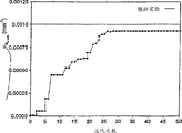
Fig. 8 and 9 is for utilizing the convergence curve figure of one embodiment of the present of invention difference analogue measurement fluorescent yield and fluorescence lifetime spatial variations.
Figure 10-14 is the image of gained in experimental example 1-3 of the present invention.
Figure 15 is the synoptic diagram of the system that constitutes according to a further embodiment of the invention.
The description of preferred embodiment
In order to promote understanding, referring now to embodiment shown in the accompanying drawing and utilize technical term that these embodiment are described to the principle of the invention.In any case but be to be understood that these descriptions are not limitation of the scope of the invention.The technician can accomplish in technical field of the present invention, any change of being done for the described device of the application and further improving, and all be predictable for the further application of the principle of the invention.
Fig. 1 represents that the present invention is used for organizing 100 systems 110 that carry out fluorescence imaging.The heterogeneous composition that tissue 100 has surface 101 and represents with the zone 102,103 under the surface 101.Heterogeneous composition 102,103 generally can't detect by the visual inspection to surface 101.
Detector 128,148 all is connected with heterodyne system subsystem 130 with light source 120.Subsystem 130 utilizes conventional laser device heterodyne technology to obtain the relevant light of being surveyed by detector 128 with respect to phase place, AC and DC intensity by the light of detector 148 detections.In one embodiment, heterodyne system subsystem 130 comprises and the phase locked signal synthesizer of laser pulse repetition frequency that is used as light source 120.In this embodiment, subsystem 130 comprises with the harmonic frequency with laser pulse repetition frequency (when using pulsed laser) or has said modulating frequency and adds the amplifier that the gain modulation detector 128,148 of a deviation (when using a modulated laser diode) links to each other, to produce required heterodyne.In the distortion of this embodiment, be 10 megahertzes with 80 megahertz pulsed laser skip keyings, be input in the said compositor, and the heterodyne of 100 KHz is input in the amplifier of detector 128,148.
Detector 128,148 is connected with processor 160.Processor 160 comprises input/control device 162, output unit 164 and storer 166.Processor 160 can be the electronic circuit that is made of one or more elements.Equally, processor 160 can by digital circuit, mimic channel or both be in conjunction with constituting.Processor 160 can also be programmable, integrated state machine, or aforementioned various structure is mixed formation.Preferably, input media 162 is input control devices of a keyboard or general type, and output unit 166 is one and is used for cathode ray tube (CRT), printer or other graphical presentation system well known to those skilled in the art that video shows.Electronics (for example solid-state), magnetic or optics one class storer that storer 166 preferably is used in combination with electronic controller or processor easily.In addition, storer 166 can comprise the combination of optical disc memory (CD), electromagnetism hard disk or floppy disk or above-mentioned storer.
Fig. 2 represents the program 210 of a kind of mode of operation of system 110.Program 210 comprises to be utilized processor 160 to measure fluorescent yields and the spatial variations in life-span and produces picture intelligence according to measurement result.Output unit 164 response diagram picture signals demonstrate an images.In tissue 100, inject a kind of fluorescent contrast agent in step 212 during program 210 beginnings.This contrast preparation has constituted the fluorescent radiation source of being surveyed by subsystem 240.The structure of modulated light source 120, heterodyne system subsystem 130 and detection subsystem 140 is designed to and to select exciting with radiation characteristic of fluorescent contrast agent suitable.In another embodiment, can also change or the interior living fluorophore of additional use, and corresponding Adjustment System 110.
In step 214, utilize light source 120 excite tissue 100 that constitute corresponding to selected fluorophore.In step 216, determine the radiation surveyed at each detecting location " i " phase theta with heterodyne (or deviation) frequency with respect to the exciting light of light source 120
Obs, and the logarithm M of AC intensity
ObsFor number is the detecting location of " Di ", and phase place of surveying or observing and AC intensity utilize index " i " to be designated (θ respectively
Obs)
i(M
Obs)
i Processor 160 is stored in these relative phases and AC strength information in the storer 166.
In step 218, set up a two-dimensional grid coordinate for a zone of the tissue 100 of selected imaging, set up a net point array, and identify with " j ".Specify consistent original value, i.e. fluorescent yield y at each net point j
j=(η μ
Ax → m)
jAnd fluorescence lifetime (τ)
jThese values all are the initial evenly estimated values to fluorescent yield value and fluorescence lifetime value, can change in these values step afterwards.Item " η " is a fluorescence quantum efficiency, and it changes along with the difference of fluorophore surrounding environment.Item " μ
Ax → m" be the absorption coefficient of fluorophore, it is the product of the natural logarithm value and the fluorophore concentration of fluorophore attenuation coefficient.Therefore, fluorescent yield y=η μ
Ax → mBe subjected to the influence of metabolin and fluorophore intake on every side.The intake of some known fluorophore is different and different according to main type of organizing and state, is of value to another fluorescent characteristic that detects disease thereby provide.Irrelevant substantially by contrast and fluorophore concentration that these characteristics produce.Initial estimate for fluorescent yield and life-span is stored in the storer 166 in order to using thereafter by processor 160.
Setting up fluorescent yield η μ
Ax → mAfter life-span τ characteristic initial estimate, enter in the cycle of treatment 220 in step 230.Preferably, utilize software, specialized hardware or both suitable combinations of programming in advance to carry out cycle of treatment step 220 by processor 160.In order to help the various mathematical operations in prehension program 210 and the circulation 220, below list selected argument table:
The c light velocity;
D (r) light-scattering coefficient;
Di detecting location numbering;
The f modulating frequency;
The I unit matrix;
I detecting location label;
J represent the sensitivity of each net point j and each detecting location response it
Between the Jacobi matrix of correlativity;
J net point label;
J
J, iEach matrix element in the Jacobi matrix J;
The k original label;
M modulation fluorescence is at the logarithm of the AC of a certain position intensity;
M modulating frequency overtones band
The n mean refractive index;
R position (bidimensional or three-dimensional);
The number of Sk modulated light source
S (r, ω) light modulated is in the source item of position r and frequencies omega;
Greek alphabet
χ
2The quality function of expression least square difference;
Ф
x(r ω) is illustrated in the plural number of the photon flux of position r and frequencies omega in the frequency field;
The quantum efficiency of η fluorescent tracing thing or dyestuff;
μ
aMean absorption coefficient;
μ
AmNon-fluorescent chromophore and fluorophore are to the absorption coefficient of fluorescence;
μ
AxNon-fluorescent chromophore and fluorophore are to the absorption coefficient of exciting light;
μ
Ax → cBecause the absorption coefficient that non-fluorescent chromophore produces;
μ
Ax → mFluorophore is to the absorption coefficient of exciting light;
μ '
sEffective scattering coefficient;
θ modulated light wave is with respect to alternative phase shift;
Tracer that τ is excited or dyestuff are in the life-span at position r place;
ω angle modulation frequency, the given 2 π f of unit;
Subscript
Obs observation or experimental data
The x exciting light;
M fluorescence or radiant light.
In step 230, go out the phase place of locating at each detecting location " i " and relative AC intensity as the function calculation of each the net point j place fluorescent yield and the initial estimate in life-span.Phase place and the intensity of each sensing point i that calculates are expressed as (θ respectively
m)
i(M
m)
iThese (θ
m)
i(M
m)
iValue is to utilize approximate the obtaining of diffuse scattering equation of radiation transfer equation.This diffuse scattering equation approximate description the room and time transport property of light in tissue or in multi-scattering media.Can be with a pair of frequency field diffuse scattering equation, promptly equation (1) and (2) are predicted exciting and emittance flow Ф of in the selected grid of tissue 100 r place, optional position respectively
x(r, ω) and Ф
m(r, ω):
The source item S of expression exciting light
x(r is owing to have the Sine Modulated light of angular frequency=2 ω f and form ω), and wherein f is generally in the frequency range of megahertz.The diffuse scattering of first expression light in diffuse scattering equation (1) and (2) or " random moving " transmission, wherein D
X, mBe the light diffuse scattering coefficient shown in following equation (3):
μ wherein
aAnd μ '
sBe respectively the absorption coefficient and the isotropy coefficient of tissue 100 and detection medium.These optical properties are relevant with optical wavelength, are different for the exciting light that sends from light source 120 (being designated as x down) with the fluorescent radiation of utilizing subsystem 140 to detect (being designated as m down) therefore.Total adsorption coefficient μ for the light of excitation wavelength
AxBe because non-fluorescent chromophore and fluorophore form corresponding to the contribution of excitation wavelength.Total adsorption coefficient is by the absorption coefficient μ of non-fluorescent chromophore
Ax → cWith fluorophore absorption coefficient μ
Ax → mAddition draws.Can suppose that generally the absorption for the light of wavelength of fluorescence mainly is because non-fluorescent chromophore produces.The light velocity in tissue is c
n=c/n, wherein n is a mean refractive index.The source item of fluorescent radiation and exciting light energy flow Ф
x(r, ω) relevant, by under establish an equation (4) provide:
This is to the time domain fourier transform at the fluorescence decay item of time domain after the exciting light incident pulse, and wherein τ is the fluorophore life-span, and η is a quantum efficiency, absorption coefficient μ
Ax → mBe the natural logarithm of the attenuation coefficient of the fluorophore that is in ground state and the product of concentration.As mentioned above, combination product η μ
Ax → mBe fluorescent yield y, it is proportional to the fluorescent energy flow that is produced.Equation (4) substitution equation (2) is convenient to obtain the Ф of each net point " j "
mDiffuse scattering equation (1) and (2) separating in the two dimensional area that is limited by net point " j " is easy to expand in the three dimensions, estimates one or more fluorescent characteristics spatial variations in the selection area of position " r " in corresponding to three dimensions.
Diffuse scattering equation (1) and (2) all are linear plural elliptic equations, can be with it as phasor Ф
x(r, ω) and Ф
m(r, boundary value problem ω) is found the solution.This finding the solution utilizes limited difference approach to set up corresponding limited difference equation.Utilize these difference equations to obtain approximate solution at each net point j.This method for solving is documented in other article of people such as Fulton, many grid methods of elliptic problem A Review, 114 American Meteorological Society pp.934-59 (May, 1986); The initial assessment of the single system of using with people's such as B.W.Pogue article frequency domain diffuse scattering optics tomographic, 40 Physics in Medicine and Biology pp.1709-1729 (1995).A kind of preferred method for solving is to utilize at Adams the article MUDPACK of J.C.: carry out for the oval partial differential equation of linearity provides the MUDPACK program described in the portable Fortran software 34 App.Math Comp.p.133 (1989) of many grids of effectively separating.In order to find the solution this diffuse scattering equation, suppose Ф on the surface 101 of tissue 100
m(r, ω)=0, this hypothesis is called zero energy flow boundary condition.Will be appreciated that the boundary condition that to select other, thereby method for solving is also different.
The plural number that can solve each net point j from diffuse scattering equation (1) and (2) is separated Ф
mThe detectable signal on surface is proportional to the normal state component of photon energy flow gradients.Be positioned at detector position " i " gained signal on tissue 100 surfaces 101 in order to approach, the Ф that just is proportional at inner side surface 101 according to the normal state component of photon energy flow gradients
mRelation, select Ф near the interior net point place of this position
mValue.From plural Ф
mImaginary part and real part calculate detecting location " Di " and locate phase delay θ with respect to the phase place and the AC intensity of light source 120
mWith AC intensity logarithm M
m
Diffuse scattering equation (1) and (2) make the people understand the fluorescent optics characteristic of tissue 100 in depth for the θ that records at detector position i
mAnd M
mSensitivity.By the various parameters in fixedly diffuse scattering equation (1) and (2) and carry out series of computation and can obtain these results.These calculating have supposed that circle organizes analogue body 300, wherein are concealed with the heterogeneous thing 302 of embedding in analogue body background 303, as shown in Figure 3.Set up a two-dimensional grid for analogue body 300, this grid can expand to three-dimensional at an easy rate.Under these simulated conditions, the have a few of giving the simulated tissue external body has bigger absorption coefficient value to exciting light and fluorescence.Four source S1-S4 (Sk=4) shown in Figure 3 simulate by giving at any plural number of a net point near the near surface in each source.20 detecting location D1-D20 (Di=20) shown in Figure 3 utilize near the Ф of the net point " j " of detecting location
mThe calculated value of obtaining is simulated.Analog solution for equation (1) and (2) is to obtain for one 65 * 65 two-dimensional grid, said grid covers the circle of one 100 mm dia and organizes analogue body 300, comprises 30 millimeters of diameters in organizing analogue body, is positioned at and organizes the circle at analogue body 300 centers (this position is somewhat different than the position of heterogeneous thing shown in Figure 3) to embed heterogeneous thing.For 20 equidistant detecting location D1-D20, obtain the analogue measurement result of fluorescence phase shift and AC intensity around setting.Modulating frequency f is set at 150 megahertzes.The optical property of heterogeneous thing and background is illustrated in down in the tabulation 1:
Table 1
In order to estimate η μ
Ax → mInfluence, the η μ in heterogeneous thing
Ax → mFrom 10
-4Mm
-1Increase to 10
-1Mm
-1And the η μ in the background 303
Ax → mWhen keeping constant, value calculates the θ at each sensing point D1-D20 place
mAnd M
mFor because η μ
Ax → mDifference and produce the object and the background of contrast, fluorescence lifetime τ is set at 1 nanosecond.θ with respect to an effective source Sl
mAnd M
mCurve map is illustrated respectively among Fig. 4 and Fig. 5.As the η of heterogeneous thing 102 μ
Ax → mWhen value was increased to higher value, AC intensity leveled off to a upper limit, in the non-diffusion of dilution is separated, estimated similar.Fig. 5 represents as fluorophore absorption coefficient μ
Ax → mWhen reducing 10 to 100 times of background material absorption coefficient, the fluorescence phase shift theta
mHow to reduce.According to these analog results, M as can be known
mAs if with the η μ that organizes heterogeneous thing 102 that simulates
Ax → mVariation directly related, wherein θ directly depends on because the η μ that photon transport change to produce
Ax → m
In order to estimate the influence of τ, the τ value in heterogeneous thing is 10
-1Nanosecond is to 10
3Change between the nanosecond and τ value in the background is calculated the θ at each sensing point D1-D20 place when remaining on 1 nanosecond
mAnd M
mBackground η μ
Ax → mBe set at 10
-5Mm
-1, and the η μ of heterogeneous thing
Ax → mBe set at 10
-3Mm
-1As shown in Figure 6, the AC intensity of surveying when the τ value reduces increases.Fig. 7 represents the fluorescence phase-shift value that records at each sensing point when the fluorescence lifetime in the heterogeneous thing when changing for 0.1 nanosecond between 1000 nanoseconds.At (in this calculates is 150 hertz) under the given modulating frequency, θ
mAt first increase, reach a maximal value, when 0.1 nanosecond increases to 1000 nanoseconds, reduce continuously again as τ then.So, can think the θ at each sensing point D1-D20 place
mAnd M
mDirectly related with fluorescence lifetime value in the heterogeneous thing.
Refer again to Fig. 2, in step 240, with radiation phase place and the intensity (θ that calculates
m)
i(M
m)
iWith the radiation phase place and the intensity (θ that measure at each sensing point " i "
Obs)
i(M
Obs)
iRelatively to determine difference or " error " between measured value and the calculated value.Because (η μ
Ax → m)
jInfluence (M
m)
iSo this relatively is quality function χ with equation as follows (5)
μ 2Form carry out:
σ wherein
MBe M
mIn typical noise bias, be taken as 0.01; The Sk=excitaton source is counted out, and is designated as k down; Di=sensing point number is designated as i down.The purpose of this algorithm is by suitable renewal (η μ
Ax → m)
jAnd make χ
μ 2Reach minimum value.At first (the η μ that upgrades
Ax → m)
jAfterwards, about (τ)
jAnother quality function participate in the comparison of step 240.This quality function χ
τ 2Equation shown in being expressed as (6)
σ wherein
0Be (θ
m)
iIn typical noise bias, be taken as 1 degree; The Sk=excitaton source is counted out, and is designated as k down; Di=sensing point number is designated as i down.Because the life-span is for (θ
m)
i(M
m)
iAll influential, in equation (6), used phase place and AC intensity level.
By calculating quality function χ
μ 2, χ
τ 2And carried out after the comparison in the step 240, control program entry condition determining step 250 is judged measured value (θ
Obs)
i(M
Obs)
iWith calculated value (θ
m)
i(M
m)
iBetween whether satisfy selected convergence criterion by means of the comparative result of quality function gained.Franchise degree when this criterion is equivalent to determine fluorescent yield and life value.In one embodiment, as following three values (i) χ
2, (ii) χ in continuous iterative loop 220
2Variation, (ii) χ in continuous iterative loop 220
2Relative variation in any one less than one 1.0 * 10
-2Threshold value the time reach convergence.In other embodiments, as is known to the person skilled in the art, can adopt different comparison computing method and condition judgment standard.If condition judgment 250 is met, control program enters step 270, withdraws from circulation 220; But,, continue to carry out circulation 220 in step 260 if do not satisfy this criterion.
In step 260, upgrade the fluorescent yield (y) of each net point j
j=(η μ
Ax → m)
jAnd the life-span (τ)
jThereby, make these values can reach minimum deflection corresponding to comparison step 240 and condition judgment step 250.In order to upgrade these values, can use the Jacobi matrix, this matrix representation is in the response of each sensing point i fluorescent yield (y) for each net point j
j=(η μ
Ax → m)
jAnd the sensitivity of the variation of life-span (τ) j.Adopt three Jacobi matrixes:
 With
With
 The matrix element J of these Jacobi matrixes
I, jRespectively by [ Mi/ ( (η μ
Ax → m)
j]; J
I, j=[ Mi/ τ
j]; And J
I, j=[ Q/ τ
j] provide.By each net point j being found the solution diffuse scattering equation (1) and (2) four times, utilize (τ)
j(τ+δ τ)
j, and (η μ
Ax → m)
j(η μ
Ax → m+ δ η μ
Ax → m)
jCalculate M
M, iAnd θ
M, i, can be in the hope of these matrix elements.According to the least square method of minimizing, calculate the updating value in fluorescent yield and life-span.In a preferred embodiment, this update algorithm is selected from and is used for a kind of algorithm that reconstruct utilizes the image that the electrical impedance tomographic obtained, as the algorithm of people such as Yorkey proposition in " electrical impedance tomographic with the comparison of restructing algorithm " (34 Transactions in Biomedical Engineering pp.843-52 (1987)).These Jacobi matrixes are used to find the solution renewal vector [Δ η μ
Ax → m] and [Δ τ], to estimate yield vector [η μ respectively
Ax → m] and life-span vector [τ].The dimension of these vectors is corresponding to the number of net point.In each iterative loop 220, find the solution following Jacobi matrix (7) and (8) to determine the updating value of yield and life-span vector estimated value:
The matrix element J of these Jacobi matrixes
I, jRespectively by [ Mi/ ( (η μ
Ax → m)
j]; J
I, j=[ Mi/ τ
j]; And J
I, j=[ Q/ τ
j] provide.By each net point j being found the solution diffuse scattering equation (1) and (2) four times, utilize (τ)
j(τ+δ τ)
j, and (η μ
Ax → m)
j(η μ
Ax → m+ δ η μ
Ax → m)
jCalculate M
M, iAnd θ
M, i, can be in the hope of these matrix elements.According to the least square method of minimizing, calculate the updating value in fluorescent yield and life-span.In a preferred embodiment, this update algorithm is selected from and is used for a kind of algorithm that reconstruct utilizes the image that the electrical impedance tomographic obtained, as the algorithm of people such as Yorkey proposition in " electrical impedance tomographic with the comparison of restructing algorithm " (34 Transactions in Biomedical Engineering pp.843-52 (1987)).These Jacobi matrixes are used to find the solution renewal vector [Δ η μ
Ax → m] and [Δ τ], to estimate yield vector [η μ respectively
Ax → m] and life-span vector [τ].The dimension of these vectors is corresponding to the number of net point.In each iterative loop 220, find the solution following Jacobi matrix (7) and (8) to determine the updating value of yield and life-span vector estimated value:
Mm
ObsBe respectively measurement vector value and compute vectors value with Mm at the AC intensity logarithm at each sensing point i place.θ m
ObsBe respectively measurement vector value and compute vectors value with θ m in the phase lag at each sensing point i place.Because the ill characteristic of Jacobi matrix has increased λ
1I or λ
2The I item minimizes the part of scheme as the horse quart, and wherein I is a unit matrix.Parameter lambda
1Or λ
2Utilization is write in " numerical method: science calculate means " (Cambridge UniversityPress, 1992) literary composition disclosed the sort of Maquardt-Levenberg type algorithm and is adjusted people such as Press.Each linear algebraic equation that generates simultaneously from Jacobi matrix equation (7) and (8) adopts conventional numerical method to find the solution.In each iterative loop 220, recomputate the Jacobi matrix.Have been found that equation (7) and (8) provide a kind of mode of selecting the suitable changing value of yield and life estimate value; But other numerical method that obtains gratifying estimated value by recursive iteration well known to those skilled in the art also is admissible.In a single day refresh routine is finished, and then control program turns back to step 230.
If convergence criterion is met in condition judgment step 250, illustrate that then the fluorescent yield of each net point and life estimate value reach gratifying minimum value, control program returns step 270.At the spatial variations generation picture intelligence of step 270 processor 160 according to yield and/or life-span fluorescent characteristic.This picture intelligence is sent to output unit 164, and it responds this signal and demonstrates an images.Because these fluorescent characteristics of yield and life-span are generally with bioenvironmental different variation the around the fluorophore, therefore this image is often referred to illustrate and organizes mutation, can detect heteroplasmon 102,103 thus.For example, laser diode can send near infrared light (NIR), and it is dark that this near infrared light can penetrate several centimetres of tissues, can use the imaging system that the fluorescent contrast agent of near infrared light sensitivity is constituted a practicality.In one embodiment, this system applies an endoscope.
Except yield with the life-span, other helps to discern the spatial variations of the fluorescent characteristic that diseased tissues is arranged can also to utilize diffuse scattering equation (1) and (2) conversion.Other fluorescent characteristic of this class includes but are not limited to, as the quantum efficiency η and/or the fluorescent absorption coefficient μ of the autonomous behavior that does not rely on fluorescent yield
Ax → m
In another embodiment of the present invention, utilize photon energy flow equation and Jacobi evaluation method to determine to specify fluorophore to take in the transformation relation of concentration.In this embodiment, do not using under the situation of specifying fluorophore by estimating the non-fluorescent chromophore adsorption coefficient μ of each net point j
Ax → cWith scattering coefficient μ '
s, rather than yield and definite scattering coefficient μ ' of life-span
sWith chromophore adsorption coefficient μ
Ax → cWith first transformation relation.Can be with about Ф
x(r, diffusion equation ω) (1) are used in combination with improved Jacobi equation (7) and (8) and set up this first transformation relation.This improvement uses chromophore adsorption coefficient and scattering coefficient to replace fluorescent yield, and after the adjustment, these new characteristics establish an equation under satisfying:
With
The matrix element of used four Jacobi matrixes
With
 Respectively by
 With
Provide.Upgrade these absorption coefficients and scattering coefficient transformation relation so that quality function χ
2Minimize:
With
Provide.Upgrade these absorption coefficients and scattering coefficient transformation relation so that quality function χ
2Minimize:
N wherein
s=Sk, n
d=Di.
After producing first transformation relation, apply the fluorescent contrast agent of appointment, and replace μ
Ax → cWith μ
AxTotal adsorption coefficient μ is determined in substitution equation (9)-(11)
Ax, to obtain second transformation relation of total adsorption coefficient.Should point out μ
Ax=μ
Ax → m+ μ
Ax → x, the intake of fluorescent contrast agent is proportional to μ
Ax → m, taking in concentration can be by determining that the difference between the adsorption coefficient variable quantity converts out in first and second transformation relations.Can utilize the images of this " difference conversion " generation then corresponding to intake concentration.
Another examples measure responds the radiation of each modulation of source frequency f.The sum of employed different frequency is defined as Mf.In order to obtain this additional data, carry out iterative loop 220 for each frequency f that is designated as m down.Number of light sources Sk and sensing point Di make subscript with k and i respectively.This additional data can be used to improve the image effect that utilizes system 110 to obtain, and perhaps can reduce the sensing point number or the excitation source number that use in estimation.Corresponding to a feature quality function of this additional data by under establish an equation (12) provide: χ τ
2=
Except fluorescent yield and life-span method, can also use other interested optical characteristics of multifrequency method conversion.Except the Sine Modulated light source, the present invention in other embodiments can also apply pulse or other the time become excitation source.
Figure 15 represents an optical system 410 adopting in another embodiment of the present invention.This system comprises modulated light source 420, and this light source comprises laser driver 422 and the reference frequency generator 426 that links to each other with laser diode 424.Light source 420 is used for light modulated is transferred to organizer 400, will focus on from the light that organizer gives off again the gain modulation image intensifier 430 by 50 millimeters lens 432 then.Booster 430 comprises that one is the time pole-face of electronics with photon conversion, a MicroChannel Plate (MCP), and it makes electronic signal multiplication and a phosphorescent screen by the avalanche multiplication effect, and it is an optical image with electronic switch.Preferably, the quick booster that booster 430 is produced for Litton electronics, inc., it can be by applying a Dc bias and modulating from a RF signal of amplifier 428 between photocathode and MicroChannel Plate.In this example, for the modulation from the image of booster 430 be utilize from one the 10 megahertz signal and the laser diode 424 of compositor 426 outputs phase locked.By laser diode 424 and image intensifier 430 being modulated, can on phosphorescent screen, generate the stable state image according to identical frequency.Authorize in people's such as Gratton the U.S. Pat-5213105 some background content relevant with this technology are provided.The image that generates at phosphorescent screen focuses in a beam coupling device (CCD) video camera 434 through 150 millimeters pack-shot lens 436 and by interference light filter 433.Video camera 434 has one 512 * 512 ccd detector array, to form corresponding pixelation image.Video camera 434 links to each other with the processor 460 with above-mentioned processor 160 analog structures.
After obtaining image,, between image intensifier 430 and laser diode 424, produce phase delay by utilizing frequency synthesizer 452 to make phase place stepping between 0 to 360 degree of image intensifier 430 under the control of processor 460 at every turn.Because the gain modulation of image intensifier 430 and laser diode 424 is carried out according to same frequency, homodyneization makes and produce a width of cloth stable state phosphorescence image on the booster 430 that depends on phase place.Preferably, utilize conventional gpib interface realization compositor 452 and the control between the processor 460.Then the image on the phosphorescent screen of image intensifier 430 is superimposed with each phase delay.The phase delay image that utilize to increase then produces exciting light and organizer 400 transformation relation of phase shift and intensity modulated ratio between the radiant light again.By applying the light filter of interfering or being fit to, can selectively radiant light be separated with exciting light and measure.The output of video camera 434 can utilize program 210 to handle by processor 460.
1-3 further describes the present invention below with reference to instantiation.Be appreciated that these examples are illustrative, rather than restrictive.Example 1-3 comprises the computer simulation to program 210.This simulation comprises the simulation of tissue, to those skilled in the art, is a kind of effective means of demonstration fluorescence spectrum image characteristics.These example utilizations under tabulate and find the solution about θ under the condition shown in 2
mAnd M
mDiffusion equation (1) and (2) analogue value of being obtained:
Table 2
These example simulation organizers 300 with 100 mm dias shown in Figure 3.Calculate at each sensing point D1-D20 shown in Figure 3 corresponding to the θ that is positioned at its four modulated light source S1-S4 on every side
mAnd M
mValue.Exciting light modulating frequency f is modeled as 150 megahertzes.Find the solution the various combination (Sks of diffusion equation (1) and (2) acquisition corresponding to sensing point and light source position
*80 groups of θ of Di=4 * 20=80)
mAnd M
mThe analogue value.Separate middle θ at diffusion equation
mLast stack 0.1 degree (or being loosened to 1 degree), M
mThe standard deviation Gaussian noise of last stack 1%.On a SunSpare10 computing machine, utilize MUDPACK program solution diffusion equation (1) and (2) that adapt to.Utilize the data set the obtained analog input value of program 210 among the 1-3 as an example.The result is illustrated in the following table 3 and table 4:
Table 3
Table 4
| Embodiment | Area, target 1 (mm 2) | The position, target 1 (x, y), (mm, mm) | Area, target 2 (mm 2) | The position, target 2 (x, y), (mm, mm) |
| 5.1 | (706.0 expectation value) 742.2 (measured value) | (60,60) (expectation value) (60.8,58.5) (measured value) | Do not use | Do not use |
| 5.2 | (706.0 expectation value) 703.1 (measured value) | (60,60) (expectation value) (59.4,58.3) (measured value) | Do not use | Do not use |
| 5.3 | (314.1 expectation value) 381.0 (measured value) | (32.3,67.7) (expectation value) (34.0,67.7) (measured value) | (314.1 expectation value) 342.0 (measured value) | (67.7,32.3) (expectation value) (65.0,35.0) (measured value) |
| Embodiment | ????ημ ax→m(target) (mm -1) | τ (target) (ns) |
| ????5.1 | ????1.0×10 -3(expectation value) 0.93 * 10 -3(measured value) | (1.0 expectation value) 1.03 (measured value) |
| ????5.2 | ????1.0×10 -3(expectation value) 0.8 * 10 -3(measured value) | (1.0 expectation value) 0.7 (measured value) |
| ????5.3 | (upper left-hand target) 1.0 * 10 -3(expectation value) 2 * 10 -3(measured value) (lower right sidelong glance mark) 2.0 * 10 -3(expectation value) 1.8 * 10 -3(measured value) | (upper left-hand target) 1.0 (expectation values) 4.1 (measured value) (lower right sidelong glance mark) 2.0 (expectation values) 3.5 (measured value) |
Example 1
Example 1 is reconstruct fluorescent yield and life-span under the absorbing state that does not have non-fluorescent chromophore to produce.In this example for the simulated experiment data, corresponding to fluorescent yield (the η μ of background and heterogeneous composition 302
Ax → m)
jBe chosen to be 1 * 10 respectively
-5Mm
-1With 1 * 10
-3Mm
-1, be chosen to be 10 nanoseconds and 1 nanosecond respectively corresponding to fluorescence lifetime (τ) j of background and heterogeneous composition 302.In carrying out circulation 220 processes, do not presuppose the position and the background fluorescence characteristic of heterogeneous composition 302, but provide consistent assumed value, i.e. fluorescent yield (η μ respectively
Ax → m)
jBe 1 * 10
-5Mm
-1, the life-span (τ)
jIt is 10 nanoseconds.For bidimensional 17 * 17 grids, be less than 50 iterative loop 220 and promptly realize convergence result's (be 2 hours the computing time on the SunSparc10 computing machine).Fig. 8 and Fig. 9 are illustrated respectively in the η μ of simulated target place net point
Ax → mIn 50 iteration, converge to η μ with the mean value of τ
Ax → m=0.93 * 10
-3Mm
-1And τ=1.03 nanosecond.Figure 10 and Figure 11 represent the μ according to η respectively
Ax → mWith the image of the transformed value reconstruct of τ, and represent desired image.In example 1-3, remove and have unreasonable high value by interpolation method, but but be in zone of reasonableness the value encirclement vacation point and make image smooth.These false point values are used in the fluorescent yield of acquisition in the simulation loop 220 and the average background values in life-span replaces.
The η μ of the net point on the simulation background
Ax → mMean value converges to 9 * 10 in 50 iteration
-5Mm
-1The τ value of background converges to 5.4 nanoseconds.Final gained image passes through respectively to (η μ for the correlativity of initial assumed value
Ax → m)
j(τ)
jProvide 1 * 10
-4Mm
-1Check with assumed value with 10 nanoseconds prima facies.Consequently acquisition and Figure 10 and similar image shown in Figure 11.
By all η μ
Ax → mValue is greater than η μ
Ax → → mThe part that the net point of 35% (selected arbitrarily) of peak value constitutes is identified as heterogeneous composition 302 positions (shown in Figure 10).All are identified as the coordinate mid point of net point of target in the position (60.8,58.5), and this point is near the location point (60,60) that is used for the simulated experiment data.Listed as table 3, according to our any criterion of identification of definition, the area of heterogeneous composition is 72 square millimeters, near the numerical value of the simulated experiment data that are used to produce us.
Example 2
Example 2 is reconstruct fluorescent yield and life-span under the situation of utilizing simulation chromophore absorption simulated human tissue.Except supposition has uniform background chromophore absorption coefficient η μ
Ax →=1 * 10
-3Mm
-1In addition, adopt with in hiding heterogeneous composition identical described in the example 1 and optical parametric and analog machine generation simulated experiment data.Though exciting light also is not used in image reconstruction, we suppose known this optical characteristics, and oppositely the best of reconstructed image may characteristic under physiological condition to estimate.Figure 12 and Figure 13 represent fluorescent yield (η μ respectively
Ax → m)
j(τ)
jThe conversion of bidimensional reconstruction attractor.As shown in table 3, according to us based on η μ
Ax → mCriterion, the mean value of target location is (59.4,58.3), with the term harmonization that is used for the simulated experiment data.Criterion of identification (all η μ according to our any definition
Ax → mValue is greater than peaked 35% net point), the area of heterogeneous composition is 703 square millimeters, this value is near the numerical value of the simulated experiment data that are used to produce us.The η μ of the net point in simulated target zone
Ax → mIn 50 iteration, converge to η μ with τ mean value
Ax → m=0.8 * 10
-3Mm
-1And τ=0.7 nanosecond, they and the value consistent (seeing Table 3) that is used to produce the simulated experiment data.The η μ of the net point in simulation background zone
Ax → mWith the mean value of τ in 50 iteration, converge to example 1 in the close value of report value.
Example 3
Example 3 simulations have two situations (not shown in Fig. 3) of hiding heterogeneous composition in organizer.In this case, except will be corresponding to the fluorescent yield η μ of target 1 and target 2
Ax → mBe chosen to be 1 * 10 respectively
-3Mm
-1With 2 * 10
-3Mm
-1, will be chosen to be respectively corresponding to the fluorescence lifetime τ of target 1 and target 2 outside 1 nanosecond and 2 nanoseconds, other used parameter is with identical described in the example 1.Replaced 17 * 17 grid with one 33 * 33 grid.In Figure 14, represented and the corresponding images of fluorescent yield conversion.
Publication that all are quoted in this manual and patented claim all in the mode of reference in conjunction with in this application, as all pointing out separately and particularly with reference pattern in conjunction with in this application for each part publication or patented claim.Although at length explained the present invention in the accompanying drawings with in the top description; but these contents are illustrative; rather than restrictive, should be understood to it and just represent and described preferred embodiment, all changes in the present invention conceives scope and improving all need protection.
Claims (26)
1, a kind of image formation method, it may further comprise the steps:
(a) surface of a kind of light-scattering material of excitation light irradiation that sends with a light source comprises a kind of heterogeneous composition under the surface of said material;
(b) survey said substance responds step (a) and the fluorescent radiation sent;
(c) provide the spatial variations estimated value of the fluorescent characteristic of this material;
(d) definite calculating radiation as said estimated value function;
(e) will compare to determine error with the calculating radiation in the radiation that step (b) is surveyed;
(f) provide the estimated value that improves of said fluorescent characteristic spatial variations, and repeating step (d) reaches required minimum value to (f) up to said error; With
(g) produce an images according to the estimated value that improves, this image is corresponding to the heterogeneous composition in the said material.
2, method according to claim 1, it also is included in the step that applies fluorescent contrast agent in the said material.
3, method according to claim 1 is characterized in that step (f) comprises to use the Jacobi matrix.
4, method according to claim 1 is characterized in that desired radiation is to obtain as the function of a diffusion equation.
5, method according to claim 1, it is characterized in that step (e) comprise the intensity that will calculate radiation and phase place with in the intensity of the radiation of step (b) detection and the step of bit comparison mutually.
6, method according to claim 1 is characterized in that comprising in the said material a kind of fluorescent contrast agent, and said fluorescent characteristic is an at least a function in fluorescence quantum efficiency, fluorescence lifetime and the fluoroscopic visualization agent concentration.
7, as method as described in the claim 6, it is characterized in that said fluorescent characteristic is the function of fluorescence quantum efficiency, said light source is the light source that carries out intensity modulated with preset frequency, step (e) comprise the AC intensity that will calculate radiation and phase place with in the intensity of the radiation of step (b) detection and the step of bit comparison mutually, step (f) comprises the step of using the Jacobi operator, and desired radiation is to obtain as the function of photon energy flow in the tissue.
8, a kind of image formation method, it may further comprise the steps:
(a) the excitation light irradiation vivo biological tissue that sends with a light source;
(b) survey the fluorescent radiation that the said irradiation of said tissue response is sent;
(c) determine in the said tissue spatial variations with a processor as the fluorescent characteristic of said radiation function; With
(d) generate an images of said tissue according to said spatial variations.
9, as method as described in the claim 8, it is characterized in that it also is included in the step that applies a kind of fluorophore in the said tissue.
10, as method as described in the claim 8, it is characterized in that said fluorescent characteristic is a function at least a in fluorescence lifetime, fluorescence quantum efficiency or the fluorescent absorption.
11,, it is characterized in that said irradiating step comprises said light source is positioned near the said tissue surface step that said detection steps comprises the step of detection at the light of said surface emissivity as method as described in the claim 9.
12, as method as described in the claim 8, it is characterized in that said irradiating step comprise will contiguous said tissue surface one group of modulated light source localization step, said detection steps comprises the step of detection light of one group of position radiation on said surface.
13, as method as described in the claim 8, it is characterized in that said determining step may further comprise the steps: the estimated value that (i) provides the spatial variations of said fluorescent characteristic, (ii) determine to calculate radiation value as the function of said estimated value, (iii) radiation value that calculates and the fluorescent radiation value that obtains in said detection steps are compared to determine error, (iv) provide said fluorescent characteristic spatial variations improve estimated value, (v) the estimated value that improves is repeated said determining step and said comparison step, reach required minimum value up to said error.
14, a kind of image formation method, it may further comprise the steps:
(a) in containing the light scattering biological tissue of heterogeneous composition, add a kind of fluorescent contrast agent;
(b) the said tissue surface of rayed that sends with a light source is to excite said contrast preparation;
(c) survey the radiant light that the said irradiation of said tissue response is sent;
(d) determine the class value of expression as the fluorescent characteristic of position and radiation function; With
(e) produce an images according to these values, this image is corresponding to the heterogeneous composition in the said tissue.
15, as method as described in the claim 14, it is characterized in that said fluorescent characteristic is the function of fluorescence quantum efficiency.
16, as method as described in the claim 14, it is characterized in that said fluorescent characteristic is corresponding to fluorescence lifetime.
17,, it is characterized in that said detection steps is included on the said surface that one group of position sensing responds said irradiating step and the fluorescence that sends as method as described in the claim 14.
18,, it is characterized in that said irradiating step comprises from along luminous step the one group of light source placed apart of surface as method as described in the claim 14.
19,, it is characterized in that said irradiating step comprises with the light modulated with one group of different frequency to excite fluorescent contrast agent in said tissue, and determine radiation value as the function of different frequency as method as described in the claim 14.
20, as method as described in the claim 14, it is characterized in that said determining step may further comprise the steps: (i) provide estimated value, (ii) determine calculating radiation value as said estimated value function, the radiation that (iii) will calculate radiation and described detection compares to determine error, (iv) provide the estimated value of improvement, (v) repeat said determining step and said comparison step, reach required minimum value up to said error for the estimated value that improves.
21, be used for the light scattering that comprises a kind of heterogeneous composition and a kind of fluorophore is organized a kind of system of imaging, it comprises:
(a) be applicable to a light source that excites said fluorophore;
(b) detector, it is used to produce and is equivalent to the light that said tissue response sends from said light source and the detection light signal of the fluorescent radiation of sending;
(c) processor, it links to each other with said detector operation, and respond said detection light signal generating and represent in the said tissue a class value as the fluorescent characteristic of function of position, said fluorescent characteristic is equivalent in fluorescence lifetime, fluorescence quantum efficiency and the fluorescent absorption at least a, and said processor is used to produce the picture intelligence as the function of said value; With
(d) output unit, it responds the images of said picture intelligence generation corresponding to heterogeneous composition in the said tissue.
22, as system as described in the claim 21, it also comprises one group of modulated light source.
23, as system as described in the claim 21, it is characterized in that said fluorescent characteristic is equivalent to fluorescent yield.
24, as system as described in the claim 21, it is characterized in that said detector is used for one group of said radiation of position sensing on said tissue surface.
25, as system as described in the claim 21, it is characterized in that said processor is used for determining said value according to calculating radiation with the comparative result of the measuring radiation that obtains from said detection light signal, said calculating radiation is to determine as the function of the spatial variations estimated value of said fluorescent characteristic, upgrade said estimation changing value, and repeating said comparison, the difference between said calculating radiation and said measuring radiation reaches required minimum value.
26, as system as described in the claim 21, it is characterized in that said light source comprises a laser diode, said detector comprises a ccd video camera.
Applications Claiming Priority (2)
| Application Number | Priority Date | Filing Date | Title |
|---|---|---|---|
| US274695P | 1995-08-24 | 1995-08-24 | |
| US60/002,746 | 1995-08-24 |
Publications (1)
| Publication Number | Publication Date |
|---|---|
| CN1200174A true CN1200174A (en) | 1998-11-25 |
Family
ID=21702295
Family Applications (1)
| Application Number | Title | Priority Date | Filing Date |
|---|---|---|---|
| CN96197632A Pending CN1200174A (en) | 1995-08-24 | 1996-08-23 | Fluorescence lifetime-based imaging and spectroscopy in tissues and other random media |
Country Status (9)
| Country | Link |
|---|---|
| US (1) | US5865754A (en) |
| EP (1) | EP0846262A4 (en) |
| JP (1) | JP3819032B2 (en) |
| CN (1) | CN1200174A (en) |
| AU (1) | AU1130797A (en) |
| CA (1) | CA2230228C (en) |
| MX (1) | MX9801351A (en) |
| NO (1) | NO980750L (en) |
| WO (1) | WO1997008538A1 (en) |
Cited By (20)
| Publication number | Priority date | Publication date | Assignee | Title |
|---|---|---|---|---|
| US6915154B1 (en) | 1999-09-24 | 2005-07-05 | National Research Council Of Canada | Method and apparatus for performing intra-operative angiography |
| US7881777B2 (en) | 1999-09-24 | 2011-02-01 | National Research Council Of Canada | Method and apparatus for performing intra-operative angiography |
| CN101975769A (en) * | 2010-09-17 | 2011-02-16 | 福建师范大学 | Human tissue autofluorescence detection system based on excitation of light sources with different wavelength |
| CN101980656A (en) * | 2008-03-27 | 2011-02-23 | 皇家飞利浦电子股份有限公司 | Method for reconstructing a fluorescent image of the interior of a turbid medium and device for imaging the interior of a turbid medium |
| CN101194270B (en) * | 2003-04-04 | 2012-07-11 | 光谱辨识公司 | Multispectral biometric sensor |
| CN103364326A (en) * | 2002-07-31 | 2013-10-23 | 阿尔利克斯公司 | System and method of sorting materials using holographic laser steering |
| CN103917859A (en) * | 2011-11-16 | 2014-07-09 | 索尼公司 | Biometric device, biometric method, program, and recording medium |
| US9421280B2 (en) | 2005-04-26 | 2016-08-23 | Novadaq Technologies Inc. | Real time imaging during solid organ transplant |
| US9610021B2 (en) | 2008-01-25 | 2017-04-04 | Novadaq Technologies Inc. | Method for evaluating blush in myocardial tissue |
| US9816930B2 (en) | 2014-09-29 | 2017-11-14 | Novadaq Technologies Inc. | Imaging a target fluorophore in a biological material in the presence of autofluorescence |
| CN107850531A (en) * | 2015-05-28 | 2018-03-27 | 捷普有限公司 | Systems, devices and methods for the jointing material inspection of distribution |
| US10041042B2 (en) | 2008-05-02 | 2018-08-07 | Novadaq Technologies ULC | Methods for production and use of substance-loaded erythrocytes (S-IEs) for observation and treatment of microvascular hemodynamics |
| US10219742B2 (en) | 2008-04-14 | 2019-03-05 | Novadaq Technologies ULC | Locating and analyzing perforator flaps for plastic and reconstructive surgery |
| US10265419B2 (en) | 2005-09-02 | 2019-04-23 | Novadaq Technologies ULC | Intraoperative determination of nerve location |
| US10278585B2 (en) | 2012-06-21 | 2019-05-07 | Novadaq Technologies ULC | Quantification and analysis of angiography and perfusion |
| US10434190B2 (en) | 2006-09-07 | 2019-10-08 | Novadaq Technologies ULC | Pre-and-intra-operative localization of penile sentinel nodes |
| US10492671B2 (en) | 2009-05-08 | 2019-12-03 | Novadaq Technologies ULC | Near infra red fluorescence imaging for visualization of blood vessels during endoscopic harvest |
| US10631746B2 (en) | 2014-10-09 | 2020-04-28 | Novadaq Technologies ULC | Quantification of absolute blood flow in tissue using fluorescence-mediated photoplethysmography |
| CN112449683A (en) * | 2018-04-26 | 2021-03-05 | 达特默斯大学托管会 | Apparatus and method for determining depth and concentration of fluorescent objects under surface |
| US10992848B2 (en) | 2017-02-10 | 2021-04-27 | Novadaq Technologies ULC | Open-field handheld fluorescence imaging systems and methods |
Families Citing this family (245)
| Publication number | Priority date | Publication date | Assignee | Title |
|---|---|---|---|---|
| US5353799A (en) * | 1991-01-22 | 1994-10-11 | Non Invasive Technology, Inc. | Examination of subjects using photon migration with high directionality techniques |
| US6304771B1 (en) * | 1993-10-29 | 2001-10-16 | The Trustees Of The University Of Pennsylvania | Systems and methods for imaging fluorophores |
| US5919140A (en) * | 1995-02-21 | 1999-07-06 | Massachusetts Institute Of Technology | Optical imaging using time gated scattered light |
| US7328059B2 (en) * | 1996-08-23 | 2008-02-05 | The Texas A & M University System | Imaging of light scattering tissues with fluorescent contrast agents |
| US6766183B2 (en) | 1995-11-22 | 2004-07-20 | Medtronic Minimed, Inc. | Long wave fluorophore sensor compounds and other fluorescent sensor compounds in polymers |
| US6571119B2 (en) | 1996-03-06 | 2003-05-27 | Fuji Photo Film Co., Ltd. | Fluorescence detecting apparatus |
| JP3796635B2 (en) * | 1996-03-06 | 2006-07-12 | 富士写真フイルム株式会社 | Fluorescence detection device |
| US6525862B2 (en) * | 1996-10-30 | 2003-02-25 | Photogen, Inc. | Methods and apparatus for optical imaging |
| EP0983501A4 (en) | 1996-11-08 | 2000-03-08 | Purdue Research Foundation | Particle analysis system and method |
| US5952664A (en) * | 1997-01-17 | 1999-09-14 | Imaging Diagnostic Systems, Inc. | Laser imaging apparatus using biomedical markers that bind to cancer cells |
| US5963658A (en) * | 1997-01-27 | 1999-10-05 | University Of North Carolina | Method and apparatus for detecting an abnormality within a host medium |
| US7865230B1 (en) | 1997-02-07 | 2011-01-04 | Texas A&M University System | Method and system for detecting sentinel lymph nodes |
| US6208886B1 (en) * | 1997-04-04 | 2001-03-27 | The Research Foundation Of City College Of New York | Non-linear optical tomography of turbid media |
| US6124597A (en) * | 1997-07-07 | 2000-09-26 | Cedars-Sinai Medical Center | Method and devices for laser induced fluorescence attenuation spectroscopy |
| US6422994B1 (en) * | 1997-09-24 | 2002-07-23 | Olympus Optical Co., Ltd. | Fluorescent diagnostic system and method providing color discrimination enhancement |
| CN1289239A (en) * | 1998-01-26 | 2001-03-28 | 麻省理工学院 | Fluorescence imaging endoscope |
| US6592847B1 (en) | 1998-05-14 | 2003-07-15 | The General Hospital Corporation | Intramolecularly-quenched near infrared flourescent probes |
| US6059820A (en) | 1998-10-16 | 2000-05-09 | Paradigm Medical Corporation | Tissue cooling rod for laser surgery |
| US7107116B2 (en) * | 1999-03-29 | 2006-09-12 | Genex Technologies, Inc. | Diffuse optical tomography system and method of use |
| CN1325022C (en) * | 1999-04-01 | 2007-07-11 | 成象诊断系统公司 | Laser imaging apparatus using biomedical markes that bind to cancer cells |
| US6167297A (en) | 1999-05-05 | 2000-12-26 | Benaron; David A. | Detecting, localizing, and targeting internal sites in vivo using optical contrast agents |
| US6795195B1 (en) * | 1999-09-14 | 2004-09-21 | Research Foundation Of State University Of New York | System and method for tomographic imaging of dynamic properties of a scattering medium |
| JP2003509687A (en) * | 1999-09-14 | 2003-03-11 | ザ・リサーチ・ファンデーション・オブ・ステート・ユニバーシティ・オブ・ニューヨーク | System and method for tomographic imaging of dynamic properties of scattering media |
| US7054002B1 (en) | 1999-10-08 | 2006-05-30 | The Texas A&M University System | Characterization of luminescence in a scattering medium |
| US7006676B1 (en) | 2000-01-21 | 2006-02-28 | Medical Optical Imaging, Inc. | Method and apparatus for detecting an abnormality within a host medium utilizing frequency-swept modulation diffusion tomography |
| US20010032053A1 (en) * | 2000-01-24 | 2001-10-18 | Hielscher Andreas H. | Imaging of a scattering medium using the equation of radiative transfer |
| CA2400305A1 (en) * | 2000-02-18 | 2001-08-23 | Argose,Inc. | Generation of spatially-averaged excitation-emission map in heterogeneous tissue |
| JP2003535330A (en) * | 2000-06-02 | 2003-11-25 | メディコメトリクス アンパーツゼルスカブ | Methods and systems for the classification of biological samples |
| US6748259B1 (en) | 2000-06-15 | 2004-06-08 | Spectros Corporation | Optical imaging of induced signals in vivo under ambient light conditions |
| US6587703B2 (en) | 2000-09-18 | 2003-07-01 | Photonify Technologies, Inc. | System and method for measuring absolute oxygen saturation |
| US6597931B1 (en) | 2000-09-18 | 2003-07-22 | Photonify Technologies, Inc. | System and method for absolute oxygen saturation |
| US6801648B2 (en) * | 2000-08-04 | 2004-10-05 | Xuefeng Cheng | Optical imaging system with symmetric optical probe |
| US6516209B2 (en) | 2000-08-04 | 2003-02-04 | Photonify Technologies, Inc. | Self-calibrating optical imaging system |
| AU2001293592A1 (en) * | 2000-10-06 | 2002-04-15 | Peter R. Herman | Multi-spectral fluorescence imaging and spectroscopy device |
| ATE454845T1 (en) | 2000-10-30 | 2010-01-15 | Gen Hospital Corp | OPTICAL SYSTEMS FOR TISSUE ANALYSIS |
| US9295391B1 (en) | 2000-11-10 | 2016-03-29 | The General Hospital Corporation | Spectrally encoded miniature endoscopic imaging probe |
| US6615063B1 (en) * | 2000-11-27 | 2003-09-02 | The General Hospital Corporation | Fluorescence-mediated molecular tomography |
| US7383076B2 (en) * | 2000-11-27 | 2008-06-03 | The General Hospital Corporation | Fluorescence-mediated molecular tomography |
| US6826424B1 (en) * | 2000-12-19 | 2004-11-30 | Haishan Zeng | Methods and apparatus for fluorescence and reflectance imaging and spectroscopy and for contemporaneous measurements of electromagnetic radiation with multiple measuring devices |
| US20030044353A1 (en) * | 2001-01-05 | 2003-03-06 | Ralph Weissleder | Activatable imaging probes |
| US6609015B2 (en) * | 2001-01-18 | 2003-08-19 | Koninklijke Philips Electronics N.V. | Analysis of a composition |
| AU2002251944A1 (en) * | 2001-02-15 | 2002-09-04 | Medtronic Minimed, Inc. | Polymers functionalized with fluorescent boronate motifs |
| NO325061B1 (en) * | 2001-03-06 | 2008-01-28 | Photosense As | Method and arrangement for determining the optical property of a multilayer tissue |
| EP1390714A2 (en) * | 2001-04-03 | 2004-02-25 | THE TEXAS A & M UNIVERSITY SYSTEMS | Method for characterising particles in suspension from frequency domain photon migration measurements |
| US6930777B1 (en) * | 2001-04-03 | 2005-08-16 | The Texas A&M University System | Method for characterizing particles in suspension from frequency domain photon migration measurements |
| EP2333521B1 (en) * | 2001-04-30 | 2019-12-04 | The General Hospital Corporation | Method and apparatus for improving image clarity and sensitivity in optical coherence tomography using dynamic feedback to control focal properties and coherence gating |
| DE10297689B4 (en) | 2001-05-01 | 2007-10-18 | The General Hospital Corp., Boston | Method and device for the determination of atherosclerotic coating by measurement of optical tissue properties |
| CA2447262A1 (en) | 2001-05-17 | 2002-11-21 | Xenogen Corporation | Method and apparatus for determining target depth, brightness and size within a body region |
| US7116354B2 (en) | 2001-06-20 | 2006-10-03 | Xenogen Corporation | Absolute intensity determination for a light source in low level light imaging systems |
| US7298415B2 (en) * | 2001-07-13 | 2007-11-20 | Xenogen Corporation | Structured light imaging apparatus |
| US7045361B2 (en) | 2001-09-12 | 2006-05-16 | Medtronic Minimed, Inc. | Analyte sensing via acridine-based boronate biosensors |
| US6980299B1 (en) * | 2001-10-16 | 2005-12-27 | General Hospital Corporation | Systems and methods for imaging a sample |
| US20030109787A1 (en) * | 2001-12-12 | 2003-06-12 | Michael Black | Multiple laser diagnostics |
| US20040082940A1 (en) * | 2002-10-22 | 2004-04-29 | Michael Black | Dermatological apparatus and method |
| US20030216719A1 (en) * | 2001-12-12 | 2003-11-20 | Len Debenedictis | Method and apparatus for treating skin using patterns of optical energy |
| US20030109860A1 (en) * | 2001-12-12 | 2003-06-12 | Michael Black | Multiple laser treatment |
| CN101598685B (en) * | 2002-01-11 | 2013-11-06 | 通用医疗公司 | Apparatus and method for imaging at least part of sample |
| US7355716B2 (en) * | 2002-01-24 | 2008-04-08 | The General Hospital Corporation | Apparatus and method for ranging and noise reduction of low coherence interferometry LCI and optical coherence tomography OCT signals by parallel detection of spectral bands |
| US7629573B2 (en) * | 2002-02-06 | 2009-12-08 | Xenogen Corporation | Tissue phantom calibration device for low level light imaging systems |
| US7649185B2 (en) * | 2002-02-06 | 2010-01-19 | Xenogen Corporation | Fluorescent phantom device |
| US20110201924A1 (en) * | 2002-04-30 | 2011-08-18 | The General Hospital Corporation | Method and Apparatus for Improving Image Clarity and Sensitivity in Optical Tomography Using Dynamic Feedback to Control Focal Properties and Coherence Gating |
| WO2003102558A1 (en) | 2002-06-04 | 2003-12-11 | Visen Medical, Inc. | Imaging volumes with arbitrary geometries in contact and non-contact tomography |
| US7599731B2 (en) * | 2002-07-16 | 2009-10-06 | Xenogen Corporation | Fluorescent light tomography |
| US7616985B2 (en) | 2002-07-16 | 2009-11-10 | Xenogen Corporation | Method and apparatus for 3-D imaging of internal light sources |
| DE10255013B4 (en) * | 2002-11-25 | 2004-12-09 | Siemens Ag | Method and device for localizing light-emitting areas |
| US7297962B2 (en) * | 2003-01-23 | 2007-11-20 | Horiba Jobin Yvon, Inc. | Method for performing spacially coordinated high speed fluorometric measurements |
| WO2004065997A2 (en) * | 2003-01-23 | 2004-08-05 | Jobin Yvon Inc. | Microscope for performing multiple frequency fluorometric measurements |
| US7582882B2 (en) * | 2003-01-23 | 2009-09-01 | Horiba Jobin Yvon, Inc. | Solid state multi frequency fluorometric measurements system and method |
| CN1741768A (en) * | 2003-01-24 | 2006-03-01 | 通用医疗有限公司 | System and method for identifying tissue using low-coherence interferometry |
| US8054468B2 (en) | 2003-01-24 | 2011-11-08 | The General Hospital Corporation | Apparatus and method for ranging and noise reduction of low coherence interferometry LCI and optical coherence tomography OCT signals by parallel detection of spectral bands |
| WO2004072906A1 (en) | 2003-02-05 | 2004-08-26 | The General Hospital Corporation | Method and system for free space optical tomography of diffuse media |
| ATE361699T1 (en) * | 2003-03-18 | 2007-06-15 | Koninkl Philips Electronics Nv | ANALYSIS OF A COMPILATION WITH OBSERVATION |
| EP1613202B1 (en) | 2003-03-27 | 2011-02-09 | The General Hospital Corporation | Apparatus for dermatological treatment and fractional skin resurfacing |
| EP1611470B1 (en) | 2003-03-31 | 2015-10-14 | The General Hospital Corporation | Speckle reduction in optical coherence tomography by path length encoded angular compounding |
| US7181219B2 (en) | 2003-05-22 | 2007-02-20 | Lucent Technologies Inc. | Wireless handover using anchor termination |
| EP2011434A3 (en) | 2003-06-06 | 2009-03-25 | The General Hospital Corporation | Process and apparatus for a wavelength tuned light source |
| US7599732B2 (en) | 2003-06-20 | 2009-10-06 | The Texas A&M University System | Method and system for near-infrared fluorescence contrast-enhanced imaging with area illumination and area detection |
| WO2005002425A2 (en) * | 2003-07-02 | 2005-01-13 | U.S. Government As Represented By The Secretary Of The Army | Wearable tissue viability diagnostic unit |
| EP1653876A1 (en) * | 2003-07-11 | 2006-05-10 | Reliant Technologies, Inc. | Method and apparatus for fractional photo therapy of skin |
| US7920908B2 (en) * | 2003-10-16 | 2011-04-05 | David Hattery | Multispectral imaging for quantitative contrast of functional and structural features of layers inside optically dense media such as tissue |
| EP2278287B1 (en) | 2003-10-27 | 2016-09-07 | The General Hospital Corporation | Method and apparatus for performing optical imaging using frequency-domain interferometry |
| WO2005054780A1 (en) * | 2003-11-28 | 2005-06-16 | The General Hospital Corporation | Method and apparatus for three-dimensional spectrally encoded imaging |
| WO2005065090A2 (en) * | 2003-12-30 | 2005-07-21 | The Mitre Corporation | Techniques for building-scale electrostatic tomography |
| US20050165427A1 (en) * | 2004-01-22 | 2005-07-28 | Jahns Scott E. | Vessel sealing devices |
| US8361013B2 (en) * | 2004-04-19 | 2013-01-29 | The Invention Science Fund I, Llc | Telescoping perfusion management system |
| US9801527B2 (en) * | 2004-04-19 | 2017-10-31 | Gearbox, Llc | Lumen-traveling biological interface device |
| US20070010868A1 (en) * | 2004-04-19 | 2007-01-11 | Searete Llc, A Limited Liability Corporation Of The State Of Delaware | Lumenally-active device |
| US8337482B2 (en) * | 2004-04-19 | 2012-12-25 | The Invention Science Fund I, Llc | System for perfusion management |
| US20070244520A1 (en) * | 2004-04-19 | 2007-10-18 | Searete Llc | Lumen-traveling biological interface device and method of use |
| US20050234440A1 (en) * | 2004-04-19 | 2005-10-20 | Searete Llc, A Limited Liability Corporation Of The State Of Delaware | System with a sensor for perfusion management |
| US9011329B2 (en) | 2004-04-19 | 2015-04-21 | Searete Llc | Lumenally-active device |
| US8092549B2 (en) * | 2004-09-24 | 2012-01-10 | The Invention Science Fund I, Llc | Ciliated stent-like-system |
| US8353896B2 (en) * | 2004-04-19 | 2013-01-15 | The Invention Science Fund I, Llc | Controllable release nasal system |
| US8024036B2 (en) * | 2007-03-19 | 2011-09-20 | The Invention Science Fund I, Llc | Lumen-traveling biological interface device and method of use |
| JP4750786B2 (en) | 2004-05-29 | 2011-08-17 | ザ ジェネラル ホスピタル コーポレイション | Chromatic dispersion compensation process, system and software configuration using refractive layer in optical coherence tomography (OCT) imaging |
| US7413572B2 (en) * | 2004-06-14 | 2008-08-19 | Reliant Technologies, Inc. | Adaptive control of optical pulses for laser medicine |
| US7447408B2 (en) * | 2004-07-02 | 2008-11-04 | The General Hospital Corproation | Imaging system and related techniques |
| US20060217788A1 (en) * | 2004-07-09 | 2006-09-28 | Herron G S | Method of using laser induced injury to activate topical prodrugs |
| EP1782020B1 (en) | 2004-08-06 | 2012-10-03 | The General Hospital Corporation | Process, system and software arrangement for determining at least one location in a sample using an optical coherence tomography |
| JP5324095B2 (en) * | 2004-08-24 | 2013-10-23 | ザ ジェネラル ホスピタル コーポレイション | Method and apparatus for imaging blood vessel segments |
| WO2006024014A2 (en) * | 2004-08-24 | 2006-03-02 | The General Hospital Corporation | Process, system and software arrangement for measuring a mechanical strain and elastic properties of a sample |
| KR101269455B1 (en) | 2004-09-10 | 2013-05-30 | 더 제너럴 하스피탈 코포레이션 | System and method for optical coherence imaging |
| US7366376B2 (en) * | 2004-09-29 | 2008-04-29 | The General Hospital Corporation | System and method for optical coherence imaging |
| US20060122584A1 (en) * | 2004-10-27 | 2006-06-08 | Bommannan D B | Apparatus and method to treat heart disease using lasers to form microchannels |
| US20080007734A1 (en) * | 2004-10-29 | 2008-01-10 | The General Hospital Corporation | System and method for providing Jones matrix-based analysis to determine non-depolarizing polarization parameters using polarization-sensitive optical coherence tomography |
| US7382949B2 (en) * | 2004-11-02 | 2008-06-03 | The General Hospital Corporation | Fiber-optic rotational device, optical system and method for imaging a sample |
| US7995210B2 (en) * | 2004-11-24 | 2011-08-09 | The General Hospital Corporation | Devices and arrangements for performing coherence range imaging using a common path interferometer |
| US8922781B2 (en) * | 2004-11-29 | 2014-12-30 | The General Hospital Corporation | Arrangements, devices, endoscopes, catheters and methods for performing optical imaging by simultaneously illuminating and detecting multiple points on a sample |
| US7966051B2 (en) * | 2005-01-11 | 2011-06-21 | Olympus Corporation | Fluorescent agent concentration measuring apparatus, dose control apparatus, administration system, fluorescent agent concentration measuring method, and dose control method |
| US7729750B2 (en) * | 2005-01-20 | 2010-06-01 | The Regents Of The University Of California | Method and apparatus for high resolution spatially modulated fluorescence imaging and tomography |
| JP2008538612A (en) * | 2005-04-22 | 2008-10-30 | ザ ジェネラル ホスピタル コーポレイション | Configuration, system, and method capable of providing spectral domain polarization sensitive optical coherence tomography |
| JP5684452B2 (en) * | 2005-04-28 | 2015-03-11 | ザ ジェネラル ホスピタル コーポレイション | System, method and software apparatus for evaluating information related to anatomical structures by optical interferometry |
| US8044996B2 (en) * | 2005-05-11 | 2011-10-25 | Xenogen Corporation | Surface construction using combined photographic and structured light information |
| WO2006124860A1 (en) * | 2005-05-13 | 2006-11-23 | The General Hospital Corporation | Arrangements, systems and methods capable of providing spectral-domain optical coherence reflectometry for a sensitive detection of chemical and biological sample |
| JP2008542758A (en) * | 2005-05-31 | 2008-11-27 | ザ ジェネラル ホスピタル コーポレイション | System, method and apparatus capable of using spectrally encoded heterodyne interferometry for imaging |
| EP1889037A2 (en) * | 2005-06-01 | 2008-02-20 | The General Hospital Corporation | Apparatus, method and system for performing phase-resolved optical frequency domain imaging |
| KR101387454B1 (en) * | 2005-08-09 | 2014-04-22 | 더 제너럴 하스피탈 코포레이션 | Apparatus, methods and storage medium for performing polarization-based quadrature demodulation in optical coherence tomography |
| US20070049833A1 (en) * | 2005-08-16 | 2007-03-01 | The General Hospital Corporation | Arrangements and methods for imaging in vessels |
| US20070049996A1 (en) * | 2005-08-29 | 2007-03-01 | Reliant Technologies, Inc. | Monitoring Method and Apparatus for Fractional Photo-Therapy Treatment |
| JP2009506835A (en) * | 2005-08-29 | 2009-02-19 | リライアント・テクノロジーズ・インコーポレイテッド | Method and apparatus for monitoring and controlling heat-induced tissue treatment |
| US7872759B2 (en) | 2005-09-29 | 2011-01-18 | The General Hospital Corporation | Arrangements and methods for providing multimodality microscopic imaging of one or more biological structures |
| US7889348B2 (en) * | 2005-10-14 | 2011-02-15 | The General Hospital Corporation | Arrangements and methods for facilitating photoluminescence imaging |
| EP1945794A2 (en) * | 2005-11-09 | 2008-07-23 | Chemimage Corporation | System and method for cytological analysis by raman spectroscopic imaging |
| CN101304684A (en) * | 2005-11-10 | 2008-11-12 | 皇家飞利浦电子股份有限公司 | Absorption and scattering map reconstruction for optical fluorescence tomography |
| EP1954177B1 (en) * | 2005-11-23 | 2009-03-18 | Koninklijke Philips Electronics N.V. | A device for imaging an interior of a turbid medium |
| EP1956966A2 (en) * | 2005-11-25 | 2008-08-20 | Philips Intellectual Property & Standards GmbH | Optical fluorescence tomography |
| EP1971848B1 (en) * | 2006-01-10 | 2019-12-04 | The General Hospital Corporation | Systems and methods for generating data based on one or more spectrally-encoded endoscopy techniques |
| WO2007084945A1 (en) * | 2006-01-19 | 2007-07-26 | The General Hospital Corporation | Systems and methods for performing rapid fluorescense lifetime, excitation and emission spectral measurements |
| WO2007084995A2 (en) | 2006-01-19 | 2007-07-26 | The General Hospital Corporation | Methods and systems for optical imaging of epithelial luminal organs by beam scanning thereof |
| WO2007084903A2 (en) | 2006-01-19 | 2007-07-26 | The General Hospital Corporation | Apparatus for obtaining information for a structure using spectrally-encoded endoscopy techniques and method for producing one or more optical arrangements |
| US20070171433A1 (en) * | 2006-01-20 | 2007-07-26 | The General Hospital Corporation | Systems and processes for providing endogenous molecular imaging with mid-infrared light |
| US20070171430A1 (en) * | 2006-01-20 | 2007-07-26 | The General Hospital Corporation | Systems and methods for providing mirror tunnel micropscopy |
| EP1973467B1 (en) * | 2006-01-20 | 2013-10-16 | The General Hospital Corporation | Systems and process for providing speckle reduction using a wave front modulation for optical coherence tomography |
| US10426548B2 (en) * | 2006-02-01 | 2019-10-01 | The General Hosppital Corporation | Methods and systems for providing electromagnetic radiation to at least one portion of a sample using conformal laser therapy procedures |
| WO2007149603A2 (en) * | 2006-02-01 | 2007-12-27 | The General Hospital Corporation | Apparatus for applying a plurality of electro-magnetic radiations to a sample |
| US7418169B2 (en) * | 2006-02-01 | 2008-08-26 | The General Hospital Corporation | Apparatus for controlling at least one of at least two sections of at least one fiber |
| WO2007092911A2 (en) | 2006-02-08 | 2007-08-16 | The General Hospital Corporation | Methods, arrangements and systems for obtaining information associated with an anatomical sample using optical microscopy |
| WO2007101026A2 (en) | 2006-02-24 | 2007-09-07 | The General Hospital Corporation | Methods and systems for performing angle-resolved fourier-domain optical coherence tomography |
| WO2007103721A2 (en) * | 2006-03-01 | 2007-09-13 | The General Hospital Corporation | System and method for providing cell specific laser therapy of atherosclerotic plaques by targeting light absorbers in macrophages |
| US20070239033A1 (en) * | 2006-03-17 | 2007-10-11 | The General Hospital Corporation | Arrangement, method and computer-accessible medium for identifying characteristics of at least a portion of a blood vessel contained within a tissue using spectral domain low coherence interferometry |
| WO2007118129A1 (en) * | 2006-04-05 | 2007-10-18 | The General Hospital Corporation | Methods, arrangements and systems for polarization-sensitive optical frequency domain imaging of a sample |
| US9198563B2 (en) | 2006-04-12 | 2015-12-01 | The Invention Science Fund I, Llc | Temporal control of a lumen traveling device in a body tube tree |
| US20080058786A1 (en) * | 2006-04-12 | 2008-03-06 | Searete Llc, A Limited Liability Corporation Of The State Of Delaware | Autofluorescent imaging and target ablation |
| US20080058788A1 (en) * | 2006-04-12 | 2008-03-06 | Searete Llc., A Limited Liability Corporation Of The State Of Delaware | Autofluorescent imaging and target ablation |
| US8755866B2 (en) * | 2006-05-03 | 2014-06-17 | Covidien Lp | Method and apparatus for lymph node mapping |
| EP3150110B1 (en) | 2006-05-10 | 2020-09-02 | The General Hospital Corporation | Processes, arrangements and systems for providing frequency domain imaging of a sample |
| WO2007133964A2 (en) * | 2006-05-12 | 2007-11-22 | The General Hospital Corporation | Processes, arrangements and systems for providing a fiber layer thickness map based on optical coherence tomography images |
| DE602007008571D1 (en) * | 2006-07-07 | 2010-09-30 | Philips Intellectual Property | OPTICAL IMAGING SYSTEM AND CORRESPONDING METHOD |
| US20100165335A1 (en) * | 2006-08-01 | 2010-07-01 | The General Hospital Corporation | Systems and methods for receiving and/or analyzing information associated with electro-magnetic radiation |
| JP2008043396A (en) * | 2006-08-11 | 2008-02-28 | Olympus Corp | Endoscope system |
| US20080050316A1 (en) * | 2006-08-24 | 2008-02-28 | Baylor College Of Medicine | Molecular imaging of epithelial cells in lymph |
| WO2008025005A2 (en) * | 2006-08-24 | 2008-02-28 | Baylor College Of Medicine | Method of measuring propulsion in lymphatic structures |
| US10335038B2 (en) * | 2006-08-24 | 2019-07-02 | Xenogen Corporation | Spectral unmixing for in-vivo imaging |
| US10775308B2 (en) | 2006-08-24 | 2020-09-15 | Xenogen Corporation | Apparatus and methods for determining optical tissue properties |
| EP3006920A3 (en) * | 2006-08-25 | 2016-08-03 | The General Hospital Corporation | Apparatus and methods for enhancing optical coherence tomography imaging using volumetric filtering techniques |
| US20080058782A1 (en) * | 2006-08-29 | 2008-03-06 | Reliant Technologies, Inc. | Method and apparatus for monitoring and controlling density of fractional tissue treatments |
| US20110042580A1 (en) * | 2006-09-06 | 2011-02-24 | University Health Network | Fluorescence quantification and image acquisition in highly turbid media |
| US20080287808A1 (en) * | 2006-09-12 | 2008-11-20 | The General Hospital Corporation | Apparatus, probe and method for providing depth assessment in an anatomical structure |
| US8838213B2 (en) * | 2006-10-19 | 2014-09-16 | The General Hospital Corporation | Apparatus and method for obtaining and providing imaging information associated with at least one portion of a sample, and effecting such portion(s) |
| US8155730B2 (en) * | 2006-10-24 | 2012-04-10 | The Research Foundation Of State University Of New York | Composition, method, system, and kit for optical electrophysiology |
| WO2008052189A2 (en) * | 2006-10-26 | 2008-05-02 | Reliant Technologies, Inc. | Micropore delivery of active substances |
| JP2008148791A (en) * | 2006-12-14 | 2008-07-03 | Olympus Corp | Endoscope system |
| US20080206804A1 (en) * | 2007-01-19 | 2008-08-28 | The General Hospital Corporation | Arrangements and methods for multidimensional multiplexed luminescence imaging and diagnosis |
| JP5507258B2 (en) | 2007-01-19 | 2014-05-28 | ザ ジェネラル ホスピタル コーポレイション | Apparatus and method for controlling measurement depth in optical frequency domain imaging |
| US7949019B2 (en) * | 2007-01-19 | 2011-05-24 | The General Hospital | Wavelength tuning source based on a rotatable reflector |
| US20080234567A1 (en) * | 2007-03-19 | 2008-09-25 | The General Hospital Corporation | Apparatus and method for providing a noninvasive diagnosis of internal bleeding |
| WO2008116010A1 (en) * | 2007-03-19 | 2008-09-25 | The General Hospital Corporation | System and method for providing noninvasive diagnosis of compartment syndrome exemplary laser speckle imaging procedure |
| WO2008118781A2 (en) * | 2007-03-23 | 2008-10-02 | The General Hospital Corporation | Methods, arrangements and apparatus for utilizing a wavelength-swept laser using angular scanning and dispersion procedures |
| US10534129B2 (en) * | 2007-03-30 | 2020-01-14 | The General Hospital Corporation | System and method providing intracoronary laser speckle imaging for the detection of vulnerable plaque |
| WO2008131082A1 (en) * | 2007-04-17 | 2008-10-30 | The General Hospital Corporation | Apparatus and methods for measuring vibrations using spectrally-encoded endoscopy techniques |
| CA2685000C (en) * | 2007-04-25 | 2014-04-01 | Ruder Boscovic Institute | Method for real time tumour visualisation and demarcation by means of photodynamic diagnosis |
| US8115919B2 (en) * | 2007-05-04 | 2012-02-14 | The General Hospital Corporation | Methods, arrangements and systems for obtaining information associated with a sample using optical microscopy |
| US7692160B2 (en) * | 2007-05-31 | 2010-04-06 | General Electric Company | Method and system of optical imaging for target detection in a scattering medium |
| US7812945B2 (en) * | 2007-06-15 | 2010-10-12 | Art Advanced Research Technologies Inc. | Fluorescence tomography using line-by-line forward model |
| WO2009018456A2 (en) * | 2007-07-31 | 2009-02-05 | The General Hospital Corporation | Systems and methods for providing beam scan patterns for high speed doppler optical frequency domain imaging |
| EP2191254B1 (en) * | 2007-08-31 | 2017-07-19 | The General Hospital Corporation | System and method for self-interference fluorescence microscopy, and computer-accessible medium associated therewith |
| EP2197546A1 (en) * | 2007-09-14 | 2010-06-23 | Light Sciences Oncology, Inc. | Systems, devices, and methods for photoactive assisted resection |
| US20090073439A1 (en) * | 2007-09-15 | 2009-03-19 | The General Hospital Corporation | Apparatus, computer-accessible medium and method for measuring chemical and/or molecular compositions of coronary atherosclerotic plaques in anatomical structures |
| US20090131801A1 (en) * | 2007-10-12 | 2009-05-21 | The General Hospital Corporation | Systems and processes for optical imaging of luminal anatomic structures |
| US7933021B2 (en) * | 2007-10-30 | 2011-04-26 | The General Hospital Corporation | System and method for cladding mode detection |
| US20090225324A1 (en) * | 2008-01-17 | 2009-09-10 | The General Hospital Corporation | Apparatus for providing endoscopic high-speed optical coherence tomography |
| ES2535958T3 (en) | 2008-01-18 | 2015-05-19 | Visen Medical, Inc. | Fluorescent Imaging Agents |
| US9332942B2 (en) * | 2008-01-28 | 2016-05-10 | The General Hospital Corporation | Systems, processes and computer-accessible medium for providing hybrid flourescence and optical coherence tomography imaging |
| US11123047B2 (en) | 2008-01-28 | 2021-09-21 | The General Hospital Corporation | Hybrid systems and methods for multi-modal acquisition of intravascular imaging data and counteracting the effects of signal absorption in blood |
| US20090240138A1 (en) * | 2008-03-18 | 2009-09-24 | Steven Yi | Diffuse Optical Tomography System and Method of Use |
| US20090240139A1 (en) * | 2008-03-18 | 2009-09-24 | Steven Yi | Diffuse Optical Tomography System and Method of Use |
| US20090236541A1 (en) * | 2008-03-24 | 2009-09-24 | General Electric Company | System and Methods for Optical Imaging |
| WO2009120228A1 (en) * | 2008-03-24 | 2009-10-01 | General Electric Company | Image processing systems and methods for surgical applications |
| JP5607610B2 (en) | 2008-05-07 | 2014-10-15 | ザ ジェネラル ホスピタル コーポレイション | Apparatus for determining structural features, method of operating apparatus and computer-accessible medium |
| TR201901658T4 (en) | 2008-05-20 | 2019-02-21 | Univ Health Network | EQUIPMENT AND METHOD FOR FLUORESCENT-BASED IMAGING AND MONITORING |
| JP4575474B2 (en) * | 2008-06-11 | 2010-11-04 | 国立大学法人東京工業大学 | Biological tissue identification apparatus and method |
| EP2288948A4 (en) * | 2008-06-20 | 2011-12-28 | Gen Hospital Corp | Fused fiber optic coupler arrangement and method for use thereof |
| US9254089B2 (en) | 2008-07-14 | 2016-02-09 | The General Hospital Corporation | Apparatus and methods for facilitating at least partial overlap of dispersed ration on at least one sample |
| WO2010042815A2 (en) * | 2008-10-09 | 2010-04-15 | Duke University | Vhh antibody fragments for use in the detection and treatment of cancer |
| US8937724B2 (en) | 2008-12-10 | 2015-01-20 | The General Hospital Corporation | Systems and methods for extending imaging depth range of optical coherence tomography through optical sub-sampling |
| EP2382456A4 (en) * | 2009-01-26 | 2012-07-25 | Gen Hospital Corp | System, method and computer-accessible medium for providing wide-field superresolution microscopy |
| CA2749670A1 (en) | 2009-02-04 | 2010-08-12 | The General Hospital Corporation | Apparatus and method for utilization of a high-speed optical wavelength tuning source |
| US9351642B2 (en) | 2009-03-12 | 2016-05-31 | The General Hospital Corporation | Non-contact optical system, computer-accessible medium and method for measurement at least one mechanical property of tissue using coherent speckle technique(s) |
| US9595028B2 (en) | 2009-06-08 | 2017-03-14 | Boku, Inc. | Systems and methods to add funds to an account via a mobile communication device |
| BR112012001042A2 (en) | 2009-07-14 | 2016-11-22 | Gen Hospital Corp | fluid flow measurement equipment and method within anatomical structure. |
| US20110071403A1 (en) * | 2009-09-21 | 2011-03-24 | Board Of Regents Of The University Of Texas System | Functional near-infrared fluorescence lymphatic mapping for diagnosing, accessing, monitoring and directing therapy of lymphatic disorders |
| US20110137178A1 (en) * | 2009-10-06 | 2011-06-09 | The General Hospital Corporation | Devices and methods for imaging particular cells including eosinophils |
| US8518405B2 (en) | 2009-10-08 | 2013-08-27 | The University Of North Carolina At Charlotte | Tumor specific antibodies and uses therefor |
| CN102883658B (en) * | 2009-11-19 | 2016-06-22 | 调节成像公司 | The method and apparatus analyzing turbid media for using structured lighting to detect via unit piece |
| US20110224541A1 (en) * | 2009-12-08 | 2011-09-15 | The General Hospital Corporation | Methods and arrangements for analysis, diagnosis, and treatment monitoring of vocal folds by optical coherence tomography |
| LU91641B1 (en) * | 2010-01-21 | 2011-07-22 | Ct De Rech Public Gabriel Lippmann | Cancerous or pre-cancerous tissue visualization method and device |
| HUE051135T2 (en) | 2010-03-05 | 2021-03-01 | Massachusetts Gen Hospital | Systems which provide microscopic images of at least one anatomical structure at a particular resolution |
| JP5566751B2 (en) * | 2010-03-31 | 2014-08-06 | 富士フイルム株式会社 | Optical tomographic information generation apparatus, light intensity distribution calculation method, and light intensity distribution calculation program |
| US9069130B2 (en) | 2010-05-03 | 2015-06-30 | The General Hospital Corporation | Apparatus, method and system for generating optical radiation from biological gain media |
| US8681247B1 (en) * | 2010-05-12 | 2014-03-25 | Li-Cor, Inc. | Field flattening correction method for fluorescence imaging system |
| WO2011149972A2 (en) | 2010-05-25 | 2011-12-01 | The General Hospital Corporation | Systems, devices, methods, apparatus and computer-accessible media for providing optical imaging of structures and compositions |
| JP5778762B2 (en) | 2010-05-25 | 2015-09-16 | ザ ジェネラル ホスピタル コーポレイション | Apparatus and method for spectral analysis of optical coherence tomography images |
| JP6066901B2 (en) | 2010-06-03 | 2017-01-25 | ザ ジェネラル ホスピタル コーポレイション | Method for apparatus and device for imaging structures in or in one or more luminal organs |
| GB201011913D0 (en) * | 2010-07-15 | 2010-09-01 | Lux Innovate Ltd | Detecting device |
| JP2013538350A (en) | 2010-09-01 | 2013-10-10 | スペクトラル・インストゥルメンツ・イメージング・エルエルシー | Excitation light source assembly |
| WO2012030973A2 (en) | 2010-09-01 | 2012-03-08 | Spectral Instruments Imaging, LLC | Methods and systems for producing visible light and x-ray image data |
| EP2632324A4 (en) | 2010-10-27 | 2015-04-22 | Gen Hospital Corp | Apparatus, systems and methods for measuring blood pressure within at least one vessel |
| US8721077B2 (en) | 2011-04-29 | 2014-05-13 | The General Hospital Corporation | Systems, methods and computer-readable medium for determining depth-resolved physical and/or optical properties of scattering media by analyzing measured data over a range of depths |
| WO2013013049A1 (en) | 2011-07-19 | 2013-01-24 | The General Hospital Corporation | Systems, methods, apparatus and computer-accessible-medium for providing polarization-mode dispersion compensation in optical coherence tomography |
| WO2013029047A1 (en) | 2011-08-25 | 2013-02-28 | The General Hospital Corporation | Methods, systems, arrangements and computer-accessible medium for providing micro-optical coherence tomography procedures |
| US9341783B2 (en) | 2011-10-18 | 2016-05-17 | The General Hospital Corporation | Apparatus and methods for producing and/or providing recirculating optical delay(s) |
| EP2833776A4 (en) | 2012-03-30 | 2015-12-09 | Gen Hospital Corp | Imaging system, method and distal attachment for multidirectional field of view endoscopy |
| WO2013177154A1 (en) | 2012-05-21 | 2013-11-28 | The General Hospital Corporation | Apparatus, device and method for capsule microscopy |
| JP6227652B2 (en) | 2012-08-22 | 2017-11-08 | ザ ジェネラル ホスピタル コーポレイション | System, method, and computer-accessible medium for fabricating a miniature endoscope using soft lithography |
| US8892192B2 (en) | 2012-11-07 | 2014-11-18 | Modulated Imaging, Inc. | Efficient modulated imaging |
| WO2014120791A1 (en) | 2013-01-29 | 2014-08-07 | The General Hospital Corporation | Apparatus, systems and methods for providing information regarding the aortic valve |
| US11179028B2 (en) | 2013-02-01 | 2021-11-23 | The General Hospital Corporation | Objective lens arrangement for confocal endomicroscopy |
| EP2967491B1 (en) | 2013-03-15 | 2022-05-11 | The General Hospital Corporation | A transesophageal endoscopic system for determining a mixed venous oxygen saturation of a pulmonary artery |
| DE102013008003B4 (en) | 2013-05-08 | 2015-03-19 | Freshdetect Gmbh | Measuring device for measuring a surface covering on a measuring object, in particular on a food, and its use |
| EP2997354A4 (en) | 2013-05-13 | 2017-01-18 | The General Hospital Corporation | Detecting self-interefering fluorescence phase and amplitude |
| WO2015010133A1 (en) | 2013-07-19 | 2015-01-22 | The General Hospital Corporation | Determining eye motion by imaging retina. with feedback |
| EP4349242A2 (en) | 2013-07-19 | 2024-04-10 | The General Hospital Corporation | Imaging apparatus and method which utilizes multidirectional field of view endoscopy |
| US9668652B2 (en) | 2013-07-26 | 2017-06-06 | The General Hospital Corporation | System, apparatus and method for utilizing optical dispersion for fourier-domain optical coherence tomography |
| JP6737705B2 (en) * | 2013-11-14 | 2020-08-12 | ザ・ジョージ・ワシントン・ユニバーシティThe George Washingtonuniversity | Method of operating system for determining depth of injury site and system for generating images of heart tissue |
| WO2015105870A1 (en) | 2014-01-08 | 2015-07-16 | The General Hospital Corporation | Method and apparatus for microscopic imaging |
| WO2015116986A2 (en) | 2014-01-31 | 2015-08-06 | The General Hospital Corporation | System and method for facilitating manual and/or automatic volumetric imaging with real-time tension or force feedback using a tethered imaging device |
| US10228556B2 (en) | 2014-04-04 | 2019-03-12 | The General Hospital Corporation | Apparatus and method for controlling propagation and/or transmission of electromagnetic radiation in flexible waveguide(s) |
| ES2830392T3 (en) | 2014-07-23 | 2021-06-03 | Ohio State Innovation Foundation | Methods and compositions related to antibody fragments that bind to tumor-associated glycoprotein 72 (TAG-72) |
| CN115919256A (en) | 2014-07-24 | 2023-04-07 | 大学健康网络 | Data collection and analysis for diagnostic purposes |
| US10912462B2 (en) | 2014-07-25 | 2021-02-09 | The General Hospital Corporation | Apparatus, devices and methods for in vivo imaging and diagnosis |
| EP3215002B1 (en) * | 2014-11-03 | 2024-03-20 | The George Washington University | Systems for lesion assessment |
| US10084365B1 (en) | 2016-02-04 | 2018-09-25 | Harivallabh Pandya | Electromagnetic machinery systems, device, assemblies, methods, processes, uses, and apparatus operable as a motor or generator with one or more stator coils, at least one permanent magnet rotor, and associated circuitry |
| US10378006B2 (en) | 2017-04-19 | 2019-08-13 | The Florida International University Board Of Trustees | Near-infrared ray exposure system for biological studies |
| US11016179B2 (en) * | 2017-12-03 | 2021-05-25 | Munro Design & Technologies, Llc | Digital image processing systems for three-dimensional imaging systems with image intensifiers and methods thereof |
| DE102018126183B4 (en) * | 2018-10-22 | 2020-08-06 | Fraunhofer-Gesellschaft zur Förderung der angewandten Forschung e.V. | Method for determining the concentration of a fluorescent and / or fluorescence-labeled analyte and calibration method for preparing this determination |
Family Cites Families (18)
| Publication number | Priority date | Publication date | Assignee | Title |
|---|---|---|---|---|
| US4541438A (en) * | 1983-06-02 | 1985-09-17 | The Johns Hopkins University | Localization of cancerous tissue by monitoring infrared fluorescence emitted by intravenously injected porphyrin tumor-specific markers excited by long wavelength light |
| US5353799A (en) * | 1991-01-22 | 1994-10-11 | Non Invasive Technology, Inc. | Examination of subjects using photon migration with high directionality techniques |
| US5022757A (en) * | 1989-01-23 | 1991-06-11 | Modell Mark D | Heterodyne system and method for sensing a target substance |
| JP2525894B2 (en) * | 1989-04-07 | 1996-08-21 | 浜松ホトニクス株式会社 | Fluorescence characteristic inspection device for semiconductor samples |
| US5421337A (en) * | 1989-04-14 | 1995-06-06 | Massachusetts Institute Of Technology | Spectral diagnosis of diseased tissue |
| US5070455A (en) * | 1989-11-22 | 1991-12-03 | Singer Imaging, Inc. | Imaging system and method using scattered and diffused radiation |
| US5142372A (en) * | 1990-03-08 | 1992-08-25 | Alfano Robert R | Three-dimensional optical imaging of semi-transparent and opaque objects using ultrashort light pulses, a streak camera and a coherent fiber bundle |
| US5213105A (en) * | 1990-12-04 | 1993-05-25 | Research Corporation Technologies, Inc. | Frequency domain optical imaging using diffusion of intensity modulated radiation |
| CA2042075C (en) * | 1991-05-08 | 2001-01-23 | Branko Palcic | Endoscopic imaging system |
| US5413098A (en) * | 1991-12-24 | 1995-05-09 | Sextant Medical Corporation | Path constrained spectrophotometer and method for determination of spatial distribution of light or other radiation scattering and absorbing substances in a radiation scattering medium |
| JP3107914B2 (en) * | 1992-07-20 | 2000-11-13 | 浜松ホトニクス株式会社 | Apparatus and method for measuring absorption information inside scattering absorber |
| US5452723A (en) * | 1992-07-24 | 1995-09-26 | Massachusetts Institute Of Technology | Calibrated spectrographic imaging |
| US5421339A (en) * | 1993-05-12 | 1995-06-06 | Board Of Regents, The University Of Texas System | Diagnosis of dysplasia using laser induced fluoroescence |
| US5340991A (en) * | 1993-05-21 | 1994-08-23 | The Board Of Regents Of The University Of Oklahoma | Fluorokinetic analysis of diffusion from a vessel |
| CA2175348A1 (en) * | 1993-10-29 | 1995-05-04 | Arjun G. Yodh | Object imaging using diffuse light |
| US5590660A (en) * | 1994-03-28 | 1997-01-07 | Xillix Technologies Corp. | Apparatus and method for imaging diseased tissue using integrated autofluorescence |
| US5579773A (en) * | 1994-09-30 | 1996-12-03 | Martin Marietta Energy Systems, Inc. | Laser-induced differential normalized fluorescence method for cancer diagnosis |
| US5647368A (en) * | 1996-02-28 | 1997-07-15 | Xillix Technologies Corp. | Imaging system for detecting diseased tissue using native fluorsecence in the gastrointestinal and respiratory tract |
-
1996
- 1996-08-23 AU AU11307/97A patent/AU1130797A/en not_active Abandoned
- 1996-08-23 WO PCT/US1996/013658 patent/WO1997008538A1/en active Application Filing
- 1996-08-23 EP EP96929029A patent/EP0846262A4/en not_active Withdrawn
- 1996-08-23 CN CN96197632A patent/CN1200174A/en active Pending
- 1996-08-23 CA CA002230228A patent/CA2230228C/en not_active Expired - Lifetime
- 1996-08-23 US US08/702,060 patent/US5865754A/en not_active Expired - Lifetime
- 1996-08-23 JP JP51047197A patent/JP3819032B2/en not_active Expired - Lifetime
- 1996-08-23 MX MX9801351A patent/MX9801351A/en not_active IP Right Cessation
-
1998
- 1998-02-23 NO NO980750A patent/NO980750L/en not_active Application Discontinuation
Cited By (29)
| Publication number | Priority date | Publication date | Assignee | Title |
|---|---|---|---|---|
| US6915154B1 (en) | 1999-09-24 | 2005-07-05 | National Research Council Of Canada | Method and apparatus for performing intra-operative angiography |
| US8892190B2 (en) | 1999-09-24 | 2014-11-18 | National Research Council Of Canada | Method and apparatus for performing intra-operative angiography |
| US7881777B2 (en) | 1999-09-24 | 2011-02-01 | National Research Council Of Canada | Method and apparatus for performing intra-operative angiography |
| CN103364326A (en) * | 2002-07-31 | 2013-10-23 | 阿尔利克斯公司 | System and method of sorting materials using holographic laser steering |
| CN103364326B (en) * | 2002-07-31 | 2017-05-03 | 阿尔利克斯公司 | System and method of sorting materials using holographic laser steering |
| CN101194270B (en) * | 2003-04-04 | 2012-07-11 | 光谱辨识公司 | Multispectral biometric sensor |
| US9421280B2 (en) | 2005-04-26 | 2016-08-23 | Novadaq Technologies Inc. | Real time imaging during solid organ transplant |
| US10265419B2 (en) | 2005-09-02 | 2019-04-23 | Novadaq Technologies ULC | Intraoperative determination of nerve location |
| US10434190B2 (en) | 2006-09-07 | 2019-10-08 | Novadaq Technologies ULC | Pre-and-intra-operative localization of penile sentinel nodes |
| US9610021B2 (en) | 2008-01-25 | 2017-04-04 | Novadaq Technologies Inc. | Method for evaluating blush in myocardial tissue |
| US11564583B2 (en) | 2008-01-25 | 2023-01-31 | Stryker European Operations Limited | Method for evaluating blush in myocardial tissue |
| US10835138B2 (en) | 2008-01-25 | 2020-11-17 | Stryker European Operations Limited | Method for evaluating blush in myocardial tissue |
| US9936887B2 (en) | 2008-01-25 | 2018-04-10 | Novadaq Technologies ULC | Method for evaluating blush in myocardial tissue |
| CN101980656B (en) * | 2008-03-27 | 2013-12-04 | 皇家飞利浦电子股份有限公司 | Method for reconstructing a fluorescent image of the interior of a turbid medium and device for imaging the interior of a turbid medium |
| CN101980656A (en) * | 2008-03-27 | 2011-02-23 | 皇家飞利浦电子股份有限公司 | Method for reconstructing a fluorescent image of the interior of a turbid medium and device for imaging the interior of a turbid medium |
| US10219742B2 (en) | 2008-04-14 | 2019-03-05 | Novadaq Technologies ULC | Locating and analyzing perforator flaps for plastic and reconstructive surgery |
| US10041042B2 (en) | 2008-05-02 | 2018-08-07 | Novadaq Technologies ULC | Methods for production and use of substance-loaded erythrocytes (S-IEs) for observation and treatment of microvascular hemodynamics |
| US10492671B2 (en) | 2009-05-08 | 2019-12-03 | Novadaq Technologies ULC | Near infra red fluorescence imaging for visualization of blood vessels during endoscopic harvest |
| CN101975769A (en) * | 2010-09-17 | 2011-02-16 | 福建师范大学 | Human tissue autofluorescence detection system based on excitation of light sources with different wavelength |
| CN103917859A (en) * | 2011-11-16 | 2014-07-09 | 索尼公司 | Biometric device, biometric method, program, and recording medium |
| US10278585B2 (en) | 2012-06-21 | 2019-05-07 | Novadaq Technologies ULC | Quantification and analysis of angiography and perfusion |
| US11284801B2 (en) | 2012-06-21 | 2022-03-29 | Stryker European Operations Limited | Quantification and analysis of angiography and perfusion |
| US10488340B2 (en) | 2014-09-29 | 2019-11-26 | Novadaq Technologies ULC | Imaging a target fluorophore in a biological material in the presence of autofluorescence |
| US9816930B2 (en) | 2014-09-29 | 2017-11-14 | Novadaq Technologies Inc. | Imaging a target fluorophore in a biological material in the presence of autofluorescence |
| US10631746B2 (en) | 2014-10-09 | 2020-04-28 | Novadaq Technologies ULC | Quantification of absolute blood flow in tissue using fluorescence-mediated photoplethysmography |
| CN107850531A (en) * | 2015-05-28 | 2018-03-27 | 捷普有限公司 | Systems, devices and methods for the jointing material inspection of distribution |
| US10992848B2 (en) | 2017-02-10 | 2021-04-27 | Novadaq Technologies ULC | Open-field handheld fluorescence imaging systems and methods |
| US11140305B2 (en) | 2017-02-10 | 2021-10-05 | Stryker European Operations Limited | Open-field handheld fluorescence imaging systems and methods |
| CN112449683A (en) * | 2018-04-26 | 2021-03-05 | 达特默斯大学托管会 | Apparatus and method for determining depth and concentration of fluorescent objects under surface |
Also Published As
| Publication number | Publication date |
|---|---|
| US5865754A (en) | 1999-02-02 |
| JP2000500228A (en) | 2000-01-11 |
| AU1130797A (en) | 1997-03-19 |
| CA2230228C (en) | 2006-11-14 |
| NO980750L (en) | 1998-04-23 |
| EP0846262A4 (en) | 1999-11-03 |
| MX9801351A (en) | 1998-07-31 |
| JP3819032B2 (en) | 2006-09-06 |
| NO980750D0 (en) | 1998-02-23 |
| EP0846262A1 (en) | 1998-06-10 |
| CA2230228A1 (en) | 1997-03-06 |
| WO1997008538A1 (en) | 1997-03-06 |
Similar Documents
| Publication | Publication Date | Title |
|---|---|---|
| CN1200174A (en) | Fluorescence lifetime-based imaging and spectroscopy in tissues and other random media | |
| US7328059B2 (en) | Imaging of light scattering tissues with fluorescent contrast agents | |
| Godavarty et al. | Fluorescence-enhanced optical imaging in large tissue volumes using a gain-modulated ICCD camera | |
| Kepshire et al. | A microcomputed tomography guided fluorescence tomography system for small animal molecular imaging | |
| US20070244395A1 (en) | Systems and methods for multi-spectral bioluminescence tomography | |
| JP2018128470A (en) | System, method, and luminescent marker for improved diffuse luminescent imaging or tomography in scattering medium | |
| Li et al. | Numerical simulation of x-ray luminescence optical tomography for small-animal imaging | |
| US20030002028A1 (en) | Method and apparatus for determining target depth, brightness and size within a body region | |
| Qin et al. | New optical molecular imaging systems | |
| US20180042483A1 (en) | Systems and methods for hyperspectral imaging | |
| JP3958798B2 (en) | Imaging of light scattering tissue using fluorescent contrast agent | |
| Cao et al. | Bayesian reconstruction strategy of fluorescence-mediated tomography using an integrated SPECT-CT-OT system | |
| CN101304684A (en) | Absorption and scattering map reconstruction for optical fluorescence tomography | |
| Godavarty et al. | Fluorescence‐enhanced optical imaging of large phantoms using single and simultaneous dual point illumination geometries | |
| US5762607A (en) | Emission tomography system and method using direct reconstruction of scattered radiation | |
| Darne et al. | A compact frequency-domain photon migration system for integration into commercial hybrid small animal imaging scanners for fluorescence tomography | |
| Pimpalkhare et al. | Ex vivo fluorescence molecular tomography of the spine | |
| US5832922A (en) | Diffusion Tomography system and method using direct reconstruction of scattered radiation | |
| JP4567318B2 (en) | Method and apparatus for measuring position of region in biological tissue part | |
| US5787888A (en) | Absorption tomography system and method using direct reconstruction of scattered radiation | |
| Sahu et al. | Assessment of a fluorescence-enhanced optical imaging system using the Hotelling observer | |
| Ntziachristos et al. | Fluorescence molecular tomography: New detection schemes for acquiring high information content measurements | |
| de Dios Bátiz et al. | 3D Image Reconstruction System for Cancerous Tumors Analysis Based on Diffuse Optical Tomography with Blender | |
| Lindquist et al. | Numerical diffusion modeling of interfering photon density waves for optical mammography | |
| Hyde et al. | Analysis of reconstructions in full view fluorescence molecular tomography |
Legal Events
| Date | Code | Title | Description |
|---|---|---|---|
| C06 | Publication | ||
| PB01 | Publication | ||
| C10 | Entry into substantive examination | ||
| SE01 | Entry into force of request for substantive examination | ||
| C01 | Deemed withdrawal of patent application (patent law 1993) | ||
| REG | Reference to a national code |
Ref country code: HK Ref legal event code: GR Ref document number: 1049298 Country of ref document: HK |