Background technology
Milling tool is applied to numerous application scenarios already, comprise cut, bore, saw, grind, polishing and polishing material.Because diamond is the hardest grinding-material, so it, utilizes its wearability other hard materials that cut, form or polish widely as saw blade, drill bit or other superfinishing agent of installing.The total value that this kind instrument is consumed it is believed that annual on 500,000 dollars.The value of these instruments most is consumed in the sawing occasion, such as cutting stone material, concrete, pitch etc.
For other instruments for want of hardness and durability and can not the actual application scenario that substitutes, jewelling tool be particularly indispensable.For example, in processing of stone industry, to the cutting of building stones, bore and dig and sawing, the chances are that a unique class is fully hard and durable for jewelling tool, and can implement the instrument of this kind cutting etc., and economical.If do not use jewelling tool, many this kind industries will be former thereby at a loss what to do because of economy.Equally, in accurate grinding industry, because of its remarkable wearability, jewelling tool is uniquely can form required closed tolerance, can fully stand the wearing and tearing in the practical operation simultaneously again.
Although the use of diamond is carried all before one, so these instruments are suffered from several significant restrictions, thus unnecessary restriction can be set to the service life of instrument.One of this kind shortcoming is that the diamond particulate can not fully be connected with being connected of substrate support material strongly, and the service life of make cutting, boring the body that digs, polishes can not be for the longest.In fact, in most of situations, the diamond particulate only is mechanically to be embedded in the substrate support material.The result is that during use, diamond particulate regular meeting is hit or pulls out.Moreover in working order down, these particulates can receptiblely be the unsuitable mechanicalness supportings from the matrix of loose combination.Therefore, when instrument contact workpiece, during by application of forces such as grinding agents, diamond grains can be scattered because of the suffered impact of instrument.
According to estimates, in typical jewelling tool, the particulate of less than 1/10th is in desirable application, i.e. actual consumption in the processes such as Shi Ji cutting, brill dig, polishing.All the other diamond particulates, or wasted because tool life is abandoned when expiring, or because bad linking and unsuitable supporting in use are drawn out or break and waste.If diamond grains is positioned on every side in the matrix effectively, and firmly be connected with it, losing of these diamonds then, major part can be avoided.
Moreover, being subjected to the fully mechanically retained suitable part that remains in for guaranteeing the diamond particulate, it must be buried in matrix, in order to avoid come off between the operating period, or is impacted and breaks away from tool body.The result is that the outstanding tool surfaces of diamond grains is not enough.For fragmentation material to be cut is arranged, the humble of particulate given prominence to, and limited cutting level.These limit, and then limit the cutting speed of cutting element again.If the diamond particulate is immobilizated in the matrix more firmly, then its can to give prominence to matrix higher.For product, allow bigger cutting depth and the cutting speed of the product that is increased, and arranged long service life.Moreover, lower because of friction between workpiece and tool base, cutting, bore and required power such as to dig and also can reduce.
For the diamond particulate is fixed in the matrix, just wish that matrix forms a kind of carbide around diamond.The chemical bond that forms like this, intensity is connected for high far beyond traditional mechanicalness.But carbide mat diamond and suitable carbide former react and form such as magnesium-yttrium-transition metal.Can form the magnesium-yttrium-transition metal of carbide, for example be: titanium (Ti), vanadium (V), chromium (Cr), zirconium (Zr), molybdenum (Mo), tungsten (W).
Form carbide, need carbide former be deposited on diamond around, impel the two to react then, could form carbide.Moreover, unreacted carbide former also must the mat sintering or other means in addition fixed.All these steps all need at high temperature be handled.Yet diamond is exposed on 1,000 ℃ of the temperature promptly can degrade.This degeneration or because react with matrix material, or because in the crystal metallic inclusion around gradually give birth to micro-flaw so.These field trashes are the catalyst that falls into when originally being used for synthesizing diamond into.
Most of carbide formers are refractory metal, and making it can be not fixed under about 1,200 ℃ of temperature.Therefore, resistant to elevated temperatures carbide former is not suitable for the Main Ingredients and Appearance as the substrate support material.
Yet, have some carbide formers may have lower sintering temperature, as manganese (Mn), iron (Fe), silicon (Si) and aluminium (Al).Yet these carbide formers may have undesirable other performance, hinder the Main Ingredients and Appearance of they as the substrate support material thus.For example, under high pressure (about 50Kb), the two all can be used as the catalyst of synthesizing diamond manganese and iron.Therefore under low pressure during the sintering matrix powder, the two can make the diamond crystallization revert back to graphite.Replying transformation is the main cause that diamond is at high temperature degraded.
On the other hand, aluminium has 660 ℃ of lower fusing points, therefore makes it to be easy to the fixing diamond grains.Yet, when the diamond particulate just progressively cuts, may reach and the fusing point of aluminium.Therefore, it is soft that aluminium may become, and can not support diamond during cutting operation.Moreover aluminium has and is forming carbide Al with the diamond intersection
4C
3Trend.This carbide is easy to hydrolysis, when being exposed to refrigerant, making it and may decompose.Therefore, for diamond is incorporated in the matrix, aluminium typically is not a kind of suitable carbide former.
For avoiding the high temperature of sintering, carbide former Chang Shaoliang infiltrates such as manganese, and as the less important composition in the matrix, matrix then might as well mainly be made by cobalt or bronze.In sintering process, have a small amount of (although having) liquid phase and form.Carbide former is very slow to the diffusion of diamond via the solid media.The result is that at diamond surface, the formation of carbide is insignificant in fact.Therefore, adding carbide former as the less important composition of matrix, to improving the linking situation of diamond, is to omit the limit at the most.
For the surface of guaranteeing diamond forms carbide, carbide can be coated on the diamond before matrix powder is mixed.So, although carbide former its be the minority composition in matrix, so can concentrate on diamond around and form required combination.
To the coating of diamond, can chemical mode or physics mode applied.In preceding a kind of situation, coated metal is a mat chemical reaction and forming, and normally carries out under higher temperature.For example, diamond is mixed mutually with carbide former such as titanium or chromium, and add hot mixt under vacuum or in the gas shield layer, the carbide former that one deck is very thin just can be deposited on the diamond.The thickness of this coating can increasing and increase with temperature.Its sedimentation rate also can a kind ofly help to transmit the suitable gas (as HCl steam) of metal and quickens via adding.For example, Chen and Sung (United States Patent (USP) the 5th, 024, No. 680 cases) once set forth this kind painting method.
Another kind of situation is that coating can be carried out in fused salt.For example, United States Patent (USP) the 2nd, 746, No. 888 cases just once set forth a kind of in the chromium fused salt on the diamond method of coated titanium thin layer.
For coated diamond, the common chemical method is chemical vapour deposition technique (CVD).In this situation, the metal that is deposited is that the gas reaction under the mat high temperature produces.For example, United States Patent (USP) the 3rd, 520, No. 667 case was just once set forth a kind of technology at diamond surface depositing silicon (Si) thin layer.The temperature of this sedimentation is high fully, makes the carbide of silicon promptly be engraved in intersection formation.
For prevent that diamond from needing may degrade because of exposing to the sun in high temperature, coat is to produce under minimum as far as possible temperature.Yet when depositing at low temperatures, coat regular meeting is thin excessively.For example, be about one micron by the coat that typical chemical method produced.Some commercial diamond particulate contains this kind shallow layer.For example, the saw that provides of General Electric Co. Limited may just scribble titanium matter or chromium matter thin layer with particulate.
Yet when thin layer is exposed to high temperature, during as the high temperature that may meet with during the sintering, it can oxidation easily in environment, perhaps is melted in the parent metal.Therefore, although there is speech to claim that this kind commercial coat product has significant advantage, as the life-span prolongation 1/3 that can make tool, so whether this thin layer has the ability still can survive after having experienced manufacture process, suspicious.
For keeping the metal foil coating, can apply laminated coating.For example, United States Patent (USP) the 5th, 232,469 and 5,250, the second layer that No. 806 cases have been described to be become by nickel or another kind of non-carbide former.But the non-method for electrically under this second layer mat low temperature and depositing.For multilayer, Chen and Sung (United States Patent (USP) the 5th, 024,680 or 5,062, No. 865 cases) have described a kind of diamond particulate with three floor coating.In this situation, its innermost layer is made by chromium, and covers quality outward such as being second metal level of titanium.This bilayer is further wrapped with the quality material such as the 3rd surrounding layer that is manganese.Yet the coat system of this kind complexity can make cost too high, and makes and producing many cuttings, boring and dig or during milling tools, because of cost too high and impracticable.
Another kind of situation is, mat CVD method, and chemical coat can deposit thicklyer.For example, Sung etc. (United States Patent (USP) the 4th, 943,488 or 5,116, No. 568 cases) have set forth a kind of fluidized system, can be coated with tungsten with tens microns to diamond.But be equally, this kind coating costs an arm and a leg, and its application case is used as yet widely.
Than chemical method, physical method is then cheap.Moreover, its can under the very low temperature on the diamond metal coating of deposition of thick.For example, this author write " with fluidized bed process to saw with diamond particulate metallizing " (see " manufacturing of advanced material and characteristic ", the 267-273 page or leaf, nineteen ninety-five version, Korea S S.W.Kim of investigation of materials association and S.J.Park volume).This coat system is based on United States Patent (USP) the 4th, 770, No. 907 described methods of case (similar theory is disclosed in United States Patent (USP) the 5th, 143, No. 523 cases or European patent 0533443Al case).Yet this kind method is the same with many identical processing methods, and regular meeting produces the coating of different-thickness.Moreover only the metal dust of very thin (less than 5 microns) can be coated in the surface of diamond effectively.Therefore, although can use physical method to come the diamond particulate is applied a kind of alloy that contains carbide former, right benifit is limited.
During mechanically to the diamond coated metal dust, as above routine described, powder is organic bond (such as PVA or PEG) institute's fixing loosely.This kind coat is in next procedure, as being wiped easily in mixing or the pressure process.Although heat treatment can increase the mechanical strength of coat, so it can not be consolidated into theoretical density with this coat.The required mechanical strength of porous coat powerful position weary supporting diamond particulate is can be subjected to repeatedly impact because of diamond during cutting operation.
Carbide former also can mix in the alloy.If this alloy can melt under 1100 ℃, then it can be used to the hard solder diamond, and the unlikely greatly sharpening latter.Scolder in the industry known to the person many.Wherein most of base materials are to be solvent with Ib family (copper, silver and gold), include one or more carbide formers, as gold-titanium (Au-Ta) or silver-copper-titanium (Ag-Cu-Ti).Yet these scolders are typically too expensive for commercial use.Moreover they's quality is soft and be not suitable for substrate support material composition as diamond.
Some high temperature fill-type metal can be in order to the hard solder diamond.The rigid foot of this kind scolder can be immobilizated in appropriate location with diamond during cutting.For example, United States Patent (USP) the 3rd, 894, the jewelling tool that No. 673 cases and 4,018, No. 576 cases are set forth, promptly mat internally nickeliferous-chromium (Ni-Cr) carries out hard solder as the hard facing alloy of Main Ingredients and Appearance and makes.Yet although the jewelling tool that these form through hard solder useful, so as surface treated instrument, only contains one deck diamond, so common purposes is limited.Be used to cut extremely wear-resisting material, during such as granite, this kind instrument just can not be lasting.Moreover, the scolder of these instruments, except that the fixing diamond, also must be as stiff dough.This dual-use function can not be traded off all the time, because the optimal wear resistance of tool surfaces may be adjusted at specific application scenario.
Another kind of situation is, can use can be in conjunction with the alloy of diamond, comes the diamond grains (promptly greater than volume 40%) to high concentration to permeate.For example, Chen and Sung (United States Patent (USP) the 5th, 030,276 or 5,096, No. 465 cases) have just set forth this kind product and manufacture method thereof.Yet because the high concentration of diamond, its infiltration is difficulty very.Moreover this kind product has limited application purpose, for example becomes drill bit.They need can not be applied to the applied field usefulness of low concentration diamond, as saw blade or abrasive grinding wheel.
Hard facing alloy also can be used as the substrate support material.For example, United States Patent (USP) the 4th, 378, No. 975 case has been set forth a kind of method, promptly with very thin chromium layer coated diamond, coats the particulate that has applied with nickel-chromium alloy then.Institute's coated pellet is afterwards fixed via this alloy of sintering.Yet, because consolidation process mainly is to carry out in solid phase, so matrix may be also insufficient with combining of diamond.
For making jewelling tool, except that sintering process, osmosis also is a kind of common method, particularly for drill bit, and other special jewelling tools that include bitellos particulate No. 30/40, Unite States Standard sieve mesh (promptly greater than).For example, United States Patent (USP) the 4th, 668, it is a kind of under the temperature that is lower than 850 ℃ (preferably 750 ℃) that No. 552 cases have just been set forth, the method for rotary bit being permeated with copper alloy.For these instruments, the most frequently used penetrant is an acid bronze alloy.These penetrants must flow into and penetrate the micropore in the matrix powder.For avoiding diamond at high temperature to degrade, the fusing point of penetrant must be low.Therefore, this penetrant contains low-melting composition usually, such as zinc (Zn).Except that the fusing point that reduces penetrant, its low melting point composition also must reduce viscosity, makes penetrant be able to flow trippingly.Yet, because most of carbide formers have the trend that the penetrant fusing point is increased, so they are abandoned outside most of penetrants.As a result, these penetrants just can not strengthen the adhesion of diamond.
Some penetrant really contains the carbide former that helps the diamond combination.United States Patent (USP) the 5th, 000, a kind of milling tool that No. 273 cases are set forth is the alloy that contains a large amount of copper, manganese and zinc composition with a kind of, and matrix powder is permeated and made.Yet really as discussed above, the purpose of adding zinc is the flowability that increases penetrant, and for make some product that must produce under different environment, it may be inapplicable.For example, if infiltration is carried out under vacuum state, zinc promptly can evaporate.The result is that residual alloy may become sticking and can not permeate matrix powder fully.
Therefore, need a kind of modified form method and come matrix powder is permeated, so that diamond combination with it.This kind method should be able to be reached under fully low temperature, in order to avoid potentiality ground damage diamond.In addition, this kind method should be designed to be strengthened the adhesion of diamond and substrate support material.
Brief summary of the invention
The purpose of this invention is to provide a kind of improved method, for the instrument that diamond grains is arranged in forming.
Another object of the present invention provides this kind method, and wherein diamond grains places earlier in the substrate support material, then with a scolder this substrate support material is permeated, so that diamond grains combines with the substrate support material.
Another purpose of the present invention provides a kind of method, makes to be welded under the fully low temperature to carry out, to prevent the diamond grains cause thermal damage.
A further object of the present invention provides this kind method, and wherein the substrate support material makes scolder be flowed in this through being chosen to provide numerous micropores specially, thereby helps diamond is combined with the substrate support materials chemistry.
Further purpose of the present invention provides this kind method, and wherein diamond grains is seated in the substrate support material with certain specific arrangement mode, by this service life of the instrument that is connected mutually of prolongation and diamond and substrate support material.
Above and other purposes of the present invention can be achieved by a kind of novel method as the embodiment shown in the special case, and wherein this method can be used to form hard solder formula jewelling tool, and can be used for the made instrument of this novel method.This method comprises: form a slice substrate support material, then several diamond grains are placed in this substrate support material.Preferably, the relative substrate support material of the quantity of diamond grains is advisable to be less than 50%, is advisable to be less than 40% especially.To this pregnant thin slice that contains diamond, permeate subsequently, so that form a kind of chemical bond with diamond with a kind of scolder that soaks into diamond.This scolder also combines with the substrate support material, produces a kind of chemical bond by this, and diamond is linked to each other with the substrate support material, rather than according to relying on simple mechanicalness rank knot like the prior art.Though present technique is best suited for the manufacturing saw blade, so its range of application can be extended to all jewelling tools.
According to one aspect of the present invention, this substrate support material can be made by the common metal powder.The Zhu Liwei of this kind metal dust: cobalt, nickel, iron, bronze, perhaps their alloy or mixture (such as tungsten or its carbide).After forming the substrate support material, can (typically be about 10 in vacuum
-5Torr) under, perhaps at inert environments (such as argon gas (Ar) or nitrogen (N
2)) or reducing environment (such as hydrogen (H
2)) in, with a kind of jeweller's solder,, this substrate support material is permeated such as Nicrobrraz L.M. (Nicrobraz L.M.) (manufacturing of Wall Colmonoy company).This scolder just helps combining with the substrate support storeroom at diamond grains.
According to another aspect of the present invention, this substrate support material is formed by thick metal dust (as greater than 400 Unite States Standard sieve meshes, promptly greater than 34 microns persons).Although conventional method requires the density of this green body high as far as possible, so that the sintering in road, back is carried out fast, so find according to the present invention, preferably use primary granule, to allow this jeweller's solder be easy to flow with low packaging density.In some situation, can use irregular blapharoplast to increase the porous of primary granule body.This preference traditional idea forms opposed, is because of traditional idea requirement particle is spherical as far as possible, so that packaging density is increased.
According to another aspect of the present invention, these diamond grains are to place in the substrate support material with specific arrangement mode, and make the pregnant pregnant subsequently jeweller's solder that contains of substrate support material that contains diamond, to promote the chemical bond power of diamond material.On the whole this specific arrangement mode can be the plane, as control the placement situation of diamond via use one template; Can on the whole be vertical configuration perhaps, channel shape is formed in the substrate support material, use and take in diamond grains, afterwards it be permeated with jeweller's solder.
According to one side more of the present invention, the substrate support material can contain the composition that can improve some performance on a small quantity.For example, can add hard material,, increase wearability as tungsten, tungsten carbide and carborundum.Also can add soft material, as sulfide, copper and silver, as solid lubricant.
Supporting material can conventional method be prepared.For example, powder can thoroughly mix with the diamond particulate.Can add a kind of organic bond (such as PVA or PVB) and fix this mixture.Mixture with after cold pressing and form required shape (as the saw sword).This blank remains suitable jeweller's solder subsequently and permeates.
Before discuss, the thin matrix powder that is used for conventional tool can hinder the infiltration of jeweller's solder.Moreover its meeting and scolder overreaction cause the fusing point of scolder to improve.The result is that infiltration can not be finished.
Perhaps, to the processing of mixture can follow in the patent application case (U.S. Patent Application Serial 08/832,852) that the applicant files an application simultaneously teaching for it.For example, rubbing up of powder and supporting material can be through cold rolling and form a thin slice.This thin slice continue after can be washed into a kind of required shape (as block sawtooth) (see figure 1).The piece portion that several piece is so gone out can give combination and form blank (seeing Fig. 2,3,4), with to be infiltrated.Just as proposing simultaneously described in the patent application case, mat will be on the whole for the piece portion of two-dimension sizes be combined into a said three-dimensional body, and the distribution situation of diamond particulate in instrument can obtain practical control.Therefore, in the different parts of same instrument, the concentration of diamond can be adjusted (seeing Figure 1A to 4).For the abrasive characteristic that improves instrument, this kind very has needs to the control of diamond distribution situation.For example, the wearing and tearing of the normal central authorities in the both sides of diamond saw are very fast, add more diamond particulate (seeing Figure 1B) so be preferably in these both sides.
Application scenario now requires the substrate support material that dual-use function is provided: the mechanical support of instrument is provided, and the diamond particulate is retained in this matrix.Two functions require conflicting performance often.For example, as mechanical support, the substrate support material must intensity and abrasion resistance all high (such as cobalt, or being mixed with the bronze of tungsten carbide).Yet the material with good mechanical bearing value often can not effectively adsorb the diamond of inertia.On the other hand, hard soldering alloy (such as silver-copper-titanium alloy) is the fixing diamond reliably, just can not provide mechanical support to tool body but mistake is soft.Therefore, these two functions that need a kind of composite of use to come the matrix separation supporting material.In this situation, make the framework of this composite be the best for mechanical support, design filler again and come the fixing diamond.
The coated diamond that this composite has been discussed before can using is made.In this situation, can use jeweller's solder to come the coated diamond particulate earlier, the particulate that will apply is blended in the matrix powder then.Yet this coating processing can cause extra cost.Moreover most of jeweller's solders can not be powdery.Although so, also be very difficult to these scolders are evenly coated on the diamond particulate.The result is that coating type diamond particulate aspect the manufacturing jewelling tool, uses seldom now.
The present invention makes the method for compound substrate support material, is a kind of jeweller's solder is penetrated in the supporting material that includes the diamond particulate.This scolder contains carbide former, as chromium, manganese, silicon and aluminium, exempts to contain the volatile metal simultaneously, as zinc, lead and tin.
Further specify specific structural features of the present invention and purpose below in conjunction with accompanying drawing.
The specific embodiment
Now referring to accompanying drawing, in these accompanying drawings, will give sequence number to various elements of the present invention, and will discuss, be made and use the present invention so that be familiar with the personage of this skill to the present invention.Can be understood that the following description only is to the illustrative of the principles of the inventions, and should not be considered as limiting the scope of appended patent application.
Referring to Figure 1A, show the stereogram of a portion among the figure, this piece portion totally is marked with 10, and it forms by several layers 14,16 and 18.These layer 14,16 and 18 each substrate support materials by filling diamond grains (with dark circle 20 expressions) form, and permeate with a kind of selected scolder 28, to reach this basic supporting material in conjunction with diamond grains.Preferably, the content of diamond grains is less than 50% percent by volume of this substrate support material-diamond mixture, and You Yi is less than 40%.Make the quantity of diamond grains keep minimum, it is minimum to help to make cost to reduce to, and can make the optimum in service life of product simultaneously again.
Preferably, this scolder contain be selected from chromium, manganese, silicon and the aluminium a kind of, perhaps its alloy or mixture, content is at least 3% percentage by weight.In addition, this jeweller's solder should have and is lower than 1,100 ℃ liquidus temperature, in order to avoid damage diamond in the hard solder process.
Just as discussing in the patent application case (the 80/832nd, No. 852 case of u.s. patent application serial number) of filing an application simultaneously with this case,, can provide the control of remarkable enhancing to the distribution situation of diamond grains 20 with several layers of thin layers formation piece portion 10.The distribution situation of diamond grains in controlling each layer then makes each layer combination, can form a kind of piece portion of three-dimensional, makes diamond controlled along the distribution situation of each dimension.This measure and then make formed portion particularly be applicable to the occasion that this piece portion may use again is as polishing, cutting, grinding etc.Via the distribution situation and the concentration of superfinishing particle in the change piece portion 10, can do more accurate control to the performance of instrument under actual operating conditions.
The present invention is to be to select for use with the scolder 28 of chemical mode in conjunction with diamond grains and substrate support material substrate support material 24 to be permeated to the further improvements of above technology.Therefore, the diamond grains placement situation shown in Figure 1A is the remarkable improvement to prior art, simultaneously via utilizing scolder to form chemical bond, but not only depends on the mechanical bond of diamond, also can obtain the increase of tool life.
Equally, place the diamond of different size selectively, can make it to form the too early wearing and tearing of resisting these piece portion both sides, prolong the service life that piece portion is used in this cutting by this in order to form a kind of cutting piece portion.Especially can at this, show the cutaway view that cuts among Figure 1A with piece portion among the figure referring to Figure 1B.Different with piece portion with the cutting of prior art, this cutting forms by three layer 14,16 and 18 respectively with piece portion 10.Wherein intermediate layer 16 has the superfinishing particle that several are first kind of size (such as 40/50 sieve mesh) and first kind of concentration.Outer 14 and 18, contrast with it, have the superfinishing particle that several are second kind of size (such as 50/60 sieve mesh) and second kind of concentration, wherein this second kind of size be less than first kind of size, and this second kind of concentration is typically greater than the concentration in the intermediate layer 16.The superfinishing particle 20b that less and comparatively dense distributes can be outer 14 and 18 when cutting concrete, rock, pitch etc., and bigger wearability is provided.Because outer 14 and 18 is more wear-resisting, cutting just can be resisted the formation on evagination surface with piece portion 10, and this phenomenon can appear on the cutting member usually.Mat keeps comparatively plane cutting surface, and cutting just can keep a kind of straight cutting path with piece portion, makes it and can more effectively cut, and arranged again long service life simultaneously.
Moreover with chromium, manganese, silicon, and/or aluminium, perhaps the formed a kind of scolder 28 of its alloy or mixture permeates substrate support material 24, can make and obtain extra increase service life.Although spendable these material categorys are a lot of, it is found that with chromium, manganese, silicon or aluminium, or its alloy or mixture constitute three at least percent weight percentage (5 percent is good especially) and be advisable in jeweller's solder.At that time, scolder 28 can be full of the micropore of substrate support material 24, is the powder that is typically iron, cobalt, nickel or aluminium or its alloy because of this material.
Use the matrix of several layers of built-in diamond or some other superfinishing particle, its another advantage be these layers be easy to form cutting, bore dig, other required shapes such as grinding.For example, Fig. 2 A shows the stereogram of a certain portion 30 in the superabrasive tool, this piece portion is promptly formed through sticking to each other by several layers of longitudinally crooked layer, its objective is a kind of so three-dimensional superfinishing element of formation: permeate with scolder 28, by this diamond is retained in this element.This piece portion 30 by one by one crooked first, second and third layer 34,36 and 38 form.When triplicity together the time, just produce a crooked shape piece portion 30.Certainly, this kind piece portion can be used on the instrument of non-rectilinear cutting, on saw blade, perhaps needs on the other types instrument of nonlinear superfinishing piece portion.Because these layers 34,36 and 38 are to form independently of one another at first,, and can in so for it, make to place the diamond grains 20 of its interior hard solder to be immobilizated in preposition so they very easily comply with required shape.
Now referring to Fig. 2 B, several layers 34 of displaying block portion 30,36 and 38 cutaway view among the figure.Certainly, the structural form of this diamond grains can be used for the piece portion shown in Figure 1A, or shown in Fig. 2 A.Different with the embodiment of Figure 1B, respectively set the diamond grains 20 of same size and concentration at these these layers.Yet, because spacing is impartial substantially, just do not have the phenomenon existence that spacing is excessive or spacing is too small between the superfinishing particle, and make the wearing and tearing of piece portion 30, even than the prior art piece portion 30 of particle random interval.Wearing and tearing can be prevented stops portion 30 premature failure, thereby can prolong the life-span of instrument more uniformly, make the use amount of superabrasive material keep minimum simultaneously.Moreover, in conjunction with the scolder 28 of diamond grains and matrix 24, can further increase the intensity of each layer and prevent that diamond grains from losing.
Fig. 3 shows the another kind of feasible piece portion 50 of making according to content of the present invention.The layer structure of this diamond also can be longitudinally or the horizontal direction combination, and scolder 28 can impose on each layer, perhaps imposes on selected layer as illustrated in fig. 3.Such as, the piece portion 50 of Fig. 3 can be formed by several layers of longitudinal layer.The 1st kind of layer 56 (i.e. four layers of first kind of layer among the figure) in several layers wherein sets the diamond 20 of first kind of concentration, and wherein these diamonds are incorporated into basic supporting material 24 through hard solder.The 2nd kind of layer 58 in several layers (promptly among the figure all the other 9 layers) then sets second kind of concentration less than first kind of concentration, and also hard solder becomes to be incorporated into basic supporting material 24.
Many cutting tools all are to be configured such that its cutting is provided with a major cutting edge with piece portion 50, carries out main cutting when contacting with surface to be cut with this, and bears most impulsive force.For example, circular saw blade has several sawtooth usually, promptly uses piece portion, each tooth to have a major cutting edge to implement cutting force by cutting.Because this major cutting edge is finished exhausted most cutting output, so partly be easy to wearing and tearing far beyond the back of tooth of sawtooth.Yet, when the foundation preceding method forms, be provided with grinding-material concentration comparatively uniformly on these teeth usually.Time one is of a specified duration, and major cutting edge is noticeable wear, but other positions that are laminated with diamond grains are are then worn and torn very few.Finally be, grinding-material weares and teares totally in the major cutting edge place, and remains in other positions of each tooth in a large number.Therefore, when this saw blade is discarded, promptly there are a considerable amount of superabrasive material to be wasted.The structure of the embodiment of Fig. 3 has overcome this kind problem.Mat is placed the diamond grains 20 of big percentage near major cutting edge, be many than back of tooth position, and other each layer 58 and 58 just is built into can provide roughly wearing and tearing uniformly across this cutting with piece portion 50.In addition, diamond grains 20 hard solders in layer 56 and 58, can further be prolonged the life-span of this instrument.
Fig. 4 shows the arrangement form of another piece portion, and at this, three-dimension type superfinishing part is by forming towards the cumulative distribution mode of the upper surface density of instrument, being horizontal slice simultaneously.Embodiment just as Fig. 3 is the same, and the controlled distribution form of its diamond grains 20 can form a kind of perfect grinding block portion 70, and the while is expended because of having reduced unnecessary diamond, and has reduced the cost of milling tool 70.In addition, hard solder can be applicable to wherein some layer, and other layers are omitted, and customizablely by this goes out grinding block portion 70.
With disclosing of daily experience and the inventive method, the personage who is familiar with this skill from the cutting that can customize out, bore dig, the grinding block portion of grinding, polishing and other types, make it in its long whole length of life, make whole grainding capacity (promptly cut, bore dig, grinding etc.) for the strongest, reduce the quantity of the superabrasive material that is used for forming this instrument simultaneously.
Now referring to Fig. 5 A to Fig. 5 D, show a kind of method, form all layers according to principle of the present invention at this.The first step of this method is that formation a slice quality is the thin slice 100 of substrate support material 104, to treat combining super abrasive grains 20.This quality is the thin slice 100 of substrate support material 104, can be formed such as cobalt, nickel, iron, copper or bronze by traditional powder.In addition because hereinafter with the reason that goes through, the powder that the most suitable use is thick, as diameter greater than 34 microns.Although use thick powder, with the content of prior art, promptly wish to use thin as far as possible powder not consistent, right mat combines thick powder with scolder, for the fixing diamond grains in appropriate location, can obtain sizable benefit.
Matrix powder is laminated 100, and approach has multiple.For example, can at first the solvent of powder with a kind of adhesive (being typically organic type) and a kind of this adhesive of solubilized be mixed mutually.Subsequently this mixture is rubbed up, to form a kind of slurry of tool proper viscosity.For prevent that powder from solidifying in this process, also can add a kind of suitable preserved material (as cod-liver oil, phosphate) that causes.This slurry is dumpable subsequently on a plastic tape, and elongates under the effect of scraper or spreading out device.Through adjusting gap between scraper and the belt, this slurry can spread to the suitable plasticizing plate body of a kind of thickness.Being with strike-off method, for the material sheet that makes powder, be a kind of well-known method, and it is very effective for method of the present invention.
Perhaps, this powder can mix mutually with a kind of suitable adhesive and solvent thereof, to form a deformable pan.Pan can be extruded via the mould that has rectangular mouthful subsequently.The gap length of this mouthful, the thickness of the plate body that decision is extruded.Perhaps, this material can be between the roll of two clearance-adjustables tension, form the suitable thin slice of thickness.
The plates of preferably making are flexible, handle (as bending on tool substrate) with road after an action of the bowels.Therefore, also can add a kind of suitable organic softening agents, required characteristic is provided.
In powder (metal, plastics, pottery) processing procedure, use organic additive, all address in many reference books, and known by the personage who is familiar with this skill and to know.Typical adhesive comprises: polyvinyl alcohol (PVA), poly-ethanol butyral (PVB), polyethylene glycol (PEG), paraffin wax, phenol resin, paraffin wax emulsion and acryl resin.Typical adhesive solvent comprises: ethanol, acetone, trichloroethylene, toluene etc.Typical softening agents is: polyethylene glycol, diethyl oxalate salt, triethyl group glycol dihydro rosin ester, the misery ester of glycerine, Margin.So the organic additive of introducing is intended to be beneficial to the manufacturing metal level.They must be removed before metal dust solidifies.The removal method of these adhesives (as heating in the stove under in environment control) also is that the personage that is familiar with this skill knows and knows.
As soon as quality is thin slice 100 formation of substrate support material 104, there is a template 110 promptly to be positioned on this thin slice.Template 110 has all micropores 114, and the aperture is greater than an abrasive grains, but less than two barreling abrasive particles, can allow single abrasive grains be placed each certain location by this.
The thickness of this template preferably between abrasive grains 20 average heights 1/3 to 2/3 between.If yet for settling the required suitable adjusting in location of this abrasive grains to be reached, the template of other thickness also can be used.
After template 110 is located conscientiously, there is one deck abrasive grains 20 to be spread on the template immediately, make each micropore 114 take in an abrasive grains.Do not fall into the particle in the template micropore 114, through the inclination substrate, with broom cleaning template, perhaps additive method and give and removing.
Shown in Fig. 5 B, an on the whole smooth surface 120 is placed on the particle 20 such as a steel plate subsequently, and at this moment the latter is placed in the micropore 114 of template 110.This flat surfaces 120 is at least partly compressed into the soft thin slice 100 that quality is a substrate support material 104 with abrasive grains 20, uses embedding these particles.
After removing template 110, shown in Fig. 5 C, can use flat surfaces 120 that abrasive grains 20 tightly is pressed in the thin slice 100 of quality substrate support material 104 once again.Although be advisable with flat surfaces 120, the personage who so is familiar with this skill is not difficult to observe and learn by experience, may wish some abrasive grains 20 sometimes, is the thin slice 20 of substrate support material than outstanding this quality of other abrasive grains.In the case, can use a kind of curved surface shaped, or otherwise shaped surface is come embedding some abrasive grains 20, makes it deeper to enter the thin slice 100 that quality is a substrate support material 104 than other particles.
In case of necessity, the method shown in Fig. 5 A to Fig. 5 C can heavily be covered execution (shown in Fig. 5 D) on this quality is other faces of thin slice 100 of substrate support material 104, to form a kind of pregnant layer that contains, make diamond grains spread all over this layer in required particular arrangement mode.This process is typically heavily to be covered for several times, to obtain pregnant thin layer or the thin slice 100 that contains diamond grains 20 of multilayer.Certainly, each thin slice 100 need not to have the distribution patterns of identical diamond grains 20, and also unit needs the concentration of abrasive grains identical in each thin slice.
This grinds pregnant sheet-containing 100, permeates with chromium, manganese, silicon, aluminium or their alloy or the formed scolder of mixture subsequently.Comprise that design helps the metal of hard solder material flowability although the scolder of prior art is typically, such as zinc, lead and tin, the present invention finds that in fact these materials hinder the hard solder processing procedure.These materials are more volatile usually, and have a kind of trend, promptly pollute employed vacuum of infiltration or inert gas environment.When although these volatile metal quantity are considerably less, unlikely remarkable interference hard solder when right quantity is higher than 1 to 2 percentage, promptly can not desired for the people.Employed as for this paper, then on the whole be the non-volatility metal, promptly on the whole there is not zinc etc., this is in order to describing a kind of like this situation, promptly makes enough the lacking of quantity of the volatile metal of tool, unlikely the vacuum infiltration process is formed any obstruction.
Importantly, the infiltration temperature need remain below under the matrix powder fusing point, so that tool body can hold its shape during the infiltration of jeweller's solder.Moreover what the hard solder temperature also must be enough is low, and unlikely diamond is degraded.Except that control hard solder temperature, it is of short duration that the hard solder temperature also should keep, and makes scolder unlikely and diamond and matrix powder overreaction.In preceding a kind of situation, diamond also can be degraded.In a kind of situation in back, the molten point of jeweller's solder is raise with the alloying of matrix powder.As a result, jeweller's solder can be fixed gradually, and finally stop to flow.
Can also be controlled the environment that is used to permeate, so that excellent performance to be provided.For example, if the hard solder material contains a kind of strong oxide or nitride forming element,, then during the infiltration of scolder, must keep high vacuum (to be 10 to the maximum such as titanium
-6Torr).On the other hand, if the hard solder material contains a kind of very inresponsive forming element, such as chromium and manganese, then (minimum is 10 to Di Du vacuum
-5Torr) or hydrogen environment promptly applicable to infiltration.
After the infiltration, the piece portion of institute's output (such as, saw blade piece portion) can carry out surfacing (as the mat grinding), go out size with fine finishining.But its insert (such as mat hard solder) is upward made a finished product at tool body (such as saw blade) subsequently.
Before discuss, the present invention uses jeweller's solder to permeate the matrix powder of jewelling tool as bleeding agent.Most of jeweller's solders can moisten easily and soak the common matrix powder that Main Ingredients and Appearance is cobalt, nickel, iron, copper or bronze, and infiltration is successfully carried out.
Sintering processes can be eliminated the micropore that matrix powder becomes because of fixed, contrasts with it, and the infiltration rule can allow jeweller's solder be able to these micropores of filling.Sintering is that the mat atom is mainly obtained along surperficial diffusion.For the benefit of close knot is handled, and matrix powder must have big surface area.Therefore, preferably use fine powder in the sintering.Fine powder can allow sintering be carried out at low temperatures.
For making jewelling tool (as saw piece portion), the matrix powder of the most widely using is cobalt powder.For making traditional jewelling tool, the standard size of cobalt powder is less than 2 microns.Over past ten years, jewelling tool manufacturer has required more and more thinner matrix powder.Therefore, supplier (as Eurotungsten company) transfers to make ultra-fine (one micron), and even the powder of ultra-fine (less than micron).Because of this kind trend is arranged, sintering temperature just continues to descend.Lower sintering temperature not only can reduce the degeneration of diamond, and it also can reduce manufacturing cost.For example, the power consumption of heating usefulness is descended.Moreover the oxidation consume of graphite matter mould also can be reduced to minimum.
Yet the present invention uses a kind of jeweller's solder to come the micropore of filling matrix powder.Therefore, opposite with traditional sintering processes, be with thick powder, just greater than 400 Unite States Standard sieve meshes, promptly be advisable for 34 microns.Moreover although conventional method requires density high as much as possible, so that sintering process can be carried out fast, the present invention then is partial to make the primary particle of the low packaging density of apparatus, to allow jeweller's solder be easy to flow.In fact, can use blapharoplast in irregular shape sometimes, deliberately increase the porous of primary particle body.This preference once again with traditional idea, promptly require particle as far as possible for sphere so that the loading density person of being increased form distinct contrast.
Before discuss, the thin matrix powder that is used for conventional tool can hinder the infiltration of jeweller's solder.Moreover, its may with the scolder overreaction, the fusion temperature of scolder is improved.The result is that infiltration can not be finished.
Use thick matrix powder still to have other advantages.For example, thick powder can mix preferably with different components.Therefore, the diamond particulate can distribute more evenly in matrix.Moreover thick powder has less surface area, thereby, less for the frictional force of infiltration.Therefore, it can more easily flow in mould.Certainly, thick matrix powder is also greatly cheap, so production cost is reduced.
Must point out that importantly the present invention only utilizes matrix as train of thought the diamond particulate to be immobilizated in suitable part.Therefore, matrix can be made by powder.For example, the matrix body can be made by the ostiolate steel disc of a slice, and the diamond particulate of the ccontaining PCD body of opening wherein is such as what hereinafter discussed at Fig. 7 A and Fig. 7 B.
The part of most critical of the present invention is to be how to select jeweller's solder.Though jeweller's solder has multiple, satisfy following condition person and can use.At first, the infiltration temperature of scolder must not height to diamond is significantly degraded.Its temperature extremes is about 1100 ℃ substantially.This infiltration temperature can be higher than 50 ℃ of the liquidus curves of scolder.Thick matrix powder and short infiltration routes need a kind of less temperature of scolder fusing point that surpasses.
Jeweller's solder must moisten soak diamond and with this diamond chemical bond.Above discuss, but the carbide former of solid solution in the appropriate solvent alloy can satisfy this condition.Yet the activity of this carbide former must be at diamond and oxysome or other gas, as being weighed between nitrogen or the hydrogen.Be difficult to satisfactory to both parties be, strong carbide former, such as can with the titanium or the zirconium of diamond good combination, also be to have a liking for the gas element.They promptly reacted with pernicious gas in atmospheric environment before forming carbide with diamond fast.
Most of jewelling tools often are to make in graphite jig in air or a kind of inert gas.Minor amounts of oxygen in this environment or moisture content meeting oxidation carbide former can not combine the latter with diamond.Both just hard solder was in vacuo or in the hydrogen environment to carry out, this situation still, unless vacuum remains below 10
-6Under the torr, or dew point remains under-60 ℃.The vacuum of this kind harshness or dew point condition, regular meeting increases unnecessary manufacturing cost.
On the other hand, if activity is lower, as cobalt or nickel, then this metal can be handled and unlikely oxidation in graphite jig.But, it also can not combine with diamond.Therefore, for carbide former, be necessary between the binding ability of itself and diamond and its oxidized trend, to trade off.
According to the present invention, the present is found: for jeweller's solder, preferable carbide former is chromium, manganese, silicon, aluminium, and their alloy.The best total content of this kind carbide former is three at least percent, and preferred be five at least percent percentage by weight.The all of these scolders classifies as: the NICROBRAZLM (nickel-chromium-boron-silicon-iron) of Wall Clomonoy company (U.S.) manufacturing, melting region is 970-1000 ℃, and by 21/80 (copper-manganese-nickel) of Degussa (Germany) manufacturing, melting region is 970-990 ℃.Other available scolders comprise: near the copper-manganese alloy (copper that contains 25% percentage by weight approximately) of eutectic composition, about 880 ℃ of fusing point; Near the nickel-silicon alloy (silicon that contains 50% percentage by weight approximately) of eutectic composition, about 970 ℃ of fusing point; Near the copper-silicon alloy (silicon that contains 30% percentage by weight approximately) of eutectic composition, about 810 ℃ of fusing point; Near the aluminium-silicon alloys (silicon that contains 15% percentage by weight approximately) of eutectic composition, about 600 ℃ of fusing point.
More than each routine permeability jeweller's solder, contained a series of mechanical performances and the infiltration temperature (for example being approximately higher than 50 ℃ of liquidus curves).Their alloy also can be used to further adjust infiltration temperature and mechanical performance.The concrete jeweller's solder of selecting need depend on desirable application scenario.Generally speaking, the application scenario of having relatively high expectations as sawing granite, concrete pitch, needs intensity higher, can bear the diamond particulate of higher hard solder temperature.
Thin slice 100 can at first form the first base of tool block portion through combination, then permeate with jeweller's solder, can think that scolder permeates, and the latter forms tool block portion through combination, can form the entire tool body when perhaps suitable.Although the described method of Fig. 5 A to Fig. 5 D can be used for many application scenarios preferably, exception is also arranged, may wish the thin slice 100 of abrasive grains 20 evaginations at that time in substrate support material matter.For example, some instrument may only have one deck grinding layer.This measure only needs when the step of carrying out shown in Fig. 5 A to Fig. 5 B, and allowing template 110 stay appropriate location can reach, and as soon as template is removed, needn't further particle 20 be compressed into the substrate support material.
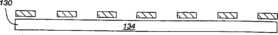
At this situation, Fig. 6 A to Fig. 6 C shows a kind of side view, as the alternative form of institute's discussion method among Fig. 5 A to 5D.In Fig. 6 A to Fig. 6 C, quality is that the thin slice 130 of substrate support material is formed the cross section of thickness less than diamond or superfinishing particle 20.When these particles were pressed into thin slice 130, the thickness of thin slice can force these particle 20 outstanding substrate support materials 134.Lamellar body 134 in aforesaid mode, permeates with jeweller's solder subsequently.
Although at the diamond grains that distributes with pattern form, the behaviour in service of jeweller's solder 28 was discussed already, so it can be applied to the diamond grains that distributes with random fashion with being equal in the substrate support material.As soon as diamond has placed in the substrate support material, contain chromium, manganese, aluminium or silicon, and quality is the jeweller's solder of non-volatile metal substantially, promptly melted and be poured on the substrate support material.This liquid solder permeates the substrate support material, and diamond grains is combined with the substrate support material.
Remove can with traditional type substrate support material, outside using such as the metal dust accompany each other, jeweller's solder also helps novel supporting material, the use shown in Fig. 7 A to Fig. 7 B.Especially referring to Fig. 7 A, show the substrate support material 200 of a certain saw with piece portion among the figure, wherein this piece portion totally is marked with 20.Substrate support material 200 includes several grooves of offering with specific distance 214.
For forming the meticulousr cutting of a kind of processing piece portion, substrate support material 200 is placed in one by in the made mould of refractory material (such as graphite or metal).Diamond grains (Fig. 7 B) is poured in the groove 214, to filling up the groove that these open wide.Jeweller's solder adds to the top of these grooves.After infiltration, scolder is these grooves of filling, and combines with diamond grains 20 and substrate support material 200, to form a kind of complete saw piece portion.In this geometric shape, diamond grains is to form the cutting edge of saw with piece portion (Fig. 7 B), but not generally spreads all over matrix in the conventional tool.The personage who is familiar with this skill will observe and learn by experience, and this kind structural form is possible hardly according to prior art, because its substrate support material 200 is required mechanically diamond to be immobilizated in suitable part.Than, use jeweller's solder that the diamond grains post is positioned in groove, the hole etc., because this scolder not only in conjunction with diamond but also in conjunction with supporting material, makes diamond be immobilizated in appropriate location (as shown in Figure 8).Although the embodiment shown in Fig. 7 A to Fig. 7 B forms diamond " fin ", so also can form the needle-like jewel post.Moreover, can form groove, hole etc., forming this kind grain post, no matter it is linearity person or along any required direction bending.Therefore, the Drawing upon daily experience, piece portions such as the personage who is familiar with this skill can develop to cut, bores, polishing give being customized to being suitable for specific use occasion.Employed diamond grains can be the diamond particulate, perhaps has the compound crystal type diamond (PCD) of heat endurance.Permeate not only condensable matrix powder, and also can form one-piece type jewelling tool securely in conjunction with diamond.
Example one
Diamond particulate (SDA-85 of De Beers company manufacturing) with 40/50 sieve mesh mixes mutually with iron powder and a kind of organic bond of granularity greater than Unite States Standard 200 meshes, be 20 the to form a kind of diamond concentration mixture of (cumulative volume 5%).This mixture is colded pressing in punching block, to form the bulk that saw blade sawtooth is used.Just base places in the graphite jig, and spreads the powder with NicrobrazLM thereon.Make this mould under vacuum, be heated to about 1,050 ℃, kept 20 minutes.The scolder that has permeated at that time combines with diamond and substrate support powder, and forms a block sawtooth.Make 24 block sawtooth of this kind, and it is trimmed to required tolerance.With these block sawtooth hard solders on the steel saw blade of one 14 inches circles.This saw blade can more traditional diamond saw be fast cutting speed just, cutting granite.In addition, than traditional diamond saw, the saw blade of making through this method has long service life.
Cutting element of the present invention, its obvious advantage that surpasses the prior art cutting element is to be that this instrument can give the mode of use.Diamond saw is typically the form of making saw blade, and its direction that mat is identical in each changes is rotated and cut workpiece.This unidirectional motion causes a kind of " tail stays " phenomenon, and promptly along the direction of rotation opinion, the matrix material that is positioned at diamond grains the place ahead is worn and torn, and is positioned at the protection that diamond grains matrix material behind then is subjected to diamond grains.Therefore, being positioned at diamond matrix material behind continues diamond grains is immobilizated in original position.If the saw counter-rotating, then diamond grains can easily be dashed on matrix.
Yet, annular saw only can cut workpiece to certain depth, promptly less than half of saw diameter.The workpiece that the desire cutting is thicker is typically the use bow saw.Because the reciprocally motion of these saws is so diamond grains must be immobilizated in each flank of tooth.The result is that the tail of diamond matrix stays to be maintained diamond grains is immobilizated in original position.Reason is for this reason made reciprocating type diamond saw blade and is not used for sawing rigid stone material such as granite as yet.But only be used to cutting soft stone material such as marble.
The present invention can allow diamond be able to mat hard solder and be subjected to fixing with chemical mode.Therefore, the matrix tail portion of staying need not to support diamond.The result is, can be used for cutting hard material on the reciprocating type saw according to the instrument of manufacturing of the present invention.This breakthrough can be expanded the range of application of diamond, open limitation because of prior art make previous can not market.
Therefore, the present invention discloses a kind of improved method that is used to make diamond saw.More than illustrate and illustrate and only be intended to illustration some potential use occasion of the present invention.The personage who is familiar with this skill is understood that the present invention is applicable to scope vast practicality occasion and application scenario.Under the prerequisite that does not depart from scope of the invention essence, the many embodiment of the present invention and the example of deriving, it is different from as herein described, and many modification, changes form and equivalent constructions, will understand because of the present invention, or inspired by it.Therefore, although the present invention was described in detail at its preferred embodiment at this already, should be understood that this announcement only is illustration and illustrates the present invention, its purpose only is the invention provides complete and effectively disclosing.The preamble disclosure is not to be used for limiting the present invention, perhaps gets rid of other any this kind forms of implementation, reorganization form, derivative form, change form and equivalent constructions, and the present invention is only limited by appended patent claim and equivalents thereof.