CN1083339C - Liquid discharging head and liquid discharging device - Google Patents
Liquid discharging head and liquid discharging device Download PDFInfo
- Publication number
- CN1083339C CN1083339C CN97117438A CN97117438A CN1083339C CN 1083339 C CN1083339 C CN 1083339C CN 97117438 A CN97117438 A CN 97117438A CN 97117438 A CN97117438 A CN 97117438A CN 1083339 C CN1083339 C CN 1083339C
- Authority
- CN
- China
- Prior art keywords
- liquid
- jet head
- bubble domain
- bubble
- thermogenesis
- Prior art date
- Legal status (The legal status is an assumption and is not a legal conclusion. Google has not performed a legal analysis and makes no representation as to the accuracy of the status listed.)
- Expired - Fee Related
Links
Images


Classifications
-
- B—PERFORMING OPERATIONS; TRANSPORTING
- B41—PRINTING; LINING MACHINES; TYPEWRITERS; STAMPS
- B41J—TYPEWRITERS; SELECTIVE PRINTING MECHANISMS, i.e. MECHANISMS PRINTING OTHERWISE THAN FROM A FORME; CORRECTION OF TYPOGRAPHICAL ERRORS
- B41J2/00—Typewriters or selective printing mechanisms characterised by the printing or marking process for which they are designed
- B41J2/005—Typewriters or selective printing mechanisms characterised by the printing or marking process for which they are designed characterised by bringing liquid or particles selectively into contact with a printing material
- B41J2/01—Ink jet
- B41J2/135—Nozzles
- B41J2/14—Structure thereof only for on-demand ink jet heads
- B41J2/14016—Structure of bubble jet print heads
- B41J2/14032—Structure of the pressure chamber
- B41J2/14048—Movable member in the chamber
Abstract
The present invention provides a liquid discharging head which comprises a discharge port, a liquide for discharging, a bubbling region in which heat energy from a heat generating member applied to the liquid to generate the bubble, a movable member that can move between a first position and a second position which is located in the face of the bubbling region. The specificity of the liquid discharging head is the heat generating member in which there is a bubbling region involved in the generation of the bubble. A center of the width of the heat generating member and a center of the width of an effective bubbling region with respect to a flow direction of the liquid are identical. The conditions of the bubble generation region are given as follows: the width of the effective bubbling region is less than or equal to a width of the bubble generation region is less than or equal to the width of the heat generating member.
Description
The present invention relates to a kind of jet head liquid that utilizes new ejector principle to spray to specify liquid, relate in particular to and have jet head liquid and the liquid injection device that makes the structure of displaceable element displacement with the generation bubble.
Jet head liquid of the present invention can apply in the various device, for example printer, duplicator, have communication system facsimile machine, have the word processor of printer or like and the industrial recording equipment that links to each other with one or more various treatment facilities, can be with it at the enterprising line item of record carrier, for example on following record carrier: paper, silk, fiber, textile, skin, metal, plastic material, glass, timber, ceramic material or the like.
Be noted herein that the image that provides to have meaning not only is provided " record " among the present invention.For example on record carrier, provide character or pattern, and refer to provide the image that does not have concrete meaning, for example on record carrier, provide decorative pattern.
One of traditional known recording method is an ink-jet method, in this method, heat energy is delivered to ink, thereby state is changed, and is accompanied by the change of this state, the volume of ink changes (foaming) rapidly, change according to this state and to produce an active force, ink is ejected from a spout by this active force, and these deposit of ink on record carrier, thereby form an image, so-called bubble jet writing-method that Here it is.As disclosed in the specification of U.S. Patent No. 4723129, the electrothermal transducer that utilizes the recording equipment of this bubble jet writing-method to have the spout that is used for ink-jet, the ink flow channel that links to each other with each spout usually and be used for energy producing unit, thus can the ink in the ink flow channel be ejected.
Above-mentioned recording method can obtain high-quality image under high-speed and low noise, in addition, owing to carry out the shower nozzle of this recording method many spouts that are used for ink-jet can be set to high-density, therefore it has many advantages: for example, utilize the equipment of compact conformation just can easily obtain the document image of fine definition.Therefore, this bubble jet recording method is used to comprise printer, duplicator, facsimile machine etc., and be used to industrial system, for example printing in textiles equipment in many office equipment in recent years.
Along with the application of bubble jet technology in each field product constantly enlarges, in recent years, urgent day by day to following various requirement.
For example,, must be optimized, do some adjustment as thickness to diaphragm to thermogenesis element in order to satisfy to improving the requirement of energy utilization efficiency.This technology gives the thermal energy transfer that produces the transmission efficiency of liquid very effective to improving.
For high-quality image is provided, the requirement of transmission condition has been proposed, so that realize the well liquid jet method of ink-jet, or based on high velocity jet, the stable foaming realized good ink-jet ability.From this position of high-speed record, proposed the convection channel structure and carried out improved requirement, so that can make jet head liquid have very high additional speed to the injected liquid of liquid flowing channel additional (replenishing again).
In the structure of this liquid flowing channel, draft among the open No.63-199972 as Japanese patent application, the structure of this circulation road has been described, shown in Figure 22 A and 22B.In this piece publication, invent this circulation road structure and shower nozzle manufacture method and noticed the echo that is produced (with the pressure of propagating in the opposite direction towards spout side, it is the pressure that is directed to fluid chamber 12) when bubbling.Because this echo is not towards injection direction, therefore think that all it is a kind of energy loss.
In the invention shown in Figure 22 A and the 22B, disclose a kind of valve 10, it is arranged on the place that separates with bubble domain, and is positioned at the opposition side of spout 11, and said opposition side is for thermogenesis element 2.Bubble domain is formed by thermogenesis element 2.
In Figure 22 B, valve 10 has been made explanation, these valve 10 usefulness sheet materials or similar material are made, and it has an initial position, and at this initial position, valve 10 is close to the top of circulation road 3, and along with the generation of bubble, valve 10 crashes into circulation road 3.This invention disclosed is to control a part of aforesaid echo by valve 10, thereby suppresses energy loss.
Yet, in this structure,, notice clearly and utilize valve 10 control section echoes that it is unpractical spraying for liquid by the situation that produces bubble in this circulation road 3 that holds atomizing of liquids is studied.
Discuss as the front, the initial and injection of echo itself does not have direct relation.When echo occurring in circulation road 3, shown in Figure 22 B, the outer pressure directly related with injection of bubble has been easy to from circulation road 3 atomizing of liquids.So control echo obviously, or rather, the control section echo can not be to spraying the very big effect that produces.
On the other hand, in this bubble jet recording method, heating constantly, and thermogenesis element always contacts with ink, will be burnt owing to the lip-deep ink of thermogenesis element like this, thus form deposit.According to the difference of ink kind, might form a large amount of deposits, this can cause bubbling unstable, and makes and be difficult to carry out ink-jet in an orderly manner.Therefore, people wish to obtain a kind of method always, and the performance that does not change injected liquid just can be carried out jetting fluid well, even this liquid is easily destroyed its performance by heat energy or this liquid is difficult for obtaining fully to bubble.
From this viewpoint, proposed to utilize the not method of liquid of the same race, a kind of liquid (foam liquid) that produces bubble by heat energy, another kind of injected liquid (jetting fluid), when producing bubble, this method can pass to jetting fluid to pressure, thereby sprays this jetting fluid, for example, draft open NO.61-69467 and disclosed situations such as NO.55-81172, United States Patent (USP) NO.4480259 at Japanese patent application.In these publications, ink as jetting fluid is separated well by the fexible film and the foam liquid of silicon rubber or similar material, make jetting fluid directly not contact with thermogenesis element, the pressure (to call foaming pressure in the following text) that is produced when bubbling in the foam liquid is sent to jetting fluid by fexible film.Adopt this structure, this method can prevent to produce deposit on the surface of thermogenesis element, and has improved free degree of jetting fluid selection or the like.
Yet, in the injector head of this structure, as mentioned above, jetting fluid and foam liquid are separated out fully, because foaming pressure is to be out of shape by the expansion of fexible film to be transmitted to jetting fluid, the pressure that therefore bubbles is absorbed by fexible film to a great extent.In addition, the deformation of fexible film neither be very big, therefore, reduced the service efficiency and the jet power of energy, although can reach this effect by jetting fluid and foam liquid are separated also.
Theme of the present invention is from never advised viewpoint in the past, the basic spray characteristic of liquid jet method is brought up to one before unpredictable level.Said liquid jet method is to realize atomizing of liquids by form traditional basically bubble (especially, bubble be accompanied by film boiling and form) in liquid flowing channel.
Get back to now on the drop ejector principle, for a kind of brand-new liquid jet method bubble, in my innocent life that utilizes is provided, some inventors have carried out extensive and deep research, in this method, have used shower nozzle etc.At that time, in first technical research that they carry out, starting point is placed in the operation of displaceable element in the liquid flowing channel, thereby the principle of displaceable element mechanism in the analysis liquid flowing channel, in second technical research, on drop ejector principle when they are placed on starting point by the bubble hydrojet, in the 3rd technical research, they are placed on starting point on the bubble domain of the thermogenesis element that is used to form bubble.
Based on these analysis and research, they have set up the brand new technical of controlling bubble fully, control to bubble realizes by following structure, the free end of displaceable element and the position of support end relation are to be provided with like this, free end is positioned at the spout side, downstream just, and displaceable element is arranged in the face of thermogenesis element or bubble domain.
In addition, by considering to be passed to by bubble itself energy of atomizing of liquids, the biggest factor that discovery can improve jet performance in a large number is a bubble downstream augmenting portion.That is to say, clearly,, just can improve ejection efficiency and jet velocity by bubble downstream augmenting portion Guide spray direction.This just guides the inventor into one and compares and the extra high level that seems with the conventional art level, thereby the downstream augmenting portion of bubble is shifted to fully free end one side of displaceable element.
In addition, also find preferably must consider each structural detail, as displaceable element, liquid flowing channel etc., they are relevant with the increase of downstream bubble in the bubble domain that is used to generate bubble, for example, with through the electrothermal transducer regional center along the downstream of the center line of liquid flow direction or increase relevant with the bubble in the downstream at the surf zone center that is used to bubble.
In addition, also find, can improve the speed of replenishing again of liquid greatly by the setting of displaceable element position and the structure setting of liquid supply passage.
By these researchs with from these comprehensive viewpoints, drawn some technological know-hows, therefrom drawn good liquid ejector principle, some inventors and applicant have proposed many applications about these principles, based on these inventions, the inventor has had better opinion.
What the inventor recognized a bit is, a kind of high density liquid injector head is provided, and it has more stable jet power, and especially the inventor has considered the position relation between the thermogenesis element and second fluid passage in the present invention.
Main goal of the invention of the present invention is as follows.
First purpose of the present invention provides a kind of jet head liquid and a kind of liquid injection device, and they can be by the relation of the position between bubble domain and the thermogenesis element, more concentrated upside or the spout side of more effectively being delivered to of the increase of bubble.
Second purpose of the present invention provides a kind of jet head liquid and a kind of liquid injection device, they can reduce above the thermogenesis element gathering of heat energy in the liquid, thereby improve ejection efficiency and expulsion pressure, and they can reduce the remaining bubble on the thermogenesis element, spray thereby can carry out better fluid.
The 3rd purpose of the present invention provides such jet head liquid and liquid injection device, they are by suppressing that form because of echo and the effect opposite inertia force of feed flow direction, thereby improve liquid alternate frequency, raising print speed etc. again, and reduce the amount of recovery of flexure plane by the valve function of displaceable element.
The 4th purpose of the present invention provides such jet head liquid and liquid injection device, and they can reduce the deposit on the thermogenesis element, can widen the range of application of atomizing of liquids, can have quite high ejection efficiency and jet power.
The 5th purpose of the present invention provides such jet head liquid and liquid injection device, and they can increase the selection free degree of injected liquid.
The 6th purpose of the present invention provides such jet head liquid and liquid injection device, and they make that above-mentioned jet head liquid is easy to make.
To achieve these goals, the invention provides a kind of jet head liquid, it comprises a spout, be used for atomizing of liquids, a bubble domain is applied to heat on the liquid by thermogenesis element, thereby produces bubble, a displaceable element, in the face of the bubble domain setting, and can move between the primary importance and the second place, the second place is far away apart from bubble domain than primary importance, in bubble domain, produce bubble, thereby formation pressure, under this foaming pressure effect, this displaceable element moves on to the second place from primary importance, and this displacement by displaceable element, bubble expansion towards downstream big than towards the upstream, said upstream, the downstream is relatively towards the direction of spout, so just liquid is ejected, wherein, in thermogenesis element, a bubble domain that is used to produce bubble is arranged, for the flow direction of liquid, the central authorities of thermogenesis element width are identical with effective bubble domain, and the restrictive condition of bubble domain is as follows:
The width of the width≤thermogenesis element of the width≤bubble domain of effective bubble domain.
In addition, in above-mentioned injector head,, can also one free end be arranged, under the effect of foaming pressure, said free end be moved, thereby said pressure guiding spout side, the restrictive condition of bubble domain is as follows in the spout side in the face of said thermogenesis element:
The width of the width≤thermogenesis element of the width≤bubble domain of effective bubble domain.
In addition, feature of the present invention also is: in above-mentioned injector head, and (width of thermogenesis element)-8 μ m≤(width of bubble domain).
In addition, feature of the present invention also is: in above-mentioned injector head, when the flow direction of liquid is that the restrictive condition of bubble domain is as follows along thermogenesis element with effectively during the length direction of bubble domain: the effective length of the length≤thermogenesis element of the length≤bubble domain of bubble domain.
In addition, feature of the present invention also is: in above-mentioned jet head liquid, and the area of the area≤displaceable element of effective bubble domain, and when inactive state, displaceable element is closed effective bubble domain hermetically.
Have again, in above-mentioned injector head,, one free end is arranged, under the effect of foaming pressure, said free end is moved in the spout side in the face of the thermogenesis element setting, thereby said pressure guiding spout side; Also has a feed path, be used for from the upstream providing liquid along the said upward thermogenesis element in surface of the said displaceable element of more close thermogenesis element, the condition of bubble domain is as follows: the effective width of the width≤thermogenesis element of the width≤bubble domain of bubble domain.
In addition, a kind of jet head liquid of the present invention comprises first liquid flowing channel, links to each other with spout; Second liquid flowing channel has a bubble domain, gives liquid the heat energy effect by thermogenesis element, thereby produce bubble in liquid; One displaceable element, be arranged between first liquid flowing channel and the said bubble domain, in the spout side one free end is arranged, according to the formed pressure of the bubble that in bubble domain, is produced, free end is moved to the described first liquid communication passageway side, thereby the lead spout side of said first liquid flowing channel of said pressure, it is characterized in that: the bubble domain that in thermogenesis element, is useful on foaming, thermogenesis element effective bubble domain central and with respect to liquid flow direction is identical, and the condition of bubble domain is as follows: the width of the width≤thermogenesis element of the width≤bubble domain of effective bubble domain.
Also has a kind of jet head liquid, comprise: a groove element, integrally have many spouts that are used for atomizing of liquids, many grooves are used to form many first liquid flowing channels, and these liquid flowing channels link to each other with separately spout, and it is corresponding with spout separately, one sunk part is used to form the first public sap cavity, provides liquid to said many first liquid flowing channels; One element substrate wherein is provided with many thermogenesis elements, is used for by the heat energy effect is given liquid and produced bubble at liquid; One partition wall, be arranged between said groove element and the said element substrate, be used to form a part with the conduit wall of corresponding second liquid flowing channel of said thermogenesis element, and has displaceable element, be arranged on position in the face of said thermogenesis element, under the effect of said foaming pressure, each displaceable element moves to first liquid flowing channel; Wherein: the part of utilizing each thermogenesis element to produce bubble is defined as a bubble domain, in each thermogenesis element, a bubble domain that is used to bubble is all arranged, each thermogenesis element width one effective bubble domain central and with respect to liquid flow direction is identical, and the condition of each bubble domain is as follows: the width of the width≤thermogenesis element of the width≤bubble domain of effective bubble domain.
In addition, a kind of liquid injection device comprises above-mentioned jet head liquid and drives signal supply device that this driving signal supply device is used to provide one to drive signal, and liquid is sprayed from jet head liquid.
Have, a kind of liquid injection device comprises above-mentioned jet head liquid and record carrier conveying device again, and this record carrier conveying device is used to carry record carrier, and this record carrier is the liquid that is used to receive from the jet head liquid ejection.
In the present invention, by such characteristic: the width of the width≤thermogenesis element of the width≤bubble domain of effective bubble domain makes bubble increase towards the top or towards the spout side.This just can make jet power more stable.And, more highdensity layout can be obtained, thereby the quality of image can be improved.
In addition, the present invention is based on above-mentioned brand-new ejector principle and realizes, thereby according to the synergy between liquid jet method of the present invention, the first-class displaceable element that can obtain bubble and can be subjected to displacement of injection by bubble, therefore, near the spout liquid can be injected effectively, thereby compare with injection method, the injector head of traditional bubble jet formula, improved ejection efficiency.For example, in the most preferred embodiment of the present invention, obtained breakthrough ejection efficiency, it improves more than the twice.
Adopt further feature structure of the present invention, even in long-term storage under low temperature or low humidity, also can prevent to spray failure, perhaps, even failure has taken place to spray, injector head also can be got back to normal situation well immediately, just needs some recovery operations to get final product, and for example sprays or absorb recovery in advance.
Especially, long-term storage, for the injector head with 64 spouts of traditional bubble jet formula, nearly all spout all causes and sprays failure, and for injector head of the present invention, approximately has only half or spout still less to cause and spray failure.For need spraying in advance in order to recover these injector heads, in traditional injector head, each spout needs several thousand injections in advance, and recovers injector head of the present invention, sprays about 100 times just enough in advance.This means that the present invention can shorten recovery period, can reduce the liquid because of recovering to lose, and can significantly reduce operating cost.
Especially, according to the present invention, by being used to improve the liquid structure of supplementary characteristic again, the very high responsiveness when having obtained continuous injection, the stable increase of bubble, the stability of drop, and can high-speed record or the high-quality record that sprays based on high-speed liquid.
From some embodiment, will be appreciated that other effect of the present invention.
The present invention used term " upstream " and " downstream " in description defines through the flow direction of bubble domain (or displaceable element) to jet from the liquid source of supply with respect to overall liquid, or describe about this structure direction.
In addition, the spout side part of " downstream " of bubble itself expression bubble, this part mainly directly is used for liquid droplets.More particularly, it is meant the downstream part of the bubble on above-mentioned flow direction or said structure direction, and this perhaps is meant the bubble that occurs in the downstream of thermogenesis element regional center for bubble center.
In description of the invention, used " sealing substantially " state is meant the sealing state with this degree, when bubble increases, can stop bubble to be run away by the slit (crack) around the displaceable element before displaceable element is subjected to displacement.
" partition wall " described in the present invention broadly can be the wall (it can comprise displaceable element) for the zone of this and the direct fluid connection of spout and bubble domain being separated and being inserted, more particularly, it can be to be used for the liquid flowing channel separated wall of the liquid flowing channel of bubble domain with direct and spout fluid connection, thereby, can prevent the mixing of liquid in each liquid flowing channel from narrowly.
In addition, " free end portion " of the displaceable element described in the present invention is meant and comprises free-ended part and its adjacent domain that free end is the downstream side of displaceable element, also comprises near some zones of corner, downstream of displaceable element in addition.
In addition, " the free end zone " of the displaceable element described in the present invention is meant near the zone free end itself as displaceable element downstream side, the free end or comprises the zone of free end and side.
In addition, " liquid flowing channel is to the resistance of displaceable element " described in the present invention is meant the generation along with bubble, and when displaceable element was removed from bubble domain, the liquid in the liquid flowing channel imposed on the resistance of displaceable element.Therefore, the present invention includes all and control the technology contents of the action of displaceable element, just by changing resistance, by forming a resistance slope, be used as the application of resistance by a physical barriers device, by be substantially stopper be used to disturb liquid, thereby the acquisition resistance, or the like.Hereinafter, this resistance will be called " resistance " or " flow resistance " simply.
Figure 1A, 1B, 1C and 1D are the profiles of an example of the applied jet head liquid of the present invention;
Fig. 2 is the perspective view that the part of the applied jet head liquid of the present invention is cut open;
Fig. 3 is illustrated in the conventional spray head, the schematic diagram that pressure is outwards propagated from bubble;
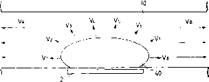
Fig. 4 is illustrated in the applied jet head liquid of the present invention, and pressure is from the schematic diagram of the outside propagation condition of bubble;
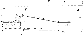
Fig. 5 is the schematic diagram that is used for illustrating the applied jet head liquid liquid flow of the present invention;
Fig. 6 is the schematic diagram that is used to illustrate the displaceable element and the first liquid flowing channel structure;
Fig. 7 A, 7B and 7C are the schematic diagrames that is used to illustrate displaceable element and liquid flowing channel;
Fig. 8 A and 8B are the schematic diagrames of notion between the expression thermogenesis element and second liquid flowing channel, position relation;
Fig. 9 A and 9B are the figure of position relation between thermogenesis element and second liquid flowing channel in the expression example 1;
Figure 10 A and 10B are the figure of position relation between thermogenesis element and second liquid flowing channel in the expression example 2;
Figure 11 A and 11B are the figure of position relation between thermogenesis element and second liquid flowing channel in the expression example 3;
Figure 12 A, 12B and 12C are the figure that is used to illustrate other shape of displaceable element;
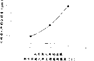
Figure 13 is the curve map that concerns between expression area of thermogenesis element and the ink ejection amount;
Figure 14 A and 14B are the schematic diagrames of position relation between expression thermogenesis element and the displaceable element;
Figure 15 is the curve map that concerns the distance of expression from the thermogenesis element edge to support end and the displaceable element displacement;
Figure 16 is the schematic diagram that is used to illustrate position relation between thermogenesis element and the displaceable element;
Figure 17 A and 17B are the longitudinal sectional drawings of jet head liquid of the present invention;
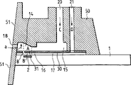
Figure 18 is the profile that is used to illustrate the feed path of jet head liquid of the present invention;
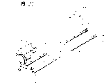
Figure 19 is the part decomposition diagram of injector head of the present invention;
Figure 20 is the structural representation of liquid injection device of the present invention;
Figure 21 is the block diagram of recording equipment of the present invention;
Figure 22 A and 22B are the schematic diagrames that is used to explain the liquid flowing channel structure of traditional jet head liquid;
(ejector principle)
Adopting jet head liquid of the present invention is to realize according to new ejector principle, will describe jet head liquid below.
What at first describe is an example, in this example, can form a pressure when producing bubble, the direction of propagation by controlling this pressure and the augment direction of bubble, thus improve the ejection efficiency and the jet power of atomizing of liquids.
Figure 1A to 1D is the profile along the liquid flowing channel direction of the applied jet head liquid of the present invention, and Fig. 2 is the perspective view that the part of jet head liquid is cut open.
Jet head liquid of the present invention comprises: element substrate 1; Thermogenesis element 2 (being the heat-resistant element that is shaped as 40 μ m * 105 μ m in the present embodiment) is used for energy generating element, provides energy to liquid, thus atomizing of liquids, and it is installed in the element substrate 1; With the thermogenesis element 2 corresponding liquid flowing channels 10 that are positioned at above the element substrate.Liquid flowing channel 10 and corresponding spout 18 fluid connections, and also with public fluid chamber 13 fluid connections, be used for to numerous liquid flowing channels 10 feed fluids, thereby make every liquid flowing channel 10 can both receive the liquid from public fluid chamber 13, the amount of liquid that is received equals from the amount of liquid of spout ejection.
On the element substrate and in every liquid flowing channel 10, the displaceable element of a sheet is arranged, have a plate part, it is cantilevered fashion, makes with elastomeric material, and as metal, this displaceable element is provided with in the face of above-mentioned thermogenesis element 2.One end of displaceable element is fixed on a base (support member) 34 or other object, and this base is on the conduit wall of liquid flowing channel 10 or in the element substrate with photosensitive resin manufacture.This support structure displaceable element, and constitutes a support end (support section) 33.
When atomizing of liquids, liquid flows to spout 18 from public fluid chamber 13 through displaceable element 31, (support section: 33 upstream sides that are located in this liquid flow support end), the free end of displaceable element (free part) 32 is positioned at the downstream of this support end 33 to the support end of displaceable element 31.
By thermogenesis element 2 is heated, heat energy just acts on the liquid in the bubble domain of giving between displaceable element 31 and the thermogenesis element 2 11, thereby produces bubble by the film boiling phenomenon in liquid, and is said in this specification as United States Patent (USP) 4723129.Bubble and the pressure preferential interaction that produces based on bubble on displaceable element, thereby make displaceable element 31 open very greatly in the spout side around support end 33, as Figure 1B and 1C or shown in Figure 2.State after the moving of the displacement of displaceable element 31 or it is just the increase of bubble itself with the spout that leads of the pressure propagation when bubbling.
To describe basic ejector principle of the present invention below.One of most important principle is among the present invention: by the pressure or the bubble itself of bubble, primary importance when making displaceable element over against bubble from inactive state moves to and moves the second place later, so the downstream that the pressure guiding spout place that displaceable element 31 is just produced bubble itself or when bubbling is located.
Fig. 4 represents situation of the present invention, and Fig. 3 represents not use traditional liquid flowing channel structure of displaceable element, below this principle will be described by the contrast of Fig. 4 and Fig. 3.Here, V
AExpression pressure is towards the direction of propagation of spout, and V
BThen represent the direction of propagation of pressure towards the upstream.
Traditional injector head shown in Figure 3 is not used in the structure of regulating the direction of propagation that produces bubble 40 formed pressure.Therefore, the pressure of bubble 40 is just propagated on each direction perpendicular to bubble surface, as V
1-V
8Shown in.In these pressure, along V
AThe pressure component that direction is propagated sprays being beneficial to liquid, and they are more near the pressure of spout, i.e. V
1To V
4, they are piths of decision liquid ejection efficiency, jet power, jet velocity etc.In addition, V
1Be effectively active force, because it and injection direction V
AThe most approaching, on the other hand, V
4Comprised one less relatively along V
AThe component of direction.
In contrast to this, in the example of the present invention shown in Figure 4, displaceable element 31 is used for the pressure propagation direction V bubble
1To V
4Guiding downstream (spout side), thus they are become along V
ADirection is propagated, and therefore the pressure of bubble 40 is more helped directly, effectively sprays.If there is not displaceable element, V then
1To V
4Will propagate by the same one way or another with situation shown in Figure 3.With guiding V
1-V
4The mode of the direction of propagation the same, the augment direction of bubble itself also is directed to the downstream by this way, so bubble increases manyly in the downstream than upstream side.Like this, control the augment direction of bubble itself, thereby essence ground has improved ejection efficiency, jet power and jet velocity or the like, and also controlled the pressure propagation direction of bubble by utilizing displaceable element.
Get back to Figure 1A to 1D now, the spraying of the jet head liquid of present embodiment is described in detail.
What Figure 1A represented is at energy, and for example electric energy puts on thermogenesis element 2 state before, therefore, also just is in thermogenesis element and produces heat energy state before.The important point is, displaceable element 31 is with respect to the bubble setting that heat produced of thermogenesis element, thereby at least in the face of bubble downstream part.Just, in order to allow the downstream part of bubble act on displaceable element, the structure of liquid flowing channel is provided with like this, and displaceable element 31 extends to the downstream (or by thermogenesis element regional center 3 and perpendicular to the downstream of the straight line of circulation road length direction) of thermogenesis element regional center 3 at least.
In the represented state of Figure 1B, electric energy or similar energy have acted on thermogenesis element 2, thereby thermogenesis element 2 is heated, so heat energy makes a part of liquid in the bubble domain 11 obtain heating, thereby produce bubble according to film boiling.
At this moment,, make displaceable element 31 move to the second place from primary importance by producing the pressure that bubble 40 forms, thereby the pressure propagation direction of bubble 40 spout that leads.Here, the important point is, as mentioned above, the free end 32 of displaceable element 31 is positioned at downstream (or spout side), and support end 33 is positioned at upstream side (or public sap cavity side), therefore displaceable element has at least the part can be over against the downstream part of thermogenesis element, just over against the downstream part of bubble.
In the represented state of Fig. 1 C, bubble 40 further increases, according to producing bubble 40 formed pressure, displaceable element 31 further displacements.Bubble in the downstream than increasing manyly in the upstream, thereby substantially exceed the primary importance (some line position) of displaceable element.So can know, along with the increase of bubble 40, displaceable element 31 moves gradually, the direction that the pressure propagation direction of this mobile permission bubble 40 and volume change easily, be bubble towards free-ended augment direction all by the spout that as one man leads, this has also improved simultaneously ejection efficiency.When displaceable element led spout to the pressure of bubble and bubble generation, displaceable element seldom stoped this pressure propagation, and it can also effectively control the direction of propagation of bubble and the augment direction of bubble according to the size of propagation pressure.
In the represented state of Fig. 1 D, behind film boiling,, thereby bubble 40 is shunk and disappearance owing to the pressure in the bubble reduces.
Because displaceable element itself has elasticity, and when bubble shrinkage, can produce a negative pressure, thereby they common form a restoring force, and under the effect of this restoring force, the displaceable element 31 that has been moved to the second place is got back to the initial position (primary importance) among Fig. 1 again.In case bubble shrinkage, liquid will flow into bubble domain 11, reduce and the additional liquid that is ejected with the volume that replenishes bubble, as shown in FIG., V
D1, V
D2Expression is from upstream side (B) or the next liquid stream of public sap cavity effluent, V
cThe liquid stream that expression comes from the spout effluent.
The front has illustrated the operation that displaceable element carries out along with the generation of bubble and the spraying of liquid, has explained the supplementary information again of liquid in the applied jet head liquid of the present invention then.
With reference to Figure 1A to 1D, the liquid supply mechanism among the present invention is explained in more detail below.
Behind Fig. 1 C, bubble 40 experience maximum volume states enter contraction process then.In the bubble shrinkage process, there is the liquid of q.s to flow into bubble domain, to replenish the volume of the bubble that disappears from the spout side of first liquid flowing channel 14 and the public sap cavity 13 of second liquid flowing channel 16.In the structure of traditional liquid flowing channel, do not have displaceable element 31,, depend on than bubble domain more near spout and more approaching public sap cavity flow resistance partly from the amount of liquid of spout side and public sap cavity inflow bubble collapse position.(bubble domain is that the inertia according to circulation road resistance and liquid influences mobile).
If near the flow resistance the spout side is less, the position of more liquid from spout side inflow bubble collapse so just arranged, so just increased the amount of recovery of meniscus.Particularly, reduce near the flow resistance of spout side, to improve ejection efficiency, but can make when bubble collapse this moment, the amount of recovery of meniscus M becomes bigger, and the prolongation again of liquid just becomes longer, so this flow resistance that reduces the spout side has stoped flying print on the contrary.
In contrast to this, owing to comprise displaceable element 31 in the structure of the present invention, therefore, during bubble collapse, displaceable element one is got back to initial position, and meniscus just stops retraction.The volume W of bubble can be divided into W
1And W
2Two parts, W
1Be meant the volume of the part bubble on displaceable element 31 primary importances, W
2Be meant the volume of the bubble bottom of bubble domain 11 sides.When the change liquid level stops to bounce back, remaining W
2Volume is mainly by the liquid stream V from second circulation road 16
D2Supply with.In traditional structure, the volume of meniscus retraction approximates half of bubble volume W greatly, and that said structure can be reduced to the amount of recovery of meniscus is littler, especially, can reduce to about W
1Half.
In addition, formed pressure when utilizing bubble collapse can force mainly from the second liquid flowing channel upstream side V
D2Liquid along by the displaceable element surface of thermogenesis element side to W
2Supply with, thereby realize that liquid replenishes quickly again.
One following characteristic point is arranged: in the conventional spray head,, will cause the sharp pounding of meniscus so, thereby cause destroying picture quality here if formed pressure is finished liquid and replenished when utilizing bubble collapse.And in structure of the present invention, because being communicated with between the liquid in the liquid that displaceable element has limited the spout side first liquid flowing channel zone and the spout lateral areas of bubble domain 11, thereby make the additional again of liquid drop to a low-down level to the vibrations of meniscus.
Like this, structure of the present invention can realize that enforceable liquid replenishes again, it is to force liquid to pass through second liquid supply passage 12 to flow into bubble domain, and the retraction and the vibrations of above-mentioned meniscus have been suppressed, replenish again so that carry out at a high speed, therefore, when in use in the record field, adopting structure of the present invention, can realize the high velocity jet of stable injection and each spout, and can improve picture quality and realize flying print.
Structure of the present invention also has following effective efficiency.It can suppress to bubble pressure upstream side propagate (echo).In traditional situation, bubble produces on thermogenesis element 2, becomes the active force that liquid is pushed back upstream side (Here it is echo) near most of pressure of the bubble of public sap cavity 13 (or upstream side) in the bubble.This echo raises upstream side pressure, and the capacity of returns that causes therefrom increases, and because this moving of liquid caused inertia force, and this additional again to liquid flowing channel of having slowed down has also hindered high-speed driving.The present invention utilizes displaceable element 31 to suppress this effect towards upstream side, has therefore improved the additional properties again of liquid.
Below the effect that further feature structure and this structure of the present invention produces will be described.
Second liquid flowing channel 16 of the present invention has a liquid supply passage 12 with inwall at the upstream side of thermogenesis element 2, and this inwall is continuing (it means that the surface of thermogenesis element is not much lower) from thermogenesis element 2 approximate horizontal ground.In this case, the surface of liquid along near displaceable element 31 surfaces the bubble domain 11 from thermogenesis element 2 flows into bubble domain 11, as V
D2Shown in.This has just suppressed liquid and has stopped on thermogenesis element 2 surfaces, and removes so-called remaining bubble easily, and these remaining bubbles are that bubble that separate or that do not have to disappear stays in the gas from be dissolved in liquid.In addition, also stoped the heat energy in the liquid to gather.Therefore, can more stably repeat at high speed to bubble.Although illustrated structure has the liquid supply passage 12 of approximate horizontal inwall, but the present invention is not limited thereto, liquid supply passage can be any passage that has with the slow inwall that inclines of thermogenesis element smooth connection, as long as the shape of this passage can make liquid not stop or produce during not at feed flow turbulent flow on the thermogenesis element.
Some liquid is from V
D1Flow into bubble domain through moving meter side (by stitching 35).Foaming pressure guiding spout, can cover whole bubble domain (covering the thermogenesis element surface) with this displaceable element, for more effectively shown in Figure 1A to 1D.If the structure in that example arranges that like this when displaceable element 31 was got back to primary importance, the liquid flowing resistance between the spout near zone of the bubble domain 11 and first liquid flowing channel 14 can be bigger, therefore with confined liquid as mentioned above like that from V
D1Used injection nozzle structure flows into bubble domain 11, owing to can guarantee liquid stream V among the present invention
D2To the bubble domain feed fluid, therefore has very high fluid discharge performance.So even in this structure, displaceable element 31 covers bubble domain 11, also can keep the supply performance of liquid.
By the way, in the free end 32 of displaceable element 31 and the relation of the position between the support end 33, free end is positioned at the downstream of support end, and is for example shown in Figure 5.The effect of the augment direction guiding spout of pressure propagation direction when this structure can reach foaming and bubble, this is the same just as previously discussed.In addition, this position relation can not only reach the effect of injection, and when feed fluid, and when the flow resistance that reduces the liquid liquid flowing channel 10 in, the high speed that can reach liquid is additional again.This be because, as shown in Figure 5, when the meniscus that is in advanced position after the injection is got back to spout 18 again under surface tension effects or when liquid provides to replenish bubble collapse, free end of She Zhiing and support end 3 can interior liquid flow S1, S2, the S3 of barrier liquid circulation road 10 (comprising first liquid flowing channel 14 and second liquid flowing channel 16) like this.
Be described in detail below, in the example shown in Figure 1A to 1D, displaceable element 31 stretches out with respect to thermogenesis element 2, make that its free end 32 is relative at downstream position with thermogenesis element 2, said downstream position is for regional center 3 (by thermogenesis element regional center (passing through core) and perpendicular to the straight line of liquid flowing channel length direction).Regional center 3 is divided into upstream region and downstream area to thermogenesis element 2, as previously mentioned.This structure makes the bubble that displaceable element 31 receives pressure or forms in 3 downstreams, thermogenesis element regional center position, and helps the injection of liquid, and pressure and bubbles spout, thus essence improved ejection efficiency and jet power.
In addition, also can obtain many effects by the upstream portion of utilizing above-mentioned bubble.
Suppose that in the present embodiment the effect that helps liquid to spray also is because the free-ended up time machinery of displaceable element 31 moves generation.
In front, the jet head liquid according to new ejector principle among the present invention is described.Below with reference to accompanying drawings, the specific examples of priority application in jet head liquid described.Although following each example is all used embodiment of single current channel-style or illustrated with an embodiment of double flow channel type, should be noted that they can apply to this two kind; Except as otherwise noted.The top structure of<liquid flowing channel 〉
Fig. 6 is the profile along the liquid flowing channel direction according to jet head liquid of the present invention, and the groove element 50 that wherein has groove is arranged on the partition wall 30, and these grooves are used to form first liquid flowing channel 14 (or liquid flowing channel among Figure 1A to 1D 10).In the present embodiment, near the circulation road height the free end 32 of displaceable element 31 increases, thereby can guarantee that displaceable element has a bigger operation angle.The moving range of displaceable element can determine that displaceable element should move to an angle that comprises the spout axial angle according to the structure of liquid flowing channel, the durability of displaceable element and pressure that bubble produces or the like.
Shown in this figure, make the free-ended diameter highly be higher than spout that moves of displaceable element so just can obtain jet power transmission more fully.In this drawing, owing to, therefore can more effectively stop pressure to be run to upstream side along with the displacement of displaceable element at the liquid flowing channel overhead height at support end 33 places of displaceable element liquid flowing channel overhead height less than free end 32 places of displaceable element.Position relation between<the second liquid flowing channel and the displaceable element 〉
Fig. 7 A to 7C is the schematic diagram that is used to illustrate position relation between the displaceable element 31 and second liquid flowing channel 16, wherein Fig. 7 A is partition wall 30, displaceable element 31 and near the vertical view them, Fig. 7 B is a vertical view of removing behind the partition wall 30 second liquid flowing channel 16, and Fig. 7 D is the schematic diagram of position relation between the displaceable element 31 that is piled up of expression and second liquid flowing channel 16.In every width of cloth figure, bottom is the front side at place, spout place.
Second liquid flowing channel 16 of present embodiment has a throat 19 (the upstream side here is meant the upstream side that flows to the liquid stream of spout from the second public sap cavity through the position of thermogenesis element, displaceable element and first-class passage) at the upstream side of thermogenesis element 2, thereby form such chamber (foaming chamber) structure, it can stop foaming pressure to run to the upstream side of second liquid flowing channel 16).
In traditional injector head, the circulation road that is used to bubble is common with the circulation road that is used for the liquid injection, when a throat is set, when running into public sap cavity with the pressure of the sap cavity side that stops thermogenesis element, just need to consider that enough liquid replenishes again, thereby need the liquid flowing channel can not be too little in the basal area of throat portion.
Yet, in the present embodiment, major part is those atomizing of liquids that are positioned at first liquid flowing channel in the injected liquid, the frothed liquid that is positioned at second liquid flowing channel with thermogenesis element then is consumed seldom, therefore, the amount of the frothed liquid that is replenished to the bubble domain 11 of second liquid flowing channel 16 can be very little.So the gap of above-mentioned throat 19 just can be done very for a short time, for example little to several micron to 10 microns with several micron, thus just can further suppress the release of the interior foaming pressure of second liquid flowing channel, pressure is more concentrated on the displaceable element.So this pressure just can use as jet power by displaceable element 31, thereby can obtain higher ejection efficiency and jet power.The structure of this second liquid flowing channel 16 is not limited to above-mentioned situation, and it can be an any structure, as long as can be delivered to the displaceable element side to the formed pressure that bubbles effectively.
Shown in Fig. 7 C, the periphery of displaceable element 31 covers the each several part of the wall that constitutes second liquid flowing channel, and this just can prevent that displaceable element 31 from falling in second liquid flowing channel.This can improve the branch separating performance between above-mentioned atomizing of liquids and the frothed liquid.And this structure can be given as security the system bubble and be run away from slit, thereby has further increased expulsion pressure and ejection efficiency.Pressure when in addition, it can improve by bubble collapse and from the supplementary result of upstream side liquid make-up.
In Fig. 1 C and Fig. 6, the part of the bubble that in the bubble domain of second liquid flowing channel 16, produces, along with displaceable element 31 moves in first liquid flowing channel 16 and expansion in first liquid flowing channel 14, by determining the height of second liquid flowing channel, thereby allow bubble to expand by this way, with bubble expansion phase ratio by this way not, jet power can improve more.Expand described in order to allow bubble to resemble in first liquid flowing channel 14, the height of second liquid flowing channel 16 is preferably lower than the maximum height of bubble, especially, the height of second liquid flowing channel 16 is preferably fixed on several microns between 30 microns.In the present embodiment, this highly is 15 μ m.Position relation between<bubble domain and the thermogenesis element〉[example 1]
Fig. 8 A and 8B represent notion, the position relation between thermogenesis element and the bubble domain.Fig. 9 A and 9B represent the relation of the position between the thermogenesis element and bubble domain in this example.
In Fig. 8 A and 8B, the size of thermogenesis element 2 is 58 * 150 μ m, and the size of displaceable element 31 is 53 * 220 μ m, and the height of second liquid flowing channel 16 is 15 μ m, and the width of second liquid flowing channel 16 is 62 μ m.
In Fig. 9 A and 9B, the size of thermogenesis element 2 is 58 * 150 μ m, and the size of displaceable element 31 is 53 * 220 μ m, and the height of second liquid flowing channel 16 is 15 μ m, and the width of second liquid flowing channel 16 is 58 μ m.
Fig. 9 A and 9B are used to illustrate this example, and wherein the width of second liquid flowing channel is different from Fig. 8 A and 8B, and the width of second liquid flowing channel equals the width of thermogenesis element in this example.
In Fig. 8 A and 8B, the pressure propagation direction V of the bubble 40 that produces in the bubble domain
1To V
4Expression.Pressure is propagated on all directions, thereby arrives displaceable element 31.
In this example shown in Fig. 9 A and the 9B, the width center of bubble domain is identical (also being like this in the example of back) with the width center of thermogenesis element 2, and such position relation is arranged: (width of bubble domain)=(width of thermogenesis element).In Fig. 8 A and 8B, the pressure component V that propagates towards the edge
3, V
4, in Fig. 9 A and 9B, can upwards propagate owing to the conduit wall of second liquid flowing channel more straightly.Therefore, foaming pressure is not delivered to displaceable element with losing, and is converted into jet power, so just improved ejection efficiency.
The structure that resembles this example allows spout density height, thereby can significantly improve the quality of image.[example 2]
Figure 10 A and 10B represent the position relation of thermogenesis element and bubble domain in the example 2.
In Figure 10 A and 10B, the size of thermogenesis element 2 is 58 * 150 μ m, and the size of displaceable element 31 is 53 * 220 μ m, and the height of second liquid flowing channel 16 is 15 μ m, and the width of second liquid flowing channel 16 is 50 μ m.
Example 2 is to be provided with like this, and the width of second liquid flowing channel is 50 μ m, narrow in the ratio 1, and the relation of the position between thermogenesis element 2 and the bubble domain is restricted to: (width of bubble domain)=(width of thermogenesis element)-8 μ m.
In traditional ink mist recording law technology, so-called bubble jet recording method is in ink heat energy or similar energy, thereby cause the state of the rapid variation (foaming) that in ink, is accompanied by volume to change, according to the active force of this state variation, spray ink by spout, make ink deposition on record carrier, thereby on record carrier, form image, the area of thermogenesis element becomes just this relation with ink ejection amount, but has an invalid bubble domain S who is helpless to ink-jet, as shown in figure 13.The state that burns from the thermogenesis element as can be seen, this invalid bubble domain S be positioned at thermogenesis element around.We think from these conclusions, and about 4 μ m is wide is not included in the foaming around the thermogenesis element.
Therefore, if thermogenesis element wide be x μ m, long be y μ m, it has following relation of plane so:
(area effectively bubbles)=(x-8) (y-8) μ m.
In the present example, though effectively bubble domain is limited in from the inside of thermogenesis element periphery more than 4 μ m, it is not limited thereto, and it depends on the type and the formation method of thermogenesis element.
Therefore, this example the pressure propagation of bubble is changed into jet power, and energy loss still less, thereby has further been improved ejection efficiency by adopting the position relation among Figure 10 A and the 10B.
Usually, the size of thermogenesis element is depended in the change of ejection efficiency, and effective foaming area of thermogenesis element is certain, and ideal situation is: width x μ m=length y μ m.
Because those situations, thereby can obtain the structure higher than spout spacing.For increasing density, from the size of the thermogenesis element side determined by the spout spacing and the area that sprays necessary thermogenesis element, the spout spacing was considered to a limiting density originally.
Utilize the injector head in the example 2, its ejection efficiency was once done measurement, measurement environment is as follows:
Frothed liquid: 40% hydrous ethanol
The ink that is used to spray: dye China ink
Voltage: 20.2V
Frequency: 3KHz
The experimental result of being carried out under above-mentioned measurement environment has confirmed to compare with traditional shower nozzle that does not have displaceable element by the function of emitted dose decision with for the jet velocity of importing energy, has significantly improved.[example 3]
Figure 11 A and 11B represent thermogenesis element and the super position relation of steeping between the district in the example 3.
In Figure 11, the size of thermogenesis element 2 is 58 * 150 μ m, and the size of displaceable element 31 is that the height of 53 * 150 μ m, second liquid flowing channel 16 is 15 μ m, and the width of second liquid flowing channel 16 is 50 μ m.
The thermogenesis element width is identical with example 2 with the relation of bubble domain width, and still, the relation between the length of thermogenesis element and the length of bubble domain is different from example 2, and it is restricted to: (length of bubble domain)=(length of thermogenesis element)-8 μ m.
When adopting this position to concern, the bubble chamber of bubble domain is only formed by the thermogenesis element that can effectively produce bubble, and therefore, pressure in bubbles passes to displaceable element under the less situation of loss, and is converted into jet power, thereby has improved ejection efficiency.
Even the atomizing of liquids heat resistance is weak and might produce sediment on thermogenesis element, even atomizing of liquids and frothed liquid are different, if employing said structure, bubble also can be along with the mobile bubble domains that is full of of displaceable element, thereby make atomizing of liquids and frothed liquid be difficult to mix mutually.If the size of thermogenesis element, so just can improve the hermiticity (hermeticity) of bubble greater than the size of bubble domain, this has just prevented mixing of atomizing of liquids and frothed liquid.<displaceable element and partition wall 〉
Figure 12 A, 12B and 12C represent other structure of displaceable element 31, the seam in the reference number 35 expression partition walls wherein, and this gap-shaped becomes displaceable element 31.Figure 12 A illustrates a kind of rectangular configuration, and Figure 12 B is illustrated in the structure that support end one side narrows down, and this narrowing down helps the operation of displaceable element, and in the structure shown in Figure 12 C, support end one side is broadened, to improve the durability of displaceable element.A kind of easy operation and to have the shape of high-durability should be the structure that the width of support end narrows down with arc very much, shown in Fig. 7 A, but, the structure of displaceable element can be an any structure, enter second liquid flowing channel as long as can prevent displaceable element, and be convenient to the operation and good endurance get final product.
Among the embodiment in front, the displaceable element 31 of sheet and the partition wall 30 with this displaceable element be with thick be that the nickel of 5 μ m is made, but, also be not limited thereto, the material of making displaceable element and partition wall can have the performance, flexible to guarantee the displaceable element excellent operation, to allow to form the material of micro gap and select of opposing foam liquid and jetting fluid dissolving from those.
In the material preferred example of displaceable element, this material comprises durable material, for example metal, as silver, nickel, gold, iron, titanium, aluminium, platinum, tantalum, stainless steel, phosphor bronze and their alloy, resin material for example has the material of nitro, as acrylonitrile, butadiene or styrene, has the material of amide groups, as polyamide, material with carboxyl, as polycarbonate, have aldehyde radical as polyacetals, have sulfuryl as polysulfones, liquid crystal polymer, and their chemical compound; Also be included in the material that has durability in the ink, metal for example, as gold, tungsten, tantalum, nickel, stainless steel, titanium, their alloy, be coated with a kind of like this material of metal, resin material with amide groups, as polyamide, resin material such as polyacetals with aldehyde radical, resin material such as polyether etherketone (polyetheretherketone) with ketone group, resin material such as polyimides with imido grpup, resin material such as urea formaldehyde with hydroxyl, resin material such as polyethylene with ethyl, resin material such as polypropylene with alkyl, resin material such as epoxy resin with epoxy radicals have amino resin material such as melamine resin, resin material such as xylene resin with methylol, their chemical compound, ceramic material such as silica and their compound.
In the preferred example of partition wall material, material comprises having very high hear resistance, the resin material of very high non-fusibility and good mouldability, they are typical cases of modern project plastics, as polyethylene, polypropylene, polyamide, polyethylene terephthalate, melamine resin, phenolic resins, epoxy resin, polybutadiene, polyurethane, polyether etherketone (polytheretherketone), polyether sulfone, polyene (polyallylate), polyimides, polysulfones, liquid crystal polymer (LCPS), their compound, silica, silicon nitride, metal such as nickel, gold, or stainless steel, their compound, their chemical compound, be coated with titanium or the gold material.
The thickness of partition wall can determine that this considers from such angle, make partition wall have certain intensity and displaceable element easy operating according to material and structure, and its ideal thickness is between 0.5 μ m and 10 μ m.
The width that is used to form the slit 35 of displaceable element 31 is decided to be 2 μ m in the present embodiment.In these cases, promptly when frothed liquid and atomizing of liquids be mutually different liquid, and will prevent the mixing of two kinds of liquid the time, the width of slit can be specified to such gap, make between two kinds of liquid, to form a gulf liquid level, thereby avoid the connection of two kinds of liquid.For example, if frothed liquid is the liquid that a kind of viscosity is about 2 centipoises (φ), atomizing of liquids is that a kind of viscosity is that the slit of the above so about 5 μ m of liquid of 100 or 100 centipoises just is enough to prevent the mixing between liquid, but desirable slit is 3 μ m or less than 3 μ m.
In the present invention, displaceable element has micron order thickness (t μ m), rather than has Centimeter Level thickness.For the displaceable element of micron order thickness, when slit width being made into micron order (w μ m) thickness, should consider to manufacture the error to a certain degree that causes in the process.
When the side of free end and/or displaceable element equals the thickness of displaceable element with the thickness of the element that forms slit (seeing Figure 12 A to 12C, Fig. 6 etc.), by foozle is considered, determine the relation between the thickness of slit width and following scope, just can suppress the mixing between frothed liquid and atomizing of liquids reposefully.Set out as a design viewpoint, the viscosity of frothed liquid is no more than 3cp if adopt high viscosity ink (5cp, 10cp etc.), though this is a limiting condition, and, when the w/t that satisfies condition≤1, just can suppress the mixing of two kinds of liquid chronically.
This several micron-sized slit is more guaranteed " sealing state substantially " among the present invention.
When frothed liquid was functionally separated as mentioned above like that with atomizing of liquids, displaceable element was exactly the roughly separating element that they are separated.When displaceable element is mobile along with the generation of bubble, the sub-fraction foam liquid can occurs and sneak in the jetting fluid.Consider that in ink mist recording the jetting fluid that is used to form image has about 3% to 5% color material concentration usually, therefore,, also can not cause the great variety of concentration even in the drop of jetting fluid, comprised 20% or frothed liquid more still less.Therefore, the present invention is used to relate to the mixing of frothed liquid and atomizing of liquids and uses, as long as the foam liquid concentration limit in the dripping of jetting fluid in 20%.
Have in the example of said structure implementing, mixing is the mixing that is changed to many 15% frothed liquid with viscosity, and the viscosity of frothed liquid is 5 centipoises or littler, and mixing ratio is about at most 10%, although it depends on driving frequency.
Especially, when the viscosity of atomizing of liquids is reduced to 20cp or more hour, just can reduce the mixing (for example, mixing ratio is reduced to 5% or littler) of liquid more.
Below with reference to accompanying drawings, the relation of the position between thermogenesis element and the displaceable element in this injector head is described.Yet, it should be noted that structure, size and the number of displaceable element and thermogenesis element all is not limited to situation described below.When thermogenesis element and displaceable element are provided with to optimize structure, just might be used as jet power to the pressure that bubble forms that produces by thermogenesis element effectively.
As previously mentioned, there is invalid bubble domain, when bubbling, do not comprise the width of thermogenesis element periphery 4 μ m at the thermogenesis element periphery.
Therefore, we can say that in order effectively to utilize foaming pressure, an effective structure is such, the migration area of displaceable element just covers from thermogenesis element periphery level 4 μ m or above the more effective coverage.
Figure 14 A and 14B are vertical views, the gross area difference of the moving area of displaceable element 301 among the figure (Figure 14 A) or displaceable element 302 (Figure 14 B), and they are with respect to the thermogenesis element 2 of 58 * 150 μ m and be provided with.
The size of displaceable element 301 is 53 * 145 μ m, and it is less than the area of thermogenesis element 2, and the size of effective bubble domain of thermogenesis element 2 no better than.Moving area 301 is arranged to cover effective bubble domain.On the other hand, the size of displaceable element 302 is 53 * 220 μ m, it greater than the area of heater element 2 (if width equate, and be positioned at length between support end and mobile end greater than thermogenesis element), displaceable element 302 is arranged to cover effective bubble domain, and this is identical with displaceable element 301.For above-mentioned two types displaceable element 301,302, their durability and ejection efficiency are all measured.Measurement environment is as follows:
Frothed liquid: 40% hydrous ethanol solution
Ink-jet: dye China ink
Voltage: 20.2V
Frequency: 3KHz
The experimental result of being carried out under above-mentioned environment shows that about the durability of displaceable element, (a) pulse that acts on the displaceable element 301 is 1 * 10
7, displaceable element 301 occurs damaging at support end, (b) for displaceable element 302, even pulse is 3 * 10
8, be not damaged yet.Experimental result has confirmed that also the kinetic energy of atomizing of liquids increases about 1.5 to 2.5 times, and this kinetic energy is with respect to input for the energy, and is determined by emitted dose and jet velocity.
From top result as can be seen, for durability and ejection efficiency, displaceable element is arranged to cover the just in time area on effective bubble domain, and makes the area of the area of displaceable element, when utilizing this structure, just can obtain better effect greater than the foaming element.
Figure 15 represents from giving birth to ripe element edge to the relation the displacement of the distance of the support end of displaceable element and displaceable element.
Figure 16 is a sectional side view, has shown the position relation between thermogenesis element 2 and the displaceable element 31.The size of thermogenesis element 2 is 40 * 105 μ m.As seen, the distance 1 of 31 support end 33 is big more from thermogenesis element 2 to displaceable element, and displacement is just big more.Therefore, preferably obtain a best displacement, and determine the position of displaceable element support end, the structure of atomizing of liquids circulation road, structure of thermogenesis element or the like according to ink ejection amount.
If the support end of displaceable element just in time be arranged on the effective bubble domain of thermogenesis element above, bubble pressure so and the pressure form because of moving of displaceable element will act directly on free end, this will reduce the durability of displaceable element.The inventor is by doing experiment, find when support end is arranged on effective bubble domain just above the time, act on 1 * 10
6Pulse, moving end-wall just is damaged, so just reduced durability.Therefore, during regional when being arranged on directly over thermogenesis element, just can improve the possibility of reality utilization, to the support end of displaceable element even displaceable element shape and material all do not have so high durability.Yet, even support end be arranged on effective bubble domain directly over, also can be by selecting suitable structure and material; Thereby make displaceable element have good serviceability.In said structure, be to obtain to have the very high ejection efficiency and the jet head liquid of favorable durability.<element substrate 〉
To the structure of element substrate be described below, thermogenesis element from heat to liquid that supply with just is installed in this element substrate.
Figure 17 A and 17B are the longitudinal sectional drawings according to jet head liquid of the present invention, and wherein Figure 17 A represents to have the injector head of diaphragm, and diaphragm has description in the back, and Figure 17 B is the injector head that expression does not have this diaphragm.
On element substrate 1, be provided with second liquid flowing channel 16, partition wall 30, the first liquid flowing channels 14, groove element 50 wherein has many grooves that are used to form first liquid flowing channel in the groove element 50.
Especially, the pressure and the shock wave that are produced when foaming or bubble collapse are strong, so that very perpendicular hard all durability of crisp relatively oxide-film can be subjected to the destruction of certain degree.Therefore, use metal such as tantalum or other metal material as anti-cavitation layer.
Above-mentioned protective layer can omit, and this must depend on liquid, the syntagmatic of liquid flowing channel structure and resistance material, and one of them example is shown in Figure 17 B.The material of resistive layer of layer of not needing protection can be, for example iridium-tantalum-aluminium alloy or other similar material.
So among each embodiment in front, the structure of thermogenesis element can include only the resistive layer (heat unit branch) between two electrodes, perhaps also can comprise the protective layer that is used for the protective resistance layer.
In this embodiment, thermogenesis element has a heat unit branch with resistive layer, and it produces heat energy according to the signal of telecommunication.But also be not limited thereto, as long as the bubble that produces in frothed liquid enough sprays atomizing of liquids, any device can utilize.For example, thermogenesis element can have such heat unit branch, and it is a photothermal converter, in case receive light, will produce heat energy as laser, or such thermogenesis element, will produce heat energy in case receive high frequency waves.
Be used for optionally driving the function element of electrothermal transducer such as transistor, diode, latch shift register etc. and can make an integral body by semiconductor making method and aforesaid element substrate 1, comprise electrothermal transducer, with wire electrode 104, this electrothermal transducer of resistive layer 105 is used to constitute thermogenesis element, and this wire electrode 104 is used for providing the signal of telecommunication to resistive layer.
In order to start the heat unit branch of each electrothermal transducer in the said elements substrate 1,, heat for the resistive layer 105 between wire electrode rapidly so that the energy atomizing of liquids is applying a rectangular pulse for aforesaid resistive layer 105 by wire electrode 104.For the injector head in the previous embodiment, the signal of telecommunication that acts on the resistive layer is voltage 24V, and pulse width is that 7 microseconds, electric current are 150 milliamperes, frequency is 6 kilo hertzs, thereby starts thermogenesis element, therefore, according to aforesaid operations, ink is used as a kind of liquid and ejects from spout.But enabling signal is not limited to above-mentioned situation yet, but can use any initiating signal, as long as it can produce bubble in foam liquid.<comprise the injection nozzle structure of two circulation roads 〉
What will describe below is a configuration example of jet head liquid, and this injector head can be introduced the first and second public sap cavities to different liquid dividually, and can reduce number of parts and cost.
Figure 18 is the schematic diagram of this jet head liquid structure of expression, and wherein, the reference number identical with front embodiment represented identical part, economizes the detailed description to them here.
In the present embodiment, groove element 50 mainly comprises orifice plate 51, and jet 18, many grooves are arranged on it, is used to form many first liquid flowing channels 14, a sunk part, be used to form the first public sap cavity 15, be used for to every first liquid flowing channel 14 supply liquid (atomizing of liquids).
By partition wall 30 being connected to the bottom of this groove element 50, just can form a plurality of first liquid flowing channels 14.This groove element 50 has first liquid supply passage 20, leads to the first public sap cavity 15 from its top.This groove element also has second liquid supply passage 21, leads to the second public sap cavity 17 from its top by partition wall.
Shown in the arrow C of Figure 18, first liquid (jetting fluid) is by first liquid supply passage, 20, the first public sap cavity 15, flow into first liquid flowing channel 14 then, and second liquid (frothed liquid) is shown in Figure 18 arrow D, from second liquid supply passage 21, the second public sap cavity 17 of flowing through, flow into second liquid flowing channel 16 then.
In the present embodiment, second liquid supply passage 21 is arranged to parallel with first liquid supply passage 20, but also be not limited thereto, this second liquid supply passage 21 can be arranged on any position, as long as it can run through the partition wall of the first public sap cavity, 15 outsides and can communicate with the second public sap cavity 17.
The size of second liquid supply passage 21 (diameter) is determined according to the supply of second liquid.The shape of second liquid supply passage 21 might not be round, also can be rectangle or other shape.
The second public sap cavity 17 can separately form groove element 50 with partition wall 30.A kind of method that forms this structure is as follows.Shown in the part decomposition diagram of Figure 19, in the present embodiment, the framework of public sap cavity and the conduit wall of liquid flowing channel are to be made by the dry film on the base members, partition wall 30 links to each other with base members 1 with the association of the groove element 50 together that is fixedly connected, thereby forms the second public sap cavity 17 and second liquid flowing channel 16.
In the present embodiment, base members 1 is placed on the support member 70, and this support member 70 is made as aluminium by metal, and element substrate 1 is provided with electrothermal transducer, produces heat energy as thermogenesis element, thereby produces bubble by film boiling, as previously mentioned.
This base members 1 is provided with: many grooves are used to form the liquid flowing channel 16 that is made of the second fluid passage wall; A sunk part is used to form the second public sap cavity (public foaming sap cavity) 17, and is arranged to link to each other with the frothed liquid circulation road, is used for providing frothed liquid to every frothed liquid passage; Partition wall 30 which is provided with foregoing moving end-wall 31.
Position relation between element substrate 1, partition wall 30 and the groove top board 50 is such, and it is corresponding with the thermogenesis element of element substrate 1 to make displaceable element 31 be arranged to, and atomizing of liquids circulation road 14 is arranged to corresponding with displaceable element 31.In the represented example of present embodiment, in the groove element, only form one second feed path, but, the second many feed paths can be set according to the size of quantity delivered.In addition, the circulation road basal area of jetting fluid feed path 20 and foam liquid feed path 21 is determined with quantity delivered with being directly proportional.
By optimizing the liquid passage section is long-pending, the part that constitutes groove element 50 grades can further be made compactlyer.
As mentioned above, in the present embodiment, because second feed path of second liquid being provided and providing first feed path of first liquid all to be arranged in the groove top board to first liquid flowing channel to second liquid flowing channel, as a single groove element, therefore, reduce the number of parts, thereby reduced manufacturing step, reduced cost.
Because in this structure, providing second liquid to the second public sap cavity that links to each other with second liquid flowing channel is by realizing along second feed path that runs through the direction of the partition wall that first liquid and second liquid are separated, therefore, the bonding of the thermogenesis element substrate of partition wall, groove element and moulding can be finished in a step, this just is easier to make, and improved bonding precision, thereby can carry out good injection.
Because second liquid flows to the public sap cavity of second liquid by partition wall, this structure has been guaranteed the supply of second liquid to second liquid flowing channel, has also guaranteed enough quantity delivereds simultaneously, thereby can stably spray.<atomizing of liquids and frothed liquid 〉
Because in the structure that the present invention adopts, have the displaceable element of discussing among the embodiment of front, jet head liquid of the present invention is compared with traditional jet head liquid, it can spray under the speed of higher jet power, higher ejection efficiency and Geng Gao.If in the present embodiment, frothed liquid and atomizing of liquids use with a kind of liquid, so this liquid can be selected from various liquid, make selected liquid can not be destroyed by the heat energy that thermogenesis element produces, can not because of heating form sediment on the thermogenesis element and can stand to produce because of the heat energy effect in gasification and the passed state variation between condensing and can not destroy liquid flowing channel, displaceable element, partition wall or the like.
In these liquid, the liquid that is used for writing down can be used for traditional bubble jet equipment ink inside a kind of.
On the other hand, if in double flow channel structure of the present invention, atomizing of liquids adopts different liquid with frothed liquid, so, frothed liquid can be a kind of liquid with above-mentioned performance, in particular, it can be selected from following liquid: methyl alcohol, ethanol, the n-propyl alcohol, isopropyl alcohol, the n-hexane, the n-heptane, the n-octane, toluene, dimethylbenzene, dichloro methylene (methylene dichloride), trichloro-ethylene, fluorine Lyons TF, fluorine Lyons BF, ether, dioxy second ring, cyclohexane, ethyl acetic acid (methylacetate), methyl acetic acid, acetone, methyl ethyl ketone, water and their mixture.
Atomizing of liquids can be selected from various liquid, no matter whether have frothing capacity and hot property.In addition, jetting fluid can from those frothing capacities low and be difficult to traditional injector head the injection carried out liquid, can be changed the high liquid of performance or ruined liquid and viscosity by heat energy and select.
But jetting fluid is essential factor jetting fluid self or hinder the injection of liquid, the generation of bubble, operation of displaceable element or the like because of the reaction with foam liquid not preferably.
For example, can be with the high viscosity ink as recording jetting fluid.Other available atomizing of liquids comprises the liquid that the heat resistanceheat resistant performance is weak, as medicine and perfume.
In the present invention, record is to utilize the ink liquid in the following compound to finish, and these recording liquids can be also used as atomizing of liquids and frothed liquid.Owing to, the jet velocity of ink is increased by improving jet power, therefore, improved the fire accuracy of drop, this just can obtain extraordinary document image.
Dye China ink (viscosity is 2cp)
(edible black 2 (the Food Black2) of C.I.) dyestuff 3% weight
Diethylene glycol (DEG) 10% weight
Thiodiglycol 5% weight
In addition, finish record by utilizing the liquid mixture in the following compound as frothed liquid and atomizing of liquids, the result is, utilize injector head of the present invention can not only spray well viscosity be ten and several centipoise (CP) to utilize traditional injector head be the liquid that is not easy to spray, and can spray viscosity even be the high viscosity liquid of 150cp, so just can obtain the high quality record object.
Water 60% weight
Atomizing of liquids 1
Color ink
(viscosity is about 15cp)
Carbon black 5 5% weights
Styrene-propene acid formic acid-ethyl propylene acid ester copolymer 1% weight
(acid value 140 and mean molecule quantity 8000)
-monoethanolamine 0.25% weight
Glycerine 69% weight
Thiodiglycol 5% weight
Water 16.75% weight
Atomizing of liquids 2 (viscosity is 55cp)
Atomizing of liquids 3 (viscosity is 150cp)
Macrogol 600 100% weight
By the way, for aforesaid think traditionally be difficult for injected liquid because spray speed is low, increased the error of injection direction, unsettled injection causes the error of emitted dose, thereby makes that the fire accuracy of putting on record-paper is low traditionally, the high-quality image of this just difficult acquisition.In contrast to this, the structure of embodiment utilizes frothed liquid to realize satisfactorily and foaming stably above.This just causes the smart raising of drop shooting, has stablized emitted dose, therefore, has significantly improved the quality of document image.<liquid injection device 〉
Figure 20 is a structural representation of being furnished with the liquid injection device of jet head liquid noted earlier.Present embodiment will be described with the ink jet recording device of ink as atomizing of liquids special.The balladeur train HC of liquid injection device has a jet nozzle, a fluid box part 90 and a jet head liquid part 200 of holding ink removably has been installed on jet nozzle, and can be along record carrier 150, move around as the width of the record-paper carried by the record carrier conveying device.
The liquid injection device of present embodiment has a motor 111, as the power source of activation record carrier conveying device and balladeur train.And have gear 112,113 and be used for the energy of drive force source is sent to the balladeur train axle of balladeur train.Utilize this recording equipment and liquid jet method thereof, liquid is ejected on the various record carriers, just can obtain to have good record images product.
Figure 21 is a block diagram of operating the whole device of the ink-jet apparatus that uses liquid jet method of the present invention and jet head liquid.
Tape deck receives type information from main frame 300, as control signal.Type information temporarily is stored in the interior input interface 301 of printing equipment, is converted to accessible data in tape deck simultaneously.These data are transfused to CPU 302, and CPU 302 also drives signal supply device as shower nozzle.For these data being transformed into print data (view data), CPU utilizes ancillary equipment such as RAM 304 according to the control program that is stored in the ROM 303, handles the data that receive.
For Imagery Data Recording on the appropriate position of record-paper, CPU 302 produces driving data, is used to drive CD-ROM drive motor, CD-ROM drive motor is to be used for moving recording paper and with the synchronous record head of view data.View data or motor driving data are sent to shower nozzle or CD-ROM drive motor 306 respectively by shower nozzle driver 307 or motor driver 305, and it drives under each control speed governing, to form image.
Can apply to above-mentioned tape deck, and can use liquid, comprise as the example of the record carrier of ink: various types of paper; The OHP sheet; Be used for making the plastics of CD, decorative panel etc.; Fiber; Metal is as aluminium and copper; Cortical material is as ox-hide, pigskin and artificial leather; Timber such as solid wood and laminate; Bamboo material; Pottery is as ceramic tile; Three-dimensional structure is as sponge.
Above-mentioned tape deck is included in the printing equipment that writes down on various paper and the OHP sheet, at the plastics tape deck that writes down on plastic material such as the CD, the metal tape deck that is writing down on the metallic plate, the skin tape deck that is writing down on the cortical material, the timber tape deck that is writing down on the timber, the ceramic tape deck that is writing down on the ceramic material, the tape deck that on three-dimensional net structure such as sponge, writes down, fabric printing equipment of on fiber, writing down or the like.
Atomizing of liquids used in this liquid injection device should suitably be selected, and makes selected liquid and record carrier and record condition be complementary.
As mentioned above, jet head liquid of the present invention is arranged to and can be satisfied: (the effectively width of the width≤thermogenesis element of the width≤bubble domain of bubble domain), therefore, the bubble that is produced can increase up or increase towards the spout side.This can make jet power more stable.In addition, can also make the density of layout higher, thereby improve the quality of image.
Claims (60)
1, a kind of jet head liquid comprises a spout, is used for atomizing of liquids; One bubble domain is given liquid the heat energy effect by thermogenesis element, thereby can be produced bubble; One displaceable element, in the face of said bubble domain, and can between the primary importance and the second place, move, the second place is more farther apart from said bubble domain than primary importance, under the pressure effect that in based on said bubble domain, produces bubble and form, said displaceable element moves to the second place from said primary importance, thereby can atomizing of liquids
Wherein, in thermogenesis element; One bubble domain that is used to bubble is arranged, and thermogenesis element width one effective bubble domain central and with respect to liquid flow direction is identical, and the limit condition of bubble domain is as follows:
The width of the width≤thermogenesis element of the width≤bubble domain of effective bubble domain.
2, jet head liquid according to claim 1 is characterized in that: (width of thermogenesis element)-(width of bubble domain)≤8 μ m.
3, jet head liquid according to claim 1 is characterized in that flow direction when liquid is that the condition of bubble domain is as follows along thermogenesis element with effectively during the length direction of bubble domain:
The length of the length≤thermogenesis element of the length≤bubble domain of effective bubble domain.
4, according to the jet head liquid of claim 1 or 3, it is characterized in that: the area of the area≤displaceable element of effective bubble domain; And in inactive state, displaceable element is closed said effective bubble domain hermetically.
5, jet head liquid according to claim 1 is characterized in that the downstream part of said bubble increases towards the downstream of said displaceable element by the moving of said displaceable element.
6, injector head according to claim 1 is characterized in that said displaceable element has a support end and a free end that is positioned at said support end downstream.
7, a kind of jet head liquid comprises a spout, is used to spray a liquid; One bubble domain is given liquid the heat energy effect by thermogenesis element, thereby produces bubble; One liquid flowing channel has a feed path, is used for from the thermogenesis element upstream along thermogenesis element that said upward thermogenesis element provides liquid; One displaceable element in the face of said thermogenesis element, has a free end in the spout side, under the effect of foaming pressure, said free end is moved, thereby said pressure guiding spout side,
Wherein, a bubble domain that is used to bubble is arranged in thermogenesis element, thermogenesis element width one effective bubble domain central and with respect to liquid flow direction is identical, and the limit condition of bubble domain is as follows:
The width of the width≤thermogenesis element of the width≤bubble domain of effective bubble domain.
8, jet head liquid according to claim 7 is characterized in that (width of thermogenesis element)-(width of bubble domain)≤8 μ m.
9, jet head liquid according to claim 7 is characterized in that flow direction when liquid is that the condition of bubble domain is as follows along thermogenesis element with effectively during the length direction of bubble domain:
The length of the length≤thermogenesis element of the length≤bubble domain of effective bubble domain.
10, according to claim 7 or 9 described jet head liquids, it is characterized in that: the area of the area≤displaceable element of effective bubble domain, and when inactive state, displaceable element is closed effective bubble domain hermetically.
11, a kind of jet head liquid comprises a spout, is used to spray a liquid; One bubble domain is given liquid the heat energy effect by thermogenesis element, thereby produce bubble in liquid; One displaceable element in the face of the thermogenesis element setting, has a free end in the spout side, under the effect of foaming pressure, said free end is moved, thereby said pressure guiding spout side; One feed path is used for from the upstream providing liquid along the said upward thermogenesis element in surface of the said displaceable element of more close thermogenesis element,
It is characterized in that a bubble domain that is used to bubble is arranged in thermogenesis element, thermogenesis element width effective bubble domain central and with respect to liquid flow direction is identical, and the condition of bubble domain is as follows:
The width of the width≤thermogenesis element of the width≤bubble domain of effective bubble domain.
12, jet head liquid according to claim 11 is characterized in that: (width of thermogenesis element)-(width of bubble domain)≤8 μ m.
13, jet head liquid according to claim 11 is characterized in that flow direction when liquid is that the condition of bubble domain is as follows along thermogenesis element with effectively during the length direction of bubble domain:
The length of the length≤thermogenesis element of the length≤bubble domain of effective bubble domain.
14,, it is characterized in that the area of the area≤displaceable element of effective bubble domain, and under static state, displaceable element is closed said effective bubble domain hermetically according to claim 11 or 13 described jet head liquids.
15, a kind of jet head liquid comprises first liquid flowing channel, links to each other with spout; Second liquid flowing channel has a bubble domain, gives liquid the heat energy effect by thermogenesis element, thereby produce bubble in liquid; One displaceable element, be arranged between first liquid flowing channel and the said bubble domain, in the spout side one free end is arranged, according to the formed pressure of the bubble that in bubble domain, is produced, free end is moved to the described first liquid communication passageway side, thereby, it is characterized in that the lead spout side of said first liquid flowing channel of said pressure:
Be useful on the bubble domain of foaming in thermogenesis element, thermogenesis element effective bubble domain central and with respect to liquid flow direction is identical, and the condition of bubble domain is as follows:
The width of the width≤thermogenesis element of the width≤bubble domain of effective bubble domain.
16, jet head liquid according to claim 15 is characterized in that: (width of thermogenesis element)-(width of bubble domain)≤8 μ m.
17, jet head liquid according to claim 15 is characterized in that flow direction when liquid is that the condition of bubble domain is as follows along thermogenesis element with effectively during the length direction of bubble domain:
The length of the length≤thermogenesis element of the length≤bubble domain of effective bubble domain.
18, according to claim 15 or 17 described jet head liquids, it is characterized in that:
The area of the area≤displaceable element of effective bubble domain, and
Under static state, displaceable element is closed said effective bubble domain hermetically.
19, according to claim 1 or 15 described jet head liquids, it is characterized in that: thermogenesis element is arranged on the position in the face of said displaceable element, and said bubble domain is limited between said displaceable element and the said thermogenesis element.
20,, it is characterized in that the free end of said displaceable element is positioned at the downstream of said thermogenesis element regional center according to claim 7 or 11 described injector heads.
21, jet head liquid according to claim 19 is characterized in that also comprising a feed path, and being used for provides liquid from the upstream of said thermogenesis element along the said upward thermogenesis element of said thermogenesis element.
22, according to claim 7 or 11 described jet head liquids, it is characterized in that said feed path has an approximate horizontal or little inwall that inclines in the upstream of said thermogenesis element, said feed path provides liquid along the said upward thermogenesis element of inwall.
23, according to claim 7 or 11 described jet head liquids, it is characterized in that said bubble is the heat that produces by thermogenesis element, in liquid, cause film boiling and the bubble that forms.
24,, it is characterized in that displaceable element is a sheet according to claim 7 or 11 described jet head liquids.
25, jet head liquid according to claim 24, the whole effective bubble domain that it is characterized in that said thermogenesis element is in the face of said displaceable element.
26, jet head liquid according to claim 24 is characterized in that said displaceable element is all faced on the whole surface of said thermogenesis element.
27, jet head liquid according to claim 24 is characterized in that the gross area of the gross area of said displaceable element greater than said thermogenesis element.
28, jet head liquid according to claim 24, the support end that it is characterized in that said displaceable element are positioned at the position of departing from directly over the said thermogenesis element.
29, jet head liquid according to claim 24 is characterized in that the free end of said displaceable element has an approximate vertical to pass the shape that inside is provided with a liquid flowing channel of said thermogenesis element.
30, jet head liquid according to claim 24 is characterized in that the said free end of said displaceable element is positioned at the spout side of said thermogenesis element.
31, jet head liquid according to claim 15 is characterized in that said displaceable element is made into the part of the partition wall between the said first-class passage and second circulation road.
32, jet head liquid according to claim 31 is characterized in that said partition wall makes with metal material.
33, jet head liquid according to claim 32 is characterized in that said metal material is nickel or gold.
34, jet head liquid according to claim 31 is characterized in that said partition wall made by resin material.
35, jet head liquid according to claim 31 is characterized in that said partition wall made by ceramic material.
36, jet head liquid according to claim 15, it is characterized in that it also comprises the first public sap cavity and the second public sap cavity, the said first public sap cavity is used for providing first liquid to many said first liquid flowing channels, and the said second public sap cavity is used for providing second liquid to the second many liquid flowing channels.
37, a kind of jet head liquid comprises:
One groove element, integrally have many spouts that are used for atomizing of liquids, many grooves, be used to form many first liquid flowing channels, these liquid flowing channels link to each other with separately spout, and corresponding with spout separately, a sunk part, be used to form the first public sap cavity, provide liquid to said many first liquid flowing channels;
One element substrate wherein is provided with many thermogenesis elements, is used for by the heat energy effect is given liquid and produced bubble at liquid;
One partition wall, be arranged between said groove element and the said element substrate, be used to form a part with the conduit wall of corresponding second liquid flowing channel of said thermogenesis element, and has displaceable element, be arranged on position in the face of said thermogenesis element, under the effect of said foaming pressure, each displaceable element moves to first liquid flowing channel;
Wherein: the part of utilizing each thermogenesis element to produce bubble is defined as a bubble domain, in each thermogenesis element, a bubble domain that is used to bubble is all arranged, each thermogenesis element width one effective bubble domain central and with respect to liquid flow direction is identical, and the condition of each bubble domain is as follows:
The width of the width≤thermogenesis element of the width≤bubble domain of effective bubble domain.
38, according to the described jet head liquid of claim 37, it is characterized in that: (width of thermogenesis element)-(width of bubble domain)≤8 μ m.
39,, it is characterized in that flow direction when liquid is that the condition of bubble domain is as follows along thermogenesis element with effectively during the length direction of bubble domain according to the described jet head liquid of claim 37:
The length of the length≤thermogenesis element of the length≤bubble domain of effective bubble domain.
40, according to claim 37 or 39 described jet head liquids, it is characterized in that: the area of the area≤displaceable element of effective bubble domain, and under static state, displaceable element is closed said effective bubble domain hermetically.
41,, it is characterized in that the free end of said displaceable element is positioned at the downstream of said thermogenesis element regional center according to the described jet head liquid of claim 37.
42,, it is characterized in that said groove element has to introduce first of liquid to the said first public sap cavity and introduce passage and introduce second of liquid to the said second public sap cavity and introduce passage according to the described jet head liquid of claim 37.
43,, it is characterized in that said groove element does not have many said second to introduce passage according to the described jet head liquid of claim 42.
44,, it is characterized in that said first basal area of introducing passage is directly proportional with the quantity delivered of every kind of liquid with said second ratio of introducing the basal area of passage according to the described jet head liquid of claim 37.
45,, it is characterized in that the described second introducing passage is an introducing passage that passes said partition wall and liquid is provided to the said second public sap cavity according to the described jet head liquid of claim 37.
46,, it is characterized in that liquid that provides to said first liquid flowing channel and the liquid that provides to said second liquid flowing channel are with a kind of liquid according to claim 15 or 37 described jet head liquids.
47,, it is characterized in that the liquid that provides to said first liquid flowing channel is different liquid with the liquid that provides to said second liquid flowing channel according to claim 15 or 37 described jet head liquids.
48,, it is characterized in that the liquid that provides to said second liquid flowing channel is better than the liquid that provides to said first liquid flowing channel aspect the specific character in low viscosity, foaming characteristic, heat endurance at least according to the described jet head liquid of claim 47.
49, according to claim 7,11 or 37 described jet head liquids, it is characterized in that said thermogenesis element is an electrothermal transducer, have a heat-resistant element, be used for when receiving the signal of telecommunication, producing heat energy.
50,, it is characterized in that said electrothermal transducer obtains by place a diaphragm on said heat-resistant element according to the described jet head liquid of claim 49.
51, according to the described jet head liquid of claim 49, it is characterized in that in said element substrate, being provided with electric wire, be used for providing the signal of telecommunication to said electrothermal transducer, be provided with function element, be used for optionally providing the signal of telecommunication to said electrothermal transducer.
52,, it is characterized in that said second liquid flowing channel is a chamber shape in the shape of the part at said bubble domain or said thermogenesis element place according to claim 15 or 37 described jet head liquids.
53, according to claim 15 or 37 described jet head liquids, it is characterized in that said second liquid flowing channel is a kind of like this shape, it has a throat in the upstream of bubble domain or thermogenesis element.
54,, it is characterized in that the distance from the surface of said thermogenesis element to said displaceable element is less than or equal to 30 μ m according to claim 7,11 or 37 described jet head liquids.
55,, it is characterized in that the liquid by said spout ejection is ink according to claim 6,11 or 37 described jet head liquids.
56, a kind of liquid injection device comprises the jet head liquid described in the claim 1,7,11,15 or 37 and drives signal supply device that this driving signal supply device is used to provide one to drive signal, and liquid is sprayed from jet head liquid.
57, a kind of liquid injection device, comprise claim 1,7,11,15 or 37 described jet head liquids and record carrier conveying device, this record carrier conveying device is used to carry record carrier, and this record carrier is the liquid that is used to receive from the jet head liquid ejection.
58, according to the described liquid injection device of claim 57, it is characterized in that writing down and be performed such, by recording liquid is sprayed from said jet head liquid, and recording liquid is precipitated on record carrier, record carrier can be chosen from following various carriers: record-paper, fiber, plastic material, metal material, timber, cortical material.
59,, it is characterized in that the recording liquid that has multiple color by handle sprays from said jet head liquid, and on record carrier, make the recording liquid precipitation of these many colors, thereby finish colored record according to the described liquid injection device of claim 57.
60,, but it is characterized in that many said spouts are along arranging on the whole width of the posting field of record carrier according to the described liquid injection device of claim 59.
Applications Claiming Priority (4)
| Application Number | Priority Date | Filing Date | Title |
|---|---|---|---|
| JP17666196 | 1996-07-05 | ||
| JP176661/96 | 1996-07-05 | ||
| JP179475/97 | 1997-07-04 | ||
| JP17947597A JP3372826B2 (en) | 1996-07-05 | 1997-07-04 | Liquid ejection head and liquid ejection device |
Publications (2)
| Publication Number | Publication Date |
|---|---|
| CN1178166A CN1178166A (en) | 1998-04-08 |
| CN1083339C true CN1083339C (en) | 2002-04-24 |
Family
ID=26497494
Family Applications (1)
| Application Number | Title | Priority Date | Filing Date |
|---|---|---|---|
| CN97117438A Expired - Fee Related CN1083339C (en) | 1996-07-05 | 1997-07-04 | Liquid discharging head and liquid discharging device |
Country Status (5)
| Country | Link |
|---|---|
| EP (1) | EP0816092A3 (en) |
| JP (1) | JP3372826B2 (en) |
| CN (1) | CN1083339C (en) |
| AU (1) | AU736931B2 (en) |
| CA (1) | CA2209749C (en) |
Families Citing this family (2)
| Publication number | Priority date | Publication date | Assignee | Title |
|---|---|---|---|---|
| CN107586557A (en) * | 2017-09-12 | 2018-01-16 | 四川博蓝科新材料有限公司 | A kind of processing method for reducing viscosity of crude |
| JP7277177B2 (en) | 2019-02-28 | 2023-05-18 | キヤノン株式会社 | ULTRA FINE BUBBLE GENERATOR AND ULTRA FINE BUBBLE GENERATION METHOD |
Citations (2)
| Publication number | Priority date | Publication date | Assignee | Title |
|---|---|---|---|---|
| JPS5124189A (en) * | 1974-08-21 | 1976-02-26 | Suwa Seikosha Kk | ATSUMISUBERISUISHOSHINDOSHI |
| US5278585A (en) * | 1992-05-28 | 1994-01-11 | Xerox Corporation | Ink jet printhead with ink flow directing valves |
Family Cites Families (4)
| Publication number | Priority date | Publication date | Assignee | Title |
|---|---|---|---|---|
| US4638337A (en) * | 1985-08-02 | 1987-01-20 | Xerox Corporation | Thermal ink jet printhead |
| US4774530A (en) * | 1987-11-02 | 1988-09-27 | Xerox Corporation | Ink jet printhead |
| JPH05124189A (en) * | 1991-11-01 | 1993-05-21 | Matsushita Electric Ind Co Ltd | Ink discharge device |
| US5821962A (en) * | 1995-06-02 | 1998-10-13 | Canon Kabushiki Kaisha | Liquid ejection apparatus and method |
-
1997
- 1997-07-04 EP EP97304888A patent/EP0816092A3/en not_active Withdrawn
- 1997-07-04 JP JP17947597A patent/JP3372826B2/en not_active Expired - Fee Related
- 1997-07-04 CN CN97117438A patent/CN1083339C/en not_active Expired - Fee Related
- 1997-07-07 AU AU28501/97A patent/AU736931B2/en not_active Ceased
- 1997-07-07 CA CA 2209749 patent/CA2209749C/en not_active Expired - Fee Related
Patent Citations (2)
| Publication number | Priority date | Publication date | Assignee | Title |
|---|---|---|---|---|
| JPS5124189A (en) * | 1974-08-21 | 1976-02-26 | Suwa Seikosha Kk | ATSUMISUBERISUISHOSHINDOSHI |
| US5278585A (en) * | 1992-05-28 | 1994-01-11 | Xerox Corporation | Ink jet printhead with ink flow directing valves |
Also Published As
| Publication number | Publication date |
|---|---|
| AU736931B2 (en) | 2001-08-09 |
| JPH1071719A (en) | 1998-03-17 |
| JP3372826B2 (en) | 2003-02-04 |
| CN1178166A (en) | 1998-04-08 |
| EP0816092A3 (en) | 1998-12-09 |
| AU2850197A (en) | 1998-01-15 |
| EP0816092A2 (en) | 1998-01-07 |
| CA2209749C (en) | 2003-11-04 |
| CA2209749A1 (en) | 1998-01-05 |
Similar Documents
| Publication | Publication Date | Title |
|---|---|---|
| CN1070111C (en) | Liquid jet head, liquid jet device and liquid jet method | |
| CN1115249C (en) | Liquid spraying device and method thereof | |
| CN1072115C (en) | Liquid ejecting head, liquid ejecting device and liquid ejecting method | |
| CN1105018C (en) | Liquid ejecting head, liquid ejecting device and liquid ejecting method | |
| CN1072116C (en) | Method for producing liquid ejecting head and liquid ejecting head obtained by same method | |
| CN1090089C (en) | Liquid ejecting head, liquid ejecting device and liquid ejecting method | |
| CN1076669C (en) | Liquid jet head, liquid jet device and liquid jet method | |
| CN1096946C (en) | Method for discharging liquid by communicating bubble with atmosphere, and apparatus | |
| CN1078536C (en) | Liquid jet head, liquid jet device and liquid jet method | |
| CN1092109C (en) | Liquid ejection method, head and apparatus | |
| CN1101311C (en) | Liquid ejection head, apparatus and recovery method for them | |
| CN1111479C (en) | Liquid ejecting method with movable member | |
| CN1121947C (en) | Liquid ejection head and apparatus, and manufacturing method for liquid ejection head | |
| CN1093039C (en) | liquid ejecting method, liquid ejecting head and liquid ejecting apparatus | |
| CN1081542C (en) | Liquid ejecting head, liquid ejecting device and liquid ejecting method | |
| CN1081543C (en) | Liquid ejecting method, liquid ejecting head, head cartridge and liquid ejecting apparatus using same | |
| CN1160194C (en) | Liquid-jetting head, method and device | |
| CN1179383A (en) | Liquid discharging method accompanied by displacement of movable member, liquid jet head for implementing such method, and liquid jet apparatus for implementation thereof | |
| CN1082446C (en) | Liquid discharging method, liquid supplying method, liquid discharge head, liquid discharge head cartridge using such liquid discharge head, and liquid discharge apparatus | |
| CN1254646A (en) | Ink jet head, ink jet method and ink jet device | |
| CN1115248C (en) | Liquid ejecting method, liquid ejecting head, and head cartridge using same | |
| CN1087228C (en) | Liquid discharging method, liquid discharging head, liquid discharging apparatus, liquid container and head cartridge | |
| CN1176889A (en) | Liquid container, head cartridge, liquid ejecting apparatus and liquid ejection control method | |
| CN1158296A (en) | Liquid ejection method and liquid ejection head therefor | |
| CN1089691C (en) | Liquid discharging head, head cartridge, liquid discharging device and fabrication process of liquid discharging head |
Legal Events
| Date | Code | Title | Description |
|---|---|---|---|
| C10 | Entry into substantive examination | ||
| SE01 | Entry into force of request for substantive examination | ||
| C06 | Publication | ||
| PB01 | Publication | ||
| C14 | Grant of patent or utility model | ||
| GR01 | Patent grant | ||
| C17 | Cessation of patent right | ||
| CF01 | Termination of patent right due to non-payment of annual fee |
Granted publication date: 20020424 Termination date: 20100704 |