CN1079056C - Control system for hybrid automobile - Google Patents
Control system for hybrid automobile Download PDFInfo
- Publication number
- CN1079056C CN1079056C CN97113243A CN97113243A CN1079056C CN 1079056 C CN1079056 C CN 1079056C CN 97113243 A CN97113243 A CN 97113243A CN 97113243 A CN97113243 A CN 97113243A CN 1079056 C CN1079056 C CN 1079056C
- Authority
- CN
- China
- Prior art keywords
- traction motor
- output
- engine
- speed
- gear ratio
- Prior art date
- Legal status (The legal status is an assumption and is not a legal conclusion. Google has not performed a legal analysis and makes no representation as to the accuracy of the status listed.)
- Expired - Fee Related
Links
Images


Classifications
-
- B—PERFORMING OPERATIONS; TRANSPORTING
- B60—VEHICLES IN GENERAL
- B60W—CONJOINT CONTROL OF VEHICLE SUB-UNITS OF DIFFERENT TYPE OR DIFFERENT FUNCTION; CONTROL SYSTEMS SPECIALLY ADAPTED FOR HYBRID VEHICLES; ROAD VEHICLE DRIVE CONTROL SYSTEMS FOR PURPOSES NOT RELATED TO THE CONTROL OF A PARTICULAR SUB-UNIT
- B60W20/00—Control systems specially adapted for hybrid vehicles
- B60W20/30—Control strategies involving selection of transmission gear ratio
-
- B—PERFORMING OPERATIONS; TRANSPORTING
- B60—VEHICLES IN GENERAL
- B60K—ARRANGEMENT OR MOUNTING OF PROPULSION UNITS OR OF TRANSMISSIONS IN VEHICLES; ARRANGEMENT OR MOUNTING OF PLURAL DIVERSE PRIME-MOVERS IN VEHICLES; AUXILIARY DRIVES FOR VEHICLES; INSTRUMENTATION OR DASHBOARDS FOR VEHICLES; ARRANGEMENTS IN CONNECTION WITH COOLING, AIR INTAKE, GAS EXHAUST OR FUEL SUPPLY OF PROPULSION UNITS IN VEHICLES
- B60K6/00—Arrangement or mounting of plural diverse prime-movers for mutual or common propulsion, e.g. hybrid propulsion systems comprising electric motors and internal combustion engines ; Control systems therefor, i.e. systems controlling two or more prime movers, or controlling one of these prime movers and any of the transmission, drive or drive units Informative references: mechanical gearings with secondary electric drive F16H3/72; arrangements for handling mechanical energy structurally associated with the dynamo-electric machine H02K7/00; machines comprising structurally interrelated motor and generator parts H02K51/00; dynamo-electric machines not otherwise provided for in H02K see H02K99/00
- B60K6/20—Arrangement or mounting of plural diverse prime-movers for mutual or common propulsion, e.g. hybrid propulsion systems comprising electric motors and internal combustion engines ; Control systems therefor, i.e. systems controlling two or more prime movers, or controlling one of these prime movers and any of the transmission, drive or drive units Informative references: mechanical gearings with secondary electric drive F16H3/72; arrangements for handling mechanical energy structurally associated with the dynamo-electric machine H02K7/00; machines comprising structurally interrelated motor and generator parts H02K51/00; dynamo-electric machines not otherwise provided for in H02K see H02K99/00 the prime-movers consisting of electric motors and internal combustion engines, e.g. HEVs
- B60K6/42—Arrangement or mounting of plural diverse prime-movers for mutual or common propulsion, e.g. hybrid propulsion systems comprising electric motors and internal combustion engines ; Control systems therefor, i.e. systems controlling two or more prime movers, or controlling one of these prime movers and any of the transmission, drive or drive units Informative references: mechanical gearings with secondary electric drive F16H3/72; arrangements for handling mechanical energy structurally associated with the dynamo-electric machine H02K7/00; machines comprising structurally interrelated motor and generator parts H02K51/00; dynamo-electric machines not otherwise provided for in H02K see H02K99/00 the prime-movers consisting of electric motors and internal combustion engines, e.g. HEVs characterised by the architecture of the hybrid electric vehicle
- B60K6/48—Parallel type
-
- B—PERFORMING OPERATIONS; TRANSPORTING
- B60—VEHICLES IN GENERAL
- B60K—ARRANGEMENT OR MOUNTING OF PROPULSION UNITS OR OF TRANSMISSIONS IN VEHICLES; ARRANGEMENT OR MOUNTING OF PLURAL DIVERSE PRIME-MOVERS IN VEHICLES; AUXILIARY DRIVES FOR VEHICLES; INSTRUMENTATION OR DASHBOARDS FOR VEHICLES; ARRANGEMENTS IN CONNECTION WITH COOLING, AIR INTAKE, GAS EXHAUST OR FUEL SUPPLY OF PROPULSION UNITS IN VEHICLES
- B60K6/00—Arrangement or mounting of plural diverse prime-movers for mutual or common propulsion, e.g. hybrid propulsion systems comprising electric motors and internal combustion engines ; Control systems therefor, i.e. systems controlling two or more prime movers, or controlling one of these prime movers and any of the transmission, drive or drive units Informative references: mechanical gearings with secondary electric drive F16H3/72; arrangements for handling mechanical energy structurally associated with the dynamo-electric machine H02K7/00; machines comprising structurally interrelated motor and generator parts H02K51/00; dynamo-electric machines not otherwise provided for in H02K see H02K99/00
- B60K6/20—Arrangement or mounting of plural diverse prime-movers for mutual or common propulsion, e.g. hybrid propulsion systems comprising electric motors and internal combustion engines ; Control systems therefor, i.e. systems controlling two or more prime movers, or controlling one of these prime movers and any of the transmission, drive or drive units Informative references: mechanical gearings with secondary electric drive F16H3/72; arrangements for handling mechanical energy structurally associated with the dynamo-electric machine H02K7/00; machines comprising structurally interrelated motor and generator parts H02K51/00; dynamo-electric machines not otherwise provided for in H02K see H02K99/00 the prime-movers consisting of electric motors and internal combustion engines, e.g. HEVs
- B60K6/50—Architecture of the driveline characterised by arrangement or kind of transmission units
- B60K6/54—Transmission for changing ratio
- B60K6/543—Transmission for changing ratio the transmission being a continuously variable transmission
-
- B—PERFORMING OPERATIONS; TRANSPORTING
- B60—VEHICLES IN GENERAL
- B60L—PROPULSION OF ELECTRICALLY-PROPELLED VEHICLES; SUPPLYING ELECTRIC POWER FOR AUXILIARY EQUIPMENT OF ELECTRICALLY-PROPELLED VEHICLES; ELECTRODYNAMIC BRAKE SYSTEMS FOR VEHICLES IN GENERAL; MAGNETIC SUSPENSION OR LEVITATION FOR VEHICLES; MONITORING OPERATING VARIABLES OF ELECTRICALLY-PROPELLED VEHICLES; ELECTRIC SAFETY DEVICES FOR ELECTRICALLY-PROPELLED VEHICLES
- B60L15/00—Methods, circuits, or devices for controlling the traction-motor speed of electrically-propelled vehicles
- B60L15/20—Methods, circuits, or devices for controlling the traction-motor speed of electrically-propelled vehicles for control of the vehicle or its driving motor to achieve a desired performance, e.g. speed, torque, programmed variation of speed
- B60L15/2054—Methods, circuits, or devices for controlling the traction-motor speed of electrically-propelled vehicles for control of the vehicle or its driving motor to achieve a desired performance, e.g. speed, torque, programmed variation of speed by controlling transmissions or clutches
-
- B—PERFORMING OPERATIONS; TRANSPORTING
- B60—VEHICLES IN GENERAL
- B60L—PROPULSION OF ELECTRICALLY-PROPELLED VEHICLES; SUPPLYING ELECTRIC POWER FOR AUXILIARY EQUIPMENT OF ELECTRICALLY-PROPELLED VEHICLES; ELECTRODYNAMIC BRAKE SYSTEMS FOR VEHICLES IN GENERAL; MAGNETIC SUSPENSION OR LEVITATION FOR VEHICLES; MONITORING OPERATING VARIABLES OF ELECTRICALLY-PROPELLED VEHICLES; ELECTRIC SAFETY DEVICES FOR ELECTRICALLY-PROPELLED VEHICLES
- B60L50/00—Electric propulsion with power supplied within the vehicle
- B60L50/10—Electric propulsion with power supplied within the vehicle using propulsion power supplied by engine-driven generators, e.g. generators driven by combustion engines
- B60L50/15—Electric propulsion with power supplied within the vehicle using propulsion power supplied by engine-driven generators, e.g. generators driven by combustion engines with additional electric power supply
-
- B—PERFORMING OPERATIONS; TRANSPORTING
- B60—VEHICLES IN GENERAL
- B60L—PROPULSION OF ELECTRICALLY-PROPELLED VEHICLES; SUPPLYING ELECTRIC POWER FOR AUXILIARY EQUIPMENT OF ELECTRICALLY-PROPELLED VEHICLES; ELECTRODYNAMIC BRAKE SYSTEMS FOR VEHICLES IN GENERAL; MAGNETIC SUSPENSION OR LEVITATION FOR VEHICLES; MONITORING OPERATING VARIABLES OF ELECTRICALLY-PROPELLED VEHICLES; ELECTRIC SAFETY DEVICES FOR ELECTRICALLY-PROPELLED VEHICLES
- B60L7/00—Electrodynamic brake systems for vehicles in general
- B60L7/10—Dynamic electric regenerative braking
- B60L7/18—Controlling the braking effect
-
- B—PERFORMING OPERATIONS; TRANSPORTING
- B60—VEHICLES IN GENERAL
- B60W—CONJOINT CONTROL OF VEHICLE SUB-UNITS OF DIFFERENT TYPE OR DIFFERENT FUNCTION; CONTROL SYSTEMS SPECIALLY ADAPTED FOR HYBRID VEHICLES; ROAD VEHICLE DRIVE CONTROL SYSTEMS FOR PURPOSES NOT RELATED TO THE CONTROL OF A PARTICULAR SUB-UNIT
- B60W10/00—Conjoint control of vehicle sub-units of different type or different function
- B60W10/04—Conjoint control of vehicle sub-units of different type or different function including control of propulsion units
- B60W10/06—Conjoint control of vehicle sub-units of different type or different function including control of propulsion units including control of combustion engines
-
- B—PERFORMING OPERATIONS; TRANSPORTING
- B60—VEHICLES IN GENERAL
- B60W—CONJOINT CONTROL OF VEHICLE SUB-UNITS OF DIFFERENT TYPE OR DIFFERENT FUNCTION; CONTROL SYSTEMS SPECIALLY ADAPTED FOR HYBRID VEHICLES; ROAD VEHICLE DRIVE CONTROL SYSTEMS FOR PURPOSES NOT RELATED TO THE CONTROL OF A PARTICULAR SUB-UNIT
- B60W10/00—Conjoint control of vehicle sub-units of different type or different function
- B60W10/04—Conjoint control of vehicle sub-units of different type or different function including control of propulsion units
- B60W10/08—Conjoint control of vehicle sub-units of different type or different function including control of propulsion units including control of electric propulsion units, e.g. motors or generators
-
- B—PERFORMING OPERATIONS; TRANSPORTING
- B60—VEHICLES IN GENERAL
- B60W—CONJOINT CONTROL OF VEHICLE SUB-UNITS OF DIFFERENT TYPE OR DIFFERENT FUNCTION; CONTROL SYSTEMS SPECIALLY ADAPTED FOR HYBRID VEHICLES; ROAD VEHICLE DRIVE CONTROL SYSTEMS FOR PURPOSES NOT RELATED TO THE CONTROL OF A PARTICULAR SUB-UNIT
- B60W10/00—Conjoint control of vehicle sub-units of different type or different function
- B60W10/10—Conjoint control of vehicle sub-units of different type or different function including control of change-speed gearings
-
- B—PERFORMING OPERATIONS; TRANSPORTING
- B60—VEHICLES IN GENERAL
- B60W—CONJOINT CONTROL OF VEHICLE SUB-UNITS OF DIFFERENT TYPE OR DIFFERENT FUNCTION; CONTROL SYSTEMS SPECIALLY ADAPTED FOR HYBRID VEHICLES; ROAD VEHICLE DRIVE CONTROL SYSTEMS FOR PURPOSES NOT RELATED TO THE CONTROL OF A PARTICULAR SUB-UNIT
- B60W20/00—Control systems specially adapted for hybrid vehicles
-
- B—PERFORMING OPERATIONS; TRANSPORTING
- B60—VEHICLES IN GENERAL
- B60L—PROPULSION OF ELECTRICALLY-PROPELLED VEHICLES; SUPPLYING ELECTRIC POWER FOR AUXILIARY EQUIPMENT OF ELECTRICALLY-PROPELLED VEHICLES; ELECTRODYNAMIC BRAKE SYSTEMS FOR VEHICLES IN GENERAL; MAGNETIC SUSPENSION OR LEVITATION FOR VEHICLES; MONITORING OPERATING VARIABLES OF ELECTRICALLY-PROPELLED VEHICLES; ELECTRIC SAFETY DEVICES FOR ELECTRICALLY-PROPELLED VEHICLES
- B60L2240/00—Control parameters of input or output; Target parameters
- B60L2240/40—Drive Train control parameters
- B60L2240/44—Drive Train control parameters related to combustion engines
- B60L2240/445—Temperature
-
- B—PERFORMING OPERATIONS; TRANSPORTING
- B60—VEHICLES IN GENERAL
- B60W—CONJOINT CONTROL OF VEHICLE SUB-UNITS OF DIFFERENT TYPE OR DIFFERENT FUNCTION; CONTROL SYSTEMS SPECIALLY ADAPTED FOR HYBRID VEHICLES; ROAD VEHICLE DRIVE CONTROL SYSTEMS FOR PURPOSES NOT RELATED TO THE CONTROL OF A PARTICULAR SUB-UNIT
- B60W2510/00—Input parameters relating to a particular sub-units
- B60W2510/06—Combustion engines, Gas turbines
- B60W2510/068—Engine exhaust temperature
-
- B—PERFORMING OPERATIONS; TRANSPORTING
- B60—VEHICLES IN GENERAL
- B60W—CONJOINT CONTROL OF VEHICLE SUB-UNITS OF DIFFERENT TYPE OR DIFFERENT FUNCTION; CONTROL SYSTEMS SPECIALLY ADAPTED FOR HYBRID VEHICLES; ROAD VEHICLE DRIVE CONTROL SYSTEMS FOR PURPOSES NOT RELATED TO THE CONTROL OF A PARTICULAR SUB-UNIT
- B60W2510/00—Input parameters relating to a particular sub-units
- B60W2510/24—Energy storage means
- B60W2510/242—Energy storage means for electrical energy
- B60W2510/244—Charge state
-
- B—PERFORMING OPERATIONS; TRANSPORTING
- B60—VEHICLES IN GENERAL
- B60W—CONJOINT CONTROL OF VEHICLE SUB-UNITS OF DIFFERENT TYPE OR DIFFERENT FUNCTION; CONTROL SYSTEMS SPECIALLY ADAPTED FOR HYBRID VEHICLES; ROAD VEHICLE DRIVE CONTROL SYSTEMS FOR PURPOSES NOT RELATED TO THE CONTROL OF A PARTICULAR SUB-UNIT
- B60W2530/00—Input parameters relating to vehicle conditions or values, not covered by groups B60W2510/00 or B60W2520/00
- B60W2530/16—Driving resistance
-
- F—MECHANICAL ENGINEERING; LIGHTING; HEATING; WEAPONS; BLASTING
- F16—ENGINEERING ELEMENTS AND UNITS; GENERAL MEASURES FOR PRODUCING AND MAINTAINING EFFECTIVE FUNCTIONING OF MACHINES OR INSTALLATIONS; THERMAL INSULATION IN GENERAL
- F16H—GEARING
- F16H61/00—Control functions within control units of change-speed- or reversing-gearings for conveying rotary motion ; Control of exclusively fluid gearing, friction gearing, gearings with endless flexible members or other particular types of gearing
- F16H61/02—Control functions within control units of change-speed- or reversing-gearings for conveying rotary motion ; Control of exclusively fluid gearing, friction gearing, gearings with endless flexible members or other particular types of gearing characterised by the signals used
- F16H61/0202—Control functions within control units of change-speed- or reversing-gearings for conveying rotary motion ; Control of exclusively fluid gearing, friction gearing, gearings with endless flexible members or other particular types of gearing characterised by the signals used the signals being electric
- F16H61/0204—Control functions within control units of change-speed- or reversing-gearings for conveying rotary motion ; Control of exclusively fluid gearing, friction gearing, gearings with endless flexible members or other particular types of gearing characterised by the signals used the signals being electric for gearshift control, e.g. control functions for performing shifting or generation of shift signal
- F16H61/0213—Control functions within control units of change-speed- or reversing-gearings for conveying rotary motion ; Control of exclusively fluid gearing, friction gearing, gearings with endless flexible members or other particular types of gearing characterised by the signals used the signals being electric for gearshift control, e.g. control functions for performing shifting or generation of shift signal characterised by the method for generating shift signals
-
- F—MECHANICAL ENGINEERING; LIGHTING; HEATING; WEAPONS; BLASTING
- F16—ENGINEERING ELEMENTS AND UNITS; GENERAL MEASURES FOR PRODUCING AND MAINTAINING EFFECTIVE FUNCTIONING OF MACHINES OR INSTALLATIONS; THERMAL INSULATION IN GENERAL
- F16H—GEARING
- F16H61/00—Control functions within control units of change-speed- or reversing-gearings for conveying rotary motion ; Control of exclusively fluid gearing, friction gearing, gearings with endless flexible members or other particular types of gearing
- F16H61/21—Providing engine brake control
-
- Y—GENERAL TAGGING OF NEW TECHNOLOGICAL DEVELOPMENTS; GENERAL TAGGING OF CROSS-SECTIONAL TECHNOLOGIES SPANNING OVER SEVERAL SECTIONS OF THE IPC; TECHNICAL SUBJECTS COVERED BY FORMER USPC CROSS-REFERENCE ART COLLECTIONS [XRACs] AND DIGESTS
- Y02—TECHNOLOGIES OR APPLICATIONS FOR MITIGATION OR ADAPTATION AGAINST CLIMATE CHANGE
- Y02T—CLIMATE CHANGE MITIGATION TECHNOLOGIES RELATED TO TRANSPORTATION
- Y02T10/00—Road transport of goods or passengers
- Y02T10/60—Other road transportation technologies with climate change mitigation effect
- Y02T10/62—Hybrid vehicles
-
- Y—GENERAL TAGGING OF NEW TECHNOLOGICAL DEVELOPMENTS; GENERAL TAGGING OF CROSS-SECTIONAL TECHNOLOGIES SPANNING OVER SEVERAL SECTIONS OF THE IPC; TECHNICAL SUBJECTS COVERED BY FORMER USPC CROSS-REFERENCE ART COLLECTIONS [XRACs] AND DIGESTS
- Y02—TECHNOLOGIES OR APPLICATIONS FOR MITIGATION OR ADAPTATION AGAINST CLIMATE CHANGE
- Y02T—CLIMATE CHANGE MITIGATION TECHNOLOGIES RELATED TO TRANSPORTATION
- Y02T10/00—Road transport of goods or passengers
- Y02T10/60—Other road transportation technologies with climate change mitigation effect
- Y02T10/64—Electric machine technologies in electromobility
-
- Y—GENERAL TAGGING OF NEW TECHNOLOGICAL DEVELOPMENTS; GENERAL TAGGING OF CROSS-SECTIONAL TECHNOLOGIES SPANNING OVER SEVERAL SECTIONS OF THE IPC; TECHNICAL SUBJECTS COVERED BY FORMER USPC CROSS-REFERENCE ART COLLECTIONS [XRACs] AND DIGESTS
- Y02—TECHNOLOGIES OR APPLICATIONS FOR MITIGATION OR ADAPTATION AGAINST CLIMATE CHANGE
- Y02T—CLIMATE CHANGE MITIGATION TECHNOLOGIES RELATED TO TRANSPORTATION
- Y02T10/00—Road transport of goods or passengers
- Y02T10/60—Other road transportation technologies with climate change mitigation effect
- Y02T10/70—Energy storage systems for electromobility, e.g. batteries
-
- Y—GENERAL TAGGING OF NEW TECHNOLOGICAL DEVELOPMENTS; GENERAL TAGGING OF CROSS-SECTIONAL TECHNOLOGIES SPANNING OVER SEVERAL SECTIONS OF THE IPC; TECHNICAL SUBJECTS COVERED BY FORMER USPC CROSS-REFERENCE ART COLLECTIONS [XRACs] AND DIGESTS
- Y02—TECHNOLOGIES OR APPLICATIONS FOR MITIGATION OR ADAPTATION AGAINST CLIMATE CHANGE
- Y02T—CLIMATE CHANGE MITIGATION TECHNOLOGIES RELATED TO TRANSPORTATION
- Y02T10/00—Road transport of goods or passengers
- Y02T10/60—Other road transportation technologies with climate change mitigation effect
- Y02T10/7072—Electromobility specific charging systems or methods for batteries, ultracapacitors, supercapacitors or double-layer capacitors
-
- Y—GENERAL TAGGING OF NEW TECHNOLOGICAL DEVELOPMENTS; GENERAL TAGGING OF CROSS-SECTIONAL TECHNOLOGIES SPANNING OVER SEVERAL SECTIONS OF THE IPC; TECHNICAL SUBJECTS COVERED BY FORMER USPC CROSS-REFERENCE ART COLLECTIONS [XRACs] AND DIGESTS
- Y02—TECHNOLOGIES OR APPLICATIONS FOR MITIGATION OR ADAPTATION AGAINST CLIMATE CHANGE
- Y02T—CLIMATE CHANGE MITIGATION TECHNOLOGIES RELATED TO TRANSPORTATION
- Y02T10/00—Road transport of goods or passengers
- Y02T10/60—Other road transportation technologies with climate change mitigation effect
- Y02T10/72—Electric energy management in electromobility
-
- Y—GENERAL TAGGING OF NEW TECHNOLOGICAL DEVELOPMENTS; GENERAL TAGGING OF CROSS-SECTIONAL TECHNOLOGIES SPANNING OVER SEVERAL SECTIONS OF THE IPC; TECHNICAL SUBJECTS COVERED BY FORMER USPC CROSS-REFERENCE ART COLLECTIONS [XRACs] AND DIGESTS
- Y10—TECHNICAL SUBJECTS COVERED BY FORMER USPC
- Y10S—TECHNICAL SUBJECTS COVERED BY FORMER USPC CROSS-REFERENCE ART COLLECTIONS [XRACs] AND DIGESTS
- Y10S903/00—Hybrid electric vehicles, HEVS
- Y10S903/902—Prime movers comprising electrical and internal combustion motors
- Y10S903/903—Prime movers comprising electrical and internal combustion motors having energy storing means, e.g. battery, capacitor
- Y10S903/904—Component specially adapted for hev
- Y10S903/915—Specific drive or transmission adapted for hev
- Y10S903/917—Specific drive or transmission adapted for hev with transmission for changing gear ratio
- Y10S903/918—Continuously variable
-
- Y—GENERAL TAGGING OF NEW TECHNOLOGICAL DEVELOPMENTS; GENERAL TAGGING OF CROSS-SECTIONAL TECHNOLOGIES SPANNING OVER SEVERAL SECTIONS OF THE IPC; TECHNICAL SUBJECTS COVERED BY FORMER USPC CROSS-REFERENCE ART COLLECTIONS [XRACs] AND DIGESTS
- Y10—TECHNICAL SUBJECTS COVERED BY FORMER USPC
- Y10S—TECHNICAL SUBJECTS COVERED BY FORMER USPC CROSS-REFERENCE ART COLLECTIONS [XRACs] AND DIGESTS
- Y10S903/00—Hybrid electric vehicles, HEVS
- Y10S903/902—Prime movers comprising electrical and internal combustion motors
- Y10S903/903—Prime movers comprising electrical and internal combustion motors having energy storing means, e.g. battery, capacitor
- Y10S903/945—Characterized by control of gearing, e.g. control of transmission ratio
Abstract
A control system for a hybrid vehicle including a traction motor which drives a drive shaft of the vehicle by electrical energy and has a regenerative function of converting kinetic energy of the drive shaft into electrical energy, a transmission arranged between driving wheels of the vehicle and an internal combustion engine of the vehicle and the traction motor, and a storage battery which supplies electrical energy to the traction motor and stores electrical energy output from the traction motor. A desired output from the traction motor is calculated according to decelerating conditions of the vehicle, and an optimal rotational speed of the traction motor at which the traction motor provides a maximum regeneration output is calculated according to the calculated desired output. The change gear ratio of the transmission is controlled such that the rotational speed of the traction motor is equal to the optimal rotational speed.
Description
The present invention relates to a kind of with combustion engine and traction motor control system as the hybrid automobile of primary mover.
Conventional be widely known by the people with combustion engine (hereinafter to be referred as engine) and the traction motor hybrid automobile as primary mover, the control system of controlling this hybrid automobile primary mover also discloses among the communique NO.5-229351 at Japanese Patent and has proposed.
This control system that is suggested is according to the best torque of the driving conditions decision acquisition maximum engine efficient of automobile, the actual driving actual torque that automobile produced of detection engine simultaneously.Then, the torque that control system is determined from best torque and actual torque or selection needs.When choosing best torque, and when best torque is greater than actual torque simultaneously, just there is the positive feedback current of regenerated energy (referring to electric energy especially) to produce as required torque.
When traction motor carried out energy regeneration, the amount of regenerated energy increased along with the increase of traction motor rotating speed usually.On the other hand, when the rotating speed of electrical motor was the rotating speed increase of engine, the energy that loses owing to the engine brake increased.In addition, the ability that traction motor produces electric energy has a limit, therefore, although the rotating speed of electrical motor increases, also super only this limit of the energy of its regeneration.
Conventional control system is not considered the rotating speed of electrical motor, the brake of engine and the relation between the energy-producing limit of electrical motor, so attention still rests on automobile kinetic energy as in the effective raising of collecting of electric energy.
One object of the present invention is to provide a kind of and is used to that combustion engine is arranged, traction motor and the control system that is installed in the hybrid automobile of the driving device between engine, electrical motor and the automobile driving wheel, this system can control the change gear ratio of driving device in a kind of suitable mode, thereby therefore the regeneration rate of raising traction motor electric energy also reaches the maximal efficiency of automobile kinetic energy collecting between deceleration period.
For achieving the above object, the invention provides a kind of control system to hybrid automobile, wherein hybrid automobile comprise drive wheel, internal combustion engine, by the axle drive shaft of driven by engine, with electric energy direct drive axle drive shaft and have and convert the kinetic energy of axle drive shaft between the traction motor of the actification of electric energy, the drive wheel that is installed in automobile and engine and the traction motor driving device and electric energy is provided and stores the electrical storage device of the electric energy of traction motor output to traction motor, control system comprises:
The computer device of desirable output, the ideal output of calculating traction motor according to the deceleration situation of automobile;
The computer device of optimum speed according to the ideal output that the computer device by ideal output calculates, calculates the optimum speed that traction motor provides maximum regeneration output; And
The change gear ratio control setup, the change gear ratio of control driving device, the rotating speed that makes traction motor is an optimum speed.
Consequently the kinetic energy that produces during the car deceleration can be used as electric energy and collects effectively.
The optimum speed computer device is preferably exported limit calculating optimum rotating speed according to the regeneration of traction motor;
Consequently can avoid the excessive variation of the overheated and change gear ratio of traction motor.
The computer device of desirable output preferably includes the computer device of the required output of engine, to calculate the required output of engine according to containing engine speed in interior engine working condition; The resistance to motion computer device is to calculate the resistance to motion of automobile according to the travel conditions of automobile; Comprise also that preferably engine additionally exports computer device, with the extra output that calculates engine according to the required output of engine and resistance to motion; The computer device that also comprises desirable output calculates the ideal output of traction motor with the extra output according to engine.
Be more preferably, the optimum speed computer device calculates the regeneration output limit of traction motor according to the rotative speed of engine, and according to the ideal output of traction motor and the best rotative speed of regeneration output limit calculating traction motor.
Preferably being provided with regeneration output limit in the rotating speed of engine is lower than the scope of predetermined value with the proportional increase of the rotating speed of engine, and in the rotating speed of engine is equal to or greater than the scope of predetermined value, be fixed value.
The change gear ratio control setup preferably in response to the change gear ratio of the difference control driving device of the rotating speed of engine and optimum speed, makes difference become minimum.
Automobile preferably includes an acceleration pedal; Contain driven shaft drive; Contain according to the moving velocity of the acceleration amount of acceleration pedal and automobile and the change gear ratio control setup of the device of the basic change gear ratio of computing gear, this change gear ratio control setup is according to difference between the rotating speed of the rotating speed of engine and optimum speed, axle drive shaft and the basic change gear ratio of being calculated by this device, calculate desirable change gear ratio, and change gear ratio is adjusted to the desirable change gear ratio of calculating.
Control system preferably includes the electric residue computer device, to calculate the electric residue amount in the electrical storage device; Also comprise electrical motor output device for limiting,, limit the output of traction motor with the electric residue amount of calculating according to the electric residue computer device.
Therefore, can charge to electrical storage device in a kind of suitable mode according to the electric residue amount.
Its advantage is that driving device is a kind of variable-speed drive.
Thus, collect kinetic energy most effectively during can being implemented in car deceleration.
Various purpose of the present invention, feature and advantage will become clearer and more definite by the detailed description below in conjunction with accompanying drawing.
Fig. 1 is the integral layout block diagram according to embodiment of the invention hybrid automobile drive system and control system thereof;
Fig. 2 is combustion engine and control location block diagram thereof;
Fig. 3 is traction motor and control location block diagram thereof;
Fig. 4 is driving device and control location block diagram thereof;
Fig. 5 is a diagram of circuit of carrying out boosting/regeneration determining program, in this program, determines it is that engine is carried out the boosting of traction motor or by the traction motor regenerative electric energy according to the electric residue amount of storage battery;
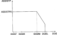
Fig. 6 is the ASSISTP figure that is used in Fig. 5 program;
Fig. 7 is a diagram of circuit of carrying out traction motor overhead control program;
Fig. 8 is a diagram of circuit of carrying out required electrical motor output decision procedure;
Fig. 9 represents to judge the RUNRST table of automobile running resistance;
Figure 10 represents to judge the MOTORPOWER figure of required electrical motor output;
Figure 11 A is the diagram of circuit of operating motor output decision procedure;
Figure 11 B is the further part of Figure 11 A flow process;
Figure 12 carries out deceleration regeneration subroutine subprogram diagram of circuit, and the S65 step of this program in Figure 11 B carried out;
Figure 13 is a diagram of circuit of carrying out the transmission control program;
Figure 14 A is used to explain the curve that the best rotative speed mode of traction motor is set;
Figure 14 B is used to explain the curve that the best rotative speed mode of traction motor is set;
Figure 15 is a diagram of circuit of carrying out engine overhead control program;
Figure 16 is a subroutine flow chart of carrying out engine working condition decision procedure, and the S132 step of this program in Figure 15 carried out.
The present invention is described in detail the accompanying drawing of referential expression embodiment.
At first referring to Fig. 1, it is the layout sketch of the actuating device of embodiment of the invention hybrid automobile and control setup thereof (having saved sensor, element that actuating device is relevant with other at this).
As shown in the figure, combustion engine 1 (hereinafter to be referred as engine) drives axle drive shaft 2 rotatably, gives drive wheel 5 to drive drive wheel 5 rotatably by driving device 4 transmitting torques.Traction motor 3 is installed on the axle drive shaft 2, but makes the former the direct drive latter rotate.Traction motor 3 is not only as the primary mover of boosting engine 1, and as an electrical generator, part automobile kinetic energy from rotating driveshaft 2 is transformed into electric energy produces actification, and the output electric energy, by power drives unit 13 (hereinafter to be referred as PDU) storage battery 14 is charged.Traction motor 3 is controlled its operation by the control signal that receives by PDU13.
Control system comprises the electronic control unit 11 (hereinafter to be referred as " ENGECU ") of Control Engine 1, the electronic control unit 12 (hereinafter to be referred as " MOTECU ") of control traction motor 3, the electronic control unit 16 of the electronic control unit 15 (hereinafter to be referred as " BATECU ") of control storage battery 14 and control driving device 4 (hereinafter to be referred as " T/MECU).These ECU by data bus 21 interconnect and transmit mutually the data of institute's detecting parameter, about the information etc. of sign.
Fig. 2 is engine 1, ENGECU11 and external equipment associated therewith.What be connected to the engine cylindrical region is a suction pipe 102 that is loaded into flow regulating valve 103.Flow regulating valve opening (θ TH) sensor 104 is connected with flow regulating valve 103, and the electric signal of the flow regulating valve opening θ TH that the generation expression detects also offers ENGECU11.Flow regulating valve 103 is line driving (DBW), is connected to throttle actuator 105, makes valve opening θ TH be subjected to electric control.Its operation of signal control that throttle actuator 105 is sent by ENGECU.
Fuel injection valve 106 (one of them only is shown) is inserted in the suction pipe 102, and suction pipe 102 also is partial to the upstream of its corresponding transfer valve slightly between engine 1 and flow regulating valve 103, do not mark transfer valve among the figure.Fuel injection valve 106 is connected with petrolift through pressure regulators, and is electrically connected with ENGECU11, the signal control that the timing of cycle of valve open and valve open is sent.Petrolift and pressure regulator are all not shown among the figure.
On the other hand, suction pipe absolute pressure (PBA) sensor 108 is arranged to through conduit 107 on adjacent flow regulating valve 103 downstream positions and 102 inner linking to each other of suction pipe, the electric signal of absolute pressure (PEA) in ENGECU11 provides the suction pipe of representing to detect 102.
Input air temperature (TA) sensor 109 is inserted into the suction pipe 102 that is positioned at conduit 107 downstreams, and the electric signal of the input air temperature (TA) that detects of expression is provided to ENGECU11.Can be positioned in the cylindrical region of engine 1 by engine refrigerant temperature (TW) sensor 110 that thermally dependent resistor or analogue are made, the electric signal of the engine refrigerant temperature TW that expression detects is provided to ENGECU11.
Engine speed (NE) sensor 111 be arranged to the camshaft of engine 1 or bent axle to relation of plane, camshaft and bent axle all do not mark.Whenever crankshaft revolution is crossed 180 degree, engine speed (NE) sensor 111 produces a pulse (hereinafter referred to as " TDC signal impulse ") at the crank angular position that presets of each cylinder.The TDC signal impulse offers ENGECU11.
Simultaneous oxidation reduction catalyst 115 is installed in the cylindrical region bonded assembly freeing pipe 114 with engine 1, to purify toxic substance, and as HC, CO and NO
xLinear output type air-fuel ratio sensor (hereinafter referred to as " LAF sensor ") 117 is installed in the freeing pipe 114 that is arranged in simultaneous oxidation reduction catalyst 115 upstreams.LAF sensor 117 provides the electric signal that roughly is directly proportional with oxygen concentration in the discharge gas to ENGECU11.LAF sensor 117 can be surveyed air-to-fuel ratio the compound that offers engine 1 in from rareness to the wide range that is rich in.
Simultaneous oxidation reduction catalyst 115 has a catalyst temperature (TCAT) sensor 118, and it passes to ENGECU11 with the output signal of the catalyst temperature T CAT that expression detects.In addition, the automotive speed sensor 119 of detection running automobile moving velocity VCAR all is connected with ENGECU11 with the accelerator opening sensor 120 that the accelerator pedal that detection is sent by chaufeur moves (hereinafter referred to as " accelerator opening ") θ AP, and the signal of expression car speed VCAR that detects and the accelerator opening θ AP that detects all offers ENGECU11.
ENGECU11 comprises an input circuit that does not mark, this circuit has from the waveform shaping signal of each sensor input, the voltage level of sensor output signal is moved on to a predetermined level and the analog signal conversion of simulation output transducer output is become effects such as digital signal, ENGECU11 also comprises a central process unit not marking (below be called " CPU "), the memory cell of each executive routine that storage is carried out by CPU and result of calculation thereof etc., one to the output circuit of fuel injection valve 106 output drive signals and light-up plug 113 etc.The structure of each of remaining ECU is substantially similar to ENGECU11.
Fig. 3 is traction motor 3, PDU13, storage battery 14, MOTECU12 and BATECU15 bonded assembly details drawing.
The current/voltage sensor 204 that alinement is electrically connected between PDU13 and storage battery 14 is surveyed the voltage and the outflow of storage batterys 14 mouths or is flow to the electric current of storage battery 14, and the output signal of the voltage and current that expression is detected offers BATECU15.
Fig. 4 is the connection diagram of driving device 4 and T/MECU16.Driving device 4 is speed change sensing devices, has arrangement to survey the tachogen 301 and 302 of driving device 4 drive shaft speed ND and output speed NM thereon, and it passes to T/MECU16 with the signal that expression elicites parameter.T/MECU16 is according to the calculated signals change gear ratio GR of sensor 301 and 302 outputs.In addition, driving device 4 also has a drive actuator 303 of settling on it, through drive actuator 303 by operation from the signal control driving device of T/MECU16.
Fig. 5 is such as the program of carrying out boosting/regeneration decision process in a preset time interval by BATECU15.
At first, calculate accumulated discharge value BATTDISCH and accumulative total charge value BATTCH in the S1 step.More particularly, current/voltage sensor 204 is surveyed the electric current and the received current (charging current) that flows to storage battery 14 from storage battery 14 outputs, and in the aggregate-value that whenever calculates the former (BATTDISCH) of executive routine and the latter's value (BATTCH).In the present embodiment, suppose accumulated discharge value BATTDICH be on the occasion of, accumulative total charge value BATTCH is a negative value.When traction motor 3 begins engine 1 boosting (in the S49 of Figure 11 A step), BATTDISCH resets with the accumulated discharge value, and when beginning regenerative electric energy by traction motor (the S73 step of Figure 11 B) will add up charge value BATTCHG and reset.
In following step S2, the depth of discharge DOD of calculating accumulator 14.Especially, if BATTFULL represents the electric capacity of storage battery 14, i.e. the electric weight that storage battery can discharge when storage battery is in fully charged state, then can utilize down establish an equation (1) to calculate depth of discharge DOD:
DOD=(BATTDISCH+BATTCH)/BATTFULL …(1)
Therefore, the dump energy BATTREM in the storage battery 14 can be calculated residual electricity dose rate RREM=BATTREM/BATTFULL=1-DOD by equation BATTREM=BATTFULL-(BATTDISCH+BATTCH).
In step S3, judge charging permission flag FDISCH, when being made as " 1 ", 14 discharges of expression storage battery.If keep FDISCH=1, whether then in the S9 step, judge depth of discharge DOD less than predetermined reference value DODL, this reference value is corresponding to the lower limit that stores electric weight in the storage battery 14.If keep DOD 〉=DODL, promptly the dump energy BATTREM in the storage battery 14 is little, then is made as " 0 " at the step S11 permission flag FDISCH that will discharge, thereby forbids the discharge of storage battery 14, terminator subsequently.
If keep DOD<DODL at step S9, then the depth of discharge DOD according to step S10 revises ASSISTP figure, to determine the discharge rate ASSISTP of permission.As for example ASSISTP figure that is provided with shown in Figure 6, make up to depth of discharge DOD reach one corresponding to storage battery 14 in the predetermined reference value DODM of electrically-charged intermediate quantity, discharge permission amount ASSISTP just is made as a predetermined fixed value ASSISTP0, and when depth of discharge DOD is in predetermined reference value DODM to the scope of predetermined reference value DODL the time, the ASSISTP value is made as the smaller value that increases with depth of discharge DOD.
In step S12 subsequently, judge whether boosting permission flag FASSIST is " 1 ", when being set at 1, but expression traction motor 3 boosting engines 1 provide torque to drive wheel 5.If keep FASSIST=1, then judge at step S13 whether the accumulated discharge value is equal to or greater than the discharge rate ASSISTP of permission.If keep BATTDISCH<ASSISTP, then program is ended immediately, promptly continue the boosting of 3 pairs of engines 1 of permission traction motor, if and BATTDISCH 〉=ASSISTP, then boosting permission flag FASSIST is set and is " 0 " in the S14 step, thereby the boosting of forbidding traction motor 3, then terminator.
S13 and S14 step make avoids the excessive possibility that becomes of storage battery 14 chargings, because when accumulated discharge value BATTDISCH was equal to or greater than the discharge rate ASSISTP of permission, the boosting of traction motor 3 was under an embargo.
On the other hand, if keep FASSIST=0 in the S12 step, mean that promptly the boosting of traction motor 3 is not licensed, judge in the S16 step then whether boosting execution sign FASSISTON is " 1 ", when sign FASSISTON was made as 1, the boosting of traction motor 1 was being carried out in expression.If keep FASSISTON=1, terminator immediately then, and if keep FASSISTON=0, then be made as " 1 ", subsequently terminator at S17 step boosting permission flag FASSIST.
If keep FDISCH=0 in the S3 step, mean that promptly storage battery 14 mustn't discharge, then whether judge depth of discharge DOD less than predetermined reference value DODR in the S14 step, when being equal to or less than predetermined reference value DODR, but the discharge regime of storage battery can recover (see figure 6).If keep DOD 〉=DODR, then program stops immediately, continue to forbid the discharge of storage battery 14, if keep DOD<DODR and pass through regeneration, then be made as " 1 ", and judge that in the S6 step depth of discharge DOD is whether less than the expression storage battery 14 predetermined reference value DODF (see figure 6) of full-charge state almost at the S5 step permission flag FDISCH that will discharge.If keep DOD 〉=DODF, mean that promptly storage battery 14 is not charged fully, then charging permission flag FCH is set and is " 1 ", thereby allow storage battery 14 charge or discharge in the S8 step.On the other hand,, mean that promptly storage battery 14 is almost charged fully, then charging permission flag FCH is set and is " 0 ", thereby forbid storage battery 14 charging, terminators subsequently in the S7 step if keep DOD<DODF.
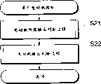
Fig. 7 is a program of carrying out the traction motor control process, is carried out in the preset time interval by MOTECU12.This program comprises two steps: step S21, the output decision process (subprogram shown in Figure 8) that operating motor is required; Step S22, operating motor output decision process (subprogram shown in Figure 11 A and the 11B).
Fig. 8 is the subprogram of the required output decision process of electrical motor, at first, in the S31 step, detection engine rotational speed N E and flow regulating valve opening θ TH (or alternately accelerator opening θ AP).Then, in the S32 step, according to these parameter value corrections ENGPOWER figure that detects, to determine required output ENGPOWER, i.e. the required engine output of automobile driver.
In S33 step subsequently, according to car speed VCAR modified R UNRST table, determine the resistance to motion RUNRST of automobile, i.e. the resistance that is subjected to during running car.The setting of RUNRST table for example as shown in Figure 9, when car speed VCAR increased, resistance to motion RUNRST was made as high value.Then, in the S34 step, calculate extra output EXPOWER by from the required output of engine ENGPOWER, deducting resistance to motion RUNRST.In above judgement and calculating, engine required output ENGPOWER and resistance to motion RUNRST all use watt (W) to calculate.
In step S35 subsequently, revise MOTORPOWER figure according to engine speed NE and extra output EXPOWER, to judge the required output (MOTORPOWER) of electrical motor.The big work area of EXPOWER is promptly additionally exported in zone in Figure 10 more than the L curve, and the required output of electrical motor MOTORPOWER is made as on the occasion of (MOTORPOWER>0), thereby allows traction motor 3 boostings.On the other hand, zone in Figure 10 below the L curve, promptly extra output EXPOWER be made as one little on the occasion of or the work area of negative value in, the required output of electrical motor MOTORPOWER is made as a negative value, (MOTORPOWER<0), thereby allow traction motor 3 regenerative electric energies.As shown in figure 10, curve L progressively raises along with the increase of engine speed NE, this means when rotational speed N E is higher, the required output of electrical motor MOTORPOWER with respect to bigger extra output valve EXPOWER be made as one on the occasion of, promptly allow the boosting of traction motor 3.
As mentioned above, process according to Fig. 8, by from the required output of engine ENGPOWER, deducting the extra output EXPOWER of resistance to motion RUNRST computing engines, and determine the output MOTORPOWER that electrical motor is required according to extra output EXPOWER and engine speed NE.
Figure 11 A and 11B are the subprogram detail drawings of the electrical motor output decision process of S22 step in the execution graph 7.
At first, judge that in the S41 step whether the required output of electrical motor MOTORPOWER is greater than " 0 ".If keep MOTORPOWER, then judge in the S42 step whether boosting execution sign FASSISTON is " 1 " greater than " O ".If FASSISTON=1, promptly mean and carry out 3 pairs of engine 1 boostings of traction motor, then program jumps to the S50 step, if and FASSISTON=0, promptly mean and do not carry out 3 pairs of engine 1 boostings of traction motor, then judge that in the S43 step whether the variable quantity DTH that elicites at flow regulating valve opening QTH is greater than predetermined value DTHREF (greater than 0).
If keep DTH≤DTHREF, then program jumps to the S51 step, and if DTH>DTHREF, promptly meaning needs engine 1 to be accelerated, and then in the S45 step boosting is set to carry out sign FASSISTON and be " 1 ", and then carries out the program of step S47.
In step, all regeneration signs (being made as " 1 " when carrying out the regeneration of traction motor 3 electric energy) promptly run at a constant speed regeneration sign FCRUREG at S47, and neutral regeneration sign FIDLEREG and deceleration regeneration sign FDREG all are made as " 0 ".Then, in the S48 step pulsation is set and weakens sign FREDDNE for " 0 ", when this sign was set to " 1 ", expression was carried out torque pulsation and is weakened process (step S70 among Figure 11 B), and in S49 step accumulated discharge value BATTDISCH is set and is " 0 ", proceed the S50 step subsequently.
In the S50 step, judge whether boosting permission flag FASSIST is " 1 ".If keep FASSIST=1, then program jumps to the S53 step, and if FASSIST=0, then program continuation step S51.
In step, boosting is carried out sign FASSISTON and is made as " 0 " at S51, and the required output of electrical motor MOTORPOWER is made as " 0 " in the S52 step.Then, program proceeds to step S53, and electrical motor output OUTPUTPOWER is set to the required output of electrical motor MOTORPOWER, terminator subsequently there.
According to the step of above S42 to S52, as long as keep the required output of electrical motor MOTORPOWER greater than 0, the drive system of hybrid automobile is just controlled by following mode:
1) even keep MOTORPOWER>0, do not carry out the boosting of 3 pairs of engines 1 of traction motor, unless engine needs to quicken (S43, S51 and S52) yet; With
2) when engine need quicken, if allow the tilt operation of engine 1 and the boosting of 3 pairs of engines 1 of traction motor, then the drive system of hybrid automobile can be utilized the boosting operation of 3 pairs of engines 1 of traction motor, the feasible air-to-fuel ratio of the compound of engine 1 that is supplied to is controlled at a fixing deviant or the deviant according to the boosting amount of 3 pairs of engines 1 of traction motor, if and do not allow the tilt operation of engine 1 and the boosting of 3 pairs of engines 1 of traction motor, then the drive system of hybrid automobile can be utilized the boosting work of 3 pairs of engines 1 of traction motor, make the air-to-fuel ratio of compound be controlled at a normal value or a stoichiometric ratio (step S43, S45, and S50).
If keep MOTORPOWE≤0 in the S41 step, then program is carried out the S61 step among Figure 11 B, judges there whether the temperature T D of the protective resistance of PDU13 is higher than predetermined value TDF.If TD>TDF, the temperature of then worrying traction motor 3 driving circuits is too high, to such an extent as to traction motor can not carry out the regeneration of electric energy, make all regeneration be identified at S63 step and be made as " 0 ", thereby forbid regeneration, and in the S71 step, the required output of electrical motor MOTORPOWE is made as " 0 ", carries out the step S53 among Figure 11 A subsequently.It is too high to make that like this temperature of PDU driving circuit 13 can not become.
On the other hand, if keep TD≤TDF, then judge in the S62 step whether the charging permission flag is " 1 " in the S61 step.If FCH=0 does not promptly allow battery charge or discharge, then program proceeds to the S63 step, forbids regeneration.This can prevent storage battery 14 charging thermal loss and other inconvenience excessive, the excessive PDU13 that causes because storage battery 14 charges.
If keep FCH=1 at step S62, show that the charging of storage battery 14 allows, judge regeneration sign FCRUREG in step 72, whether any one among FIDLEREG and the FDREG is " 1 ".If arbitrary being designated " 1 " wherein, program jumps to step S64, and if all regeneration is designated " 0 ", then be set as " 0 " at step S73 accumulative total charge value BATTCHG, after this program enters step S64.
At step S64, whether the sign of judge slowing down FDEC is " 1 ", when it is made as " 1 ", shows the deceleration (see among Figure 16 step S144 to S146) of requirement engine 1.If keep FDEC=1, then finish deceleration regeneration process (by carrying out subprogram as shown in Figure 12) at step S65, program enters into step S53 then.
If keep FDEC=0, this shows the deceleration that does not require engine 1, judges at step S66 whether unloaded sign FIDLE is " 1 ", when it is made as " 1 ", shows that engine 1 is unloaded (sees among Figure 16 step S151 to S155).If keep FIDLE=0, show that engine 1 is not unloaded, finish running at a constant speed regenerative process at step S67, program enters into step S53 then.
In running at a constant speed regenerative process, run at a constant speed regeneration sign FCRUREG and be set as " 1 ", according to engine speed NE and extra output EXPOWER, run at a constant speed regeneration spirogram (not shown) and be resumed then, determined one to run at a constant speed regeneration amount CRURGE thus.Then, the output MOTORPOWER of electrical motor requirement is set as the definite regeneration amount that runs at a constant speed CRURGE.
If in step S66, keep FIDLE=1, judge that at step S68 rotating pulsation identifies whether FDNE is " 1 ", when it is made as " 1 ", shows that the speed ripple of engine 1 is very big.If keep FDNE=1, finish the pulsation process that subtracts of torque at step S70, and if keep FDNE=0, then finish unloaded regenerative process at step S69, program enters into step S53 then.
Subtracting in the pulsation process of torque, the required output MOTORPOWER of electrical motor is judged as the value that reduces the engine speed pulsation.In the regenerative process of zero load, unloaded regeneration sign FIDLEREG is set as " 1 ", and according to the depth of discharge DOD of storage battery 14, unloaded regeneration amount IDLEREG is determined.Then, the required output MOTORPOWER of electrical motor is set as the regeneration amount IDLEREG of definite zero load.
As mentioned above, electrical motor output decision process according to Figure 11 A and 11B, based on the required output MOTORPOWER of the electrical motor of in Fig. 8 process, judging, and the state that depends on the boosting permission flag FASSIST that establishes according to dump energy in the storage battery 14 and the permission flag FCH that charges, traction motor 3 can be made as one of following pattern selectively, a kind of boost mode, traction motor 3 boosting engines 1 in this pattern are (by step S45 to S50, and S53), a kind of regeneration mode, electric energy regeneration is performed (by step S65 in this pattern, S67, and S69) and a zero output pattern, traction motor 3 does not produce output (by step S52 and S71) in this pattern.This makes might control traction motor 3 so that carry out the boosting of engine 1 and the regeneration of electric energy with a kind of suitable manner, the torque of hybrid automobile drive system generation performance and oil-saving effect all can be improved thus, and keep dump energy sufficient in the storage battery 14 simultaneously.
Figure 12 represents a subprogram that is used to finish the deceleration regeneration process that step S65 is performed in Figure 11 B.
At first, carry out sign FASSISTON in step S111 boosting and be set as " 0 ", and subtract pulsation sign FREDDNE at step S112 and be set as " 0 ".Then, the required output MOTORPOWER of electrical motor of the judgement of the step 35 among Fig. 8 is used as step S113.That is to say, between deceleration period, in the MOTORPOWER of Figure 10 figure, keep the zone of EXPOWER<0 to be resumed, and the numerical value MOTORPOWER that obtains is adopted by former state.
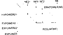
Then, with reference to figure 14A and 14B (zone that keeps EXPOWER<0), will the method for the mapping value of setting MOTORPOWER figure be described.In these figure, every solid line is represented a regeneration output limit REGLMT (NE) of traction motor 3, and dotted line is represented the energy BRKPOWER (NE) of engine brake loss.(NE) of these parameters shows that these parameters are functions of engine speed NE.Determine regeneration output limit REGLMT (NE) so that itself and the proportional increase of engine speed NE in engine speed NE is lower than the scope of preset value NE0 according to the standard of traction motor 3, and in the NE value is equal to or higher than the scope of preset value NE0, be a fixing value.When engine speed NE increased, the energy BRKPOWER (NE) of engine brake loss increased.
If (the NE of the coordinate points among the figure, EXPOWER) expression, at coordinate points (NE1, EXPOWER11) mapping value is set to MOTORPOWER=EXPOWER11-BRKPOWER (NE1), and (NE1, mapping value EXPOWER1) is set to MOTORPOWER=EXPOWER1-BRKPOWER (NE1)=REGLMT (NE1)-BRKPOWER (NE1) in coordinate points.In the zone that keeps NE=NE1 and EXPOWER>EXPOWER1, this regional mapping value is set to MOTORPOWER=REGLMT (NE1)-BRKPOWER (NE1).
(NE2, mapping value EXPOWER21) is set to MOTORPOWER=EXPOWER21-BRKPOWER (NE2) in coordinate points.In the zone that keeps NE=NE2 and EXPOWER>EXPOWER0, the mapping value in this zone is set to MOTORPOWER=REGLMT (NE2)-BRKPOWER (NE2)=EXPOWER0-BRKPOWER (NE2).
Next step is set to " 1 " at step S114 deceleration regeneration sign FDREG, and at subsequently step S115, the rotational speed N EOPT an of the best is calculated in the following manner:
1) in Figure 14 A and 14B, (NE1 EXPOWER1), keep EXPOWER1=REGLMT (NE1), so NEOPT is set as NE1 if the current engine operating conditions is corresponding to coordinate points.
2) (NE1, EXPOWER11), output becomes maximum if NE=NE11 then regenerates, so NEOPT is set as NE11 if the current engine operating conditions is corresponding to coordinate points.
3) (NE1, EXPOWER12), output becomes maximum if NE=NE12 then regenerates, so NEOPT is set as NE12 if the current engine operating conditions is corresponding to coordinate points.
4) (NE1, EXPOWER13), output becomes maximum if NE=NE0 then regenerates, so NEOPT is set as NE0 if the current engine operating conditions is corresponding to coordinate points.
5) (NE2, EXPOWER21), output becomes maximum if NE=NE21 then regenerates, so NEOPT is set as NE21 if the current engine operating conditions is corresponding to coordinate points.
6) (NE2, EXPOWER22), output becomes maximum if NE=NE0 then regenerates, so NEOPT is set as NE0 if the current engine operating conditions is corresponding to coordinate points.
Next step, the currency of step S116 computing engines rotational speed N E and the poor SNE between optimum speed NEOPT (=NEOPT-NE), then stop current program.
As mentioned above, based on the electrical motor output OUTPUTPOWER that is calculated by Figure 11 A and 11B process, MOTECU12 controls PDU13, controls the operation mode (boost mode, regeneration mode, zero output pattern) of traction motor 3 thus.
Figure 13 represents to control the program of driving device 4, and for example, at interval interior at the fixed time this program is carried out by T/MECU16.
At first,, take out the various controlled variable that detect,, and, calculate the base value RBASE of change gear ratio based on accelerator opening θ AP and the vehicle velocity V CAR of step S122 as accelerator opening θ AP and vehicle velocity V CAR in step 121.At next step S123, based on the speed discrepancy SNE that the step S116 of Figure 12 calculates, drive shaft speed NM that detects (or vehicle velocity V CAR) and basic change gear ratio RBASE calculate a desirable change gear ratio RK.Calculate desirable change gear ratio RK and equal 0 so that speed discrepancy SNE becomes.If even also can be because of speed discrepancy SNE can not be made as SNE=0 too greatly by changing change gear ratio, the RK value be set as such value and therefore can controls by changing change gear ratio so that the SNE value becomes minimum.In addition, if do not carry out the deceleration regeneration process, rotating speed difference SNE is set as " 0 ".
Next step, step S124 calculate desirable change gear ratio RK and the change gear ratio RG that detects between difference SR (=RK-GR) and calculate the operational ton of drive actuator according to change gear ratio difference SR.Then, the operational ton of the drive actuator 303 of Ji Suaning is set in the output register of step S125 like this, then finishes present procedure.
As mentioned above, when according to Figure 12 and Figure 13 process execution deceleration regeneration, the regeneration output of calculating traction motor 3 becomes maximum optimum speed (engine speed=motor speed) NEOPT, and the change gear ratio of control driving device 4 is so that the optimum speed NEOPT that motor speed becomes and equals to calculate, and the kinetic energy that produces between the deceleration period of automobile can be assembled effectively and is electric energy whereby.In addition, because according to electrical motor regeneration output limit REGLMT calculating optimum rotational speed N EOPT, can avoid the extra variation of the overheated and change gear ratio of traction motor.
Determine the required output MOTORPOWER of electrical motor during deceleration regeneration according to engine speed NE that detects and extra output EXPOWER.Therefore, even do not equal optimum speed NEOPT when actual engine speed NE does not become, the MOTORPOWER value also can be set to the value of a suitable actual engine rotational speed N E.
Next step, the engine of being carried out by ENGECU11 is controlled at and describes below.Figure 15 shows that it is performed for the program of whole engine control in such as default time gap.
At first, different engine operation parameters, be detected at step S131 as engine speed NE and suction pipe absolute pressure PBA, the operating conditions decision process of order execution in step S132 then, the fuel supply control process of step S133, the point of ignition control process of step S134 and at the DBW of step S135 control process (by the flow regulating valve opening control process of throttle actuator 105).
Figure 16 represents to be used for to finish a subprogram of the operating conditions decision process of Figure 15 step S132.
At step S141, judge in the flow regulating valve opening θ TH that detects (current θ TH value-θ TH value) before this variable quantity DTH whether greater than be scheduled on the occasion of DTHA.If keep DTH>DTHA, quicken sign FACC at step S143 and be set as " 1 ", and if keep DTH≤DTHA, quicken sign FACC at step S142 to be set as " 0 ", program enters step S144 then.
At step S144, whether the variable quantity DTH of judgement in flow regulating valve opening θ TH be less than predetermined negative value DTHD.If keep DTH<DTHD, be set as " 1 " at the step S146 sign FDEC that slows down, and if keep DTH 〉=DTHA, be set as " 0 " in the step S145 sign of slowing down, program enters step S147 then.
At step S147, judge whether engine coolant temperature T W is equal to or greater than predetermined value TWREF.If keep TW>TWREF, judge further at step S148 whether catalyst temperature T CAT is equal to or greater than predetermined reference value TCATREF.If keep TW<TWREF, or keep TCAT<TCATREF, tilt to identify FLEAN at step S150 and be set as " 0 " to stop tilt operation of engine 1 at step S148 at step S147.On the other hand, if keep TW 〉=TWREF and keep TCAT 〉=TCATREF simultaneously, tilt to identify FLEAN at step S149 and be set as " 1 " to allow tilt operation of engine 1 at step S148 at step S147.
At step S151 thereupon, judge whether vehicle velocity V CAR is equal to or less than 0.If keep VCAR≤0, this shows that automobile is in halted state, then judges at step S152 whether driving device 4 is in neutral gear.If driving device 4 is in neutral gear, judge at step S153 whether accelerator opening θ AP is equal to or less than predetermined quiescent value θ IDLE.If all are sure (YES) for step S151 to the problem of S153, judge that then engine is unloaded, therefore be set as " 1 " at the unloaded sign of step S154 FIDLE, if and all are (NO) that negates for step S151 to the problem of S153, judge that then engine is not unloaded, therefore be set as " 0 " at the unloaded sign of step S155 FIDLE, program enters step S156 then.
At step S156, judge whether the variation delta NE (the current NE value of Δ NE=-value) before this of engine speed NE is equal to or greater than preset value Δ NEREF.If keep Δ NE 〉=Δ NEREF, rotate pulsation sign FDNE at step S157 and be set as " 1 ", and if keep Δ NE<Δ NEREF, rotate pulsation sign FDNE at step S158 to be set as " 0 ", thereupon termination routine.
In the fuel supply control process that Figure 15 step S133 carries out,, be supplied to the fuel of engine to be interrupted if keep slowing down sign FDEC=1.On the other hand, if keep FDEC=0, then according to the working condition of engine such as the rotational speed N E and the suction pipe absolute pressure PBA of engine, the opening of valves of valve opening time that computing fuel shooting valve 106 is opened and fuel injection valve 106 regularly and is carried out the supply control of fuel according to the value that calculates.
In the ignition timing control that step S134 carries out, calculate ignition timing according to the engine operation condition, as engine speed NE and suction pipe absolute pressure PBA, and according to the value execution ignition timing control of calculating.
In the DBW control that step S135 carries out, according to the ideal value of accelerator opening θ AP calculating flow regulating valve opening θ TH, engine speed NE, or the like, and flow regulating valve opening θ TH is controlled to the ideal value of calculating.
The present invention is not limited to the above embodiments, but can be accomplished by various improvement and variation.For example, as electrical energy storage device, the cond with big electrostatic capacity can be used to combination or replace storage battery 14 to use.
In addition, the present invention also can be applied to an engine, replaces the flow regulating valve 103 of so-called DBW type, and this engine adopts the flow regulating valve of the common type that connects with the accelerator pedal mechanical type.
In addition, though in the present embodiment, if keep FCH=0; if promptly do not allow battery charge; if or the temperature T D of PDU13 protective resistance is higher than preset value TDF, electric energy regeneration is under an embargo (regeneration amount=0) (step S61, S62, S63 and S71 among Figure 11 B), and this is hard-core.Perhaps, regeneration amount can be set as very little value.
Again in addition, driving device 4 automatic driver that also can be able to be changed change gear ratio in mode step by step replaces.In this case, the gear Be Controlled is so that motor speed is assumed to one near the value of optimum speed NEOPT, so that actual speed does not exceed the rotational speed N E0 among Figure 14.
Claims (8)
1. the control setup of a hybrid automobile, wherein, two driving automobiles comprise drive wheel, combustion engine, by the axle drive shaft of driven by engine, with the described axle drive shaft of electric energy direct drive and have and convert the kinetic energy of axle drive shaft to the traction motor of the regeneration function of electric energy, drive wheel that one is installed in automobile and the driving device between engine and the traction motor and one to traction motor transmission of electric energy and electrical storage device that the electrical power storage of traction motor output is got up, control system comprises:
The computer device of desirable output, the ideal output of calculating traction motor according to the deceleration situation of automobile;
The optimum speed computer device according to the regeneration output limit of ideal output that is calculated by described desirable output computer device and described traction motor, calculates the optimum speed of traction motor, and traction motor provides maximum regeneration output under this rotating speed; With
The change gear ratio control setup, the change gear ratio of control driving device makes the rotating speed of traction motor equal optimum speed.
2. control setup as claimed in claim 1 is characterized in that described desirable output computer device comprises the computer device of the required output of chaufeur, comprises that with basis the engine mode of operation of engine speed calculates the required output of chaufeur of described automobile; The resistance to motion computer device calculates resistance to motion with the travel conditions according to automobile; Additionally export computer device with engine, with according to the required output of chaufeur and the extra output of resistance to motion computing engines, described desirable output computer device calculates the ideal output of traction motor according to the extra output of engine.
3. control setup according to claim 2, it is characterized in that the regeneration output limit of described optimum speed computer device according to the revolution speed calculating traction motor of engine, and, calculate the optimum speed of traction motor according to the ideal output of traction motor and the output limit of regenerating.
4. control setup according to claim 1, it is characterized in that the rotating speed direct proportion ground increase of being arranged so that in engine speed is lower than the scope of predetermined value of described regeneration output limit, and in engine speed is equal to or greater than the scope of predetermined value, be made as fixed value with engine.
5. according to claim 3 or 4 described control setups, it is characterized in that described change gear ratio control setup controls the change gear ratio of described driving device according to the difference between engine speed and the optimum speed, make described difference minimum.
6. control setup according to claim 5, it is characterized in that described automobile comprises acceleration pedal, contain driven shaft drive, the described change gear ratio control setup of device that contains the basic change gear ratio of moving velocity computing gear of the acceleration amount of with good grounds acceleration pedal and automobile, this change gear ratio control setup is according to engine speed and optimum speed, difference between the rotating speed of driven shaft and the basic change gear ratio that calculated by described device is calculated desirable change gear ratio, and described change gear ratio control setup controls to described change gear ratio the desirable change gear ratio of calculating.
7. according to any one described control setup in the claim 1 to 4, it is characterized in that comprising dump energy computer device that calculates dump energy in the electrical storage device and the electrical motor output device for limiting that limits traction motor output according to the dump energy that the dump energy computer device calculates.
8. according to any one described control setup in the claim 1 to 4, it is characterized in that described driving device is a kind of variable-speed drive.
Applications Claiming Priority (2)
| Application Number | Priority Date | Filing Date | Title |
|---|---|---|---|
| JP149727/96 | 1996-05-22 | ||
| JP14972796A JP2843883B2 (en) | 1996-05-22 | 1996-05-22 | Control device for hybrid vehicle |
Publications (2)
| Publication Number | Publication Date |
|---|---|
| CN1169378A CN1169378A (en) | 1998-01-07 |
| CN1079056C true CN1079056C (en) | 2002-02-13 |
Family
ID=15481498
Family Applications (1)
| Application Number | Title | Priority Date | Filing Date |
|---|---|---|---|
| CN97113243A Expired - Fee Related CN1079056C (en) | 1996-05-22 | 1997-05-22 | Control system for hybrid automobile |
Country Status (6)
| Country | Link |
|---|---|
| US (1) | US5942879A (en) |
| EP (1) | EP0808735B1 (en) |
| JP (1) | JP2843883B2 (en) |
| KR (1) | KR100261956B1 (en) |
| CN (1) | CN1079056C (en) |
| DE (1) | DE69705771T2 (en) |
Cited By (2)
| Publication number | Priority date | Publication date | Assignee | Title |
|---|---|---|---|---|
| US7301245B2 (en) | 2002-01-30 | 2007-11-27 | Toyota Jidosha Kabushiki Kaisha | Control system for a vehicle power supply and control method thereof |
| CN100435450C (en) * | 2004-10-05 | 2008-11-19 | 现代自动车株式会社 | Method for controlling regenerative braking of a belt-driven hybrid vehicle |
Families Citing this family (44)
| Publication number | Priority date | Publication date | Assignee | Title |
|---|---|---|---|---|
| JP2857666B2 (en) * | 1996-06-12 | 1999-02-17 | 本田技研工業株式会社 | Control device for hybrid vehicle |
| JP3096447B2 (en) * | 1997-09-17 | 2000-10-10 | 本田技研工業株式会社 | Control device for hybrid vehicle |
| US6020697A (en) * | 1997-11-14 | 2000-02-01 | Honda Giken Kogyo Kabushiki Kaisha | Hybrid vehicle |
| JP3401181B2 (en) * | 1998-02-17 | 2003-04-28 | トヨタ自動車株式会社 | Drive control device for hybrid vehicle |
| US6554088B2 (en) | 1998-09-14 | 2003-04-29 | Paice Corporation | Hybrid vehicles |
| JP3347080B2 (en) * | 1998-12-18 | 2002-11-20 | 本田技研工業株式会社 | Hybrid vehicle start determination device |
| JP3666727B2 (en) * | 1999-07-05 | 2005-06-29 | 本田技研工業株式会社 | Hybrid vehicle drive device |
| US6757597B2 (en) | 2001-01-31 | 2004-06-29 | Oshkosh Truck | A/C bus assembly for electronic traction vehicle |
| US7905813B2 (en) * | 1999-09-28 | 2011-03-15 | Borealis Technical Limited | Electronically controlled engine generator set |
| JP3542938B2 (en) * | 1999-10-29 | 2004-07-14 | 本田技研工業株式会社 | Hybrid vehicle control device |
| JP3506975B2 (en) * | 1999-10-29 | 2004-03-15 | 本田技研工業株式会社 | Hybrid vehicle control device |
| JP2001146121A (en) * | 1999-11-19 | 2001-05-29 | Toyota Motor Corp | Control device for hybrid vehicle with transmission |
| JP2001238303A (en) * | 2000-02-24 | 2001-08-31 | Mitsubishi Motors Corp | Regenerative controller of hybrid electric vehicle |
| JP3712910B2 (en) | 2000-03-23 | 2005-11-02 | トヨタ自動車株式会社 | Vehicle transmission control device |
| JP3700531B2 (en) * | 2000-04-05 | 2005-09-28 | スズキ株式会社 | Control device for hybrid vehicle |
| JP3768382B2 (en) * | 2000-05-22 | 2006-04-19 | 本田技研工業株式会社 | Control device for hybrid vehicle |
| JP4557402B2 (en) * | 2000-09-19 | 2010-10-06 | トヨタ自動車株式会社 | Vehicle drive control device |
| US7379797B2 (en) | 2001-01-31 | 2008-05-27 | Oshkosh Truck Corporation | System and method for braking in an electric vehicle |
| JP4029592B2 (en) * | 2001-09-05 | 2008-01-09 | 株式会社日立製作所 | Auxiliary drive device and automobile equipped with the same |
| JP3588090B2 (en) * | 2002-06-27 | 2004-11-10 | 本田技研工業株式会社 | Hybrid vehicle control device |
| US7395887B2 (en) * | 2004-12-23 | 2008-07-08 | Bosch Rexroth Corporation | Complementary regenerative torque system and method of controlling same |
| US7543454B2 (en) | 2005-03-14 | 2009-06-09 | Zero Emission Systems, Inc. | Method and auxiliary system for operating a comfort subsystem for a vehicle |
| US7600595B2 (en) | 2005-03-14 | 2009-10-13 | Zero Emission Systems, Inc. | Electric traction |
| JP4513751B2 (en) * | 2006-01-13 | 2010-07-28 | トヨタ自動車株式会社 | Hybrid vehicle and control method thereof |
| US7921945B2 (en) | 2006-02-21 | 2011-04-12 | Clean Emissions Technologies, Inc. | Vehicular switching, including switching traction modes and shifting gears while in electric traction mode |
| US8565969B2 (en) | 2007-04-03 | 2013-10-22 | Clean Emissions Technologies, Inc. | Over the road/traction/cabin comfort retrofit |
| JP5001566B2 (en) * | 2006-03-23 | 2012-08-15 | 三菱ふそうトラック・バス株式会社 | Electric vehicle control device |
| DE102006022384B4 (en) * | 2006-05-12 | 2020-11-19 | Robert Bosch Gmbh | Method for heating up or keeping an exhaust gas cleaning device of a vehicle warm |
| US7921950B2 (en) | 2006-11-10 | 2011-04-12 | Clean Emissions Technologies, Inc. | Electric traction retrofit |
| US8234031B2 (en) | 2007-02-22 | 2012-07-31 | Mack Trucks, Inc. | Hybrid vehicle energy management methods and apparatus |
| WO2008103174A1 (en) | 2007-02-22 | 2008-08-28 | Mack Trucks, Inc. | Hybrid vehicle auxiliary equipment energy management |
| JP4906164B2 (en) * | 2007-07-19 | 2012-03-28 | アイシン・エィ・ダブリュ株式会社 | Map display device, map display method, and computer program |
| JP5163000B2 (en) * | 2007-08-02 | 2013-03-13 | 日産自動車株式会社 | Regenerative control device for hybrid vehicle |
| JP5619627B2 (en) * | 2008-02-08 | 2014-11-05 | ボルボ テクノロジー コーポレイション | Method for operating hybrid vehicle and hybrid vehicle |
| MX2010009878A (en) | 2008-03-19 | 2010-09-28 | Zero Emission Systems Inc | Electric traction system and method. |
| US9758146B2 (en) | 2008-04-01 | 2017-09-12 | Clean Emissions Technologies, Inc. | Dual mode clutch pedal for vehicle |
| FR2945243B1 (en) * | 2009-05-11 | 2012-06-01 | Renault Sas | SYSTEM FOR CONTROLLING THE TORQUE TO THE WHEELS OF A VEHICLE EQUIPPED WITH AT LEAST ONE ELECTRIC MOTOR. |
| US9631528B2 (en) | 2009-09-03 | 2017-04-25 | Clean Emissions Technologies, Inc. | Vehicle reduced emission deployment |
| JP5316724B2 (en) * | 2011-03-23 | 2013-10-16 | トヨタ自動車株式会社 | Vehicle drive device |
| WO2013035294A1 (en) * | 2011-09-08 | 2013-03-14 | マツダ株式会社 | Hybrid automobile and engine in hybrid automobile, as well as specification setting method for motor generator |
| CN103129565A (en) * | 2011-11-24 | 2013-06-05 | 金鹰重型工程机械有限公司 | Hybrid power transmission system |
| CN102705088B (en) * | 2012-06-26 | 2015-11-25 | 上海三一重机有限公司 | The mine car of a kind of electric drive mine car transmission system controlling method and utilization the method |
| JP2017094829A (en) * | 2015-11-20 | 2017-06-01 | いすゞ自動車株式会社 | Hybrid vehicle and control method therefor |
| CN108773298A (en) * | 2018-06-08 | 2018-11-09 | 北京长城华冠汽车科技股份有限公司 | Control method, storage medium and the electric vehicle of violent acceleration pattern |
Citations (3)
| Publication number | Priority date | Publication date | Assignee | Title |
|---|---|---|---|---|
| US3923115A (en) * | 1971-10-29 | 1975-12-02 | Juergen Helling | Hybrid drive |
| US4165795A (en) * | 1978-02-17 | 1979-08-28 | Gould Inc. | Hybrid automobile |
| EP0710787A2 (en) * | 1994-11-04 | 1996-05-08 | Aisin Aw Co., Ltd. | Starting system with energy recovery for automotive vehicles |
Family Cites Families (11)
| Publication number | Priority date | Publication date | Assignee | Title |
|---|---|---|---|---|
| US4407132A (en) * | 1980-02-20 | 1983-10-04 | Daihatsu Motor Co., Ltd. | Control apparatus and method for engine/electric hybrid vehicle |
| US4305254A (en) * | 1980-02-20 | 1981-12-15 | Daihatsu Motor Co., Ltd. | Control apparatus and method for engine/electric hybrid vehicle |
| JPH05161216A (en) * | 1991-12-05 | 1993-06-25 | Honda Motor Co Ltd | Speed change controller for motor vehicle |
| JPH05229351A (en) * | 1992-02-19 | 1993-09-07 | Aisin Aw Co Ltd | Motor-driven device for vehicle |
| DE4217668C1 (en) * | 1992-05-28 | 1993-05-06 | Daimler Benz Ag | Method for controlling a hybrid drive that drives a vehicle |
| JP2897624B2 (en) * | 1993-11-25 | 1999-05-31 | 大同特殊鋼株式会社 | Purge gas supply device for tubing |
| JPH07150375A (en) * | 1993-11-25 | 1995-06-13 | Tokin Corp | Cleaning solution |
| JP3534271B2 (en) * | 1995-04-20 | 2004-06-07 | 株式会社エクォス・リサーチ | Hybrid vehicle |
| DE19623847A1 (en) * | 1995-06-16 | 1996-12-19 | Aisin Aw Co | Control of drive unit of hybrid vehicle with IC engine and motor-generator set with recuperative braking system |
| JP3171079B2 (en) * | 1995-07-24 | 2001-05-28 | トヨタ自動車株式会社 | Vehicle drive control device |
| US5637987A (en) * | 1995-12-18 | 1997-06-10 | General Motors Corporation | Regenerative vehicle launch |
-
1996
- 1996-05-22 JP JP14972796A patent/JP2843883B2/en not_active Expired - Fee Related
-
1997
- 1997-05-13 US US08/855,249 patent/US5942879A/en not_active Expired - Lifetime
- 1997-05-16 DE DE69705771T patent/DE69705771T2/en not_active Expired - Lifetime
- 1997-05-16 EP EP97108049A patent/EP0808735B1/en not_active Expired - Lifetime
- 1997-05-20 KR KR1019970019437A patent/KR100261956B1/en not_active IP Right Cessation
- 1997-05-22 CN CN97113243A patent/CN1079056C/en not_active Expired - Fee Related
Patent Citations (3)
| Publication number | Priority date | Publication date | Assignee | Title |
|---|---|---|---|---|
| US3923115A (en) * | 1971-10-29 | 1975-12-02 | Juergen Helling | Hybrid drive |
| US4165795A (en) * | 1978-02-17 | 1979-08-28 | Gould Inc. | Hybrid automobile |
| EP0710787A2 (en) * | 1994-11-04 | 1996-05-08 | Aisin Aw Co., Ltd. | Starting system with energy recovery for automotive vehicles |
Cited By (2)
| Publication number | Priority date | Publication date | Assignee | Title |
|---|---|---|---|---|
| US7301245B2 (en) | 2002-01-30 | 2007-11-27 | Toyota Jidosha Kabushiki Kaisha | Control system for a vehicle power supply and control method thereof |
| CN100435450C (en) * | 2004-10-05 | 2008-11-19 | 现代自动车株式会社 | Method for controlling regenerative braking of a belt-driven hybrid vehicle |
Also Published As
| Publication number | Publication date |
|---|---|
| JP2843883B2 (en) | 1999-01-06 |
| DE69705771T2 (en) | 2002-05-23 |
| DE69705771D1 (en) | 2001-08-30 |
| CN1169378A (en) | 1998-01-07 |
| JPH09310755A (en) | 1997-12-02 |
| US5942879A (en) | 1999-08-24 |
| EP0808735A1 (en) | 1997-11-26 |
| EP0808735B1 (en) | 2001-07-25 |
| KR970074123A (en) | 1997-12-10 |
| KR100261956B1 (en) | 2000-08-01 |
Similar Documents
| Publication | Publication Date | Title |
|---|---|---|
| CN1079056C (en) | Control system for hybrid automobile | |
| CN1124208C (en) | Control system for hybrid vehicle | |
| CN1105656C (en) | Control system for hybrid vehicle | |
| CN1074504C (en) | System and method for controlling generator for vehicle | |
| CN1298560C (en) | Mixed power automobile control system and its control method | |
| CN1280128C (en) | Diagnostic device of automobile electric motor | |
| CN1241765C (en) | Composite power vehicle and its control method | |
| CN1068836C (en) | Operation method for compound-power driven vehicle not running on track | |
| CN104787037B (en) | Control apparatus for series hybrid vehicle | |
| EP1193108A3 (en) | Method and apparatus for adaptive energy management of a hybrid electric vehicle | |
| CN105383311A (en) | Regenerative control device for hybrid vehicle | |
| JPH09284916A (en) | Controller for hybrid vehicle | |
| CN1927611A (en) | Engine starting control device for hybrid power vehicle | |
| CN101060255A (en) | Vehicle-use power generation control apparatus | |
| EP1093950A3 (en) | Control system for hybrid vehicles | |
| EP1225074A3 (en) | A hybrid electric vehicle having a selective zero emission mode, and method of selectively operating the zero emission mode | |
| EP1219492A3 (en) | Method and apparatus for adaptive control of hybrid electric vehicle propulsion | |
| CN105383482A (en) | Regenerative control device for hybrid vehicle | |
| CN1572564A (en) | Power output apparatus, method of controlling power output apparatus, and automobile with power output apparatus mounted thereon | |
| JPH0998515A (en) | Engine controller for hybrid vehicle | |
| CN101031460A (en) | Drive apparatus for hybrid vehicle and control method thereof | |
| EP1302353A3 (en) | Control device and control method for hybrid vehicle | |
| CN101078380A (en) | Controlling device for internal combustion engine | |
| CN1803505A (en) | Vehicular electronic control apparatus and method for controlling vehicle | |
| CN1802274A (en) | Onboard battery control device and control method |
Legal Events
| Date | Code | Title | Description |
|---|---|---|---|
| C10 | Entry into substantive examination | ||
| SE01 | Entry into force of request for substantive examination | ||
| C06 | Publication | ||
| PB01 | Publication | ||
| C14 | Grant of patent or utility model | ||
| GR01 | Patent grant | ||
| C17 | Cessation of patent right | ||
| CF01 | Termination of patent right due to non-payment of annual fee |
Granted publication date: 20020213 |