CN1061000C - Substrate for thermal recording head, ink jet recording head using the substrate, recording apparatus with the recording head, and method of...... - Google Patents
Substrate for thermal recording head, ink jet recording head using the substrate, recording apparatus with the recording head, and method of...... Download PDFInfo
- Publication number
- CN1061000C CN1061000C CN94115141A CN94115141A CN1061000C CN 1061000 C CN1061000 C CN 1061000C CN 94115141 A CN94115141 A CN 94115141A CN 94115141 A CN94115141 A CN 94115141A CN 1061000 C CN1061000 C CN 1061000C
- Authority
- CN
- China
- Prior art keywords
- resistance element
- ink
- heating resistance
- jet
- record
- Prior art date
- Legal status (The legal status is an assumption and is not a legal conclusion. Google has not performed a legal analysis and makes no representation as to the accuracy of the status listed.)
- Expired - Lifetime
Links
- 239000000758 substrate Substances 0.000 title claims abstract description 37
- 238000000034 method Methods 0.000 title claims abstract description 33
- 238000010438 heat treatment Methods 0.000 claims abstract description 92
- 238000005259 measurement Methods 0.000 claims abstract description 12
- 239000000976 ink Substances 0.000 claims description 83
- 230000005611 electricity Effects 0.000 claims description 10
- 238000005516 engineering process Methods 0.000 claims description 4
- MZLGASXMSKOWSE-UHFFFAOYSA-N tantalum nitride Chemical compound [Ta]#N MZLGASXMSKOWSE-UHFFFAOYSA-N 0.000 claims description 2
- 229910052735 hafnium Inorganic materials 0.000 claims 1
- VBJZVLUMGGDVMO-UHFFFAOYSA-N hafnium atom Chemical compound [Hf] VBJZVLUMGGDVMO-UHFFFAOYSA-N 0.000 claims 1
- 230000006870 function Effects 0.000 description 16
- 230000001276 controlling effect Effects 0.000 description 15
- 238000006243 chemical reaction Methods 0.000 description 10
- 238000005485 electric heating Methods 0.000 description 9
- 239000007788 liquid Substances 0.000 description 8
- 230000000694 effects Effects 0.000 description 7
- ORQBXQOJMQIAOY-UHFFFAOYSA-N nobelium Chemical compound [No] ORQBXQOJMQIAOY-UHFFFAOYSA-N 0.000 description 7
- 238000001259 photo etching Methods 0.000 description 5
- 238000009835 boiling Methods 0.000 description 4
- 239000003086 colorant Substances 0.000 description 4
- 238000010586 diagram Methods 0.000 description 4
- 239000012530 fluid Substances 0.000 description 4
- 238000004544 sputter deposition Methods 0.000 description 4
- 230000008859 change Effects 0.000 description 3
- 238000002347 injection Methods 0.000 description 3
- 239000007924 injection Substances 0.000 description 3
- 239000000700 radioactive tracer Substances 0.000 description 3
- 238000011084 recovery Methods 0.000 description 3
- 238000007790 scraping Methods 0.000 description 3
- VYPSYNLAJGMNEJ-UHFFFAOYSA-N Silicium dioxide Chemical compound O=[Si]=O VYPSYNLAJGMNEJ-UHFFFAOYSA-N 0.000 description 2
- LRTTZMZPZHBOPO-UHFFFAOYSA-N [B].[B].[Hf] Chemical compound [B].[B].[Hf] LRTTZMZPZHBOPO-UHFFFAOYSA-N 0.000 description 2
- 230000015572 biosynthetic process Effects 0.000 description 2
- 238000005260 corrosion Methods 0.000 description 2
- 230000007797 corrosion Effects 0.000 description 2
- 238000013500 data storage Methods 0.000 description 2
- 239000004744 fabric Substances 0.000 description 2
- 238000005268 plasma chemical vapour deposition Methods 0.000 description 2
- 230000001681 protective effect Effects 0.000 description 2
- 238000005507 spraying Methods 0.000 description 2
- 238000009825 accumulation Methods 0.000 description 1
- 230000004913 activation Effects 0.000 description 1
- 230000003321 amplification Effects 0.000 description 1
- 238000005452 bending Methods 0.000 description 1
- 238000005229 chemical vapour deposition Methods 0.000 description 1
- 238000010276 construction Methods 0.000 description 1
- 230000008602 contraction Effects 0.000 description 1
- 238000001704 evaporation Methods 0.000 description 1
- 230000008020 evaporation Effects 0.000 description 1
- 230000002349 favourable effect Effects 0.000 description 1
- 238000004519 manufacturing process Methods 0.000 description 1
- 238000000691 measurement method Methods 0.000 description 1
- 230000007246 mechanism Effects 0.000 description 1
- 239000000203 mixture Substances 0.000 description 1
- 238000003199 nucleic acid amplification method Methods 0.000 description 1
- 230000008569 process Effects 0.000 description 1
- 230000009467 reduction Effects 0.000 description 1
- 230000001105 regulatory effect Effects 0.000 description 1
- 230000004044 response Effects 0.000 description 1
- 230000000630 rising effect Effects 0.000 description 1
- 235000012239 silicon dioxide Nutrition 0.000 description 1
- 239000000377 silicon dioxide Substances 0.000 description 1
- 239000007921 spray Substances 0.000 description 1
Images


Classifications
-
- B—PERFORMING OPERATIONS; TRANSPORTING
- B41—PRINTING; LINING MACHINES; TYPEWRITERS; STAMPS
- B41J—TYPEWRITERS; SELECTIVE PRINTING MECHANISMS, i.e. MECHANISMS PRINTING OTHERWISE THAN FROM A FORME; CORRECTION OF TYPOGRAPHICAL ERRORS
- B41J2/00—Typewriters or selective printing mechanisms characterised by the printing or marking process for which they are designed
- B41J2/005—Typewriters or selective printing mechanisms characterised by the printing or marking process for which they are designed characterised by bringing liquid or particles selectively into contact with a printing material
- B41J2/01—Ink jet
- B41J2/17—Ink jet characterised by ink handling
- B41J2/175—Ink supply systems ; Circuit parts therefor
- B41J2/17503—Ink cartridges
- B41J2/1752—Mounting within the printer
-
- B—PERFORMING OPERATIONS; TRANSPORTING
- B41—PRINTING; LINING MACHINES; TYPEWRITERS; STAMPS
- B41J—TYPEWRITERS; SELECTIVE PRINTING MECHANISMS, i.e. MECHANISMS PRINTING OTHERWISE THAN FROM A FORME; CORRECTION OF TYPOGRAPHICAL ERRORS
- B41J2/00—Typewriters or selective printing mechanisms characterised by the printing or marking process for which they are designed
- B41J2/005—Typewriters or selective printing mechanisms characterised by the printing or marking process for which they are designed characterised by bringing liquid or particles selectively into contact with a printing material
- B41J2/01—Ink jet
- B41J2/015—Ink jet characterised by the jet generation process
- B41J2/04—Ink jet characterised by the jet generation process generating single droplets or particles on demand
- B41J2/045—Ink jet characterised by the jet generation process generating single droplets or particles on demand by pressure, e.g. electromechanical transducers
- B41J2/04501—Control methods or devices therefor, e.g. driver circuits, control circuits
- B41J2/04541—Specific driving circuit
-
- B—PERFORMING OPERATIONS; TRANSPORTING
- B41—PRINTING; LINING MACHINES; TYPEWRITERS; STAMPS
- B41J—TYPEWRITERS; SELECTIVE PRINTING MECHANISMS, i.e. MECHANISMS PRINTING OTHERWISE THAN FROM A FORME; CORRECTION OF TYPOGRAPHICAL ERRORS
- B41J2/00—Typewriters or selective printing mechanisms characterised by the printing or marking process for which they are designed
- B41J2/005—Typewriters or selective printing mechanisms characterised by the printing or marking process for which they are designed characterised by bringing liquid or particles selectively into contact with a printing material
- B41J2/01—Ink jet
- B41J2/015—Ink jet characterised by the jet generation process
- B41J2/04—Ink jet characterised by the jet generation process generating single droplets or particles on demand
- B41J2/045—Ink jet characterised by the jet generation process generating single droplets or particles on demand by pressure, e.g. electromechanical transducers
- B41J2/04501—Control methods or devices therefor, e.g. driver circuits, control circuits
- B41J2/0455—Details of switching sections of circuit, e.g. transistors
-
- B—PERFORMING OPERATIONS; TRANSPORTING
- B41—PRINTING; LINING MACHINES; TYPEWRITERS; STAMPS
- B41J—TYPEWRITERS; SELECTIVE PRINTING MECHANISMS, i.e. MECHANISMS PRINTING OTHERWISE THAN FROM A FORME; CORRECTION OF TYPOGRAPHICAL ERRORS
- B41J2/00—Typewriters or selective printing mechanisms characterised by the printing or marking process for which they are designed
- B41J2/005—Typewriters or selective printing mechanisms characterised by the printing or marking process for which they are designed characterised by bringing liquid or particles selectively into contact with a printing material
- B41J2/01—Ink jet
- B41J2/015—Ink jet characterised by the jet generation process
- B41J2/04—Ink jet characterised by the jet generation process generating single droplets or particles on demand
- B41J2/045—Ink jet characterised by the jet generation process generating single droplets or particles on demand by pressure, e.g. electromechanical transducers
- B41J2/04501—Control methods or devices therefor, e.g. driver circuits, control circuits
- B41J2/04563—Control methods or devices therefor, e.g. driver circuits, control circuits detecting head temperature; Ink temperature
-
- B—PERFORMING OPERATIONS; TRANSPORTING
- B41—PRINTING; LINING MACHINES; TYPEWRITERS; STAMPS
- B41J—TYPEWRITERS; SELECTIVE PRINTING MECHANISMS, i.e. MECHANISMS PRINTING OTHERWISE THAN FROM A FORME; CORRECTION OF TYPOGRAPHICAL ERRORS
- B41J2/00—Typewriters or selective printing mechanisms characterised by the printing or marking process for which they are designed
- B41J2/005—Typewriters or selective printing mechanisms characterised by the printing or marking process for which they are designed characterised by bringing liquid or particles selectively into contact with a printing material
- B41J2/01—Ink jet
- B41J2/015—Ink jet characterised by the jet generation process
- B41J2/04—Ink jet characterised by the jet generation process generating single droplets or particles on demand
- B41J2/045—Ink jet characterised by the jet generation process generating single droplets or particles on demand by pressure, e.g. electromechanical transducers
- B41J2/04501—Control methods or devices therefor, e.g. driver circuits, control circuits
- B41J2/0458—Control methods or devices therefor, e.g. driver circuits, control circuits controlling heads based on heating elements forming bubbles
-
- B—PERFORMING OPERATIONS; TRANSPORTING
- B41—PRINTING; LINING MACHINES; TYPEWRITERS; STAMPS
- B41J—TYPEWRITERS; SELECTIVE PRINTING MECHANISMS, i.e. MECHANISMS PRINTING OTHERWISE THAN FROM A FORME; CORRECTION OF TYPOGRAPHICAL ERRORS
- B41J2/00—Typewriters or selective printing mechanisms characterised by the printing or marking process for which they are designed
- B41J2/005—Typewriters or selective printing mechanisms characterised by the printing or marking process for which they are designed characterised by bringing liquid or particles selectively into contact with a printing material
- B41J2/01—Ink jet
- B41J2/135—Nozzles
- B41J2/14—Structure thereof only for on-demand ink jet heads
- B41J2/14016—Structure of bubble jet print heads
- B41J2/14088—Structure of heating means
- B41J2/14112—Resistive element
- B41J2/14129—Layer structure
-
- B—PERFORMING OPERATIONS; TRANSPORTING
- B41—PRINTING; LINING MACHINES; TYPEWRITERS; STAMPS
- B41J—TYPEWRITERS; SELECTIVE PRINTING MECHANISMS, i.e. MECHANISMS PRINTING OTHERWISE THAN FROM A FORME; CORRECTION OF TYPOGRAPHICAL ERRORS
- B41J2/00—Typewriters or selective printing mechanisms characterised by the printing or marking process for which they are designed
- B41J2/005—Typewriters or selective printing mechanisms characterised by the printing or marking process for which they are designed characterised by bringing liquid or particles selectively into contact with a printing material
- B41J2/01—Ink jet
- B41J2/135—Nozzles
- B41J2/16—Production of nozzles
- B41J2/1601—Production of bubble jet print heads
- B41J2/1604—Production of bubble jet print heads of the edge shooter type
-
- B—PERFORMING OPERATIONS; TRANSPORTING
- B41—PRINTING; LINING MACHINES; TYPEWRITERS; STAMPS
- B41J—TYPEWRITERS; SELECTIVE PRINTING MECHANISMS, i.e. MECHANISMS PRINTING OTHERWISE THAN FROM A FORME; CORRECTION OF TYPOGRAPHICAL ERRORS
- B41J2/00—Typewriters or selective printing mechanisms characterised by the printing or marking process for which they are designed
- B41J2/005—Typewriters or selective printing mechanisms characterised by the printing or marking process for which they are designed characterised by bringing liquid or particles selectively into contact with a printing material
- B41J2/01—Ink jet
- B41J2/135—Nozzles
- B41J2/16—Production of nozzles
- B41J2/1621—Manufacturing processes
- B41J2/1626—Manufacturing processes etching
- B41J2/1628—Manufacturing processes etching dry etching
-
- B—PERFORMING OPERATIONS; TRANSPORTING
- B41—PRINTING; LINING MACHINES; TYPEWRITERS; STAMPS
- B41J—TYPEWRITERS; SELECTIVE PRINTING MECHANISMS, i.e. MECHANISMS PRINTING OTHERWISE THAN FROM A FORME; CORRECTION OF TYPOGRAPHICAL ERRORS
- B41J2/00—Typewriters or selective printing mechanisms characterised by the printing or marking process for which they are designed
- B41J2/005—Typewriters or selective printing mechanisms characterised by the printing or marking process for which they are designed characterised by bringing liquid or particles selectively into contact with a printing material
- B41J2/01—Ink jet
- B41J2/135—Nozzles
- B41J2/16—Production of nozzles
- B41J2/1621—Manufacturing processes
- B41J2/1626—Manufacturing processes etching
- B41J2/1629—Manufacturing processes etching wet etching
-
- B—PERFORMING OPERATIONS; TRANSPORTING
- B41—PRINTING; LINING MACHINES; TYPEWRITERS; STAMPS
- B41J—TYPEWRITERS; SELECTIVE PRINTING MECHANISMS, i.e. MECHANISMS PRINTING OTHERWISE THAN FROM A FORME; CORRECTION OF TYPOGRAPHICAL ERRORS
- B41J2/00—Typewriters or selective printing mechanisms characterised by the printing or marking process for which they are designed
- B41J2/005—Typewriters or selective printing mechanisms characterised by the printing or marking process for which they are designed characterised by bringing liquid or particles selectively into contact with a printing material
- B41J2/01—Ink jet
- B41J2/135—Nozzles
- B41J2/16—Production of nozzles
- B41J2/1621—Manufacturing processes
- B41J2/1631—Manufacturing processes photolithography
-
- B—PERFORMING OPERATIONS; TRANSPORTING
- B41—PRINTING; LINING MACHINES; TYPEWRITERS; STAMPS
- B41J—TYPEWRITERS; SELECTIVE PRINTING MECHANISMS, i.e. MECHANISMS PRINTING OTHERWISE THAN FROM A FORME; CORRECTION OF TYPOGRAPHICAL ERRORS
- B41J2/00—Typewriters or selective printing mechanisms characterised by the printing or marking process for which they are designed
- B41J2/005—Typewriters or selective printing mechanisms characterised by the printing or marking process for which they are designed characterised by bringing liquid or particles selectively into contact with a printing material
- B41J2/01—Ink jet
- B41J2/135—Nozzles
- B41J2/16—Production of nozzles
- B41J2/1621—Manufacturing processes
- B41J2/164—Manufacturing processes thin film formation
- B41J2/1642—Manufacturing processes thin film formation thin film formation by CVD [chemical vapor deposition]
-
- B—PERFORMING OPERATIONS; TRANSPORTING
- B41—PRINTING; LINING MACHINES; TYPEWRITERS; STAMPS
- B41J—TYPEWRITERS; SELECTIVE PRINTING MECHANISMS, i.e. MECHANISMS PRINTING OTHERWISE THAN FROM A FORME; CORRECTION OF TYPOGRAPHICAL ERRORS
- B41J2/00—Typewriters or selective printing mechanisms characterised by the printing or marking process for which they are designed
- B41J2/005—Typewriters or selective printing mechanisms characterised by the printing or marking process for which they are designed characterised by bringing liquid or particles selectively into contact with a printing material
- B41J2/01—Ink jet
- B41J2/135—Nozzles
- B41J2/16—Production of nozzles
- B41J2/1621—Manufacturing processes
- B41J2/164—Manufacturing processes thin film formation
- B41J2/1646—Manufacturing processes thin film formation thin film formation by sputtering
-
- B—PERFORMING OPERATIONS; TRANSPORTING
- B41—PRINTING; LINING MACHINES; TYPEWRITERS; STAMPS
- B41J—TYPEWRITERS; SELECTIVE PRINTING MECHANISMS, i.e. MECHANISMS PRINTING OTHERWISE THAN FROM A FORME; CORRECTION OF TYPOGRAPHICAL ERRORS
- B41J2/00—Typewriters or selective printing mechanisms characterised by the printing or marking process for which they are designed
- B41J2/005—Typewriters or selective printing mechanisms characterised by the printing or marking process for which they are designed characterised by bringing liquid or particles selectively into contact with a printing material
- B41J2/01—Ink jet
- B41J2/135—Nozzles
- B41J2/14—Structure thereof only for on-demand ink jet heads
- B41J2002/14379—Edge shooter
-
- B—PERFORMING OPERATIONS; TRANSPORTING
- B41—PRINTING; LINING MACHINES; TYPEWRITERS; STAMPS
- B41J—TYPEWRITERS; SELECTIVE PRINTING MECHANISMS, i.e. MECHANISMS PRINTING OTHERWISE THAN FROM A FORME; CORRECTION OF TYPOGRAPHICAL ERRORS
- B41J2202/00—Embodiments of or processes related to ink-jet or thermal heads
- B41J2202/01—Embodiments of or processes related to ink-jet heads
- B41J2202/13—Heads having an integrated circuit
Abstract
This invention has as its object to provide a substrate for an ink jet recording head, which is compact and can realize stable recording with high reliability, a recording head using the substrate, a recording apparatus mounting the recording head, and a method of driving the recording head. There are disclosed a substrate for a thermal recording head, having a plurality of heating resistor elements, a plurality of wiring electrodes, a function element, and a measurement resistor element. There are also disclosed an ink jet head, a head cartridge, and a recording apparatus utilizing the substrate, and a method of driving a recording head using a measurement resistor.
Description
The method that the present invention relates to ink jet print head, has the recording unit of this record-header and drive this record-header.
At present, developed and can obtain a variety of recording methods.In these methods, be used for having obtained using widely by the ink jet recording method that writes down from injection orifice emission China ink according to tracer signal because adopt the equipment of these methods to be of compact construction and its noise low.In these methods, preferably adopt such method, this method has adopted the electric heating energy conversion component to be used as the emitted energy producing component, is used for that heat is added to China ink and goes up causing bubble to form phenomenon, thereby spray China ink.
This ink jet print head has an element substrate, is formed with first resistive element (China ink emission resistive element) and second resistive element (temperature controlling resistance element) thereon; This first resistive element is used as the electric heating energy conversion component, and is electrically connected with a function element, to drive a plurality of electric heating energy conversion components that are used for ink-jet as described above selectively; This second resistive element is provided for regulating the viscosity of China ink by the control temperature, and is not electrically connected with function element.
When the resistance value that is formed on suprabasil first resistive element of element on the make change has taken place,,, cause different black bubbles to form phenomenon then because the variation of resistance value will produce different heats if common driving voltage is added on the corresponding head.Therefore, ink ejection amount will be inhomogeneous in head unit, perhaps can not obtain stable ink-jet frequently.Therefore, must be with the resistance value of the ink-jet resistive element of measuring each stature someway, and the corresponding voltage of resistance value that must apply and measure, to suppress the unevenness of ink ejection amount, yet, when the resistance value of the ink-jet resistive element of direct each stature of measurement, comprise the resistance value of ink-jet resistive element and the resistance value of the function element that is electrically connected with it has obtained unnecessary measurement.Its result can not accurately measure the resistance value of ink-jet resistive element.
Therefore, resistance value-this temperature controlling resistance element that the inventor has measured temperature controlling resistance element on circuit with use the function element that forms with the similar mode of ink-jet resistive element independent mutually, and calculate the resistance value of appearing, thereby estimate the resistance value of ink-jet resistive element according to this measured resistance value of temperature controlling resistance element.
According to the resistance value of estimating, be used to and stablize the numerical value that appropriate driving signal is set in ink-jet, be used as such as in the memory circuit on 4 the printed circuit board (PCB) of data storage on record-header.When the record-header of the data of storing driver electric energy is installed on the recording unit, a control circuit unit of ink jet recording device reads the data that are stored in the record-header, and be provided to record-header, thereby realize the adjusting of the ink-jet in the head unit according to the drive signal that the data of reading will be suitable for driving the ink-jet resistive element.
Yet the resistance value of said temperature controlling resistance element is less than the resistance value of ink-jet resistive element, because it satisfies L
1/ W
1>L
2/ W
2, W
1<W
2, and L
1<L
2Resistance shape (W
1And L
1Be respectively the width and the length of ink-jet resistive element, and W
2And L
2Be respectively the width and the length of temperature controlling resistance element), thus bubble when actuation temperature controlling resistance element, in China ink, do not formed.
As mentioned above, because the resistance value of temperature controlling resistance element is set to such an extent that be lower than the resistance value of ink-jet resistive element, when utilizing temperature control component to measure this resistance value, be difficult to fully accurately estimate the resistance value of ink-jet resistive element, thereby be difficult to by appropriate driving signal being added to driving head on the ink-jet resistive element.
On the other hand, when according to the resistance value of estimating from the temperature controlling resistance as described above and be used for setting suitable drive signal condition with the data storage of carrying out stable ink-jet such as the memory circuit on printed circuit board (PCB) the time, just be used to arrange the space of memory circuit, the number of the data that can store is only limited to several (for example 4).Therefore, the setting range that be added to the driving electric energy on the ink-jet resistive element has unnecessarily been widened.In the case, be difficult to provide suitable drive signal to the ink-jet resistive element.In order to address this problem and store a large amount of storage data, a memory element (for example ROM or the like) can be installed on printed circuit board (PCB), perhaps widen the zone that is used to be provided with memory circuit.Yet this has caused the cost of record-header itself or the increase of size.
In the time can not launching resistive element and set suitable drive signal for China ink, for example, when drive signal was set too lowly, it is unstable that ink-jet will become, and the size of the point of ink droplet reduces, and causes the reduction of print quality.On the other hand, when driving electric energy and be set De Taigao, be added on the ink-jet resistive element owing to surpass the electric energy of power demand, be shortened the serviceable life of ink-jet resistive element, and the reliability of record-header is lowered, and needs the problem that solves thereby produced.
The present invention is exactly in order to address the above problem, and the representative device that is used to address these problems according to the present invention is the substrate that is used for hot record-header, it comprises a plurality of being used for by producing the heating resistance element that heat writes down, a plurality of line electrodes that are used for providing drive signal to this heating resistance element, be electrically connected with this heating resistance element and be used for driving selectively the function element of a plurality of heating resistance elements, with on electricity with heating resistance element and function element independence and have measuring resistance element greater than the resistance value of each heating resistance element
One is used for the ink jet print head that writes down by ink-jet, comprises: the inkjet mouth that is used for ink-jet; Be used for China ink is directed near the ink passage of the position described inkjet mouth; A substrate, it has and is used for by heat being applied to China ink upward carries out ink-jet from described inkjet mouth a plurality of heating resistance elements, each resistive element has a resistance, be used for drive signal is provided to a plurality of line electrodes of described heating resistance element, one is electrically connected with described heating resistance element and connects the function element that is used for driving selectively described a plurality of heating resistance elements, with a measuring resistance element, this measuring resistance element on electricity with described heating resistance element and described function element independence and have resistance value mutually greater than the resistance value of each described heating resistance element, described measuring resistance element is arranged such that its resistance value can be measured.A kind of ink jet recording device of writing down by ink-jet of being used for, wherein said equipment is equipped with an ink jet print head in removable mode, this ink jet print head comprises: a substrate, it has and is used for by heat being applied to black going up from a plurality of heating resistance elements of inkjet mouth ink-jet, each resistive element has a resistance, be used for drive signal is provided to a plurality of line electrodes of described heating resistance element, a function element that is electrically connected with described heating resistance element and is used for driving selectively described a plurality of heating resistance elements, with a measuring resistance element, this measuring resistance element on electricity with described heating resistance element and described function element independence and have resistance value mutually greater than the resistance value of each described heating resistance element; The a plurality of inkjet mouths that are used for ink-jet; Be used for China ink is directed near a plurality of ink passages of the position described inkjet mouth, and described equipment comprises a control circuit, this control circuit is used for coming a value is carried out electrical measurement according to the resistance value of the described measuring resistance element of the record-header of installing, and according to the state of setting the drive signal that is used to drive described heating resistance element based on the value of resistance value electric measurement.A kind of record-header driving method comprises: a plurality of inkjet mouths that are used for ink-jet; Be used for China ink is directed near a plurality of ink passages of the position described inkjet mouth; A substrate, it has and is used for by heat being applied to China ink upward carries out ink-jet from described inkjet mouth a plurality of heating resistance elements, each resistive element has a resistance, be used for drive signal is provided to a plurality of line electrodes of described heating resistance element, one is electrically connected with described heating resistance element and connects the function element that is used for driving selectively described a plurality of heating resistance elements, with a measuring resistance element, this measuring resistance element on electricity with described heating resistance element and described function element independence and have resistance value mutually greater than the resistance value of each described heating resistance element, wherein the measuring resistance element uses described method to comprise according to the mode of measuring its resistance value: to carrying out electrometric step with the corresponding value of the electric numerical value that is arranged on a measuring resistance element on the record-header, this record-header is used for carrying out record according to the heat that is produced by heating resistance element, and the resistance value of described measuring resistance is greater than the resistance value of described heating resistance element; Set the step that will be added to the drive signal on the described resistive element according to this electrical measurement; And the drive signal of setting is added to step on the described heating resistance element of described record-header.
Fig. 1 is the planimetric map that has shown the substrate of having used record-header of the present invention;
Fig. 2 is the block diagram that has shown the setting that is used to drive well heater;
Fig. 3 is the block diagram that has shown the electrical connection between record-header and the recording unit;
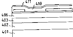
Fig. 4 is the cut-open view of record-header substrate;
Fig. 5 A to 5E is a cut-open view, is used to illustrate the making step according to substrate of the present invention;
Fig. 6 is the partial plan according to substrate of the present invention;
Fig. 7 has shown that the part according to record-header of the present invention cuts stereographic map;
Fig. 8 is the stereographic map that is used to illustrate according to record-header bearing of the present invention;
Fig. 9 is the stereographic map that has shown according to recording unit of the present invention.
Describe embodiments of the invention in detail below in conjunction with accompanying drawing.
Fig. 1 has shown and has been used for the substrate 100 of ink jet print head according to an embodiment of the invention.As shown in Figure 1, in the substrate of record-header, in film forms technology, form and corresponding first resistive element 102 (hereinafter referred to as heating resistance element) of a plurality of inkjet mouths, its each be used to produce the boiling phenomenon that causes in the China ink and from the heat energy of an inkjet mouth ink-jet.Be formed with thereon in the single substrate of heating resistance element, in film forms technology, form such as the driver 104 that is electrically connected with a plurality of heating resistance elements 102, be used for and the line output serial be input to the pictorial data of record-header shift register 106, be used for temporarily storing the latch cicuit or the like of the data of shift register 106 outputs.In addition, in substrate 100, in being used to form the identical process of heating resistance element 102, also be formed with as the temperature controlling resistance element 110 of second resistive element with as the measuring resistance element 112 of the 3rd resistive element.
Each second resistive element, be used for substrate 100 is heated to keep constant Mo Wendu (glutinousness) thus even when the environment temperature of record-header changes, also can guarantee the resistive element of stable ink-jet as described above.The 3rd resistive element 112 (hereinafter referred to as the measuring resistance element) has shape W
3* l
3(width * length) is with the shape W with respect to heating resistance element
1* L
1Satisfy and concern L
1/ W
1<l
3/ W
3Thereby, have resistance value greater than the resistance value of heating resistance element (first resistive element) 102; The resistance value of heating resistance element 102 is estimated.The resistance value of measuring resistance element 112 is measured with method as described below, and calculates the face resistance value of this measuring resistance element.The resistance value of heating resistance element 102 can estimate from the face resistance value that calculates.In addition, when measuring resistance element 112 has bigger resistance value, can be with the resistance value of higher precision measure measuring resistance element, and its result, be the resistance that can estimate heating resistance element with higher precision.
When the replaceable head with this class resistance element was contained on the bearing of printer, the resistance of the measurement of record-header 410 (the 3rd) resistive element was read.In this reading method, a steady current is added on the measuring resistance element, and the value of this measuring resistance element is to change from the magnitude of voltage of measuring constantly at this.For example, the steady current of 10mA is added on this measuring resistance element, and measures the magnitude of voltage of 1.2V constantly at this, thereby the resistance of determining the measuring resistance element is 120 Ω.
Because first, second and the 3rd resistive element are to form in the technology at single film to form, heating resistor layer has identical substantially thickness in substrate.At this moment, when being formed, these elements have W
1=20 μ m, L
1=120 μ m, W
3=100 μ m, and l
3=1,300 μ m, and the face resistance of resistive layer is when getting 22.8 Ω/unit area, and the resistance of heating resistance element is given by the following formula:
R
1=L
1/W
1×22.8=136.8Ω
And the resistance of measuring (the 3rd) resistive element is given by the following formula:
R
3=l
3/W
3×22.8=296.4Ω
When resistance value is when reading with above-mentioned resistance measurement method, the magnitude of voltage of first resistive element is 1.37V, and the magnitude of voltage of the 3rd resistive element is 2.96V, thereby reading accuracy has been improved about 2.2 times.
As mentioned above, when the resistance value of measuring resistance element is set greater than the resistance value of heating resistance element, can measures the resistance value of heating resistance element satisfactorily, and can set the signal that will offer heating resistance element satisfactorily.In this embodiment, the resistance value of measuring resistance element is set to about 2.2 times of resistance value of heating resistance element, but it only need be at least 1.5 times of the resistance value of heating resistance element.Yet it preferably is set to the twice at least of heating resistance element, to obtain sufficiently high precision.
Fig. 2 is a block diagram, has shown the setting that is used for providing to substrate shown in Figure 1 100 drive signal.In Fig. 2, a logical circuit 205 will provide the steady current of the power supply 201 that drives required electric energy (signal) to offer measuring resistance element 112 from being used to, by the output voltage of an amplifier 203 amplifications from resistive element, carry out A/D conversion by 204 pairs of amplifying signals of an A/D converter, and the driving pulse according to the resistance value signal sets of measuring resistance element is provided to heating resistance element 102.
Fig. 3 is a block diagram, has shown the status of electrically connecting that obtains when this record-header is installed on the ink jet recording device main body.
As shown in Figure 3, this record-header is connected with an electric mounting circuit boards 200 of equipment body through a flexible cable 304.At this moment, flexible cable 304 and electric mounting circuit boards 200 are connected with each other through a connector 305, record-header is connected by a pressure contact 303 with flexible cable, and substrate 100 and printed circuit cable circuit board 302 are connected with each other by lead bonding part 301.
Fig. 4 is the cut-open view of substrate, and wherein heating resistance element forms in the manufacture craft at film and is formed on the common base.
The making step of this substrate is described below in conjunction with Figure 4 and 5 A to 5E.
As shown in Figure 4, in the SOI substrate, formed function element (shift register, power transistor or the like) by p and n type doped region.Single crystalline layer beyond this function element forms the district obtains thermal oxide by the LOCOS method, to form an accumulation layer and one simultaneously at the element insulating layer of well heater below 402.Utilize the CVD method to form a psg film layer 403, utilize photoetching technique on this psg film layer, to form a through hole, and form one the one Al electrode film 407 with sputtering method thereon.Utilize photoetching technique on this Al electrode film, to form pattern.Utilize the plasma CVD method on the psg film layer, to form one the 1.4 thick SiO of μ m
2(silicon dioxide) film as insulating intermediate layer 406, utilizes photoetching technique to form a through hole in this insulating intermediate layer, and forms TaN film as resistive layer 408 thereon with sputtering method.Subsequently, on this TaN layer, form a second electrode lay 409 (Fig. 5 A) with sputtering method.In order to utilize photoetching technique to form first resistive element 501, second resistive element 502 and the 3rd resistive element 503 of heat effect part with pattern shown in Figure 6, simultaneously dry corrosion carve the second electrode A l layer 409, as the tantalum nitride layer (TaN 408) and hafnium boride (HfB) layer (Fig. 5 B) of resistive layer, and wet corrosion carves the second electrode A l layer 409 (Fig. 5 C), thereby forms heating resistance element 501,502,503.
With the SiN layer of plasma CVD method formation as protective film, and thereon with the Tc layer (Fig. 5 D) of sputtering method formation as second protective seam.On this Tc layer, form pattern with photoetching technique, and on this SiN layer, form a through hole, extract part (Fig. 5 E) with an open electrode.
The method of utilizing this measuring resistance element suitable drive signal to be offered head will be described below.
When replaceable head was installed on the bearing of printer main body, the logical circuit 205 of printer main body by measuring voltage, current value or the like, came the resistance value of the measuring resistance element 112 of playback record head.This logical circuit is estimated the resistance value of heating resistance element 102 according to the resistance value of measuring resistance element 112, even and when the resistance value of measuring resistance element 112 is in the range of tolerable variance, also by utilizing the method for the drive signal of determining that ink-jet stable with respect to measuring resistance component resistance value is required, set and obtain the constant desired pulse width of drive signal (electric energy), this drive signal will be added to emission resistive element 102.This logical circuit is according to pictorial data subsequently, with respect to resistance value-this value of measuring resistance element 112 with said method read-the stable required drive signal of ink-jet is added on the well heater 102.
In the description of the foregoing description, outside heating resistance element and temperature controlling resistance element, also be provided with the measuring resistance element, and the resistance value of this measuring resistance element is read by equipment side.Yet, form in the head of the bubble in the China ink at allowable temperature controlling resistance element, or drive signal is being offered temperature controlling resistance element in China ink, not form in the head of bubble, the resistance value of this temperature controlling resistance element can be set greater than the resistance value of heating resistance element, and can be used as the measuring resistance element.
In the case, this equipment must have one and be used for the switch that switches between temperature control component driving circuit and metering circuit, and expense increases slightly.Therefore, as a measuring resistance element is set in the above-described embodiments independently.
Fig. 7 has shown an ink jet print head 710, has wherein formed ink passage wall components 701 in substrate 600 of the present invention, to form ink passage 705 and inkjet mouth 700.In this substrate, formed the heating unit 702 that comprises heating resistance element, the line 703 that links to each other with this heating resistance element and top other elements of the present invention described in conjunction with Figure 1.
From the China ink that the ink supply port of record-header provides, be directed into the common ink chamber 704 that is used for providing China ink, and be provided to ink passage from this common ink chamber to a plurality of ink passages.When drive signal was provided to the corresponding heating resistance element of ink passage by line 703, this heating resistance element produced the heat that will be added on the China ink.By this heat, China ink has formed bubble and the pressure when forming bubble, and ink droplet comes out from each inkjet mouth 700 is injected.
Fig. 8 has shown according to record-header bearing of the present invention.
China ink jars 801 is connected with a head unit 810 by ink guide part 802, integrally be provided with four corresponding to the record-header such as four kinds of yellow, pinkish red, blue or green and black colors on head unit 810, each record-header all has above-mentioned setting as shown in Figure 7.
When the record-header that has above-mentioned setting or bearing can be contained on the recording unit main body with pulling down, and signal is offered at 710 o'clock of this record-header from this equipment body, can obtain to realize the ink jet recording device of high-speed record and high picture quality record.
The ink jet recording device that adopts record-header of the present invention is described below in conjunction with Fig. 9.Fig. 9 is a schematic isometric, has shown an example having used ink jet recording device 900 of the present invention.
Record-header bearing 910 is installed on the bearing 920, and bearing 920 is meshed with the helicla flute 921 of a screw mandrel 904, and screw mandrel 904 by driving force transmit gear 902 and 903 and with a CD-ROM drive motor 901 just/reverse turn synchronously rotates.Record-header bearing 910 is along the direction shown in arrow a and the b, moves along a guides 919 with bearing 920 and the driving force that produces by CD-ROM drive motor 901.Be used for being advanced to the pressboard 905 of the recording chart P on the platen 906, cross the support movement direction and recording chart P is pressed on the platen 906 by a recording medium feeder (not shown).
Photo-coupler 907 and 908 plays a part to be used for to confirm the initial position pick-up unit that a lever 909 of bearing 920 exists at respective regions, and carries out the switching or the like of the rotation direction of CD-ROM drive motor 901.Support component 920 is supporting the cover 911 on the whole surface that is used to cover above-mentioned record-header 910.The inside of aspirator 912 suction cover parts 911, and aspirate recovery operation by lid inner opening 913 pairs of record-headers 910.A removing scraping blade 914 obtains the support of a movable part 915, so that can move along the direction of front and back, and these parts are subjected to the support of body supports plate 916.Noting removing scraping blade 914 does not need to have shape shown in Figure 9, but a kind of known removing scraping blade can be used to this embodiment.A lever 917 is used to begin to aspirate the suction operation of recovery operation, and is moved when the cam 918 with bearing 920 engagements moves.According to driving force,, the mobile of lever 917 controlled by known conveyer such as clutch switch from CD-ROM drive motor 901.The main body side that equipment is set is provided with a print control unit (not shown), a signal to be provided and to carry out above-mentioned mechanism and carry out drive controlling to being arranged on heating resistance element on the record-header 910.
The ink jet recording device 900 that has above-mentioned setting, when crossing the whole width that is fed to the recording chart P on the platen 906 by the recording medium feeder and moving back and forth, carry out record, and record-header 910 made by said method, thereby can carry out high precision, high-speed record
In the foregoing description, substrate is applied in the ink jet print head.Yet this substrate according to the present invention can be applied on for example hot head.
In ink-jet recording system, the present invention provides excellent effect especially in a kind of record-header and a kind of recording unit, this record-header and recording unit adopted propose by CANONINC , be used to utilize heat energy to carry out the system of ink-jet.
As the representativeness setting and the principle of this ink-jet recording system, preferably adopt by utilizing such as United States Patent (USP) the 4th, 723,129 and 4,740, the ultimate principle of announcing in No. 796 and the ink-jet recording system realized.Said system can be applicable to so-called type and the continuous type of needing.Particularly, needing under the situation of type, this system is effective, because by at least one drive signal-this drive signal corresponding to recorded information and provided the dramatic temperature that surpasses nuclear boiling and rise-be added to paper or maintain on each electric heating energy conversion component that the fluid passage of liquid (China ink) is provided with accordingly, just can produce heat energy by this electric heating energy conversion component, on the heat effect surface of record-header, realizing film boiling, thus can be in liquid (China ink) with drive signal one to one mode form bubble.By through inkjet mouth by the growth of bubble with shunk atomizing of liquids (China ink), formed at least one ink droplet.If this drive signal is used as pulse signal and applies, the growth of bubble and contraction just can realize immediately, and be enough to realize by this extra high response characteristic the injection of liquid (China ink).As pulse drive signal, at United States Patent (USP) the 4th, 463,359 and 4,345, the signal of announcing in No. 262 is suitable for.It should be noted, by adopting at United States Patent (USP) the 4th, 313, No. 124-it relates to the condition of the temperature rate-of-rise-middle announcement on heat effect surface, can realize more excellent record.
Setting as record-header, except resemble as described in the above-mentioned instructions as with setting that inkjet mouth, fluid passage and electric heating energy conversion component (linear fluid passage or right angle fluid passage) combine, the present invention also comprises employing United States Patent (USP) the 4th, 558,333 and 4,459, No. 600 setting, these patents have announced to have the layout that is arranged on a heat effect part in the bending area.In addition, the present invention also can be applied to the device according to Japanese Patent Application Publication 59-123670 number effectively, and the disclosure has been announced and utilized the device of a public slit as the ink-jet part of electric heating energy conversion component; The present invention also can be applied to according to the device in Japanese Patent Application Publication 59-138461 number, and the disclosure has been announced the device of the opening with corresponding with the ink-jet part, as to be used to absorb heat energy pressure wave.
In addition, as have with can be by all fronts type record-header of the corresponding length of width of the dominant record medium of this recording unit record, can adopt to combine and satisfy the device of length completely, or form the device of the single record-header that record-header obtains by integral body by a plurality of record-headers that will announce in the above-mentioned instructions.By this record-header, the present invention can more effectively present above-mentioned effect.
In addition, the present invention for adopt commutative chip-shaped record-header or with the situation of the whole box type record head that is provided with of record-header itself also be effective, this record-header can be electrically connected or receive the China ink from equipment body on being installed into equipment body the time with equipment body.
Preferably add the device that recovery device, elementary servicing unit or the like are provided with as the layout of recording unit of the present invention to record-header, further stable because therefore effect of the present invention can obtain.For record-header, the example of these devices comprises the preheating apparatus that covers lid arrangement, scavenge unit, pressurization or aspirator and adopt electric heating energy conversion component, another kind of heating element or its combination.Carrying out a pilot injection mode of spraying independently with record, also is favourable for stable record.
In addition, recording mode as recording unit, the present invention is not only extremely effective for having the recording mode that only adopts such as the black basic colors that waits, and adopt multiple different colours or the panchromatic mode that realizes by blend of colors also is extremely effective for having at least one, though these modes can be by adopting whole record-header or realizing by a plurality of record-headers are combined.
In addition, in an embodiment of the present invention, China ink is described to liquid.In addition, the present invention can adopt in room temperature or more solidify and the China ink of or liquefaction softening in room temperature or the China ink that has been liquefied when having applied tracer signal under the low temperature, because in above-mentioned ink-jet system, the general practice is that the temperature of Miboin body is controlled in the scope between 30 ℃ and 70 ℃, so that the viscosity of China ink is in the scope of stablizing ink-jet.In addition, can rise as being used for China ink, prevent that the temperature that heat energy causes from rising, thereby perhaps adopt the China ink that under user mode not, solidifies to prevent the evaporation of China ink by utilizing this temperature from the solid-state energy that changes to liquid state.Under any circumstance, the present invention can be applied to such situation, wherein can adopt the China ink that can obtain liquefying by heat energy-such as making the China ink that liquefied and obtain spraying when the heat energy that has applied according to tracer signal under liquid state, begin China ink that solidifies or the like when reaching recording medium.In the case, China ink can be liquid or solid-state being maintained at down in the groove part or through hole that a porous plate makes, as in Japanese Patent Application Publication 54-56847 or 60-71260 number announce, and this porous plate can relatively be provided with the electric heating energy conversion component.In the present invention, for above-mentioned China ink, the system that carries out above-mentioned film boiling method is the most effective.
According to head device of the present invention and driving method thereof, can be used under the situation of cloth, yarn or the like enterprising line item, and be specially adapted to have the print system that is used for cloth, yarn etc. is carried out the equipment of pre-or aftertreatment.
As mentioned above, substrate of the present invention has on electricity and heating resistance element and function element measuring resistance element independently, and the latter has the resistance value greater than the resistance value of heating resistance element.Therefore, can under the situation of the influence that is not subjected to function element, measure this resistance value, and can realize with higher precision the measurement of this resistance value.
By this structure,, can prolong the serviceable life of heating resistance element itself significantly owing to suitable driving voltage can be added on the heating resistance element.
Owing to adopted above-mentioned substrate according to record-header of the present invention and ink gun bearing, they can receive the electric signal of setting according to the resistance value of accurately measuring.Therefore, the bubble in the head unit forms and can be stablized, and can prevent the variation and the ink-jet error of ink-jet.Even when the resistance value of heating resistance element because the difference of making and slightly not simultaneously, this head also can receive and resistance value corresponding driving signal.Therefore, can provide the record-header that can improve output.In addition, owing to need on the circuit board of record-header, not form memory circuit, can provide low-cost and compact record-header.
In recording unit of the present invention, even when replacement head, have the heating resistance element that has different resistance values right overhead, this resistance value also can accurately be read from the measuring resistance element of each record-header of installing, and can suitable drive signal be added on the heating resistance element of respective record head according to this measured resistance value.Therefore, even when changing record-header, maybe when a plurality of record-header has been installed, also can realize gratifying record.In record-header driving method according to the present invention, according to the data of measured resistance value not needs be stored on the printed circuit board (PCB), and the resistance value of the measuring resistance element in the head is directly read by the electricity means.Therefore, can realize compact head, and can set the drive signal that the resistance change with heating resistance element accurately meets more easily than traditional drive signal establishing method.
Claims (7)
1. one is used for the ink jet print head that writes down by ink-jet, comprising:
The inkjet mouth that is used for ink-jet;
Be used for China ink is directed near the ink passage of the position described inkjet mouth;
A substrate, it has and is used for by heat being applied to China ink upward carries out ink-jet from described inkjet mouth a plurality of heating resistance elements, each resistive element has a resistance, be used for drive signal is provided to a plurality of line electrodes of described heating resistance element, one is electrically connected with described heating resistance element and connects the function element that is used for driving selectively described a plurality of heating resistance elements, with a measuring resistance element, this measuring resistance element on electricity with described heating resistance element and described function element independence and have resistance value mutually greater than the resistance value of each described heating resistance element, described measuring resistance element is arranged such that its resistance value can be measured.
2. according to the head of claim 1, further comprise:
A temperature controlling resistance element, it is independent mutually with described heating resistance element and described measuring resistance element on electricity, and is used to heat is applied in the described substrate.
3. according to the head of claim 1 or 2, wherein said heating resistance element and described measuring resistance element are to be made of the resistive layer of making in single technology.
4. according to the head of claim 3, wherein said resistive element is made of tantalum nitride or boronation hafnium layer.
5. according to the head of claim 3, wherein said measuring resistance element also is used as temperature controlling resistance element, it and described heating resistance element independence and be used to heat is applied in the described substrate mutually.
6. one kind is used for the ink jet recording device that writes down by ink-jet, and wherein said equipment is equipped with an ink jet print head in removable mode, and this ink jet print head comprises:
A substrate, it has and is used for by heat being applied to black going up from a plurality of heating resistance elements of inkjet mouth ink-jet, each resistive element has a resistance, be used for drive signal is provided to a plurality of line electrodes of described heating resistance element, a function element that is electrically connected with described heating resistance element and is used for driving selectively described a plurality of heating resistance elements, with a measuring resistance element, this measuring resistance element on electricity with described heating resistance element and described function element independence and have resistance value mutually greater than the resistance value of each described heating resistance element, described measuring resistance element is arranged such that its resistance value can be measured;
The a plurality of inkjet mouths that are used for ink-jet;
Be used for China ink is directed near a plurality of ink passages of the position described inkjet mouth, and described equipment comprises a control circuit, this control circuit is used for coming a value is carried out electrical measurement according to the resistance value of the described measuring resistance element of the record-header of installing, and according to the state of setting the drive signal that is used to drive described heating resistance element based on the value of resistance value electric measurement.
7. record-header driving method comprises:
The a plurality of inkjet mouths that are used for ink-jet;
Be used for China ink is directed near a plurality of ink passages of the position described inkjet mouth;
A substrate, it has and is used for by heat being applied to China ink upward carries out ink-jet from described inkjet mouth a plurality of heating resistance elements, each resistive element has a resistance, be used for drive signal is provided to a plurality of line electrodes of described heating resistance element, one is electrically connected with described heating resistance element and connects the function element that is used for driving selectively described a plurality of heating resistance elements, with a measuring resistance element, this measuring resistance element on electricity with described heating resistance element and described function element independence and have resistance value mutually greater than the resistance value of each described heating resistance element
Wherein the measuring resistance element uses described method to comprise according to the mode of measuring its resistance value:
To carrying out electrometric step with the corresponding value of the electric numerical value that is arranged on a measuring resistance element on the record-header, this record-header is used for carrying out record according to the heat that is produced by heating resistance element, and the resistance value of described measuring resistance is greater than the resistance value of described heating resistance element;
Set the step that will be added to the drive signal on the described resistive element according to this electrical measurement; And
The drive signal of setting is added to the step on the described heating resistance element of described record-header.
Applications Claiming Priority (3)
| Application Number | Priority Date | Filing Date | Title |
|---|---|---|---|
| JP05223495A JP3143549B2 (en) | 1993-09-08 | 1993-09-08 | Substrate for thermal recording head, inkjet recording head using the substrate, inkjet cartridge, inkjet recording apparatus, and method of driving recording head |
| JP223495/93 | 1993-09-08 | ||
| JP223495/1993 | 1993-09-08 |
Publications (2)
| Publication Number | Publication Date |
|---|---|
| CN1104151A CN1104151A (en) | 1995-06-28 |
| CN1061000C true CN1061000C (en) | 2001-01-24 |
Family
ID=16799041
Family Applications (1)
| Application Number | Title | Priority Date | Filing Date |
|---|---|---|---|
| CN94115141A Expired - Lifetime CN1061000C (en) | 1993-09-08 | 1994-09-08 | Substrate for thermal recording head, ink jet recording head using the substrate, recording apparatus with the recording head, and method of...... |
Country Status (11)
| Country | Link |
|---|---|
| US (3) | US5943070A (en) |
| EP (1) | EP0641656B1 (en) |
| JP (1) | JP3143549B2 (en) |
| KR (1) | KR0138202B1 (en) |
| CN (1) | CN1061000C (en) |
| AT (1) | ATE199231T1 (en) |
| AU (1) | AU677086B2 (en) |
| CA (1) | CA2131423C (en) |
| DE (1) | DE69426717T2 (en) |
| ES (1) | ES2154668T3 (en) |
| TW (1) | TW278296B (en) |
Families Citing this family (35)
| Publication number | Priority date | Publication date | Assignee | Title |
|---|---|---|---|---|
| JP3323597B2 (en) | 1993-09-03 | 2002-09-09 | キヤノン株式会社 | Substrate for inkjet head, inkjet head using the substrate, and inkjet printing apparatus |
| JP3143549B2 (en) * | 1993-09-08 | 2001-03-07 | キヤノン株式会社 | Substrate for thermal recording head, inkjet recording head using the substrate, inkjet cartridge, inkjet recording apparatus, and method of driving recording head |
| IT1276469B1 (en) * | 1995-07-04 | 1997-10-31 | Olivetti Canon Ind Spa | METHOD FOR STABILIZING THE THERMAL WORKING CONDITIONS OF AN INKJET PRINTING HEAD AND RELATED PRINTING HEAD |
| JPH1024584A (en) | 1996-07-12 | 1998-01-27 | Canon Inc | Liquid discharge head cartridge and liquid discharge device |
| DE69725073T2 (en) | 1996-07-31 | 2004-07-08 | Canon K.K. | Recording head and recording method |
| US6102515A (en) * | 1997-03-27 | 2000-08-15 | Lexmark International, Inc. | Printhead driver for jetting heaters and substrate heater in an ink jet printer and method of controlling such heaters |
| JPH11115173A (en) * | 1997-07-11 | 1999-04-27 | Lexmark Internatl Inc | Ink-jet printer with printhead having integral substrate heater driver |
| US6312080B1 (en) | 1997-10-30 | 2001-11-06 | Xaarjet Ab | Ink jet printer |
| JP2001071499A (en) * | 1998-09-30 | 2001-03-21 | Canon Inc | Ink-jet recording head, ink-jet device comprising the same and ink-jet recording method |
| US6357862B1 (en) | 1998-10-08 | 2002-03-19 | Canon Kabushiki Kaisha | Substrate for ink jet recording head, ink jet recording head and method of manufacture therefor |
| JP3610279B2 (en) | 2000-04-03 | 2005-01-12 | キヤノン株式会社 | Recording head and recording apparatus provided with the recording head |
| JP2002079673A (en) * | 2000-06-30 | 2002-03-19 | Canon Inc | Ink jet recording head, method of manufacturing ink jet recording head, ink jet recording apparatus, and method of driving ink jet recording head |
| US6869157B2 (en) * | 2001-03-26 | 2005-03-22 | Canon Kabushiki Kaisha | Method of driving and controlling ink jet print head, ink jet print head, and ink jet printer |
| JP2002370363A (en) | 2001-06-15 | 2002-12-24 | Canon Inc | Substrate for ink jet recording head, ink jet recording head, and ink jet recorder |
| JP4183226B2 (en) * | 2001-11-15 | 2008-11-19 | キヤノン株式会社 | RECORDING HEAD SUBSTRATE, RECORDING HEAD, RECORDING DEVICE, AND RECORDING HEAD SUBSTRATE INSPECTION METHOD |
| JP2004050637A (en) * | 2002-07-19 | 2004-02-19 | Canon Inc | Substrate for inkjet head, inkjet head, and inkjet recorder employing inkjet head |
| JP4125069B2 (en) * | 2002-08-13 | 2008-07-23 | キヤノン株式会社 | Inkjet recording head substrate, inkjet recording head, and inkjet recording apparatus using the inkjet recording head |
| US6794753B2 (en) * | 2002-12-27 | 2004-09-21 | Lexmark International, Inc. | Diffusion barrier and method therefor |
| US6890067B2 (en) | 2003-07-03 | 2005-05-10 | Hewlett-Packard Development Company, L.P. | Fluid ejection assembly |
| US20050206679A1 (en) * | 2003-07-03 | 2005-09-22 | Rio Rivas | Fluid ejection assembly |
| JP4497869B2 (en) * | 2003-09-04 | 2010-07-07 | キヤノン株式会社 | Circuit board manufacturing method |
| TWI267446B (en) * | 2003-11-06 | 2006-12-01 | Canon Kk | Printhead substrate, printhead using the substrate, head cartridge including the printhead, method of driving the printhead, and printing apparatus using the printhead |
| US7344218B2 (en) * | 2003-11-06 | 2008-03-18 | Canon Kabushiki Kaisha | Printhead driving method, printhead substrate, printhead, head cartridge and printing apparatus |
| KR100694053B1 (en) * | 2004-07-30 | 2007-03-12 | 삼성전자주식회사 | Print head driver of inkjet printer and semiconductor circuit board therefor |
| JP4886187B2 (en) * | 2004-12-15 | 2012-02-29 | キヤノン株式会社 | Inkjet recording head substrate and inkjet recording head using the substrate |
| JP4845415B2 (en) * | 2005-04-18 | 2011-12-28 | キヤノン株式会社 | Inkjet recording head |
| US7540593B2 (en) * | 2005-04-26 | 2009-06-02 | Hewlett-Packard Development Company, L.P. | Fluid ejection assembly |
| US7380914B2 (en) * | 2005-04-26 | 2008-06-03 | Hewlett-Packard Development Company, L.P. | Fluid ejection assembly |
| JP2006321123A (en) * | 2005-05-19 | 2006-11-30 | Seiko Instruments Inc | Heating resistor element, thermal head and ink jet |
| JP4804251B2 (en) * | 2006-07-20 | 2011-11-02 | キヤノン株式会社 | Imaging device and imaging unit |
| KR101313946B1 (en) | 2008-08-29 | 2013-10-01 | 캐논 가부시끼가이샤 | Liquid-discharge-head substrate, method of manufacturing the same, and liquid discharge head |
| JP5393596B2 (en) * | 2010-05-31 | 2014-01-22 | キヤノン株式会社 | Inkjet recording device |
| WO2013016003A1 (en) * | 2011-07-26 | 2013-01-31 | Eastman Kodak Company | Inkjet printhead with test resistors |
| US8439477B2 (en) | 2011-07-26 | 2013-05-14 | Eastman Kodak Company | Method of characterizing array of resistive heaters |
| JP6948167B2 (en) * | 2017-06-15 | 2021-10-13 | キヤノン株式会社 | Semiconductor device, liquid discharge head and liquid discharge device |
Citations (4)
| Publication number | Priority date | Publication date | Assignee | Title |
|---|---|---|---|---|
| JPS6277949A (en) * | 1985-10-02 | 1987-04-10 | Canon Inc | Ink jet recording apparatus |
| JPS63312861A (en) * | 1987-06-16 | 1988-12-21 | Mitsubishi Electric Corp | Thermal printer |
| US4910528A (en) * | 1989-01-10 | 1990-03-20 | Hewlett-Packard Company | Ink jet printer thermal control system |
| EP0511602A1 (en) * | 1991-05-01 | 1992-11-04 | Hewlett-Packard Company | Method and apparatus for controlling the temperature of thermal ink jet and thermal printheads through the use of nonprinting pulses |
Family Cites Families (25)
| Publication number | Priority date | Publication date | Assignee | Title |
|---|---|---|---|---|
| CA1127227A (en) * | 1977-10-03 | 1982-07-06 | Ichiro Endo | Liquid jet recording process and apparatus therefor |
| JPS5936879B2 (en) * | 1977-10-14 | 1984-09-06 | キヤノン株式会社 | Thermal transfer recording medium |
| US4330787A (en) * | 1978-10-31 | 1982-05-18 | Canon Kabushiki Kaisha | Liquid jet recording device |
| US4345262A (en) * | 1979-02-19 | 1982-08-17 | Canon Kabushiki Kaisha | Ink jet recording method |
| US4463359A (en) * | 1979-04-02 | 1984-07-31 | Canon Kabushiki Kaisha | Droplet generating method and apparatus thereof |
| US4313124A (en) * | 1979-05-18 | 1982-01-26 | Canon Kabushiki Kaisha | Liquid jet recording process and liquid jet recording head |
| US4429321A (en) * | 1980-10-23 | 1984-01-31 | Canon Kabushiki Kaisha | Liquid jet recording device |
| US4558333A (en) * | 1981-07-09 | 1985-12-10 | Canon Kabushiki Kaisha | Liquid jet recording head |
| JPS5889386A (en) * | 1981-11-24 | 1983-05-27 | Canon Inc | Thermal head |
| JPS59123670A (en) * | 1982-12-28 | 1984-07-17 | Canon Inc | Ink jet head |
| JPS59138461A (en) * | 1983-01-28 | 1984-08-08 | Canon Inc | Liquid jet recording apparatus |
| JPS6071260A (en) * | 1983-09-28 | 1985-04-23 | Erumu:Kk | Recorder |
| EP0328525B1 (en) * | 1986-10-01 | 1991-06-12 | Siemens Aktiengesellschaft | System enabling the electrical balancing of transducers arranged in inking heads |
| JP2627283B2 (en) * | 1987-11-06 | 1997-07-02 | セイコー電子工業株式会社 | Thermal head and method of manufacturing the same |
| US5175565A (en) * | 1988-07-26 | 1992-12-29 | Canon Kabushiki Kaisha | Ink jet substrate including plural temperature sensors and heaters |
| US5212503A (en) * | 1988-07-26 | 1993-05-18 | Canon Kabushiki Kaisha | Liquid jet recording head having a substrate with minimized electrode overlap |
| JPH03208654A (en) | 1990-01-12 | 1991-09-11 | Canon Inc | Ink jet recorder |
| DE69131362T2 (en) * | 1990-02-26 | 2000-03-23 | Canon Kk | Ink jet recorder |
| JPH05169661A (en) | 1991-12-19 | 1993-07-09 | Canon Inc | Ink jet recording apparatus |
| CA2085551C (en) | 1991-12-19 | 1997-11-25 | Atsushi Arai | Ink jet recording apparatus and method |
| KR0172194B1 (en) * | 1992-10-15 | 1999-03-30 | 미따라이 하지메 | Ink jet recording apparatus |
| JP2932888B2 (en) * | 1993-03-30 | 1999-08-09 | 三菱電機株式会社 | Wire cut electric discharge machine |
| JP3235753B2 (en) * | 1993-05-27 | 2001-12-04 | キヤノン株式会社 | INK JET PRINTING APPARATUS AND CORRECTION METHOD FOR CORRECTING SIGNAL ACCORDING TO OUTPUT FROM TEMPERATURE SENSOR IN THE APPARATUS |
| JP3143549B2 (en) * | 1993-09-08 | 2001-03-07 | キヤノン株式会社 | Substrate for thermal recording head, inkjet recording head using the substrate, inkjet cartridge, inkjet recording apparatus, and method of driving recording head |
| JP3208654B2 (en) | 1996-05-31 | 2001-09-17 | 株式会社フクハラ | Control method and control device for air compressor and drain discharge |
-
1993
- 1993-09-08 JP JP05223495A patent/JP3143549B2/en not_active Expired - Lifetime
-
1994
- 1994-08-26 TW TW083107860A patent/TW278296B/zh not_active IP Right Cessation
- 1994-09-02 CA CA002131423A patent/CA2131423C/en not_active Expired - Lifetime
- 1994-09-02 US US08/300,122 patent/US5943070A/en not_active Expired - Lifetime
- 1994-09-07 DE DE69426717T patent/DE69426717T2/en not_active Expired - Lifetime
- 1994-09-07 AU AU72904/94A patent/AU677086B2/en not_active Expired
- 1994-09-07 EP EP94306581A patent/EP0641656B1/en not_active Expired - Lifetime
- 1994-09-07 ES ES94306581T patent/ES2154668T3/en not_active Expired - Lifetime
- 1994-09-07 KR KR94022432A patent/KR0138202B1/en not_active IP Right Cessation
- 1994-09-07 AT AT94306581T patent/ATE199231T1/en not_active IP Right Cessation
- 1994-09-08 CN CN94115141A patent/CN1061000C/en not_active Expired - Lifetime
-
1999
- 1999-07-09 US US09/350,296 patent/US6257695B1/en not_active Expired - Lifetime
-
2000
- 2000-09-07 US US09/656,016 patent/US6471339B1/en not_active Expired - Lifetime
Patent Citations (4)
| Publication number | Priority date | Publication date | Assignee | Title |
|---|---|---|---|---|
| JPS6277949A (en) * | 1985-10-02 | 1987-04-10 | Canon Inc | Ink jet recording apparatus |
| JPS63312861A (en) * | 1987-06-16 | 1988-12-21 | Mitsubishi Electric Corp | Thermal printer |
| US4910528A (en) * | 1989-01-10 | 1990-03-20 | Hewlett-Packard Company | Ink jet printer thermal control system |
| EP0511602A1 (en) * | 1991-05-01 | 1992-11-04 | Hewlett-Packard Company | Method and apparatus for controlling the temperature of thermal ink jet and thermal printheads through the use of nonprinting pulses |
Also Published As
| Publication number | Publication date |
|---|---|
| CN1104151A (en) | 1995-06-28 |
| EP0641656A3 (en) | 1996-01-24 |
| US5943070A (en) | 1999-08-24 |
| CA2131423C (en) | 2000-11-14 |
| TW278296B (en) | 1996-06-11 |
| JPH0776077A (en) | 1995-03-20 |
| CA2131423A1 (en) | 1995-03-09 |
| KR950008129A (en) | 1995-04-17 |
| EP0641656A2 (en) | 1995-03-08 |
| KR0138202B1 (en) | 1998-05-15 |
| JP3143549B2 (en) | 2001-03-07 |
| ES2154668T3 (en) | 2001-04-16 |
| DE69426717D1 (en) | 2001-03-29 |
| EP0641656B1 (en) | 2001-02-21 |
| US6257695B1 (en) | 2001-07-10 |
| US6471339B1 (en) | 2002-10-29 |
| DE69426717T2 (en) | 2001-08-02 |
| ATE199231T1 (en) | 2001-03-15 |
| AU677086B2 (en) | 1997-04-10 |
| AU7290494A (en) | 1995-03-23 |
Similar Documents
| Publication | Publication Date | Title |
|---|---|---|
| CN1061000C (en) | Substrate for thermal recording head, ink jet recording head using the substrate, recording apparatus with the recording head, and method of...... | |
| US7832843B2 (en) | Liquid jet head | |
| US7654654B2 (en) | Ink jet printer head | |
| CN102821961B (en) | The drive unit of head, tape deck and recording method is shootd out for driving liquid | |
| JPH03203658A (en) | Temperature control device of ink jet printing head | |
| CN1196587C (en) | Ink jet printer | |
| US6474788B1 (en) | Substrate for use of ink jet head, ink jet head, ink jet cartridge, and ink jet recording apparatus | |
| US6281914B1 (en) | Ink jet-type printer device with printer head on circuit board | |
| JP2006326972A (en) | Substrate for inkjet recording head and inkjet recording head having the same | |
| EP0927635B1 (en) | Print head substrate, print head using the same, and printing apparatus | |
| US5077565A (en) | Ink recording apparatus with slider to control jetted ink amount | |
| US20090147057A1 (en) | Liquid ejection head and printing apparatus | |
| EP0885723B1 (en) | Recording element unit, ink jet recording element unit, ink jet cartdridge and ink jet recording apparatus | |
| CN109318595A (en) | Print head and ink jet type Method of printing | |
| CN103802475A (en) | Semiconductor device, liquid discharge head, liquid discharge head cartridge, and printing apparatus | |
| JP2006264283A (en) | Actuator apparatus, liquid injection head, and liquid injection apparatus | |
| JP2003011361A (en) | Head driver and ink jet recorder | |
| JP4497869B2 (en) | Circuit board manufacturing method | |
| JP2009051061A (en) | Inkjet type recording head unit, its manufacture method, and inkjet type recording device | |
| JP2009262486A (en) | Circuit board and liquid delivering apparatus | |
| JPH07186378A (en) | Liquid jet recording head and recorder | |
| JP2003145742A (en) | Substrate for recording head, recording head and recorder | |
| JP2002219806A (en) | Basic body for ink jet recording head, ink jet recording head using it, recorder mounting recording head, and method for driving recording head | |
| JP2000127399A (en) | Electrothermal conversion element substrate, ink jet recording head equipped with it, and ink jet recorder employing it | |
| JPH07144406A (en) | Ink jet recording head and ink jet recorder |
Legal Events
| Date | Code | Title | Description |
|---|---|---|---|
| C10 | Entry into substantive examination | ||
| SE01 | Entry into force of request for substantive examination | ||
| C06 | Publication | ||
| PB01 | Publication | ||
| C14 | Grant of patent or utility model | ||
| GR01 | Patent grant | ||
| C17 | Cessation of patent right | ||
| CX01 | Expiry of patent term |
Expiration termination date: 20140908 Granted publication date: 20010124 |