Be used for making by UV-irradiation energy polymerization or crosslinked liquid raw material from a kind of The device of contact lenses is shown in Fig. 1. Shown in figure, it consists of the following components, With the mould 1 of the STA representation of closing position, energy 2a (is ultraviolet light in the case The source) also have equipment 2b, this equipment is energy that the energy is provided almost being parallel The form guiding of light 3 is radiated on the mould 1. Energy 2a and equipment 2b obviously also can make up Become an individual unit.
In its total design, some patents of mentioning in shown device and the front foreword are said The apparatus structure of introducing as prior art in the bright book is identical, and like this, following explanation can With the difference that is limited to most important feature and is relevant to together prior art of the present invention. EP-A-O367513, especially US-PS-4113224 have narrated very all sidedly and have relevantly always established The details of meter relevant relates to the subjects under discussion such as size, material and stability, and relevant suitable The mechanograph material and relate to the details of processing technology form, therefore, those data are by clear The integral part of claiming to be this explanation Chu (is incorporated herein, for your guidance).
Mould 1 is made up of two die assemblies or double part of mould 11 and 12, and they respectively have The die face 13 and 14 of an arc, and determined together die cavity 15, this has determined again institute The shape of the contact lens CL of making (Fig. 2). Double part of the mould of figure middle and upper part 11 Face 13 are convexs, it has determined back or the bottom surface of contact lenses, and adjoining edge The zone; Double part of the so-called formpiston of double part of this mould. On the contrary, another mould pair The face 14 of half part (corresponding double part of former that be called) is concave, it determined want Similarly adjoin mutually with fringe region in the front of the contact lenses of making.
With mention in the foreword as in file WO87/04390 or EP-A-O367513 Known to the mould difference, die cavity 15 is not sealed fully and closely, but strictly according to the facts Execute shown in the scheme, all open wide around its ring edge district, this district has determined and will make The edge of contact lenses, and as the situation of mould shown in the US-PS-4113224, It is connected with a narrower ring chamber seam 16 at there. This ring chamber seam 16 is subject to Flat mold wall on flat mold wall 17 on double part of formpiston 11 and double part of former 12 Form between 18. In order to prevent that mould is fully closed, if former 12 for example provide with Joint 20 on the packing ring that dried packing ring bolt 19a and 19b form occur, they and formpiston 11 Work in coordination, keep thus double part of two moulds away from enough and consist of described ring Shape chamber seam 16. This packing ring also can be adjustable or elastic construction, borrows such as Fig. 1 the right Help a kind of screw thread with respect to packing ring bolt 19b to represent with signifying. According to the method, Double part of two moulds (used the arrow side that rotates in crosslinked operating period by adjusting washer (disk) Represent to 19c) move towards one another or apply elastic force with compensate for volume shrinkage. This mould Obviously can open or close by usual way, for example only utilize a kind of here only with The closing unit that arrow 1a represents. Also can utilize the closing unit such as the outside, transfer Save the distance between double part of two moulds, with compensate for volume shrinkage.
Organization plan according to the another kind of this paper is not expressed can provide some sections The die cavity seam replaces continuous annular chamber seam 16 and packing ring 19a and 19b, the section chamber that each is independent Midfeather between the seam has played packing ring. Obviously, other structure also is possible.
Double part of two moulds 11 and 12, its manufactured materials is a ultraviolet light to selected form of energy as mentioned herein, is permeability as far as possible, for example, they can be made up of polypropylene that is usually used in this purposes or other polyolefin.Because ultraviolet light is only from irradiation on one side in the case, only that is to say that from top irradiation therefore the mould 11 (that is to say it is formpiston in the case) above just is can see through ultraviolet light.Obviously, equally also can be from shining below by former.According to suitable and favourable especially organization plan of the present invention, must form by quartz with double part of that mould of UV-irradiation at least.This material not only has good especially ultraviolet light permeability, but also very hard and have anti-patience, thereby can be easy to reuse by the mould that it is made.Below the prerequisite that further disclosed in the details be, the mould closure had not both stressed incomplete yet, thus different contacts of double part of mould and damaging.What may substitute quartz is the special glass or the sapphire that can see through ultraviolet light.Can reuse based on mould or double part of mould, in order to obtain the very high and reusable mould of energy of precision, its manufacturing price is had to higher.Because mould does not contact the lens region of manufacturing, that is to say that in the die cavity district or effectively the die face district does not contact, and has therefore got rid of the damage that causes because of contact.Thereby guarantee the height durability of mould, the machining reproducibility to prepared contact lenses or mechanograph also has good result in general.
When energy is when applying on one side, away from double part of mould of the energy in principle can with any can be with bridging property or the crosslinked material or the material of its component compatibility.But, if usefulness is metal, then with the difference of irradiation energy kind, must reckon with the possibility of reflection, this can cause over-exposed, forms undesirable effects such as defective in the corner.The light absorptive material does not have those shortcomings.
So far, this device, especially mould 1, is equivalent to the sort of device of mentioning among the US-PS4113224 haply.Main notion below the present invention, the most obvious most important again difference of device that discloses with this patent is, being radiated on the material of making mechanograph causes crosslinked form of energy to be limited in die cavity, just, have only the bridging property material of position in die cavity to be shone by suitable form of energy (being ultraviolet light in the case), the material that only is positioned in the die cavity has taken place crosslinked.Especially, being positioned at material in the ring chamber of the die cavity seam and the material that is positioned in the possible storage channel that links to each other with the chamber seam is not crosslinked owing to not being subjected to optical energy irradiation." die cavity " refers to the inner chamber of the mould after the sealing, and it is by the mechanograph that will make, therefore is that the whole shape of contact lenses limits specifically.Therefore, the annular chamber seam 16 that enters die cavity does not constitute the part of die cavity 15.
In order to know main concept of the present invention, embodiment according to Fig. 1 and 2 shown device, stitch on the 16 regional mold walls 17 at ring chamber a kind of mask 21 is set, it is lighttight (or compare with the permeability of mould at least be that light transmission is very poor) to used form of energy (in the case for ultraviolet light), mask accurately extends till die cavity, except that die cavity, all the other all parts, uncrosslinked with liquid state (may be excessive) material contact the die cavity or the die surface that maybe may contact all can isolate with irradiation.According to method of the present invention, the subregion of rims of the lens is not the restriction because of the mold wall material, but because of causing that polymerization or crosslinked irradiation or the spatial constraints of other form energy form.Further provide the details of this device below with reference to Fig. 2-5.
Under the ultraviolet light situation, this mask can preferably a kind of thin chromium mask layer, and this mask can be by known method as taking a picture and ultraviolet flat stamping method make.Other metal or metal oxide also can be suitable mask materials.This mask can also scribble layer protective layer such as silica, if double part of mould therefor or mould is quartzy.This mask not necessarily will be fixed, but for example can make or device becomes movable or interchangeable.In addition, mask installs as Fig. 2-5 neither be indispensable, and device is favourable although it is so.In principle, mask can install in mould or on the mould Anywhere, as long as it can play the effect of being wanted, can hide and exclude the All Ranges that die cavity is loaded with uncrosslinked material mould outward.In principle, as long as the energy of irradiation can be limited to die cavity by some other method, need be, even can save the mask of mould or hide parting with respect to the occasion of the optical effect of mould.Under the situation of UV-irradiation, can realize this point, for example can adopt the light source of limited space system, a kind of suitable lens devices is optional in conjunction with outside mask, and dividing plates etc. are also taken the former effect of light of mould into account.
Each step of making contact lenses is as follows substantially:
---under mould 1 unlatching situation, add liquid, uncrosslinked raw material for 12 li toward double part of former.Usually measure excessive amount, that is to say, the volume of metering is greater than the volume of die cavity 15 with the contact lens CL that will make.
---closing molding 1, when shutting double part of two moulds, excessive material is pressed into the ring chamber seam 16 between double part of two moulds 11 and 12.This chamber seam 16 is made so wide or high (△ Y), makes and can avoid contact between double part of two moulds in mask 21 districts 11 and 12 definitely reliably.The guiding of two double parts and location (at interval) are that the director element and the stopping element of outside carry out by being positioned at more, and also the device from US-PS4113224 is known on principle in this location, only represents with packing ring bolt 19a and 19b at this.In order to make contact lenses, typical chamber seam height △ Y is in the scope that is lower than about 100 μ m.Test shows, when adopting parallel optical energy irradiation, at least still may make the mechanograph edge of well-balanced structure, even the height of used chamber seam is about 1mm.On the contrary, the width of chamber seam or height and can also be reduced to almost nilly easily, the closure as long as mould does not stress that is to say, the position of double part of two moulds be one on the top of another part and the pressure that does not add.In the case, have only the uncrosslinked material membrane of several micron thickness to stay seam district, chamber between double part of two moulds, this district still can not cause forming burr owing to shielded UV-irradiation.Based on the closure effect of not stressing of mould, as long as choose suitable material at least, mould does not damage yet.
---the polymerization of material in die cavity 15 and crosslinked.By UV-irradiation (perhaps, using the energy exposure of suitable form usually), in the contact lenses zone that is equivalent to make (or be equivalent to usually will make mechanograph zone), raw material carry out polymerization or crosslinked.
---open mould and take out crosslinked contact lenses.Raw material in die cavity 15 polymerization or crosslinked after, double part of mould 11 and 12 is separated from each other, for example can adopt the device that is not illustrated, open mould 1 thus.Contact lenses become and can arbitrarily pass in and out, and can take out with hand or with also unshowned device.Need, can the known appropriate method of employing itself guarantee that the contact lenses that make like this are preferably still attached on one of double part of mould or another.Suitable method for example has introduction in U.S. Pat-PS4113224.
Fig. 2 shows with the topology layout to transition region in die cavity 15 and circular passage 16 of the mould 1 that amplifies the details form.Die cavity 15 has as an example and is equivalent to the typical edge geometry of so-called contact lens CL among the figure.Therefore die cavity edges also is that the edge of lens here is to be made of two walls 22 and 23, and 22 and 23 each other by accurate angle configurations, and is configured in respectively on formpiston and double part of former 11 and 12.This two mould walls wide and high, and the wide and height of the contact lenses marginal zone that is limited by them is represented with X and Y respectively.Obviously, this rims of the lens in fact also can be slightly circular.
Can clearly be seen that, the cylindrical wall 23 of double part of former 12 also not exclusively extends to till double part of the formpiston 11 flat wall 22 and wall 17, be in seamless state, but be lower than the amount of △ Y, consequently, formed already mentioned annular chamber seam 16 between double part of mould 11 and 12 wall 17 and the wall 18, mould does not still have closure in other words.
In this embodiment, be arranged on the wall 17 of double part of former 11 mask 21 accurately horizontal-extending up to the extension 23a of double part of former, 12 walls 23.If cause crosslinked ultraviolet light collimated light beam 3 to project on wall 22 and 17 with accurate angle, and parallel projection is on cylindrical wall 23, mask is positioned at accurate angle below 21 space is to be under the shade, only be positioned at the material of die cavity 15, that is to say be positioned at imaginary wall extension 23a with material just take place crosslinked, produce clean thus and carrot-free glasses edge, this edge need not remake further machining.Therefore, if adopt parallel optical energy irradiation, do not consider that the shape of diffraction and diffuse transmission influence (in fact this influence can be ignored) mask 21 is sent into the fringe region of contact lenses by parallel the handing down with (in the case) of two dimension.Therefore, if double part of two moulds 11 and 12 each other by the annular chamber seam 16 height △ Y of being separated by, the edge of formation is beyond the zone that is produced by the displacement that utilizes the energy exposure spatial constraints.
Also may utilize diffraction and/or scattering effect in principle, not think like that sharp keen or have the mechanograph of slightly circular corner to make profile by a kind of controllable method.The mask that employing has local different light transmissions also can reach same effect.Therefore the sharp keen moulded parts of edge angle to making can round according to controllable method, and its method is that control is not exclusively crosslinked and be partly dissolved incomplete crosslinked zone with suitable solvent (this solvent also can be a uncrosslinked material itself).For example, isopropyl alcohol is a kind of suitable solvent under HEMA (hydroxyethyl methacrylate) situation.
The mechanograph that makes by the sort of method is after the demoulding, anyly can utilize suitable solvent to be easy to wash off attached to the uncrosslinked material on the mechanograph, and these solvents are different with material, even may be water.
In the embodiment of apparatus of the present invention shown in Figure 3, cause crosslinked energy to work by double part of former 12 (that is to say below) from figure.Therefore, mask 21 is provided on the wall 18 of double part of former 12 rather than on the wall 17 of double part of formpiston 11 in this structure.Otherwise this structure does not just have difference with the structure of Fig. 1 and 2.
In the embodiment of Fig. 4, energy exposure is still on double part of formpiston, 11 one side, and mask 21 is on the wall 17 of double part of this mould.But, double part of former 12 that is to say here not being raised, and saved among Fig. 2 the cylindrical wall with 23 double part of former of representing.And that ring chamber stitches is 16 corresponding wideer or higher.Test shows, adopts the size that is commonly used to make contact lenses, and the structure of this mould also produces the zero defect result.
At last, be equivalent to the scheme of Fig. 4 according to the embodiment of Fig. 5, difference is that in the case, energy is again to work from the below by double part of former 12, and mask 21 is provided on double part wall 18 of this mould.
Obviously, Yi Bian cause crosslinked energy to be incident upon on the bridging property material in the die cavity not only can also can to carry out from carrying out from both sides.Just must be careful, energy can only enter die cavity, and isolates effectively with remainder.This can as by two of suitable configurations or may in addition more the polylith mask realize.One or more mask neither install on the surface of mold wall, can be provided in mold wall inside.Preferably install on or just in time under the wall, because may get rid of undesirable diffraction and scattering effect basically like this with a wall of uncrosslinked material contact.
According to a further form of the present invention, one of double part of two moulds also can be used as the encapsulation of contact lenses subsequently.For this reason, both can adopt double part of formpiston 11, also can be with double part of former 12, entire die is just made like this.Figure 10 and Figure 11 have done this to illustrate, and among each figure, double part of a mould (Figure 10 is double part of formpiston 11, and Figure 11 is double part of former 12) is used as encapsulation subsequently.Double part of these moulds should be able to be made into double part of disposable use mould, and second half of mould can be made into double part of mould (for example being made by quartz or sapphire) that can reuse under each situation.In each case, mask 21 is provided on double part of mould that can reuse.In each case, the energy of ultraviolet light beam 3 double part of mould (exception is not pass through by the zone of masked) by reusing, this double part is easy to see through the irradiation of this energy.In view of by the good lens of die cavity 15 shape moldings after the polymerization attached to double part of disposable mould on, the suitably pre-treatment in addition of this double part.The excess material that is positioned at mask 21 zones is behind polymerization-filling, and polymerization does not take place as yet for it, can remove from double part of mould subsequently.The lens good attached to the polymerization in double part of disposable mould can further place aquation in double part of this mould (aquation if desired) during the processing.The lens that machine are packaged by the method for cutting out and sealing double part of this disposable use mould with a lid paper tinsel subsequently.
Containing of air can take place in another problem according to known method so far produces during manufacture when mould is closed.Air contains causing in the lens that lens are confirmed as waste product in check (quality control) subsequently.Nowadays, mould is correspondingly slowly closed, and air can fully be run out from die cavity as far as possible.But, slow closing molding spent than the relatively large time.
According to another form of the present invention, therefore, requirement can provide this class device of being mentioned of a kind of method and height efficient, that is to say, mould can use effectively, and wherein cost is lower, but always will satisfy this condition, and the mechanograph that promptly makes (as contact lenses) does not contain air.
Solved this problem according to the method, this method is that the raw material that near small part still is in non cross-linked state are packed into die cavity.Consequently, the air that do not have at the very start of being feeded from mould can have been avoided containing of air thus fully in mould.Therefore, mould can be closed quickly, and can more effectively use thus, and meanwhile, cost also contrast is got up very low.In addition, according to this method,, provide institute's expense raw-material accurate measurement naturally because charging occurs in raw material.
In a kind of method of modification, for the purpose of the die cavity charging, die cavity can be connected with the holder around it, has stored raw material in the holder, therefrom is full of die cavity.The method of this modification is simple especially technology.
In the method for another kind of modification, mould also is closed under the raw material state, so that get rid of the danger that air enters die cavity in the closed procedure fully.
Also have in a kind of modification, mould therefor comprises a container and press a movable mould element of piston mode in this container, and for opening and close up for the purpose of the mould, this mould element can keep inverse state to leave chamber wall and go and move towards chamber wall.When opening mould, raw material are fed between chamber wall and the mould element, when mould closes up, again raw material are transported.Because the result that movable mould element is left away with the chamber wall inverse state, the space between movable mould element and the chamber wall is loaded into raw material and does not have air can enter this space.Subsequently, because movable mould element is towards the result that chamber wall moves, the raw material that are between mould element and the chamber wall are transported again, and the material that is positioned in the die cavity is still stayed the there naturally.When mould element was shifted to chamber wall, any air also can not enter die cavity, thus can by simple and effectively way make the mechanograph that does not contain air.
For example, can adopt the mould of double part of two moulds, double part of one of them mould is arranged on the chamber wall, and another is arranged on movably on the mould element.According to this organization plan, can adopt the mould of double part of a formpiston and double part of a former, double part of formpiston is arranged on the chamber wall, and double part of former is arranged on the movable mould element.Can advantageously use pump that raw material are fed and transport.According to the favourable process variant of another kind, can driven plunger with feeding with transport raw material.
Crosslinked mechanograph can take out in mould with raw material flushing mould by very simple method.For example, this can carry out as follows, when opening mould, isolates mechanograph by flowing of raw material in mould, when closing up mould, by raw-material flowing mechanograph is flushed out mould.
In a kind of method of modification, first leg is mould is opened and to be closed up.Subsequently, carry out the crosslinked of necessity by the effect of energy, thereby can make the mechanograph demoulding at least.Second leg is to open mould once more, from wherein isolating mechanograph.The mould element of piston-like and then shift to opposed chamber wall, so mould is closed up again, crosslinked good mechanograph is rushed out mould.The difference of the process variant of this " two bout " is that mechanograph makes at first leg, flushes out mould in second leg then.At " flushing bout ", mould is cleaned simultaneously.
Just now the process variant of speaking of may be undertaken by following wherein a kind of method, a kind of method is, one " manufacturing bout " (first leg) is provided earlier, " flushing bout " (second leg for example adopts a kind of flushing liquid) of a separation is provided then, and other method is, the flushing bout that is provided with can be consistent with the manufacturing bout of new mechanograph, that is to say that when new raw material were introduced die cavity, the mechanograph that last turn-based gets was rinsed out mould.Like this, this " two bout " process variant just becomes a kind of " single bout " process variant.
Crosslinked good mechanograph also can utilize a kind of anchor clamps to take out in mould.This can be undertaken by laxative remedy, and the mechanograph that will take out in the mould with anchor clamps is placed on the movable mould element beyond the space between movable mould element and the opposed chamber wall.The moulded parts that is placed on this element can be fixed by negative pressure fast, deviates from from above once more with malleation then.
In another process variant, raw material are introduced after the die cavity, and mould is not exclusively closed, contain uncrosslinked raw-material ring chamber seam and are still opening thereby make, and stitch round die cavity in the chamber, and be connected with die cavity.By this method, the crosslinked on the one hand middle volume contraction that takes place can be compensated by the raw material that pass back into die cavity through the annular chamber seam, and double part of mould can not pressed during making mechanograph each other firmly on the other hand.Particularly in view of double part of mould the danger that is subjected to the mechanical stress non-reversible deformation is arranged, mould so far is just as disposable use as described in the foreword.And according to this process variant, then double part of mould can be reused.
Can expect that also when crosslinked the carrying out of material, mould closes up along with crosslinked volume contraction.
But importantly, in any occasion, used raw material were that viscosity is flowable before crosslinked at least, and like this, raw material just can flow back to die cavity by the ring chamber seam, with compensate for volume shrinkage.
Solved the problem of may air containing in the device of the present invention, its method is, die cavity is between loading period, and its raw material to small part still is in non cross-linked state.Consequently, just between loading period, can not enter mould, just avoid containing of air like that fully from the beginning air.Therefore, mould can close up sooner, more effective thus use, and meanwhile, cost also contrast is got up very low.
In one embodiment, this device comprises one and is used to provide raw-material holder around die cavity.It can be connected with die cavity.When the die cavity when filling with substance, holder is with the die cavity connection and be full of die cavity.This makes can make simple especially other improvement structure on the some kinds of structures, and more definite details will be illustrated.
In another embodiment, this device comprises the equipment that closes up mould, and this equipment is arranged in the raw material, and in the case, mould also always is enclosed in the raw material, thereby does not have air can enter die cavity.
In an advantageous embodiment, mould comprise a container and one in this container with the movable mould element of piston mode, this element can leave the chamber wall that is positioned at the opposite and go and move towards chamber wall, to open and to close up mould.An inlet is set in the container, and raw material flow between chamber wall and the mould element when mould is opened by inlet.An outlet also is set in the container, and raw material flow out again by it when mould closes up.On this embodiment structure is fairly simple, that is to say, is very uncomplicated, therefore is well suited for actual use.
Mould by this structure preferably has double part of two moulds, and double part of a mould is arranged on the chamber wall, and another double part is arranged on the movable mould element.This mould has (especially when making contact lenses) double part of formpiston and double part of a former.Preferably, double part of formpiston is arranged on that double part of former then is arranged on the movable mould element on the chamber wall.By this structure, mechanograph (contact lenses) demoulding especially simply afterwards.
Some pumps preferably are set are used for feeding and/or transporting raw material, when opening mould, pump feeds raw material between chamber wall and the mould element through inlet, and when mould, pump is transported raw material back through outlet.Therefore and do not mean that any special cost these are pump operated reliable.
In another embodiment, the equipment that drives mould element is provided, element can be pressed the displacement of piston mode.Those equipment that can provide can be arranged on uses pump operation, also can be arranged on the device that does not have pump operation, so that can move towards being positioned at opposite chamber wall direction by the mould element of piston mode displacement, the raw material between double part of mould are excluded again.
In another embodiment of this device, provide to be used for producing mobile equipment.This being flowing in makes mechanograph separate with mould when opening mould, when closing up mould mechanograph is flushed out mould.These equipment can be the form or the similar effective equipment of jet pipe.Importantly, produce a kind of flowing or turbulent flow in their raw material of using between double part of mould, thereby by flowing or move mechanograph (contact lenses) in double part of mould of turbulent flow.
In another embodiment of this device, first leg (" manufacturing bout ") at first flows into raw material between chamber wall and the movable mould element through inlet, back spills out through outlet then.Then, the energy is radiated on the mould, and used energy is enough to make the mechanograph can the demoulding, has consequently taken place crosslinked.In second leg, raw material flow between chamber wall and the movable mould element through inlet once more then, and mechanograph is gone out mechanograph with the mould separation and through outlet.
The difference of " two bout " device is that mechanograph is made at first leg, and mechanograph is rushed out mould in second leg (the flushing bout cleans bout) then, and mould also is cleaned simultaneously.
This device can be made by following wherein a kind of mode, and as previously described, a kind of mode is that one " manufacturing bout " (first leg) arranged earlier, and a flushing bout (second leg) is arranged then; Another kind of mode is that flushing is carried out simultaneously with the bout of making new mechanograph, that is to say, when new raw material were introduced die cavity, the mechanograph that the front turn-based gets was rinsed out mould.Like this, this " two bout " device has become " single bout " device.But, in " single bout " device, must supply flushing with raw material, and in " two bout " device, also can adopt special cleaning liquid.
In order to take out mechanograph, can provide a kind of anchor clamps that take out crosslinked mechanograph in the mould.For this reason, at chamber wall rather than provide on the face of shape a cavity or groove should be arranged, this chamber groove roughly extends at movable mould element moving direction.Anchor clamps are arranged in the groove of chamber.Movable mould element comprises a groove on outer wall, this outer wall is not to be positioned at the opposite that provides the shapes of containers wall, and the anchor clamps in the groove are deposited the mechanograph of taking-up.This is an advantageous particularly and simply install scheme on a kind of structure.
In the improvement structure of a possible other device, this movable mould element comprises a passage, and this passage can lead to negative pressure or positive pressure source.When anchor clamps in the mould element groove had been deposited the moulded parts that takes out, passage was connected with negative pressure source.In order to deviate from lens, passage then is connected with positive pressure source.By this device, lens can be made during one bout, and take out at next bout, leave on the mould element, then take out in mould element.The device that this both can be used in making " two bout " also can be used on the device of making " single bout ".
In another embodiment of device, mould provides packing ring, and this packing ring is lived the apart very narrow fixed distance of double part of two moulds when mould is in closed position, thereby just constitutes the ring chamber seam that centers on die cavity and be communicated with it.
By this device, on the one hand since raw material can through the chamber seam pass back into die cavity make crosslinked in the volume contraction of generation be compensated.On the other hand, packing ring has stoped double part of mould to be pressed firmly each other during mechanograph is made.Especially in view of the danger that non-reversible deformation is arranged because of double part of mechanical stress mould, so far as the only disposable use of double part of mould as described in the foreword.Adopt the embodiment of this device, double part of mould then may be accomplished to reuse.In addition, also have a kind of Design of device, mould provides elastic devices or displacement device, and double part of two moulds drawn close along with crosslinked volume contraction moves together.
Particularly mechanograph, especially optical lens are that contact lenses can be with said apparatus by method manufacturing of the present invention specifically.
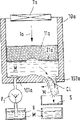
Embodiment according to device of the present invention is shown in Fig. 6 A-C, and this is in order to make contact lenses from a kind of liquid raw material and to design, and these raw material are subjected to can polymerization or crosslinked as UV-irradiation.Fig. 6 A represents that mould 1 is in closed position.Mould 1 is arranged in the container 10, and uncrosslinked liquid raw material M has been adorned in the inside.This device comprises that also the energy 2a of a ultraviolet light form and energy that guiding is provided by 2a are radiated at equipment 2b on the mould 1 with directional light form 3.Equipment 2a also comprises a mask that is arranged between ultraviolet source 2a and the container 10.Obviously, ultraviolet source 2a and equipment 2b can be merged into a single unit.
Mould 1 comprises double part of two moulds 11 and 12, and each double part each has a curve mold face 13 and 14, and both have determined die cavity 15 together, and this has determined the shape of the contact lens CL that will make again.The die face 13 of top double part of mould 11 is fronts spill and that determined to press close to fringe region.Double part of double part of mould, 11 so-called formers.The die face 14 of double part of underlying die 12 is back convex and that determined contact lens CL or the back side and the fringe region pressed close to.Double part of double part of mould, 12 so-called formers.
In the whole manufacturing process, the space between two moulded parts 11 and 12, therefore just die cavity 15 is set in the uncrosslinked raw material M.According to the total notion of the present invention, under any circumstance, die cavity is set in the raw material that are in non cross-linked state between loading period fully at least.Fig. 6 B represents that even double part of top mould 11, neither not have raw material M's fully in the position of opening, the space between double part of mould 11 and 12 always remains on below the liquid level of the raw material M that is deployed in 10 li in container.Therefore, the space between double part of two moulds also is that die cavity always is communicated with the raw material M that is deployed in 10 li in container especially.Its as a result air whenever all can not enter space between double part of two moulds 11 and 12.
When die cavity is filled, when mould is closed up (Fig. 6 A), shine moulds with ultraviolet ray 3, mechanograph takes place crosslinked thus.
After crosslinked, open mould, from mould, deviate from, that is to say and from mould, take away and take away with the mechanograph of contact lens CL form.Fig. 6 symbolically expresses anchor clamps 4 for this purposes, during double part of the mould above mentioning, takes away contact lens CL (Fig. 6 B) and it is taken out (Fig. 6 C) from double part of formpiston 12 in mould.Throw off in the mould and take contact lenses away or mechanograph also can carry out with other equipment of other embodiment as described below.After taking out contact lenses or moulded parts, mould can close up once more, and makes a new contact lens CL.
Owing to occur in below the liquid level of 10 li raw material M of container, do not have air can enter the space between double part of two moulds 11 and 12 or especially enter die cavity 15 by the whole manufacturing process of Fig. 6 A-C.Because mould is opened below liquid level and closed up, mould can also close up quickly, and this is impossible according to the method and apparatus of technical merit.So, can effectively and cheaply produce the contact lenses that do not contain any air.
In the embodiment, in addition, be limited to the material that impinges upon 15 li of die cavitys on the mould shown in Fig. 6 A-C, that is to say it only is that the material that is in 15 li of die cavitys is crosslinked with ultraviolet being incident upon.Especially, be not subjected to optical energy irradiation, be not crosslinked around the raw material of 16 li of the ring chamber of die cavity 15 seams and all the other raw material M of being in 10 li in container.Therefore, here " die cavity " is meant by the determined inner chamber that closes up mould of the whole profile of the moulded parts that will make (being contact lens CL specifically).Therefore, the ring chamber seam 16 that leads to die cavity does not here constitute the part of die cavity 15.
For the purpose of in fact implementing, according to Fig. 6 A-C, stitch at ring chamber on the mold wall 17 in 16 zones a mask 21 is provided, this mask is impervious to used luminous energy (is ultraviolet light at this), or to compare with the permeability of mould at least be to see through very poorly, and mask accurately extends up to die cavity, and does not comprise die cavity, what mask was feasible and liquid state is uncrosslinked may be all remainders that excessive material contacts and maybe may contact, and the die cavity of mould or surface be the exposure energy affect not.The subregion of rims of the lens is not to be made of the restriction of mold wall material, but by initiated polymerization or crosslinked irradiation energy or other can spatial constraints and constitute.The sidewall of top double part of mould also is provided with mask 21, and the raw material around mould take place crosslinked in the container 10 so that stop.
Another embodiment according to device of the present invention is shown in Fig. 7 A-C.In this scheme, double part of a mould (is double part of formpiston in this situation) is to be made of wall of container 10a (is container bottom 100a in this situation).So double part of formpiston just directly constitutes at container bottom 100a.In container 10a, also provide one to press the movable mould element 11a of piston mode, this element can leave and goes and move to container bottom back from the direction of the chamber wall (being container bottom 100a in the case) that is positioned at its opposite, keeps simultaneously sealing along container side wall.Therefore this mould can be opened and closes up by this method.When double part of former just correspondingly constituted mould element 11a on the face 17a in the face of the mould element 11a of container bottom.When mould is in closed position (Fig. 7 A), container bottom 100a and die face 17a have determined die cavity 15a.Certainly, mould element might not be made the form of piston, and it can adhere to double part place of mould equally in the past provides a dividing plate.Other method that changes volume also is possible.
That be provided with at container 10a (is container bottom 100a in this situation) is a root entry pipe 101a, and raw material can flow into space between mould element 11a and the container bottom 100a through it.For this reason, this space constantly is connected with holder R.At the pump P1 and the P2 at inlet 101a and outlet 102a place, raw material can be transported into and transport this space respectively in utilization.Importantly, raw material M always is equipped with in this space, thereby makes air can not infiltrate this space.Pump P1 and P2 represent with the check (non-return) valve of a combination, but also can adopt the pump that do not have the combination check (non-return) valve and with this valve separate connection between pump and container, or depend on the model of pump, can save a kind of like this check (non-return) valve fully.
When mould is in and hold together the position (Fig. 7 A), mould is shone by energy (still is ultraviolet light 3 in this situation).This moment, energy also was to mould from top photograph.Cause crosslinked thus.Crosslinked good moulded parts CL is mentioned from mould and is taken away.For this reason, at first utilize pump P1, the mould element of piston-like move up (Fig. 7 B) with the space of liquid raw material M between inlet tube 101a feeding container bottom 100a and mould element 11a.Then, can isolate the moulded parts of contact lens CL shape in the mould and take away.This can be by carrying out with reference to the special fixtures of Fig. 1 explanation.This contact lens CL can also by as below be rinsed out mould equally being described in more detail.
Can move down again by the mould element 11a of piston mode displacement, the material that is between mould element 11a and the container bottom 100a is transported through outlet 102a (Fig. 7 C).This material can utilize the pump P2 that is arranged on outlet to transport.
In principle, the liquid raw material that can only be fed and transport between mould element 11a and the container bottom 100a by the mould element 11a of piston mode displacement drives, and for this reason, pump P1 and P2 provide the driving energy of its necessity.Also can not have pump fully, can be driven by mechanical system by the mould element 11a of piston mode displacement, that is to say, during mould element moved up, raw material were inhaled into container, and during it moved down, raw material were back extruded again.Obviously, also may be not only with pump but also use Mechanical Driven.
A mask 21a is set on mould element 11a.According among Fig. 6 A-C to double part of upper die, 11 described similar approach, mask spreads over ring chamber seam 16a till die cavity 15a, can also expand to along the sidewall of mould element 11a in case of necessity.If with ultraviolet light 3 irradiation moulds, then only crosslinked in the generation of die cavity 15a zone, the result forms moulded parts subsequently.All the other zones particularly at the material of ring chamber seam 16a, also have other raw material in container 10a not to be crosslinked.In the explanation of Fig. 6 A-C to this mask work about material, the opinion of making and installing equally also can be applied in here basically.
Fig. 8 A-C represents an embodiment of this device, and this scheme is similar to the embodiment of Fig. 7 A-C basically very much.But, a difference is, in the embodiment of Fig. 8 A-C, at outlet 102a place pump P2 is not set, but but this outlet be made into as the piston or the moveable splash board of deformation or do imaging one and fan valve.In the explanation of Fig. 8 A-C, particularly the demoulding of mechanograph (being contact lenses therefore here) will describe in detail below.The charging of die cavity 15a utilizes pump P1 to carry out similarly by the embodiment of Fig. 7 A-C.When mould is in closed position (Fig. 8 A), be radiated at by ultraviolet light 3 to cause the crosslinked contact lens CL that makes on the mould.
When piston-like mould element 11a (Fig. 8 B) was up mobile, liquid raw material flowed into container bottom 100a and can press container 10a between the mould element 11a of piston mode displacement.Inlet 101a can do jet pipe of imaging or the effectively mobile equipment of similar generation.When liquid raw material feeds through entering the mouth, because what produce flows, and the jet pipe that has adopted appropriate designs, crosslinked contact lens CL is mentioned in mould, and be rinsed to outlet 102a, but the piston or the moveable splash board of a deformation of imaging are done in this outlet in this situation.During piston-like mould element 11a (Fig. 8 C) moves down, piston because of the pressure that produces down deformation opened outlet 102a, thereby liquid raw material can be gone out through outlet 102a together with contact lens CL.These glasses can be collected in one and can see through in the liquid raw-material screen cloth S.Raw material just can recycle and reuse (necessary occasion is purified earlier).When flushing out contact lenses, die cavity 15a is with the charging of new raw material, and its result can be crosslinked at once goes out a new contact lens CL by the irradiation of ultraviolet light 3.
Speak of above, for the purpose of promoting and flush out contact lenses, liquid raw material is fed container 10a, at same bout, die cavity 15a feeds once more, along with mould is in closed position, once more with these moulds of ultraviolet light 3 irradiation, to reach crosslinked and to make the purpose of next contact lens CL.Cao Zuo device is actually as a kind of " single bout " and installs like this.(piston-like mould element 11a moves up and down) made contact lenses and flushed out mould in each bout.
But, also can carry out the manufacturing of contact lenses in a first leg (" manufacturing bout "), that is to say, piston-like mould element 11a up moves, liquid raw material just flows between mould element 11a and the container bottom 100a, and mould element 11a moves down again then.In closed position, then with ultraviolet light 3 irradiation moulds, the result takes place crosslinked, makes contact lens CL thus.Then, in an independent second leg (" flushing bout "), contact lenses can be rinsed out mould, at this bout, do not make new contact lenses, yet in " single bout " device, make a new contact lens CL again.Concerning the flushing operation of " two bout " device, therefore can use liquid raw material, but also can use a kind of independent cleaning liquid especially.Its advantage is that before second leg flowed into once more and makes next contact lenses, the inherent flushing of mould bout can be cleaned well at raw material.Therefore, press the embodiment of Fig. 8 A-C, no matter still " two bout " operation of " single bout " operation (every bout is made contact lenses) (first leg is made contact lenses, second leg is rinsed and mould after cleaning is made new contact lenses) all is possible.
Another embodiment according to apparatus of the present invention is shown in Fig. 9 A-C.This scheme also is similar to basically with reference to Fig. 7 A-C and the described embodiment of Fig. 8 A-C, but obviously difference is that it comprises the mould element 11b of some the different piston mode of pressing displacement of a structure.In addition, the structure of container 10b also is visibly different, is provided with a cavity or groove 104b at its a sidewall 103b, and it extends along the moving direction of piston-like mould element 11b.Be arranged in the groove 104b is an anchor clamps 4b.Mould element 11b has a groove 114b at its outer wall 113b, and this groove is just in time in the groove 104b zone that is arranged at container 11b sidewall 103b.Mould element 11b also comprises a passage 115b that can be connected with positive pressure source P3 with negative pressure source.Anchor clamps 4b also can connect negative pressure and positive pressure source P3.
By with reference to Fig. 7 A-C and Fig. 8 A-C same quadrat method of by the agency of, utilize ultraviolet light 3a to be radiated at the crosslinked manufacturing of carrying out contact lens CL on the mould.Therefore the explanation of Fig. 9 A-C mainly concentrates on the method for taking out contact lens CL from mould.When mould is in closed position, with ultraviolet light 3 irradiation moulds, by the crosslinked contact lens CL (Fig. 9 A) of making.Utilize pump P1 that raw material are pumped between mould element 11b and the container bottom 100b then, the element 11b that up moves moulds (Fig. 9 b).Then anchor clamps are stretched from groove 104b and rotated and cover whole contact lens CL.These anchor clamps 4b has a boring on its clamping plate 40b, by this hole, just can utilize negative pressure source P3 to apply negative pressure, so that make contact lens CL mention and aspirate towards jig plate 40b.When contact lens CL is held by clamping plate 40b, rotary clamp 4b returns into groove 104b, and mould element 11b moves down once more.Just this moment, utilize pump P2 to aspirate to be in the liquid raw material (Fig. 9 C) between mould element 11b and the container bottom 100b.
The anchor clamps 4b that is in groove 104b slides at the same time or along the outer wall 113b outer wall of mould element 11b, perhaps is contained in the groove 104b, till clamping plate 40b position faces groove 114b on the mould element 11b exterior wall.This moment, the boring through clamping plate 40b applied malleation, so that make contact lens CL deviate from clamping plate 40b and leave in the groove 114b.When clamping plate 40b deviates from, negative pressure is applied introducing groove 114b in contact lens CL, thereby make contact lens CL just leave (Fig. 9 A) among the groove 114b in by clamping plate 40b through passage 115b.
When mould element 11b goes up when mobile before, the groove 114b position of mould element 11b is in the outside of container 10b (Fig. 9 b).If apply malleation through passage 115b again, just contact lens CL is deviate from from groove 114b and can be transported for further processing.Should notice especially that in this respect sidewall 103b also can be extended even more up and the another one groove can be arranged, contact lens CL can leave the inside in maybe can put into the inside flushing.By these equipment, can realize the manipulation that mould element 11b is better and keep it along the chamber wall corresponding sealing surface that slides.
Among Fig. 9 A-C, the pump P3 of setting is used for applying malleation or negative pressure, and the positive pressure connector HP of this pump and negative pressure joint NP are with being connected by the difference of the mould element position of piston mode displacement and the boring of passage 115b or clamping plate 40b.Pump P3 can utilize the necessary pressure suction raw material of generation to leave the holder R that stores it.Fig. 9 A-C shows that at inlet 101b and outlet 102b, P1 or P2 and P3 design respectively and enter two independently holders, but, obviously also can be only to use a holder.
Should be pointed out that this moment according to the embodiment of Fig. 9 A-C also can be not only as " single bout " device but also can be used as the operation of " two bout " device.But, must guarantee under the situation of " single bout " device always have only raw material to flow into container 10b.On the other hand, in " two bout " device, go out contact lens CL in second with conjunction, and can feed certain cleaning liquid.
Obviously, this device that illustrates with reference to figure can also comprise several die cavitys rather than have only a die cavity, can make several contact lenses simultaneously in one bout thus.This modification is effective especially.
In addition, in the piston-like mould element of modification, can carry out through-flow control by a kind of in check method, the piston-like mould element is at first moved under the power effect of machinery, feed the words that slightly postpone when raw material, raw material are emitted enter container, transport slightly when raw material and postpone, raw material are emitted in container.This also can be used for following this modification, wherein promptly uses pump to come driven plunger by mechanical force again.Adopt this way, can produce negative pressure (when the feeding raw material time) and malleation (when transporting raw material) by in check method in the container, or generally influence pressure in the container by this method.
Also possible is a kind of modification, and wherein the rounds by new contact lenses of its manufacturing are variable.For example, a sensor can detect whether contact lenses are washed out mould really, has only when sensor has detected such contact lenses, just closes up mould fully and makes new contact lenses.If sensor does not detect contact lenses that wash out as yet, then mould continues to be rinsed till contact lenses are rinsed out mould.
By can be used to make contact lenses by crosslinked raw material with the irradiation of UV line, for example, HEMA (hydroxyethyl methacrylate) or poly-HEMA are widely used for this purpose, particularly sneak into a kind of suitable crosslinking agent, such as ethylene glycol dimethacrylate.Concerning other mechanograph, depend on calculated purposes, can reasonably use other crosslinkable material, in principle, difference with the crosslinkable materials kind also may cause cross-linking reaction with the energy of other form, for example, and electron radiation, γ radiation, heat radiation etc.In the manufacturing of contact lenses, can in general pass through by the raw material of ultraviolet light cross-linking, but be main anything but.
According to the extraordinary prepolymer of another form of the present invention, particularly based on polyvinyl alcohol, the prepolymer that comprises cyclic acetal base and crosslinking group is suitable for doing raw material.
Contact lenses based on polyvinyl alcohol are known.Disclosed contact lenses of forming by the polyvinyl alcohol that contains (methyl) acryloyl group by the urethane groups combination in EP216074 for example.EP189375 has described the contact lenses made from the crosslinked polyvinyl alcohol of polyepoxide.
Some extraordinary acetals that comprise crosslinking group also are known.About this reference example such as EP201693, EP215245 and EP211432.Especially EP201693 has described the acetal of the unbranched aldehyde of 2-11 carbon atom, and this aldehyde contains a terminal amino group that has replaced with the unsaturated organic group of C3-C24 olefinic.This organic group has from the electrophilic group of nitrogen-atoms, and its ethylenically unsaturated group is a polymerism.Acetal and 1 with above-mentioned feature is disclosed among the EP201693,2-dihydroxylic alcohols, 1,3-dihydroxylic alcohols, polyvinyl alcohol or cellulosic product.But this kind product does not obtain the description understood.
Since a kind of acetal that EP201693 mentions always together with as polyvinyl alcohol, especially comes to this in the embodiment 17 of this patent application usually, so, this by the crosslinkable acetal of its alkylene at first with for example vinyl acetate copolymerization.The copolymer of gained reacts with polyvinyl alcohol again, and just obtaining a kind of pH is 5.43, and viscosity is 116040CP, and solid content is 37% emulsion.
By comparison, it is a kind of 1 that the prepolymer that the present invention points to comprises, the basic structure of 3-dihydroxylic alcohols, and in this structure 1 of certain ratio, 3-dihydroxylic alcohols modification becomes 1, and 3-dioxanes, this oxane have a polymerism rather than the group of polymerization in the 2-position.This polymerism base is the aminoalkyl with the polymerism base that combines with nitrogen-atoms particularly.The invention still further relates to the crosslinked homopolymers or the copolymer of this prepolymer, the preparation method who relates to this novel prepolymers, relate to the homopolymers and the copolymer that can therefrom obtain, the moulded parts that relates to this homopolymers or copolymer, contact lenses of making by these homopolymers or copolymer particularly, and relate to the method for making contact lenses with this homopolymers or copolymer.
, calculate according to the hydroxyl value of polyvinyl alcohol at least about 2000 polyvinyl alcohol derivative according to preferably a kind of molecular weight of prepolymer of the present invention, it is made of the formula I unit of about 0.5-about 80%
In the formula
R is the following low-grade alkylidenes of 8 carbon atoms,
R1 be hydrogen or low alkyl group and
R2 is that olefinic is unsaturated, electrophilic, copolymerization, 25 groups that carbon atom is following preferably.
For example, R2 is the unsaturated acyl group of the olefinic of formula R3-CO-, and R3 is a 2-24 carbon atom in the formula, preferably 2-8 carbon atom, the especially preferably unsaturated copolymerization group of olefinic of 2-4 carbon atom.In another embodiment, R2 is the group of a formula II
-CO-NH-(R
4-NH-CO-O)
q-R
5-O-CO-R
3(II) in the formula
Q is 0 or 1,
R4 and R5 are respectively the low-grade alkylidene of 2-8 carbon atom separately, the arlydene of 6-12 carbon atom, the saturated divalence cycloaliphatic radical of 6-10 carbon atom, the inferior fragrant alkylene arlydene of the inferior arylmethylene alkyl of 7-14 carbon atom or alkylene arlydene or 13-16 carbon atom, the definition of R3 is as above.
Therefore according to particularly a kind of molecular weight of prepolymer of the present invention at least about 2000 polyvinyl alcohol derivative, calculate according to the hydroxyl value of polyvinyl alcohol, it is made of the formula III unit of about 0.5-about 80%.
In the formula
R is a low-grade alkylidene,
R1 is hydrogen or low alkyl group,
P is 0 or 1,
Q is 0 or 1,
R3 be the unsaturated copolymerization group of the olefinic of 2-8 carbon atom and
R4 and R5 are respectively the low-grade alkylidene of 2-8 carbon atom separately, the inferior fragrant alkylene arlydene of the saturated divalence cycloaliphatic radical of the arlydene of 6-12 carbon atom, a 6-10 carbon atom, the inferior arylmethylene alkyl of a 7-14 carbon atom or alkylene arlydene or 13-16 carbon atom.
Low-grade alkylidene R preferably contains 8 below the carbon atom, can be straight or branched.Suitable example comprises Ya Xinji, hexylidene, pentylidene, butylidene, propylidene, ethylidene, methylene, 2-propylidene, 2-butylidene or 3-pentylidene.Preferred low-grade alkylidene R contains 6 below the carbon atom, particularly preferredly contains 4 below the carbon atom.The implication of methylene and butylidene is particularly preferred.
R1 is hydrogen or below 7, the particularly low alkyl group of 4 following carbon atoms, particularly hydrogen preferably.
Low-grade alkylidene R4 or R5 preferably contain 2-6 carbon atom, particularly straight chain.Suitable example comprises propylidene, butylidene, inferior hexyl, dimethyl ethylidene and ethylidene especially preferably.
The phenylene that arlydene R4 or R5 preferably do not replace or replace with low alkyl group or lower alkoxy, particularly 1,3-phenylene, 1,4-phenylene or methyl isophthalic acid, 4-phenylene.
The preferably inferior cyclohexyl of saturated divalence cycloaliphatic radical R4 or R5 or inferior cyclohexyl-low-grade alkylidene, for example inferior cyclohexyl methylene, these groups are not replace or with one or more methyl substituted groups inferior cyclohexyl-methylene, for example divalence isophorone group of trimethyl for example.
The phenylene that the arylene units of alkylene arlydene or inferior arylmethylene alkyl R4 or R5 does not preferably replace or replaces with low alkyl group or lower alkoxy, its alkylidene unit is low-grade alkylidene preferably, such as methylene or ethylidene, particularly methylene.Therefore preferably phenylene methylene or methylene phenylene of this radicals R 4 or R5.
Inferior fragrant alkylene arlydene R4 or R5 preferably contain 4 the phenylene-low-grade alkylidene-phenylenes below the carbon atom, for example phenylene ethylidene phenylenes in alkylidene unit.
Radicals R 4 and R5 be the low-grade alkylidene of 2-6 carbon atom preferably respectively separately, the phenylene that replaces or replace with low alkyl group, does not replace or with the inferior cyclohexyl or inferior cyclohexyl-low-grade alkylidene, phenylene-low-grade alkylidene, low-grade alkylidene-phenylene or the phenylene-low-grade alkylidene-phenylene of low alkyl group replacement.
Within the scope of the invention and common " rudimentary " term that uses of group and compound refer to and contain 7 below the carbon atom, 4 group or compounds that carbon atom is following preferably, unless otherwise prescribed.
Low alkyl group mainly contains 7 below the carbon atom, and preferably 4 below the carbon atom for example is methyl, ethyl, propyl group, butyl or the tert-butyl group.
Lower alkoxy mainly contains 7 below the carbon atom, and preferably 4 below the carbon atom for example is methoxyl group, ethyoxyl, propoxyl group, butoxy or tert-butoxy.
The unsaturated copolymerization radicals R 3 of the olefinic of 2-24 carbon atom is the alkenyl of 2-24 carbon atom preferably, it mainly is the alkenyl of 2-8 carbon atom, the special preferably alkenyl of 2-4 carbon atom, for example vinyl, 2-acrylic, 3-acrylic, 2-cyclobutenyl, vinyl, octenyl or dodecenyl succinic.The implication of vinyl and 2-acrylic is preferred, consequently-and the CO-R3 base is the acyl group of acrylic or methacrylic acid.
When q is 1, there is bilvalent radical-R4-NH-CO-O-, when being 0, q do not have this bilvalent radical.Preferably wherein q is 0 prepolymer.
When p is 1, there is bilvalent radical-CO-NH-(R4-NH-CO-O) q-R5-O-,, do not have this bilvalent radical when p is 0.Preferably wherein P is 0 prepolymer.
P is in 1 the prepolymer therein, and symbol q preferably 0.Particularly preferably be wherein that P is 1, symbol q be 0 and R5 be the prepolymer of low-grade alkylidene.
Therefore according to particularly a kind of molecular weight of the preferred prepolymer of the present invention at least about 2000 polyvinyl alcohol derivative, hydroxyl value according to polyvinyl alcohol calculates, it is made of the formula III unit of about 0.5-about 80%, wherein R is the following low-grade alkylidenes of 6 carbon atoms, p be 0 and R3 be the alkylidene of 2-8 carbon atom.
Therefore according to the further preferred particularly a kind of molecular weight of prepolymer of the present invention at least about 2000 polyvinyl alcohol derivative, hydroxyl value according to polyvinyl alcohol calculates, it is made of the formula III unit of about 0.5-about 80%, wherein R is the following low-grade alkylidenes of 6 carbon atoms, p is 1, q is 0, and R5 is that the low-grade alkylidene and the R3 of 2-6 carbon atom is the alkenyl of 2-8 carbon atom.
Therefore according to the further preferred particularly a kind of molecular weight of prepolymer of the present invention at least about 2000 polyvinyl alcohol derivative, hydroxyl value according to polyvinyl alcohol calculates, it is made of the formula III unit of about 0.5-about 80%, wherein R is the following low-grade alkylidenes of 6 carbon atoms, p is 1, q is 1, R4 is the low-grade alkylidene of 2-6 carbon atom, the phenylene that does not replace or replace with low alkyl group, the inferior cyclohexyl or the inferior cyclohexyl-low-grade alkylidene that do not replace or replace with low alkyl group, phenylene-low-grade alkylidene, low-grade alkylidene-phenylene or phenylene-low-grade alkylidene-phenylene, R5 are that the low-grade alkylidene and the R3 of 2-6 carbon atom is the alkenyl of 2-8 carbon atom.
According to various prepolymers of the present invention are molecular weight at least about 2000 polyvinyl alcohol derivative, hydroxyl value according to polyvinyl alcohol calculates, it is by about 0.5-about 80%, mainly be about 1-50%, preferably about 1-25%, the formula III unit that is more preferably about 2-15% and special preferably about 3-10% constitutes., calculate according to the hydroxyl value of polyvinyl alcohol for making the prepolymer that contact lenses are prepared according to the present invention, it mainly is about 25% by 0.5-, preferably about 1-15%, the formula III unit formation of special preferably about 2-12%.
The molecular weight of the polyvinyl alcohol that can be derived according to the present invention preferably is 10,000 at least.The molecular weight upper limit of this polyvinyl alcohol is below 1000000, and the molecular weight of this polyvinyl alcohol is preferably below 300000, and is particularly about below 100000, especially preferably about below 50000.
The polyvinyl alcohol that is fit to use according to the present invention has a kind of poly-(2-hydroxyl) ethylidene structure usually.The polyvinyl alcohol of deriving according to the present invention also can comprise 1, the hydroxyl of 2-ethylene glycol form, and such as 1, the copolymer unit of 2-dihydroxy ethylidene, its method for making for example can be by the alkaline hydrolysis of vinyl acetate/vinylene carbonate.
In addition, the polyvinyl alcohol of deriving according to the present invention also can comprise small part, for example below 20%, the copolymer unit of the following comonomer below 5% preferably: ethene, propylene, acrylamide, Methacrylamide, DMAA, hydroxyethyl methacrylate, methyl methacrylate, methyl acrylate, ethyl acrylate, vinyl pyrrolidone, hydroxy-ethyl acrylate, allyl alcohol, styrene or normally used similar comonomer.
Can use commercially availabie polyvinyl alcohol, such as Vinol
R107 (AirProducts company, MW=22000-31000,98-98.8% hydrolysis), Polysciences 4397 (MW=25000,98.5% hydrolysis), BF 14 (Chan Chun company), Elvanol
R(Dupont company), UF-120 (Unitika company), Moviol
R4-88,10-98 and 20-98 (Hoechst company).Other manufacturer is Nippon Gohsei (Gohsenol for example
R), Monsanto (Gelvatol
R), Wacker (Polyviol
R) and the Japanese Kuraray of manufacturer, Denki and Shin-Etsu.
As previously mentioned, can also use the copolymer of the vinyl acetate of commercially available hydrolysis, for example be following state: the Ethylene/vinyl acetate of hydrolysis (EVA) or vinyl chloride/vinyl acetate, N-vinyl pyrrolidone/vinyl acetate and maleic anhydride/vinyl acetate.
The common method for making of polyvinyl alcohol is the homopolymerization polyvinyl acetate of hydrolysis correspondence.In a preferred embodiment, the polyvinyl alcohol of deriving according to the present invention comprises the polyvinyl acetate ester units less than 50%, particularly less than 20% polyvinyl acetate ester units.
The compound that comprises the formula III unit can prepare with original known method.For example, can make molecular weight, comprise formula IV unit at least about 2000
-CH (OH)-CH
2-(IV) the compound of polyvinyl alcohol and about 0.5-80% (according to the calculating of the hydroxyl value in the formula IV compound) formula V is especially in acid medium in the reaction equation
R ' and R " be respectively hydrogen, low alkyl group or lower alkane acyl group separately, such as acetyl group or propiono, formula III is seen in the definition of other variable.
Another kind method is, can make molecular weight at least about 2000, comprises the polyvinyl alcohol of formula IV unit and the compound of formula VI and reacts under acid condition especially
Formula V is seen in the definition of each variable in the formula, makes the compound reaction of the ring acetal that makes by this method and formula VII then
OCN-(R
4-NH-CO-O)
q-R
5-O-CO-R
3(VII) formula V is seen in the definition of each variable in the formula.
Another kind method is, can make the product of formula IV compound and formula VI compound, is similar to the product that makes as above-mentioned, with the compound reaction of formula VIII
R3 is the alkenyl of 2-8 carbon atom for example in X-CO-R3 (VIII) formula, and X is a reactive group, for example the hydroxyl of etherificate or esterification, for example halogen, particularly chlorine.
P is that 0 formula V compound is known, for example according to EP201693.Formula VI compound also has description in this patent.Formula VII compound was known originally, or available original known method preparation.Q is that the example of 0 formula VII compound is methacrylic acid (isocyanato-second) ester.Q is that the example of 1 formula VII compound is the product of IPDI and 0.5 equivalent hydroxyethyl methacrylate.Formula VIII compound was known originally; Typical case's representative is a methacrylic chloride.P and/or q are that 1 formula V compound can be from above-claimed cpd with original known method preparation, for example make the reaction of formula VI compound and methacrylic acid (isocyanato-second) ester or make formula VI compound and the IPDI reaction, the latter uses 0.5 equivalent hydroxyethyl methacrylate end-blocking in advance.
Beyond thought is that the prepolymer of formula I and III is very stable.This is that the people of the industry exceeds unexpected because for example the acrylate of higher functionality must make it stabilisation usually.If polymerization takes place rapidly in this compounds instabilityization so usually.But can not take place spontaneous crosslinked by homopolymerization with prepolymer of the present invention.The prepolymer of formula I and II can be purified again with original known purification process, for example uses acetone precipitation, and dialysis or ultrafiltration, ultrafiltration are particularly preferred.Can access extremely pure formula I and III prepolymer with this method of purification, prepolymer is not contain, or at least in fact not contain the fortified aqueous of product (as salt) and raw material (suc as formula the V compound) or other non-polymeric component.
The preferred method of purification of prepolymer of the present invention, ultrafiltration can be carried out with original known method.Ultrafiltration may repeatedly be carried out for example from 2 to 10 times.Another kind method is, ultrafiltration can be carried out continuously till reaching selected purity.Should selected purity can arbitrarily improve on request in principle.Suitable purity tolerance is the sodium chloride content of solution for example, and available known method is simple and easy obtains for this.
The prepolymer of formula I of the present invention on the other hand and III can particularly carry out crosslinked with optical cross-linking method with extremely effective and controllable mode.
Under the situation of photo-crosslinking, should add a kind of light trigger that can cause radical crosslinking.Its example is that the people of the industry is familiar with, and the suitable light trigger that can mention especially is a benzoin methyl ether, 1-hydroxy-cyclohexyl phenyl ketone, Darocur 1173 or Irgacure type.Use actinic radiation (as ultraviolet light) or ionization radiation (as γ radiation or X radiation) to cause crosslinked then.
It is feasible carrying out photopolymerization in a kind of solvent.Suitable solvent is can polyethylene dissolving pure and mild any solvent of the optional vinyl comonomer that uses in addition in principle, for example water, alcohol as low-level chain triacontanol (ethanol or methyl alcohol), also have carboxylic acid amide (as dimethyl formamide) or methyl-sulfoxide, also have suitable mixed solvent such as water and pure mixture (as water/ethanol or water/carbinol mixture).
Preferably the aqueous solution by prepolymer of the present invention directly carries out photo-crosslinking, and the method for making of this prepolymer aqueous solution is by preferred purification step, and ultrafiltration takes the circumstances into consideration to carry out after adding other vinyl comonomer.For example, about 15-40% aqueous solution can carry out photo-crosslinking.
The preparation method of polymer of the present invention can comprise, for example, make a kind of prepolymer that comprises formula I or III unit, main with in fact pure state, promptly for example once or repeat after the ultrafiltration, preferably in solution, particularly in the aqueous solution, not or have under the situation of other vinyl comonomer and carry out photo-crosslinking.
The vinyl comonomer that also can be used for photo-crosslinking according to the present invention can be hydrophilic or hydrophobic, or the mixture of hydrophilic and hydrophobic vinyl comonomer.Suitable vinyl monomer comprises it mainly being those monomers that are generally used for making contact lenses.Hydrophilic ethylene class monomer refers to the water-soluble monomer that maybe can absorb the homopolymers of at least 10% (weight) water of general generation.Similarly, hydrophobic vinyl monomer refers to the monomer that general generation water-insoluble maybe can absorb the homopolymers that is less than 10% (weight) water.
The about 0.01-80 typical ethylene of common every formula I or III unit class comonomer unit reacts.
As use the vinyl comonomer, and cross-linked polymer then of the present invention comprises preferably about 1-15%, and the formula I of special preferably about 3-8% or III unit (hydroxyl value according to polyvinyl alcohol calculates) reacts with about 0.1-80 vinyl monomer unit.
If the ratio of vinyl comonomer is use, preferably 0.5-80 unit/formula I unit, particularly 1-30 unit/formula I unit, especially preferably 5-20 unit/formula I unit.
Equally preferably use the mixture of a kind of hydrophobic vinyl comonomer or hydrophobic vinyl comonomer and hydrophilic ethylene class comonomer, this mixture comprises the hydrophobic ethylene comonomer of at least 50% (weight).According to this method, the mechanical performance of polymer can be improved and obviously not reduce water content.But conventional in principle hydrophobic vinyl comonomer and conventional hydrophilic ethylene class comonomer all are suitable for and the polyvinyl alcohol copolymerization that comprises formula I group.
Its poly-monomer of suitable hydrophobic vinyl comprises, list is not detailed, acrylic acid C1-C18 Arrcostab and methacrylic acid C1-C18 Arrcostab, C3-C18 alkyl acrylamide and C3-C18 alkyl methyl acrylamide, acrylonitrile, methacrylonitrile, the C1-C18 chain acid vinyl ester, the C2-C18 olefine, the C2-C18 halogenated olefine, styrene, the C1-C6 ring-alkylated styrenes, vinyl alkyl ethers (wherein moieties contains 1-6 carbon atom), acrylic acid and methacrylic acid C2-C10 perfluoroalkyl ester or appropriate section fluorinated acrylic ester and methacrylate, acrylic acid and methacrylic acid C3-C12 perfluoroalkyl-ethyl-thiocarbonyl ammonia ethyl ester, acrylic-and methacrylic acid group-alkylsiloxane, the N-VCz, the C1-C12 Arrcostab of maleic acid, fumaric acid, itaconic acid, mesaconic acid or the like.The C1-C4 Arrcostab of the ethylenically unsaturated carboxylic acids of 3-5 carbon atom or for example the vinyl acetate of 5 following carboxylic acids of carbon atom be preferred.
The example of suitable hydrophobic vinyl comonomer comprises methyl acrylate, ethyl acrylate, propyl acrylate, isopropyl acrylate, the acrylic acid cyclohexyl ester, acrylic acid 2-ethylhexyl ester, methyl methacrylate, EMA, propyl methacrylate, vinyl acetate, propionate, vinyl butyrate, the valeric acid vinyl acetate, styrene, chlorobutadiene, vinyl chloride, 1, the 1-dichloroethylene, acrylonitrile, the 1-butylene, butadiene, methacrylonitrile, vinyltoluene, EVE, the basic ethylenebis dithiocarbamate carbonyl of methacrylic acid perfluor ammonia ethyl ester, isobornyl methacrylate, trifluoroethyl methacrylate, methacrylic acid hexafluoro isopropyl ester, methacrylic acid hexafluoro butyl ester, three three silyloxies-silicyl-propyl ester of methacrylic acid, 3-methacrylic acid group propyl group-pentamethyl disiloxane and two (methacrylic acid group propyl group) tetramethyl disiloxane.
Suitable hydrophilic ethylene class comonomer comprises, list is not detailed, acrylic acid and methacrylic acid hydroxyl replace lower alkyl esters, acrylamide, Methacrylamide, lower alkyl acrylamide and Methacrylamide, the acrylate of ethoxylation and methacrylate, hydroxyl replaces lower alkyl acrylamide and Methacrylamide, hydroxyl replaces the low alkyl group vinyl ethers, the ethylidene sodium sulfonate, SSS, 2-acrylamido-propane sulfonic acid 2-methyl esters, the N-vinyl pyrrole, N-vinyl succinimide, the N-vinyl pyrrolidone, 2-or 4-vinylpridine, acrylic acid, methacrylic acid, acrylic acid and methacrylic acid amino (" amino " also comprises quaternary ammonium)-, single lower alkyl amino-or two lower alkyl amino-lower alkyl esters, allyl alcohol or the like.(methyl) acrylic acid hydroxyl replaces the C2-C4 Arrcostab, five-seven yuan of N-vinyl lactams, and N, it is preferred that N-two-C1-C4 alkyl (methyl) acrylamide and the ethene that for example adds up to 3-5 carbon atom belong to unsaturated carboxylic acid.
The example of suitable hydrophilic ethylene class comonomer comprises hydroxyethyl methacrylate, hydroxy-ethyl acrylate, acrylamide, Methacrylamide, DMAA, allyl alcohol, vinylpyridine, vinyl pyrrolidone, glyceral methacrylate, N-(1,1-dimethyl-3-oxo butyl)-acrylamide or the like.
Preferred hydrophobic vinyl comonomer is methyl methacrylate and vinyl acetate.
Preferred hydrophilic ethylene class comonomer is a methacrylic acid 2-hydroxyl ethyl ester, N-vinyl pyrrolidone and acrylamide.
Available original known method becomes mechanograph to Polymer Processing of the present invention, and particularly contact lenses for example make prepolymer of the present invention carry out photo-crosslinking in suitable contact lens molds.Therefore the invention still further relates to the mechanograph of mainly forming by polymer of the present invention.Except that contact lenses, according to the other example of mechanograph of the present invention is particularly eye mechanograph of biomedicine, for example intraocular lens, eye bandage, can be used for the mechanograph of surgery, for example heart valve, artificial artery etc. also have for example DIFFUSION CONTROLLED barrier film of film or barrier film, information storage light structured film, perhaps photo anti-corrosion agent material, for example film or the mechanograph of resist or serigraphy resist.
Specific embodiment of the present invention is pointed to and is comprised polymer of the present invention or basically or the contact lenses of all being made up of polymer of the present invention.These class contact lenses have uniqueness of all kinds and extremely beneficial performance, and these performances comprise, for example fabulous with people's cornea compatibility (this is based on a kind of equilibrium relation of water content), oxygen permeability and mechanical performance.According to the contact lenses of the present invention dimensional stability of apparent altitude also, promptly use high steam after about 120 ℃ of sterilizations for example, also not find the change of shape.
What can arouse attention equally is, compares with state-of-art, can make with a kind of very simple but effective method according to contact lenses of the present invention.This is because the result of all factors.At first raw material can have been bought or make with remunerative price.Secondly, advantage is that prepolymer is unexpectedly stable, so that can stand highly purified.Therefore can be used in crosslinked a kind of material of continuing to purify of needing hardly.This continuation is purified and is mainly referred to such as the not extraction of the trouble of polymerization composition.And polymerisation can be carried out in the aqueous solution, so that does not need hydration step subsequently.At last, photopolymerization took place in short-term, consequently saw from same viewpoint according to contact lenses manufacture method of the present invention and can organize very economically.
Above-mentioned all advantages not only are applied to contact lenses usually but also are applied to according to other mechanograph of the present invention.Consider whole various advantages aspect that mechanograph of the present invention is made, as can be seen, be particularly suitable for bulk article, have on such as short-term, then the contact lenses of replacing with new lens according to mechanograph of the present invention.