CN103703295A - Single-lever mixing cartridge - Google Patents
Single-lever mixing cartridge Download PDFInfo
- Publication number
- CN103703295A CN103703295A CN201380001401.2A CN201380001401A CN103703295A CN 103703295 A CN103703295 A CN 103703295A CN 201380001401 A CN201380001401 A CN 201380001401A CN 103703295 A CN103703295 A CN 103703295A
- Authority
- CN
- China
- Prior art keywords
- mixing drum
- monolever
- base member
- axle
- convex shoulder
- Prior art date
- Legal status (The legal status is an assumption and is not a legal conclusion. Google has not performed a legal analysis and makes no representation as to the accuracy of the status listed.)
- Granted
Links
Images


Classifications
-
- F—MECHANICAL ENGINEERING; LIGHTING; HEATING; WEAPONS; BLASTING
- F16—ENGINEERING ELEMENTS AND UNITS; GENERAL MEASURES FOR PRODUCING AND MAINTAINING EFFECTIVE FUNCTIONING OF MACHINES OR INSTALLATIONS; THERMAL INSULATION IN GENERAL
- F16K—VALVES; TAPS; COCKS; ACTUATING-FLOATS; DEVICES FOR VENTING OR AERATING
- F16K27/00—Construction of housing; Use of materials therefor
- F16K27/04—Construction of housing; Use of materials therefor of sliding valves
-
- F—MECHANICAL ENGINEERING; LIGHTING; HEATING; WEAPONS; BLASTING
- F16—ENGINEERING ELEMENTS AND UNITS; GENERAL MEASURES FOR PRODUCING AND MAINTAINING EFFECTIVE FUNCTIONING OF MACHINES OR INSTALLATIONS; THERMAL INSULATION IN GENERAL
- F16K—VALVES; TAPS; COCKS; ACTUATING-FLOATS; DEVICES FOR VENTING OR AERATING
- F16K27/00—Construction of housing; Use of materials therefor
-
- F—MECHANICAL ENGINEERING; LIGHTING; HEATING; WEAPONS; BLASTING
- F16—ENGINEERING ELEMENTS AND UNITS; GENERAL MEASURES FOR PRODUCING AND MAINTAINING EFFECTIVE FUNCTIONING OF MACHINES OR INSTALLATIONS; THERMAL INSULATION IN GENERAL
- F16K—VALVES; TAPS; COCKS; ACTUATING-FLOATS; DEVICES FOR VENTING OR AERATING
- F16K11/00—Multiple-way valves, e.g. mixing valves; Pipe fittings incorporating such valves
- F16K11/02—Multiple-way valves, e.g. mixing valves; Pipe fittings incorporating such valves with all movable sealing faces moving as one unit
- F16K11/06—Multiple-way valves, e.g. mixing valves; Pipe fittings incorporating such valves with all movable sealing faces moving as one unit comprising only sliding valves, i.e. sliding closure elements
- F16K11/078—Multiple-way valves, e.g. mixing valves; Pipe fittings incorporating such valves with all movable sealing faces moving as one unit comprising only sliding valves, i.e. sliding closure elements with pivoted and linearly movable closure members
- F16K11/0782—Single-lever operated mixing valves with closure members having flat sealing faces
- F16K11/0787—Single-lever operated mixing valves with closure members having flat sealing faces with both the supply and the discharge passages being on the same side of the closure members
-
- F—MECHANICAL ENGINEERING; LIGHTING; HEATING; WEAPONS; BLASTING
- F16—ENGINEERING ELEMENTS AND UNITS; GENERAL MEASURES FOR PRODUCING AND MAINTAINING EFFECTIVE FUNCTIONING OF MACHINES OR INSTALLATIONS; THERMAL INSULATION IN GENERAL
- F16K—VALVES; TAPS; COCKS; ACTUATING-FLOATS; DEVICES FOR VENTING OR AERATING
- F16K11/00—Multiple-way valves, e.g. mixing valves; Pipe fittings incorporating such valves
- F16K11/02—Multiple-way valves, e.g. mixing valves; Pipe fittings incorporating such valves with all movable sealing faces moving as one unit
- F16K11/06—Multiple-way valves, e.g. mixing valves; Pipe fittings incorporating such valves with all movable sealing faces moving as one unit comprising only sliding valves, i.e. sliding closure elements
- F16K11/078—Multiple-way valves, e.g. mixing valves; Pipe fittings incorporating such valves with all movable sealing faces moving as one unit comprising only sliding valves, i.e. sliding closure elements with pivoted and linearly movable closure members
-
- F—MECHANICAL ENGINEERING; LIGHTING; HEATING; WEAPONS; BLASTING
- F16—ENGINEERING ELEMENTS AND UNITS; GENERAL MEASURES FOR PRODUCING AND MAINTAINING EFFECTIVE FUNCTIONING OF MACHINES OR INSTALLATIONS; THERMAL INSULATION IN GENERAL
- F16K—VALVES; TAPS; COCKS; ACTUATING-FLOATS; DEVICES FOR VENTING OR AERATING
- F16K27/00—Construction of housing; Use of materials therefor
- F16K27/04—Construction of housing; Use of materials therefor of sliding valves
- F16K27/044—Construction of housing; Use of materials therefor of sliding valves slide valves with flat obturating members
-
- Y—GENERAL TAGGING OF NEW TECHNOLOGICAL DEVELOPMENTS; GENERAL TAGGING OF CROSS-SECTIONAL TECHNOLOGIES SPANNING OVER SEVERAL SECTIONS OF THE IPC; TECHNICAL SUBJECTS COVERED BY FORMER USPC CROSS-REFERENCE ART COLLECTIONS [XRACs] AND DIGESTS
- Y10—TECHNICAL SUBJECTS COVERED BY FORMER USPC
- Y10T—TECHNICAL SUBJECTS COVERED BY FORMER US CLASSIFICATION
- Y10T137/00—Fluid handling
- Y10T137/6851—With casing, support, protector or static constructional installations
Abstract
The invention relates to a single-lever mixing cartridge, comprising a head piece (1), which accommodates a bottom piece (8), and a disk control having a control disk (5) that is arranged in a rotatable and pivotable manner via a rotatably and pivotably mounted spindle (2). The bottom piece (8) is connected to the head piece (1) via a latching connection and is sealed against the head piece (1) by means of a sealing element. Furthermore, one, preferably two inlet channels (81) and an outlet channel (82) are provided in the bottom piece (8), wherein the bottom piece (8) has an axial shoulder (83) through which only the inlet channels (81) are guided.
Description
Technical field
The present invention relates to a kind of monolever mixing drum (Einhandhebelmischerkartusche), it comprises: head member (Kopfstueck), and it holds base member; And with the dish control device (Scheibensteuerung) of control panel, its axle via supporting at least is swingably arranged movably.
Background technique
In sanitary ware, often use mixing drum, be furnished with therein and have control panel and by the dish control device of dish (Durchlassscheibe), it can be manipulated to and make not only the water yield but also coolant-temperature gage to control via same bar via unique bar.Removable cylinder like this can be applicable in the apparatus shell of differently design.In some applications, also can apply the cylinder of modification, set up therein constant proportions of ingredients, wherein, rotatablely moving of locking rod, makes only via the oscillating motion of bar, can realize the adjusting of the water yield.This embodiment is also applied in such application, only has therein input channel in utensil.
In the design of apparatus shell, there is more and more the expectation to as far as possible little structure.Need thus little and build compactly mixing drum, wherein, existing compared with the requirement of big water quantity simultaneously.Mixing drum is assembled by moulding conventionally, wherein, due to the less size of member, with for water, pass through large-sized by the mouth only less strength of materials of existence partly that is associated.
In the design of utensil, except size, also often require the water outlet of side direction.The water outlet of such side direction is realized as and makes the bottom of mixing drum be provided with bound feet, makes the water flowing out can between the base member of cylinder and the bottom of the accommodating part of utensil, flow out and be conducted through the exhaust port of the side direction of utensil.In such layout, there is the high request to the sealing of mixing drum, to guarantee not have water can arrive in the simulation part (Mimik) in mixing drum.Due to the smaller strength of materials, yet because being associated, the variation of the ageing process along with the time along with the time, often can not guarantee the essential sealing of mixing drum with plastic materials.
Summary of the invention
The present invention here will offer help.The object of the invention is to provide a kind of monolever mixing drum, its make with the side direction of the utensil of compact structure type discharge become may and therein anti-sealing enter in the simulation part of inside of cylinder.According to the present invention, this object realizes by the feature of the characteristic of claim 1.
Utilization the invention provides a kind of monolever mixing drum, and it can be applicable to in the compact utensil of the exhaust port of side direction and avoid therein water to immerse in the simulation part of inside of cylinder.By base member and head member be connected (preferably via kayser, connecting) and base member additional sealing via seal element with respect to head member, even due to cylinder in the situation that tensioning plastic materials in utensil is tired and/or be out of shape the essential sealing of also guaranteeing tube inner chamber.Preferably, seal element is encircled to form by O shape.
In improvement project of the present invention, base member has the kayser nose (Rastnase) of constructing around ground at least partly, itself and the latch groove phase kayser being arranged in head member.Simplified thus the assembling of base member in head member.In addition the location that, this layout makes to be advantageously inwardly prepended to the restriction of the O shape ring that kayser connects becomes possibility.
In another design proposal of the present invention, in base member, introduce two inlet passages and discharge route, wherein, base member has axial convex shoulder (Absatz), and inlet passage is guided through it.Thus, in the region of discharge route, between mixing drum and utensil, cause cavity, by it, allow to discharge from utensil side direction.
Advantageously, in axial convex shoulder, around ground, radially introduce and have groove at least partly.Cause thus the additional guiding of the current of outflow.
In another design proposal of the present invention, be adjacent to axial convex shoulder and be furnished with at least one leg (Stuetzfuss).Make thus mixing drum can be equably, level land is bearing in the substrate of utensil.
In improvement project of the present invention, on this at least one leg, be molded with locating stud.By means of corresponding positioning hole, cylinder can accurately be located in utensil thus.
In design proposal of the present invention, around inlet passage, be furnished with the Sealing that axle protrudes upward.Make thus the inlet passage can be with respect to utensil excellent sealing.By mixing drum, the axial pretightening of utensil is obtained to sealing effect.
In another design proposal of the present invention, head member is by metal, preferably made by brass.Also on the time period compared with long, prevent that head member is because mixing drum is out of shape the pretension of utensil thus.
Preferably, base member is made of plastics.Make thus can advantageously to manufacture by cost at its base member that intricately designs in shape.
Accompanying drawing explanation
Other improvement project of the present invention and design proposal illustrate in all the other dependent claims.Embodiments of the invention are shown in the drawings and next at length illustrate.Wherein:
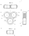
Fig. 1 (position of closing) in longitudinal section has shown the schematic diagram being arranged in the monolever mixing drum in the utensil of lateral row outlet;
Fig. 2 has shown the monolever mixing drum in Fig. 1 in the position of opening;
Fig. 3 has shown the schematic diagram of the head member of the mixing drum in Fig. 1
A) in longitudinal section
B) in cut-away section, (rotated 90 °),
C) in cross section;
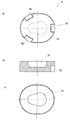
Fig. 4 has shown the diagram of the base member of the mixing drum in Fig. 1
A) in plan view,
B) in longitudinal section,
C) the view from below,
D) at b) in illustrated section D-D in,
E) in side view,
F) in side direction view, (rotated 90 °),
G) at b) in illustrated section B-B in,
H) at b) in illustrated section C-C in,
I) at b) in illustrated cross section A-A in;
Fig. 5 has shown the diagram of the sealing lip drip molding of the mixing drum in Fig. 1
A) in plan view,
B) in the illustrated cross section A-A in a),
In the illustrated section B-B of c in a),
D) in cross section;
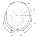
Fig. 6 has shown the diagram of passing through dish of the mixing drum in Fig. 1
A) the view from below,
B) in cross section,
C) in plan view;
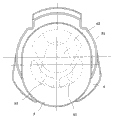
Fig. 7 has shown the diagram of the control panel of the mixing drum in Fig. 1
A) the view from below,
B) in cross section,
C) in plan view;
Fig. 8 has shown the diagram of the slide block of the mixing drum in Fig. 1
A) the view from below,
B) in cross section,
C) in plan view;
Fig. 9 has shown the dish control device of the mixing drum with control panel and in the Fig. 1 that passes through to coil in position " is closed ";
Figure 10 has shown the dish control device in the Fig. 9 in position " mixing water ";
Figure 11 has shown the dish control device in the Fig. 9 in position " cold water ";
Figure 12 has shown the axle accommodating part of the mixing drum in Fig. 1
A) the view from below,
B) in cross section,
C) in plan view;
Figure 13 has shown the axle of the mixing drum in Fig. 1
A) in side view,
B) in front view,
C) in plan view;
Figure 14 has shown the retaining ring of the mixing drum in Fig. 1
A) in cut-away view,
B) in plan view and
Figure 15 has shown the utensil of the layout in Fig. 1
A) the view from below,
B) in cut-away view,
C) in plan view.
Embodiment
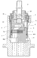
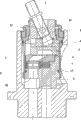
The monolever mixing drum of electing embodiment as mainly comprises head member 1, axle 2 axially stretches into wherein, axle 2 is bearing in swingably in rotatably mounted axle accommodating part 3 and engages in slide block 4, slide block 4 is connected with control panel 5, control panel 5, with corresponding by dish 6, seals base member 8 via seal molding part by coiling 6.
In addition, on the intercept 15 that the diameter that retaining ring 16 covers head member 1 reduces.Retaining ring 16 has for being screwed into the first outside thread 161 of utensil 9 around ground outside.On the first outside thread 161, be furnished with the convex shoulder 162 that diameter reduces, it is provided with the second outside thread 163.Distolateral, at retaining ring 16 places, be molded with the intercept 164 that diameter reduces, by it, form backstop 165.The intercept 164 that diameter reduces is provided with outer Hexagon 166 outside.The end relative at its intercept reducing with diameter 164 is molded with nose 167 around ground interior in addition in retaining ring 16.
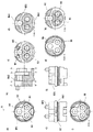
The slide block 4 that is embodied as moulding is shown greatly the form of disk and is constructed, and is molded with the moulded parts 41 of general square shape thereon.Moulded parts 41 is configured so that it is removable and guide in the horizontal in the vertical in the accommodating part 35 of axle accommodating part 3.Axially by slide block 4, through moulded parts 41 ground, introduce for holding the slotted hole 42 of the control head 24 of axle 2.At its downside place contrary with moulded parts 41, outside being in, slide block 4 is molded with in addition for holding three axial contact pin 43 of control panel 5 around ground.
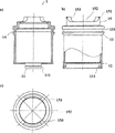
By coiling 6, be embodied as equally ceramic fitting.By by coiling 6 introducings for two inlet passages 61 of the water of cold or heat and increasing tectonic discharge route 62 for mixing water with respect to it.Inlet passage 61 and discharge route 62 favour by coiling 6 ground guiding through it.In side direction by Pan6Chu, be misplaced introduce be useful on base member 8 form fit three recesses (Aussparung) 63 of being connected.
In side direction, at base member 8 places, around ground, be molded with convex shoulder 86, for holding two recesses 861 of the contact pin 11 of head member 1, on diameter, relatively introduce wherein.In the region of recess 861, be molded with for joining the kayser nose 862 of latch groove 111 of the contact pin 11 of head member 1 to.These kayser noses 862 make the kayser between base member 8 and head member 1 be connected to become possibility.Around convex shoulder 86 on, around ground, introduce to be useful on and hold for making base member 8 with respect to the groove 87 of the O shape ring 871 of head member 1 sealing.On the upside of putting the relative with convex shoulder 83 of it, base member has the accommodating part 88 for the clover shape of seal molding part 7.Around accommodating part 88, homogeneous phase compartment of terrain is molded with for by coiling antitorque three contact pin 89 holding of 6 each other.Contact pin 89 joins to by coiling in 6 recess 63.In order to improve form fit, at two contact pin 89 places, be molded with nose 891, it joins to by coiling in 6 corresponding recess 63.
In Fig. 9 to 11, schematically show by control panel 5 with by the diverse location of the dish 6 dish control devices that form.According in the position of Fig. 9, by coiling 6 inlet passage 61, by the reentrant part 51 of control panel 5, hidden.Therefore inlet passage 61 is sealed by control panel 5.Do not produce water through-flow (position of closing).
According in the position of the dish control device of Figure 10, for two inlet passages 61 of hot water and cold water, by the reentrant part 51 of control panel 5, hidden, it also hides by the discharge route 62 of dish 6 simultaneously.Before mixing water flows out by the discharge route 62 by dish 6, in the interior generation hot water of reentrant part 51 of control panel 5 and the mixing of cold water.According in the position of the dish control device of Figure 11, only an inlet passage 61 (cold water inlet here) is hidden by the reentrant part 51 of control panel 5, its by this inlet passage 61 with by coiling 6 discharge route 62, be connected.Therefore only cold water flows out from the discharge route 82 of base member 8.
In Fig. 2, shown the assembly with dish control device according to Figure 10.Mixing water is discharged to the gap of formation between the cylinder accommodating part 91 of utensil 9 and head member 1 by passage 851 and arrives thus the drainage interface 94 and 96 of utensil 9 from the discharge route 82 of base member 8.According to the desirable design of utensil, therefore allow to remove mixing water by drainage interface 96 side direction, and allow to take out in bottom side water.Mixing drum itself by the water flowing out from base member 8 in the cylinder accommodating part 91 of utensil 9 around washing away.By being arranged in the kayser being formed between the latch groove 111 of head member 1 and the kayser nose 862 of base member 8, being connected O shape below ring 17 and effectively preventing that mixing water from entering at base member 8 and being arranged in the region after control simulation portion there.The possible distortion of the base member 8 being made of plastics is absorbed by O shape ring.By by brass structure head member 1, especially in the region of base member 8, avoid the distortion of head member 1.
The control of the current that flow out from the tap hole 82 of base member 8 realizes via axle 2.Axle 2 around the swing of pivot pin 23, via control head 24, be passed on slide block 4 and to slide block form fit on the control panel 5 that is connected, cause thus the control of the water yield.The rotation of axle 2 is passed on axle accommodating part 3 rotatably mounted in head member 1 via pivot pin 23, its with slide block 4 via moulded parts 41 form fit be connected.By rotatablely moving, be delivered to thus on slide block 4 and therefore to its form fit on the control panel 5 that is connected and cause and be present in by coiling the adjusting of proportions of ingredients of the current at 6 inlet passage 61 places.
Mixing drum is connected with utensil 9 via retaining ring 16 and the bottom pretension to cylinder accommodating part 91.Thus obtained pretightening force causes the balance of the manufacturing tolerances of each member (especially at slide block 4, control panel 5, by dish 6 and base member 8 places).Cause thus, can cause the inhomogeneous pressing force to seal molding part 7 between dish 6 and the base member on opposite side 8 that passes through in a side.By the flexible structure of seal molding part 7 with being molded in the sealing lip 72 at its place, the adjustment of 88Nei position becomes possibility in the accommodating part of base member 8 to make seal molding part 7, guarantees thus reliable sealing effect.Sealing effect is supported by the sealing lip 72 washing away in the back with water.The distortion of the ring 71 of seal molding part 7 (it can cause damaging sealing effect) is prevented by the support ring 73 of introducing in ring 71.
Retaining ring 16 cover is put on the intercept 15 that the diameter of head member 1 reduces, wherein, around nose 151 through retaining ring 16 around nose 167 time flexibly inwardly squeezed.After the process nose 167 of retaining ring 16, the nose 151 of the intercept 15 that the diameter of head member 1 reduces has occupied again its home position.Therefore retaining ring 16 prevents loss and remains on head member 1 place.Being screwed into via outer Hexagon 166 of retaining ring 16 realizes.Via the second outside thread 163 of retaining ring 16, make utensil 9 for example another housing member fixedly become possibility.
Claims (10)
1. a monolever mixing drum, it comprises: head member (1), it holds base member (8); And with the dish control device of control panel (5), its axle (2) via supporting at least is swingably arranged movably, wherein, described base member (8) seals via seal element with respect to described head member (1), it is characterized in that, in described base member (8), introduce one, preferably two inlet passages (81) and discharge route (82), wherein, described base member (8) has axial convex shoulder (83), and only described inlet passage (81) is guided through described convex shoulder (83).
2. monolever mixing drum according to claim 1, is characterized in that, described control panel (5) rotatably and is movably arranged via the axle (2) of rotatably and swingably supporting.
3. monolever mixing drum according to claim 1 and 2, is characterized in that, described seal element is formed by O shape ring (871).
4. according to monolever mixing drum in any one of the preceding claims wherein, it is characterized in that, described base member (8) has at least partly the kayser nose (862) around ground structure, latch groove (111) the phase kayser that it is interior with being arranged in described head member (1).
5. monolever mixing drum according to claim 4, is characterized in that, in axial described convex shoulder (83), around ground, radially introduces and has groove (831) at least partly.
6. according to the monolever mixing drum described in claim 4 or 5, it is characterized in that, be adjacent to axial described convex shoulder (83) and be furnished with at least one leg (85).
7. monolever mixing drum according to claim 6, is characterized in that, is molded with locating stud (852) on leg described at least one (83).
8. according to the monolever mixing drum described in claim 6 or 7, it is characterized in that, around described inlet passage (81), be furnished with the Sealing that axle protrudes upward.
9. according to monolever mixing drum in any one of the preceding claims wherein, it is characterized in that, described head member (1) is by metal, preferably brass is made.
10. according to monolever mixing drum in any one of the preceding claims wherein, it is characterized in that, described base member (8) is made of plastics.
Applications Claiming Priority (3)
| Application Number | Priority Date | Filing Date | Title |
|---|---|---|---|
| EP20120157384 EP2634463B1 (en) | 2012-02-28 | 2012-02-28 | Single hand lever mixer cartridge |
| EP12157384.4 | 2012-02-28 | ||
| PCT/EP2013/052157 WO2013127601A1 (en) | 2012-02-28 | 2013-02-04 | Single-lever mixing cartridge |
Publications (2)
| Publication Number | Publication Date |
|---|---|
| CN103703295A true CN103703295A (en) | 2014-04-02 |
| CN103703295B CN103703295B (en) | 2016-12-07 |
Family
ID=47740909
Family Applications (1)
| Application Number | Title | Priority Date | Filing Date |
|---|---|---|---|
| CN201380001401.2A Active CN103703295B (en) | 2012-02-28 | 2013-02-04 | Monolever mixing drum |
Country Status (9)
| Country | Link |
|---|---|
| US (1) | US9115819B2 (en) |
| EP (1) | EP2634463B1 (en) |
| KR (1) | KR102013965B1 (en) |
| CN (1) | CN103703295B (en) |
| AU (1) | AU2013225318B2 (en) |
| BR (1) | BR112013029791B1 (en) |
| MX (1) | MX336420B (en) |
| RU (1) | RU2602711C2 (en) |
| WO (1) | WO2013127601A1 (en) |
Families Citing this family (6)
| Publication number | Priority date | Publication date | Assignee | Title |
|---|---|---|---|---|
| EP2962021B1 (en) * | 2013-09-13 | 2017-08-02 | Flühs Drehtechnik GmbH | One-hand lever cartridge |
| HUE033173T2 (en) | 2015-02-25 | 2017-11-28 | Fluehs Drehtechnik Gmbh | Single hand lever cartridge |
| DE202015100918U1 (en) | 2015-02-25 | 2015-03-27 | Flühs Drehtechnik GmbH | Single lever cartridge |
| RU168591U1 (en) * | 2016-09-02 | 2017-02-09 | Общество с ограниченной ответственностью ПК "СВЕС" | SINGLE MIXING CARTRIDGE NUT |
| DE102017216413B3 (en) | 2017-09-15 | 2018-11-08 | Hansgrohe Se | Fluidumsteller |
| US11149418B2 (en) * | 2019-02-22 | 2021-10-19 | Brasstech, Inc. | Faucet handle hub |
Citations (6)
| Publication number | Priority date | Publication date | Assignee | Title |
|---|---|---|---|---|
| DE3518698A1 (en) * | 1985-05-24 | 1986-11-27 | Friedrich Grohe Armaturenfabrik Gmbh & Co, 5870 Hemer | Mixing valve for one-handed operation |
| US4887642A (en) * | 1987-10-27 | 1989-12-19 | Dorf Industries Pty. Ltd. | Single handle mixing tap or valve |
| US5095934A (en) * | 1991-04-16 | 1992-03-17 | Kohler Co. | Fluid valve |
| US5375624A (en) * | 1992-09-16 | 1994-12-27 | Masco Corporation Of Indiana | Cartridge for single-control faucet |
| CN2385175Y (en) * | 1999-07-05 | 2000-06-28 | 张家博 | Structure-improved water supply control valve ceramic dished sheet |
| CN1671985A (en) * | 2002-08-19 | 2005-09-21 | 东陶机器株式会社 | Disk valve |
Family Cites Families (8)
| Publication number | Priority date | Publication date | Assignee | Title |
|---|---|---|---|---|
| FI65659C (en) * | 1980-10-30 | 1984-06-11 | Oras Oy | ENGREPPSBLANDNINGSVENTIL |
| DE3419209C2 (en) * | 1984-05-23 | 1996-06-13 | Grohe Kg Hans | Mixing valve |
| IL73930A (en) * | 1984-12-25 | 1988-12-30 | Hamat Koor Metals Ltd | Mixing device for faucets |
| IT1213318B (en) * | 1986-07-31 | 1989-12-20 | Stella Rubinetterie Spa | SINGLE-LEVER MIXER TAP FOR WATER, WITH MEANS, FOR ADJUSTING THE END OF THE MIXING TEMPERATURE. |
| ITMI20022328A1 (en) * | 2002-10-31 | 2004-05-01 | Carlo Nobili S P A Rubinetterie | MIXING CARTRIDGE FOR SINGLE LEVER MIXER TAPS |
| US6920899B2 (en) * | 2003-03-27 | 2005-07-26 | Masco Corporation Of Indiana | Fluid control valve |
| US7032272B2 (en) * | 2003-03-27 | 2006-04-25 | Masco Corporation Of Indiana | Friction hinge |
| DE102008000108A1 (en) * | 2008-01-21 | 2009-07-23 | Ceramtec Ag | Cartridge for a sanitary fitting |
-
2012
- 2012-02-28 EP EP20120157384 patent/EP2634463B1/en active Active
-
2013
- 2013-02-04 KR KR1020137028668A patent/KR102013965B1/en active IP Right Grant
- 2013-02-04 CN CN201380001401.2A patent/CN103703295B/en active Active
- 2013-02-04 RU RU2013151615/06A patent/RU2602711C2/en active
- 2013-02-04 BR BR112013029791-3A patent/BR112013029791B1/en not_active IP Right Cessation
- 2013-02-04 AU AU2013225318A patent/AU2013225318B2/en not_active Ceased
- 2013-02-04 WO PCT/EP2013/052157 patent/WO2013127601A1/en active Application Filing
- 2013-02-04 US US14/117,966 patent/US9115819B2/en active Active
- 2013-02-04 MX MX2013013232A patent/MX336420B/en unknown
Patent Citations (6)
| Publication number | Priority date | Publication date | Assignee | Title |
|---|---|---|---|---|
| DE3518698A1 (en) * | 1985-05-24 | 1986-11-27 | Friedrich Grohe Armaturenfabrik Gmbh & Co, 5870 Hemer | Mixing valve for one-handed operation |
| US4887642A (en) * | 1987-10-27 | 1989-12-19 | Dorf Industries Pty. Ltd. | Single handle mixing tap or valve |
| US5095934A (en) * | 1991-04-16 | 1992-03-17 | Kohler Co. | Fluid valve |
| US5375624A (en) * | 1992-09-16 | 1994-12-27 | Masco Corporation Of Indiana | Cartridge for single-control faucet |
| CN2385175Y (en) * | 1999-07-05 | 2000-06-28 | 张家博 | Structure-improved water supply control valve ceramic dished sheet |
| CN1671985A (en) * | 2002-08-19 | 2005-09-21 | 东陶机器株式会社 | Disk valve |
Also Published As
| Publication number | Publication date |
|---|---|
| BR112013029791A2 (en) | 2017-01-31 |
| BR112013029791B1 (en) | 2021-05-18 |
| MX2013013232A (en) | 2014-05-27 |
| US20140090722A1 (en) | 2014-04-03 |
| AU2013225318B2 (en) | 2016-12-15 |
| EP2634463A1 (en) | 2013-09-04 |
| RU2602711C2 (en) | 2016-11-20 |
| KR102013965B1 (en) | 2019-08-23 |
| US9115819B2 (en) | 2015-08-25 |
| MX336420B (en) | 2016-01-19 |
| RU2013151615A (en) | 2015-05-27 |
| KR20140126659A (en) | 2014-10-31 |
| CN103703295B (en) | 2016-12-07 |
| EP2634463B1 (en) | 2014-05-14 |
| AU2013225318A1 (en) | 2013-11-07 |
| WO2013127601A1 (en) | 2013-09-06 |
Similar Documents
| Publication | Publication Date | Title |
|---|---|---|
| CN103703295A (en) | Single-lever mixing cartridge | |
| US10459463B2 (en) | Water flow control valve | |
| US9931606B2 (en) | Single-lever mixing cartridge | |
| US10086390B2 (en) | Multi-function sprayhead | |
| US9033001B2 (en) | Water divider | |
| US8875737B2 (en) | High performance single control lever mixing cartridge | |
| CN107061773B (en) | Faucet assembly | |
| US8567429B2 (en) | Faucet with a replaceable control valve | |
| TW201734345A (en) | Hot and cold water mixing faucet | |
| KR102013000B1 (en) | Single-lever mixing cartridge | |
| CN109404560A (en) | The thermostatic valve core that temperature-sensitive is discharged after a kind of mixing of hot and cold water | |
| US20200318326A1 (en) | Fixing structure for water pipe of split type faucet body | |
| CN105190138A (en) | Single lever cartridge | |
| CN205026142U (en) | Three function diverter valves | |
| CN204805614U (en) | Bathroom mixing faucet spare | |
| CN109340393A (en) | A kind of flow control valve core | |
| CN108474486B (en) | Hot water combustion taps fluid control valve apparatus | |
| CN101639130B (en) | Knob valve core | |
| CN211259792U (en) | Shower faucet valve body | |
| CN108369426A (en) | Thermostatic valve core for controlling hot fluid to be mixed and cold fluid | |
| CN107250633B (en) | Valve upper-part | |
| CN219366891U (en) | Cold touch type multifunctional waterway switching thermostat | |
| KR200492788Y1 (en) | Side lever type faucet cartridge | |
| CN204267791U (en) | A kind of thermostatic switch modulating valve | |
| CN211202980U (en) | Convenient to use's constant temperature shower faucet |
Legal Events
| Date | Code | Title | Description |
|---|---|---|---|
| C06 | Publication | ||
| PB01 | Publication | ||
| C10 | Entry into substantive examination | ||
| SE01 | Entry into force of request for substantive examination | ||
| C14 | Grant of patent or utility model | ||
| GR01 | Patent grant |