CN103237525A - Systems for facet joint treatment - Google Patents
Systems for facet joint treatment Download PDFInfo
- Publication number
- CN103237525A CN103237525A CN2011800389495A CN201180038949A CN103237525A CN 103237525 A CN103237525 A CN 103237525A CN 2011800389495 A CN2011800389495 A CN 2011800389495A CN 201180038949 A CN201180038949 A CN 201180038949A CN 103237525 A CN103237525 A CN 103237525A
- Authority
- CN
- China
- Prior art keywords
- facet joint
- implant
- engaging structure
- instrument
- tusk
- Prior art date
- Legal status (The legal status is an assumption and is not a legal conclusion. Google has not performed a legal analysis and makes no representation as to the accuracy of the status listed.)
- Pending
Links
Images


Classifications
-
- A—HUMAN NECESSITIES
- A61—MEDICAL OR VETERINARY SCIENCE; HYGIENE
- A61B—DIAGNOSIS; SURGERY; IDENTIFICATION
- A61B17/00—Surgical instruments, devices or methods, e.g. tourniquets
- A61B17/56—Surgical instruments or methods for treatment of bones or joints; Devices specially adapted therefor
- A61B17/58—Surgical instruments or methods for treatment of bones or joints; Devices specially adapted therefor for osteosynthesis, e.g. bone plates, screws, setting implements or the like
- A61B17/68—Internal fixation devices, including fasteners and spinal fixators, even if a part thereof projects from the skin
- A61B17/70—Spinal positioners or stabilisers ; Bone stabilisers comprising fluid filler in an implant
- A61B17/7062—Devices acting on, attached to, or simulating the effect of, vertebral processes, vertebral facets or ribs ; Tools for such devices
- A61B17/7067—Devices bearing against one or more spinous processes and also attached to another part of the spine; Tools therefor
-
- A—HUMAN NECESSITIES
- A61—MEDICAL OR VETERINARY SCIENCE; HYGIENE
- A61F—FILTERS IMPLANTABLE INTO BLOOD VESSELS; PROSTHESES; DEVICES PROVIDING PATENCY TO, OR PREVENTING COLLAPSING OF, TUBULAR STRUCTURES OF THE BODY, e.g. STENTS; ORTHOPAEDIC, NURSING OR CONTRACEPTIVE DEVICES; FOMENTATION; TREATMENT OR PROTECTION OF EYES OR EARS; BANDAGES, DRESSINGS OR ABSORBENT PADS; FIRST-AID KITS
- A61F2/00—Filters implantable into blood vessels; Prostheses, i.e. artificial substitutes or replacements for parts of the body; Appliances for connecting them with the body; Devices providing patency to, or preventing collapsing of, tubular structures of the body, e.g. stents
- A61F2/02—Prostheses implantable into the body
- A61F2/30—Joints
- A61F2/44—Joints for the spine, e.g. vertebrae, spinal discs
-
- A—HUMAN NECESSITIES
- A61—MEDICAL OR VETERINARY SCIENCE; HYGIENE
- A61B—DIAGNOSIS; SURGERY; IDENTIFICATION
- A61B18/00—Surgical instruments, devices or methods for transferring non-mechanical forms of energy to or from the body
- A61B18/04—Surgical instruments, devices or methods for transferring non-mechanical forms of energy to or from the body by heating
- A61B18/12—Surgical instruments, devices or methods for transferring non-mechanical forms of energy to or from the body by heating by passing a current through the tissue to be heated, e.g. high-frequency current
- A61B18/14—Probes or electrodes therefor
- A61B18/16—Indifferent or passive electrodes for grounding
-
- A—HUMAN NECESSITIES
- A61—MEDICAL OR VETERINARY SCIENCE; HYGIENE
- A61B—DIAGNOSIS; SURGERY; IDENTIFICATION
- A61B18/00—Surgical instruments, devices or methods for transferring non-mechanical forms of energy to or from the body
- A61B18/18—Surgical instruments, devices or methods for transferring non-mechanical forms of energy to or from the body by applying electromagnetic radiation, e.g. microwaves
-
- A—HUMAN NECESSITIES
- A61—MEDICAL OR VETERINARY SCIENCE; HYGIENE
- A61F—FILTERS IMPLANTABLE INTO BLOOD VESSELS; PROSTHESES; DEVICES PROVIDING PATENCY TO, OR PREVENTING COLLAPSING OF, TUBULAR STRUCTURES OF THE BODY, e.g. STENTS; ORTHOPAEDIC, NURSING OR CONTRACEPTIVE DEVICES; FOMENTATION; TREATMENT OR PROTECTION OF EYES OR EARS; BANDAGES, DRESSINGS OR ABSORBENT PADS; FIRST-AID KITS
- A61F2/00—Filters implantable into blood vessels; Prostheses, i.e. artificial substitutes or replacements for parts of the body; Appliances for connecting them with the body; Devices providing patency to, or preventing collapsing of, tubular structures of the body, e.g. stents
- A61F2/02—Prostheses implantable into the body
- A61F2/30—Joints
- A61F2/44—Joints for the spine, e.g. vertebrae, spinal discs
- A61F2/4405—Joints for the spine, e.g. vertebrae, spinal discs for apophyseal or facet joints, i.e. between adjacent spinous or transverse processes
-
- A—HUMAN NECESSITIES
- A61—MEDICAL OR VETERINARY SCIENCE; HYGIENE
- A61F—FILTERS IMPLANTABLE INTO BLOOD VESSELS; PROSTHESES; DEVICES PROVIDING PATENCY TO, OR PREVENTING COLLAPSING OF, TUBULAR STRUCTURES OF THE BODY, e.g. STENTS; ORTHOPAEDIC, NURSING OR CONTRACEPTIVE DEVICES; FOMENTATION; TREATMENT OR PROTECTION OF EYES OR EARS; BANDAGES, DRESSINGS OR ABSORBENT PADS; FIRST-AID KITS
- A61F2/00—Filters implantable into blood vessels; Prostheses, i.e. artificial substitutes or replacements for parts of the body; Appliances for connecting them with the body; Devices providing patency to, or preventing collapsing of, tubular structures of the body, e.g. stents
- A61F2/02—Prostheses implantable into the body
- A61F2/30—Joints
- A61F2/46—Special tools or methods for implanting or extracting artificial joints, accessories, bone grafts or substitutes, or particular adaptations therefor
- A61F2/4603—Special tools or methods for implanting or extracting artificial joints, accessories, bone grafts or substitutes, or particular adaptations therefor for insertion or extraction of endoprosthetic joints or of accessories thereof
- A61F2/4611—Special tools or methods for implanting or extracting artificial joints, accessories, bone grafts or substitutes, or particular adaptations therefor for insertion or extraction of endoprosthetic joints or of accessories thereof of spinal prostheses
-
- A—HUMAN NECESSITIES
- A61—MEDICAL OR VETERINARY SCIENCE; HYGIENE
- A61F—FILTERS IMPLANTABLE INTO BLOOD VESSELS; PROSTHESES; DEVICES PROVIDING PATENCY TO, OR PREVENTING COLLAPSING OF, TUBULAR STRUCTURES OF THE BODY, e.g. STENTS; ORTHOPAEDIC, NURSING OR CONTRACEPTIVE DEVICES; FOMENTATION; TREATMENT OR PROTECTION OF EYES OR EARS; BANDAGES, DRESSINGS OR ABSORBENT PADS; FIRST-AID KITS
- A61F2/00—Filters implantable into blood vessels; Prostheses, i.e. artificial substitutes or replacements for parts of the body; Appliances for connecting them with the body; Devices providing patency to, or preventing collapsing of, tubular structures of the body, e.g. stents
- A61F2/02—Prostheses implantable into the body
- A61F2/30—Joints
- A61F2002/30001—Additional features of subject-matter classified in A61F2/28, A61F2/30 and subgroups thereof
- A61F2002/30003—Material related properties of the prosthesis or of a coating on the prosthesis
- A61F2002/3006—Properties of materials and coating materials
- A61F2002/3008—Properties of materials and coating materials radio-opaque, e.g. radio-opaque markers
-
- A—HUMAN NECESSITIES
- A61—MEDICAL OR VETERINARY SCIENCE; HYGIENE
- A61F—FILTERS IMPLANTABLE INTO BLOOD VESSELS; PROSTHESES; DEVICES PROVIDING PATENCY TO, OR PREVENTING COLLAPSING OF, TUBULAR STRUCTURES OF THE BODY, e.g. STENTS; ORTHOPAEDIC, NURSING OR CONTRACEPTIVE DEVICES; FOMENTATION; TREATMENT OR PROTECTION OF EYES OR EARS; BANDAGES, DRESSINGS OR ABSORBENT PADS; FIRST-AID KITS
- A61F2/00—Filters implantable into blood vessels; Prostheses, i.e. artificial substitutes or replacements for parts of the body; Appliances for connecting them with the body; Devices providing patency to, or preventing collapsing of, tubular structures of the body, e.g. stents
- A61F2/02—Prostheses implantable into the body
- A61F2/30—Joints
- A61F2002/30001—Additional features of subject-matter classified in A61F2/28, A61F2/30 and subgroups thereof
- A61F2002/30316—The prosthesis having different structural features at different locations within the same prosthesis; Connections between prosthetic parts; Special structural features of bone or joint prostheses not otherwise provided for
- A61F2002/30317—The prosthesis having different structural features at different locations within the same prosthesis
- A61F2002/30321—The prosthesis having different structural features at different locations within the same prosthesis differing in roughness
-
- A—HUMAN NECESSITIES
- A61—MEDICAL OR VETERINARY SCIENCE; HYGIENE
- A61F—FILTERS IMPLANTABLE INTO BLOOD VESSELS; PROSTHESES; DEVICES PROVIDING PATENCY TO, OR PREVENTING COLLAPSING OF, TUBULAR STRUCTURES OF THE BODY, e.g. STENTS; ORTHOPAEDIC, NURSING OR CONTRACEPTIVE DEVICES; FOMENTATION; TREATMENT OR PROTECTION OF EYES OR EARS; BANDAGES, DRESSINGS OR ABSORBENT PADS; FIRST-AID KITS
- A61F2/00—Filters implantable into blood vessels; Prostheses, i.e. artificial substitutes or replacements for parts of the body; Appliances for connecting them with the body; Devices providing patency to, or preventing collapsing of, tubular structures of the body, e.g. stents
- A61F2/02—Prostheses implantable into the body
- A61F2/30—Joints
- A61F2002/30001—Additional features of subject-matter classified in A61F2/28, A61F2/30 and subgroups thereof
- A61F2002/30316—The prosthesis having different structural features at different locations within the same prosthesis; Connections between prosthetic parts; Special structural features of bone or joint prostheses not otherwise provided for
- A61F2002/30317—The prosthesis having different structural features at different locations within the same prosthesis
- A61F2002/30322—The prosthesis having different structural features at different locations within the same prosthesis differing in surface structures
-
- A—HUMAN NECESSITIES
- A61—MEDICAL OR VETERINARY SCIENCE; HYGIENE
- A61F—FILTERS IMPLANTABLE INTO BLOOD VESSELS; PROSTHESES; DEVICES PROVIDING PATENCY TO, OR PREVENTING COLLAPSING OF, TUBULAR STRUCTURES OF THE BODY, e.g. STENTS; ORTHOPAEDIC, NURSING OR CONTRACEPTIVE DEVICES; FOMENTATION; TREATMENT OR PROTECTION OF EYES OR EARS; BANDAGES, DRESSINGS OR ABSORBENT PADS; FIRST-AID KITS
- A61F2/00—Filters implantable into blood vessels; Prostheses, i.e. artificial substitutes or replacements for parts of the body; Appliances for connecting them with the body; Devices providing patency to, or preventing collapsing of, tubular structures of the body, e.g. stents
- A61F2/02—Prostheses implantable into the body
- A61F2/30—Joints
- A61F2002/30001—Additional features of subject-matter classified in A61F2/28, A61F2/30 and subgroups thereof
- A61F2002/30316—The prosthesis having different structural features at different locations within the same prosthesis; Connections between prosthetic parts; Special structural features of bone or joint prostheses not otherwise provided for
- A61F2002/30317—The prosthesis having different structural features at different locations within the same prosthesis
- A61F2002/30324—The prosthesis having different structural features at different locations within the same prosthesis differing in thickness
-
- A—HUMAN NECESSITIES
- A61—MEDICAL OR VETERINARY SCIENCE; HYGIENE
- A61F—FILTERS IMPLANTABLE INTO BLOOD VESSELS; PROSTHESES; DEVICES PROVIDING PATENCY TO, OR PREVENTING COLLAPSING OF, TUBULAR STRUCTURES OF THE BODY, e.g. STENTS; ORTHOPAEDIC, NURSING OR CONTRACEPTIVE DEVICES; FOMENTATION; TREATMENT OR PROTECTION OF EYES OR EARS; BANDAGES, DRESSINGS OR ABSORBENT PADS; FIRST-AID KITS
- A61F2/00—Filters implantable into blood vessels; Prostheses, i.e. artificial substitutes or replacements for parts of the body; Appliances for connecting them with the body; Devices providing patency to, or preventing collapsing of, tubular structures of the body, e.g. stents
- A61F2/02—Prostheses implantable into the body
- A61F2/30—Joints
- A61F2002/30001—Additional features of subject-matter classified in A61F2/28, A61F2/30 and subgroups thereof
- A61F2002/30667—Features concerning an interaction with the environment or a particular use of the prosthesis
- A61F2002/30682—Means for preventing migration of particles released by the joint, e.g. wear debris or cement particles
- A61F2002/30685—Means for reducing or preventing the generation of wear particulates
-
- A—HUMAN NECESSITIES
- A61—MEDICAL OR VETERINARY SCIENCE; HYGIENE
- A61F—FILTERS IMPLANTABLE INTO BLOOD VESSELS; PROSTHESES; DEVICES PROVIDING PATENCY TO, OR PREVENTING COLLAPSING OF, TUBULAR STRUCTURES OF THE BODY, e.g. STENTS; ORTHOPAEDIC, NURSING OR CONTRACEPTIVE DEVICES; FOMENTATION; TREATMENT OR PROTECTION OF EYES OR EARS; BANDAGES, DRESSINGS OR ABSORBENT PADS; FIRST-AID KITS
- A61F2/00—Filters implantable into blood vessels; Prostheses, i.e. artificial substitutes or replacements for parts of the body; Appliances for connecting them with the body; Devices providing patency to, or preventing collapsing of, tubular structures of the body, e.g. stents
- A61F2/02—Prostheses implantable into the body
- A61F2/30—Joints
- A61F2/30721—Accessories
- A61F2002/30754—Implants for interposition between two natural articular surfaces
-
- A—HUMAN NECESSITIES
- A61—MEDICAL OR VETERINARY SCIENCE; HYGIENE
- A61F—FILTERS IMPLANTABLE INTO BLOOD VESSELS; PROSTHESES; DEVICES PROVIDING PATENCY TO, OR PREVENTING COLLAPSING OF, TUBULAR STRUCTURES OF THE BODY, e.g. STENTS; ORTHOPAEDIC, NURSING OR CONTRACEPTIVE DEVICES; FOMENTATION; TREATMENT OR PROTECTION OF EYES OR EARS; BANDAGES, DRESSINGS OR ABSORBENT PADS; FIRST-AID KITS
- A61F2/00—Filters implantable into blood vessels; Prostheses, i.e. artificial substitutes or replacements for parts of the body; Appliances for connecting them with the body; Devices providing patency to, or preventing collapsing of, tubular structures of the body, e.g. stents
- A61F2/02—Prostheses implantable into the body
- A61F2/30—Joints
- A61F2/30767—Special external or bone-contacting surface, e.g. coating for improving bone ingrowth
- A61F2/30771—Special external or bone-contacting surface, e.g. coating for improving bone ingrowth applied in original prostheses, e.g. holes or grooves
- A61F2002/30841—Sharp anchoring protrusions for impaction into the bone, e.g. sharp pins, spikes
-
- A—HUMAN NECESSITIES
- A61—MEDICAL OR VETERINARY SCIENCE; HYGIENE
- A61F—FILTERS IMPLANTABLE INTO BLOOD VESSELS; PROSTHESES; DEVICES PROVIDING PATENCY TO, OR PREVENTING COLLAPSING OF, TUBULAR STRUCTURES OF THE BODY, e.g. STENTS; ORTHOPAEDIC, NURSING OR CONTRACEPTIVE DEVICES; FOMENTATION; TREATMENT OR PROTECTION OF EYES OR EARS; BANDAGES, DRESSINGS OR ABSORBENT PADS; FIRST-AID KITS
- A61F2/00—Filters implantable into blood vessels; Prostheses, i.e. artificial substitutes or replacements for parts of the body; Appliances for connecting them with the body; Devices providing patency to, or preventing collapsing of, tubular structures of the body, e.g. stents
- A61F2/02—Prostheses implantable into the body
- A61F2/30—Joints
- A61F2/46—Special tools or methods for implanting or extracting artificial joints, accessories, bone grafts or substitutes, or particular adaptations therefor
- A61F2/4603—Special tools or methods for implanting or extracting artificial joints, accessories, bone grafts or substitutes, or particular adaptations therefor for insertion or extraction of endoprosthetic joints or of accessories thereof
- A61F2002/4629—Special tools or methods for implanting or extracting artificial joints, accessories, bone grafts or substitutes, or particular adaptations therefor for insertion or extraction of endoprosthetic joints or of accessories thereof connected to the endoprosthesis or implant via a threaded connection
Abstract
A system for treating a facet joint of a patient. The facet joint includes a superior articular face and an inferior articular face. The system includes a resurfacing device, an implant insertion tool and a guide cannula. The resurfacing device is positionable between a superior articular face of a facet joint and an inferior articular face of a facet joint. The implant insertion tool is adapted to engage the resurfacing device. The guide cannula has a passage extending therethrough. The guide cannula passage is adapted to receive at least a portion of the resurfacing device and the implant insertion tool.
Description
To quoting of related application
The application requires the priority of the U.S. Provisional Application submitted on June 15th, 2010 number 61/355,140, and the content of described provisional application is incorporated this paper by reference into.
Technical field
One embodiment of the invention relate to the system that is used for the treatment of the facet joint pain.More particularly, the present invention relates to be used for the treatment of the implant system of facet joint pain.
Background technology
In ensuing ten years, will there be 70,000,000 people of surpassing to add older's ranks.In the aging crowd, make skeleton relative to each other the articular cartilage of smooth motion can wear and tear along with time and disease, and as the many tissues in the consubstantiality, articular cartilage has limited self-healing ability.
At this moment, the selection that helps to alleviate severe degenerative arthralgia or osteoarthritis comprises joint replacement or fusion.For instance, carry out about 200,000 routine total knee replacements operation and surpass 300,000 routine hip replacement surgeries every year.Though these generally are that effectively these prosthetic joint implants are only enough kept about 10-15 when being chosen in the treatment diseased joints.
Chronic low back pain also influences labourer's productivity ratio and health care cost simultaneously.Current American surpasses 500 every year, 000 exception section operative procedure to be attempting to alleviate back pain, even these surgical procedure are only just carried out after comparatively conservative therapy (as lie up, pain and the slow medicine treatment of muscle, physiotherapy or steroid injection) failure usually.The source of this pain may be the dysfunction that originates from the multiple anatomical structure (as mentioned below) (comprising facet joint) that comprises in the spinal column.
For understanding the influence in therapy of spinal biomechanics and dysfunction, should at first consider the anatomy of spine structure.The vertebra of spinal column is subdivided into some sections as a rule.Mobile to coccyx (tail end) by head (head end), section is cervical vertebra, thoracic vertebra, lumbar vertebra, sacral and caudal vertebra.
No matter the position how, each vertebra all forms two pedicles of vertebral arch and two lamina of vertebral arch, and they make up to define intervertebral foramina, and spinal cord is protected therein.Two transverse process are extended laterally by pedicle of vertebral arch.Spinous process is extended by the vertebra midline of two lamina of vertebral arch intersections.These three projections are served as the junction point of ligament and muscle.
Adjacent vertebra is separated by intervertebral disc and the surface of adjacent vertebrae forms a part from two vertebras and the facet joint between two vertebras.About the spinal levels of being made up of intermediate vertebra, next-door neighbour's head end vertebra and next-door neighbour's tail end vertebra, intermediate vertebra forms the part of four facet joints, that is, two with the facet joint of head end vertebra and two facet joint with the tail end vertebra.
Consider above-mentioned background, the facet joint 20 that Figure 1A and Figure 1B explanation are made of superior articular facet 22 and inferior articular facet 24.Superior articular facet 22 forms (that is, superior articular facet is connect towards last projection by lamina of vertebral arch and pedicle of vertebral arch) by the vertebra face of intervertebral disc below, and inferior articular facet 24 forms (that is the downward projection of inferior articular facet) by the vertebra face above the intervertebral disc.
Superior articular surface 26 is positioned on the superior articular facet 22, and inferior articular surface 28 is positioned on the inferior articular facet 24.The orientation of facet joint and sagittal plane inclination and joint space itself are by crooked behind the forward direction.Being positioned at more that the inferior articular surface 28 of back is convex surface, is concave surfaces and be positioned at more inner superior articular surface 26.
The osteoarthrosis facet 22 of formation synovial fluid facet joint 20,24 end are covered by joint hyaline cartilage 30 usually, and described joint hyaline cartilage 30 allows bone faces 26,28 to slide relative to one another, thereby the motility that allows vertebral body relative to each other to move is provided.
As mentioned above, between each is to vertebra, there are two facet joints, from top and the bottom of each vertebra, one on each limit (being positioned at rear and the side of vertebra centrage).Described joint and intervertebral disc space are combined in and produce three joint complexs on each vertebra aspect, and each joint extension and overlapping adjacent vertebrae facet joint, thereby are connected to each other and therefore vertebra are linked together.
The combination of two vertebral bodys, intervenient intervertebral disc and the ligament that is connected, muscle and facet joints (engaging the below articular process of the top articular process of next the follow-up vertebra on the tail end direction) is called " spinal motion segment ".Each motion segment promotes the overall flexibility of spinal column and promotes the whole capability that spinal column provides support to the motion of trunk and head, and specifically, the facet joint restriction is reversed (distortion) and moved.
When the facet degradation of one or more vertebral bodys or otherwise sustain damage and cause vertebra no longer to be engaged with each other or each other suitably on time, can cause motor capacity decline and pain or discomfort.Therefore the functional effect of facet joint in spinal motion segment be with relevant to the understanding of the operation of facet joint system and method disclosed herein and function benefit, and described system and method disclosed herein is realized dynamic stability and motor capacity maintenance and do not limited motion on any plane.
As indicated above, facet joint is positioned on the rear pillar of spinal column.In the context of the present invention: " the place ahead " refers to the front at spinal column, and " rear " refers to the back at spinal column; " head end " means towards patient's head (being sometimes referred to as " top "), and " tail end " (being sometimes referred to as " below ") refers to direction or position near patient foot.
Facet joint may be because along with arthritis takes place in old and feeble, wound or disease (pathology that for example comprise struvite, metabolic or synovial fluid sexually transmitted disease (STD) disease) degeneration.In addition, fracture, laceration of ligament and disc problems (dehydration or formation hernia) can cause motion and aim at unusually, thereby extra pressure is caused on the surface of facet joint.
Physiological reaction to this extra pressure is to produce hyperosteogeny, i.e. bony spur.Along with form bony spur around the edge of facet joint, it is big that the joint becomes, i.e. a kind of condition of illness that is called hypertrophy, and final articular surface generation arthritis.When articular cartilage degeneration or wearing and tearing, the skeleton of below is exposed and the mutual friction of skeleton phase.Joint so inflammation, swelling and pain.
Facet joint arthritis is the important source of cervical region and back pain, and is attributable to the persistence back pain illness of about 15-30%.By under fluoroscopy is instructed, use such as intraarticular steroid/local anesthesia injection etc. facet joint pain is carried out conservative treatment failure after, some chronic pain patient may finally need be used for the arthritic surgical operation of facet joint and get involved, and comprise for example facet rhizotomy; Remove facet joint to reduce the facet excision to the pressure of outgoing nerve root; Total joint replacement or facet joint fusion (that is, what cause merging is fixing, wherein make two composition surfaces in joint keep fixing or firmly be grown in together and form single solid skeleton piece); Deng.
Although these surgical procedure can alleviate backache, many joint replacements and all fusions all can not recover to belong to physiological function and the motion of healthy anatomical form.On the contrary, their usually significantly change biomechanics of spinal column, this can then cause or other spinal column aspect that deterioration is relevant with spinal motion on or the qualitative and degeneration of unstable spine of the coexistence in other joint.
Between intervertebral disc integrity, facet load and spinal degeneration, there is cause effect relation.Specifically, disc height is along with the carrying out property reduction of disc degeneration also changes the mechanical ability of facet joint usually, because facet joint degeneration or dislocation, and the elasticity of ligament and its load-carrying ability reduce.More particularly, along with intervertebral disc space narrows down, this often follows degenerative disc disease to take place, and the load of (especially when stretching) increases in the facet joint, and follows the degeneration of facet joint and joint capsule.
Because the facet joint capsule is loaded when crooked and rotation, and facet joint is to the main impedance of anti-rotational force or twisting resistance (for example under normal conditions, facet joint is controlled about 30% axial rotation), so facet joint degeneration obviously changes the spinal motion ability.
For overall spinal motion ability, at first need to provide the minimum therapy of aggressive that makes pain relief recover simultaneously and keep the biomechanics function of physiology's facet joint, and up to now, there is not therapy fully to satisfy all these problems as yet, as mentioned below.
As a kind of therapy, the facet rhizotomy relates to the technology of cutting off the nervelet that goes to facet joint.The intention of described program is to stop the pain impulsion along the propagation of these nerves.Described neural the use diagnoses injection to be identified.Then, the surgeon inserts a big hollow pinhead and passes tissue in the lower back.Insert a rf probe by described syringe needle, and use cryptoscope that described probe is guided to described nerve.Probe heated lentamente until nerve be cut off.
Use another technology of pulse radiation frequency in fact not burn nerve, but it is neural to think that it hits.Another technology relates to by the freezing denervation that carries out of probe pinpoint; and another program relates under careful control the injection Botulinum toxin and treats muscle spasm, and described muscle spasm is for when facet inflammation and then the guarding reflex that may occur when causing near the muscle generation spasm parallel with muscle.
Though these programs can make pain relief, but it can not solve occurent degenerative joint (for example composition surface wearing and tearing), described degenerative joint causes kinesiology and biomechanics dysfunction, described obstacle transfers can cause conversion syndrome (that is, degeneration and pain develop into other joint) in other aspect again.
Though some clinicist advocates impaired facet joint is carried out the prosthese total joint replacement, but in fact, for a variety of reasons, be difficult to carry out this prosthese art, described reason comprises high-caliber interaction between other assembly in different and facet joint and the spinal column of facet joint geometry between facet joint and facet joint.
In addition, joint replacement is the invasive program consuming time of a kind of height, need prepare articular surface in advance and remove skeleton, and therefore have relevant risk, comprises losing blood and morbidity, anesthesia duration increase and increase recovery time.
The associated treatment processing of facet joint need provide artificial facet joint, wherein descend the last facet sections of facet sections, cooperation or both with medicated cap cover (that is, the whole of facet or basically all on).A kind of described device and relevant method for implantation are described in the U.S. Patent number Re36 of Fitz, in 758.
Though may be feasible, the facet sections is added medicated cap have some potential defects.Think that clinical problem is caused by the destruction of periosteum and ligament of head of femur (both plays a part to send nutrition to femoral head), causes the bone supporting structure of medicated cap avascular necrosis to occur thus.
Another potential defect that facet adds medicated cap is to adapting to not only between the individuality, and between intravertebral each aspect the extensive transmutability of facet anatomical structure form, need the medicated cap size and dimension of extremely wide scope.
Further, implant medicated cap (as U.S. Patent number Re36, those described in 758) and can not carry out in Wicresoft's mode, and in the ready step quite important (for example bone removes and/or shaping) of implant site.At least use under the situation of medicated cap at the osteoarthritic femoral head, the ossa articularia end is added medicated cap ride for a fall clinically because machinery is loosening sometimes.
Another therapeutic treatment of facet joint is to use the facet screw that the superior articular process is fixed on the inferior articular process.Although described immobilization treatment can alleviate the symptom relevant with the facet joint of degenerating, this has also sacrificed the ability of some motion segment motions and has therefore also sacrificed the ability that some spinal columns move in natural mode.
Central authorities and side direction spinal canal stenosis (joint constriction), degenerative spondylolisthesis and degenerative skoliosis may all result between the front and rear spine structure mechanical relation unusually and bring out weakness pain.
Recently, but developed the facet joint stabilising arrangement that percutaneous is implanted, and be described in U. S. application number 12/238, in 196 (JIUYUE in 2008 submission on the 25th and name are called " Method and Apparatus for Facet Joint Stabilization "), this paper is incorporated in the instruction of described application by reference into.The facet joint stabilising arrangement needs upper body and sub-body usually, and they form the external screw-thread device when combination.
In the time of in inserting the joint space, sub-body and upper body are set up meshing relation with respective lower and the top bone face of facet joint anatomical structure respectively, and can relative to each other slide to promote near normal facet joint motor capacity to a certain extent.Although feasible, but still remain with room for improvement, comprise maintenance, long-term function and insertion technology.
When the present invention expection optimization approach by coming from the percutaneous posterior approach during near various vertebral members and joint, " near-end " and " far-end " defines in the context of this passage of described approach.Therefore, " near-end " near passage begin the place and therefore near the clinicist, and " far-end " away from passage begin the place and therefore from the clinicist away from.
Approach or during means of delivery, " far-end " will be that desire is used for inserting the end near passage when mentioning, and " near-end " refers to opposite ends, normally near the end of the handle of means of delivery.When mentioning implant, in general, " far-end " will be at first to insert leading edge in the joint and " near-end " refers to the hangover end, generally mesh with deployment tool.
According to above, to being applicable to facet joint so that there are needs in adjunctive therapy stable and that strengthen facet joint, can not resort at the very start in order to alleviate problem with facet joint with prosthetic replacement and/or fixedly facet joint more radical therapy and do not have the intrinsic loss of the natural motion of described motion segment.
Summary of the invention
Aspects more of the present invention relate to the system of the facet joint that is used for the treatment of the patient.The facet joint anatomical structure comprises relative superior articular surface and inferior articular surface.In view of this, described system comprises upper surface trimming device and lower surface trimming device.
Upper surface trimming device has upper surface trimming body, and described upper surface trimming body is configured to the shape that selectivity is transformed into the shape of the superior articular surface that meets facet joint.Similarly, lower surface trimming device comprises lower surface trimming body, and described lower surface trimming body is configured to the shape that selectivity is transformed into the shape of the inferior articular surface that meets facet joint.
With regard to this point, each surface dressing body shows the enough flexibilities that become the insertion state by the state-transition of relatively flat, and wherein any many plain bendings that described surface dressing body mates corresponding facet joint articular surface basically in the presence of the compression stress relevant with typical adult's facet joint partly and concave surface.
Under this structure, described system can set up new sliding interface by the composition surface of surface dressing body in facet joint, thus interface, joint between the bone that causes pain of elimination and natural anatomic structurally associated.In addition, by meeting the natural shape relevant with natural facet joint articular surface, system of the present invention can Wicresoft's mode insert, and (for example removing) natural bone interface that do not need reconstruct.
In some embodiments, the surface dressing body is identical, and the discoid body in the scope of each free thickness between about 0.25 millimeter and about 4 millimeters is formed.In related embodiment, the surface dressing body is formed by the material based on polyether-ketone (PEK), such as or polyether-ether-ketone (PEEK).
In other embodiments, the surface dressing body provides composition surface and at the outstanding a plurality of tusks of the direction opposite with composition surface; Described a plurality of tusk is for the engagement of foundation after insertion with corresponding facet joint articular surface.
Other side relates to the method for the facet joint pain that is used for the treatment of the patient in accordance with the principles of the present invention, and comprise upper surface rebuild that body inserts in the facet joint and with the superior articular surface engagement of facet joint joint anatomical structure.With regard to this point, upper surface trimming body becomes the insertion state by the state-transition of relatively flat after inserting facet joint, thereby meets the shape of facet joint face basically in response to the compression stress of facet joint.
Lower surface is rebuild body to be inserted in the facet joint and with following facet joint articular surface and meshes.As the part of this insertion, lower surface trimming body becomes the insertion state that meets the shape of inferior articular surface in response to the compression stress of facet joint basically by the state-transition of relatively flat.
After final the insertion, the composition surface of upper surface trimming body alleviates the facet joint pain thus slidably in abutting connection with the composition surface of lower surface trimming body.In some embodiments, described method is characterised in that and does not exist operation to remove the normal bone of facet joint, and inserts described surface dressing body by the percutaneous technology simultaneously.
Other side relates to the external member of the facet joint that is used for the treatment of the patient in accordance with the principles of the present invention.Described external member comprises therapy system as indicated above (for example have the upper surface trimming device of upper surface trimming body and have the lower surface trimming device that lower surface is rebuild body) and inserts the tool group cover.Insert the tool group cover and can comprise delivery cannula and implant insertion instrument.
Delivery cannula has far-end and is defined in the open inner passage of far-end.The size that implant is inserted instrument is decided to be and is received in slidably in the described passage.Under this kind structure, described external member is configured to provide a kind of insertion configuration, wherein surface dressing device and implant are inserted instrument and are received in the passage slidably, and the surface dressing device is adjacent with far-end piles up each other and distal region that implant is inserted instrument is rebuild device at the opposite of intubate far-end abutment surface.In some embodiments, the surface dressing device has depression separately for admitting the finger piece that is formed by implant insertion instrument to realize selectivity engagement therebetween.
Description of drawings
Comprise that accompanying drawing incorporates this description into and constitute the part of this description the further understanding of embodiment and described accompanying drawing to provide.Description of drawings embodiment and description are used for explaining the principle of embodiment.Many expection advantages of other embodiment and embodiment will be easy to understand, because by the following detailed description of reference, they will become better understood.The element of accompanying drawing is relative to each other not necessarily proportional.Similarly reference number is represented corresponding like.
Figure 1A is the simplification profile of people's spinal segments of the explanation anatomical structure that is suitable for the natural facet joint for the treatment of with system and method for the present invention.
Figure 1B is the enlarged drawing of a facet joint of the sections of Figure 1A.
Fig. 2 is the perspective view according to the surface dressing body of one embodiment of the invention.
Fig. 3 is the side view of the surface dressing body of Fig. 2.
Fig. 4 is the top view with another surface dressing body configuration of the tab that therefrom extends.
Fig. 5 is the sectional view of the surface dressing body got along the line A-A among Fig. 4.
Fig. 6 is the perspective view of the surface dressing body of Fig. 4.
Fig. 7 is the top view with another surface dressing body configuration of the tab that therefrom extends.
Fig. 8 is the sectional view of the surface dressing body got along the line A-A among Fig. 7.
Fig. 9 is the perspective view of the surface dressing body of Fig. 7.
Figure 10 is the top view according to the guiding probe assembly of one embodiment of the invention.
Figure 11 is the sectional view of the guiding probe assembly got along the line A-A among Figure 10.
Figure 12 is the amplification sectional view of the tip portion of guiding probe assembly.
Figure 13 is the side view of guiding probe assembly according to an alternative embodiment of the present invention.
Figure 14 is the perspective view in conjunction with the guide cannula of one embodiment of the invention use.
Figure 15 is the side view of the guide cannula of Figure 14.
Figure 16 is the side view according to the delivery cannula of one embodiment of the invention.
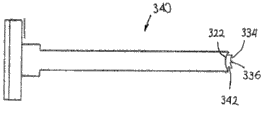
Figure 17 is the side view that inserts instrument according to the implant of one embodiment of the invention.
Figure 18 is the side view of implant insertion instrument according to an alternative embodiment of the present invention.
Figure 19 is the side view that inserts instrument according to the implant of another alternate embodiment of the present invention.
Figure 20 is the side view according to the implant countersunk localizer of one embodiment of the invention.
Figure 21 is the top view of surface dressing device that inserts the far-end adjacent positioned of instrument with implant.
Figure 22 is the perspective view that inserts the surface dressing device of the extension engagement on the far-end of instrument with implant.
Figure 23 is the perspective view that inserts the delivery cannula in the guide cannula.
Figure 24 is the perspective view that the implant that is in initial position is inserted instrument, wherein the surface dressing device be positioned at the inside of delivery cannula and wherein delivery cannula be positioned at the inside of guide cannula.
Figure 25 is the perspective view that is in the implantation insertion instrument of on position, and wherein the surface dressing device partly extends beyond the far-end of delivery cannula.
Figure 26 is the perspective view that is in the implant insertion instrument of partially retracted position, and wherein the surface dressing device moves and exceeds delivery cannula in order to the surface dressing device is implanted in the facet joint.
Figure 27 is for recall the side view that implant is inserted the lobule traction apparatus instrument of instrument from delivery cannula.
Figure 28 is the perspective view that inserts the guiding probe assembly in the facet joint, and guide cannula is to insert at the guiding probe assembly.
Figure 29 is the sectional view that has inserted a surface dressing device in the facet joint.
The specific embodiment
According to principle of the present invention and be applicable to that the embodiment of implant system 40 for the treatment of patient's facet joint is illustrated among Fig. 2.Implant system 40 can comprise upper surface trimming device 42 and lower surface trimming device 44.
As shown in Figure 2, upper surface trimming device 42 can be positioned at the top of lower surface trimming device 44, so that when upper surface trimming device 42 and lower surface trimming device 44 were directed in implantation process, upper surface trimming device 42 was directed in the opposite direction with inner surface dressing device 44.Details about surface dressing device 42,44 various assemblies provide hereinafter.
In certain embodiments, surface dressing device 42,44 can be similar each other basically, wherein upper surface trimming device 42 and last facet joint articular surface (for example superior articular surface 26 of Figure 1B) arranged adjacent, and lower surface trimming device 44 and following facet joint articular surface (for example inferior articular surface 28 of Figure 1B) arranged adjacent.
Though and do not require that in some embodiments, surface dressing device 42,44 can be similar each other basically.Therefore, the following description to upper surface trimming device 42 is equally applicable to lower surface trimming device 44.
Specifically referring to figs. 2 and 3, substrate net 50 defines the periphery 58 of surface dressing body 46.In certain embodiments, periphery 58 can have substantially circular shape, and it meets the shape of the facet joint that the surface dressing body will implant substantially.In other embodiments, girth can have ovum shape shape (with respect to end face view or bottom view).Surface dressing device 44 can form other shape, and the example comprises square, rectangle, hexagon and shaped form.
The overall dimension of surface dressing body 46 or footprint are defined by periphery 58 and can change according to the size of the facet joint for the treatment of, but less relatively usually, especially with conventional facet joint prosthesis and/or when adding cap device and comparing.As mentioned above, surface dressing body 46 should be enough contacts between the bone in the facet joint preventing greatly.
In certain embodiments, the diameter of surface dressing body 46 can the scope between about 3 millimeters and about 15 millimeters in.In other embodiments, the diameter of surface dressing body can the scope between about 5 millimeters and about 10 millimeters in.
Can provide the facet joint therapy system of the present invention with two or more different upper surface trimming devices 42 (different lower surface trimming device 44 with two or more) to the treatment clinicist, described surface dressing device has the different surface dressing body 46 of size separately.
The example of the size of surface dressing body comprises about 5 millimeters, about 8 millimeters, about 10 millimeters and about 12 millimeters.The treatment clinicist can select the optimal implantation of size surface dressing device based on the assessment of the facet joint that desire is treated.
Though wishing surface dressing body 46 enough contacts between the bone in the facet joint preventing greatly, but surface dressing body 46 should be excessive and cause surface dressing body 46 to extend beyond facet joint, because this condition may cause the damage to the adjacent tissue of the facet joint implanted with surface dressing body 46.
For the reason that hereinafter more elaborates, surface dressing body 46 can and have one or more controls preferably to insert the structure of orientation and/or direction.For example, surface dressing body 46 can insert in the facet joint with specific orientation easilier and also remain in the facet joint with specific orientation subsequently.
With respect to the configuration among Fig. 2 and Fig. 3, periphery 58 can be described as and defines leading edge or far-end 70, hangover end or near-end 72 and opposition side 74,76 substantially.During the insertion program, the orientation of surface dressing body 46 can be hangover end 72 subsequently so that leading edge 70 inserts in the facet joint at first.
The tusk 52 of the structure of consistent with these statements except having (and therefore consistent with hereinafter described expection direction of insertion and orientation), hangover end 72 can also form or define engaging structure 80, as shown in Figure 2, expectation and the interaction insertion instrument that independently provides, the more detailed argumentation hereinafter of described insertion instrument are provided for it.
In certain embodiments, engaging structure 80 is the holes that comprise at least two porose area 81a, 81b.The first porose area 81a can intersect with the edge of periphery 58 or approaching hangover end 72.The second porose area 81b and the first porose area 81a are communicated with and are oriented in the opposite side of the first porose area 81a and periphery 58.
The width that the first porose area 81a has can be less than the width of the second porose area 81b.The shape of engaging structure 80 provides partially enclosed hole to insert being connected of instrument to promote surface dressing body 46 during insertion with implant thus.
The power that surface dressing body 46 separates with implant insertion instrument should be separated so that can just surface dressing body 46 and implant can not inserted instrument 312 under being not intended to enough greatly.In certain embodiments, release surface trimming body 46 is at least 1 newton with the power of implant insertion instrument 312.In other embodiments, release surface trimming body 46 and implant are inserted the power of instrument 312 between about 1 newton and about 10 newton.In other embodiments, separating force is about 5 newton.
Separating force can be subjected to the width dimensions of the first porose area 81a and the second porose area 81b and the differentia influence of extension width.Separating force is influenced by other factors also can, inserts the rigidity of the extension on the instrument 312 such as surface dressing body 46 and implant.For example, if surface dressing body 46 or extend with flexible material and make, can specific surface trimming body 46 or extend be that separating force with under the situation of the material manufacture of relative stiffness is low to separating force so.
Engaging structure 80 can form in by the other parts of molded formation surface dressing body 46.Perhaps, engaging structure 80 can be such as forming by stamping out the zone of defining the first porose area 81a and the second porose area 81b after forming surface dressing body 46.
Might use in the process of surface dressing device 46 being inserted facet joint, making surface dressing device 46 and implant insert instrument 312 and keep other technology of engagement.A kind of example of described substituting interconnection technique is to connect surface dressing device 46 with fragility to insert instrument 312 with implant.When power during greater than threshold force, fragility connects to disconnect and allows to remove implant thus and insert instrument 312, simultaneously surface dressing body 46 is stayed in the facet joint.In certain embodiments, be at least 1 newton for the power that disconnects the fragility connection.In other embodiments, be used for disconnecting the power of fragility connection between about 1 newton and about 10 newton.In other embodiments, separating force is about 5 newton.
In certain embodiments, substrate net 50 have in some constructions relative homogeneous thickness (for example nominal thickness be changed to+/-0.05mm), as shown in Figure 3.Substrate net 50 makes formed composition surface 54 level and smooth relatively.This smoothness attribute is at least part of to be become with surface dressing body 46 used materials, as mentioned below.
In other embodiments, the composition surface 54 of substrate net 50 can scribble the independent stratum that friction (for example than low-friction coefficient) and wearing character are enhanced.A kind of example with described material of low-friction coefficient is polytetrafluoroethylene (PTFE), and it can obtain by title TEFLON.
A plurality of tusks 52 are outstanding from second first type surface 56 of substrate net 50.These tusks 52 can have various ways.In some embodiments, tusk 52 is arranged in and forms or define discrete district or tusk group, such as the first, second, and third tusk group 90,92,94 that identifies substantially among Fig. 2.
The first tusk group 90 can be positioned at the center, extends between leading edge and hangover end 70,72 along substrate net 50.Indivedual tusks of the first tusk group 90 can be identical substantially.More particularly, guide face 98 and trailing face 100 before each tusk can comprise, it intersects from 56 extensions of second first type surface and most advanced and sophisticated 102.Before the orientation of guide face 98 can be more near leading edge 70 (comparing with trailing face 100), and the orientation of trailing face 100 can more approaching hangover end 72.
Because these statements, tusk can be configured to define direction of insertion, and wherein the angle α that is formed with respect to second first type surface 56 by preceding guide face 98 is less than the angle β that is formed with respect to second first type surface 56 by trailing face 100.
In these configurations, preceding guide face 98 is compared with respect to the slope of hangover end 72 with trailing face 100 with respect to the slope of leading edge 70 can be comparatively mild, so that tusk 96a meshes absolute construction more significantly with comparing with preceding guide face 98 along trailing face 100 on trailing face 100, such as facet joint upper side (not shown).
In some configurations, the angle α that is defined by preceding guide face 98 can be in 20 ° of-60 ° of scopes, and are about 90 ° by the angle β that trailing face 100 defines.Suitable angle can be subjected to multiple factor affecting, such as in order to make the material of surface dressing body 46.In any case, and return Fig. 2, all the other tusks of the first tusk group 90 can be as shown at two row or more aligned with each other in the multirow.
The second tusk group 92 and the 3rd tusk group 94 can form on opposition side 74,76 or along opposition side 74,76 respectively, as shown in Figure 2.With regard to this point, though the second and the 3rd tusk group 92, indivedual tusks of 94 can have above-mentioned asymmetrical relationship with respect to above-mentioned tusk, with the second and the 3rd tusk group 92, exterior face 104 that each tusk of 94 is relevant establish extend with respect to second first type surface 56 near 90 ° angle.
Utilize this a kind of acceptable structure, the second and the 3rd tusk group 92,94 obviously stops inserts rear surface trimming body 46 with respect to the displacement of corresponding facet joint face from a side to opposite side.For example, the second tusk group 92 can stop surface dressing body 46 to left dislocation, and the 3rd tusk group 94 can stop displacement to the right.
In certain embodiments, each tusk in a plurality of tusks 52 can have identical or near identical height the extension of second first type surface 56 (or from), as shown in Figure 3.In other embodiments, the toothed height comparable second of the first tusk group 90 and the 3rd tusk group 92,94 dentation object height, and capable of being combined to define the cone height of surface dressing body 46 from leading edge 70 to hangover end 72.
In other words and with respect to embodiment shown in first first type surface, 54 planes, the height of leading tusk 96a is greater than the height of hangover tusk 96b.For example, the hypothesis plane P is made up to define in relevant with the tusk of the first tusk group 90 tip 102.In some embodiments, plane P is with respect to the plane out of plumb of first first type surface 54, thereby and 54 combinations of first first type surface with the angle Δ of confining spectrum between about 1 ° and about 5 °.
In other embodiments, also expect other angle, wherein tusk 52 has substantially similar height.In certain embodiments, the highest tusk 96a can be arranged on the leading edge 70, and its final position is opposite with the insertion point in the facet joint.Therefore, leading tusk 96a can set up the engagement with the more rigidity of corresponding facet joint face, obviously stops displacement in the final back of inserting thus.
In some constructions, the general thickness of surface dressing body 46 but is also expected other size between about 0.25 millimeter and about 4 millimeters.As mentioned, relevant with the surface dressing body 46 that select to be used for is inserted specific facet joint by treatment clinicist general thickness T can be along with changing with inserting other program of being correlated with.
For example, do not remove before inserting under the situation about under any situation that appears tissue surface dressing body 46 being inserted in the facet joints, general thickness T can be between about 0.5 millimeter and about 2.5 millimeters.If the insertion program requires at first to remove cartilage (or other tissue) from facet joint, can insert the surface dressing body 46 of relatively large formula so, so the general thickness T of surface dressing body 46 can be between about 0.5 millimeter and about 3 millimeters.
In some constructions, surface dressing device 42,44 can be formed by the plastics of implantable level, but also can use other material, such as metal.For example, surface dressing device 42,44 can be made by the plastics of polyether-ketone (PEK) family, and described plastics have and are suitable for inserting in the facet joint and the intensity that works for a long time in facet joint, wearing and tearing, flexibility and biocompatibility characteristic.
Found that polyether-ether-ketone (PEEK) not only provides suitable shape attribute hereinafter described, but also long-term mechanical strength and mar proof are provided.Can incorporate other material into, such as showing the not material of saturating radiation characteristic.For example, surface dressing device 42,44 can be formed by the PEK compositions that is loaded with radiopaque mineral (for example barium).
Can also observe by one or more radiopaque indicia band (for example platinum indicia band).Indicia band can be embedded in the surface dressing device 42,44.For example, radiopaque shaft can be inserted in the hole that forms in the surface dressing device 42,44, as shown in Figure 5.Perhaps, can around surface dressing device 42,44 periphery, insert radiopaque material.
Each surface dressing device 42,44 selected materials, shape and size relevant with surface dressing body 46 have surface dressing body 46 or produce the suitable shape characteristic that is enough to allow surface dressing body 46 " coupling " relevant many planes concave surface with natural facet joint articular surface anatomical structure.
Under the situation of the surface dressing device 42 of Fig. 2,44 embodiments, surface dressing body 46 forms respective surfaces trimming devices 42,44 integral body.Hereinafter in described other embodiment, can include one or more add-on assembles in surface dressing body 46, so that be specially adapted to surface dressing body 46 about the following explanation of conformal performance, but can also be equally applicable to surface dressing device 42,44 as a whole.
In general, " conformal performance " can be inversely proportional to the bending stiffness of surface dressing body 46 during inserting, and can be heated to body temperature with surface dressing body 46 and increase and make its creep.According to clinical point, " conformal performance " of surface dressing body 46 requires surface dressing body 46 to meet the C shape in joint or the radius of curvature of J-shaped part (such as the spill superior articular surface 26 of Figure 1B or the convex inferior articular surface 28 of Figure 1B).
As mentioned, the minimum profile curvature radius of people's facet joint is 20 millimeters levels on transverse plane, and its lower limit (10) is 7 millimeters levels.Radius of curvature will become with spinal column aspect and patient's concrete anatomical structure and the disease patient's condition.Insert the preparation of before the surface dressing device 42,44 facet joint being made and also can change radius of curvature.
Because above-mentioned understanding, surface dressing body 46 peculiar conformal performances are enough to make that surface dressing body 46 easily becomes the insertion state (not shown by the relatively flat state-transition shown in Fig. 2, but for example reflection to some extent in Figure 30), mate or simulate the naturally occurring shape (for example radius of curvature of sweep) of 46 fastening facet joint faces thereon of surface dressing body basically at the state of insertion lower surface trimming body 46.With regard to this point, facet joint 20 (Figure 1B) stands or experiences the various loads of the interface zone realization compression stress between superior articular surface and inferior articular surface 26,28 (Figure 1B).
These physiology power on the facet joint 20 will change with activity, attitude, body burden and muscular force, and when standing, tend to body burden about 7% and about 14% between.Yet when being in position prostrate, flexing a little during surgical operation/implantation, it only is zero that these loads may be low to moderate.Inherent power will produce along with inserting surface dressing device 42,44 (with therefore corresponding surface dressing body 46) and joint capsule 32 (Figure 1B) tensioning.To the compression of lower floor's cartilage and subchondral bone bone, flexing or lamina of vertebral arch is tight may produce a little, and with storing apparatus 42, some thickness of 44.Yet, with the separation/rear portion translation of facet on the needs major part with storing apparatus 42, all thickness of 44.
Separate because of the joint capsule tensioning at last facet/produce after the translation of rear portion perpendicular to articular surface 26,28 and compression load on whole articular surface 26,28.The conformal performance matter of surface dressing body 46 makes in the presence of these typical compression stresses, surface dressing body 46 will be become the insertion state by the state-transition of relatively flat, under described insertion state, surface dressing body 46 is the geometry on 46 fastening facet joint surfaces thereon of match surface trimming body basically.
For example, surface dressing body 46 is with the macroshape/profile of bending with the natural joint face that meets surface dressing body 46 and be applied thereon, but the micro-variations of the natural joint face that the deviation due to the little space (width is usually between about 0.05 millimeter and about 0.5 millimeter) during may not meeting reason cartilage defects, bone splits or preparing the joint causes.
This process will by the end of the hypothesis concave regions of a facet joint surface (for example the upper joint surface 26) with twisting of joints facet (for example the hypozygal surface 28) mutually on the compression stress that applies of the center on respective male surface surface dressing body 46 produced cause that thus strain takes place when making surface dressing body 46 meet the bending moment of natural anatomic structure.
As used in this description, under normal physiological power (for example suppose clean rear portion shear translation 1 millimeter time between about 180 Newton/millimeter of each sections and about 450 Newton/millimeter), meet the minimum profile curvature radius of the facet joint of being grown up and the articular surface deviation that is not applied thereon with the surface dressing body is defined as many plain bendings part that " suitable shape " reach " mating basically " facet joint greater than 1 millimeter surface dressing body.
Perhaps, according to the present invention, size is suitable for being placed in adult's facet joint and shows that the surface dressing body that the suitable shape factor (describing hereinafter) is not more than 100 newton also is defined as many plain bendings part that " suitable shape " reach " mating basically " facet joint.In some embodiments, surface dressing body of the present invention shows that the suitable shape factor is not more than 50 newton, and is not more than 25 newton in other embodiments.
Unexpected discovery the, the surface dressing body 46 (and therefore any one in the surface dressing device 42,44 of the embodiment of Fig. 2) that forms and have above-mentioned footprint size and gauge with PEEK realize conformal performance feature, the long-term mar proof of expectation and insert after facet joint stable.
Another embodiment of surface dressing body 46 is in shown in Fig. 4-6.Except hereinafter described, surface dressing body 46 can have and the similar overall shape of surface dressing body shown in Fig. 2-3 and similar tusk kenel.
Although might in the process for the manufacture of surface dressing body 46, incorporate radiopaque labelling 82 into, also might after manufacturing, radiopaque labelling 82 be inserted in the surface dressing body 46.
A kind of being included in the surface dressing body 46 for the described suitable technology that radiopaque labelling 82 is inserted the surface dressing device forms the hole.In certain embodiments, the hole can use drill bit to form.
In certain embodiments, radiopaque labelling 82 can be positioned over the surface dressing body 46 from its hangover end 72 near surface dressing body 46 center lines.Use this configuration to obtain having symmetric surface dressing body 46 to help the position based on the medical imaging assessment surface dressing body 46 of radiopaque labelling 82.
With radiopaque labelling 82 place surface dressing body 46 should be relatively accurately so that radiopaque labelling 82 can not extend through a surface of surface dressing body 46.This situation takes place may cause surface dressing body 46 degradation maybe may cause in the facet joint tissue injury adjacent with surface dressing body 46.
For guaranteeing that radiopaque labelling 82 can not extend through the upper surface of surface dressing body 46, can with radiopaque labelling 82 adjacent areas in zones of add-on material 84 is set, as shown in Figures 4 and 5.The radiopaque labelling of settling in zones of add-on material 84 82 can be about equally in upper surface and the distance between the lower surface of surface dressing body.
Can extend microscler tab 86 from the hangover end 72 of surface dressing body 46.Microscler tab 86 can be used in the manufacture process and then namely disconnects with the other parts of surface dressing body 46 after manufacturing is finished.Perhaps, opposite with implant system as herein described, microscler tab 86 can use in conjunction with surface dressing body 46 is inserted in the facet joint.In said case, can a line of weakness be set in microscler tab 84 and the place that surface dressing body 46 intersects.
Another embodiment of surface dressing body 46 is in shown in Fig. 7-9.Except hereinafter described, surface dressing body 46 can have and the similar overall shape of surface dressing body shown in Fig. 2-3 and similar tusk kenel.
Can extend microscler tab 86 from the hangover end 72 of surface dressing body 46.The 26S Proteasome Structure and Function of microscler tab 86 can be similar to the 26S Proteasome Structure and Function of microscler tab 86 in the embodiment of the surface dressing body 46 shown in Fig. 4-6.
An importance of accurately sending surface dressing body 46 is accurate facet joints of location expectation not only, but also with respect to the accurate seating surface trimming of facet joint body delivery system, accurately inserts in the facet joints to allow surface dressing body 46.
In certain embodiments, the guiding probe assembly 200 as shown in Figure 10-11 can be used for the zone that location facet joint desire is inserted surface dressing device 46 at the beginning.Guiding probe assembly 200 can comprise guiding probe shaft 202 and from the guiding probe tip 204 of remote extension of guiding probe shaft 202.
The profile that guiding probe shaft 202 can have substantial rectangular is as shown in Figure 10 and Figure 11.The guiding probe shaft 202 that formation has a substantial rectangular profile makes after guiding probe assembly 200 is positioned to that guiding probe tip 204 is at least part of and is arranged in facet joint, guide cannula 260 can be slided at guiding probe assembly 200, as hereinafter more detailed argumentation.When comparing with the implant system that does not utilize this insertion process, this process reduces with implant surface rebuilds the relevant time of body 46.
For make the incision size minimum that forms in patient's body, guiding probe shaft 202 can form width and highly be substantially equal to width and the height of surface dressing body 46.
In certain embodiments, the width of guiding probe shaft 202 is between about 5 millimeters and about 20 millimeters.In other embodiments, the width of guiding probe shaft 202 is about 12 millimeters.
In certain embodiments, the thickness of guiding probe shaft 202 is between about 0.20 millimeter and about 10 millimeters.In other embodiments, the thickness of guiding probe shaft 202 is about 2 millimeters.
Guiding probe shaft 202 forms length and makes when the far-end that guides probe shaft 202 is adjacent with facet joint, and the near-end of guiding probe shaft 202 can be positioned the outside of patient body.This disposing is beneficial to the surgeon that uses guiding probe assembly 200 or other personnel with respect to the accurate orientation direction probe assembly 200 of facet joint.
In certain embodiments, the length of guiding probe shaft 202 is between about 10 centimetres and about 30 centimetres.In other embodiments, the length of guiding probe shaft 202 is about 23 centimetres.
The far-end of guiding probe shaft 202 can comprise tapered zone 206, as shown in Figure 10-11, so that the transformation between guiding probe shaft 202 and the guiding probe tip 204 to be provided.The length of tapered zone 206 can be depending on multiple factor, such as the width of guiding probe shaft 202 and guiding probe tip 204 and the difference of height.
Guiding probe shaft 202 can make to be conducive to use guiding probe shaft 202 to use guiding probe tip 204 location facet joints by the material of relative stiffness.In certain embodiments, guiding probe shaft 202 can be made by rustless steel.In other embodiments, might make guiding probe shaft 202 by nonmetallic materials such as plastics.
Important criteria is to guide probe shaft 202 to be made by biocompatible materials.Be used further to a plurality of surgical procedure if wish guiding probe shaft 202, guide probe shaft 202 should be able to bear such as the repetition sterilization process by using pressure cooker to carry out so.
Guiding probe tip 204 is operably connected to the near-end of guiding probe shaft 202.In certain embodiments, guiding probe shaft 202 forms porose 210 in its far-end.This hole 210 is suitable for admitting the part of guiding probe tip 204.
The length of near-end that extends beyond guiding probe shaft 202 of the comparable guiding probe tip 204 of the length that extends to the part in the hole 210 of guiding probe tip 204 is long, to strengthen the ability that guides probe tip 204 when the desired locations of attempting to locate in the facet joint.
Formation and the guiding probe tip that separates of other parts 204 of guiding probe assembly 200 make that size, shape and the position of the facet joint that guiding probe tip 202 with different in width and/or length can insert according to the surface dressing device are used.
The thickness of guiding probe tip 204 and width can be all less than the thickness and the width that guide probe shaft 202.In certain embodiments, the width of guiding probe tip 104 is between about 5 millimeters and about 20 millimeters.In other embodiments, the width of guiding probe tip 104 can be about 9 millimeters.
In certain embodiments, the thickness of guiding probe tip 204 can be between about 0.10 millimeter and about 0.50 millimeter.In other embodiments, the thickness of guiding probe tip 204 can be about 0.20 millimeter.
It is not sharp-pointed that guiding probe tip 204 can form near-end.Be formed on guiding probe tip 204 that near-end has this configuration make guiding probe tips 204 will damage in the facet joint or facet joint on every side tissue or to cause the probability of other negative effect to be down to described tissue minimum.
In certain embodiments, the near-end of guiding probe tip 204 might be sharp keen so that when attempting near facet joint, and guiding probe tip 204 can be used for cutting and organizing.
Guiding probe tip 204 can be made by firm but flexible material.Forming guiding probe tip 204 by bendable material strengthens when the implant surface trimming body 46 and will guide probe tip 204 at least part of abilities that are placed in the facet joint as initial step.
In certain embodiments, guiding probe tip 204 is made such as rustless steel by metal material.Also might use conception of the present invention by nonmetallic materials manufacturing guiding probe tip 204.
An important criteria is that selecting for the manufacture of the material that guides probe tip 204 is that described material has biocompatibility.Be used further to a plurality of surgical procedure if wish guiding probe tip 204, guide probe tip 204 should be able to bear such as the repetition sterilization process by using pressure cooker to carry out so.
Guiding probe tip 204 can use at least one clamp device 212 to be attached to guiding probe shaft 202.In certain embodiments, use at least two clamp devices 212 will guide probe tip 204 to be attached to guiding probe shaft 202.
As an alternative arrangements of guiding probe assembly 200 configurations shown in Figure 10-12, can be in conjunction with the alternative arrangements of conception utilization guiding probe assembly 200 of the present invention.A kind of described alternative arrangements of guiding probe assembly is illustrated among Figure 13 with 240.Guiding probe assembly 240 comprises microscler principal part 242 and is attached to the shank 244 of the near-end of principal part 242.
Principal part 242 can have with the guiding probe shaft 202 shown in Figure 10-11 and similarly disposes.Though Figure 13 illustrates principal part 242 and do not have independent tip portion, conception that might this embodiment of transformation to be to forgive independent tip portion, makes tip portion can have the physical features different with the principal part 242 that extends tip portion.Even independent tip portion is not set, the near-end of principal part 242 also can dwindle gradually and be beneficial to guiding probe assembly 240 is guided to desired locations in the facet joint.
Shank 244 strengthens the ability that grips guiding probe assembly 240 in the insertion process.In certain embodiments, the width of shank 244 can be greater than the width of principal part 242.The thickness of shank 244 also can be greater than the thickness of principal part 242.
Can use guiding probe assembly 240 in conjunction with guiding probe assembly 200.In this configuration, principal part 242 can with guiding probe assembly 200 arranged adjacent.When being used for this configuration, principal part 242 and guiding probe assembly 200 can be thinner than the configuration of separately using, and make principal part 242 and guiding probe assembly 200 can all be installed in guide cannula 260 inside.
This configuration can utilize shank 244 will guide the far-end of probe assembly 200 to guide in the interior position of facet joint.After this, can extract guiding probe assembly 240 out.Then, guide cannula 260 can be placed on the guiding probe assembly 200.
Delivery system can comprise guide cannula 260, as shown in Figure 14 and Figure 15.Guide cannula 260 has the inner passage 262 from proximal extension to its far-end.In certain embodiments, passage 262 can have the configuration of general rectangular.
The width of passage 262 is less than the width of delivery cannula 280.In certain embodiments, the width of passage 262 can be between about 3 millimeters and about 15 millimeters.In other embodiments, the width of passage 262 is between about 5 millimeters and about 10 millimeters.
The height of passage 262 is less than the height of delivery cannula 280.In certain embodiments, the height of passage 262 can be between about 0.50 millimeter and about 5 millimeters.In other embodiments, the height of passage 262 is about 2 millimeters.
For being conducive to respect to the accurate orientation direction intubate 260 of facet joint, the near-end of guide cannula 260 can have concave surface 266.Concave surface 266 can at least part of admittance facet joint convex surface, prevent from guide cannula 260 thus with respect to the facet joint shifted laterally and strengthen thus the surface dressing device is accurately inserted ability in the facet joint.
Be the ability of the different assemblies that strengthen the use system, second shut-down mechanism 272 can be the spaced relationship location with respect to first shut-down mechanism 270.In certain embodiments, the spacing between first shut-down mechanism 270 and second shut-down mechanism 272 is between about 1 centimetre and about 5 centimetres.
The width of passage 282 inserts the width of the principal part 312 of instrument 310 less than implant.In certain embodiments, the width of passage 282 can be between about 3 millimeters and about 15 millimeters.In other embodiments, the width of passage 282 is between about 5 millimeters and about 10 millimeters.
The height of passage 282 inserts the height of the principal part 312 of instrument 310 less than implant.In certain embodiments, the height of passage 282 can be between about 0.5 millimeter and about 5 millimeters.In other embodiments, the height of passage 282 is about 2 millimeters.
During near the near-end of delivery cannula 280, can remove the side of passage 282, so that the upper side of delivery cannula 280 and bottom surfaces define a pair of arm.When implant was inserted in the instrument 310 insertion delivery cannula 280, the width of at least a portion of shoulder 320 can be greater than the width of delivery cannula 280, as shown in Figure 24.This configuration limits implant thus and inserts instrument 310 and can insert distance in the delivery cannula 280.
The width of the lobule 284 roughly width with surface dressing body 46 is identical.Far-end less than 284 can be crooked.Thus in lobule moves at least partially in the position in the facet joint to provide when being suitable in the facet joint admitting the opening of surface dressing body 46, the curved distal end of lobule 284 makes is down to minimum to the damage of the superior articular surface of facet joint and inferior articular surface.
Separating lobule 284 required power should be enough big so that lobule 284 remains on closed configuration.Yet described power should excessively not cause surface dressing body 46 to be difficult to advancing or causing lobule 46 injured surface trimming body 46 when surface dressing body 46 passes through between the lobule 284 between the lobule 284 in implantation process.
Near the near-end of delivery cannula 280, shut-down mechanism 286 can extend from least one outer surface of delivery cannula 280.Shut-down mechanism 286 can be the orientation height district of the axle of cross-section delivery cannula 280 substantially.
In certain embodiments, shut-down mechanism 286 can comprise two height districts of installing with isolated configuration, as shown in Figure 16.Two high districts are defined in the passage 288 that extends thus therebetween.Passage 288 is suitable for admitting the part of lobule traction apparatus instrument 360, and described lobule traction apparatus instrument 360 can be used for extracting out delivery cannula 280 from guide cannula 260.
First shut-down mechanism 270 on the shut-down mechanism 286 engagement guide cannula 260.Shut-down mechanism 286 limits delivery cannula 280 thus can insert distance in the guide cannula 260.
One embodiment of the invention can also comprise implant insertion instrument 310, as shown in Figure 17.Implant is inserted the shank 314 that instrument 310 can comprise principal part 312 and be attached to the near-end of principal part 312.
The width of principal part 312 and highly can be slightly less than delivery cannula 280 width and the height.This configuration makes principal part 312 can be placed in delivery cannula 280 inside in the process of inserting surface dressing body 46 and slides with respect to delivery cannula 280.
In certain embodiments, the width of principal part 312 can be between about 3 millimeters and about 15 millimeters.In other embodiments, the width of principal part 312 can be between about 1 millimeter and about 5 millimeters.
In certain embodiments, the height of principal part 312 can be between about 0.5 millimeter and about 5 millimeters.In other embodiments, the width of principal part 312 is about 2 millimeters.
At intersection point place approaching and shank 314, principal part 312 can comprise the shoulder 320 that extends out from its at least one side.Shoulder 320 can be used for limiting implant by second shut-down mechanism 272 on the engagement guide cannula 260 and insert the distance that instrument 310 can insert delivery cannula.
The orientation of shank 314 can be substantially perpendicular to principal part 312.Shank 314 provides thus and can be used for gripping the enlarged surface that implant is inserted instrument 310 and is conducive to handle implant insertion instrument 310 thus.In certain embodiments, the length of shank 314 can be between about 5 centimetres and about 15 centimetres.
The far-end 322 of principal part 312 can comprise and bends at least part of concave surface 323 that meets the surface of surface dressing body 46.Concave surface strengthens thus makes surface dressing body 46 insert the ability that instrument 310 remains in desired locations with respect to implant.
Make surface dressing body 46 insert the ability that instrument 310 remains in desired locations with respect to implant for further strengthening, can extend from far-end 322 and extend 324.Extend 324 and be suitable for meshing the engaging structure 80 that is arranged in the surface dressing body 46.
Extend 324 can have with engaging structure 80 similar but be slightly smaller than the shape of engaging structure 80.Specifically, extend 324 and can comprise the first extension area 326a and the second extension area 326b.
The width that the first extension area 326a has is less than the width of the first porose area 81a.The width that the second extension area 326b has is greater than the width of the first porose area 81a and less than the width of the second porose area 81b.This configuration makes that extending 324 can remain in the engaging structure 80 to prevent that surface dressing body 46 and implant insertion instrument 310 from separating.More details about engaging structure 80 and the relative size of extension 324 are above being discussed.
Figure 21 and Figure 22 illustrate the relation between surface dressing body 46 and the implant insertion instrument 310.In Figure 21, surface dressing body 46 with plant
Go into thing and insert the adjacent but spaced apart arrangement of instrument 310.In Figure 22, surface dressing body 46 inserts instrument 310 engagements with implant, makes that extending 324 extends into and mesh described engaging structure 80.The shape of engaging structure 80 can be roughly identical with the shape of extending 324.
Because surface dressing body 46 accurately being placed in successfully to treat among the patient and playing an important role in facet joint is configured to insert second shut-down mechanism 272 on shank 314 engagement guide cannula 260 in delivery cannula 280 and the guide cannula 260 so implant is inserted instrument 310.This configuration prevents that surface dressing body 46 is not intended to excessively insert.
In some cases, the shape of the facet joint of implanting according to surface dressing body 46 may wish surface dressing body 46 is inserted different distance in facet joint.For being conducive to that surface dressing body 46 is accurately inserted desired depth, embodiment of the present invention utilize implant to insert instrument 330 and 340, as shown in Figure 18 and Figure 19.These implants are inserted instrument 330,340 the selected countersunk of surface dressing body 46 in facet joint are provided.
Be different from feature hereinafter described, implant is inserted instrument 330,340 and is had and insert instrument 310 with the implant shown in Figure 17 and similarly dispose.Implant among Figure 18 is inserted instrument 330 and is comprised that the countersunk that comes out from its remote extension extends 332.Countersunk extension 332 can have the similar female end of the curvature surface 334 of curvature and surface dressing body 46.
Similar with the embodiment among Figure 17, in countersunk extension 332 extension 336 is set and inserts instrument 330 to help surface dressing implant 46 to be attached to implant.
End surfaces 334 is spaced apart with concave surface 322.In certain embodiments, the distance between the end surfaces can be between about 1 millimeter and about 10 millimeters.In other embodiments, the distance between the end surfaces can be about 3 millimeters.
Countersunk extends 332 width and highly can be slightly less than width and the height of principal part 312.This configuration make countersunk extend 332 with the interior tissue of facet joint between the probability that contacts be down to minimum because described contact may cause undesirable side effect.
It is similar with the implant insertion instrument 330 among Figure 18 that implant among Figure 19 is inserted instrument 340, and the exception part is that countersunk extension 342 is long slightly.In certain embodiments, the length of countersunk extension 342 can be about 5 millimeters.
Also might utilize countersunk localizer 350 in conjunction with the desired locations that surface dressing body 46 is positioned in the facet joint, as shown in Figure 20.It is similar that countersunk localizer 350 and the implant shown in Figure 18 are inserted instrument 330, and the exception part is that countersunk localizer 350 does not comprise the extension of coming out from its remote extension.
Can after having inserted in the facet joint, surface dressing body 46 recognize that thus surface dressing body 46 utilizes countersunk localizer 350 when inserting enough deeply in facet joint.After from delivery cannula 280, removing implant insertion instrument 310, countersunk localizer 350 is inserted in the delivery cannula 280.
Be similar to implant and insert the shank 314 of the distance that restriction implant insertion instrument 310 can insert on the instrument 310 in delivery cannula 280, the distance that shank 352 restriction countersunk localizers 350 on the countersunk localizer 350 can insert in delivery cannula 280 is so that surface dressing body 46 can accurately be located in facet joint.
When operation, need the facet joint place of implant surface trimming body 46 to cut in the approaching of patient.Guiding probe assembly 200 is inserted in patient's body so that guiding probe tip 204 can be used for identifying the joint line in the facet joint.
Then, guide cannula 260 is slided at guiding probe assembly 200, as shown in Figure 28, adjacent until far-end and the facet joint of guide cannula 260.Guiding probe assembly 200 makes that thus guide cannula 260 can be accurately and be placed in position for implantation process rapidly.
Then will guide probe assembly 200 to extract out from guide cannula 260, careful operation is so that guide cannula 260 remains on the fixed position with respect to facet joint., delivery cannula 280 inserted in guide cannula 260 thereafter, rib 281 engagements first shut-down mechanism 270 on delivery cannula 280, as shown in Figure 23.First shut-down mechanism 270 limits delivery cannula 280 thus can insert distance in the guide cannula 260.
In this configuration, lobule 284 is from the remote extension of guide cannula 260.When the far-end of guide cannula 260 was adjacent with facet joint, lobule 284 extended into facet joint to cause being formed on the zone that can insert surface dressing body 46 in the subsequent operation.
Then, the far-end adjacent positioned that surface dressing body 46 and implant are inserted instrument 310 extends into engaging structure 80 in order to extend 324, as shown in figure 22.Subsequently implant is inserted the near-end that instrument 310 inserts delivery cannula 280.
When implant insertion instrument 310 almost completely inserted in the delivery cannula 280, surface dressing body 46 was hidden in the delivery cannula 280, as shown in Figure 24.
In some embodiments, may need to use lobule dilator (not shown) lobule 284 to be kept be in and separate configuration, so that surface dressing body 46 can be positioned between the lobule 284.Use the lobule dilator if desired, can change loading process a little so, so that surface dressing body 46 is attached to implant insertion instrument 310 and then implant is inserted instrument 310 and inserted in the delivery cannula 280.
Continue to insert implant insertion instrument 310 and begin to come out from the remote extension of delivery cannula 280 until surface dressing body 46, as shown in Figure 24.At this moment, shoulder 320 engagements second shut-down mechanism 272 inserts the distance that instrument 310 can insert with the restriction implant in delivery cannula 280.As mentioned above, but lobule 284 deflections to be provided for that surface dressing body 46 is inserted space in the facet joints.
Then, delivery cannula 280 is pushed away facet joint, as shown in Figure 26.This motion causes that lobule 284 is retracted in the delivery cannula 280.Facet joint returns to its initial position, and this causes the space that surface dressing body 46 is filled between the bone.
In some cases, may need to use lobule traction apparatus instrument 360 (shown in Figure 27) that delivery cannula 280 is pushed away facet joint.Lobule traction apparatus instrument 360 comprises the first handle section 362 and the second handle section 364 of relative to each other pivotally installing.
The first handle section, 362 engagement implants are inserted the shank 314 on the instrument 310.In certain embodiments, shank 314 can have the hole that extends through wherein and the first handle section 362 can extend through described hole to insert instrument 310 fastening lobule traction apparatus instruments 360 with respect to implant.
After this, the engagement of the end of the second handle section 364 is from the lip 366 of delivery cannula 280 near its proximal extension.The second handle section 364 pivots with respect to the first handle section 362, shown in arrow 368.This pivoting action causes that delivery cannula 280 pushed away from facet joint, makes in the lobule 284 retraction induced intubate 260.Guide cannula 260 deviates from the probability that facet joint moves by its desired locations in the implantation process to be reduced in towards facet joint in this motion.
After this, can so that surface dressing device 42,44 is stayed implant insertion instrument 310 be separated with surface dressing body 46 by be pulled away from surface dressing body 46 light and slowly, as shown in Figure 29.Implantation process is finished thus.Can before removing with the facet joint position adjacent, use the medical imaging method to assess the whether accurately implantation of surface dressing body guide cannula 260.
In aforementioned detailed description, mention accompanying drawing, described accompanying drawing forms the part of this paper, and illustrate in the mode of graphic extension in described accompanying drawing can be for implementing specific embodiments of the present invention.With regard to this point, directional terminology is to use under the situation of orientation of the described figure of reference such as " top ", " bottom ", " front portion ", " back ", " leading ", " hangover " etc.Because the assembly of embodiment can be multiple the different orientation location, so described directional terminology be never have for illustrative purposes restricted.Should be understood that under the situation that does not deviate from scope of the present invention, can utilize other embodiment and can carry out structure or the logic variation.Therefore, the aforementioned detailed description of getting does not have restrictive, sense, and scope of the present invention is to be defined by the claims of enclosing.
The feature described in disclosed feature and the above-mentioned application incorporated into by reference can be mixed and mate with suitable particular condition among expection the application.Various other modifications and variations will be apparent for those of ordinary skill in the art.
Claims (50)
1. system that is used for the treatment of patient's facet joint, wherein said facet joint comprises superior articular surface and inferior articular surface, wherein said system comprises:
Can be positioned the surface dressing device between the inferior articular surface of the superior articular surface of facet joint and facet joint; Be suitable for meshing the implant insertion instrument of described surface dressing device; And have the guide cannula that extends through inner passage wherein, wherein said guide cannula passage is suitable for admitting at least a portion of described surface dressing device and described implant to insert instrument.
2. the system as claimed in claim 1, wherein said surface dressing device comprise that first surface trimming part and second surface rebuild part.
3. the system as claimed in claim 1, wherein said surface dressing device shows the flexibility that is enough to become from the state-transition of relatively flat the insertion state, under described insertion state, described surface dressing device mates any many plain bendings part of described superior articular surface basically.
4. the system as claimed in claim 1, wherein said surface dressing device has a plurality of tusks on its at least one surface.
5. the system as claimed in claim 1, wherein said surface dressing device comprises first engaging structure, wherein said implant is inserted device and is comprised second engaging structure that can cooperate described first engaging structure, and wherein the power that cooperates the back to separate described first engaging structure and described second engaging structure is at least 1 newton.
6. system as claimed in claim 5, wherein:
Described first engaging structure comprises first porose area and second porose area, and wherein said first porose area intersects with the edge of described surface dressing device and wherein said second porose area is communicated with described first porose area; And
Described second engaging structure comprises first extension area and second extension area, and wherein said second extension area is attached to described implant and inserts device and wherein said first extension area and be attached on described second extension area and insert the device opposite position with described implant.
7. the system as claimed in claim 1, wherein said implant are inserted instrument and are further comprised:
Principal part with near-end and far-end;
Be attached to the shank near described proximal end of described principal part; With
By at least one shoulder that extends out in described principal part and the described shank, the width of wherein said shoulder is greater than the width of described principal part.
8. the system as claimed in claim 1, wherein said surface dressing device and described implant are inserted instrument and are installed slidably with respect to described guide cannula.
9. the system as claimed in claim 1, wherein said guide cannula has at least part of concave distal end surface that meets the edge of described surface dressing device.
10. the system as claimed in claim 1, and further comprise the guiding probe assembly, described guiding probe assembly comprises the guiding probe tip, and the width of wherein said guiding probe assembly is less than the height of described guide cannula width of channel and the described guiding probe assembly height less than described guide cannula passage.
11. system as claimed in claim 10, wherein said guiding probe tip is to be mounted to described guiding probe assembly removably.
12. system as claimed in claim 10, the width of wherein said guiding probe tip is less than the height of the width of described guiding probe assembly and the wherein said guiding probe tip height less than described guiding probe assembly.
13. the system as claimed in claim 1, and further comprise delivery cannula, described delivery cannula has the inner passage that extends through wherein, and wherein said delivery cannula passage is suitable for admitting at least a portion of described surface dressing device and described implant is inserted instrument and wherein said guide cannula passage is suitable for admitting described delivery cannula.
14. system as claimed in claim 13, wherein said delivery cannula comprise that a pair of lobule and the wherein said lobule of installing near its far-end is to be made by elastomeric material.
15. system as claimed in claim 13, wherein said guide cannula with respect to described delivery cannula be install slidably and wherein said surface dressing device and described implant to insert instrument be to install slidably with respect to described delivery cannula.
16. the system as claimed in claim 1, and further comprise the traction apparatus instrument, described traction apparatus instrument comprises:
Can mesh described implant and insert the first handle section of instrument; With
May be operably coupled to the second handle section of the described first handle section, the wherein said second handle section can mesh described delivery cannula.
17. system as claimed in claim 16, the wherein said first handle section pivotally are mounted to the described second handle section.
18. a system that is used for the treatment of patient's facet joint, wherein said facet joint comprises superior articular surface and inferior articular surface, and wherein said system comprises:
Be configured at least one the surface dressing device of shape in the inferior articular surface that selectivity meets the superior articular surface of facet joint and described facet joint, wherein said surface dressing device comprises first engaging structure; With
Implant with second engaging structure that can cooperate described first engaging structure is inserted device, and wherein the power that cooperates the back to separate described first engaging structure and described second engaging structure is at least 1 newton.
19. system as claimed in claim 18 wherein cooperates the back to separate the described power of described first engaging structure and described second engaging structure between about 1 newton and about 10 newton.
20. system as claimed in claim 18, wherein:
Described first engaging structure comprises first porose area and second porose area, and wherein said first porose area intersects with the edge of described surface dressing device and wherein said second porose area is communicated with described first porose area; And
Described second engaging structure comprises first extension area and second extension area, and wherein said second extension area is attached to described implant and inserts device and wherein said first extension area and be attached on described second extension area and insert the device opposite position with described implant.
21. system as claimed in claim 20, the width of wherein said first porose area is less than the described second porose area width, the width of wherein said first extension area is greater than the width of described second extension area, and the width of wherein said first porose area is greater than the width of described first extension area.
22. system as claimed in claim 18, wherein said surface dressing device comprises first surface trimming part and second surface trimming part, and wherein said first engaging structure is formed in described first surface trimming part and the described second surface trimming partly at least one.
23. the system as claimed in claim 22, wherein:
Described first surface trimming body shows the flexibility that is enough to be become by the state-transition of relatively flat the insertion state, under described insertion state, and any many plain bendings part that described first surface trimming body mates described superior articular surface basically; And
Described second surface trimming body shows the flexibility that is enough to be become by the state-transition of relatively flat the insertion state, under described insertion state, and any many plain bendings part that described second surface trimming body mates described inferior articular surface basically.
24. the system as claimed in claim 22, wherein first surface trimming body and described second surface trimming body comprise first side and second side separately, and wherein said first side has a plurality of smooth basically by its tusk that extends out and wherein said second side.
25. system as claimed in claim 24, wherein said a plurality of tusks comprise first group of tusk, second group of tusk and the 3rd group of tusk, and wherein said first group of toothed orientation is different from described second group of tusk and described the 3rd group of tusk.
26. the system as claimed in claim 22, wherein said first surface trimming body and described second surface trimming body define anchoring surface and composition surface separately, after wherein said system configuration became to make in inserting facet joint, described composition surface was adjacent to each other in sliding interface.
27. the system as claimed in claim 22, wherein said first surface trimming body and described second surface trimming body have separately by the diameter in the scope between about 5 millimeters and about 13 millimeters define round-shaped.
28. system as claimed in claim 18, the thickness of wherein said surface dressing device is between about 0.25 millimeter and about 4 millimeters.
29. system as claimed in claim 18, roughly the thickness with described surface dressing device is identical for the thickness of wherein said implant insertion device.
30. inserting the end of device, system as claimed in claim 18, wherein said implant comprise the corresponding concave regions of at least a portion with the edge of described surface dressing device.
31. system as claimed in claim 18, wherein said surface dressing device shows the suitable shape factor that is not more than 100N.
32. system as claimed in claim 18, wherein said surface dressing device is to be formed by the plastics based on polyether-ketone.
33. system as claimed in claim 12, wherein at least one described tusk is defined by preceding guide face and trailing face, so that compare with second rightabout, described at least one tusk obviously stops respective surfaces trimming bulk phase for the movement of corresponding facet joint articular surface on first direction to the angle that is defined by guide face before described and the plane of first first type surface less than the angle that is defined by described trailing face and the described plane of described first first type surface.
34. system as claimed in claim 12, wherein said a plurality of tusks comprise:
The first tusk group, each tusk of the described first tusk group defines first angle of strike with respect to second first type surface; With
The second tusk group, each tusk of the described second tusk group define the angle of strike with respect to described first first type surface different with described first angle of strike.
35. system as claimed in claim 15, each tusk of the wherein said first tusk group comprises more near the preceding guide face of leading edge and the trailing face of more approaching hangover end, guide face intersects at the tip place relative with described first first type surface with trailing face before described, and in addition, the length of guide face is greater than the length of described trailing face, so that corresponding tusk defines the direction that respective surfaces trimming body inserts to described hangover end from described leading edge before wherein said.
36. system as claimed in claim 12, wherein the substrate net defines the thickness of homogeneous basically and described a plurality of tusk and comprises that the described first toothed height is greater than the described second toothed height near first tusk of described leading edge with near second tusk of described hangover end.
37. a method for the treatment of patient's facet joint, wherein said facet joint comprises superior articular surface and inferior articular surface, and wherein said method comprises:
By first engaging structure on the surface dressing device is cooperated with second engaging structure on the implant insertion instrument described surface dressing device is anchored on the described implant insertion instrument;
The far-end of guide cannula is positioned close to described facet joint place, and wherein said guide cannula has the inner passage that extends through wherein;
Make described surface dressing device slide through described guide cannula passage until the far-end of described surface dressing device by described guide cannula passage; With
Described implant insertion instrument is applied at least 1 newton's power to separate described first engaging structure and described second engaging structure.
38. method as claimed in claim 37, wherein said surface dressing device comprise first surface trimming part and second surface trimming part, and wherein make the shape of described first surface trimming part be similar to described second surface trimming part.
39. method as claimed in claim 38, wherein said first surface trimming part and described second surface trimming part have a plurality of its at least one lip-deep tusks that are formed at separately.
40. method as claimed in claim 37, wherein said first engaging structure comprises first porose area and second porose area, the edge of wherein said first porose area and described surface dressing device intersects, wherein said second porose area is communicated with described first porose area, wherein said second engaging structure comprises first extension area and second extension area, wherein said second extension area is attached to described implant and inserts device, wherein said first extension area is attached on described second extension area and inserts the device opposite position with described implant, and wherein when described surface dressing device was anchored on the described implant insertion instrument, described first extension area was arranged in described second porose area.
41. method as claimed in claim 37, the diameter of wherein said surface dressing device between about 5 millimeters and about 13 millimeters and thickness between about 0.25 millimeter and about 4 millimeters.
42. method as claimed in claim 37, and comprise that further the width of wherein said guiding probe assembly is less than the height of described guide cannula width of channel and the wherein said guiding probe assembly height less than described guide cannula passage by making the guiding probe assembly extend the joint line that defines in the described facet joint between described superior articular surface and described inferior articular surface.
43. method as claimed in claim 37 wherein makes described surface dressing device slide through described guide cannula passage and comprises:
Make described surface dressing device slide through inner passage in the delivery cannula, wherein said delivery cannula comprises a pair of lobule of installing near its far-end, and wherein said lobule is made by elastomeric material; With
Make described delivery cannula slide through described guide cannula passage.
44. method as claimed in claim 37, and further comprise:
Make described implant insert the first handle section engagement of instrument and traction apparatus instrument;
Make the second handle section engagement of described delivery cannula and described traction apparatus instrument; With
The described first handle section is pivoted so that described implant insertion instrument moves with respect to described delivery cannula with respect to the described second handle section.
45. method as claimed in claim 38 further comprises:
Described first surface trimming device and described second surface trimming device are loaded on stack arrangement in the middle of the inner passage of delivery cannula, and wherein said delivery cannula assembly has far-end, and it is open at described far-end to define described delivery cannula passage;
Implant is inserted instrument be placed in slidably in the middle of the described delivery cannula passage, wherein said implant is inserted the distal part of instrument in abutting connection with described upper surface trimming device and described lower surface trimming device;
The described distal delivery of described delivery cannula assembly is delivered to described facet joint; With
Described implant insertion instrument is distad slided so that described first surface trimming body and described second surface trimming body eject described far-end and enter described facet joint in described delivery cannula passage.
46. method as claimed in claim 45, wherein said first surface trimming body and described second surface trimming body first engaging structure and the described implant described distal part of inserting instrument separately have second engaging structure, and wherein said first engaging structure can cooperate with described second engaging structure.
47. an external member that is used for the treatment of patient's facet joint, wherein said facet joint comprises superior articular surface and inferior articular surface, and wherein said external member comprises:
Upper surface trimming device, it is configured to the shape that selectivity is transformed into the shape of at least part of superior articular surface that meets facet joint;
Lower surface trimming device, it is configured to the shape that selectivity is transformed into the shape of at least part of inferior articular surface that meets described facet joint, and wherein said upper surface trimming device separates with described lower surface trimming device; With
Insert the tool group cover, it comprises:
Have the inner passage delivery cannula,
Guide cannula with inner passage; With
Device is inserted in the implantation that size is suitable for admitting slidably in described delivery cannula passage;
The insertion that wherein said external member is configured to provide wherein said upper surface trimming device, described lower surface trimming device and described implant insertion device to admit slidably in described delivery cannula passage is disposed, and the distal region of wherein said upper surface trimming device and described lower surface trimming device and described implant insertion device is adjacent to be piled up each other.
48. external member as claimed in claim 47, in wherein said upper surface trimming device and the described lower surface trimming device at least one comprises first engaging structure, and wherein said implant is inserted device and is comprised second engaging structure that can cooperate described first engaging structure, and wherein the power that cooperates the back to separate described first engaging structure and described second engaging structure is at least 1 newton.
49. external member as claimed in claim 47, wherein said upper surface trimming device and wherein said upper surface trimming device identical with described lower surface trimming device and described lower surface trimming device diameter separately between about 5 millimeters and about 13 millimeters and thickness between about 0.25 millimeter and about 4 millimeters.
50. external member as claimed in claim 47, wherein said upper surface trimming device and each freedom of described lower surface trimming device form based on the material of polyether-ketone.
Applications Claiming Priority (5)
| Application Number | Priority Date | Filing Date | Title |
|---|---|---|---|
| US35514010P | 2010-06-15 | 2010-06-15 | |
| US61/355,140 | 2010-06-15 | ||
| US13/084,104 | 2011-04-11 | ||
| US13/084,104 US8663293B2 (en) | 2010-06-15 | 2011-04-11 | Systems and methods for facet joint treatment |
| PCT/US2011/037737 WO2011159440A1 (en) | 2010-06-15 | 2011-05-24 | Systems for facet joint treatment |
Publications (1)
| Publication Number | Publication Date |
|---|---|
| CN103237525A true CN103237525A (en) | 2013-08-07 |
Family
ID=44504140
Family Applications (1)
| Application Number | Title | Priority Date | Filing Date |
|---|---|---|---|
| CN2011800389495A Pending CN103237525A (en) | 2010-06-15 | 2011-05-24 | Systems for facet joint treatment |
Country Status (10)
| Country | Link |
|---|---|
| US (2) | US8663293B2 (en) |
| EP (1) | EP2582330A1 (en) |
| JP (1) | JP5675969B2 (en) |
| KR (1) | KR20130122929A (en) |
| CN (1) | CN103237525A (en) |
| AU (1) | AU2011265712B2 (en) |
| BR (1) | BR112012031947A2 (en) |
| CA (1) | CA2802791A1 (en) |
| RU (1) | RU2012155518A (en) |
| WO (1) | WO2011159440A1 (en) |
Cited By (2)
| Publication number | Priority date | Publication date | Assignee | Title |
|---|---|---|---|---|
| CN106525041A (en) * | 2016-08-31 | 2017-03-22 | 天津港湾水运工程有限公司 | Method for measuring deepwater crossunder pipe |
| CN108697441A (en) * | 2015-10-09 | 2018-10-23 | 脊椎固定公司 | Backbone multistage internode systems stabilisation and the method for implantation |
Families Citing this family (59)
| Publication number | Priority date | Publication date | Assignee | Title |
|---|---|---|---|---|
| US7846183B2 (en) | 2004-02-06 | 2010-12-07 | Spinal Elements, Inc. | Vertebral facet joint prosthesis and method of fixation |
| US9504583B2 (en) | 2004-06-10 | 2016-11-29 | Spinal Elements, Inc. | Implant and method for facet immobilization |
| US8696707B2 (en) | 2005-03-08 | 2014-04-15 | Zyga Technology, Inc. | Facet joint stabilization |
| US20080161929A1 (en) | 2006-12-29 | 2008-07-03 | Mccormack Bruce | Cervical distraction device |
| US8652137B2 (en) | 2007-02-22 | 2014-02-18 | Spinal Elements, Inc. | Vertebral facet joint drill and method of use |
| US8992533B2 (en) | 2007-02-22 | 2015-03-31 | Spinal Elements, Inc. | Vertebral facet joint drill and method of use |
| US9005288B2 (en) | 2008-01-09 | 2015-04-14 | Providence Medical Techonlogy, Inc. | Methods and apparatus for accessing and treating the facet joint |
| US9333086B2 (en) | 2008-06-06 | 2016-05-10 | Providence Medical Technology, Inc. | Spinal facet cage implant |
| CA2725811A1 (en) | 2008-06-06 | 2009-12-10 | Providence Medical Technology, Inc. | Facet joint implants and delivery tools |
| US8267966B2 (en) | 2008-06-06 | 2012-09-18 | Providence Medical Technology, Inc. | Facet joint implants and delivery tools |
| US8361152B2 (en) | 2008-06-06 | 2013-01-29 | Providence Medical Technology, Inc. | Facet joint implants and delivery tools |
| US11224521B2 (en) | 2008-06-06 | 2022-01-18 | Providence Medical Technology, Inc. | Cervical distraction/implant delivery device |
| EP2361046B1 (en) | 2008-06-06 | 2019-04-24 | Providence Medical Technology, Inc. | Cervical distraction/implant delivery device |
| US9381049B2 (en) | 2008-06-06 | 2016-07-05 | Providence Medical Technology, Inc. | Composite spinal facet implant with textured surfaces |
| US8961613B2 (en) | 2009-10-07 | 2015-02-24 | Zyga Technology, Inc. | Low friction resurfacing implant |
| WO2011050140A1 (en) | 2009-10-22 | 2011-04-28 | Blue Fury Consulting, L.L.C. | Posterior cervical fusion system and techniques |
| US10098674B2 (en) | 2009-10-22 | 2018-10-16 | Nuvasive, Inc. | System and method for posterior cervical fusion |
| US9233006B2 (en) | 2010-06-15 | 2016-01-12 | Zyga Technology, Inc. | Systems and methods for facet joint treatment |
| EP2595576A1 (en) * | 2010-07-20 | 2013-05-29 | X-spine Systems, Inc. | Composite orthopedic implant having a low friction material substrate with primary frictional features and secondary frictional features |
| US9271765B2 (en) | 2011-02-24 | 2016-03-01 | Spinal Elements, Inc. | Vertebral facet joint fusion implant and method for fusion |
| US8740949B2 (en) | 2011-02-24 | 2014-06-03 | Spinal Elements, Inc. | Methods and apparatus for stabilizing bone |
| US9668783B2 (en) * | 2011-09-06 | 2017-06-06 | Atul Goel | Devices and method for treatment of spondylotic disease |
| USD739935S1 (en) | 2011-10-26 | 2015-09-29 | Spinal Elements, Inc. | Interbody bone implant |
| US20140031948A1 (en) | 2012-07-26 | 2014-01-30 | Patrick M. Birmingham | Method and device for joint replacement |
| USD745156S1 (en) | 2012-10-23 | 2015-12-08 | Providence Medical Technology, Inc. | Spinal implant |
| USD732667S1 (en) | 2012-10-23 | 2015-06-23 | Providence Medical Technology, Inc. | Cage spinal implant |
| EP2919717A1 (en) * | 2012-11-15 | 2015-09-23 | Zyga Technology, Inc. | Systems and methods for facet joint treatment |
| WO2014159885A1 (en) * | 2013-03-14 | 2014-10-02 | Lumoptik, Inc. | Insertion tool guidance systems for vascular or joint access |
| US9421044B2 (en) | 2013-03-14 | 2016-08-23 | Spinal Elements, Inc. | Apparatus for bone stabilization and distraction and methods of use |
| US9993353B2 (en) * | 2013-03-14 | 2018-06-12 | DePuy Synthes Products, Inc. | Method and apparatus for minimally invasive insertion of intervertebral implants |
| USD765853S1 (en) | 2013-03-14 | 2016-09-06 | Spinal Elements, Inc. | Flexible elongate member with a portion configured to receive a bone anchor |
| US9820784B2 (en) | 2013-03-14 | 2017-11-21 | Spinal Elements, Inc. | Apparatus for spinal fixation and methods of use |
| US9456855B2 (en) | 2013-09-27 | 2016-10-04 | Spinal Elements, Inc. | Method of placing an implant between bone portions |
| US9839450B2 (en) | 2013-09-27 | 2017-12-12 | Spinal Elements, Inc. | Device and method for reinforcement of a facet |
| JP2017520357A (en) | 2014-05-28 | 2017-07-27 | プロビデンス メディカル テクノロジー インコーポレイテッド | Outer mass fixing system |
| CN103976808A (en) * | 2014-05-28 | 2014-08-13 | 上海市杨浦区中心医院 | Unicondylar arthroplasty femoral prosthesis implantation indicator |
| US11478275B2 (en) | 2014-09-17 | 2022-10-25 | Spinal Elements, Inc. | Flexible fastening band connector |
| JP2018502693A (en) | 2015-01-27 | 2018-02-01 | スパイナル・エレメンツ・インコーポレーテッド | Facet joint implant |
| US9987052B2 (en) | 2015-02-24 | 2018-06-05 | X-Spine Systems, Inc. | Modular interspinous fixation system with threaded component |
| US10433829B2 (en) | 2015-02-26 | 2019-10-08 | Uncinate Joint, Llc | Stabilization of cervical spine utilizing stabilization of uncinate joints and across disc space |
| AU2016225063B2 (en) | 2015-02-26 | 2020-09-17 | Uncinate Joint, Llc | Uncinate joint stabilizers and associated systems and methods |
| JP6639032B2 (en) * | 2015-09-14 | 2020-02-05 | ジゴフィックス・リミテッド | Small joint distraction and fixation prosthesis |
| USD841165S1 (en) | 2015-10-13 | 2019-02-19 | Providence Medical Technology, Inc. | Cervical cage |
| JP2018532492A (en) | 2015-10-13 | 2018-11-08 | プロビデンス メディカル テクノロジー インコーポレイテッド | Spinal joint implant delivery apparatus and system |
| WO2017172806A1 (en) | 2016-03-29 | 2017-10-05 | Sturm Christopher | Facet joint replacement device and methods of use |
| JP2019519334A (en) | 2016-06-28 | 2019-07-11 | プロビデンス メディカル テクノロジー インコーポレイテッド | Spinal implant and method of using spinal implant |
| USD887552S1 (en) | 2016-07-01 | 2020-06-16 | Providence Medical Technology, Inc. | Cervical cage |
| JP2020521536A (en) | 2017-05-19 | 2020-07-27 | プロビデンス メディカル テクノロジー インコーポレイテッド | Spinal fixation access and delivery system |
| JP7466267B2 (en) * | 2017-05-25 | 2024-04-12 | ストライカー・ユーロピアン・オペレイションズ・ホールディングス・リミテッド・ライアビリティ・カンパニー | Fusion cage with integrated fixation and insertion features |
| US10507045B2 (en) * | 2017-12-06 | 2019-12-17 | Zygofix Ltd. | Facet distraction and fusion prosthesis |
| WO2019136263A1 (en) | 2018-01-04 | 2019-07-11 | Providence Medical Technology, Inc. | Facet screw and delivery device |
| USD933230S1 (en) | 2019-04-15 | 2021-10-12 | Providence Medical Technology, Inc. | Cervical cage |
| US11457959B2 (en) | 2019-05-22 | 2022-10-04 | Spinal Elements, Inc. | Bone tie and bone tie inserter |
| JP2022535698A (en) | 2019-05-22 | 2022-08-10 | スパイナル・エレメンツ・インコーポレーテッド | Bone ties and bone tie inserters |
| USD911525S1 (en) | 2019-06-21 | 2021-02-23 | Providence Medical Technology, Inc. | Spinal cage |
| KR102352710B1 (en) * | 2019-09-06 | 2022-01-18 | 서울대학교산학협력단 | Apparatus for Correcting the Spine |
| US11304733B2 (en) | 2020-02-14 | 2022-04-19 | Spinal Elements, Inc. | Bone tie methods |
| USD945621S1 (en) | 2020-02-27 | 2022-03-08 | Providence Medical Technology, Inc. | Spinal cage |
| US11937869B1 (en) | 2023-01-20 | 2024-03-26 | Panacea Spine, LLC | Electrocautery rhizotomy using wanding of energized electrocautery probe |
Citations (9)
| Publication number | Priority date | Publication date | Assignee | Title |
|---|---|---|---|---|
| US4034746A (en) * | 1975-08-01 | 1977-07-12 | Williams Robert W | Retractor |
| US20050159746A1 (en) * | 2004-01-21 | 2005-07-21 | Dieter Grob | Cervical facet resurfacing implant |
| WO2005077784A1 (en) * | 2004-02-04 | 2005-08-25 | Inflatable Packaging, Inc. | Packaging system with inflatable cushion |
| US20060044727A1 (en) * | 2004-08-30 | 2006-03-02 | Aboyade Oj | Thermal optical circuit interruption system |
| US20060111780A1 (en) * | 2004-11-22 | 2006-05-25 | Orthopedic Development Corporation | Minimally invasive facet joint hemi-arthroplasty |
| US20060217754A1 (en) * | 2005-03-23 | 2006-09-28 | Boehm Frank H Jr | Expandable intervertebral disc dilating cannula |
| US7189240B1 (en) * | 1999-08-01 | 2007-03-13 | Disc-O-Tech Medical Technologies Ltd. | Method and apparatus for spinal procedures |
| US20090138053A1 (en) * | 2007-09-25 | 2009-05-28 | Zyga Technology, Inc. | Method and apparatus for facet joint stabilization |
| US20090306671A1 (en) * | 2008-06-06 | 2009-12-10 | Providence Medical Technology, Inc. | Facet joint implants and delivery tools |
Family Cites Families (181)
| Publication number | Priority date | Publication date | Assignee | Title |
|---|---|---|---|---|
| US2677369A (en) | 1952-03-26 | 1954-05-04 | Fred L Knowles | Apparatus for treatment of the spinal column |
| US3426364A (en) | 1966-08-25 | 1969-02-11 | Colorado State Univ Research F | Prosthetic appliance for replacing one or more natural vertebrae |
| US3879767A (en) | 1972-01-26 | 1975-04-29 | Cutter Lab | Prosthesis for articulating body structures |
| US4052753A (en) | 1976-08-02 | 1977-10-11 | Dedo Richard G | Knee spacer and method of reforming sliding body surfaces |
| CA1146301A (en) | 1980-06-13 | 1983-05-17 | J. David Kuntz | Intervertebral disc prosthesis |
| US4502161A (en) | 1981-09-21 | 1985-03-05 | Wall W H | Prosthetic meniscus for the repair of joints |
| US4554914A (en) | 1983-10-04 | 1985-11-26 | Kapp John P | Prosthetic vertebral body |
| US4553273A (en) | 1983-11-23 | 1985-11-19 | Henry Ford Hospital | Vertebral body prosthesis and spine stabilizing method |
| US4877020A (en) | 1984-11-30 | 1989-10-31 | Vich Jose M O | Apparatus for bone graft |
| ES283078Y (en) * | 1984-11-30 | 1985-12-16 | Otero Vich Jose M. | BONE INSERT FOR CERVICAL INTERSOMATIC ARTHRODESIS |
| US4636217A (en) | 1985-04-23 | 1987-01-13 | Regents Of The University Of Minnesota | Anterior spinal implant |
| EP0202797B1 (en) | 1985-05-14 | 1993-01-27 | Mobil Oil Corporation | A method for the synthesis of zeolites |
| US4599086A (en) | 1985-06-07 | 1986-07-08 | Doty James R | Spine stabilization device and method |
| US4743256A (en) | 1985-10-04 | 1988-05-10 | Brantigan John W | Surgical prosthetic implant facilitating vertebral interbody fusion and method |
| US4834757A (en) | 1987-01-22 | 1989-05-30 | Brantigan John W | Prosthetic implant |
| US5147404A (en) | 1987-12-07 | 1992-09-15 | Downey Ernest L | Vertebra prosthesis |
| FR2642645B1 (en) | 1989-02-03 | 1992-08-14 | Breard Francis | FLEXIBLE INTERVERTEBRAL STABILIZER AND METHOD AND APPARATUS FOR CONTROLLING ITS VOLTAGE BEFORE PLACEMENT ON THE RACHIS |
| USRE36221E (en) | 1989-02-03 | 1999-06-01 | Breard; Francis Henri | Flexible inter-vertebral stabilizer as well as process and apparatus for determining or verifying its tension before installation on the spinal column |
| US5192327A (en) | 1991-03-22 | 1993-03-09 | Brantigan John W | Surgical prosthetic implant for vertebrae |
| FR2681525A1 (en) | 1991-09-19 | 1993-03-26 | Medical Op | Device for flexible or semi-rigid stabilisation of the spine, in particular of the human spine, by a posterior route |
| GB9125798D0 (en) | 1991-12-04 | 1992-02-05 | Customflex Limited | Improvements in or relating to spinal vertebrae implants |
| US5156616A (en) | 1992-02-10 | 1992-10-20 | Meadows Bruce F | Apparatus and method for suture attachment |
| US5306309A (en) | 1992-05-04 | 1994-04-26 | Calcitek, Inc. | Spinal disk implant and implantation kit |
| FR2693364B1 (en) | 1992-07-07 | 1995-06-30 | Erpios Snc | INTERVERTEBRAL PROSTHESIS FOR STABILIZING ROTATORY AND FLEXIBLE-EXTENSION CONSTRAINTS. |
| US5496318A (en) | 1993-01-08 | 1996-03-05 | Advanced Spine Fixation Systems, Inc. | Interspinous segmental spine fixation device |
| DE9304368U1 (en) | 1993-03-18 | 1993-05-13 | Aap Gmbh & Co. Betriebs Kg, 1000 Berlin, De | |
| US5415661A (en) | 1993-03-24 | 1995-05-16 | University Of Miami | Implantable spinal assist device |
| US5415659A (en) | 1993-12-01 | 1995-05-16 | Amei Technologies Inc. | Spinal fixation system and pedicle clamp |
| US5491882A (en) | 1993-12-28 | 1996-02-20 | Walston; D. Kenneth | Method of making joint prosthesis having PTFE cushion |
| CA2144211C (en) | 1994-03-16 | 2005-05-24 | David T. Green | Surgical instruments useful for endoscopic spinal procedures |
| FR2717675B1 (en) | 1994-03-24 | 1996-05-03 | Jean Taylor | Interspinous wedge. |
| FR2721501B1 (en) | 1994-06-24 | 1996-08-23 | Fairant Paulette | Prostheses of the vertebral articular facets. |
| US5681310A (en) | 1994-07-20 | 1997-10-28 | Yuan; Hansen A. | Vertebral auxiliary fixation device having holding capability |
| US5527312A (en) | 1994-08-19 | 1996-06-18 | Salut, Ltd. | Facet screw anchor |
| US5674296A (en) | 1994-11-14 | 1997-10-07 | Spinal Dynamics Corporation | Human spinal disc prosthesis |
| US5665122A (en) | 1995-01-31 | 1997-09-09 | Kambin; Parviz | Expandable intervertebral cage and surgical method |
| US5571191A (en) | 1995-03-16 | 1996-11-05 | Fitz; William R. | Artificial facet joint |
| US5766253A (en) | 1996-01-16 | 1998-06-16 | Surgical Dynamics, Inc. | Spinal fusion device |
| US5968098A (en) | 1996-10-22 | 1999-10-19 | Surgical Dynamics, Inc. | Apparatus for fusing adjacent bone structures |
| AU7178698A (en) | 1996-11-15 | 1998-06-03 | Advanced Bio Surfaces, Inc. | Biomaterial system for in situ tissue repair |
| US7618451B2 (en) | 2001-05-25 | 2009-11-17 | Conformis, Inc. | Patient selectable joint arthroplasty devices and surgical tools facilitating increased accuracy, speed and simplicity in performing total and partial joint arthroplasty |
| US7468075B2 (en) | 2001-05-25 | 2008-12-23 | Conformis, Inc. | Methods and compositions for articular repair |
| US6679915B1 (en) | 1998-04-23 | 2004-01-20 | Sdgi Holdings, Inc. | Articulating spinal implant |
| CA2329363C (en) | 1998-04-23 | 2007-12-11 | Cauthen Research Group, Inc. | Articulating spinal implant |
| US6019792A (en) | 1998-04-23 | 2000-02-01 | Cauthen Research Group, Inc. | Articulating spinal implant |
| WO1999060957A1 (en) | 1998-05-27 | 1999-12-02 | Nuvasive, Inc. | Methods and apparatus for separating and stabilizing adjacent vertebrae |
| JP2002521090A (en) | 1998-07-22 | 2002-07-16 | スパイナル ダイナミックス コーポレイション | Single or Multiple Row Threaded Cylindrical Disc Prosthesis Using Multiple Disc Members |
| US6132468A (en) | 1998-09-10 | 2000-10-17 | Mansmann; Kevin A. | Arthroscopic replacement of cartilage using flexible inflatable envelopes |
| US6126688A (en) | 1998-12-21 | 2000-10-03 | Surgical Dynamics Inc. | Apparatus for fusion of adjacent bone structures |
| US6123464A (en) | 1999-02-10 | 2000-09-26 | The Furukawa Electric Co., Ltd. | Optical module package and method for manufacturing the same |
| US6368350B1 (en) | 1999-03-11 | 2002-04-09 | Sulzer Spine-Tech Inc. | Intervertebral disc prosthesis and method |
| WO2000059388A1 (en) | 1999-04-05 | 2000-10-12 | Surgical Dynamics, Inc. | Artificial spinal ligament |
| US6478805B1 (en) | 1999-04-16 | 2002-11-12 | Nuvasive, Inc. | System for removing cut tissue from the inner bore of a surgical instrument |
| US6893463B2 (en) | 1999-05-10 | 2005-05-17 | Barry M. Fell | Surgically implantable knee prosthesis having two-piece keyed components |
| DE19922279A1 (en) | 1999-05-11 | 2000-11-16 | Friedrich Schiller Uni Jena Bu | Procedure for generating patient-specific implants |
| EP2204144B1 (en) | 1999-10-22 | 2013-04-03 | Gmedelaware 2 LLC | Facet arthroplasty devices and methods |
| US20050027361A1 (en) | 1999-10-22 | 2005-02-03 | Reiley Mark A. | Facet arthroplasty devices and methods |
| US6974478B2 (en) | 1999-10-22 | 2005-12-13 | Archus Orthopedics, Inc. | Prostheses, systems and methods for replacement of natural facet joints with artificial facet joint surfaces |
| US7691145B2 (en) | 1999-10-22 | 2010-04-06 | Facet Solutions, Inc. | Prostheses, systems and methods for replacement of natural facet joints with artificial facet joint surfaces |
| US6287313B1 (en) | 1999-11-23 | 2001-09-11 | Sdgi Holdings, Inc. | Screw delivery system and method |
| WO2001041681A1 (en) | 1999-12-10 | 2001-06-14 | Nuvasive, Inc. | Facet screw and bone allograft intervertebral support and fusion system |
| US6558390B2 (en) | 2000-02-16 | 2003-05-06 | Axiamed, Inc. | Methods and apparatus for performing therapeutic procedures in the spine |
| US7938836B2 (en) | 2003-10-23 | 2011-05-10 | Trans1, Inc. | Driver assembly for simultaneous axial delivery of spinal implants |
| AR027685A1 (en) | 2000-03-22 | 2003-04-09 | Synthes Ag | METHOD AND METHOD FOR CARRYING OUT |
| US6575976B2 (en) | 2000-06-12 | 2003-06-10 | Arthrex, Inc. | Expandable tissue anchor |
| US6610093B1 (en) | 2000-07-28 | 2003-08-26 | Perumala Corporation | Method and apparatus for stabilizing adjacent vertebrae |
| CA2418941A1 (en) | 2000-08-10 | 2003-02-10 | Synthes (U.S.A.) | Device for the introduction of medical items |
| US6458159B1 (en) | 2000-08-15 | 2002-10-01 | John S. Thalgott | Disc prosthesis |
| EP1315470B1 (en) | 2000-08-28 | 2009-07-15 | Disc Dynamics, Inc. | System for mammalian joint resurfacing |
| US20020026244A1 (en) | 2000-08-30 | 2002-02-28 | Trieu Hai H. | Intervertebral disc nucleus implants and methods |
| US6733531B1 (en) | 2000-10-20 | 2004-05-11 | Sdgi Holdings, Inc. | Anchoring devices and implants for intervertebral disc augmentation |
| US6556857B1 (en) | 2000-10-24 | 2003-04-29 | Sdgi Holdings, Inc. | Rotation locking driver for image guided instruments |
| US6544265B2 (en) | 2000-11-08 | 2003-04-08 | The Cleveland Clinic Foundation | Apparatus for implantation into bone related applications |
| US6579319B2 (en) | 2000-11-29 | 2003-06-17 | Medicinelodge, Inc. | Facet joint replacement |
| US20050080486A1 (en) | 2000-11-29 | 2005-04-14 | Fallin T. Wade | Facet joint replacement |
| US6752831B2 (en) | 2000-12-08 | 2004-06-22 | Osteotech, Inc. | Biocompatible osteogenic band for repair of spinal disorders |
| US20020169507A1 (en) | 2000-12-14 | 2002-11-14 | David Malone | Interbody spine fusion cage |
| US7115132B2 (en) | 2001-07-16 | 2006-10-03 | Spinecore, Inc. | Static trials and related instruments and methods for use in implanting an artificial intervertebral disc |
| US7371238B2 (en) | 2001-02-16 | 2008-05-13 | Queen's University At Kingston | Method and device for treating scoliosis |
| US7229441B2 (en) | 2001-02-28 | 2007-06-12 | Warsaw Orthopedic, Inc. | Flexible systems for spinal stabilization and fixation |
| US6652585B2 (en) | 2001-02-28 | 2003-11-25 | Sdgi Holdings, Inc. | Flexible spine stabilization system |
| US6802844B2 (en) | 2001-03-26 | 2004-10-12 | Nuvasive, Inc | Spinal alignment apparatus and methods |
| US7344539B2 (en) | 2001-03-30 | 2008-03-18 | Depuy Acromed, Inc. | Intervertebral connection system |
| US20070083266A1 (en) | 2001-05-25 | 2007-04-12 | Vertegen, Inc. | Devices and methods for treating facet joints, uncovertebral joints, costovertebral joints and other joints |
| US6482209B1 (en) | 2001-06-14 | 2002-11-19 | Gerard A. Engh | Apparatus and method for sculpting the surface of a joint |
| DE10135771B4 (en) | 2001-07-23 | 2006-02-16 | Aesculap Ag & Co. Kg | Facet joint implant |
| US20030139812A1 (en) | 2001-11-09 | 2003-07-24 | Javier Garcia | Spinal implant |
| US20030208202A1 (en) | 2002-05-04 | 2003-11-06 | Falahee Mark H. | Percutaneous screw fixation system |
| US20030220643A1 (en) | 2002-05-24 | 2003-11-27 | Ferree Bret A. | Devices to prevent spinal extension |
| US20040010312A1 (en) | 2002-07-09 | 2004-01-15 | Albert Enayati | Intervertebral prosthesis |
| US20050143825A1 (en) | 2002-07-09 | 2005-06-30 | Albert Enayati | Intervertebral prosthesis |
| US7250054B2 (en) | 2002-08-28 | 2007-07-31 | Smith & Nephew, Inc. | Systems, methods, and apparatuses for clamping and reclamping an orthopedic surgical cable |
| US7063725B2 (en) | 2002-10-21 | 2006-06-20 | Sdgi Holdings, Inc. | Systems and techniques for restoring and maintaining intervertebral anatomy |
| EP1567098B1 (en) | 2002-10-31 | 2012-08-29 | Zimmer Spine, Inc. | Movable disc implant |
| EP1585449B8 (en) | 2002-11-13 | 2007-04-18 | Synthes GmbH | Articular facet interference screw |
| EP1565130A2 (en) | 2002-11-26 | 2005-08-24 | RayMedica, Inc. | Prosthetic spinal disc nucleus with elevated swelling rate |
| NZ540228A (en) | 2002-12-17 | 2006-04-28 | Synthes Gmbh | Intervertebral implant comprising joint parts that are mounted to form a universal joint |
| KR101004374B1 (en) | 2002-12-17 | 2010-12-27 | 신세스 게엠바하 | Intervertebral implant with tiltable joint parts |
| ES2306797T3 (en) | 2002-12-17 | 2008-11-16 | Synthes Gmbh | INTERVERTEBRAL IMPLANT THAT INCLUDES PARTS OF JOINTS MOUNTED ON BEARING BODIES. |
| US7101398B2 (en) | 2002-12-31 | 2006-09-05 | Depuy Acromed, Inc. | Prosthetic facet joint ligament |
| US20040143334A1 (en) | 2003-01-08 | 2004-07-22 | Ferree Bret A. | Artificial disc replacements (ADRS) with features to enhance longevity and prevent extrusion |
| US7608104B2 (en) | 2003-05-14 | 2009-10-27 | Archus Orthopedics, Inc. | Prostheses, tools and methods for replacement of natural facet joints with artifical facet joint surfaces |
| US6986771B2 (en) | 2003-05-23 | 2006-01-17 | Globus Medical, Inc. | Spine stabilization system |
| WO2005016175A2 (en) | 2003-06-27 | 2005-02-24 | Advanced Bio Surfaces, Inc. | Meniscus preserving implant method and apparatus |
| US7326200B2 (en) | 2003-07-25 | 2008-02-05 | Warsaw Orthopedic, Inc. | Annulus repair systems, instruments and techniques |
| US7621956B2 (en) | 2003-07-31 | 2009-11-24 | Globus Medical, Inc. | Prosthetic spinal disc replacement |
| US7377942B2 (en) | 2003-08-06 | 2008-05-27 | Warsaw Orthopedic, Inc. | Posterior elements motion restoring device |
| US9254137B2 (en) | 2003-08-29 | 2016-02-09 | Lanterna Medical Technologies Ltd | Facet implant |
| US7955355B2 (en) | 2003-09-24 | 2011-06-07 | Stryker Spine | Methods and devices for improving percutaneous access in minimally invasive surgeries |
| US7357880B2 (en) | 2003-10-10 | 2008-04-15 | Aichi Steel Corporation | Composite rare-earth anisotropic bonded magnet, composite rare-earth anisotropic bonded magnet compound, and methods for their production |
| WO2005037149A1 (en) | 2003-10-20 | 2005-04-28 | Impliant Ltd. | Facet prosthesis |
| EP1541096B1 (en) | 2003-12-09 | 2010-02-10 | BIEDERMANN MOTECH GmbH | Height adjustable intervertebral implant |
| FR2865629B1 (en) | 2004-02-04 | 2007-01-26 | Ldr Medical | INTERVERTEBRAL DISC PROSTHESIS |
| US7846183B2 (en) | 2004-02-06 | 2010-12-07 | Spinal Elements, Inc. | Vertebral facet joint prosthesis and method of fixation |
| EP1761177B1 (en) | 2004-02-10 | 2019-05-15 | Spinal Elements, Inc. | System for protecting neurovascular structures |
| US8562649B2 (en) | 2004-02-17 | 2013-10-22 | Gmedelaware 2 Llc | System and method for multiple level facet joint arthroplasty and fusion |
| WO2005079711A1 (en) | 2004-02-18 | 2005-09-01 | Boehm Frank H Jr | Facet joint prosthesis and method of replacing a facet joint |
| US7264620B2 (en) | 2004-06-04 | 2007-09-04 | Depuy Spine, Inc. | Variable laminoplasty implant |
| US9504583B2 (en) | 2004-06-10 | 2016-11-29 | Spinal Elements, Inc. | Implant and method for facet immobilization |
| US8172904B2 (en) | 2004-06-30 | 2012-05-08 | Synergy Disc Replacement, Inc. | Artificial spinal disc |
| US8456506B2 (en) | 2004-08-03 | 2013-06-04 | Applied Minds, Llc | Systems and methods for enhancing teleconferencing collaboration |
| US20060036323A1 (en) | 2004-08-03 | 2006-02-16 | Carl Alan L | Facet device and method |
| US7846184B2 (en) | 2004-08-13 | 2010-12-07 | Sasso Ricardo C | Replacement facet joint and method |
| US20060041311A1 (en) | 2004-08-18 | 2006-02-23 | Mcleer Thomas J | Devices and methods for treating facet joints |
| US7396360B2 (en) | 2004-09-29 | 2008-07-08 | The Cleveland Clinic Foundation | Minimally invasive method and apparatus for fusing adjacent vertebrae |
| US20060085075A1 (en) | 2004-10-04 | 2006-04-20 | Archus Orthopedics, Inc. | Polymeric joint complex and methods of use |
| US20090088846A1 (en) | 2007-04-17 | 2009-04-02 | David Myung | Hydrogel arthroplasty device |
| US7887538B2 (en) * | 2005-10-15 | 2011-02-15 | Baxano, Inc. | Methods and apparatus for tissue modification |
| US8192435B2 (en) * | 2004-10-15 | 2012-06-05 | Baxano, Inc. | Devices and methods for tissue modification |
| US7452369B2 (en) | 2004-10-18 | 2008-11-18 | Barry Richard J | Spine microsurgery techniques, training aids and implants |
| US7935134B2 (en) | 2004-10-20 | 2011-05-03 | Exactech, Inc. | Systems and methods for stabilization of bone structures |
| US8128662B2 (en) | 2004-10-20 | 2012-03-06 | Vertiflex, Inc. | Minimally invasive tooling for delivery of interspinous spacer |
| US8152837B2 (en) | 2004-10-20 | 2012-04-10 | The Board Of Trustees Of The Leland Stanford Junior University | Systems and methods for posterior dynamic stabilization of the spine |
| US20060111779A1 (en) | 2004-11-22 | 2006-05-25 | Orthopedic Development Corporation, A Florida Corporation | Minimally invasive facet joint fusion |
| US20060122701A1 (en) | 2004-11-23 | 2006-06-08 | Kiester P D | Posterior lumbar interbody fusion expandable cage with lordosis and method of deploying the same |
| US8118838B2 (en) | 2004-12-13 | 2012-02-21 | Kyphon Sarl | Inter-cervical facet implant with multiple direction articulation joint and method for implanting |
| US7601170B2 (en) | 2004-12-13 | 2009-10-13 | Kyphon Sarl | Inter-cervical facet implant and method |
| US20070016218A1 (en) * | 2005-05-10 | 2007-01-18 | Winslow Charles J | Inter-cervical facet implant with implantation tool |
| AU2005316646B2 (en) | 2004-12-13 | 2011-09-15 | Kyphon Sarl | Inter-facet implant |
| US20060247633A1 (en) | 2004-12-13 | 2006-11-02 | St. Francis Medical Technologies, Inc. | Inter-cervical facet implant with surface enhancements |
| US20060190081A1 (en) | 2005-02-09 | 2006-08-24 | Gary Kraus | Facet stabilization schemes |
| US8696707B2 (en) | 2005-03-08 | 2014-04-15 | Zyga Technology, Inc. | Facet joint stabilization |
| US8496691B2 (en) | 2005-03-17 | 2013-07-30 | Spinal Elements, Inc. | Side-biased orthopedic fastener retention |
| EP1865891B1 (en) | 2005-03-22 | 2017-05-03 | Gmedelaware 2 LLC | Minimally invasive spine restoration devices |
| US7942903B2 (en) | 2005-04-12 | 2011-05-17 | Moskowitz Ahmnon D | Bi-directional fixating transvertebral body screws and posterior cervical and lumbar interarticulating joint calibrated stapling devices for spinal fusion |
| US7291169B2 (en) | 2005-04-15 | 2007-11-06 | Zimmer Technology, Inc. | Cartilage implant |
| US20060241758A1 (en) | 2005-04-20 | 2006-10-26 | Sdgi Holdings, Inc. | Facet spacers |
| US20060276790A1 (en) | 2005-06-02 | 2006-12-07 | Zimmer Spine, Inc. | Minimally invasive facet joint repair |
| WO2007016540A2 (en) | 2005-07-29 | 2007-02-08 | Arthrosurface, Inc. | System and method for articular surface repair |
| US20070035795A1 (en) | 2005-08-04 | 2007-02-15 | Hubbard Jason R | Artificial facet joint and a method of making same |
| US7753938B2 (en) | 2005-08-05 | 2010-07-13 | Synthes Usa, Llc | Apparatus for treating spinal stenosis |
| US7799057B2 (en) | 2005-09-02 | 2010-09-21 | Zimmer Spine, Inc. | Translaminar facet augmentation and flexible spinal stabilization |
| US20070055373A1 (en) | 2005-09-08 | 2007-03-08 | Zimmer Spine, Inc. | Facet replacement/spacing and flexible spinal stabilization |
| US8403985B2 (en) | 2005-11-02 | 2013-03-26 | Zimmer, Inc. | Joint spacer implant |
| US20070118218A1 (en) | 2005-11-22 | 2007-05-24 | Hooper David M | Facet joint implant and procedure |
| US20070135814A1 (en) | 2005-12-12 | 2007-06-14 | Sdgi Holdings, Inc. | Facet spacer |
| US7662183B2 (en) | 2006-01-24 | 2010-02-16 | Timothy Haines | Dynamic spinal implants incorporating cartilage bearing graft material |
| NZ570398A (en) | 2006-02-23 | 2011-08-26 | Faneuil Innovations Invest Ltd | Intervertebral disc replacement which provides multi-axial non-impact motion attenuation |
| US7985246B2 (en) * | 2006-03-31 | 2011-07-26 | Warsaw Orthopedic, Inc. | Methods and instruments for delivering interspinous process spacers |
| US20080027543A1 (en) | 2006-06-28 | 2008-01-31 | Sdgi Holdings, Inc. | Prosthesis and method for replacing degenerative vertebral portions |
| US20080009876A1 (en) | 2006-07-07 | 2008-01-10 | Meera Sankaran | Medical device with expansion mechanism |
| US20080027547A1 (en) | 2006-07-27 | 2008-01-31 | Warsaw Orthopedic Inc. | Prosthetic device for spinal joint reconstruction |
| US20080051901A1 (en) | 2006-07-28 | 2008-02-28 | Spinalmotion, Inc. | Spinal Prosthesis with Multiple Pillar Anchors |
| US7972382B2 (en) | 2006-12-26 | 2011-07-05 | Warsaw Orthopedic, Inc. | Minimally invasive spinal distraction devices and methods |
| US20080161929A1 (en) * | 2006-12-29 | 2008-07-03 | Mccormack Bruce | Cervical distraction device |
| EP2120746A2 (en) | 2007-01-05 | 2009-11-25 | TRANS1, Inc. | Percutaneous delivery of facet screws using depth control indicator |
| US8652137B2 (en) | 2007-02-22 | 2014-02-18 | Spinal Elements, Inc. | Vertebral facet joint drill and method of use |
| US8992533B2 (en) | 2007-02-22 | 2015-03-31 | Spinal Elements, Inc. | Vertebral facet joint drill and method of use |
| EP2152205A4 (en) | 2007-04-18 | 2013-05-01 | Nuvasive Inc | Textile-based surgical implant and related methods |
| WO2009006455A1 (en) | 2007-06-29 | 2009-01-08 | Nuvasive, Inc. | Facet joint implant and related methods |
| DE202007015081U1 (en) | 2007-10-30 | 2008-01-03 | Aesculap Ag & Co. Kg | Implant for replacing a facet joint surface |
| US9005288B2 (en) | 2008-01-09 | 2015-04-14 | Providence Medical Techonlogy, Inc. | Methods and apparatus for accessing and treating the facet joint |
| US8764833B2 (en) | 2008-03-11 | 2014-07-01 | Spinalmotion, Inc. | Artificial intervertebral disc with lower height |
| WO2009143496A1 (en) | 2008-05-22 | 2009-11-26 | Trinity Orthopedics, Llc | Devices and methods for spinal reduction, displacement and resection |
| EP2367507B1 (en) | 2008-11-25 | 2017-05-31 | Synthes GmbH | Visco-elastic facet joint implant |
| US8366748B2 (en) * | 2008-12-05 | 2013-02-05 | Kleiner Jeffrey | Apparatus and method of spinal implant and fusion |
| US9220547B2 (en) | 2009-03-27 | 2015-12-29 | Spinal Elements, Inc. | Flanged interbody fusion device |
| CA2759249A1 (en) | 2009-04-23 | 2010-10-28 | Spinal Elements, Inc. | Transverse connectors |
| DE202009006906U1 (en) | 2009-05-13 | 2009-07-23 | Aesculap Ag | Facet joint implant |
| DE102009021134A1 (en) | 2009-05-13 | 2010-11-18 | Aesculap Ag | Facet joint implant |
| US8394125B2 (en) | 2009-07-24 | 2013-03-12 | Zyga Technology, Inc. | Systems and methods for facet joint treatment |
-
2011
- 2011-04-11 US US13/084,104 patent/US8663293B2/en not_active Expired - Fee Related
- 2011-05-24 KR KR1020137001034A patent/KR20130122929A/en not_active Application Discontinuation
- 2011-05-24 CN CN2011800389495A patent/CN103237525A/en active Pending
- 2011-05-24 EP EP11723831.1A patent/EP2582330A1/en not_active Withdrawn
- 2011-05-24 BR BR112012031947A patent/BR112012031947A2/en not_active IP Right Cessation
- 2011-05-24 AU AU2011265712A patent/AU2011265712B2/en not_active Ceased
- 2011-05-24 CA CA2802791A patent/CA2802791A1/en not_active Abandoned
- 2011-05-24 RU RU2012155518/14A patent/RU2012155518A/en not_active Application Discontinuation
- 2011-05-24 JP JP2013515354A patent/JP5675969B2/en not_active Expired - Fee Related
- 2011-05-24 WO PCT/US2011/037737 patent/WO2011159440A1/en active Application Filing
-
2013
- 2013-08-21 US US13/972,060 patent/US9314277B2/en active Active
Patent Citations (9)
| Publication number | Priority date | Publication date | Assignee | Title |
|---|---|---|---|---|
| US4034746A (en) * | 1975-08-01 | 1977-07-12 | Williams Robert W | Retractor |
| US7189240B1 (en) * | 1999-08-01 | 2007-03-13 | Disc-O-Tech Medical Technologies Ltd. | Method and apparatus for spinal procedures |
| US20050159746A1 (en) * | 2004-01-21 | 2005-07-21 | Dieter Grob | Cervical facet resurfacing implant |
| WO2005077784A1 (en) * | 2004-02-04 | 2005-08-25 | Inflatable Packaging, Inc. | Packaging system with inflatable cushion |
| US20060044727A1 (en) * | 2004-08-30 | 2006-03-02 | Aboyade Oj | Thermal optical circuit interruption system |
| US20060111780A1 (en) * | 2004-11-22 | 2006-05-25 | Orthopedic Development Corporation | Minimally invasive facet joint hemi-arthroplasty |
| US20060217754A1 (en) * | 2005-03-23 | 2006-09-28 | Boehm Frank H Jr | Expandable intervertebral disc dilating cannula |
| US20090138053A1 (en) * | 2007-09-25 | 2009-05-28 | Zyga Technology, Inc. | Method and apparatus for facet joint stabilization |
| US20090306671A1 (en) * | 2008-06-06 | 2009-12-10 | Providence Medical Technology, Inc. | Facet joint implants and delivery tools |
Cited By (2)
| Publication number | Priority date | Publication date | Assignee | Title |
|---|---|---|---|---|
| CN108697441A (en) * | 2015-10-09 | 2018-10-23 | 脊椎固定公司 | Backbone multistage internode systems stabilisation and the method for implantation |
| CN106525041A (en) * | 2016-08-31 | 2017-03-22 | 天津港湾水运工程有限公司 | Method for measuring deepwater crossunder pipe |
Also Published As
| Publication number | Publication date |
|---|---|
| CA2802791A1 (en) | 2011-12-22 |
| KR20130122929A (en) | 2013-11-11 |
| US9314277B2 (en) | 2016-04-19 |
| WO2011159440A1 (en) | 2011-12-22 |
| RU2012155518A (en) | 2014-07-20 |
| JP2013532024A (en) | 2013-08-15 |
| EP2582330A1 (en) | 2013-04-24 |
| AU2011265712B2 (en) | 2015-10-08 |
| JP5675969B2 (en) | 2015-02-25 |
| AU2011265712A1 (en) | 2013-02-14 |
| BR112012031947A2 (en) | 2017-04-18 |
| US20140243896A1 (en) | 2014-08-28 |
| US20110307061A1 (en) | 2011-12-15 |
| US8663293B2 (en) | 2014-03-04 |
Similar Documents
| Publication | Publication Date | Title |
|---|---|---|
| CN103237525A (en) | Systems for facet joint treatment | |
| US9233006B2 (en) | Systems and methods for facet joint treatment | |
| US9833328B2 (en) | System and methods for facet joint treatment | |
| US9700427B2 (en) | Methods for facet joint treatment | |
| AU2005272596B2 (en) | Therapy provision to adjacent motion segments | |
| US8512409B1 (en) | Implant with outwardly extending fixation elements | |
| US20110313456A1 (en) | Vertebral facet joint prosthesis and method of fixation | |
| US20200281738A1 (en) | Method and apparatus for spinal facet fusion |
Legal Events
| Date | Code | Title | Description |
|---|---|---|---|
| C06 | Publication | ||
| PB01 | Publication | ||
| C10 | Entry into substantive examination | ||
| SE01 | Entry into force of request for substantive examination | ||
| C02 | Deemed withdrawal of patent application after publication (patent law 2001) | ||
| WD01 | Invention patent application deemed withdrawn after publication |
Application publication date: 20130807 |