CN103221000A - Resistance welding a porous metal layer to a metal substrate - Google Patents
Resistance welding a porous metal layer to a metal substrate Download PDFInfo
- Publication number
- CN103221000A CN103221000A CN2011800554219A CN201180055421A CN103221000A CN 103221000 A CN103221000 A CN 103221000A CN 2011800554219 A CN2011800554219 A CN 2011800554219A CN 201180055421 A CN201180055421 A CN 201180055421A CN 103221000 A CN103221000 A CN 103221000A
- Authority
- CN
- China
- Prior art keywords
- matrix
- porous layer
- porous
- pulse
- sample
- Prior art date
- Legal status (The legal status is an assumption and is not a legal conclusion. Google has not performed a legal analysis and makes no representation as to the accuracy of the status listed.)
- Pending
Links
Images


Classifications
-
- B—PERFORMING OPERATIONS; TRANSPORTING
- B23—MACHINE TOOLS; METAL-WORKING NOT OTHERWISE PROVIDED FOR
- B23K—SOLDERING OR UNSOLDERING; WELDING; CLADDING OR PLATING BY SOLDERING OR WELDING; CUTTING BY APPLYING HEAT LOCALLY, e.g. FLAME CUTTING; WORKING BY LASER BEAM
- B23K11/00—Resistance welding; Severing by resistance heating
- B23K11/16—Resistance welding; Severing by resistance heating taking account of the properties of the material to be welded
- B23K11/18—Resistance welding; Severing by resistance heating taking account of the properties of the material to be welded of non-ferrous metals
-
- A—HUMAN NECESSITIES
- A61—MEDICAL OR VETERINARY SCIENCE; HYGIENE
- A61F—FILTERS IMPLANTABLE INTO BLOOD VESSELS; PROSTHESES; DEVICES PROVIDING PATENCY TO, OR PREVENTING COLLAPSING OF, TUBULAR STRUCTURES OF THE BODY, e.g. STENTS; ORTHOPAEDIC, NURSING OR CONTRACEPTIVE DEVICES; FOMENTATION; TREATMENT OR PROTECTION OF EYES OR EARS; BANDAGES, DRESSINGS OR ABSORBENT PADS; FIRST-AID KITS
- A61F2/00—Filters implantable into blood vessels; Prostheses, i.e. artificial substitutes or replacements for parts of the body; Appliances for connecting them with the body; Devices providing patency to, or preventing collapsing of, tubular structures of the body, e.g. stents
- A61F2/02—Prostheses implantable into the body
- A61F2/30—Joints
- A61F2/30767—Special external or bone-contacting surface, e.g. coating for improving bone ingrowth
- A61F2/30907—Nets or sleeves applied to surface of prostheses or in cement
-
- A—HUMAN NECESSITIES
- A61—MEDICAL OR VETERINARY SCIENCE; HYGIENE
- A61F—FILTERS IMPLANTABLE INTO BLOOD VESSELS; PROSTHESES; DEVICES PROVIDING PATENCY TO, OR PREVENTING COLLAPSING OF, TUBULAR STRUCTURES OF THE BODY, e.g. STENTS; ORTHOPAEDIC, NURSING OR CONTRACEPTIVE DEVICES; FOMENTATION; TREATMENT OR PROTECTION OF EYES OR EARS; BANDAGES, DRESSINGS OR ABSORBENT PADS; FIRST-AID KITS
- A61F2/00—Filters implantable into blood vessels; Prostheses, i.e. artificial substitutes or replacements for parts of the body; Appliances for connecting them with the body; Devices providing patency to, or preventing collapsing of, tubular structures of the body, e.g. stents
- A61F2/02—Prostheses implantable into the body
- A61F2/30—Joints
- A61F2/3094—Designing or manufacturing processes
-
- A—HUMAN NECESSITIES
- A61—MEDICAL OR VETERINARY SCIENCE; HYGIENE
- A61F—FILTERS IMPLANTABLE INTO BLOOD VESSELS; PROSTHESES; DEVICES PROVIDING PATENCY TO, OR PREVENTING COLLAPSING OF, TUBULAR STRUCTURES OF THE BODY, e.g. STENTS; ORTHOPAEDIC, NURSING OR CONTRACEPTIVE DEVICES; FOMENTATION; TREATMENT OR PROTECTION OF EYES OR EARS; BANDAGES, DRESSINGS OR ABSORBENT PADS; FIRST-AID KITS
- A61F2/00—Filters implantable into blood vessels; Prostheses, i.e. artificial substitutes or replacements for parts of the body; Appliances for connecting them with the body; Devices providing patency to, or preventing collapsing of, tubular structures of the body, e.g. stents
- A61F2/02—Prostheses implantable into the body
- A61F2/30—Joints
- A61F2/32—Joints for the hip
- A61F2/36—Femoral heads ; Femoral endoprostheses
-
- B—PERFORMING OPERATIONS; TRANSPORTING
- B23—MACHINE TOOLS; METAL-WORKING NOT OTHERWISE PROVIDED FOR
- B23K—SOLDERING OR UNSOLDERING; WELDING; CLADDING OR PLATING BY SOLDERING OR WELDING; CUTTING BY APPLYING HEAT LOCALLY, e.g. FLAME CUTTING; WORKING BY LASER BEAM
- B23K11/00—Resistance welding; Severing by resistance heating
- B23K11/16—Resistance welding; Severing by resistance heating taking account of the properties of the material to be welded
- B23K11/163—Welding of coated materials
-
- A—HUMAN NECESSITIES
- A61—MEDICAL OR VETERINARY SCIENCE; HYGIENE
- A61F—FILTERS IMPLANTABLE INTO BLOOD VESSELS; PROSTHESES; DEVICES PROVIDING PATENCY TO, OR PREVENTING COLLAPSING OF, TUBULAR STRUCTURES OF THE BODY, e.g. STENTS; ORTHOPAEDIC, NURSING OR CONTRACEPTIVE DEVICES; FOMENTATION; TREATMENT OR PROTECTION OF EYES OR EARS; BANDAGES, DRESSINGS OR ABSORBENT PADS; FIRST-AID KITS
- A61F2/00—Filters implantable into blood vessels; Prostheses, i.e. artificial substitutes or replacements for parts of the body; Appliances for connecting them with the body; Devices providing patency to, or preventing collapsing of, tubular structures of the body, e.g. stents
- A61F2/02—Prostheses implantable into the body
- A61F2/30—Joints
- A61F2002/30001—Additional features of subject-matter classified in A61F2/28, A61F2/30 and subgroups thereof
- A61F2002/30316—The prosthesis having different structural features at different locations within the same prosthesis; Connections between prosthetic parts; Special structural features of bone or joint prostheses not otherwise provided for
- A61F2002/30329—Connections or couplings between prosthetic parts, e.g. between modular parts; Connecting elements
- A61F2002/30451—Connections or couplings between prosthetic parts, e.g. between modular parts; Connecting elements soldered or brazed or welded
-
- A—HUMAN NECESSITIES
- A61—MEDICAL OR VETERINARY SCIENCE; HYGIENE
- A61F—FILTERS IMPLANTABLE INTO BLOOD VESSELS; PROSTHESES; DEVICES PROVIDING PATENCY TO, OR PREVENTING COLLAPSING OF, TUBULAR STRUCTURES OF THE BODY, e.g. STENTS; ORTHOPAEDIC, NURSING OR CONTRACEPTIVE DEVICES; FOMENTATION; TREATMENT OR PROTECTION OF EYES OR EARS; BANDAGES, DRESSINGS OR ABSORBENT PADS; FIRST-AID KITS
- A61F2/00—Filters implantable into blood vessels; Prostheses, i.e. artificial substitutes or replacements for parts of the body; Appliances for connecting them with the body; Devices providing patency to, or preventing collapsing of, tubular structures of the body, e.g. stents
- A61F2/02—Prostheses implantable into the body
- A61F2/30—Joints
- A61F2/30767—Special external or bone-contacting surface, e.g. coating for improving bone ingrowth
- A61F2002/3092—Special external or bone-contacting surface, e.g. coating for improving bone ingrowth having an open-celled or open-pored structure
-
- A—HUMAN NECESSITIES
- A61—MEDICAL OR VETERINARY SCIENCE; HYGIENE
- A61F—FILTERS IMPLANTABLE INTO BLOOD VESSELS; PROSTHESES; DEVICES PROVIDING PATENCY TO, OR PREVENTING COLLAPSING OF, TUBULAR STRUCTURES OF THE BODY, e.g. STENTS; ORTHOPAEDIC, NURSING OR CONTRACEPTIVE DEVICES; FOMENTATION; TREATMENT OR PROTECTION OF EYES OR EARS; BANDAGES, DRESSINGS OR ABSORBENT PADS; FIRST-AID KITS
- A61F2310/00—Prostheses classified in A61F2/28 or A61F2/30 - A61F2/44 being constructed from or coated with a particular material
- A61F2310/00005—The prosthesis being constructed from a particular material
- A61F2310/00011—Metals or alloys
- A61F2310/00023—Titanium or titanium-based alloys, e.g. Ti-Ni alloys
-
- A—HUMAN NECESSITIES
- A61—MEDICAL OR VETERINARY SCIENCE; HYGIENE
- A61F—FILTERS IMPLANTABLE INTO BLOOD VESSELS; PROSTHESES; DEVICES PROVIDING PATENCY TO, OR PREVENTING COLLAPSING OF, TUBULAR STRUCTURES OF THE BODY, e.g. STENTS; ORTHOPAEDIC, NURSING OR CONTRACEPTIVE DEVICES; FOMENTATION; TREATMENT OR PROTECTION OF EYES OR EARS; BANDAGES, DRESSINGS OR ABSORBENT PADS; FIRST-AID KITS
- A61F2310/00—Prostheses classified in A61F2/28 or A61F2/30 - A61F2/44 being constructed from or coated with a particular material
- A61F2310/00389—The prosthesis being coated or covered with a particular material
- A61F2310/00395—Coating or prosthesis-covering structure made of metals or of alloys
- A61F2310/00407—Coating made of titanium or of Ti-based alloys
Abstract
An apparatus (100) and method are provided for manufacturing an orthopedic prosthesis (10) by resistance welding a porous metal layer (22) of the orthopedic prosthesis onto an underlying metal substrate (20) of the orthopedic prosthesis. The resistance welding process involves directing an electrical current through the porous layer and the substrate, which dissipates as heat to cause softening and/or melting of the materials, especially along the interface between the porous layer and the substrate. The softened and/or melted materials undergo metallurgical bonding at points of contact between the porous layer and the substrate to fixedly secure the porous layer onto the substrate.
Description
The cross reference of related application
The application requires in the U.S. Provisional Patent Application No.61/414 of submission on November 18th, 2010,978 priority, and the full text of this temporary patent application is in conjunction with being hereby incorporated by reference.
Technical field
The application relates to the manufacture method of shaping/orthopaedic prosthesis.More particularly, the application relates to the manufacture method of the cosmetic prosthesis with porous metallic layers and metallic matrix below.
Background technology
At least a portion that cosmetic prosthesis is often used in wound or for example replaces the patient joint after worsening owing to aging, sick or disease is to recover or to strengthen the function in this joint.
In order to strengthen fixing between cosmetic prosthesis and the patient's bone, cosmetic prosthesis can be provided with porous metallic layers.Porous metallic layers can limit at least a portion of bone contact surface of prosthese to promote bone growth and/or soft tissue growth in prosthese.Porous metallic layers can be connected to metallic matrix below.
Summary of the invention
The invention provides a kind of being used for by the porous metallic layers resistance welded of cosmetic prosthesis being made the equipment and the method for cosmetic prosthesis to the metallic matrix that is positioned at the porous metallic layers below of integer prosthese.The resistance welded process comprises electric current guiding through porous layer and matrix, this electric current as amount of localized heat distribute with cause material, especially at softening and/or hot melt along the material at interfacial contact point place between porous layer and the matrix.The contact point place of material between porous layer and matrix remollescent and/or hot melt stands metallurgical binding so that porous layer is fixed firmly on the matrix.
According to one embodiment of the invention, provide a kind of manufacture method of cosmetic prosthesis.Described method comprises the steps: to provide metallic matrix; Porous metallic layers with thickness is provided; Porous layer is located to form separating surface between porous layer and matrix against matrix; And electric current is guided to separating surface between porous layer and the matrix so that porous layer is bonded to matrix, keep porous layer thickness simultaneously.
According to another embodiment of the present invention, provide a kind of manufacture method with cosmetic prosthesis of metallic matrix and porous metallic layers.Described method comprises the steps: porous layer is located to form separating surface between porous layer and matrix against matrix; And pulse current is guided to separating surface between porous layer and the matrix so that porous layer is bonded to matrix, and described pulse current comprises first pulse at least and separates second pulse of cool time with first pulse.
A kind of manufacture method of cosmetic prosthesis is provided according to still another embodiment of the invention.Described method comprises the steps: to provide metallic matrix; Porous metallic layers with net form surface is provided; The net form surface of porous layer is abutted against the matrix location to form separating surface between porous layer and matrix; And electric current is guided to separating surface between porous layer and the matrix so that porous layer is bonded to matrix.The net form surface of porous layer forms as follows: the loose structure with outer surface is provided; With the outer surface of metal pair loose structure coated with producing porous layer; And behind coating step, outer surface machining ground does not keep outer surface to reach described net form surface.
According to still another embodiment of the invention, provide a kind of equipment that is used to make cosmetic prosthesis with metallic matrix and porous metallic layers.Described equipment comprises the housing that defines the chamber with controlled air, and described chamber size is configured to receive cosmetic prosthesis; Controller; Power supply; And electrode, described electrode structure becomes to set up telecommunication between power supply and cosmetic prosthesis, and described controller guides to cosmetic prosthesis so that porous layer is bonded to matrix with pulse current from power supply.
Description of drawings
By with reference to next in conjunction with the accompanying drawings the explanation of the embodiment of the invention, above-mentioned and other feature and advantage of the present invention and mode that obtains described feature and advantage will become more obvious and invention itself will be understood better, wherein:
Fig. 1 is the front view of the proximal femurs member of prosthese, described proximal femurs member comprise be connected to below the porous metallic layers of metallic matrix;
Fig. 2 is the profile of the proximal femurs member of Fig. 1;
Fig. 3 is the anterior elevational view of exemplary apparatus that is used for the proximal femurs member of assembly drawing 1;
Fig. 4 A is the sketch map of the equipment of Fig. 3, and described equipment comprises fixture and plumb joint, and described fixture and plumb joint are shown in the open position that receives the proximal femurs member;
Fig. 4 B is and sketch map like Fig. 4 category-A that the fixture of described equipment and plumb joint are shown in the make position of the metallic matrix maintenance that porous metallic layers is abutted against the proximal femurs member;
Fig. 5 draws according to the n-lustrative of the various porous layers of embodiment 1 and the average bonding strength between the metallic matrix;
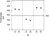
Fig. 6 draws according to another n-lustrative of the various porous layers of embodiment 2 and the average bonding strength between the metallic matrix;
Fig. 7 draws according to the n-lustrative of the various porous layers of embodiment 3 and the bond strength between the metallic matrix;
Fig. 8 draws in conjunction with the n-lustrative of tantalum Concentraton gradient in sample and the resistance welded sample for diffusion;
Fig. 9 draws in conjunction with the n-lustrative of tantalum Concentraton gradient in sample and the resistance welded sample for diffusion;
Figure 10 is in conjunction with the porous member of sample and the scanning electron microscope image of the acquisition of the separating surface between the matrix along diffusion;
Figure 11 is the scanning electron microscope image along the porous member of resistance welded sample and the acquisition of the separating surface between the matrix;
Figure 12 draws according to another n-lustrative of the various porous layers of embodiment 6 and the bond strength between the metallic matrix;
Figure 13 is the scanning electron microscope image that obtains along porous layer and the separating surface between the metallic matrix according to embodiment 6;
Figure 14 is the scanning electron microscope image that obtains along porous layer and the separating surface between the metallic matrix according to embodiment 7;
Figure 15 draws according to another n-lustrative of the various porous layers of embodiment 7 and the bond strength between the metallic matrix.
The identical parts of reference number representative that several views are identical from the beginning to the end.The exemplary plot that herein represents has illustrated exemplary embodiment of the present, and these examples constitute limiting the scope of the invention never in any form.
The specific embodiment
See figures.1.and.2, it is for example hipbone handle of proximal femurs member 10(that form is provided) cosmetic prosthesis.Though describe here and figure has painted the cosmetic prosthesis of proximal femurs member 10 forms, cosmetic prosthesis also can be the form of distal femoral member, tibia member, acetabular bone member or humerus member for example.
The proximal femurs member 10 of Fig. 1 comprises shank 12 and cervical region 14, and described neck construction becomes receiver module head (not shown).Belong to equally in the application's scope is that this head can one be connected to cervical region 14.In use, by the shank 12 of near-end femoral component 10 being implanted the pulp cavity of patient's proximal femurs, the cervical region 14 of proximal femurs member 10 medially extends to be connected with patient's the natural acetabular bone or the acetabular bone member joint of prosthese from patient's proximal femurs with the head (not shown).The shank 12 of proximal femurs member 10 comprises dermoskeleton contact surface 18, and it is configured to contact the bone and/or the soft tissue of patient's femur.
As shown in Figure 2, proximal femurs member 10 comprises metallic matrix 20 and porous metallic layers 22, and described porous metallic layers 22 is connected to the matrix 20 that is positioned under it.Porous layer 22 can be placed in the recess 26 of matrix 20.Define at least a portion of bone contact surface 18 by porous layer 22, the bone of patient's femur and/or soft tissue can grow into porous layer 22 to strengthen fixing (being the bone integration) between proximal femurs member 10 and the patient's femur in the course of time.
The matrix 20 of proximal femurs member 10 can comprise the biocompatibility metal such as titanium, titanium alloy, cobalt chromium, cobalt chrome molybdenum, tantalum or tantalum alloy.According to exemplary embodiment of the present invention, matrix 20 comprises Ti-6Al-4V ELI alloy, for example can obtain from the Zimmer company of Indiana state Warsaw

 It is the registered trade mark of Zimmer company.
The porous layer 22 of proximal femurs member 10 can comprise the biocompatibility metal such as titanium, titanium alloy, cobalt chromium, cobalt chrome molybdenum, tantalum or tantalum alloy.Porous layer 22 can be the form of highly porous biomaterial, and this accepts material as bone substitute and cell and soft tissue is useful.Be in equally and in the scope of the invention be, for example, porous layer 22 can be a fibre metal pad or such as Cancellous-Structured Titanium
TM(CSTi
TM) form of sintered metal layer of layer.CSTi
TMPorous layer is made by the Zimmer company of Indiana state Warsaw.Cancellous-Structured Titanium
TMAnd CSTi
TMIt is the trade mark of Zimmer company.
Highly porous biomaterial can have low to 55%, 65% or 75% and high to 80%, 85% or 90%, perhaps is in the porosity in any range that is limited between the arbitrary pairing of aforementioned value.Such examples of material is highly porous fibre metal pad.The another example of such material is CSTi
TMLayer.Another example of such material uses the Trabecular Metal that can obtain from the Zimmer company of Indiana state Warsaw substantially
TMTechnology is produced.Trabecular Metal
TMIt is the trade mark of Zimmer company.Such material can be formed by the vitreous carbon foam base plate of net form, by in U.S. Patent No. 5,282, in 861 with the disclosed chemical vapour deposition (CVD) of detailed mode (" CVD ") technology, the biocompatibility metal infiltration and the coating of this matrix adopting such as tantalum, this patent publication us clearly is incorporated into this by reference.Except tantalum, also can use other such as columbic metal or tantalum and niobium alloys each other or tantalum and niobium and other metals.
Substantially, the porous tantalum structure comprises a large amount of fiber (ligament), and fiber defines therebetween open space, and each fiber for example comprises the carbon core that is covered by the metallic film such as tantalum substantially.Open space between the fiber has formed does not have the continuous passage of end substrate (matrix), makes that spongy bone is uncontrolled through the growth of porous tantalum structure.Porous tantalum can comprise therein up to 75%-85% or more void space.Thereby porous tantalum is the loose structure of light weight, brute force, described loose structure is unified substantially with consistent on component, and exactly like the structure of natural spongy bone, can grow into wherein substrate so that proximal femurs member 10 fixing to patient's femur to be provided thereby be provided with spongy bone.
In order optionally to be the customized structure of application-specific, the porous tantalum structure can be made with different density.Especially as above bonded U.S. Patent No. 5,282, described in 861, porous tantalum can manufacture any in fact porosity of wanting and pore-size, and thereby can be complementary with natural bone on every side so that inwardly growth and mineralising provide optimized substrate for skeleton.
The aforesaid Trabecular Metal of porous layer 22 employings when proximal femurs member 10
TMWhen technology was produced, the matrix 20 of little percentage can directly contact with the fiber of porous layer 22.For example approximate 15%, 20% or 25% of the surface area of matrix 20 can directly contact with the fiber of porous layer 22.
Next with reference to Fig. 3, provide equipment 100 to be used for the matrix 20 of porous layer 22 resistance welded to proximal femurs member 10.Equipment 100 also schematically illustrates in Fig. 4 A and Fig. 4 B.Equipment 100 comprises housing 110, comprises one or more supports or fixture 120a, 120b in housing 110, one or more plumb joint 130a, 130b, and each plumb joint has electrode 132a, 132b; Described equipment comprises transformator 140, power supply or current feedback circuit 150 and controller 160.Each member of equipment 100 is further in following description.
The housing 110 of equipment 100 defines internal chamber 112, and described internal chamber size is set to receive at least one prosthese such as the proximal femurs member 10 of Fig. 1 and Fig. 2.According to exemplary embodiment of the present invention, during the resistance welded process, the housing 110 of equipment 100 has been made vacuum environment or inert environments in chamber 112.In a special embodiment, the chamber 112 of housing 110 charges into noble gas (for example argon) and is controlled to has-60 ° of dew point and following oxygen concentrations of about 10ppm that C is following approximately.
The fixture 120a of equipment 100,120b contact proximal femurs member 10 is to be held in place near-end femoral component 10 in the housing 110 of equipment 100.Fixture 120a, 120b can move to open position (Fig. 4 A) dividually with reception proximal femurs member 10, and to moving to closure or clip position (Fig. 4 B) together so that near-end femoral component 10 is held in place.Belong in the scope of the invention is that the make position of fixture 120a, 120b can be regulated so that equipment 100 can receive and keep the prosthese of difformity and size.
Electrode 132a, 132b on plumb joint 130a, the 130b of equipment 100 is connected to transformator 140 and current feedback circuit 150 via electric wire 152a, 152b respectively.As shown in Fig. 4 A, each electrode 132a, 132b are towards the respective side of porous layer 22.More specifically, contact surface 134a, the 134b of each electrode 132a, 132b are towards the respective side of porous layer 22.According to exemplary embodiment of the present invention, contact surface 134a, the 134b of each electrode 132a, 132b is designed to substantially the profile phase coupling with the respective side of porous layer 22.In this embodiment, each electrode 132a, 132b can be caught close even contact proximal femurs member 10.The shape that depends on proximal femurs member 10, corresponding contour surface 134a, 134b can for example be recessed, protruding or smooth.
Alternatively, equipment 100 can comprise additional support or fixture (not shown), and described support or fixture are configured to keep porous layer 22 against matrix 20 during the resistance welded process.More particularly, these additional fixtures can be configured to during the resistance welded process porous layer 22 be remained in the recess 26 of matrix 20.
Employed matrix 20 against proximal femurs member 10 keeps the pressure of porous layer 22 can sufficiently hang down to avoid porous layer 22 distortion or compression still to hinder the motion of porous layer 22 with respect to matrix 20 simultaneously during the resistance welded process.Thereby welding pressure should be no more than the compression yield strength of matrix 20 or porous layer 22.For example, if the compression yield strength of porous layer 22 is about 4000psi(27.6MPa), so the welding pressure of Shi Heing can for example hang down to 100psi(0.7MPa), 500psi(3.4MPa) or 1000psi(6.9MPa), with height to 2000psi(13.8Mpa), 2500psi(17.2MPa) or 3000psi(20.7MPa), perhaps be in any range that is limited between the arbitrary pairing of aforementioned value.Porous layer 22 can be set as final substantially shape to avoid having to compress or otherwise make porous layer 22 molding during the resistance welded process before the resistance welded process.As a result, the contact area between the thickness of porous layer 22 and porous layer 22 and the matrix 20 can remain unchanged during the resistance welded process substantially.As mentioned above, when plumb joint 130a, 130b were in the close position (Fig. 4 B), welding pressure can be applied and/or be applied by equipment 100 additional fixture (not shown) by plumb joint 130a, 130b.
In use, proximal femurs member 10 is loaded onto in the housing 110 of equipment 100.Along with porous layer 22 is suitably settled against the matrix 20 of proximal femurs member 10, controller 160 can be operated so that fixture 120a, 120b and/or plumb joint 130a, 130b are moved from their open positions (Fig. 4 A) separately towards their make positions (Fig. 4 B) separately.Can be near pressure (that is before, fixture 120a, 120b and/or plumb joint 130a, 130b contact with proximal femurs member 10 near the pressure of proximal femurs member 10) less than above-mentioned welding pressure to avoid damaged member.For example, can hang down 10psi(0.07MPa near pressure), 30psi(0.2MPa) or 50psi(0.3MPa) and high to 70psi(0.5MPa), 90psi(0.6MPa) or 110psi(0.8MPa), perhaps be in any range that is limited between the arbitrary pairing of aforementioned value.
After proximal femurs member 10 was loaded onto in the housing 110 of equipment 100, controller 160 can be operated with the chamber 112 of the housing 110 of finding time and/or charge into the chamber 112 of housing 110 with noble gas (for example argon).Vacuum in the housing 110 of equipment 100 or inert environments can prevent proximal femurs member 10 oxidation during the resistance welded process substantially, absorb atmosphere pollution and/or become and fade.
Next, controller 160 can be operated to cause that electric current flow to transformator 140 from current feedback circuit 150.Current feedback circuit 150 can be for example with 4kJ, 6kJ, 8kJ, 10kJ or bigger power operation.Along with contact surface 134a, the 134b of each electrode 132a, 132b porous layer 22 location against proximal femurs member 10, welding current is from an electrode (for example via electric wire 152a from the electrode 132a) proximal femurs of flowing through member 10, and flows out from another electrode (for example via electric wire 152b from electrode 132b).In the exemplary embodiment, source electrode 132a, 132b can be with for example low to 20kA, 30kA or 40kA and high to 50kA, 60kA or 70kA, the welding current that perhaps is in any range that is limited between the arbitrary pairing of aforementioned value is delivered to proximal femurs member 10, and is low to 25kA/in to produce
2(3.9kA/cm
2), 35kA/in
2(5.4kA/cm
2) or 45kA/in
2(7.0kA/cm
2) and high to 55kA/in
2(8.5kA/cm
2), 65kA/in
2(10.1kA/cm
2), 75kA/in
2(11.6kA/cm
2) or 85kA/in
2(13.2kA/cm
2), perhaps be in the welding current density in any range that is limited between the arbitrary pairing of aforementioned value.When welding current was flowed through proximal femurs member 10, controller 160 can be maintained fixed the welding pressure of device 120a, 120b and/or plumb joint 130a, 130b.
According to Ohm's law (P=I
2* R), the porous layer 22 of the proximal femurs of flowing through member 10 and the welding current I of matrix 20 distribute as heat, and it is proportional to be accompanied by heat and resistance R that the place, arbitrfary point in circuit produces.When adopting different material construction porous layers 22 and matrix 20, the separating surface place of resistance R between porous layer 22 and matrix 20 can be the highest.Therefore, the contact point place between porous layer 22 and matrix 20 can produce a large amount of heats partly.
According to exemplary embodiment of the present invention, the heat that produces is enough to cause the softening and/or hot melt of the material that is used to make up porous layer 22 and/or matrix 20, in conjunction with the welding pressure that is used for keeping against matrix 20 porous layers 22, described softening and/or hot melt makes and combines with contact point place generation surface metallurgic between the matrix 20 at porous layer 22.What belong to the scope of the invention equally is that metallurgical binding can take place at the contact point place in the porous layer 22.For example, if porous layer 22 forms are the fibre metal pad, metallurgical binding can take place at the contact point place between the adjacent wires in the fibre metal pad so.
In accordance with a further exemplary embodiment of the present invention, welding current can be discrete but be delivered to proximal femurs member 10 in the pulse rapidly.Welding current can be for example with few to 4,6 or 8 pulses with how be delivered to proximal femurs member 10 to 10,12 or 14 pulses or with the pulse of any numerical value therebetween.Each pulse can for example be short to 20 milliseconds, 40 milliseconds or 60 milliseconds and long to 80 milliseconds, 100 milliseconds or 120 milliseconds or any therebetween numerical value.Between each pulse, the disappearance of welding current can promote a large amount of coolings of porous layer 22 and matrix 20 in the mode of heat on partial, the separating surface of not eliminating porous layer 22 and matrix 20.Can be less than 1 second the cool time between each pulse, and more specifically can for example be short to 20 milliseconds, 40 milliseconds or 60 milliseconds and long to 80 milliseconds, 100 milliseconds or 120 milliseconds or any therebetween numerical value.
As mentioned above, during the resistance welded process, be used for keeping the welding pressure of porous layer 22 should hang down fully to avoid porous layer 22 distortion against matrix 20.Because matrix 20 is along interfacial softening and/or hot melt, porous layer 22 can slightly move or translation and can becoming is imbedded in the remollescent matrix 20 towards remollescent matrix 20.Therefore, the gross thickness of proximal femurs member 10 (be porous layer 22 and matrix 20 in conjunction with thickness) can reduce during the resistance welded process.For example, during the resistance welded process, the gross thickness of proximal femurs member 10 can reduce approximate 0.1%, 0.2%, 0.3% or more.Yet porous layer 22 thickness own should not change significantly.In other words, any change that measures on proximal femurs member 10 thickness should be moved in the remollescent matrix 20 and caused by porous layer 22, rather than is caused by the compression of porous layer 22 itself or distortion.When porous layer 22 forms are the fibre metal pad, owing to form metallurgical binding in the porous layer 22, so porous layer 22 can bear certain distortion (for example shrinkage).Yet this distortion should be owing to welding pressure.
After electric current is delivered to proximal femurs member 10, matrix 20 and porous layer 22 will begin to cool down.During this period, controller 160 can be operated with the forging pressure on the retaining member.The comparable above-mentioned welding pressure of forging pressure (promptly after welding current finished, fixture 120a, 120b and/or plumb joint 130a, 130b kept the pressure of proximal femurs member 10) is little.For example, forging pressure can hang down 40psi(0.3MPa), 60psi(0.4MPa) or 80psi(0.6MPa) and high to 100psi(0.7MPa), 120psi(0.8MPa) or 140psi(1.0MPa), perhaps be in any range that is limited between the arbitrary pairing of aforementioned value.Forging time can for example be short to 1 second, 2 seconds or 3 seconds and long by 4 seconds, 5 seconds or more.
Generally speaking, employing equipment 100 with porous layer 22 resistance welded to the 20 required times of matrix for example can be short to 1 second, 10 seconds, 20 seconds or 30 seconds and long by 1 minute, 2 minutes, 3 minutes or more.Depend on the thickness of porous layer 22, by electric current and other parameters that current feedback circuit produces, the required time can change.
At last, controller 160 can be operated so that fixture 120a, 120b and/or plumb joint 130a, 130b are back to their open positions (Fig. 4 A) separately.Proximal femurs member 10 can remove with the housing 110 that porous layer 22 is firmly-fixed to the mode slave unit 100 of matrix 20 subsequently.
Advantageously, by with porous layer 22 resistance welded to matrix 20, between porous layer 22 and matrix 20, can realize firm metallurgical binding.In certain embodiments, the bond strength between porous layer 22 and the matrix 20 can be at least 2900psi(20.0MPa), this bond strength is the bond strength that is used for the shaping implantation that FDA recommends.And, because resistance welded comprises heating and the short circulation time of needs on partial, the separating surface of porous layer 22 and matrix 20, so the deterioration of porous layer 22 and matrix 20 can be avoided.As a result, during the resistance welded process, the fatigue strength of matrix 20 and porous layer 22 can not change substantially.
Although porous layer 22 is in this description and depict the matrix 20 that directly is bonded to proximal femurs member 10 as, yet what also belong to the scope of the invention is that porous layer 22 can be bonded to the intermediate layer (not shown) in advance, and described intermediate layer is bonded to matrix 20 subsequently.The intermediate layer that is fit to can for example comprise titanium foil.Subsequently integrating step all can comprise the above-mentioned resistance welded with reference to Fig. 3, Fig. 4 A and Fig. 4 B between pre-integrating step between porous layer 22 and the intermediate layer and intermediate layer and the matrix 20.Yet what also belong to the scope of the invention is that integrating step can comprise traditional diffusion and combines between subsequently intermediate layer and the matrix 20.
Embodiment
1. embodiment 1-Trabecular Metal
TMThe analysis of surface finishing and thickness
Prepared a series of samples, each sample has the Trabecular of use Metal
TMThe plate-like porous member that technology is produced and discous
 Matrix.Described matrix is identical substantially, but porous member aspect two, have any different, i.e. surface finishing and thickness are as listed in the following table 1.
Table 1

Before corresponding matrix is placed against it with the dividing surface of each porous member, listed handling in the dividing surface of each porous member such as the above table 1.
In group 1, the dividing surface of each porous member stands discharge processing (EDM), and the outstanding fiber of some of its porous member that fractures and make dividing surface smooth makes the how available fiber contact matrix below at the release surface place.Therefore, EDM has moderately increased the net contact area of organizing porous member in 1.
In group 2, each porous member be set as net form (net shape) and after making the dividing surface of each porous member do not stand to process, so kept the volume porosity rate of porous member at the dividing surface place.More specifically, netted dividing surface is by with the outer surface of washing loose structure (being netted vitreous carbon foaming structure) and keep surface outside, that apply to produce in the mode of not outer surface processing or molding subsequently.Therefore, the net contact area of porous member is kept in the group 2.
In group 3, the dividing surface of each porous member stands Physical Processing with the some fibre of the porous member that fractures and other fibers of expansion or " smearing " porous member, and this causes the remarkable minimizing of the surface porosity factor of dividing surface.Therefore, smear and increased the net contact area of organizing porous member in 3.
These surface-treateds are the result be, group 2 porous member has with the minimum surface of matrix below and contacts, and have with the maximum surface of below matrix and contact and organize 3 porous member.
Sample is assembled by resistance welded subsequently.The power that applies first magnitude is welded on their corresponding matrixes with 0.060 inch (1.5mm) is thick and 0.125 inch (3.2mm) thick porous member ( group 1A, 1B, 2A, 2B, 3A and 3B).The second magnitude power that applies than the first magnitude power big 50% is welded on their corresponding matrixes with the porous member that 0.250 inch (6.4mm) is thick ( group 1C, 2C and 3C).Each is organized the average bonding strength of the sample of 1-3 and draws to n-lustrative in Fig. 5.
As shown in Figure 5, group 2 sample is compared group 1 or is organized 3 sample and has higher average bonding strength.Contact because organize the surface that 1 sample of comparing group 2 with group 3 porous member has more matrix with below, so the inventor suspects that striding across electric current that bigger surperficial contact area applied and dispersed heat has caused for group 1 and organize to compare for 3 the sample and organize the more weak combination of 2 samples.On the contrary, compare the sample of group 1 and group 3 and have the surface with matrix below still less and contact because organize 2 porous member, thus the inventor suspect the electric current that applies with each minute other fiber place localization heat caused for the sample of group 2, comparing group 1 and the stronger combination of sample of organizing 3.
And in each group 1-3, the sample that the sample of son group A and C is compared respective sub-set B has higher average bonding strength.For example, group 2A has higher average bonding strength with the sample that the sample of group 2C is compared group 2B.
In each group 1-3 from the reduction of child group A to B bond strength be attributable to porous member from 0.060 inch to 0.125 inch the thickness that is increased.Because the thermal conductivity of tantalum in each porous member (approximately 54W/m/K) is greater than the thermal conductivity (approximately 7W/m/K) of tantalum in each matrix, so the thicker porous member of each son group B can serve as radiator, will advance in the space of porous member away from separating surface and conduction in the heat conduction that separating surface produces.
In each group 1-3, be attributable to be used for the first magnitude power of the thick and 0.125 inch thick porous member of 0.060 inch of resistance welded and be used between the second magnitude power of 0.250 inch thick porous member of resistance welded 50% increase from the increase of child group B to C bond strength.The power that increases has produced the electric current that increases, and it causes bigger heating and stronger combination.
2. embodiment 2-Trabecular Metal
TMThe analysis of thickness, bonding power and weld cycle number of times
Prepared other a series of sample, each sample has the Trabecular of use Metal
TMThe plate-like porous member that technology is produced and discous
 Matrix.Because the porous member of net form in embodiment 1 (group 2) has been realized the highest bond strength, so the porous member of embodiment 2 also is set to net form.Matrix is identical substantially, but porous member is different on thickness.And the resistance welded process is distinguished aspect two to some extent, i.e. the number of times of power and weld cycle (weld cycle) is as listed in the following table 2.
Table 2

The average bonding strength of the sample of each group 4-6 is drawn to n-lustrative in Fig. 6.Group 4 has higher average bonding strength with the sample that the sample of group 6 is compared group 5.In fact, group 4 and group 6 sample have 4000psi(27.6MPa) above average bonding strength, this average bonding strength has surpassed the 2900psi(20.0MPa that FDA recommends) bond strength.
What change in the bond strength about 90.6% is attributable to the thickness that porous member changes and the bonding power of variation.The number of times of finding weld cycle seems unimportant on statistics.
3. embodiment 3-Trabecular Metal
TMThe analysis of thickness and weld interval
Prepared other a series of circular sample, each sample has the Trabecular of use Metal
TMThe plate-like porous member that technology is produced and discous
 Matrix.Contact area between each porous member and the matrix below it is about 5 square inches of (32.3cm
2).Matrix is identical substantially, but porous member is different on thickness.As listed in the following table 3, the resistance welded circulation time is also different.
Matrix.Contact area between each porous member and the matrix below it is about 5 square inches of (32.3cm
2).Matrix is identical substantially, but porous member is different on thickness.As listed in the following table 3, the resistance welded circulation time is also different.
Table 3
After the described sample of resistance welded, downcut the sample of two 1.2 inches (3.0cm) diameters to be used for extension test from each sample.The bond strength of each sample of group 7 and group 8 is drawn to n-lustrative in Fig. 7.As shown in Figure 7, one of them of two samples of group 8B has the 2900psi(20.0MPa that recommends than FDA) the bigger bond strength of bond strength.Yet another sample of group 8B has 1000psi(6.9MPa) following bond strength.
The variation of the bond strength between the respective samples may be because the pressure heterogeneous and/or the electric current of each sample of process.The physical detection of the retained material that stays after the sample that cuts away 1.2 inches (3.0cm) diameters has confirmed the discovery of bond strength variation grades in each sample.
4. embodiment 4-resistance welded and the comparison of diffusion between combining
Except extension test, also carried out the metallography test with the combination that relatively realizes by resistance welded and by diffusion in conjunction with the combination that realizes.
When porous member diffusion is bonded to below matrix, from the atom of porous member and atom counterdiffusion mutually from matrix.For example, when adopting Trabecular Metal
TMThe porous member diffusion that technology is produced is attached to
 During matrix, the tantalum that comes from porous member diffuses in the matrix, and the titanium that comes from matrix diffuses in the porous member.Tantalum enters being diffused among Fig. 8 of matrix and illustrates to n-lustrative, and titanium enters being diffused among Fig. 9 of porous member and illustrates to n-lustrative.The phase counterdiffusion of tantalum and titanium has been made along interfacial Concentraton gradient between porous member and the matrix or diffusion layer mutually.Porous member also illustrates in Figure 10 visibly with diffusion layer mutually between the matrix, and this figure is the scanning electron microscope image that obtains in conjunction with separating surface between the porous member of sample and the matrix along diffusion.
When porous member by resistance welded during to below matrix, rare or the phase counterdiffusion do not take place.For example, the tantalum concentration in Fig. 8 in the porous member keeps constant substantially, and the titanium concentration in the matrix keeps constant substantially in Fig. 9.The disappearance of any significant diffusion layer mutually between porous member and the matrix also illustrates in Figure 11 visibly, and this figure is the scanning electron microscope image that obtains along separating surface between the porous member of resistance welded sample and the matrix.
5. the analysis of embodiment 5-welding pressure
Prepared the disk samples that a series of diameters are 1 inch (2.5cm), the electrode separating surface of each sample has about 0.79 square inch of (5.1cm
2) surface area.Each sample have 0.055 inch (1.4mm) thickness, adopt Trabecular Metal
TMThe porous member that technology is produced and 0.130 inch (3.3mm) thickness
Matrix.Welding pressure is calculated as 4160psi(28.7MPa), it can be compared with the compression yield strength of porous member.The result of this high welding pressure is, the weld period porous member partly be squeezed and average thickness reduce about 0.022 inch (0.6mm) or reduce 40%(from 0.055 inch (1.4mm) to 0.033 inch (0.8mm)).
6. the analysis of embodiment 6-pulse welding
The disk samples that to have prepared other a series of diameter be 1 inch (2.5cm), each sample have 0.055 inch (1.4mm) thickness, adopt Trabecular Metal
TMThe porous member that technology is produced and 0.130 inch (3.3mm) thickness
 Matrix.Each porous member comprises the EDM molded surface with the matrix boundary.The resistance welded parameter of
 embodiment 6 is following to be listed in table 4.
Table 4
| Welding parameter | Setting value |
| Near pressure | 20psi |
| Near the time | 3 seconds |
| Welding pressure | 800psi |
| Forging pressure | 45psi |
| Forging time | 3 seconds |
| Current intensity | 24kA |
| Electric current density | 30kA/in 2 |
| Controlled atmosphere | Argon dew point<-60 ℃ oxygen concentration<10ppm |
List in table 5 as following, the welding current pulse of each sample reception varying number, continue 80 milliseconds the cool time between 80 milliseconds of each pulse persistances and each pulse.Sample 1-5 is prepared to estimate up to 10 pulses.Sample 6-11 is prepared more specifically to estimate the pulse between 5 and 10.
Table 5
| Sample | Number of pulses |
| 1 | 1 |
| 2 | 4 |
| 3 | 6 |
| 4 | 8 |
| 5 | 10 |
| 6 | 5 |
| 7 | 6 |
| 8 | 7 |
| 9 | 8 |
| 10 | 9 |
| 11 | 10 |
Design and build a kind of novel resistance welding equipment in controlled environment, to carry these welding current pulses.Described equipment comprises the AX5000 atmospheric exposure device with BMI-500 single-column gas purge system, KN-II outstanding plumb joint, IT-1400-3 transformator and the ISA-2000CR inverter with refrigerative copper alloy electrode, and all these can obtain from the Miyachi Unitek company of California state Monrovia.
The general thickness of each sample before welding with keep identical afterwards substantially, show the lower 800psi(5.5MPa of embodiment 5) welding pressure successfully eliminated the distortion and the extruding of above porous member seen in the embodiment 4.
Sample 1-5 stands extension test.The bond strength of weld part is from for a sample 1(1 pulse) 0psi(0MPa) increase to a pulse for sample 3(6) and 6882psi(47.4MPa).For a sample 4(8 pulse) with a sample 5(10 pulse) for the bond strength of weld part keep approximate identical.
Sample 6-11 stands extension test and regression analysis subsequently, and its result draws to n-lustrative in Figure 12.As shown in Figure 12, bond strength is accompanied by each additional pulse increases.95% lower forecast interval on 9 weld pulses with 2900psi(20.0MPa) reference line intersects (seeing annular cross point among Figure 12).Thereby, for given welding parameter, need at least 10 weld pulses to produce the bond strength of 2900psi at least constantly.
The visual check of sample shows not only along form the heat affected area that can notice in conjunction with separating surface (being the separating surface between porous member and the matrix) but also along electrode separating surface (being the separating surface between sample and the resistance welded electrode).Because the heat that produces during the resistance welded process changes so sample can experience distortion, infiltration and/or micro structure in such heat affected area.For example, Figure 13 figure draws the heat affected area in conjunction with separating surface formation along above sample 1.Possible and what belong to the scope of the invention is after the resistance welded process electrode separating surface to be machined away or otherwise remove.Yet, after the resistance welded process, can not remove in conjunction with separating surface not damage bonded mode.
7. embodiment 7-at the analysis of the porous member of net form for the pulse welding current that reduces the heat affected area
In order to eliminate above heat affected area seen in the embodiment 6, prepared other a series of diameter the disk samples that is 1 inch (2.5cm), each sample have 0.055 inch (1.4mm) thickness, adopt Trabecular Metal
TMThe porous member that technology is produced and 0.130 inch (3.3mm) thickness
 Matrix.Be different from
 embodiment 6, each porous member comprises net form rather than the EDM molding and separating surface matrix.And, than embodiment 6, stand cool time longer between shorter weld pulse, the pulse, higher welding pressure and higher welding current intensity at sample during the resistance welded.The resistance welded parameter of embodiment 7 is following to be listed in table 6.
Table 6
| Welding parameter | Setting value |
| Near pressure | 20psi |
| Near the time | 3 seconds |
| Welding pressure | 1000psi |
| Forging pressure | 62psi |
| Forging time | 3 seconds |
| Number of |
10 |
| The weld interval of each pulse | 15 milliseconds |
| Cool time | 250 milliseconds |
| Controlled atmosphere | Argon dew point<-60 ℃ oxygen concentration<10ppm |
As following listed in table 7, the pulse welding current between described sample reception 35kA and the 51kA.

As initial material, the visual check of sample has shown along reducing significantly or eliminate fully in some cases than embodiment 6 in conjunction with the width of interfacial heat affected area and scope.For example, sample 1(Figure 13 of embodiment 6) compare sample 3b(Figure 14 of embodiment 7) have the bigger heat affected area that can notice.Some heat affected areas keep along the electrode separating surface, but as mentioned above, can after the resistance welded process these electrode separating surfaces be machined away or otherwise remove.
Sample stands extension test and regression analysis equally, and its result illustrates to n-lustrative in Figure 15.As shown in Figure 15, bond strength increases when the welding current of each pulse increases.95% lower forecast interval is at about each pulse 43kA place and 2900psi(20.0MPa) reference line crossing (seeing annular cross point among Figure 13).Thereby, with given welding parameter, need at least the welding current of each pulse 43kA (perhaps each pulse 54kA/in at least
2(8.4kA/cm
2) welding density) to produce the bond strength of 2900psi at least constantly.
Additional sample is with each pulse 46kA(or with about each pulse 58kA/in
2(9.0kA/cm
2) welding density) welding to be confirming this result, but bond strength is inconsistent and scope from 2387psi(16.5MPa) to 4246psi(29.3MPa).Equally, the visual check of these additional samples has showed along the heat affected area of noticing in conjunction with interface energy.The inventor with these inconsistent results at least in part owing to wear to electrodes and metal transfer to electrode.
8. embodiment 8-at the analysis of the porous member of EDM molding for the pulse welding current that reduces the heat affected area
9. embodiment 9-for reducing electrode damage and improving the analysis of the welding pressure and the pulse welding current of bond strength
In order to improve the result of embodiment 7, comprise and reduce wear to electrodes substantially and metal transfer to electrode, with higher 40psi(0.3MPa) near pressure, higher 2000psi(13.8MPa) welding pressure and lower 55psi(0.4MPa) forging pressure repeat embodiment 7.According to embodiment 7, sample stands greater than 43kA, the pulse welding current between 45kA and 61kA particularly.
With the higher welding pressure (2000psi) of embodiment 9, the inventor notices that sample compares with the adhesion between the electrode with the lower welding pressure (1000psi) of embodiment 7 still less.The inventor believes that higher welding pressure has increased contacting between sample and the electrode, and thereby has reduced the resistance between sample and the electrode and the heat of generation.
Sample has stood extension test and regression analysis, and it has shown the needs welding current of each pulse 59kA (or each pulse 75kA/in at least at least
2(11.6kA/cm
2) welding density) to produce 2900psi(20.0MPa at least constantly) and bond strength.
Nine additional samples weld with about each pulse 59kA and confirm this result, and the bond strength average out to 4932psi(34.0MPa of these nine additional samples), scope is from 3174psi(21.9MPa) to 6688psi(46.1MPa).And the visual check of these nine additional samples has shown along the minimum in conjunction with the separating surface heat affected area and has existed.
Six additional samples are with approximately each pulse 61kA(or approximately each pulse 77kA/in
2(11.9kA/cm
2) welding density) welding further confirms this result.Before comparing, wherein matrix is 0.130 inch test that (3.3mm) is thick, each of these additional samples has thicker a little matrix, is specially 0.170 inch matrix that (4.3mm) is thick.The bond strength average out to 3968psi(27.4MPa of these additional samples), scope is from 3259psi(22.5MPa) to 4503psi(31.0MPa).In all these additional samples, in porous material rather than along combining separating surface generation tensile failure between porous material and the matrix.And the visual check of these samples has shown along there is not macroscopic heat affected area in conjunction with separating surface.In addition, the visual check of these samples shown along the interfacial microstructure change of electrode, but changes with the degree of depth very shallow, that can the remove degree of depth of (for example less than 0.020 inch (0.5mm)).
Although described the present invention as having exemplary design, yet the present invention can further revise in spirit and scope of the present disclosure.Therefore the application is intended to cover remodeling, use or the reorganization of the invention of adopting its general principle.In addition, the application be intended to cover from disclosure amplification, as being in the known in the technical field of the invention or habitual practical framework and dropping on scheme in the restriction of claims.
Claims (20)
1. a method of making cosmetic prosthesis is characterized in that, described method comprises the steps:
Metallic matrix is provided;
Porous metallic layers with thickness is provided;
Porous layer is located to form the separating surface between porous layer and the matrix against matrix; And
The separating surface that electric current is guided between porous layer and the matrix keeps porous layer thickness simultaneously porous layer is bonded to matrix.
2. method according to claim 1 is characterized in that X.
3. method according to claim 1 is characterized in that, guides step to comprise porous layer is contacted with electrode, and electric current is advanced through porous layer and towards matrix from electrode.
4. method according to claim 1 is characterized in that, described method comprises also and apply the step of welding pressure so that porous layer is kept against matrix that wherein welding pressure is enough low to avoid porous layer to be out of shape.
5. method according to claim 4 is characterized in that welding pressure is less than 3000psi(20.7MPa).
6. method of making cosmetic prosthesis, described cosmetic prosthesis has metallic matrix and porous metallic layers, it is characterized in that, and described method comprises the steps:
Porous layer is located to form the separating surface between porous layer and the matrix against matrix; And
Pulse current is guided to separating surface between porous layer and the matrix so that porous layer is bonded to matrix, second pulse that pulse current comprises at least the first pulse and be cooled time and first pulse are separated.
7. method according to claim 6 is characterized in that described pulse current comprises at least 10 pulses.
8. method according to claim 6 is characterized in that, the guiding step comprises each pulse of pulse current with 75kA/in at least
2(11.6kA/cm
2) electric current density guide to cosmetic prosthesis.
9. method according to claim 6 is characterized in that described cool time was less than 1 second.
10. method according to claim 6 is characterized in that, the guiding step is implemented in the controlled atmosphere that has less than the oxygen concentration of about 10ppm.
11. method according to claim 6 is characterized in that, the guiding step is with 2900psi(20.0MPa) or bigger hot strength is with porous layer and matrix bond together.
12. method according to claim 6 is characterized in that, described method also comprises the steps:
During the guiding step, cosmetic prosthesis is applied welding pressure; And
After the guiding step, the integer prosthese is applied forging pressure.
13. method according to claim 12 is characterized in that forging pressure is lower than welding pressure.
14. a method of making the integer prosthese is characterized in that described method comprises the steps:
Metallic matrix is provided;
Porous metallic layers with net form surface is provided, and the net form surface of porous layer forms as follows:
Loose structure with outer surface is provided;
With the outer surface of metal pair loose structure coated with making porous layer; And
After coating step, outer surface machining ground does not keep outer surface to reach the net form surface;
The net form surface of porous layer is located to form the separating surface between porous layer and the matrix against matrix; And
Electric current is guided to separating surface between porous layer and the electrode so that porous layer is bonded to matrix.
15. method according to claim 14 is characterized in that, the net form surface of porous layer is compared porous layer and is had through the surface of machining and matrix contacting still less.
16. method according to claim 14 is characterized in that, the net form surface of porous layer is compared porous layer and has been realized through the surface of machining and stronger the combining of matrix.
17. method according to claim 14 is characterized in that, honeycomb sandwich comprises the vitreous carbon foam of net form.
18. method according to claim 14 is characterized in that, coating step comprises that the chemical vapour deposition (CVD) step is with the outer surface of washing loose structure and use the metal penetration loose structure.
19. method according to claim 14 is characterized in that, the guiding step is implemented in the controlled atmosphere that has less than the oxygen concentration of about 10ppm.
20. an equipment that is used to make cosmetic prosthesis, described cosmetic prosthesis has metallic matrix and porous metallic layers, it is characterized in that, described equipment comprises:
Housing, described housing limits the chamber that has controlled atmosphere, and described chamber size is adjusted into the reception cosmetic prosthesis;
Controller;
Power supply; And
Electrode, described electrode structure becomes to set up the telecommunication between power supply and the cosmetic prosthesis, and described controller guides to cosmetic prosthesis so that porous layer is bonded to matrix with pulse current from power supply.
Applications Claiming Priority (3)
| Application Number | Priority Date | Filing Date | Title |
|---|---|---|---|
| US41497810P | 2010-11-18 | 2010-11-18 | |
| US61/414,978 | 2010-11-18 | ||
| PCT/US2011/061454 WO2012068492A1 (en) | 2010-11-18 | 2011-11-18 | Resistance welding a porous metal layer to a metal substrate |
Publications (1)
| Publication Number | Publication Date |
|---|---|
| CN103221000A true CN103221000A (en) | 2013-07-24 |
Family
ID=45094796
Family Applications (1)
| Application Number | Title | Priority Date | Filing Date |
|---|---|---|---|
| CN2011800554219A Pending CN103221000A (en) | 2010-11-18 | 2011-11-18 | Resistance welding a porous metal layer to a metal substrate |
Country Status (6)
| Country | Link |
|---|---|
| US (2) | US9174297B2 (en) |
| EP (1) | EP2640318B1 (en) |
| CN (1) | CN103221000A (en) |
| AU (1) | AU2011329690B2 (en) |
| CA (1) | CA2818195C (en) |
| WO (1) | WO2012068492A1 (en) |
Cited By (8)
| Publication number | Priority date | Publication date | Assignee | Title |
|---|---|---|---|---|
| US9174297B2 (en) | 2010-11-18 | 2015-11-03 | Zimmer, Inc. | Resistance welding a porous metal layer to a metal substrate |
| US10427235B2 (en) | 2010-11-18 | 2019-10-01 | Zimmer, Inc. | Resistance welding a porous metal layer to a metal substrate |
| CN110773854A (en) * | 2019-12-30 | 2020-02-11 | 骄英医疗器械(上海)有限公司 | Method for preparing connection structure of porous surface structure and substrate |
| CN111084676A (en) * | 2019-12-30 | 2020-05-01 | 骄英医疗器械(上海)有限公司 | Porous surface structure and substrate connecting structure and preparation device |
| CN111449806A (en) * | 2019-12-30 | 2020-07-28 | 雅博尼西医疗科技(苏州)有限公司 | Porous surface structure and substrate connecting structure, preparation method and prosthesis |
| WO2021135930A1 (en) * | 2019-12-30 | 2021-07-08 | 骄英医疗器械(上海)有限公司 | Connecting structure of porous surface structure and substrate, and preparation device |
| WO2021135929A1 (en) * | 2019-12-30 | 2021-07-08 | 骄英医疗器械(上海)有限公司 | Prosthesis based on connection structure of porous surface structure and substrate |
| WO2021135931A1 (en) * | 2019-12-30 | 2021-07-08 | 骄英医疗器械(上海)有限公司 | Method for preparing connection structure of porous surface structure and substrate |
Families Citing this family (9)
| Publication number | Priority date | Publication date | Assignee | Title |
|---|---|---|---|---|
| US8864836B2 (en) | 2008-06-27 | 2014-10-21 | Zimmer, Inc. | ACL accommodating tibial design |
| US8906108B2 (en) * | 2012-06-18 | 2014-12-09 | DePuy Synthes Products, LLC | Dual modulus hip stem and method of making the same |
| US9271839B2 (en) | 2013-03-14 | 2016-03-01 | DePuy Synthes Products, Inc. | Femoral component for an implantable hip prosthesis |
| US9757243B2 (en) | 2014-07-08 | 2017-09-12 | Zimmer, Inc. | Intercondylar component and fin attachment features for use in knee arthroplasty |
| WO2016010701A1 (en) * | 2014-07-16 | 2016-01-21 | Zimmer, Inc. | Resistance welding a porous metal layer to a metal substrate utilizing an intermediate element |
| US9788951B2 (en) | 2014-09-12 | 2017-10-17 | Zimmer, Inc. | Shapeable porous metal implant |
| JP6504134B2 (en) * | 2016-08-26 | 2019-04-24 | マツダ株式会社 | Apparatus and method for joining metal members |
| CN111012551A (en) * | 2019-12-30 | 2020-04-17 | 骄英医疗器械(上海)有限公司 | Prosthesis based on porous surface structure and substrate connecting structure |
| CN112618114A (en) * | 2020-11-27 | 2021-04-09 | 北京市春立正达医疗器械股份有限公司 | Tantalum metal trabecular femoral condyle prosthesis and knee joint replacement body |
Citations (6)
| Publication number | Priority date | Publication date | Assignee | Title |
|---|---|---|---|---|
| FR2215927A1 (en) * | 1973-01-31 | 1974-08-30 | Louyot Comptoir Lyon Alemand | |
| US3852045A (en) * | 1972-08-14 | 1974-12-03 | Battelle Memorial Institute | Void metal composite material and method |
| US4660755A (en) * | 1985-09-09 | 1987-04-28 | Zimmer, Inc. | Method for constructing a surgical implant |
| US4829152A (en) * | 1987-11-16 | 1989-05-09 | Rostoker, Inc. | Method of resistance welding a porous body to a substrate |
| US6214049B1 (en) * | 1999-01-14 | 2001-04-10 | Comfort Biomedical, Inc. | Method and apparatus for augmentating osteointegration of prosthetic implant devices |
| CN101283936A (en) * | 2008-05-29 | 2008-10-15 | 上海交通大学 | Local spatial grid structure artificial joint prosthesis and preparation method thereof |
Family Cites Families (33)
| Publication number | Priority date | Publication date | Assignee | Title |
|---|---|---|---|---|
| US4164794A (en) | 1977-04-14 | 1979-08-21 | Union Carbide Corporation | Prosthetic devices having coatings of selected porous bioengineering thermoplastics |
| GB8318483D0 (en) | 1983-07-08 | 1983-08-10 | Zimmer Deloro Surgical Ltd | Skeletal implants |
| US4636219A (en) * | 1985-12-05 | 1987-01-13 | Techmedica, Inc. | Prosthesis device fabrication |
| US5018285A (en) | 1987-08-24 | 1991-05-28 | Zimmer, Inc. | Method of constructing prosthetic implant with wrapped porous surface |
| US4990163A (en) | 1989-02-06 | 1991-02-05 | Trustees Of The University Of Pennsylvania | Method of depositing calcium phosphate cermamics for bone tissue calcification enhancement |
| US5074313A (en) | 1989-03-20 | 1991-12-24 | Cardiac Pacemakers, Inc. | Porous electrode with enhanced reactive surface |
| US5118400A (en) | 1990-01-29 | 1992-06-02 | Spire Corporation | Method of making biocompatible electrodes |
| US5282861A (en) | 1992-03-11 | 1994-02-01 | Ultramet | Open cell tantalum structures for cancellous bone implants and cell and tissue receptors |
| US5443510A (en) | 1993-04-06 | 1995-08-22 | Zimmer, Inc. | Porous coated implant and method of making same |
| US5504300A (en) * | 1994-04-18 | 1996-04-02 | Zimmer, Inc. | Orthopaedic implant and method of making same |
| US5947893A (en) | 1994-04-27 | 1999-09-07 | Board Of Regents, The University Of Texas System | Method of making a porous prothesis with biodegradable coatings |
| US5734959A (en) | 1995-10-12 | 1998-03-31 | Zimmer, Inc. | Method of making an orthopaedic implant having a porous surface using an organic binder |
| US5801104A (en) | 1995-10-24 | 1998-09-01 | Micron Technology, Inc. | Uniform dielectric film deposition on textured surfaces |
| JP3740858B2 (en) * | 1997-09-16 | 2006-02-01 | マツダ株式会社 | Joined metal member and method of joining the member |
| JP4173573B2 (en) * | 1997-12-03 | 2008-10-29 | 株式会社ナノテム | Method for producing porous abrasive wheel |
| US6127596A (en) | 1998-01-23 | 2000-10-03 | Sulzer Orthopedics Inc. | Implantable orthopedic prosthesis having tissue attachment surface and method of manufacture |
| US6063442A (en) * | 1998-10-26 | 2000-05-16 | Implex Corporation | Bonding of porous materials to other materials utilizing chemical vapor deposition |
| US6395327B1 (en) | 1999-03-12 | 2002-05-28 | Zimmer, Inc. | Enhanced fatigue strength orthopaedic implant with porous coating and method of making same |
| US7918382B2 (en) | 2002-06-18 | 2011-04-05 | Zimmer Technology, Inc. | Method for attaching a porous metal layer to a metal substrate |
| US6945448B2 (en) | 2002-06-18 | 2005-09-20 | Zimmer Technology, Inc. | Method for attaching a porous metal layer to a metal substrate |
| AU2003261497B2 (en) | 2002-11-08 | 2009-02-26 | Howmedica Osteonics Corp. | Laser-produced porous surface |
| CA2583911A1 (en) | 2004-10-28 | 2006-05-11 | Microchips, Inc. | Orthopedic and dental implant devices providing controlled drug delivery |
| US8814567B2 (en) * | 2005-05-26 | 2014-08-26 | Zimmer Dental, Inc. | Dental implant prosthetic device with improved osseointegration and esthetic features |
| US20070016163A1 (en) | 2005-06-28 | 2007-01-18 | Microchips, Inc. | Medical and dental implant devices for controlled drug delivery |
| US8496657B2 (en) | 2006-02-07 | 2013-07-30 | P Tech, Llc. | Methods for utilizing vibratory energy to weld, stake and/or remove implants |
| EP1984035A2 (en) | 2006-02-13 | 2008-10-29 | Medtronic, Inc. | Medical devices having textured surfaces |
| NZ550531A (en) | 2006-10-12 | 2009-05-31 | Canterprise Ltd | A method of producing an implant with an improved bone growth surface |
| US8608049B2 (en) * | 2007-10-10 | 2013-12-17 | Zimmer, Inc. | Method for bonding a tantalum structure to a cobalt-alloy substrate |
| EP2198993B1 (en) * | 2008-12-19 | 2012-09-26 | EPoS S.r.L. | Sintering process and corresponding sintering system |
| US8383987B2 (en) * | 2009-09-25 | 2013-02-26 | Illinois Tool Works Inc. | Welding contact tips for pulse applications |
| US8602782B2 (en) | 2009-11-24 | 2013-12-10 | Zimmer Dental, Inc. | Porous implant device with improved core |
| EP2640318B1 (en) | 2010-11-18 | 2016-08-31 | Zimmer, Inc. | Resistance welding a porous metal layer to a metal substrate |
| US10427235B2 (en) | 2010-11-18 | 2019-10-01 | Zimmer, Inc. | Resistance welding a porous metal layer to a metal substrate |
-
2011
- 2011-11-18 EP EP11791389.7A patent/EP2640318B1/en active Active
- 2011-11-18 CN CN2011800554219A patent/CN103221000A/en active Pending
- 2011-11-18 CA CA2818195A patent/CA2818195C/en active Active
- 2011-11-18 US US13/300,151 patent/US9174297B2/en active Active
- 2011-11-18 AU AU2011329690A patent/AU2011329690B2/en active Active
- 2011-11-18 WO PCT/US2011/061454 patent/WO2012068492A1/en active Application Filing
-
2014
- 2014-02-07 US US14/175,036 patent/US10537961B2/en active Active
Patent Citations (6)
| Publication number | Priority date | Publication date | Assignee | Title |
|---|---|---|---|---|
| US3852045A (en) * | 1972-08-14 | 1974-12-03 | Battelle Memorial Institute | Void metal composite material and method |
| FR2215927A1 (en) * | 1973-01-31 | 1974-08-30 | Louyot Comptoir Lyon Alemand | |
| US4660755A (en) * | 1985-09-09 | 1987-04-28 | Zimmer, Inc. | Method for constructing a surgical implant |
| US4829152A (en) * | 1987-11-16 | 1989-05-09 | Rostoker, Inc. | Method of resistance welding a porous body to a substrate |
| US6214049B1 (en) * | 1999-01-14 | 2001-04-10 | Comfort Biomedical, Inc. | Method and apparatus for augmentating osteointegration of prosthetic implant devices |
| CN101283936A (en) * | 2008-05-29 | 2008-10-15 | 上海交通大学 | Local spatial grid structure artificial joint prosthesis and preparation method thereof |
Cited By (17)
| Publication number | Priority date | Publication date | Assignee | Title |
|---|---|---|---|---|
| US9174297B2 (en) | 2010-11-18 | 2015-11-03 | Zimmer, Inc. | Resistance welding a porous metal layer to a metal substrate |
| US10427235B2 (en) | 2010-11-18 | 2019-10-01 | Zimmer, Inc. | Resistance welding a porous metal layer to a metal substrate |
| US10537961B2 (en) | 2010-11-18 | 2020-01-21 | Zimmer, Inc. | Resistance welding a porous metal layer to a metal substrate |
| US11440118B2 (en) | 2010-11-18 | 2022-09-13 | Zimmer, Inc. | Resistance welding a porous metal layer to a metal substrate |
| WO2021135930A1 (en) * | 2019-12-30 | 2021-07-08 | 骄英医疗器械(上海)有限公司 | Connecting structure of porous surface structure and substrate, and preparation device |
| CN111449806A (en) * | 2019-12-30 | 2020-07-28 | 雅博尼西医疗科技(苏州)有限公司 | Porous surface structure and substrate connecting structure, preparation method and prosthesis |
| CN112237498A (en) * | 2019-12-30 | 2021-01-19 | 雅博尼西医疗科技(苏州)有限公司 | Porous surface structure and substrate connecting structure, preparation method thereof and prosthesis |
| CN112618109A (en) * | 2019-12-30 | 2021-04-09 | 雅博尼西医疗科技(苏州)有限公司 | Porous structure with containing space and base connecting structure and its making method and prosthesis |
| CN111084676A (en) * | 2019-12-30 | 2020-05-01 | 骄英医疗器械(上海)有限公司 | Porous surface structure and substrate connecting structure and preparation device |
| WO2021135929A1 (en) * | 2019-12-30 | 2021-07-08 | 骄英医疗器械(上海)有限公司 | Prosthesis based on connection structure of porous surface structure and substrate |
| WO2021135931A1 (en) * | 2019-12-30 | 2021-07-08 | 骄英医疗器械(上海)有限公司 | Method for preparing connection structure of porous surface structure and substrate |
| WO2021135927A1 (en) * | 2019-12-30 | 2021-07-08 | 骄英医疗器械(上海)有限公司 | Connection structure of porous surface structure and substrate, preparation method for connection structure, and prosthesis |
| WO2021135928A1 (en) * | 2019-12-30 | 2021-07-08 | 骄英医疗器械(上海)有限公司 | Connecting structure of porous surface structure and substrate, preparation method, and prosthesis |
| WO2021135925A1 (en) * | 2019-12-30 | 2021-07-08 | 骄英医疗器械(上海)有限公司 | Porous composite connection structure capable of sensing detection and medicine preparation, method, and prosthesis |
| TWI771843B (en) * | 2019-12-30 | 2022-07-21 | 大陸商驕英醫療器械(上海)有限公司 | Connection structure of porous surface structure and substrate, and preparation method and prosthesis |
| CN110773854A (en) * | 2019-12-30 | 2020-02-11 | 骄英医疗器械(上海)有限公司 | Method for preparing connection structure of porous surface structure and substrate |
| CN111084676B (en) * | 2019-12-30 | 2024-03-15 | 骄英医疗器械(上海)有限公司 | Porous surface structure and substrate connecting structure and preparation device |
Also Published As
| Publication number | Publication date |
|---|---|
| US20140151342A1 (en) | 2014-06-05 |
| AU2011329690A1 (en) | 2013-07-11 |
| US20120125896A1 (en) | 2012-05-24 |
| WO2012068492A1 (en) | 2012-05-24 |
| EP2640318B1 (en) | 2016-08-31 |
| US10537961B2 (en) | 2020-01-21 |
| US9174297B2 (en) | 2015-11-03 |
| CA2818195C (en) | 2018-12-18 |
| AU2011329690B2 (en) | 2015-09-24 |
| EP2640318A1 (en) | 2013-09-25 |
| CA2818195A1 (en) | 2012-05-24 |
Similar Documents
| Publication | Publication Date | Title |
|---|---|---|
| CN103221000A (en) | Resistance welding a porous metal layer to a metal substrate | |
| EP3169278B1 (en) | Resistance welding a porous metal layer to a metal substrate utilizing an intermediate element | |
| US11440118B2 (en) | Resistance welding a porous metal layer to a metal substrate | |
| US7241313B2 (en) | Surgical implant | |
| US4829152A (en) | Method of resistance welding a porous body to a substrate | |
| EP1773418B1 (en) | Pulsed current sintering for surfaces of medical implants | |
| US7918382B2 (en) | Method for attaching a porous metal layer to a metal substrate | |
| EP0225838B1 (en) | Bone prosthesis device | |
| US8268383B2 (en) | Medical implant and production thereof | |
| JP2009526614A (en) | Method and apparatus for forming porous metal implant | |
| WO2004078069A3 (en) | Process for manufacturing biomedical articles by infiltrating biocompatible metal alloys in porous matrices | |
| US20140010951A1 (en) | Porous metal implants made from custom manufactured substrates | |
| JP2010531703A (en) | Method for producing a biocompatible three-dimensional element | |
| KR20130034283A (en) | Manufacturing method for porous implant and porous implant produced thereof | |
| CN114717632B (en) | Micro-arc oxidation device for 3D printing of porous surface titanium alloy | |
| AU2021365639A1 (en) | Systems and methods for selective laser sintering of silicon nitride and metal composites | |
| Seramak et al. | Porous biomaterial for orthopaedic implants based on titanium alloy | |
| Fujii et al. | Fabrication of Artificial Intervertebral Spacer by Functionally Graded Zirconia | |
| JP2004267440A (en) | Method for manufacturing biomaterial with controlled surface shape |
Legal Events
| Date | Code | Title | Description |
|---|---|---|---|
| C06 | Publication | ||
| PB01 | Publication | ||
| C10 | Entry into substantive examination | ||
| SE01 | Entry into force of request for substantive examination | ||
| C02 | Deemed withdrawal of patent application after publication (patent law 2001) | ||
| WD01 | Invention patent application deemed withdrawn after publication |
Application publication date: 20130724 |