CN103200411A - Display device - Google Patents
Display device Download PDFInfo
- Publication number
- CN103200411A CN103200411A CN2012105852282A CN201210585228A CN103200411A CN 103200411 A CN103200411 A CN 103200411A CN 2012105852282 A CN2012105852282 A CN 2012105852282A CN 201210585228 A CN201210585228 A CN 201210585228A CN 103200411 A CN103200411 A CN 103200411A
- Authority
- CN
- China
- Prior art keywords
- electrode
- light
- display unit
- along
- disparity barrier
- Prior art date
- Legal status (The legal status is an assumption and is not a legal conclusion. Google has not performed a legal analysis and makes no representation as to the accuracy of the status listed.)
- Pending
Links
Images


Classifications
-
- G—PHYSICS
- G02—OPTICS
- G02B—OPTICAL ELEMENTS, SYSTEMS OR APPARATUS
- G02B30/00—Optical systems or apparatus for producing three-dimensional [3D] effects, e.g. stereoscopic images
- G02B30/20—Optical systems or apparatus for producing three-dimensional [3D] effects, e.g. stereoscopic images by providing first and second parallax images to an observer's left and right eyes
- G02B30/26—Optical systems or apparatus for producing three-dimensional [3D] effects, e.g. stereoscopic images by providing first and second parallax images to an observer's left and right eyes of the autostereoscopic type
- G02B30/30—Optical systems or apparatus for producing three-dimensional [3D] effects, e.g. stereoscopic images by providing first and second parallax images to an observer's left and right eyes of the autostereoscopic type involving parallax barriers
- G02B30/31—Optical systems or apparatus for producing three-dimensional [3D] effects, e.g. stereoscopic images by providing first and second parallax images to an observer's left and right eyes of the autostereoscopic type involving parallax barriers involving active parallax barriers
-
- G—PHYSICS
- G02—OPTICS
- G02F—OPTICAL DEVICES OR ARRANGEMENTS FOR THE CONTROL OF LIGHT BY MODIFICATION OF THE OPTICAL PROPERTIES OF THE MEDIA OF THE ELEMENTS INVOLVED THEREIN; NON-LINEAR OPTICS; FREQUENCY-CHANGING OF LIGHT; OPTICAL LOGIC ELEMENTS; OPTICAL ANALOGUE/DIGITAL CONVERTERS
- G02F1/00—Devices or arrangements for the control of the intensity, colour, phase, polarisation or direction of light arriving from an independent light source, e.g. switching, gating or modulating; Non-linear optics
- G02F1/01—Devices or arrangements for the control of the intensity, colour, phase, polarisation or direction of light arriving from an independent light source, e.g. switching, gating or modulating; Non-linear optics for the control of the intensity, phase, polarisation or colour
- G02F1/13—Devices or arrangements for the control of the intensity, colour, phase, polarisation or direction of light arriving from an independent light source, e.g. switching, gating or modulating; Non-linear optics for the control of the intensity, phase, polarisation or colour based on liquid crystals, e.g. single liquid crystal display cells
- G02F1/1313—Devices or arrangements for the control of the intensity, colour, phase, polarisation or direction of light arriving from an independent light source, e.g. switching, gating or modulating; Non-linear optics for the control of the intensity, phase, polarisation or colour based on liquid crystals, e.g. single liquid crystal display cells specially adapted for a particular application
-
- G—PHYSICS
- G02—OPTICS
- G02B—OPTICAL ELEMENTS, SYSTEMS OR APPARATUS
- G02B30/00—Optical systems or apparatus for producing three-dimensional [3D] effects, e.g. stereoscopic images
-
- G—PHYSICS
- G02—OPTICS
- G02B—OPTICAL ELEMENTS, SYSTEMS OR APPARATUS
- G02B30/00—Optical systems or apparatus for producing three-dimensional [3D] effects, e.g. stereoscopic images
- G02B30/20—Optical systems or apparatus for producing three-dimensional [3D] effects, e.g. stereoscopic images by providing first and second parallax images to an observer's left and right eyes
- G02B30/26—Optical systems or apparatus for producing three-dimensional [3D] effects, e.g. stereoscopic images by providing first and second parallax images to an observer's left and right eyes of the autostereoscopic type
- G02B30/27—Optical systems or apparatus for producing three-dimensional [3D] effects, e.g. stereoscopic images by providing first and second parallax images to an observer's left and right eyes of the autostereoscopic type involving lenticular arrays
-
- G—PHYSICS
- G02—OPTICS
- G02F—OPTICAL DEVICES OR ARRANGEMENTS FOR THE CONTROL OF LIGHT BY MODIFICATION OF THE OPTICAL PROPERTIES OF THE MEDIA OF THE ELEMENTS INVOLVED THEREIN; NON-LINEAR OPTICS; FREQUENCY-CHANGING OF LIGHT; OPTICAL LOGIC ELEMENTS; OPTICAL ANALOGUE/DIGITAL CONVERTERS
- G02F1/00—Devices or arrangements for the control of the intensity, colour, phase, polarisation or direction of light arriving from an independent light source, e.g. switching, gating or modulating; Non-linear optics
- G02F1/01—Devices or arrangements for the control of the intensity, colour, phase, polarisation or direction of light arriving from an independent light source, e.g. switching, gating or modulating; Non-linear optics for the control of the intensity, phase, polarisation or colour
- G02F1/13—Devices or arrangements for the control of the intensity, colour, phase, polarisation or direction of light arriving from an independent light source, e.g. switching, gating or modulating; Non-linear optics for the control of the intensity, phase, polarisation or colour based on liquid crystals, e.g. single liquid crystal display cells
- G02F1/133—Constructional arrangements; Operation of liquid crystal cells; Circuit arrangements
- G02F1/1333—Constructional arrangements; Manufacturing methods
- G02F1/1335—Structural association of cells with optical devices, e.g. polarisers or reflectors
- G02F1/133509—Filters, e.g. light shielding masks
- G02F1/133512—Light shielding layers, e.g. black matrix
-
- G—PHYSICS
- G02—OPTICS
- G02F—OPTICAL DEVICES OR ARRANGEMENTS FOR THE CONTROL OF LIGHT BY MODIFICATION OF THE OPTICAL PROPERTIES OF THE MEDIA OF THE ELEMENTS INVOLVED THEREIN; NON-LINEAR OPTICS; FREQUENCY-CHANGING OF LIGHT; OPTICAL LOGIC ELEMENTS; OPTICAL ANALOGUE/DIGITAL CONVERTERS
- G02F1/00—Devices or arrangements for the control of the intensity, colour, phase, polarisation or direction of light arriving from an independent light source, e.g. switching, gating or modulating; Non-linear optics
- G02F1/01—Devices or arrangements for the control of the intensity, colour, phase, polarisation or direction of light arriving from an independent light source, e.g. switching, gating or modulating; Non-linear optics for the control of the intensity, phase, polarisation or colour
- G02F1/13—Devices or arrangements for the control of the intensity, colour, phase, polarisation or direction of light arriving from an independent light source, e.g. switching, gating or modulating; Non-linear optics for the control of the intensity, phase, polarisation or colour based on liquid crystals, e.g. single liquid crystal display cells
- G02F1/133—Constructional arrangements; Operation of liquid crystal cells; Circuit arrangements
- G02F1/1333—Constructional arrangements; Manufacturing methods
- G02F1/1343—Electrodes
- G02F1/134309—Electrodes characterised by their geometrical arrangement
Abstract
There is provided a display device including a transmissive display panel composed of pixels arranged in a form of a two-dimensional matrix in a first direction and a second direction different from the first direction, a planar illumination device for illuminating the transmissive display panel from a rear surface thereof, and a parallax barrier disposed between the transmissive display panel and the planar illumination device, for dividing an image displayed on the transmissive display panel into images for multiple viewpoints.
Description
Technical field
The present invention relates to a kind of display unit, more specifically, relate to a kind of display unit that can show so-called bore hole stereo-picture.
Background technology
Known multiple stereoscopic display device from prior art, it realizes that by allowing the beholder to observe two images with parallax three-dimensional the sight look.Used method is divided into two types substantially in the stereoscopic display device: the glasses method, and wherein anaglyph separately is input to his left eye and right eye by beholder's glasses; And bore hole method (glasses-free system), wherein under without the situation of glasses, anaglyph is input to left eye and right eye.As the example of bore hole stereoscopic display device, post lens stereoscopic display device and disparity barrier stereoscopic display device are put into practical application.Post lens stereoscopic display device comprises the transmission-type display floater (2-dimensional image display device) with lens pillar (lenticular lens) combination.The disparity barrier stereoscopic display device comprises the transmission-type display floater of being combined with disparity barrier.
The disparity barrier stereoscopic display device typically comprises transmission-type display floater and disparity barrier (for example, seeing Japanese Patent Application Laid-Open 2005-086056 communique).Particularly, the transmission-type display floater has a plurality of pixels on horizontal direction of being arranged on (horizontal direction) and the vertical direction (longitudinal direction), to form the matrix pattern on the both direction.Disparity barrier have generally that a plurality of light transmission departments that extend in vertical direction divide and the light shield part to replace and to put in the horizontal direction.The transmission-type display floater is made up of liquid crystal indicator usually, and by planar illuminating device from its back illumination, and each pixel operation is one type optical shutter (optical shutter).When the transmission-type display floater was carried out colored the demonstration, a pixel typically was made up of a plurality of sub-pixels, and each sub-pixel is centered on by black matrix.
Yet the light transmission department of disparity barrier divides and the black matrix of transmission-type display floater has their repeat patterns of rule separately.Therefore, and can produce Moire fringe (moire) when putting disparity barrier and transmission-type display floater.Figure 25 shows a photos, shows the state that Moire fringe takes place in the display unit in the prior art.Moire fringe can be divided into two types: the Moire fringe that the shape of being divided by the light transmission department in the disparity barrier and the shape of the black matrix in the transmission-type display floater cause (hereinafter, be called " shape is induced Moire fringe " for convenience's sake), the Moire fringe (being called hereinafter, " diffraction is induced Moire fringe " for convenience's sake) that is caused by diffraction of light.
Figure 23 A, 23B, 24A and 24B schematically show the relation that arranges between transmission-type display floater and the disparity barrier, will the reason that shape is induced Moire fringe take place with reference to figure 23A, 23B, 24A and 24B explanation.It should be noted that in these figure for convenience's sake, transmission-type display floater and disparity barrier are depicted as and overlap each other.In addition, the light transmission department that is drawn in the disparity barrier from the narrow cross-hauling that tilts left to bottom right divides 131 or 531 zones that are incident upon on the transmission-type display floater.In addition, be drawn in light shield part 132 or 532 disparity barrier from the upper right intermediate sizes cross-hauling that tilts to the lower-left and be incident upon zone on the transmission-type display floater.And, from the wide cross-hauling that tilts left to bottom right be drawn in light shield part 132 or 532 and transmission-type display floater overlapping areas on.This will be similar to the Figure 14 that describes after a while.Each pixel is centered on by black matrix.
Like this, light transmission department in disparity barrier divides 131 width along first direction to equal array of sub-pixels (to see Figure 23 A) under the situation of the pitch ND of first direction, even the beholder watches the viewpoint of image to move (seeing Figure 23 B) a little along first direction, do not change the size of the pixel region of light shield part 132 coverings of no use yet.Therefore, even the beholder watches the viewpoint of image mobile slightly along first direction, do not change the brightness of screen yet.Therefore, do not produce Moire fringe.
On the other hand, light transmission department in disparity barrier divides 531 width along first direction to be not equal to array of sub-pixels (to see Figure 24 A) under the situation of the pitch ND of first direction, when the beholder watches the viewpoint of image to move (seeing Figure 24 B) slightly along first direction, changed the size of the pixel region of light shield part 532 coverings of no use.Therefore, when the beholder watches the viewpoint of image to move slightly along first direction, changed the brightness of screen.As a result, produce Moire fringe.
Summary of the invention
In the image display device of describing in Japanese Patent Application Laid-Open 2005-086056 communique, disparity barrier is arranged on the front (beholder's side) of transmission-type display floater.In addition, for convenience's sake, the display unit with such setting is called " preceding barrier pattern ".In addition, the width of the light transmission department branch (opening) in the disparity barrier is consistent with the horizontal pixel pitch.Yet, under the width of the light transmission department branch (opening) in the disparity barrier situation consistent with the horizontal pixel pitch, as described later, have been found that to prevent that shape induces Moire fringe, but be difficult to prevent that diffraction induces Moire fringe.
According to embodiments of the invention, the display unit that provides has can prevent that diffraction induces Moire fringe and shape to induce structure and the structure of Moire fringe.
According to embodiments of the invention, the display unit that provides comprises: the transmission-type display floater, formed by the pixel of being arranged to the two-dimensional matrix form in first direction and the second direction different with first direction; Planar illuminating device is used for the rear surface illumination transmission-type display floater from the transmission-type display floater; And disparity barrier, be arranged between transmission-type display floater and the planar illuminating device, be used for the image that shows on the transmission-type display floater is divided into the image of a plurality of viewpoints.Disparity barrier and transmission-type display floater are set to therebetween predetermined gap toward each other.Disparity barrier comprises that a plurality of light transmission departments divide and the light shield part, and light transmission department divides and the light shield part forms the axle extension of acute angle along the axle that is parallel to second direction or with second direction, and replaces and put along first direction.One of establish an equation under satisfying: 0.95 * ND≤W1≤1.05 * ND and 1.9 * ND≤W
1≤ 2.1 * ND, wherein W
1Be the light transmission department branch along the width of first direction, and wherein ND is pel array pitch along first direction.
In the display unit according to the embodiment of the invention, disparity barrier is arranged on the back of transmission-type display floater.For convenience's sake, the display unit with such setting is called " back barrier pattern ".In addition, in the display unit according to the embodiment of the invention, light transmission department divides the width W along first direction
1Be essentially pel array along one times or the twice of the pitch ND of first direction.Therefore, in the display unit according to the embodiment of the invention, can reduce diffraction and induce Moire fringe and shape to induce the generation of Moire fringe.And, because disparity barrier is not for the beholder who watches display unit not directly as seen, thus the quality of the image that shows on the transmission-type display floater do not reduced, and do not have the problem that is produced inhomogeneous color by external light reflection on the surface of disparity barrier.In addition, the transmission-type display floater is thrown light on by disparity barrier by planar illuminating device, therefore, because the possibility that the problem that the transmission-type display floater reliability that the light of launching from planar illuminating device causes reduces takes place reduces.
Description of drawings
Fig. 1 is the perspective schematic view that illustrates according to the virtual decomposing state of the back barrier display unit of first embodiment of the invention;
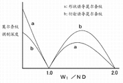
Fig. 2 A is the figure that is illustrated in according to the result who obtains by simulation Moire fringe modulation depth in the back barrier display unit of first embodiment, and Fig. 2 B is the figure that is illustrated in the result who obtains by simulation Moire fringe modulation depth in the preceding barrier display unit of prior art;
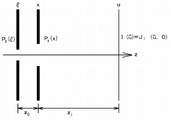
Fig. 3 A illustrates according to the illumination of local coherence theory to calculate the exemplary intensity map that obtains by calculating, and Fig. 3 B illustrates the concept map that image and light transmission department divide, and is used for the Diffraction Calculation that explanation comprises the shape that light transmission department divides in the shape of transmission-type display floater image and the disparity barrier;
Fig. 4 is illustrated in according to calculating employing W according to the illumination of local coherence theory in the back barrier display unit of first embodiment
1The intensity map that/ND obtains by calculating as parameter;
Fig. 5 is illustrated in the preceding barrier display unit of prior art to adopt W according to local coherence theory
1/ ND passes through to calculate the intensity map that obtains as the brightness calculation of parameter;
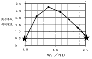
Fig. 6 A is the figure that is illustrated in according to the result who obtains by actual measurement Moire fringe modulation depth in the back barrier display unit of first embodiment, and Fig. 6 B is the figure that is illustrated in the preceding barrier display unit of prior art by the result of actual measurement Moire fringe modulation depth acquisition;
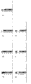
Fig. 7 is the partial schematic sectional view that is illustrated in according to constituting the liquid crystal indicator of disparity barrier in the display unit of first embodiment;
Fig. 8 A is the partial schematic sectional view of liquid crystal indicator, and it shows W in the liquid crystal indicator that constitutes disparity barrier in according to the display unit of first embodiment
1The running status of/ND=1.0, and Fig. 8 B is the partial schematic sectional view of liquid crystal indicator, it shows W in the liquid crystal indicator that constitutes disparity barrier in according to the display unit of first embodiment
1The running status of/ND=2.0;
Fig. 9 is the partial schematic sectional view that illustrates according to the liquid crystal indicator of the formation disparity barrier of second embodiment of the invention;
Figure 10 A is the partial schematic sectional view of liquid crystal indicator, and it shows W in the liquid crystal indicator that constitutes disparity barrier in according to the display unit of second embodiment
1The running status of/ND=1.0, and Figure 10 B is the partial schematic sectional view of liquid crystal indicator, it shows W in the liquid crystal indicator that constitutes disparity barrier in according to the display unit of second embodiment
1The running status of/ND=2.0;
Figure 11 A is the partial schematic sectional view that illustrates according to the liquid crystal indicator of the formation disparity barrier of third embodiment of the invention, and Figure 11 B is the partial schematic sectional view of liquid crystal indicator, and it shows the running status (W wherein of the liquid crystal indicator that constitutes disparity barrier
1/ ND=1.0);
Figure 12 A is the partial schematic sectional view that constitutes the liquid crystal indicator of disparity barrier in according to the modification of the display unit of the 3rd embodiment, and Figure 12 B is the partial schematic sectional view of liquid crystal indicator, and it shows the running status (W wherein of the liquid crystal indicator that constitutes disparity barrier
1/ ND=2.0);
Figure 13 is the perspective schematic view that illustrates according to the virtual decomposing state of the display unit of fourth embodiment of the invention;
Figure 14 is the schematic diagram that is illustrated in according to the relation that arranges between transmission-type display floater and the disparity barrier in the display unit of the 4th embodiment;
Figure 15 is the perspective schematic view that illustrates according to the virtual decomposing state of the modification of the display unit of the 4th embodiment;
Figure 16 is the partial schematic sectional view of display unit, is used for explanation in the relation that arranges according to display unit transmission-type display floater, disparity barrier and the planar illuminating device of first embodiment;
Figure 17 is the schematic diagram of the relation that arranges of viewpoint D1, D2, D3 and D4, transmission-type display floater, disparity barrier and planar illuminating device in the explanation viewing areas shown in Figure 1;
The schematic diagram of Figure 18 condition that to be explanation can propagate towards the viewpoint D1 in middle viewing areas, D2, D3 and D4 from the light of pixel;
The schematic diagram of Figure 19 condition that to be explanation can propagate towards the viewpoint D1 in left viewing areas, D2, D3 and D4 from the light of pixel;
Figure 20 is the schematic diagram that viewpoint D1, D2, D3 and the D4 of explanation in middle viewing areas watches image;
Figure 21 is the schematic diagram that viewpoint D1, D2, D3 and the D4 of explanation in left viewing areas watches image;
Figure 22 is the schematic diagram that viewpoint D1, D2, D3 and the D4 of explanation in right viewing areas watches image;
Figure 23 A and 23B are the schematic diagrames that the relation that arranges between transmission-type display floater and the disparity barrier is shown, and are used for explanation and do not produce the fact that shape is induced Moire fringe in the display unit according to the embodiment of the invention;
Figure 24 A and 24B are the schematic diagrames that the relation that arranges between transmission-type display floater and the disparity barrier is shown, and are used for explanation and produce the reason that shape is induced Moire fringe in the display unit of prior art; And
Figure 25 is illustrated in the photo that how to produce Moire fringe in the display unit of prior art.
Embodiment
Those skilled in the art should be understood that, in the scope of claims and equivalent thereof, according to design needs and other factors, can carry out various modifications, combination, part combination and replacement.
1. display unit of the present invention, general remark of the present invention
2. first embodiment (display unit of the present invention)
3. second embodiment (modification of first embodiment)
4. the 3rd embodiment (another modification of first embodiment)
5. the 4th embodiment (another modification of first embodiment) and other
[display unit of the present invention, general remark of the present invention]
In the display unit according to the embodiment of the invention, disparity barrier for example can provide light transmission department branch (opening) to make by the known materials at plate, sheet or form membrane.In addition, such disparity barrier can be by known method manufacturing, and these known methods are for for example, the combination of photoetching and etching technique; Various printing processes comprise silk screen printing, ink jet printing and metal mask print process; Coating method (galvanoplastic or electroless plating method); And peel off method.As selection, disparity barrier preferably is made of liquid crystal indicator, because it allows to show solid or 3-D view and two dimensional image.In other words, in the display unit according to the embodiment of the invention, disparity barrier preferably is made of liquid crystal indicator, and this liquid crystal indicator comprises at least:
First substrate,
First electrode forms and is patterned at first substrate,
Second substrate is arranged on the opposite side of first substrate,
Second electrode is formed on second substrate with relative with first electrode, and
Liquid crystal layer is folded between first substrate and second substrate.
In addition, therefore to the beholder that watches display unit not directly not as seen the disparity barrier of being made up of liquid crystal indicator and need not consider chromatic dispersion (chromatic dispersion) etc. in the substrate of formation liquid crystal indicator.
When disparity barrier is made up of liquid crystal indicator, constitute first electrode of light shield part along the width W D of first direction
21Can be less than the width W of light shield part along first direction
2Particularly, for example, this can be exemplified as follows:
1μm≤W
2-WD
21≤15μm
In addition, in the case, constitute first electrode of light transmission department branch along the width W D of first direction
11Can be less than the width W of light transmission department branch along first direction
1Particularly, for example, this can be exemplified as follows:
1μm≤W
1-WD
11≤15μm
In addition, when the disparity barrier that comprises these preferable configuration was made up of liquid crystal indicator, light transmission department divided the width W along first direction
1Can be configured to be transformed into according to the voltage status that imposes on first electrode and second electrode any one of following two conditions:
0.95×ND≤W
1≤1.05×ND
1.9×ND≤W
1≤2.1×ND
The width W that light transmission department divides
1Such conversion can enough improve on the transmission-type display floater brightness that shows image.In addition, in the case, when not having voltage to impose on first electrode and second electrode, the liquid crystal layer that constitutes the liquid crystal indicator of disparity barrier can be can make the light transmission by the state (Chang Bai) of this layer or can be and can not make the light transmission by the state (normal black) of this layer.
As selection, under the situation that disparity barrier is made up of liquid crystal indicator, the zone of the formation light shield part of liquid crystal indicator can provide formation first electrode thereon, and the zone of the formation transmissive portion of liquid crystal indicator can not provide first electrode.In addition, in the case, when not having voltage to impose on first electrode and second electrode, the liquid crystal layer that constitutes the liquid crystal indicator of disparity barrier preferably is in and can makes the light transmission by the state (Chang Bai) of this layer.
As selection, under the situation that disparity barrier is made up of liquid crystal indicator, the zone of the formation light shield of liquid crystal indicator part can provide formation first electrode thereon.In addition, the light transmission department branch provides on it zone that forms first electrode and the zone that does not form first electrode, and these zones are along first direction and put.Constitute first electrode of light transmission department branch along the width W D of first direction
11Can be less than the width W of light transmission department branch along first direction
1Particularly, for example, this can be exemplified as follows:
1μm≤W
1-WD
11≤15μm
In the case, when not having voltage to impose on first electrode and second electrode, the liquid crystal layer that constitutes the liquid crystal indicator of disparity barrier preferably is in and can makes the light transmission by the state (Chang Bai) of this layer.In addition, when the disparity barrier that comprises this preferable configuration was made up of liquid crystal indicator, light transmission department divided the width W along first direction
1Can be configured to be transformed into according to the voltage status that imposes on first electrode and second electrode any one of following two conditions:
0.95×ND≤W
1≤1.05×ND
1.9×ND≤W
1≤2.1×ND
Width W
1This conversion can enough improve on the transmission-type display floater brightness that shows image.
When comprising that the disparity barrier of so different preferable configuration is made up of liquid crystal indicator as mentioned above, the haze value of transmission-type display floater (haze value) is preferably 15% or littler.Haze value is used for adopting integrating sphere light transmission measurement mechanism to measure diffused transmission rate (diffuse transmittance) and all-optical transmittance (total light transmittance), and adopts the ratio of diffused transmission rate and all-optical transmittance to carry out assessment.The detail of haze value for example can be referring to JIS K7136:2000.In order to obtain the haze value of aforesaid transmission-type display floater, for example, the hyaline membrane with such haze value can join the transmission-type display floater to beholder's facing surfaces.As selection, for example, haze value can be controlled like this, makes the rough surface of polaroid, and the bulk material that perhaps will have different refractivity is dispersed in the polaroid material.If haze value is very high, then the light from the transmission-type display floater can be scattered when it leads viewing areas, and have the image of low directivity can be usually by visual identity.
In addition, in the display unit according to the embodiment of the invention that comprises above-mentioned various preferable shape and structure, the light transmission department branch of disparity barrier and light shield part can be configured to be parallel to the direction extension of second direction, and as selection, the angle θ that forms between the axle of disparity barrier and the second direction can be acute angle.Particularly, when pel array be ND along the pitch of second direction
2The time, if angle θ satisfies following equation,
θ=tan
-1(ND
2/ND)
Position relation between then the light transmission department of each pixel and the disparity barrier relative with each pixel the divides axle along disparity barrier usually is constant, therefore can reduce crosstalking of producing when showing stereo-picture, and realize high-quality stereo display.As selection, the light transmission department that constitutes disparity barrier divides the axle that can be configured to along disparity barrier to be arranged to straight line.As selection, the light transmission department that constitutes disparity barrier divides the axle that can be configured to along disparity barrier to be arranged to step-wise manner.
In the display unit according to the embodiment of the invention that comprises above-mentioned various preferable shape and structure (jointly abbreviating " display unit of the present invention etc. " hereinafter as), the transmission-type display floater for example can be made up of display panels.The structure of display panels, structure or driving mechanism etc. are not particularly limited.The transmission-type display floater can be monochrome or color monitor.Moreover the transmission-type display floater can be simple matrix and drives type or driven with active matrix type.In addition, in each embodiment that describes after a while, the active matrix drive-type display panels is as the transmission-type display floater.Display panels for example be configured to comprise the front panel that provides first transparency electrode, provide the rear board of second transparency electrode and be arranged on front panel and rear board between liquid crystal material.In addition, the example of the transmission-type display floater in display unit of the present invention etc. also comprises so-called half transmitting display panels, and wherein each pixel provides reflector space and regional transmission.
More specifically, front panel for example is made up of first substrate, first transparency electrode and light polarizing film, first substrate is by the glass substrate manufacturing, first transparency electrode (is also referred to as common electrode, for example by the ITO(indium tin oxide) make) be formed on the inner surface of first substrate, light polarizing film is formed on the outer surface of first substrate.In addition, in color liquid crystal display panel, front panel provides colour filter in the inner surface of first substrate, the coated coating of being made by acrylic resin or epoxy resin of this colour filter, and first transparency electrode is formed on the coating.Oriented layer is formed on first transparency electrode.The example that pattern is set of colour filter can comprise triangular array, bar shaped array, diagonal array and rectangular array.
On the other hand, more specifically, rear board for example is made up of second substrate, switch element, second transparency electrode and light polarizing film, second substrate is made by glass substrate, switch element is formed on the inner surface of second substrate, conductive /non-conductive is controlled by switch element in second transparency electrode (be also referred to as pixel electrode, and for example made by ITO), and light polarizing film is provided on the outer surface of second substrate.Oriented layer is formed on the whole surface that comprises second transparency electrode.The various parts and the liquid crystal material that constitute these light transmissive liquid crystal display panels can be made up of known parts or material.In addition, the example of switch element can comprise such as the three-terminal element of thin-film transistor (TFT) and such as the MIM(metal-insulator-metal) two-terminal element of element, varistor element or diode.
In addition, in color liquid crystal display panel, the zone that comprises liquid crystal cells is the overlapping region between first transparency electrode and second transparency electrode, and it is corresponding to a sub-pixel.Constitute colour filter that the sub-pixel that glows of each pixel passes through by relevant range and red light transmission in conjunction with forming.The green light sub-pixel is formed by the combination of the colour filter that relevant range and green light transmission are passed through.The blue light-emitting sub-pixel is formed by the combination of the colour filter that relevant range and blue light transmission are passed through.Rubescent, green and blue photons pixel arrange pattern and above-mentioned colour filter that pattern is set is consistent.The sub-pixel of one or more types with the formation group (for example can further add to this sub-pixel of three types, increase the sub-pixel that emits white light to improve the group of brightness, increase the sub-pixel send out complementary coloured light with the group of acquisition expanded color gamut, increase the sub-pixel of jaundice light to obtain the group of expanded color gamut, increase the sub-pixel of jaundice light or bluish-green coloured light to obtain the group of expanded color gamut).In addition, in these structures, each sub-pixel is corresponding to " pixel " in the transmission-type display floater of display unit of the present invention etc.
When the quantity M * N of the pixel that is set to two-dimensional matrix be defined as (M, in the time of N), several resolution that image shows, VGA(640 for example, 480), S-VGA(800,600), XGA(1024,768), APRC(1152,900), S-XGA(1280,1024), U-XGA(1600,1200), HD-TV(1920,1080) and Q-XGA(2048,1536), (1920,1035), (720,480) and (1280,960) can be exemplified as (M, value N).Yet it is not limited to these values.
In addition, constitute identical or similar that structure and the structure of the liquid crystal indicator of disparity barrier can be with the display panels that constitutes the transmission-type display floater, except the structure or structure of pixel and sub-pixel.Yet, can advantageously have the function of so-called optical shutter because constitute the liquid crystal indicator of disparity barrier, so it can comprise that for the common liquid crystal indicator that shows image be necessary switch element or colour filter, therefore and can realize structure and the structure simplified therefore having guaranteed high reliability and long-life.In addition, it can form black matrix, has therefore simplified the overall craft of making liquid-crystal apparatus.First substrate of transmission-type display floater and liquid crystal indicator can be toward each other.Second substrate of transmission-type display floater and liquid crystal indicator can be toward each other.
Planar illuminating device in the display unit of the present invention etc. (backlight) can be made up of known planar illuminating device.In other words, planar illuminating device can be the full run-down type planar light source device, perhaps can be edge-light type (being also referred to as side light type) planar light source device.The full run-down type planar light source device for example comprises light source, reflector element and diffuser plate, the light source setting in the enclosure, reflector element is arranged on the part of the shell under the light source and is configured to upwards reflection from the light of light source emission, and diffuser plate is attached to the opening of the shell that forms on the light source and is configured to spread and by from the light of light source emission and from the light of reflector element reflection.On the other hand, the edge-light type planar light source device for example comprises optical plate and the light source that is arranged on the optical plate side.In addition, reflector element is arranged under the optical plate, and diffusion sheet or prismatic lens are arranged on the optical plate.Light source for example is made up of cold-cathode fluorescence lamp and is launched white light.As selection, for example, light source is by forming such as the light-emitting component of LED or semiconductor Laser device.
The driver element that drives planar illuminating device or transmission-type display floater for example can be by various circuit, and for example, image signal processing unit, timing control unit, data driver, gate drivers and light source control unit are formed.They can be by adopting known compositions such as circuit element.
Display unit of the present invention can show stereo-picture.Stereo-picture and two dimensional image can show according to structure and the structure of display unit of the present invention.As selection, display unit of the present invention can show the image of differently being watched by watching display unit from different angles.In the case, the view data that be transferred to display unit can be and shows the view data that stereo-picture is required or show the required view data of two dimensional image.
For example, by in display unit, providing change over switch and by allowing the beholder to operate change over switch, can carrying out the width W of convert light transmissive portion
1As selection, the width W that the image signal processing unit in the display unit can be configured to analyze the view data that will show and automatically perform the convert light transmissive portion
1Be important but image brightness is not under the very important situation in picture quality, the width W that light transmission department divides
1To be very little (W1=α ND).Be important but picture quality is not under the very important situation in image brightness, the width W that light transmission department divides
1With very big (W
1=2 α ND).Like this, under the width W 1 that light transmission department divides is very big situation, when the stereo-picture with strong stereoscopic vision is presented on the transmission-type display floater, the considerable superimposed images that are seen as of stereo-picture, perhaps the meeting generation is image blurring in stereo-picture, although it is slight.Therefore, be presented on the transmission-type display floater if image signal processing unit is determined the stereo-picture with strong stereoscopic vision, then image signal processing unit can be carried out conversion so that the width W that light transmission department divides
1Less, on the contrary, if determining the stereo-picture with weak stereoscopic vision, image signal processing unit is presented on the transmission-type display floater, and then image signal processing unit can be carried out conversion so that the width W 1 that light transmission department divides is bigger.These processes are carried out based on the analysis of the depth map in the view data that will show (depth map) with from analyzing the result who obtains.In the case, because the frequent transitions of the width W 1 that light transmission department divides, the remarkable possibility that changes of brightness that may have the transmission-type display floater, but the possible remarkable change of transmission-type display floater brightness can be controlled by the luminous quantity (moving by the light source in the control planar illuminating device) of suitably adjusting planar illuminating device.
[first embodiment]
First embodiment relates to the display unit of the present invention that adopts so-called back barrier pattern.Fig. 1 is the perspective view that schematically shows according to the virtual decomposing state of the display unit of first embodiment.Figure 16 is the partial schematic diagram of display unit, is used for explanation according to the relation that arranges of display unit transmission-type display floater 10, disparity barrier 130 and the planar illuminating device 20 of first embodiment.
As shown in Figure 1, the display unit of first embodiment comprises transmission-type display floater 10, planar illuminating device 20 and disparity barrier 130.Transmission-type display floater 10 is configured to make pixel 12 at first direction (in this embodiment, particularly, level or directions X) with the second direction different with first direction (in this embodiment, particularly, vertical or Y-direction) on be arranged to the two-dimensional matrix form.Planar illuminating device 20 is from its back illumination transmission-type display floater 10.Disparity barrier 30 is arranged between transmission-type display floater 10 and the planar illuminating device 20, and the image that is configured to show on the transmission-type display floater 10 is divided into the image for a plurality of viewpoints.
Transmission-type display floater 10 is made up of the active matrix color liquid crystal display panel.In the viewing area 11 of transmission-type display floater 10, M pixel and N pixel 12 are separately positioned on first direction (horizontal direction, directions X) and the second direction (vertical direction, Y-direction).M is capable, and (M) pixel 12 in is represented by " pixel 12m " for m=1 wherein, 2....Each pixel 12 has the luminous sub-pixel of red, green and blue.Transmission-type display floater 10 be included in the viewing areas side front panel, the rear board of disparity barrier side and be arranged on front panel and rear board between liquid crystal material etc.For the purpose of illustrated convenience, in Fig. 1,13 and 15, transmission-type display floater 10 is depicted as single panel.
The display panels that constitutes transmission-type display floater 10 comprise front panel with first transparency electrode, have the rear board of second transparency electrode and be provided at front panel and rear board between liquid crystal material.Front panel comprises first substrate made by glass substrate, be formed on first transparency electrode on the first substrate inner surface and be formed on light polarizing film on first outer surface of substrate.In addition, the colour filter that is coated with the coating of being made by acrylic resin or epoxy resin is provided in the inner surface of first substrate, and first transparency electrode is formed on the coating.Oriented layer is formed on first transparency electrode.On the other hand, second substrate that rear board is made by glass substrate, be formed on switch element, second transparency electrode on the second substrate inner surface and the light polarizing film that is formed on second outer surface of substrate is formed, wherein control conduction in second transparency electrode/non-conductive by switch element.Oriented layer is formed on the whole surface that comprises second transparency electrode.The zone that comprises liquid crystal cells is the overlapping region between first transparency electrode and second transparency electrode, and it is corresponding to a sub-pixel.
Disparity barrier 130 and transmission-type display floater 10 are set to the predetermined gap (Z with therebetween
1) toward each other.Particularly, in the display unit of first embodiment, transmission-type display floater 10 and disparity barrier 130 form with the gap separate.This gap can be filled with air or vacuum layer, perhaps can be occupied by the transparent component (not shown).Consider the refractive index of the material of filling the gap, optical path length can be Z
1In addition, disparity barrier 130 comprises that a plurality of light transmission departments divide 131 and light shield part 132, they in the mode that replaces along first direction (horizontal direction, directions X) and put.Light transmission department divide 131 and light shield part 132 extend along the axle AX that is parallel to second direction (vertical direction, Y-direction), perhaps form acute angle with second direction (vertical direction, Y-direction).In addition, in first embodiment, light transmission department divide 131 and light shield part 132 extend to and be parallel to second direction (vertical direction, Y-direction).In other words, the axle AX of disparity barrier 130 is parallel to second direction (vertical direction, Y-direction).A plurality of (P) light transmission department branch (opening) 131 is arranged on the first direction (horizontal direction, directions X).P capable (wherein, p=1,2 ..., P) light transmission department in divides 131 to divide 131 by light transmission department
pExpression.After a while will be with reference to Figure 17,18 and 19 relations of describing between " P " and above-mentioned " M ".
In addition, distance between disparity barrier 130 and the transmission-type display floater 10, the array pitch of pixel 12 on directions X are (hereinafter, usually abbreviate " pixel pitch " as) and light transmission department divide 131 pitches (abbreviating hereinafter, " light transmission department branch pitch " usually as) on directions X to be set to satisfy the condition that in by the predefined viewing areas of the specification of display unit, can watch preferred stereo-picture.This condition will be discussed in more detail below.
In first embodiment, will show on the explanation display unit that the number of views of image is assumed to be at viewing areas WA shown in Figure 1
L, WA
CAnd WA
RIn the situation of four viewpoint D1, D2, D3 and D4 separately, yet this is not limited thereto.The quantity of viewing areas and number of views can suitably be set according to the design of display unit.
Figure 17 shows for explanation viewing areas WA shown in Figure 1
L, WA
CAnd WA
RIn the schematic diagram of the relation that arranges of each viewpoint D1, D2, D3 and D4, transmission-type display floater 10, disparity barrier 130 and planar illuminating device 20.In addition, Figure 18 is for illustrating that the light from pixel 12 is directed to middle viewing areas WA
CIn the schematic diagram of condition of viewpoint D1, D2, D3 and D4.And Figure 19 is for illustrating that the light from pixel 12 is directed to left viewing areas WA
LIn the schematic diagram of condition of viewpoint D1, D2, D3 and D4.
For the purpose of the facility that illustrates, suppose that the odd number light transmission department divides 131 to be arranged on the directions X, and the light transmission department of p in capable divides 131
pBe positioned at light transmission department and divide 131
1 Divide 131 with light transmission department
PBetween the centre.Moreover, the pixel 12 during m is capable
mWith the pixel 12 in (m+1) row
M+1Between border and viewing areas WA
CIn viewpoint D2 and the mid point between viewpoint D3 hypothesis be positioned at and extend through light transmission department along the Z direction and divide 131
pThe virtual line at center.(unit: mm) expression, and light transmission department divides pitch by " RD " (unit: mm) expression to pixel pitch by " ND ".In addition, light transmission department divide 131 and transmission-type display floater 10 between distance by " Z
1" (unit: mm) expression, and transmission-type display floater 10 and viewing areas WA
L, WA
C, WA
RBetween distance by " Z
2" (unit: mm) expression.Moreover, viewing areas WA
L, WA
C, WA
RIn adjacent viewpoint between distance by " DP " (unit: mm) expression.
When light transmission department divides 131 width by W
1The width of expression and light shield part 132 is by W
2During expression, light transmission department branch pitch RD and light transmission department divide 131 width W
1Width W with light shield part 132
2Between set up relation of plane down:
RD=W
1+W
2
To consider to divide 131 from light transmission department
pBy pixel 12
M-1, 12
m, 12
M+1With 12
M+2Light be directed in the middle of viewing areas WA
CIn the condition of viewpoint D1, D2, D3 and D4.For convenience of explanation, describe to concentrate on by light transmission department and divide on the track of light at 131 centers, and the hypothesis light transmission department divides 131 width W
1Fully little.Divide 131 from extending through light transmission department along the Z direction
pThe virtual line at center is to pixel 12
M+2The distance at center is by X
1Represent, and divide 131 from extending through light transmission department along the Z direction
pThe virtual line at center is to middle viewing areas WA
CIn the distance of viewpoint D4 by X
2Expression.When light divides 131 from light transmission department
pBy pixel 12
M+2Advance to viewing areas WA
CViewpoint D4 the time, satisfied by (1) the given condition that establishes an equation down by geometric similarity relation:
Z
1/X
1=(Z
1+Z
2)/X
2 (1)
Wherein, X
1=1.5 * ND, and X
2Therefore=1.5 * DP passes through they substitution equations (1), and equation (1) can be expressed as following equation (1'):
Z
1/(1.5×ND)=(Z
1+Z
2)/(1.5×DP) (1')
Clearly visible geometrically, during equation (1') above satisfying, divide 131 from light transmission department
pTransmission is by pixel 12
M-1, 12
mWith 12
M+1Each light towards viewing areas WA
CIn viewpoint D1, D2 and D3 advance.
Next, will consider to divide 131 from light transmission department
P+1By pixel 12
M-1, 12
m, 12
M+1With 12
M+2Each light of transmission is towards left viewing areas WA
LIn viewpoint D1, D2, D3 and the D4 condition of advancing.
Divide 131 from extending through light transmission department along the Z direction
P+1The virtual line at center is to pixel 12
M+2The distance at center is by X
3Represent, and divide 131 from extending through light transmission department along the Z direction
P+1The virtual line at center is to left viewing areas WA
LIn the distance of viewpoint D4 by X
4Expression.When light divides 131 from light transmission department
P+1By pixel 12
M+2Advance to viewing areas WA
LIn viewpoint D4 the time, satisfied by the given condition of following equation (2) by geometric similarity relation:
Z
1/X
3=(Z
1+Z
2)/X
4 (2)
Wherein, X
3=RD-X
1=RD-1.5 * ND, and X
4Therefore=RD+2.5 * DP passes through they substitution equations (2), and equation (2) can be expressed as following equation (2'):
Z
1/(RD-1.5×ND)=(Z
1+Z
2)/(RD+2.5×DP) (2')
Clearly visible geometrically, during equation (2') above satisfying, divide 131 from light transmission department
P+1Transmission is by pixel 12
M-1, 12
mWith 12
M+1Each light towards viewing areas WA
LIn viewpoint D1, D2 and D3 propagate.
It should be noted that from light transmission department and divide 131
P-1Transmission is by pixel 12
M-1, 12
mWith 12
M+1Each light towards right viewing areas WA
RIn viewpoint D1, D2, D3 and the condition propagated of D4 identical when overturning about the Z axle with Figure 19, and so omit its explanation.
Be set to predetermined value apart from the value of Z2 and distance B P according to the specification of display unit.In addition, the value of pixel pitch ND is according to the structures shape of transmission-type display floater 10.For distance Z
1Dividing pitch RD with light transmission department, can be by equation (1') and (2') obtains in following equation (3) and (4):
Z
1=Z
2×ND/(DP-ND) (3)
RD=4×DP×ND/(DP-ND) (4)
In the above in the example of Miao Shuing, the value of light transmission department branch pitch RD is about four times of value of pixel pitch ND.Therefore, above-mentioned " M " and " P " has the M of relation ≈ P * 4.Be set at apart from Z1 and light transmission department branch pitch RD and satisfy above-mentioned condition, and the image of predetermined viewpoint can be at viewing areas WA
L, WA
CAnd WA
RIn each viewpoint D1, D2, D3 and D4 watch.For example, if the pixel pitch ND of transmission-type display floater 10 is 0.100mm, be 1500mm apart from Z2, and distance B P is 65.0mm, be 2.31mm apart from Z1 then, and light transmission department branch pitch RD be 0.400mm.
Figure 20 is at middle viewing areas WA for explanation
CIn viewpoint D1, D2, D3 and D4 watch the schematic diagram of image.Moreover Figure 21 is at left viewing areas WA for explanation
LIn viewpoint D1, D2, D3 and D4 watch the schematic diagram of image.In addition, Figure 22 is at right viewing areas WA for explanation
RIn viewpoint D1, D2, D3 and D4 watch the schematic diagram of image.
Shown in Figure 20,21 and 22, by pixel 12
1, 12
5, 12
9... the image that forms of pixel 12 in sight at viewpoint D1, and by pixel 12
2, 12
6, 12
10... the image that forms of pixel 12 see at viewpoint D2.In addition, by pixel 12
3, 12
7, 12
11... the image that forms of pixel 12 see at viewpoint D3, and by pixel 12
4, 12
8, 12
12... the image that forms of pixel 12 see at viewpoint D4.Therefore, the image that is used for first viewpoint adopts pixel 12
1, 12
5, 12
9... pixel 12 show that the image that is used for second viewpoint adopts pixel 12
2, 12
6, 12
10... pixel 12 show that the image that is used for the 3rd viewpoint adopts pixel 12
3, 12
7, 12
11... pixel 12 show that and the image that is used for the 4th viewpoint adopts pixel 12
4, 12
8, 12
12... pixel 12 show, thereby but beholder's recognition image is stereo-picture.
Although the viewpoint number is " 4 " in the superincumbent explanation, the viewpoint number can suitably be selected according to the specification of display unit.For example, can adopt the structure with viewpoint number " 2 " or the structure with viewpoint number " 6 ".In the case, but the structure appropriate change of disparity barrier 30 grades.This is similar to other embodiment, will describe after a while.
In the display unit of first embodiment, induce Moire fringe and shape to induce Moire fringe in order to reduce diffraction, satisfy following conditions:
0.95×ND≤W
1≤1.05×ND
For example,
W
1=1.0×ND
As selection, satisfy following conditions:
1.9×ND≤W
1≤2.1×ND
For example,
W
1=2.0×ND
In addition, very important and its image brightness is not under the very important situation in the picture quality of display unit, can adopt the form that satisfies following condition:
0.95×ND≤W
1≤1.05×ND
On the contrary, its picture quality is not under the very important situation in that the image brightness of display unit is very important, can adopt the form that satisfies following condition:
1.9×ND≤W
1≤2.1×ND
In addition, satisfying under the situation of following condition,
1.9×ND≤W
1≤2.1×ND
When the stereo-picture with strong stereoscopic vision was presented on the display unit, stereo-picture can be watched and be superimposed images, and perhaps the meeting generation is image blurring in stereo-picture, although very slight.
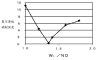
Fig. 2 A shows the result who obtains by simulation Moire fringe modulation depth according in the back barrier display unit of first embodiment, and Fig. 2 B shows the result that simulation Moire fringe modulation depth obtains in the preceding barrier display unit of prior art.In addition, in Fig. 2 A and 2B, transverse axis represent when pel array along the pitch ND of first direction during for " 1 ", light transmission department divides the width W along first direction
1Value.In Fig. 2 A and 2B, the Moire fringe modulation depth that " a " expression induces Moire fringe to cause owing to shape, and " b " expression is because the Moire fringe modulation depth that diffraction induces Moire fringe to cause.In addition, the longitudinal axis is represented the Moire fringe modulation depth.The Moire fringe modulation depth can be expressed as the variation (i.e. (maximum brightness value-minimum luminance value)/(maximum brightness value+minimum luminance value)) of the brightness that is caused by the Moire fringe on the display surface of display unit.
When simulation Moire fringe modulation depth, calculate according to the illumination of the partial coherence theory of considering spatial coherence, carry out and comprise in the transmission-type display floater Diffraction Calculation of light transmission department branch shape in the primitive shape and disparity barrier.
When the direction perpendicular to the viewing area 11 of transmission-type display floater 10 is axis of optical propagation z, be evaluated at distribute in the face of light in diffraction how to change along axis of optical propagation z.On computation model, by separating variable change is only limited to an axle.Shown in the concept map of Fig. 3 B, rectangular aperture P
0(ξ) with rectangular aperture P
x(x) be separately positioned on ξ axle and the x axle their gap separation Z
0(=Z
1).Under the situation of barrier pattern after the employing, P
0(ξ) corresponding to the light transmission department branch of disparity barrier, and P
x(x) corresponding to the pixel in the transmission-type display floater.On the other hand, before employing under the situation of Barrier method, P
0(ξ) corresponding to the pixel in the transmission-type display floater, and P
x(x) corresponding to the light transmission department branch of disparity barrier.In addition, the u axle is arranged on as image-watching position (projection screen face) apart from x axle z
iOn the position of distance.The target of calculating is the optical profile that obtains on the u axle.Because this target is the optical profile that obtains the image-watching position, be called the projection screen face for convenience of the plane perpendicular to the z axle with the image-watching position.
Suppose to exist equivalent light source, wherein have central wavelength lambda (in the equation below (A), λ by
 Expression, it has the last horizontal line "-" on symbol " λ ") the opening P of distribution of light sources on the ξ axle of spectral distribution
0(ξ), and the spatial coherence of light source is μ (Δ ξ).By the calculating according to the partial coherence theory, the intensity I on the screen (u) can be by adopting mutual intensity (joint intensity) J on the screen
i(u, 0) is expressed as following equation (A).It should be noted that down in establish an equation (A) u by
Expression, it has the last horizontal line "-" on symbol " λ ") the opening P of distribution of light sources on the ξ axle of spectral distribution
0(ξ), and the spatial coherence of light source is μ (Δ ξ).By the calculating according to the partial coherence theory, the intensity I on the screen (u) can be by adopting mutual intensity (joint intensity) J on the screen
i(u, 0) is expressed as following equation (A).It should be noted that down in establish an equation (A) u by
 Expression, it has horizontal line "-" on symbol " u ".
In equation (A), I
0The expression constant represents light intensity.When mutual intensity is defined in separately ξ axle, x axle and the u axial plane according to local coherence theory, on " ξ ", has the variable of last horizontal line "-"
 The variable that on " x ", has last horizontal line "-"
 And variable
 Each all represent separately the independent center of two
 variable ξ 1 and ξ 2, x1 and x2, u1 and u2.Δ ξ and Δ x represent the difference separately of these two variablees.Can calculate from the light in specific pixel and disparity barrier zone and distribute, and according to equation (A), can accurately estimate the light intensity of the pixel that the beholder that is positioned at ad-hoc location watches.
Radiation profiles under all whole conductings of pixel situation of (complete white the demonstration) can adopt equation (A) to obtain, with by the optical profile of calculating from the photometry of each pixel in the projection screen face.Be each pixel definition P
(0, n)(ξ), calculate the optical profile I that is produced by them
n(u) (u in establish an equation down (B) by
 Expression, it has last horizontal line "-" on symbol " u ").Because full white illumination is the summation of all pixel illumination, so can set up following equation (B):
Fig. 3 A shows the Practical Calculation example according to equation (B).Calculating is based on each Luminance Distribution I in seven pixels
n(n) (Fig. 3 A shows based on each Luminance Distribution " A " in four pixels) obtains the total brightness I by " B " expression among Fig. 3 A then
Total(u).When attentiveness concentrates on the Luminance Distribution (optical profile) of total brightness, on total brightness, in the cycle in the overlapping cycle that is higher than each pixel brightness irregularities can take place, and have slight dependence of angle from an angle of radiation distribution character of fixing a point (certain gap) of the viewing area 11 in the transmission-type display floater 10.It should be noted that in Fig. 3 A transverse axis is that (unit: mm), and the longitudinal axis is to work as I for distance on the u axle
0Relative brightness value when being set to " 1.0 ".This irregularity in brightness (in Fig. 3 A, 4 and 5 figure, seeing the zigzag part (for example, " B " among Fig. 3 A) at the shape top that is similar to trapezium) is corresponding to the Moire fringe modulation depth.
Figure 4 and 5 show the sample calculation of the Moire fringe modulation of considering diffraction.It should be noted that Fig. 4 shows the result who obtains by Moire fringe modulation calculating in according to the back barrier display unit of first embodiment, and Fig. 5 shows the result who obtains by Moire fringe modulation calculating in the preceding barrier display unit of prior art.In Fig. 4, " A " represents W
1The situation of/ND=0.9, " B " represents W
1The situation of/ND=1.0, " C " represents W
1The situation of/ND=1.1, " D " represents W
1The situation of/ND=1.2, " E " represents W
1The situation of/ND=1.3, " F " represents W
1The situation of/ND=1.4, " G " represents W
1The situation of/ND=1.5, " H " represents W
1The situation of/ND=1.6, " I " represents W
1The situation of/ND=1.7, " J " represents W
1The situation of/ND=1.8, " K " represents W
1The situation of/ND=2.0, and " L " expression W
1The situation of/ND=2.1.In addition, in Fig. 5, " A " represents W
1The situation of/ND=1.1, " B " represents W
1The situation of/ND=1.2, " C " represents W
1The situation of/ND=1.3, " D " represents W
1The situation of/ND=1.4, " E " represents W
1The situation of/ND=1.5, " F " represents W
1The situation of/ND=1.6, and " G " expression W
1The situation of/ND=1.7.In Figure 4 and 5, transverse axis is the distance on the u axle, and scale is separated with one meter interval.Moreover the longitudinal axis is to work as I
0Relative brightness when being set to " 1.0 ".In addition, use following parameter in the calculating.
[the back barrier display unit of first embodiment shown in Figure 4]
Rectangular aperture P
0Width (ξ): 176 μ m
Rectangular aperture P
0Pitch (ξ): 176 μ m
Spatial coherence length Δ μ: 0.03 μ m
P
x(x) width: 130 μ m
Central wavelength lambda
0: 500nm
Gap z
0: 17.8mm
z
i:4m
[of the prior art preceding barrier display unit shown in Figure 5]
Rectangular aperture P
0Width (ξ): 130 μ m
Rectangular aperture P
0Pitch (ξ): 176 μ m
Spatial coherence length Δ μ: 0.03 μ m
P
x(x) width: 176 μ m
Central wavelength lambda
0: 500nm
Gap z
0: 17.8mm
z
i:4m
It should be noted that Δ μ is so-called spatial coherence length, the coherence between it represents at 2 remains on distance in a lateral direction.As example, expression point-to-point transmission coherence's coherent function μ (Δ ξ) can adopt that the distance, delta ξ between 2 is expressed as μ (Δ ξ)=exp[-Δ ξ on the light source
2/ (2 Δ μ
2)]/(2 π)
1/2This function has a constant value (1/(2 π) of determining when Δ ξ very little (distance that is point-to-point transmission is short significantly)
1/2), and this value just reduces rapidly after Δ ξ is greater than Δ μ.Therefore, this function is typically used as representation space coherence's function.
Referring to Fig. 2 A, in the back barrier display unit of first embodiment, work as W
1When the value of/ND increases, induce Moire fringe and diffraction to induce the Moire fringe modulation depth of Moire fringe when this value is " 1 ", to become minimum based on shape, and the increase that when this value surpasses " 1 ", becomes, W worked as subsequently
1When the value of/ND reduces, and when being " 2 ", this value becomes minimum.On the other hand, in the preceding barrier display unit of prior art, work as W
1When the value of/ND increases, induce the Moire fringe modulation depth of Moire fringe to become minimum when this value is " 1 " based on shape, the increase that becomes when this value surpasses " 1 " when this value reduces, becomes minimum subsequently when this value is " 2 ".Yet, work as W
1When the value of/ND increases, induce the Moire fringe modulation depth of Moire fringe when this value is positioned between " 1 " and " 2 ", to become minimum based on diffraction, when this value surpasses this scope, become increase, and subsequently in addition this value during for " 2 " the Moire fringe modulation depth very big.In other words, in the display unit of first embodiment, at W
1When the value of/ND is " 1 " or " 2 ", can reduces shape and induce Moire fringe and diffraction to induce the generation of Moire fringe.But, in the display unit of prior art, work as W
1When the value of/ND is " 1 " or " 2 ", have been found that it can not reduce the generation that diffraction is induced Moire fringe, although can reduce the generation that shape is induced Moire fringe.
Fig. 6 A shows by making the width W of disparity barrier 130
1Different and in the back barrier display unit of first embodiment result by the complete white Moire fringe modulation depth acquisition that shows of actual measurement.Fig. 6 B shows the result who obtains by the complete white Moire fringe modulation depth that shows of actual measurement in the preceding barrier display unit of prior art.The result who obtains by simulation among the result who obtains by actual measurement Moire fringe modulation depth among Fig. 6 A and the 6B and Fig. 2 A and the 2B is consistent effectively, particularly by simulating the result of acquisition who induces the Moire fringe modulation depth of Moire fringe according to diffraction.In other words, suppose that strong diffraction induces Moire fringe to be created in the actual display unit.
By way of parenthesis, in the preceding barrier pattern shown in Fig. 6 B, at W
1Near the Moire fringe minimum/ND=1.4.Yet in the transmission-type display floater, Moire fringe can be created in W
1Near/the ND=1.4.For example, when the luminous component that adopts pixel wherein such as the MVA(multidomain vertical orientation) during the transmission-type display floater that changes in the halftoning of type, shape induces the intensity of Moire fringe to change over halftoning, and therefore produces Moire fringe.In the case, the W of Moire fringe minimum wherein
1The value of/ND changes according to tonal gradation, and the whole Moire fringes that therefore produce on the whole tonal gradation in the barrier pattern before the extremely difficult removal.Yet, in the back barrier pattern shown in Fig. 6 A, work as W
1/ ND=1.0 or W
1During/ND=2.0, W
1The value of/ND becomes integral multiple, so Moire fringe is not created in the multidomain vertical orientation such as MVA() in the transmission-type display floater of type, wherein the luminous component of pixel changes according to tonal gradation.From top description as can be known, irrelevant with the type of transmission-type display floater or halftoning display packing in the barrier pattern of back, can remove Moire fringe under the condition below:
W
1/ND=1.0
And
W
1/ND=2.0
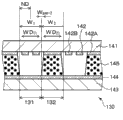
According to first embodiment, disparity barrier 130 comprises liquid crystal indicator 140.In other words, shown in the partial schematic sectional view of Fig. 7 A, 7B, 8A and 8B, in the display unit of first embodiment, disparity barrier 130 comprises at least:
The light transmission department of the pixel of transmission-type display floater 10 (sub-pixel) 12 and disparity barrier 130 divides the relation that arranges between 131 shown in Figure 23 A and 23B.
First patterned electrodes 142 by the transparent electrode material manufacturing extends on the second direction.On the other hand, be not patterned by second electrode 144 of transparent electrode material manufacturing and be so-called complete electrode.The structure of the liquid crystal indicator 140 of formation disparity barrier 130 is identical or similar with the display panels of formation transmission-type display floater 10 with structure, except the structure or structure of pixel and sub-pixel.In addition, switch element, colour filter or black matrix can be not included in this structure.
In constituting the liquid crystal indicator 140 of disparity barrier 130, light transmission department divide 131 and the group of light shield part 132 comprise first an electrode 142A who forms light shield part 132 and form light transmission department and divide two first electrode 142B of 131.In addition, divide 131 width W along first direction at light transmission department
1Be essentially pel array under the situation of the pitch ND of first direction a times (being called " first situation " for convenience's sake), light transmission department divides 131 to be made up of one of two first electrode 142B, and light shield part 132 is made up of another of first an electrode 142A and two first electrode 142B.On the other hand, divide 131 width W along first direction at light transmission department
1Be essentially pel array under the situation of the twice (being called " second situation " for convenience's sake) of the pitch ND of first direction, light transmission department divides 131 to be made up of two first electrode 142B, and light shield part 132 is made up of first an electrode 142A.Like this, form the first electrode 142A of light shield part 132 along the width W D of first direction
21Less than the width W of light shield part 132 along first direction
2Moreover, form light transmission department and divide 131 the first electrode 142B width W D along first direction
11Less than the width W of light transmission department branch along first direction
1Particularly, in first situation, the equation (seeing Fig. 8 A) below setting up:
W
2-WD
21=10μm
And
W
1-WD
11=10μm
Moreover, in second situation, the equation (seeing Fig. 8 B) below setting up:
W
2-WD
21=10μm
And
W
1-WD
11=10μm
In addition, the gap width W between the first electrode 142B and the first electrode 142B
Gap-1And first the gap width W between electrode 142A and the first electrode 142B
Gap-2Be set as follows respectively:
W
gap-1=10μm
And
W
gap-2=10μm
Light transmission department divides the width W along first direction
1Be transformed into down any one (the seeing Fig. 8 A and 8B) that establishes an equation according to the voltage status that imposes on first electrode 142 and second electrode 144:
W
1=1.0×ND
And
W
1=2.0×ND
The width W that light transmission department divides
1This conversion can enough increase the brightness that is presented at transmission-type display floater 10 epigraphs.When not having voltage to impose on first electrode 142 and second electrode 144, the liquid crystal layer 145 that constitutes the liquid crystal indicator 140 of disparity barrier 130 can be state (Chang Bai) that can be by this layer transmitted light or can be can not be by the state (often deceiving) of this layer transmitted light.In addition, two dimensional image can be presented in liquid crystal indicator 140 state as shown in Figure 7.
More specifically, as mentioned above, if the pixel pitch ND of transmission-type display floater 10 is 0.100mm, be 1500mm apart from Z2, and distance B P is 65.0mm, be 2.31mm apart from Z1 then, and light transmission department branch pitch RD be 0.400mm.In first situation, the equation below setting up:
W
1=0.100mm
And
W
2=0.300mm
As selection, in second situation, the equation below setting up:
W
1=0.200mm
And
W
2=0.200mm
Therefore, set up following equation:
W
11=0.090mm
And
W
21=0.190mm
And in first embodiment, the haze value of transmission-type display floater 10 is 4%.Particularly, wherein can be combined on the transmission-type display floater 10 at the particle spraying film thereon of carrying out roughening technology such as the surface of the hyaline membrane (not shown) of PET or TAC film or having a different refractivity.
According to the display unit of first embodiment, can show stereo-picture and two dimensional image, perhaps as selecting, when display unit is viewed from different angles, can show different images.According to the display unit of first embodiment, disparity barrier is arranged on the rear surface of transmission-type display floater.And light transmission department divides the width W along first direction
1Be essentially pel array along one times or the twice of the pitch ND of first direction, so it can reduce and produces diffraction and induce Moire fringe and shape to induce Moire fringe.
[second embodiment]
Second embodiment is the modification of first embodiment.According to second embodiment, shown in Fig. 9,10A and 10B, they show the partial schematic sectional view of the liquid crystal indicator 240 that constitutes disparity barrier 230, and the first electrode 242A is formed on the regional 240B of formation light shield part 232 of liquid crystal indicator.In addition, light transmission department divides 231 to be configured to comprise the regional 231B that forms the first electrode 242B on it and the regional 231A that does not form first electrode on it.These two regional 231B, 231A are along first direction and put.In addition, divide 231 width W along first direction at light transmission department
1Be essentially pel array under one times the situation (first situation) of the pitch ND of first direction, light transmission department divides 231 to be made up of the regional 231A that does not form first electrode on it, and light shield part 232 is made up of the first electrode 242A and the first electrode 242B.On the other hand, divide 231 width W along first direction at light transmission department
1Be essentially pel array under the situation (second situation) of the twice of the pitch ND of first direction, light transmission department divides 231 to be made up of the regional 231A that does not form first electrode on the regional 231B that forms the first electrode 242B on it and its, and light shield part 232 is made up of the first electrode 242B.It should be noted that constituting light transmission department divides 231 the first electrode 242B width W D along first direction
11Divide 231 width W along first direction less than light transmission department
1Particularly, in first situation, the equation (seeing Figure 10 A) below setting up:
W
1-WD
11=10μm
Moreover, in second situation, the equation (seeing Figure 10 B) below setting up:
W
1-WD
11=10μm
Gap width W between the first electrode 242A and the first electrode 242B
Gap-2Be basically the same as those in the first embodiment.When not having voltage to impose on first electrode 242 and second electrode 244, the liquid crystal layer 245 in the liquid crystal indicator 240 of formation disparity barrier 230 is can be by the state (Chang Bai) of this layer transmitted light.According to second embodiment, light transmission department divides 131 width W along first direction
1Be transformed into down any one (the seeing Figure 10 A and 10B) that establishes an equation according to the voltage status that imposes on first electrode 242 and second electrode 244:
W
1=1.0×ND
And
W
1=2.0×ND
This width W
1Conversion can enough increase on the transmission-type display floater 10 brightness of the image that shows.In addition, two dimensional image can be presented under the state of liquid crystal indicator shown in Figure 9 240.
[the 3rd embodiment]
The 3rd embodiment also is the modification of first embodiment.In first and second embodiment, light transmission department divides 331 W along first direction
1Be variable.On the other hand, in the 3rd embodiment, light transmission department divides 331 W along first direction
1Fix.Particularly, display unit according to the 3rd embodiment, shown in Figure 11 A and 12A, they show the partial schematic sectional view of the liquid crystal indicator 340 that constitutes disparity barrier 330, first electrode 342 is formed on the regional 340B of formation light shield part 332 of liquid crystal indicator, and first electrode formation light transmission department that is not formed on liquid crystal indicator 340 divides on 331 the regional 340A.When not having voltage to impose on first electrode 342 and second electrode 344, the liquid crystal layer 345 in the liquid crystal indicator of formation disparity barrier 330 is can be by the state (Chang Bai) of this layer transmitted light.Shown in Figure 11 B, light transmission department divides 331 width to be set to 0.100mm, and the gap width between first electrode 342 and first electrode 342 is set to 0.110mm, the equation below therefore obtaining:
W
1=1.0×ND
On the other hand, shown in Figure 12 B, light transmission department divides 331 width to be set to 0.200mm, and the gap width between first electrode 342 and first electrode 342 is set to 0.210mm, the equation below therefore obtaining:
W
1=2.0×ND
In addition, two dimensional image can be presented under the state of the liquid crystal indicator 340 shown in Figure 11 A and the 12A.
[the 4th embodiment]
The 4th embodiment is the modification of first to the 3rd embodiment.Figure 13 shows the perspective schematic view according to the virtual decomposing state of display unit of the 4th embodiment.In addition, Figure 14 shows the schematic diagram of the relation that arranges between the transmission-type display floater 10 and disparity barrier 430 in according to the display unit of the 4th embodiment.In addition, Figure 15 shows the perspective schematic view according to the virtual decomposing state of the modification of the display unit of the 4th embodiment.
In the 4th embodiment, the angle θ that forms between the axle AX of disparity barrier 430 and the second direction is acute angle.When pixel 12 is ND along the array pitch of second direction
2The time, the light transmission department of disparity barrier 430 divides 431 and light shield part 432 equations below satisfying:
θ=tan
-1(ND
2/ND)
By this equation, the light transmission department that each pixel 12 and disparity barrier 430 are relative with each pixel position relation between 431 of dividing is generally along the constant of the axle AX of disparity barrier 430, therefore it can prevent from producing when showing stereo-picture and crosstalk, and has therefore realized high-quality stereo display.Shown in Figure 13 and 14, the light transmission department that constitutes disparity barrier 430 divides 431 can be configured to be arranged to straight line along the axle AX of disparity barrier 430.As selection, as shown in figure 15, the light transmission department that constitutes disparity barrier 430 divides 431 can be configured to be arranged to the ladder form along the axle AX of disparity barrier 430.In other words, the hole that is shaped to light transmission department branch (opening) is set to the inclination mode continuously, and therefore light transmission department divides 431 can be configured to tilt to extend generally.
Although the present invention is described with reference to some preferred embodiments, the invention is not restricted to these embodiment.The structure of transmission-type display floater, planar illuminating device and the disparity barrier of describing among the embodiment and structure only are exemplary, and can be easy to make amendment.Black matrix forms along the width of first direction and makes very wide width and very narrow width alternately, for example, wide, narrow/wide, narrow etc., in other words, therefore form wide width every a sub-pixel, provide and have so black matrix and form transmission-type display floater on it.In other words, black matrix has the periodic structure of two sub-pixels.In the display unit that comprises such transmission-type display floater, be W when light transmission department divides along the width of first direction
1And when pel array is ND along the pitch of first direction, can satisfy following conditions:
1.9×ND≤W
1≤2.1×ND
In addition, the present invention also can be constructed as follows.
(1)<display unit 〉
A kind of display unit comprises:
The transmission-type display floater is by forming with the pixel that the second direction different with first direction is set to the two-dimensional matrix form at first direction;
Planar illuminating device is used for from rear surface illumination transmission-type display floater; And
Disparity barrier is arranged between transmission-type display floater and the planar illuminating device, for the image that the image that shows on the transmission-type display floater is divided into for a plurality of viewpoints,
Wherein, disparity barrier and transmission-type display floater are set to therebetween predetermined gap toward each other,
Wherein, disparity barrier comprises that a plurality of light transmission departments divide and the light shield part, and light transmission department divides and the light shield part forms the axle extension of acute angle along the axle that is parallel to second direction or with second direction, and replaces and put along first direction, and
One of establish an equation under wherein satisfying
0.95×ND≤W
1≤1.05×ND
Or
1.9×ND≤W
1≤2.1×ND
W wherein
1The expression light transmission department divides the width along first direction, and wherein ND is pel array pitch along first direction.
(2) according to the display unit of (1), wherein disparity barrier is made up of liquid crystal indicator, and this liquid crystal indicator comprises at least:
First substrate;
First electrode forms and patterning at first substrate;
Second substrate is set to relative with first substrate;
Second electrode is formed on second substrate with relative with first electrode; And
Liquid crystal layer is folded between first substrate and second substrate.
(3) according to the display unit of (2), first electrode that wherein constitutes the light shield part along the width of first direction less than the width of light shield part along first direction.
(4) according to the display unit of (3), wherein constitute first electrode that light transmission department divides along the width of first direction less than the width W of light transmission department branch along first direction
1
(5) according to (2) to (4) any one display unit, wherein light transmission department divides the width W along first direction
1Be transformed into one of following conditions according to the voltage status that imposes on first electrode and second electrode
0.95×ND≤W
1≤1.05×ND
Or
1.9×ND≤W
1≤2.1×ND。
(6) display unit of basis (2),
Wherein first electrode is formed on the formation light shield zone partly of liquid crystal indicator, and
Wherein first electrode is not formed on the zone that the formation light transmission department of liquid crystal indicator divides.
(7) display unit of basis (2),
Wherein first electrode is formed on the formation light shield zone partly of liquid crystal indicator,
Wherein the light transmission department branch provides the zone that wherein forms first electrode and the zone that does not wherein form first electrode, and these two zones are along first direction and put, and
Wherein constitute first electrode that light transmission department divides along the width of first direction less than the width W of light transmission department branch along first direction
1
(8) according to the display unit of (7), wherein light transmission department divides the width W along first direction
1Be transformed into one of following conditions according to the voltage status that imposes on first electrode and second electrode
0.95×ND≤W
1≤1.05×ND
Or
1.9×ND≤W
1≤2.1×ND。
(9) according to (2) to (8) any one display unit, wherein the haze value of transmission-type display floater is 15% or littler.
(10) according to (1) to (9) any one display unit,
Wherein the angle θ that forms between the axle of disparity barrier and the second direction is acute angle, and
Establish an equation under wherein satisfying
θ=tan
-1(ND
2/ND)
ND wherein
2Be the pel array pitch along second direction.
(11) according to (1) to (10) any one display unit,
Wherein the angle θ that forms between the axle of disparity barrier and the second direction is acute angle, and
Wherein constitute the light transmission department branch of disparity barrier along the axis linear setting of disparity barrier.
(12) according to (1) to (10) any one display unit,
Wherein the angle θ that forms between the axle of disparity barrier and the second direction is acute angle, and
The light transmission department branch that wherein constitutes disparity barrier is set to the ladder form along the axle of disparity barrier.
(13) a kind of display unit comprises:
The transmission-type display floater;
Lighting device; And
Disparity barrier,
Wherein disparity barrier is arranged between transmission-type display floater and the lighting device, and comprises that a plurality of light transmission departments divide and a plurality of light shield part, light transmission department divide and light shield partly along first direction and put, and
Wherein satisfy one of following condition
0.95×ND≤W
1≤1.05×ND
Or
1.9×ND≤W
1≤2.1×ND
W wherein
1The expression light transmission department divides the width along first direction, and ND represents the pel array pitch along first direction.
(14) display unit of basis (13),
Wherein disparity barrier comprises at least:
First substrate;
First electrode forms and is patterned at first substrate;
Second substrate is set to relative with first substrate;
Second electrode is formed on second substrate with relative with first electrode; And
Liquid crystal layer is folded between first substrate and second substrate,
Wherein light transmission department divides the width W along first direction
1Be transformed into one of following conditions according to the voltage status that imposes on first electrode and second electrode
0.95×ND≤W
1≤1.05×ND
Or
1.9×ND≤W
1≤2.1×ND。
(15) display unit of basis (14),
Wherein lighting device comprises light source and pervasion component, and
Wherein the image that shows on the transmission-type display floater is by the image that is divided into a plurality of viewpoints by a part of light of disparity barrier, and this part light spreads by pervasion component.
The application comprises disclosed related subject item among the Japanese priority patent application JP2012-000623 that submitted Japan Patent office on January 5th, 2012, and its full content is incorporated herein by reference.
Claims (15)
1. display unit comprises:
The transmission-type display floater is by forming with the pixel that the second direction different with this first direction is set to the two-dimensional matrix form at first direction;
Planar illuminating device is for this transmission-type display floater that throws light on from the rear surface of this transmission-type display floater; And
Disparity barrier is arranged between this transmission-type display floater and this planar illuminating device, is used for being presented at the image that image on this transmission-type display floater is divided into a plurality of viewpoints,
Wherein this disparity barrier and this transmission-type display floater are set to toward each other, and have predetermined gap between this disparity barrier and this transmission-type display floater,
Wherein this disparity barrier comprises that a plurality of light transmission departments divide and a plurality of light shield part, these a plurality of light transmission departments divide and a plurality of light shield part along the axle that is parallel to this second direction or along forming the axle extension of acute angle and along this first direction alternately and put with this second direction, and
One of wherein establish an equation down and to be satisfied
0.95×ND≤W
1≤1.05×ND
Or
1.9×ND≤W
1≤2.1×ND
W wherein
1Represent this light transmission department branch along the width of this first direction, ND is the pel array pitch along this first direction.
2. display unit according to claim 1, wherein this disparity barrier is made up of liquid crystal indicator, and this liquid crystal indicator comprises at least:
First substrate;
First electrode forms and is patterned at this first substrate;
Second substrate is set to relative with this first substrate;
Second electrode is formed on this second substrate, and is relative with this first electrode; And
Liquid crystal layer is folded between this first substrate and this second substrate.
3. display unit according to claim 2, this first electrode that wherein constitutes this light shield part along the width of this first direction less than the width of this light shield part along this first direction.
4. display unit according to claim 3, wherein constitute this first electrode that this light transmission department divides along the width of this first direction less than the width W of this light transmission department branch along this first direction
1
5. display unit according to claim 4, wherein this light transmission department divides this width W along this first direction
1Be transformed into one of following conditions according to the voltage status that imposes on this first electrode and this second electrode
0.95×ND≤W
1≤1.05×ND
Or
1.9×ND≤W
1≤2.1×ND。
6. display unit according to claim 2,
Wherein this first electrode is formed on this light shield of formation zone partly of this liquid crystal indicator, and
Wherein this first electrode is not formed on the zone that this light transmission department of formation of this liquid crystal indicator divides.
7. display unit according to claim 2,
Wherein this first electrode is formed on this light shield of formation zone partly of this liquid crystal indicator,
Wherein this light transmission department branch provides the zone that forms this first electrode and the zone that does not form this first electrode, and these two zones are along this first direction and put, and
Wherein constitute this first electrode that this light transmission department divides along the width of this first direction less than this light transmission department branch this width W along this first direction
1
8. display unit according to claim 7, wherein this light transmission department divides this width W along this first direction
1Be transformed into one of following conditions according to the voltage status that imposes on this first electrode and this second electrode
0.95×ND≤W
1≤1.05×ND
Or
1.9×ND≤W
1≤2.1×ND。
9. display unit according to claim 2, wherein the haze value of this transmission-type display floater is 15% or littler.
10. display unit according to claim 1,
Wherein the angle θ that forms between the axle of this disparity barrier and this second direction is acute angle, and
Wherein establish an equation down and be satisfied
θ=tan
-1(ND
2/ND)
ND wherein
2It is the pel array pitch along this second direction.
11. display unit according to claim 1,
Wherein the angle θ that forms between the axle of this disparity barrier and this second direction is acute angle, and
Wherein constitute this light transmission department branch of this disparity barrier along the axis linear ground setting of this disparity barrier.
12. display unit according to claim 1,
Wherein the angle θ that forms between the axle of this disparity barrier and this second direction is acute angle, and
This light transmission department branch that wherein constitutes this disparity barrier arranges with the axle of step-wise manner along this disparity barrier.
13. a display unit comprises:
The transmission-type display floater;
Lighting device; And
Disparity barrier,
Wherein this disparity barrier is arranged between this transmission-type display floater and this lighting device, and comprises that a plurality of light transmission departments divide and a plurality of light shield part, this light transmission department divide and light shield partly along first direction and put, and
Wherein one of following condition is satisfied
0.95×ND≤W
1≤1.05×ND
Or
1.9×ND≤W
1≤2.1×ND
W wherein
1Represent this light transmission department branch along the width of first direction, ND represents the pel array pitch along this first direction.
14. display unit according to claim 13,
Wherein this disparity barrier comprises at least:
First substrate;
First electrode forms and is patterned at this first substrate;
Second substrate is set to relative with this first substrate;
Second electrode is formed on this second substrate with relative with this first electrode; And
Liquid crystal layer is folded between this first substrate and this second substrate,
Wherein this light transmission department divides this width W along this first direction
1Be transformed into one of following condition according to the voltage status that imposes on this first electrode and this second electrode
0.95×ND≤W
1≤1.05×ND
Or
1.9×ND≤W
1≤2.1×ND。
15. display unit according to claim 14,
Wherein this lighting device comprises light source and pervasion component, and
Wherein the image that shows on this transmission-type display floater is divided into image for a plurality of viewpoints by a part of light by this disparity barrier, and this part light is by this pervasion component diffusion.
Applications Claiming Priority (2)
| Application Number | Priority Date | Filing Date | Title |
|---|---|---|---|
| JP2012-000623 | 2012-01-05 | ||
| JP2012000623A JP2013140276A (en) | 2012-01-05 | 2012-01-05 | Display device |
Publications (1)
| Publication Number | Publication Date |
|---|---|
| CN103200411A true CN103200411A (en) | 2013-07-10 |
Family
ID=48722752
Family Applications (1)
| Application Number | Title | Priority Date | Filing Date |
|---|---|---|---|
| CN2012105852282A Pending CN103200411A (en) | 2012-01-05 | 2012-12-28 | Display device |
Country Status (5)
| Country | Link |
|---|---|
| US (2) | US9075255B2 (en) |
| JP (1) | JP2013140276A (en) |
| KR (1) | KR20130080761A (en) |
| CN (1) | CN103200411A (en) |
| TW (1) | TW201329521A (en) |
Cited By (7)
| Publication number | Priority date | Publication date | Assignee | Title |
|---|---|---|---|---|
| CN104111538A (en) * | 2014-07-08 | 2014-10-22 | 京东方科技集团股份有限公司 | Display device |
| CN105676459A (en) * | 2016-01-21 | 2016-06-15 | 友达光电股份有限公司 | Display module and head-mounted display device using same |
| CN106488218A (en) * | 2015-08-31 | 2017-03-08 | 乐金显示有限公司 | Stereoscopic display device |
| CN106550231A (en) * | 2015-09-17 | 2017-03-29 | 群创光电股份有限公司 | Three-dimensional display apparatus |
| CN107589584A (en) * | 2017-09-21 | 2018-01-16 | 深圳市华星光电半导体显示技术有限公司 | Colored filter substrate, liquid crystal panel and liquid crystal display |
| CN108490519A (en) * | 2018-03-23 | 2018-09-04 | 京东方科技集团股份有限公司 | A kind of coating designs method and transparent substrate |
| CN109298573A (en) * | 2018-11-30 | 2019-02-01 | 青岛海信电器股份有限公司 | A kind of display panel and display device |
Families Citing this family (7)
| Publication number | Priority date | Publication date | Assignee | Title |
|---|---|---|---|---|
| TWI457675B (en) * | 2011-08-29 | 2014-10-21 | Au Optronics Corp | Pixel structure, liquid crystal display panel and transparent liquid crystal display device |
| JP2013140276A (en) | 2012-01-05 | 2013-07-18 | Sony Corp | Display device |
| CN102981343B (en) * | 2012-11-21 | 2015-01-07 | 京东方科技集团股份有限公司 | Convertible lens and preparation method thereof, as well as two-dimensional and three-dimensional display surface substrate and display device |
| CN104765158B (en) * | 2015-05-06 | 2017-08-29 | 合肥京东方光电科技有限公司 | Parallax baffle and display device |
| CN108738373A (en) * | 2016-01-13 | 2018-11-02 | 夏普株式会社 | The driving method of display device, liquid crystal display panel |
| CN108681089A (en) * | 2018-06-04 | 2018-10-19 | 成都工业学院 | 3D display apparatus and system |
| TWI821130B (en) * | 2023-03-03 | 2023-11-01 | 英業達股份有限公司 | Electronic device and indicator light using the same |
Citations (4)
| Publication number | Priority date | Publication date | Assignee | Title |
|---|---|---|---|---|
| US20020001128A1 (en) * | 1996-09-12 | 2002-01-03 | Moseley Richard Robert | Parallax barrier, display, passive polarisation modulating optical element and method of making such an element |
| CN1920615A (en) * | 2005-08-25 | 2007-02-28 | 三星Sdi株式会社 | Three-dimensional display device and driving method thereof |
| US20090225243A1 (en) * | 2008-03-07 | 2009-09-10 | Beom-Shik Kim | Electronic display device |
| EP2437098A1 (en) * | 2010-10-01 | 2012-04-04 | 3D Impact Media | Auto stereoscopic display assembly |
Family Cites Families (14)
| Publication number | Priority date | Publication date | Assignee | Title |
|---|---|---|---|---|
| JPH05122733A (en) * | 1991-10-28 | 1993-05-18 | Nippon Hoso Kyokai <Nhk> | Three-dimensional picture display device |
| US6040807A (en) * | 1993-11-15 | 2000-03-21 | Sanyo Electric Co., Ltd. | Three-dimensional display |
| JP2005086056A (en) | 2003-09-10 | 2005-03-31 | Tdk Corp | Lamination chip forming member and method for manufacturing lamination chip electronic component |
| GB2428344A (en) * | 2005-07-08 | 2007-01-24 | Sharp Kk | Multiple view directional display |
| CN1912704A (en) * | 2005-08-08 | 2007-02-14 | 胜华科技股份有限公司 | Grille device of 3-D liquid crystal display |
| KR100922348B1 (en) * | 2005-08-29 | 2009-10-21 | 삼성모바일디스플레이주식회사 | Three-dimensional display device |
| US7834943B2 (en) * | 2006-12-12 | 2010-11-16 | Tpo Displays Corp. | Reduction of cross-talk in vertical direction for a dual view display devices |
| KR101086422B1 (en) * | 2007-01-05 | 2011-11-25 | 삼성전자주식회사 | Highly efficient 2D/3D switchable display device |
| JP5665255B2 (en) * | 2007-10-15 | 2015-02-04 | Nltテクノロジー株式会社 | Display device, driving method thereof, terminal device, and display panel |
| US8284334B2 (en) * | 2007-12-03 | 2012-10-09 | Lg Display Co., Ltd. | Display device and method of fabricating the same |
| KR101649235B1 (en) * | 2009-12-31 | 2016-08-19 | 엘지디스플레이 주식회사 | Stereoscopy Display Device |
| JP5567855B2 (en) * | 2010-02-16 | 2014-08-06 | 株式会社ジャパンディスプレイ | Display device and electronic device |
| JP5656591B2 (en) * | 2010-12-02 | 2015-01-21 | 富士フイルム株式会社 | Autostereoscopic image display device |
| JP2013140276A (en) | 2012-01-05 | 2013-07-18 | Sony Corp | Display device |
-
2012
- 2012-01-05 JP JP2012000623A patent/JP2013140276A/en not_active Abandoned
- 2012-11-12 TW TW101142104A patent/TW201329521A/en unknown
- 2012-12-17 KR KR1020120147087A patent/KR20130080761A/en not_active Application Discontinuation
- 2012-12-17 US US13/716,710 patent/US9075255B2/en active Active
- 2012-12-28 CN CN2012105852282A patent/CN103200411A/en active Pending
-
2015
- 2015-02-09 US US14/616,878 patent/US9235069B2/en active Active
Patent Citations (4)
| Publication number | Priority date | Publication date | Assignee | Title |
|---|---|---|---|---|
| US20020001128A1 (en) * | 1996-09-12 | 2002-01-03 | Moseley Richard Robert | Parallax barrier, display, passive polarisation modulating optical element and method of making such an element |
| CN1920615A (en) * | 2005-08-25 | 2007-02-28 | 三星Sdi株式会社 | Three-dimensional display device and driving method thereof |
| US20090225243A1 (en) * | 2008-03-07 | 2009-09-10 | Beom-Shik Kim | Electronic display device |
| EP2437098A1 (en) * | 2010-10-01 | 2012-04-04 | 3D Impact Media | Auto stereoscopic display assembly |
Cited By (13)
| Publication number | Priority date | Publication date | Assignee | Title |
|---|---|---|---|---|
| US9638925B2 (en) | 2014-07-08 | 2017-05-02 | Boe Technology Group Co., Ltd. | Display apparatus |
| CN104111538A (en) * | 2014-07-08 | 2014-10-22 | 京东方科技集团股份有限公司 | Display device |
| CN104111538B (en) * | 2014-07-08 | 2016-08-17 | 京东方科技集团股份有限公司 | Display device |
| CN106488218B (en) * | 2015-08-31 | 2018-09-11 | 乐金显示有限公司 | Stereoscopic display device |
| CN106488218A (en) * | 2015-08-31 | 2017-03-08 | 乐金显示有限公司 | Stereoscopic display device |
| CN106550231A (en) * | 2015-09-17 | 2017-03-29 | 群创光电股份有限公司 | Three-dimensional display apparatus |
| CN106550231B (en) * | 2015-09-17 | 2018-11-20 | 群创光电股份有限公司 | Three-dimensional display apparatus |
| CN105676459B (en) * | 2016-01-21 | 2018-04-13 | 友达光电股份有限公司 | Display module and head-mounted display device using same |
| CN105676459A (en) * | 2016-01-21 | 2016-06-15 | 友达光电股份有限公司 | Display module and head-mounted display device using same |
| CN107589584A (en) * | 2017-09-21 | 2018-01-16 | 深圳市华星光电半导体显示技术有限公司 | Colored filter substrate, liquid crystal panel and liquid crystal display |
| CN108490519A (en) * | 2018-03-23 | 2018-09-04 | 京东方科技集团股份有限公司 | A kind of coating designs method and transparent substrate |
| CN109298573A (en) * | 2018-11-30 | 2019-02-01 | 青岛海信电器股份有限公司 | A kind of display panel and display device |
| WO2020107967A1 (en) * | 2018-11-30 | 2020-06-04 | 青岛海信电器股份有限公司 | Display panel and a display device. |
Also Published As
| Publication number | Publication date |
|---|---|
| JP2013140276A (en) | 2013-07-18 |
| US9235069B2 (en) | 2016-01-12 |
| US20130176511A1 (en) | 2013-07-11 |
| KR20130080761A (en) | 2013-07-15 |
| TW201329521A (en) | 2013-07-16 |
| US20150153579A1 (en) | 2015-06-04 |
| US9075255B2 (en) | 2015-07-07 |
Similar Documents
| Publication | Publication Date | Title |
|---|---|---|
| CN103200411A (en) | Display device | |
| KR100684715B1 (en) | Stereoscopic image display and electronics with the same | |
| US11693255B2 (en) | 3D display device and display method thereof | |
| US8651684B2 (en) | Two and three-dimensional image with optical emission frequency control | |
| CN103197423A (en) | Display apparatus | |
| CN102279469B (en) | Parallax system, panel, device, display method and computer readable medium | |
| CN103067723B (en) | Display unit | |
| CN105223641A (en) | A kind of quantum dot laser directing backlight module and bore hole 3D display device | |
| JP2014511501A (en) | Autostereoscopic display device | |
| JP2014066956A (en) | Display device | |
| MX2013010174A (en) | Multiple viewpoint image display device. | |
| JPWO2015029433A1 (en) | Stereoscopic image display device and driving method thereof | |
| WO2001037579A1 (en) | 3-d image display method and 3-d image display device using the method | |
| CN105093553A (en) | Barrier type naked-eye 3D display screen and display device | |
| US20150085088A1 (en) | Image display apparatus | |
| CN106959551B (en) | Display device and driving method thereof | |
| CN104011586A (en) | Multilayer image display device and method | |
| JP2019508729A (en) | 3D display device | |
| CN104749786A (en) | Stereoscopic image display device | |
| Morishima et al. | Rear-cross-lenticular 3D display without eyeglasses | |
| CN103105698A (en) | Light source device, display unit, and electronic apparatus | |
| CN107079147A (en) | The display device controlled with outbound course and the backlight for this display device | |
| CN108370439A (en) | Show equipment and display control method | |
| JP2004280079A (en) | Picture display device and portable terminal device using the same | |
| US10429573B2 (en) | Glassless three-dimensional display apparatus including single backlight unit |
Legal Events
| Date | Code | Title | Description |
|---|---|---|---|
| C06 | Publication | ||
| PB01 | Publication | ||
| C10 | Entry into substantive examination | ||
| SE01 | Entry into force of request for substantive examination | ||
| C02 | Deemed withdrawal of patent application after publication (patent law 2001) | ||
| WD01 | Invention patent application deemed withdrawn after publication |
Application publication date: 20130710 |