CN103192530A - Device for manufacturing three-dimensional object layer by layer - Google Patents
Device for manufacturing three-dimensional object layer by layer Download PDFInfo
- Publication number
- CN103192530A CN103192530A CN2013100013736A CN201310001373A CN103192530A CN 103192530 A CN103192530 A CN 103192530A CN 2013100013736 A CN2013100013736 A CN 2013100013736A CN 201310001373 A CN201310001373 A CN 201310001373A CN 103192530 A CN103192530 A CN 103192530A
- Authority
- CN
- China
- Prior art keywords
- powder
- layer
- coating unit
- dimensional object
- plane
- Prior art date
- Legal status (The legal status is an assumption and is not a legal conclusion. Google has not performed a legal analysis and makes no representation as to the accuracy of the status listed.)
- Granted
Links
Images


Classifications
-
- B—PERFORMING OPERATIONS; TRANSPORTING
- B29—WORKING OF PLASTICS; WORKING OF SUBSTANCES IN A PLASTIC STATE IN GENERAL
- B29C—SHAPING OR JOINING OF PLASTICS; SHAPING OF MATERIAL IN A PLASTIC STATE, NOT OTHERWISE PROVIDED FOR; AFTER-TREATMENT OF THE SHAPED PRODUCTS, e.g. REPAIRING
- B29C64/00—Additive manufacturing, i.e. manufacturing of three-dimensional [3D] objects by additive deposition, additive agglomeration or additive layering, e.g. by 3D printing, stereolithography or selective laser sintering
- B29C64/10—Processes of additive manufacturing
- B29C64/141—Processes of additive manufacturing using only solid materials
- B29C64/153—Processes of additive manufacturing using only solid materials using layers of powder being selectively joined, e.g. by selective laser sintering or melting
-
- B—PERFORMING OPERATIONS; TRANSPORTING
- B22—CASTING; POWDER METALLURGY
- B22F—WORKING METALLIC POWDER; MANUFACTURE OF ARTICLES FROM METALLIC POWDER; MAKING METALLIC POWDER; APPARATUS OR DEVICES SPECIALLY ADAPTED FOR METALLIC POWDER
- B22F3/00—Manufacture of workpieces or articles from metallic powder characterised by the manner of compacting or sintering; Apparatus specially adapted therefor ; Presses and furnaces
- B22F3/003—Apparatus, e.g. furnaces
-
- B—PERFORMING OPERATIONS; TRANSPORTING
- B22—CASTING; POWDER METALLURGY
- B22F—WORKING METALLIC POWDER; MANUFACTURE OF ARTICLES FROM METALLIC POWDER; MAKING METALLIC POWDER; APPARATUS OR DEVICES SPECIALLY ADAPTED FOR METALLIC POWDER
- B22F3/00—Manufacture of workpieces or articles from metallic powder characterised by the manner of compacting or sintering; Apparatus specially adapted therefor ; Presses and furnaces
- B22F3/12—Both compacting and sintering
- B22F3/16—Both compacting and sintering in successive or repeated steps
-
- B—PERFORMING OPERATIONS; TRANSPORTING
- B29—WORKING OF PLASTICS; WORKING OF SUBSTANCES IN A PLASTIC STATE IN GENERAL
- B29C—SHAPING OR JOINING OF PLASTICS; SHAPING OF MATERIAL IN A PLASTIC STATE, NOT OTHERWISE PROVIDED FOR; AFTER-TREATMENT OF THE SHAPED PRODUCTS, e.g. REPAIRING
- B29C64/00—Additive manufacturing, i.e. manufacturing of three-dimensional [3D] objects by additive deposition, additive agglomeration or additive layering, e.g. by 3D printing, stereolithography or selective laser sintering
- B29C64/10—Processes of additive manufacturing
- B29C64/165—Processes of additive manufacturing using a combination of solid and fluid materials, e.g. a powder selectively bound by a liquid binder, catalyst, inhibitor or energy absorber
-
- B—PERFORMING OPERATIONS; TRANSPORTING
- B29—WORKING OF PLASTICS; WORKING OF SUBSTANCES IN A PLASTIC STATE IN GENERAL
- B29C—SHAPING OR JOINING OF PLASTICS; SHAPING OF MATERIAL IN A PLASTIC STATE, NOT OTHERWISE PROVIDED FOR; AFTER-TREATMENT OF THE SHAPED PRODUCTS, e.g. REPAIRING
- B29C64/00—Additive manufacturing, i.e. manufacturing of three-dimensional [3D] objects by additive deposition, additive agglomeration or additive layering, e.g. by 3D printing, stereolithography or selective laser sintering
- B29C64/10—Processes of additive manufacturing
- B29C64/171—Processes of additive manufacturing specially adapted for manufacturing multiple 3D objects
- B29C64/182—Processes of additive manufacturing specially adapted for manufacturing multiple 3D objects in parallel batches
-
- B—PERFORMING OPERATIONS; TRANSPORTING
- B29—WORKING OF PLASTICS; WORKING OF SUBSTANCES IN A PLASTIC STATE IN GENERAL
- B29C—SHAPING OR JOINING OF PLASTICS; SHAPING OF MATERIAL IN A PLASTIC STATE, NOT OTHERWISE PROVIDED FOR; AFTER-TREATMENT OF THE SHAPED PRODUCTS, e.g. REPAIRING
- B29C64/00—Additive manufacturing, i.e. manufacturing of three-dimensional [3D] objects by additive deposition, additive agglomeration or additive layering, e.g. by 3D printing, stereolithography or selective laser sintering
- B29C64/20—Apparatus for additive manufacturing; Details thereof or accessories therefor
- B29C64/205—Means for applying layers
-
- B—PERFORMING OPERATIONS; TRANSPORTING
- B32—LAYERED PRODUCTS
- B32B—LAYERED PRODUCTS, i.e. PRODUCTS BUILT-UP OF STRATA OF FLAT OR NON-FLAT, e.g. CELLULAR OR HONEYCOMB, FORM
- B32B5/00—Layered products characterised by the non- homogeneity or physical structure, i.e. comprising a fibrous, filamentary, particulate or foam layer; Layered products characterised by having a layer differing constitutionally or physically in different parts
- B32B5/16—Layered products characterised by the non- homogeneity or physical structure, i.e. comprising a fibrous, filamentary, particulate or foam layer; Layered products characterised by having a layer differing constitutionally or physically in different parts characterised by features of a layer formed of particles, e.g. chips, powder or granules
-
- B—PERFORMING OPERATIONS; TRANSPORTING
- B33—ADDITIVE MANUFACTURING TECHNOLOGY
- B33Y—ADDITIVE MANUFACTURING, i.e. MANUFACTURING OF THREE-DIMENSIONAL [3-D] OBJECTS BY ADDITIVE DEPOSITION, ADDITIVE AGGLOMERATION OR ADDITIVE LAYERING, e.g. BY 3-D PRINTING, STEREOLITHOGRAPHY OR SELECTIVE LASER SINTERING
- B33Y10/00—Processes of additive manufacturing
-
- B—PERFORMING OPERATIONS; TRANSPORTING
- B33—ADDITIVE MANUFACTURING TECHNOLOGY
- B33Y—ADDITIVE MANUFACTURING, i.e. MANUFACTURING OF THREE-DIMENSIONAL [3-D] OBJECTS BY ADDITIVE DEPOSITION, ADDITIVE AGGLOMERATION OR ADDITIVE LAYERING, e.g. BY 3-D PRINTING, STEREOLITHOGRAPHY OR SELECTIVE LASER SINTERING
- B33Y30/00—Apparatus for additive manufacturing; Details thereof or accessories therefor
-
- Y—GENERAL TAGGING OF NEW TECHNOLOGICAL DEVELOPMENTS; GENERAL TAGGING OF CROSS-SECTIONAL TECHNOLOGIES SPANNING OVER SEVERAL SECTIONS OF THE IPC; TECHNICAL SUBJECTS COVERED BY FORMER USPC CROSS-REFERENCE ART COLLECTIONS [XRACs] AND DIGESTS
- Y10—TECHNICAL SUBJECTS COVERED BY FORMER USPC
- Y10T—TECHNICAL SUBJECTS COVERED BY FORMER US CLASSIFICATION
- Y10T428/00—Stock material or miscellaneous articles
- Y10T428/31504—Composite [nonstructural laminate]
Landscapes
- Engineering & Computer Science (AREA)
- Chemical & Material Sciences (AREA)
- Materials Engineering (AREA)
- Manufacturing & Machinery (AREA)
- Mechanical Engineering (AREA)
- Physics & Mathematics (AREA)
- Optics & Photonics (AREA)
- Life Sciences & Earth Sciences (AREA)
- Wood Science & Technology (AREA)
- Heating, Cooling, Or Curing Plastics Or The Like In General (AREA)
Abstract
The invention relates to a device for manufacturing a three-dimensional object layer by layer, comprising a formation space (40), the formation space (40) has a height-adjustable formation platform (6), a device which coats a layer of material which can be solidified through electromagnetic radiation effects on the formation platform (6), and a radiation device for a radiation layer in a position corresponding to an object (5), the radiation device includes a radiation source (1) that emits electromagnetic radiation, a control unit (3) and a lens (8) located in a light path of electromagnetic radiation, wherein the device (7) for a coating layer is a scraping plate, a side (26) of the scraping plate toward the layer of material which can be solidified through electromagnetic radiation effects has recessions and the scraping plate can move vertical to an applying direction and parallel to a formation area plane. The invention also relates to a method for manufacturing layer by layer and a corresponding molded body.
Description
Technical field
The present invention relates to for the device of making three dimensional object layer by layer, the method that is used for manufacturing layer by layer and corresponding formed body.
Background technology
It is often proposing recently of task that prototype is provided swimmingly.The method that can realize this point is called rapid prototyping and builds (Rapid Prototyping)/make fast or be also referred to as adding type manufacture method.The method of working on the dusty raw materials basis is particularly suitable for, and in these methods desirable structure by selective fusion with solidify layer by layer and to make.At this, can abandon the supporting structure when dangling with undercut, provide enough supporting roles because surround the tectonic province plane (Baufeldebene) of melt region.Same cancellation removes the reprocessing of supporting.This method also is applicable to the small lot manufacturing.The structure space temperature is chosen to make the distortion that the structure made does not layer by layer take place during construction process.
Selective laser sintering (SLS) is to be suitable for the method that rapid prototyping is built purpose particularly well.In the method, plastic powders with selectively exposure momently of laser beam, is melted by the powder particle that laser beam hits in the chamber thus.The particle of fusing flows into and is solidified into solid block each other and again rapidly.By to the repeated exposure of the new layer that applies always, utilize this method can make said three-dimensional body simply and fastly.
All are DTM companies at patent documentation US 6,136,948 and WO 96/06881() in write up be used for being represented by polymer powder the laser sintering processes (rapid prototyping construction) of formed body.For this application requirements protection number of polymers and copolymer, for example many acetate, polypropylene, polyethylene, ionomer and polyamide.
Other methods that well are fit to are as being documented in the SIV method (selective chemical combination suppresses (Selektive Verbindungsinhibition)) among the WO 01/38061, or as are documented in method among the EP 1015214.Two kinds of methods all utilize plane infrared ray heating work to come melted powder.In first method, realize the selective of fusion by applying inhibitor, realize by mask in the second approach.In DE 10311438, put down in writing other method.In the method, introduce for the required energy of fusion by microwave generator, wherein realize selectively by applying feelings agent.In WO 2005/105412, put down in writing other method, in the method, introduced for the required energy of fusion by electromagnetic radiation, wherein realized again selectively by applying absorbent equally.
Problem in the said method is that employed powder must be able to be loose, can realize that therefore flawless layer applies.Only when applying, flawless layer can make high-quality three dimensional object.When laxity was not enough, powder coating or was not only used in the zone of tectonic province deficiently.In addition, in powder bed groove, ripple or crackle may appear.This causes problem during the course, makes that the three dimensional object of manufacturing had defective when process finished.
As for example record in EP 1443073, the laxity of employed powder can be improved by adding additive.The shortcoming of this way is, so the additive that adds also is the part in the three dimensional object of making, this may be undesirable for these objects under some applicable cases.In addition, add the distortion that the additive great majority have also increased the three dimensional object of making in order to improve laxity.In addition, utilize the interpolation additive can not or only can make very thin powder loose conditionally.Yet, be worth the thin as far as possible powder that is to use of expectation, in order to improve the surface quality of member and the distortion tendency is minimized.
Summary of the invention
Therefore, task of the present invention is the applying of powder of improving the laxity difference when making three dimensional object.
Described task is by being resolved according to device of the present invention.First theme of the present invention is for the device of making three dimensional object (formed body) layer by layer, it comprises structure space (40), described structure space (40) has Height Adjustable structure platform (6), the layer that is used for the material that can solidify by electromagnetic radiation is coated to the device (7) on the structure platform (6), be used for radiating layer and the radiation appliance corresponding position of object (5), described radiation appliance comprises the radiation source (1) of launching electromagnetic radiation, control module (3) and be arranged in the lens (8) of electromagnetic radiation light path, wherein said device for coat (7) is implemented as slide plate (scraper plate), and the limit (26) towards the layer (tectonic province) of the material (hereinafter referred to as powder) that can solidify by electromagnetic radiation of described slide plate is implemented as discrete straight line and can be perpendicular to applying direction and being parallel to the tectonic province plane motion.Therefore, this slide plate has the recess (Aussparung) towards the tectonic province plane.These recesses are the zones in the slide plate, and coagulable material passes described zone and is coated to all sidedly on the structure platform.These recesses preferably have regularly and arrange.
" relevant position " of object be the layer of the slitting profile of indicated object respectively, and described layer by controlling laser beam sintering or be molten in the powder bed step by step.
Described recess can adopt different geometries.Described recess for example can be semicircle, leg-of-mutton, trapezoidal or rectangle.Preferably include at least two, preferably at least five and especially preferred at least ten recesses.Form the slide plate of comb shape by the recess of rectangle.Triangle or trapezoidal recess can cause for example leg-of-mutton crimping, and described crimping is with the direction on its plane, most advanced and sophisticated directional structure district.
Show surprisingly, utilize the powder that also can apply the laxity difference according to device of the present invention, make it possible to reduce the additive interpolation or can abandon the additive interpolation fully.At this, especially surprisingly described task can be resolved by operative installations (7), described device is implemented as the slide plate form, and the limit towards powder to be applied of described slide plate is implemented as discrete straight line and can be perpendicular to applying direction and being parallel to the tectonic province plane motion.This device is preferably additionally perpendicular to applying direction and being parallel to the tectonic province plane motion when powder applies.
Description of drawings
Fig. 1 illustrates the principles of construction according to the device for the manufacture of three dimensional object of the present invention,
Fig. 2 A illustrates the front view according to traditional coating unit of prior art,
Fig. 2 B illustrates the side view according to this tradition coating unit of prior art,
Fig. 3 A illustrates the front view of another traditional coating unit,
Fig. 3 B illustrates the side view of this another traditional coating unit,
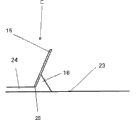
Fig. 4 A illustrates the front view according to enforcement of the present invention of coating unit,
Fig. 4 B illustrates the side view according to enforcement of the present invention of coating unit,
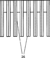
Fig. 5 A illustrates another front view according to enforcement of the present invention of applying device,
Fig. 5 B illustrate applying device this another according to the vertical view of enforcement of the present invention,
Fig. 6 A, Fig. 6 B and Fig. 6 C illustrate device another front view according to enforcement of the present invention, side view and vertical view and
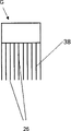
Fig. 7 A, 7B illustrate front view and the side view of another embodiment.
The specific embodiment
Fig. 1 shows the principles of construction according to the device for the manufacture of three dimensional object of the present invention.This member is positioned tectonic province central authorities.Laser beam (2) from laser instrument (1) by means of scanning system (3) pass lens (8) be directed into being conditioned of object to be constituted (5) temperature and deactivation, preferably use on the powder surface (4) of nitrogen deactivation.At this, the task of lens be with remaining optical module for example scanner mirror with the structure space environment separate.These lens usually are implemented as F-Theta(θ) lens combination, in order to guarantee to focus on as far as possible uniformly in whole workspace.Be used for to treat that the coating unit (7) that solidification material is coated on the structure platform (6) is positioned at the structure space, wherein said coating unit constitutes with the slide plate form, and the limit towards powder of described slide plate is implemented as discrete straight line and can be perpendicular to applying direction and being parallel to the tectonic province plane motion.
In addition preferably, this device has for the heating element heater of temperature is regulated in the structure space.Therefore, this structure space for example can be adjusted to for making the desirable temperature of three dimensional object.
Front view according to traditional coating unit of prior art has been shown in Fig. 2 A.This coating unit is implemented as funnel, and it constitutes by two brushes that are fixedly linked (17) and (18).In funnel, carry out the powder metering from last.The part towards the tectonic province plane of coating unit is implemented as the continuous face (12) of no recess, and described (12) limit by two straight flanges (13) and (14).Powder (11) is applied on the previous layer or on tectonic province plane (10).The side view of this enforcement has been shown in Fig. 2 B.
The front view of another traditional coating unit has been shown in Fig. 3 A.This coating unit is implemented as the simple rectangular brush (15) of the no recess that applies powder bed (24).At this, powder to be applied (16) by means of brush (15) formerly the layer or tectonic province plane (23) on smear.Here, also be implemented as continuous face towards the limit (25) on tectonic province plane.In Fig. 3 B, side view has been shown.Not only can be from descending and can carrying from carrying out powder in this enforcement.
The front view according to enforcement of the present invention of coating unit has been shown in Fig. 4 A.Here, this coating unit is implemented as simple brush (19), and it applies powder bed (22).At this, powder to be applied (20) utilize brush (19) formerly the layer or tectonic province plane (21) on smear.As what can find out in the side view shown in Fig. 4 B, unlike the prior art, the limit towards the tectonic province plane of brush (26) is not implemented to continuous straight line.The share in the zone of vacating preferably is 70% at the most and is 30% at least about the length overall towards the limit on tectonic province plane.The share in the zone of vacating is preferably between 40% and 60%.The share in the zone of vacating is particularly preferably between 45% and 55%.This device is positioned to and makes this device can vibrate translational motion, its position change vector and coating direction vertically and with tectonic province plane parallel ground orientation.Not only can be from descending and can carrying from carrying out powder in this enforcement.
Brush for example can be made by metal or plastic material.Preferably use and when applying powder, irreversibly be diverted or deflection and be not flexible material therefore.
Another front view according to enforcement of the present invention of device has been shown in Fig. 5 A.Here, this coating unit is implemented as the brush (27) that simply applies powder bed (30).At this, powder to be applied (28) utilize brush (27) formerly the layer or tectonic province plane (29) on smear.Unlike the prior art, this brush is not implemented to the smooth face of rectangle, that is to say this coating unit at least preferably have have two at least, at least five crimpings (Sicken) (31) especially.Implement by this, the limit towards the tectonic province plane of brush is not implemented to straight line equally.In the vertical view shown in Fig. 5 B, can find out this embodiment.Angle in the tip of crimping (31) should be less than 150 °.This angle is preferably less than 120 °.This angle is especially preferably less than 90 °.The spacing at crimping tip preferably is 3mm and maximum 50mm at least.This device is positioned to and makes this device can vibrate translational motion, its position change vector and coating direction vertically and with tectonic province plane parallel ground orientation.
Another front view according to enforcement of the present invention, side view and the vertical view of device have been shown in Fig. 6 A, Fig. 6 B and Fig. 6 C.Here, coating unit is implemented as the brush (32) that applies powder bed (35).At this, powder to be applied (33) utilize brush (32) formerly the layer or tectonic province plane (34) on smear.In this is implemented, the enforcement shown in Fig. 4 A and Fig. 4 B with make up at the embodiment shown in Fig. 5 A and Fig. 5 B.This device is positioned to and makes this device can vibrate translational motion, its position change vector and coating direction vertically and with tectonic province plane parallel ground orientation.
For the powder that improves applies, with a plurality of combination the in the described embodiment so far.The recess at the brush place of series connection can be designed such that to generate general powder bed.So can abandon the oscillating movement of device in this case.
At Fig. 7 A(front view) and the 7B(side view) in another embodiment has been shown.Carrying out powder by many rows (38) silks (39) applies.
By smoothly smearing tectonic province plane by means of roller or brush by means of carrying out according to device of the present invention after powder applies, the quality of the layer that is applied in can additionally be enhanced.Roller or brush can be selected from metal, pottery and high temperature plastics.The high temperature plastics that is fit to for example is polyimides, PAEK, polyphenol sulfide (Polyphenolensulfide), polyarylsulfone (PAS) or fluoropolymer polymer.
In another embodiment, can additionally contain vibration machine for the device of making three dimensional object layer by layer, it makes structure platform (6) place vibration, in order to so improve the density of powder accumulation.
If make powder to be applied loosening regularly, then the applying property for powder is favourable.This can realize by making suitable device pass powder rotation or translational motion to be applied.This can realize also during powder applies or realize when metering process.By this measure, in powder to be applied, resist piece and form.
Just in time thin and the laxity difference or can not loose powder be easy to be attached to be used to apply powder according to one type of prior art syringe.So these attachments cause groove in tectonic province when powder applies.These attachments can be by means of scratch device, for example remove by means of hairbrush.The known this scratch device of technical staff.Be used for device that powder applies at strigil (Abstreifer) so cross and be removed and fall overfall at this attachment.The material of strigil is chosen to make to guarantee to have enough power to remove at the attachment that is used for the device place that powder applies, yet the damage of the device that applies for powder does not take place simultaneously.Strigil for example can be made up of plastics or metal.
The method that is used for making layer by layer three dimensional object is theme of the present invention equally, wherein by means of working according to coating unit of the present invention (7) another power the power on applying direction on the powder, described another power is perpendicular to the coating direction and be parallel to tectonic province plane earth aligning during powder applies for powder.Especially be preferred for making layer by layer the method for three dimensional object, wherein said method is implemented in device, described device comprises structure space (10), described structure space (10) has Height Adjustable structure platform (6), the layer that is used for the powder that can solidify by electromagnetic radiation is coated to the device (7) on the structure platform (6), be used for radiating layer and the radiation appliance corresponding position of object (5), described radiation appliance comprises the radiation source (1) of launching electromagnetic radiation, control module (3) and be arranged in the lens (8) of electromagnetic radiation light path, and wherein during applying coagulable powder the power on applying direction on the powder perpendicular to the coating direction be parallel to the power that the tectonic province plane earth aims at and work.
Described method especially be suitable for applying the laxity difference or can not be loose and or very thin polymer powder.
Be described in more detail below according to method of the present invention, utilize the described method can be by the powder manufacturing according to profiled member of the present invention, and the present invention should not be limited to this.
All known polymer powders of technical staff are adapted in principle according to device of the present invention or according to using in the method for the present invention.Thermoplastic and thermoelasticity style such as polyethylene (PE, HDPE, LDPE), polypropylene (PP), polyamide, polyester, polyester ester (Polyesterester), polyether ester, polyphenylene oxide, polyacetals, polyalkylene terephthalates, especially PETG (PET) and polybutylene terephthalate (PBT) (PBT), polymethyl methacrylate (PMMA), Pioloform, polyvinyl acetal, polyvinyl chloride (PVC), polyphenylene oxide (PPO), polyoxyethylene methylene (POM), polystyrene (PS), acrylonitrile-butadiene-styrene (ABS) (ABS), Merlon (PC), polyether sulfone, thermoplastic polyurethane (TPU), PAEK, especially polyether-ether-ketone (PEEK), PEKK (PEKK), polyether-ketone (PEK), polyether ether ketone ketone (PEEKK), polyarylether ether ether ketone (PEEEK) or polyetherketoneetherketoneketone (PEKEKK), PEI (PEI), poly arylidene thio-ester, especially polyphenylene sulfide (PPS), TPI (PI), polyamidoimide (PAI), polyvinylidene fluoride, and the copolymer of these thermoplastics PAEK (PAEK)/polyether sulphone (PAES) copolymer for example, mixture and/or polymer blend are especially suitable.Polymer powder preferably includes at least a polyamide or PAEK especially.Quite particularly preferred polymer powder contains polyamide or is made up of described polyamide, especially PA6, PA66, PA610, PA613, PA1010, PA106, PA11, PA12, PA1012, PA1013 or these mixture.
Be fit in addition by for example containing iron, titanium or aluminium or by these metal dusts of forming, or ceramic powders.The preferred polymer powder that uses.
Be in operation usually at first in computer wait based on designing program generate or storage about the data of the shape of object to be manufactured.For manufacturing object, these data are so processed, make this object be broken down into a large amount of levels, than the thin layer of object size, and for example provide shape data with the form of data group, for example cad data in described a large amount of layers each.At this, can be before manufacturing also or with making each layer side by side be each layer generation and deal with data.
Then construct platform (6) and at first drive towards the extreme higher position by means of arrangement for adjusting height, in this position, the surface of structure platform (6) is in the plane with the surface in structure space, and the numerical value of the set thickness of first material layer that then descends, make to constitute the zone that descends in the recess (Ausschnitt) that forms, the zone of described decline is limited by the wall of recess in the side and is limited by the surface of constructing platform (6) below.The ground floor that will have a material to be solidified of set bed thickness by means of coating unit (7) is incorporated in the zone of the cavity that is made of recess and structure platform (6) or decline and is warmed to suitable operating temperature by heater in case of necessity then, for example 100 ℃ to 360 ℃, preferred 120 ℃ to 200 ℃.Then control module (3) is controlled to transfer and makes the light beam (2) that is diverted penetrate in succession on all positions of layer and sintering or melted material there.At first can constitute solid substrate in this way.In second step, structure platform (6) is incorporated into second material layer in the zone of the decline that forms thus in the recess by means of the numerical value of a bed thickness of arrangement for adjusting height decline and by means of coating unit (7), is heated by heater again in case of necessity.
In one embodiment, transfer can be controlled to by control module (3) specifically and make the light beam (2) be diverted only be mapped on the zone of material layer and inner face adjacency recess and there by sintering solidification material layer, form first parietal layer that wall thickness is about 2 to 10mm for example ring-type thus, the remaining powder shape material of its complete embracing layer.Therefore, this part of control device is the chamber wall for generation of encirclement object to be constituted (5), the while constitutes object in every layer equipment.
With as above-mentioned identical mode structure platform (6) has been descended after numerical value, coating material and the heating of bed thickness of time one deck, can begin manufacturing object (5) itself now.For this reason, control module (3) is controlled to transfer and makes the light beam (2) that is diverted penetrate on such position of layer, and described position should correspondingly be solidified with the coordinate that is stored in the control module of object to be manufactured (5).In other layer, carry out similarly.Make on hope ground under the annular wall zone situation of chamber wall form, described chamber wall surrounds object together with remaining, unsintered material and therefore drops to workbench following time and prevent that material from overflowing will constructing platform (6), by means of equipment the ring-type parietal layer is sintered on the ring-type parietal layer below being positioned in each object layer.If use the 1037739 corresponding containers of replacing container or fixedly packing into EP, then can abandon generating wall.
After cooling, the object that constitutes can take out from this device.
Using three dimensional object or member according to the inventive method manufacturing is theme of the present invention equally.
Another theme of the present invention is the application for the polymer powder of making three dimensional object layer by layer, has the particle mean size d50 less than 50 μ m, and it is according to DIN EN ISO 6186(method A, through-flow diameter 15mm) can not flow.Preferably have the polymer powder less than the d50 value of 35 μ m, it can not flow according to DIN EN ISO 6186.At this, particularly preferably be the polymer powder that has less than the d50 value of 20 μ m, it can not flow according to DIN EN ISO 6186.
At this, (the dry measurement adds 20-40 g powder by means of the dry dispersing apparatus of Scirocco to the d50 value by means of Malvern Mastersizer 2000 measurements.The feed rate of vibra shoot is 70%, and disperses air pressure to be in 3 bar.The sample measurement time is 5 seconds (5000 single measurements), and refractive index and blue light value are determined with 1.52.By the Mie theoretical appraisal).
The size accuracy of three dimensional object can be improved by the using polymer powder, and described polymer powder has the 6m that is according to ISO 9277 at least
2The BET surface of/g.Particularly advantageous is to use the 8m that is at least that has according to ISO 9277
2The polymer powder on the BET surface of/g.Quite particularly advantageous is to use the 10m that is at least that has according to ISO 9277
2The polymer powder on the BET surface of/g.
In the scope of the invention, the BET surface is measured according to ISO 9277, using Micromeritics TriStar in discontinuous volumetry, to adsorb by nitrogen gas for 3000 times: 7 measurement points when relative pressure P/P0 is between about 0.05 and about 0.20, by He(helium) (99.996%) carry out dead volume calibration, sample prepares that 1h+at 16 h during at 80 ℃ under the vacuum, special surface relates to degassing sample in the time of 23 ℃.Assessment is determined to carry out by means of multiple spot.
Above-mentioned thermoplastic and thermoelastic gonosome are the polymer powders that is fit to.
The technical staff becomes known for making the process according to polymer powder of the present invention.Here, for example can enumerate jet drying, fusing injection, anionic polymerisation or cold grinding.Be to precipitate (Umf llen) again according to the present invention for the manufacture of the particularly suitable method of powder.At this, polymer in suitable solvent, dissolve and then crystallization separate out.
Even without other enforcement, think that also the technical staff can use foregoing description in the widest scope.Therefore, preferred embodiment and example only should be understood to descriptive and disclosing of limiting in any way anything but.
List of reference signs
A is for the manufacture of the device (Fig. 1) of three dimensional object
1 radiation source, laser instrument
2 laser beams
3 scanning systems
4 powder surfaces
5 objects to be constituted
6 structure platforms
7 be used for to apply the device of the layer of the material that can solidify by electromagnetic radiation
8 lens
9 overflow vessels
40 structure spaces
B coating unit (prior art; Fig. 2 A, 2B)
10 tectonic province planes
11 (to be applied) powder
The continuous face of 12 no recesses
13 first straight flanges
14 second straight flanges
17 brushes
18 brushes
19 limits towards the tectonic province plane
C coating unit (prior art; Fig. 3 A, 3B)
15 brushes
16(is to be applied) powder
23 tectonic province planes
24(is to be applied) powder
25 limits towards the tectonic province plane
D is according to coating unit of the present invention (Fig. 4 A, 4B)
19 brushes
20 (to be applied) powder
21 tectonic province planes
22 powder beds
The limit of 26 brushes
E is according to coating unit of the present invention (Fig. 5 A, 5B)
The limit of 26 brushes
27 brushes
28 (to be applied) powder
29 tectonic province planes
30 powder beds
31 crimpings
F is according to coating unit of the present invention (Fig. 6 A-6C)
The limit of 26 brushes
32 brushes
33 (to be applied) powder
34 tectonic province planes
35 powder beds
36 crimpings
G is according to coating unit of the present invention (Fig. 7 A, 7B)
The limit of 26 brushes
38 rows
39.
Set forth the present invention in more detail according to example below.Alternative embodiments of the present invention can obtain in a similar fashion.
Example:
If explanation is not in addition correspondingly inquired into example with following description.Preheated 180 minutes of chamber of structure is to the temperature that is lower than 20 ℃ of process temperatures.The temperature of constructing afterwards in the chamber is raised to process temperature.The distribution of the temperature in the structure space is not all uniform always, and therefore the temperature of measuring by means of pyrometer is defined as structure space/process temperature.Before first exposure, apply 40 layers of powder that bed thickness respectively is 150 μ m.Laser beam (2) by means of scanning system (3) from laser instrument (1) pass lens (8) be directed into be conditioned temperature and deactivation (N
2) tectonic province plane (4) on.These lens are implemented as the F-Theta lens combination, in order to guarantee to focus on as far as possible uniformly on whole tectonic province plane.
Member to be exposed is positioned tectonic province central authorities.The length of side is that the facing of 50mm carries out fusion by means of laser instrument.Make structure platform (6) decline 0.15mm afterwards and apply new powder bed by means of common coating unit or according to slide plate of the present invention (7) with the speed of 100mm/s.Follow corresponding position and carry out sintering by means of laser instrument.Repeat these steps up to forming the high three-dimensional structure (5) of 50mm.Behind end exposure, before heating element heater shutoff and cooling stage are begun, also apply other 40 layers.During whole construction process, be lower than 40s for the required time of one deck respectively.
After at least 12 hours cool time, member is removed and removes the powder that adheres to.
Example 1(is not according to of the present invention)
This construction process is carried out at the EOSINT P360 of EOS limited company of company.The PA12 powder of powder characteristics value with table 1 is processed.Powder utilizes as shown in Figure 2, and the plater of EOSINT P360 applies.The quality of the powder bed that applies is poor.In tectonic province, can recognize groove.On some position on tectonic province plane, do not apply or apply powder very little.Process temperature is 169 ℃.Exposure parameter is: laser power 19.0W, sweep speed 1100mm/s, exposed lines spacing 0.3mm.The three dimensional object of making has strong blemish.
Example 2(is not according to of the present invention)
This construction process is carried out at the EOSINT P380 of EOS limited company of company.The PA12 powder of powder characteristics value with table 1 is processed.Powder utilizes as shown in Figure 2, and the plater of EOSINT P380 applies.The quality of the powder bed that applies is poor.In tectonic province, can recognize groove.On some position on tectonic province plane, do not apply or apply powder very little.Process temperature is 170 ℃.Exposure parameter is: laser power 36.0W, sweep speed 2000mm/s, exposed lines spacing 0.3mm.The three dimensional object of making has strong blemish.
Example 3(is not according to of the present invention)
This construction process is carried out at the FORMIGA of EOS limited company of company.The PA12 powder of powder characteristics value with table 1 is processed.According to prior art, the conventional coatings device of the FORMIGA shown in powder utilization such as Fig. 3 A/3B applies.The quality of the powder bed that applies is poor.In the big zone on tectonic province plane, do not apply or apply powder very little.It is impossible making three dimensional object.Process temperature is 166 ℃.
Example 4(is not according to of the present invention)
This construction process is carried out at the EOSINT P360 of EOS limited company of company.The PP powder of powder characteristics value with table 3 is processed.Powder utilizes as shown in Figure 2, and the plater of EOSINT P360 applies.The quality of the powder bed that applies is poor.In tectonic province, can recognize dark groove.On many positions on tectonic province plane, do not apply or apply powder very little.Process temperature is 123 ℃.It is impossible making three dimensional object.
Example 5(is not according to of the present invention)
This construction process is carried out at the EOSINT P360 of EOS limited company of company.The PEEK powder of powder characteristics value with table 4 is processed.Powder utilizes as shown in Figure 2, and the plater of EOSINT P360 applies.Process temperature is 199 ℃.The quality of the powder bed that applies be the difference maybe can not apply continuous powder bed.
Example 6(is according to of the present invention)
This test is carried out in the structure space of the EOSINT P360 of EOS limited company of company.The PA12 powder of powder characteristics value with table 1 is processed.Process temperature is 169 ℃.The powder use device applies, and 4 brushes are installed with the spacing of 10mm one by one under described device situation.The geometry of each brush has been shown in Fig. 4 A/4B.Recess is respectively that 10mm is wide.The share in the zone of vacating is 50%.It is that 4mm and frequency are the vibration translational motion of 10Hz that this device carries out amplitude, and it is vertical with the coating direction and directed with tectonic province plane parallel ground that its position changes vector, in order to guarantee the even distribution of powder.Powder can apply no problem.The tectonic province plane is by complete coating.Exposure parameter is: laser power 36.0W, sweep speed 2000mm/s, exposed lines spacing 0.3mm.The three dimensional object of making does not have blemish.
Example 7(is according to of the present invention)
This test is carried out in the structure space of the EOSINT P360 of EOS limited company of company.The PA12 powder of powder characteristics value with table 1 is processed.Process temperature is 169 ℃.Powder utilizes its geometry to apply at the device shown in Fig. 5 A/5B.The angle at the tip of crimping is 90 °.It is that 1mm and frequency are the vibration translational motion of 100Hz that this device carries out amplitude, and it is vertical with the coating direction and directed with tectonic province plane parallel ground that its position changes vector.Powder can apply no problem.The tectonic province plane is by complete coating.Exposure parameter is: laser power 36.0W, sweep speed 2000mm/s, exposed lines spacing 0.3mm.The three dimensional object of making does not have blemish.
Example 8(is according to of the present invention)
This test is carried out in the structure space of the EOSINT P360 of EOS limited company of company.The PA12 powder of powder characteristics value with table 1 is processed.Process temperature is 169 ℃.The powder use device applies, and 2 brushes are installed with the spacing of 25mm one by one under described device situation.Steel rider (diameter 25mm) for level and smooth tectonic province plane is installed in the brush back.The geometry of brush has been shown in Fig. 6 A/6B/6C.Recess is respectively that 12mm is wide.The share in the zone of vacating is 55%.The angle at the tip of crimping is 80 °.It is that 4mm and frequency are the vibration translational motion of 20Hz that this device carries out amplitude, and it is vertical with the coating direction and directed with tectonic province plane parallel ground that its position changes vector.Powder can apply no problem.The tectonic province plane is by complete coating.Exposure parameter is: laser power 36.0W, sweep speed 2000mm/s, exposed lines spacing 0.3mm.The three dimensional object of making does not have blemish.
Example 9(is according to of the present invention)
This test is carried out in the structure space of the EOSINT P360 of EOS limited company of company.The PA12 powder of powder characteristics value with table 1 is processed.Process temperature is 169 ℃.The device of the comb shape shown in powder utilization such as Fig. 7 A/7B applies.This device is made up of the bristle (60 bristles on bristle lengths 20mm, diameter 1mm, the 100mm length) that 10 rows (row's spacing 3mm) are made by brass.It is that 2mm and frequency are the vibration translational motion of 100Hz that this device carries out amplitude, and it is vertical with the coating direction and directed with tectonic province plane parallel ground that its position changes vector.Powder can apply no problem.The tectonic province plane is by complete coating.Exposure parameter is: laser power 36.0W, sweep speed 2000mm/s, exposed lines spacing 0.3mm.The three dimensional object of making does not have blemish.
Example 10(is according to of the present invention)
This test is carried out in the structure space of the EOSINT P360 of EOS limited company of company.The PA6 powder of powder characteristics value with table 2 is processed.The device of the comb shape shown in powder utilization such as Fig. 7 A/7B applies.This device is made up of the bristle (60 bristles on bristle lengths 20mm, diameter 1mm, the 100mm length) that 8 rows (row's spacing 3mm) are made by brass.It is that 1mm and frequency are the vibration translational motion of 200Hz that this device carries out amplitude, and it is vertical with the coating direction and directed with tectonic province plane parallel ground that its position changes vector.Powder can apply no problem.The tectonic province plane is by complete coating.Process temperature is 199 ℃.Exposure parameter is: laser power 36.0W, sweep speed 2000mm/s, exposed lines spacing 0.3mm.The three dimensional object of making does not have blemish.
Example 11(is according to of the present invention)
This test is carried out in the structure space of the EOSINT P360 of EOS limited company of company.The PP powder of powder characteristics value with table 3 is processed.Process temperature is 123 ℃.The powder use device applies, and 3 brushes are installed with the spacing of 20mm one by one under described device situation.The geometry of two brushes has been shown in Fig. 6 A/6B/6C.The 3rd brush is implemented as corresponding with Fig. 5 A/5B.The recess of two brushes is respectively that 12mm is wide.The share in the zone of vacating is 55%.Angle in the tip of crimping is respectively 80 °.It is that 2mm and frequency are the vibration translational motion of 50Hz that this device carries out amplitude, and it is vertical with the coating direction and directed with tectonic province plane parallel ground that its position changes vector.Powder can apply no problem.The tectonic province plane is by complete coating.Exposure parameter is: laser power 36.0W, sweep speed 2000mm/s, exposed lines spacing 0.3mm.The three dimensional object of making does not have blemish.
Example 12(is according to of the present invention)
This test is carried out in the structure space of the EOSINT P360 of EOS limited company of company.The PEEK powder of powder characteristics value with table 4 is processed.Process temperature is 199 ℃.The powder use device applies, and 3 brushes are installed with the spacing of 20mm one by one under described device situation.The geometry of two brushes has been shown in Fig. 6 A/6B/6C.The 3rd brush is implemented as corresponding with Fig. 5 A/5B.The recess of two brushes is respectively that 12mm is wide.The share in the zone of vacating is 55%.Angle in the tip of crimping is respectively 80 °.It is that 5mm and frequency are the vibration translational motion of 40Hz that this device carries out amplitude, and it is vertical with the coating direction and directed with tectonic province plane parallel ground that its position changes vector.Powder can apply no problem.The tectonic province plane is by complete coating.
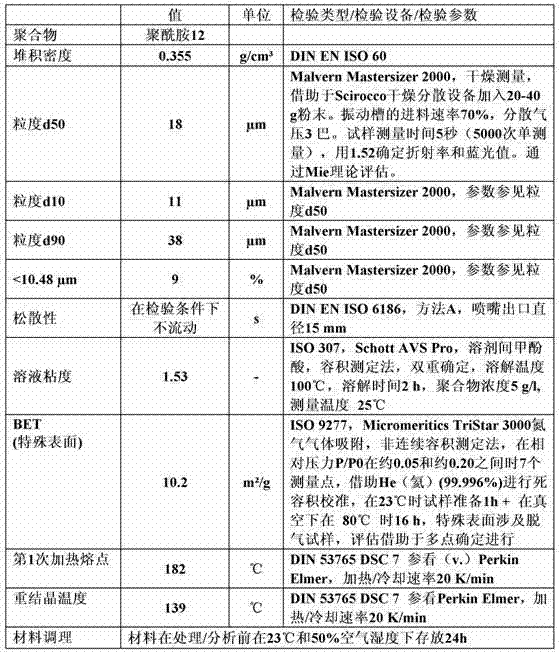
The powder characteristics value of table 1:PA12 powder.

The powder characteristics value of table 2:PA6 powder.

Table 3: the powder characteristics value of polypropylene powder.
The powder characteristics value of table 4:PEEK powder.
Claims (14)
1. be used for making layer by layer the device of three dimensional object, it comprises structure space (40), described structure space (40) has Height Adjustable structure platform (6), the layer that is used for the material that can solidify by electromagnetic radiation is coated to the device (7) on the structure platform (6), be used for radiating layer and the radiation appliance corresponding position of object (5), described radiation appliance comprises the radiation source (1) of launching electromagnetic radiation, control module (3) and be arranged in the lens (8) of electromagnetic radiation light path, the device (7) that wherein is used for coat is embodied as scraper plate, and the limit (26) towards the layer of the material that can solidify by electromagnetic radiation of described scraper plate has recess and can be perpendicular to applying direction and being parallel to the tectonic province plane motion.
2. device according to claim 1 is characterized in that, coating unit (7) has at least two recesses.
3. device according to claim 1 and 2 is characterized in that, coating unit (7) has at least two crimpings.
4. device according to claim 3 is characterized in that, the size of the angle in the tip of described crimping is 150 ° at the most.
5. device according to claim 1 and 2 is characterized in that, about the length overall towards the limit on tectonic province plane, described recess is 30% at least and is 70% at the most in the share on the limit of powder.
6. device according to claim 1 and 2 is characterized in that, described powder applies by means of the coating unit (7) of comb shape.
7. device according to claim 1 and 2 is characterized in that, with a plurality of coating units (7) combination mutually.
8. device according to claim 1 and 2 is characterized in that, makes described coating unit (7) perpendicular to applying direction and being parallel to the tectonic province plane motion.
9. device according to claim 1 and 2 is characterized in that, described coating unit (7) involving vibrations generator.
10. be used for making layer by layer the method for three dimensional object, it is characterized in that, described powder by means of apply according to the described coating unit of one of claim 1 to 9 (7) and during powder applies the power on applying direction on the powder another power work, described another power is perpendicular to the coating direction and be parallel to the tectonic province plane earth and aim at.
11. method according to claim 10 is characterized in that, powder to be applied is become flexible by rotation or the translational motion of coating unit (7).
12., it is characterized in that the described coating unit (7) that applies for powder is removed attachment by means of scratch device according to claim 10 or 11 described methods.
13. have the application less than the polymer powder of the particle mean size d50 of 50 μ m, be used for making layer by layer three dimensional object, described polymer powder according to DIN EN ISO 6186, also be that method A, through-flow diameter 15mm can not flow.
14. three dimensional object or the member made according to the method for claim 10 to 12.
Applications Claiming Priority (2)
| Application Number | Priority Date | Filing Date | Title |
|---|---|---|---|
| DE201210200161 DE102012200161A1 (en) | 2012-01-06 | 2012-01-06 | Device for the layered production of three-dimensional objects |
| DE102012200161.1 | 2012-01-06 |
Publications (2)
| Publication Number | Publication Date |
|---|---|
| CN103192530A true CN103192530A (en) | 2013-07-10 |
| CN103192530B CN103192530B (en) | 2016-10-12 |
Family
ID=47357987
Family Applications (1)
| Application Number | Title | Priority Date | Filing Date |
|---|---|---|---|
| CN201310001373.6A Active CN103192530B (en) | 2012-01-06 | 2013-01-04 | For manufacturing the apparatus and method of three dimensional object layer by layer |
Country Status (6)
| Country | Link |
|---|---|
| US (1) | US20130177767A1 (en) |
| EP (1) | EP2612747B1 (en) |
| JP (1) | JP6057719B2 (en) |
| CN (1) | CN103192530B (en) |
| DE (1) | DE102012200161A1 (en) |
| ES (1) | ES2601478T3 (en) |
Cited By (3)
| Publication number | Priority date | Publication date | Assignee | Title |
|---|---|---|---|---|
| CN105593004A (en) * | 2013-11-22 | 2016-05-18 | 维也纳科技大学 | Device for processing photopolymerizable material for layer-by-layer construction of molding |
| CN107530963A (en) * | 2015-03-13 | 2018-01-02 | 伊科斯湾有限责任公司 | 3D printer with coating unit and coating unit cleaner |
| CN107803502A (en) * | 2017-12-08 | 2018-03-16 | 中国航天科技集团公司长征机械厂 | Selective laser fusing shaping vibration equipment power spreading device |
Families Citing this family (20)
| Publication number | Priority date | Publication date | Assignee | Title |
|---|---|---|---|---|
| DE102012207609A1 (en) * | 2012-05-08 | 2013-11-14 | Evonik Industries Ag | METHOD FOR THE LAYERED MANUFACTURE OF THREE-DIMENSIONAL OBJECTS |
| CH710441A2 (en) * | 2014-12-02 | 2016-06-15 | Rowak Ag | Powdered compositions of thermoplastics and use of the compositions. |
| DE102015201686A1 (en) * | 2015-01-30 | 2016-08-04 | Siemens Aktiengesellschaft | Additive manufacturing process using thicker powder layers and component |
| WO2016147681A1 (en) * | 2015-03-16 | 2016-09-22 | 株式会社リコー | Powder material for three-dimensional modeling, three-dimensional modeling material set, method for producing three-dimensional model, apparatus for producing three-dimensional model, and three-dimensional model |
| EP3117985A1 (en) * | 2015-07-13 | 2017-01-18 | Airbus Operations GmbH | Additive manufacturing system and method for performing additive manufacturing on thermoplastic sheets |
| CN108025490A (en) | 2015-08-28 | 2018-05-11 | 福姆实验室公司 | Increasing material manufacturing process optimization technology and related system and method |
| RU2647976C1 (en) * | 2016-09-05 | 2018-03-21 | Федеральное государственное автономное образовательное учреждение высшего образования Санкт-Петербургский политехнический университет Петра Великого | Device for production of 3d articles with the gradient of properties of powders |
| DE102016219080A1 (en) | 2016-09-30 | 2018-04-05 | Evonik Degussa Gmbh | Polyamide powder for selective sintering |
| CN115260749A (en) * | 2016-10-17 | 2022-11-01 | 捷普有限公司 | Precipitation of polyether block amides and thermoplastic polyethylene to enhance operating window for three-dimensional printing |
| US10569364B2 (en) * | 2017-01-06 | 2020-02-25 | General Electric Company | Systems and methods for additive manufacturing recoating |
| US11167454B2 (en) | 2017-01-13 | 2021-11-09 | General Electric Company | Method and apparatus for continuously refreshing a recoater blade for additive manufacturing |
| EP3523111A4 (en) * | 2017-01-27 | 2020-08-05 | Hewlett-Packard Development Company, L.P. | Automatic spreader bar blade material positioning for additive manufacturing |
| US10682725B2 (en) * | 2017-11-30 | 2020-06-16 | The Boeing Company | Microstructure refinement methods by mechanical work for additive manufactured materials |
| EP3501695A1 (en) | 2017-12-22 | 2019-06-26 | Evonik Degussa GmbH | Device for the layered production of three-dimensional objects and process |
| JP7099213B2 (en) * | 2018-09-14 | 2022-07-12 | 株式会社Ihi | Laminated modeling equipment and laminated model manufacturing method |
| EP3628422A1 (en) | 2018-09-28 | 2020-04-01 | The Boeing Company | Powder dispensing unit, powder spreading unit, and a vibratory compaction system of an additive manufacturing system and methods therefor |
| DE102018128242A1 (en) * | 2018-11-12 | 2020-05-14 | SLM Solutions Group AG | Powder application device, method for operating a powder application device and system for producing a three-dimensional workpiece |
| CN115943040A (en) * | 2018-12-26 | 2023-04-07 | 三菱化学株式会社 | Powder for powder lamination molding method and method for producing same |
| CN109909501A (en) * | 2019-03-15 | 2019-06-21 | 沈阳工业大学 | A kind of powder feeder and powder delivery method that simultaneously pre-heating powder can be dried based on laser gain material manufacture |
| EP3943220A1 (en) * | 2020-07-24 | 2022-01-26 | Aixway3D GmbH | Device and method for a powder system for improved powder application efficiency in an additive manufacturing method |
Citations (4)
| Publication number | Priority date | Publication date | Assignee | Title |
|---|---|---|---|---|
| US5252264A (en) * | 1991-11-08 | 1993-10-12 | Dtm Corporation | Apparatus and method for producing parts with multi-directional powder delivery |
| US20020152002A1 (en) * | 2001-02-21 | 2002-10-17 | Markus Lindemann | Process and device for producing a shaped body by selective laser melting |
| CN1911635A (en) * | 2005-08-08 | 2007-02-14 | 赖维祥 | Fast shaping device for making body from image of computer and with printing machine |
| CN1942505A (en) * | 2004-02-27 | 2007-04-04 | 德古萨公司 | Polymer powder comprising a copolymer, use in a shaping method which uses a non-focussed application of energy and moulded body that is produced from said polymer powder |
Family Cites Families (16)
| Publication number | Priority date | Publication date | Assignee | Title |
|---|---|---|---|---|
| US4863538A (en) * | 1986-10-17 | 1989-09-05 | Board Of Regents, The University Of Texas System | Method and apparatus for producing parts by selective sintering |
| US5204055A (en) * | 1989-12-08 | 1993-04-20 | Massachusetts Institute Of Technology | Three-dimensional printing techniques |
| DE4134265C2 (en) * | 1991-10-16 | 1993-11-25 | Eos Electro Optical Syst | Device and method for producing a three-dimensional object by means of stereography |
| US5527877A (en) | 1992-11-23 | 1996-06-18 | Dtm Corporation | Sinterable semi-crystalline powder and near-fully dense article formed therewith |
| US5648450A (en) | 1992-11-23 | 1997-07-15 | Dtm Corporation | Sinterable semi-crystalline powder and near-fully dense article formed therein |
| DE19514740C1 (en) * | 1995-04-21 | 1996-04-11 | Eos Electro Optical Syst | Appts. for producing three-dimensional objects by laser sintering |
| SE509088C2 (en) | 1997-04-30 | 1998-12-07 | Ralf Larsson | Methods and apparatus for the production of volume bodies |
| DE19747309B4 (en) * | 1997-10-27 | 2007-11-15 | Degussa Gmbh | Use of a polyamide 12 for selective laser sintering |
| DE19846478C5 (en) | 1998-10-09 | 2004-10-14 | Eos Gmbh Electro Optical Systems | Laser-sintering machine |
| WO2001038061A1 (en) | 1999-10-26 | 2001-05-31 | University Of Southern California | Process of making a three-dimensional object |
| FR2802128B1 (en) * | 1999-12-10 | 2002-02-08 | Ecole Nale Sup Artes Metiers | DEVICE FOR DEPOSITING THIN LAYERS OF POWDER OR POWDER MATERIAL AND METHOD THEREOF |
| DE10251790A1 (en) | 2002-11-07 | 2004-05-19 | Degussa Ag | Composition for fluidized bed-, rotational-, electrostatic-, tribo-, or minicoating in the preparation of cosmetics and paint, comprises polyamide, polyamide derivatives, and flow aid |
| DE10300959C5 (en) * | 2003-01-14 | 2013-10-02 | Cl Schutzrechtsverwaltungs Gmbh | Coater device for a building device for producing molded parts from building material |
| DE10356193A1 (en) | 2003-03-15 | 2004-09-23 | Degussa Ag | Process for the production of three-dimensional objects by means of microwave radiation |
| DE102004020452A1 (en) | 2004-04-27 | 2005-12-01 | Degussa Ag | Method for producing three-dimensional objects by means of electromagnetic radiation and applying an absorber by inkjet method |
| DE102010004036A1 (en) * | 2010-01-05 | 2011-07-07 | EOS GmbH Electro Optical Systems, 82152 | Apparatus for generatively producing a three-dimensional object with continuous heat input |
-
2012
- 2012-01-06 DE DE201210200161 patent/DE102012200161A1/en not_active Ceased
- 2012-12-12 ES ES12196612.1T patent/ES2601478T3/en active Active
- 2012-12-12 EP EP12196612.1A patent/EP2612747B1/en active Active
-
2013
- 2013-01-03 US US13/733,465 patent/US20130177767A1/en not_active Abandoned
- 2013-01-04 CN CN201310001373.6A patent/CN103192530B/en active Active
- 2013-01-07 JP JP2013000609A patent/JP6057719B2/en active Active
Patent Citations (4)
| Publication number | Priority date | Publication date | Assignee | Title |
|---|---|---|---|---|
| US5252264A (en) * | 1991-11-08 | 1993-10-12 | Dtm Corporation | Apparatus and method for producing parts with multi-directional powder delivery |
| US20020152002A1 (en) * | 2001-02-21 | 2002-10-17 | Markus Lindemann | Process and device for producing a shaped body by selective laser melting |
| CN1942505A (en) * | 2004-02-27 | 2007-04-04 | 德古萨公司 | Polymer powder comprising a copolymer, use in a shaping method which uses a non-focussed application of energy and moulded body that is produced from said polymer powder |
| CN1911635A (en) * | 2005-08-08 | 2007-02-14 | 赖维祥 | Fast shaping device for making body from image of computer and with printing machine |
Cited By (5)
| Publication number | Priority date | Publication date | Assignee | Title |
|---|---|---|---|---|
| CN105593004A (en) * | 2013-11-22 | 2016-05-18 | 维也纳科技大学 | Device for processing photopolymerizable material for layer-by-layer construction of molding |
| CN105593004B (en) * | 2013-11-22 | 2017-09-12 | 维也纳科技大学 | For processing photopolymerizable material successively to form the device of formed body |
| CN107530963A (en) * | 2015-03-13 | 2018-01-02 | 伊科斯湾有限责任公司 | 3D printer with coating unit and coating unit cleaner |
| CN107530963B (en) * | 2015-03-13 | 2019-08-23 | 伊科斯湾有限责任公司 | 3D printer with coating unit and coating unit cleaner |
| CN107803502A (en) * | 2017-12-08 | 2018-03-16 | 中国航天科技集团公司长征机械厂 | Selective laser fusing shaping vibration equipment power spreading device |
Also Published As
| Publication number | Publication date |
|---|---|
| ES2601478T3 (en) | 2017-02-15 |
| EP2612747A3 (en) | 2013-09-25 |
| JP6057719B2 (en) | 2017-01-11 |
| EP2612747A2 (en) | 2013-07-10 |
| JP2013141830A (en) | 2013-07-22 |
| US20130177767A1 (en) | 2013-07-11 |
| CN103192530B (en) | 2016-10-12 |
| EP2612747B1 (en) | 2016-08-17 |
| DE102012200161A1 (en) | 2013-07-11 |
Similar Documents
| Publication | Publication Date | Title |
|---|---|---|
| CN103192530B (en) | For manufacturing the apparatus and method of three dimensional object layer by layer | |
| CN103192531B (en) | For manufacturing the apparatus and method of three dimensional object layer by layer | |
| CN103252894B (en) | Method and apparatus for manufacturing three dimensional object layer by layer | |
| US9162392B2 (en) | Apparatus for avoiding deposits on optical components in the laser sintering process | |
| US11801633B2 (en) | Apparatuses for continuously refreshing a recoater blade for additive manufacturing including a blade feed unit and arm portion | |
| US7847057B2 (en) | PAEK powder, in particular for the use in a method for a layer-wise manufacturing of a three-dimensional object, as well as method for producing it | |
| US9238310B2 (en) | Component properties through beam shaping in the laser sintering process | |
| JP2018086757A (en) | Production method of three-dimensional molded article and production device of three-dimensional molded article | |
| US20140079916A1 (en) | Process for the layer-by-layer production of low-warpage three-dimensional objects by means of cooling elements | |
| KR20160091329A (en) | 3d printing method using slip | |
| JP2013022964A (en) | Apparatus and method for manufacturing three-dimensional object in layers, polymer powder and mold | |
| Pignatelli et al. | An application-and market-oriented review on large format additive manufacturing, focusing on polymer pellet-based 3D printing | |
| JP2018015972A (en) | Three-dimensional molding method, molded article and three-dimensional molding apparatus | |
| Dudek et al. | Rapid prototyping: Technologies, materials and advances | |
| Godec et al. | Introduction to additive manufacturing | |
| US20130316145A1 (en) | Process for layer-by-layer production of three-dimentional objects | |
| Whenish et al. | Powder-Bed Fusion of Polymers |
Legal Events
| Date | Code | Title | Description |
|---|---|---|---|
| C06 | Publication | ||
| PB01 | Publication | ||
| C10 | Entry into substantive examination | ||
| SE01 | Entry into force of request for substantive examination | ||
| C41 | Transfer of patent application or patent right or utility model | ||
| TA01 | Transfer of patent application right |
Effective date of registration: 20160114 Address after: essen Applicant after: Evonik Degussa GmbH Address before: essen Applicant before: Evonik Industries AG |
|
| C14 | Grant of patent or utility model | ||
| GR01 | Patent grant | ||
| CP01 | Change in the name or title of a patent holder | ||
| CP01 | Change in the name or title of a patent holder |
Address after: Essen, Germany Patentee after: Evonik Operations Limited Address before: Essen, Germany Patentee before: EVONIK DEGUSSA GmbH |