CN102770080A - Systems, implants, tools, and methods for treatments of pelvic conditions - Google Patents
Systems, implants, tools, and methods for treatments of pelvic conditions Download PDFInfo
- Publication number
- CN102770080A CN102770080A CN2010800648584A CN201080064858A CN102770080A CN 102770080 A CN102770080 A CN 102770080A CN 2010800648584 A CN2010800648584 A CN 2010800648584A CN 201080064858 A CN201080064858 A CN 201080064858A CN 102770080 A CN102770080 A CN 102770080A
- Authority
- CN
- China
- Prior art keywords
- anchor
- tissue
- implant
- expansion
- transvaginal
- Prior art date
- Legal status (The legal status is an assumption and is not a legal conclusion. Google has not performed a legal analysis and makes no representation as to the accuracy of the status listed.)
- Granted
Links
- 239000007943 implant Substances 0.000 title claims abstract description 239
- 238000000034 method Methods 0.000 title claims abstract description 134
- 238000011282 treatment Methods 0.000 title description 18
- 210000001215 vagina Anatomy 0.000 claims description 116
- 210000004446 longitudinal ligament Anatomy 0.000 claims description 47
- 230000033001 locomotion Effects 0.000 claims description 32
- 230000008093 supporting effect Effects 0.000 claims description 32
- 230000007246 mechanism Effects 0.000 claims description 24
- 239000012530 fluid Substances 0.000 claims description 23
- 238000002224 dissection Methods 0.000 claims description 17
- 238000013459 approach Methods 0.000 claims description 16
- 210000004197 pelvis Anatomy 0.000 claims description 16
- 230000008602 contraction Effects 0.000 claims description 15
- 230000007062 hydrolysis Effects 0.000 claims description 12
- 238000006460 hydrolysis reaction Methods 0.000 claims description 12
- 210000001519 tissue Anatomy 0.000 abstract description 194
- 210000003041 ligament Anatomy 0.000 abstract description 90
- 210000003484 anatomy Anatomy 0.000 abstract description 41
- 201000004989 Enterocele Diseases 0.000 abstract description 15
- 206010021639 Incontinence Diseases 0.000 abstract description 14
- 238000004873 anchoring Methods 0.000 abstract description 14
- 206010019909 Hernia Diseases 0.000 abstract description 13
- 206010066218 Stress Urinary Incontinence Diseases 0.000 abstract description 7
- 238000001356 surgical procedure Methods 0.000 abstract description 7
- 210000003205 muscle Anatomy 0.000 abstract description 6
- 208000000921 Urge Urinary Incontinence Diseases 0.000 abstract description 4
- 206010046814 Uterine prolapse Diseases 0.000 abstract description 4
- 206010046494 urge incontinence Diseases 0.000 abstract description 4
- 208000034347 Faecal incontinence Diseases 0.000 abstract description 3
- 208000012287 Prolapse Diseases 0.000 abstract description 3
- 206010038084 Rectocele Diseases 0.000 abstract description 2
- 206010011803 Cystocele Diseases 0.000 abstract 1
- 206010053236 Mixed incontinence Diseases 0.000 abstract 1
- 206010046940 Vaginal prolapse Diseases 0.000 abstract 1
- 239000000463 material Substances 0.000 description 70
- 238000005516 engineering process Methods 0.000 description 49
- 239000013307 optical fiber Substances 0.000 description 36
- 230000006870 function Effects 0.000 description 30
- 238000003384 imaging method Methods 0.000 description 30
- 208000037265 diseases, disorders, signs and symptoms Diseases 0.000 description 28
- -1 polyethylene Polymers 0.000 description 27
- 201000010099 disease Diseases 0.000 description 25
- 239000000835 fiber Substances 0.000 description 23
- 238000005286 illumination Methods 0.000 description 23
- 230000000007 visual effect Effects 0.000 description 22
- 229920000642 polymer Polymers 0.000 description 21
- 229910000831 Steel Inorganic materials 0.000 description 19
- 238000005520 cutting process Methods 0.000 description 19
- 239000010959 steel Substances 0.000 description 19
- 230000003287 optical effect Effects 0.000 description 18
- 229910052751 metal Inorganic materials 0.000 description 16
- 239000002184 metal Substances 0.000 description 16
- 239000004743 Polypropylene Substances 0.000 description 15
- 241000605008 Spirillum Species 0.000 description 15
- 229920001155 polypropylene Polymers 0.000 description 15
- 238000010586 diagram Methods 0.000 description 14
- 210000000988 bone and bone Anatomy 0.000 description 13
- 238000003780 insertion Methods 0.000 description 13
- 230000037431 insertion Effects 0.000 description 13
- 230000008569 process Effects 0.000 description 13
- 230000003187 abdominal effect Effects 0.000 description 12
- 208000013823 pelvic organ prolapse Diseases 0.000 description 12
- 229920003023 plastic Polymers 0.000 description 12
- 239000004033 plastic Substances 0.000 description 12
- 210000004872 soft tissue Anatomy 0.000 description 12
- 230000002829 reductive effect Effects 0.000 description 11
- 230000004048 modification Effects 0.000 description 10
- 238000012986 modification Methods 0.000 description 10
- 210000000664 rectum Anatomy 0.000 description 10
- 230000001105 regulatory effect Effects 0.000 description 9
- 230000002411 adverse Effects 0.000 description 8
- 230000006378 damage Effects 0.000 description 8
- 208000027418 Wounds and injury Diseases 0.000 description 7
- 238000011010 flushing procedure Methods 0.000 description 7
- 229920002635 polyurethane Polymers 0.000 description 7
- 239000004814 polyurethane Substances 0.000 description 7
- 230000008439 repair process Effects 0.000 description 7
- 230000002441 reversible effect Effects 0.000 description 7
- XLYOFNOQVPJJNP-UHFFFAOYSA-N water Substances O XLYOFNOQVPJJNP-UHFFFAOYSA-N 0.000 description 7
- 206010046543 Urinary incontinence Diseases 0.000 description 6
- 230000008901 benefit Effects 0.000 description 6
- 238000013461 design Methods 0.000 description 6
- 239000013536 elastomeric material Substances 0.000 description 6
- 210000003195 fascia Anatomy 0.000 description 6
- 239000007788 liquid Substances 0.000 description 6
- 239000011148 porous material Substances 0.000 description 6
- 208000022170 stress incontinence Diseases 0.000 description 6
- 239000011230 binding agent Substances 0.000 description 5
- 230000005540 biological transmission Effects 0.000 description 5
- 238000010276 construction Methods 0.000 description 5
- 210000003903 pelvic floor Anatomy 0.000 description 5
- 239000007787 solid Substances 0.000 description 5
- 239000000725 suspension Substances 0.000 description 5
- 206010059450 Colpocele Diseases 0.000 description 4
- 238000005452 bending Methods 0.000 description 4
- 239000008280 blood Substances 0.000 description 4
- 210000004369 blood Anatomy 0.000 description 4
- 230000008859 change Effects 0.000 description 4
- 230000006835 compression Effects 0.000 description 4
- 238000007906 compression Methods 0.000 description 4
- 230000036541 health Effects 0.000 description 4
- 230000001976 improved effect Effects 0.000 description 4
- 230000001965 increasing effect Effects 0.000 description 4
- 238000003973 irrigation Methods 0.000 description 4
- 230000002262 irrigation Effects 0.000 description 4
- HLXZNVUGXRDIFK-UHFFFAOYSA-N nickel titanium Chemical compound [Ti].[Ti].[Ti].[Ti].[Ti].[Ti].[Ti].[Ti].[Ti].[Ti].[Ti].[Ni].[Ni].[Ni].[Ni].[Ni].[Ni].[Ni].[Ni].[Ni].[Ni].[Ni].[Ni].[Ni].[Ni] HLXZNVUGXRDIFK-UHFFFAOYSA-N 0.000 description 4
- 229910001000 nickel titanium Inorganic materials 0.000 description 4
- 210000000056 organ Anatomy 0.000 description 4
- 229920002492 poly(sulfone) Polymers 0.000 description 4
- 229920000139 polyethylene terephthalate Polymers 0.000 description 4
- 239000005020 polyethylene terephthalate Substances 0.000 description 4
- 210000002700 urine Anatomy 0.000 description 4
- 239000004698 Polyethylene Substances 0.000 description 3
- FAPWRFPIFSIZLT-UHFFFAOYSA-M Sodium chloride Chemical compound [Na+].[Cl-] FAPWRFPIFSIZLT-UHFFFAOYSA-M 0.000 description 3
- 230000015572 biosynthetic process Effects 0.000 description 3
- 210000004204 blood vessel Anatomy 0.000 description 3
- 239000002775 capsule Substances 0.000 description 3
- 230000001149 cognitive effect Effects 0.000 description 3
- 230000001143 conditioned effect Effects 0.000 description 3
- 208000035475 disorder Diseases 0.000 description 3
- 230000000694 effects Effects 0.000 description 3
- 238000005538 encapsulation Methods 0.000 description 3
- 239000004744 fabric Substances 0.000 description 3
- 230000012010 growth Effects 0.000 description 3
- 210000004247 hand Anatomy 0.000 description 3
- 208000014674 injury Diseases 0.000 description 3
- 238000012423 maintenance Methods 0.000 description 3
- 230000008520 organization Effects 0.000 description 3
- 229920000573 polyethylene Polymers 0.000 description 3
- 239000011780 sodium chloride Substances 0.000 description 3
- 210000005070 sphincter Anatomy 0.000 description 3
- 239000003356 suture material Substances 0.000 description 3
- 239000010409 thin film Substances 0.000 description 3
- 210000003708 urethra Anatomy 0.000 description 3
- RZVAJINKPMORJF-UHFFFAOYSA-N Acetaminophen Chemical compound CC(=O)NC1=CC=C(O)C=C1 RZVAJINKPMORJF-UHFFFAOYSA-N 0.000 description 2
- 240000000233 Melia azedarach Species 0.000 description 2
- 230000009471 action Effects 0.000 description 2
- 230000004913 activation Effects 0.000 description 2
- 239000000654 additive Substances 0.000 description 2
- 230000000996 additive effect Effects 0.000 description 2
- 230000003190 augmentative effect Effects 0.000 description 2
- 239000000560 biocompatible material Substances 0.000 description 2
- 239000003364 biologic glue Substances 0.000 description 2
- 239000012620 biological material Substances 0.000 description 2
- 210000001124 body fluid Anatomy 0.000 description 2
- 239000010839 body fluid Substances 0.000 description 2
- VHRGRCVQAFMJIZ-UHFFFAOYSA-N cadaverine Chemical compound NCCCCCN VHRGRCVQAFMJIZ-UHFFFAOYSA-N 0.000 description 2
- 238000007599 discharging Methods 0.000 description 2
- 230000002708 enhancing effect Effects 0.000 description 2
- 239000003822 epoxy resin Substances 0.000 description 2
- 230000003628 erosive effect Effects 0.000 description 2
- 230000002349 favourable effect Effects 0.000 description 2
- 239000007789 gas Substances 0.000 description 2
- 238000002513 implantation Methods 0.000 description 2
- 238000001727 in vivo Methods 0.000 description 2
- 230000000968 intestinal effect Effects 0.000 description 2
- 208000003243 intestinal obstruction Diseases 0.000 description 2
- 238000002357 laparoscopic surgery Methods 0.000 description 2
- 230000000670 limiting effect Effects 0.000 description 2
- 230000007774 longterm Effects 0.000 description 2
- 238000007726 management method Methods 0.000 description 2
- 238000004519 manufacturing process Methods 0.000 description 2
- 238000002324 minimally invasive surgery Methods 0.000 description 2
- 238000003032 molecular docking Methods 0.000 description 2
- 238000000465 moulding Methods 0.000 description 2
- 210000005036 nerve Anatomy 0.000 description 2
- 210000004303 peritoneum Anatomy 0.000 description 2
- 229920000647 polyepoxide Polymers 0.000 description 2
- 229920000098 polyolefin Polymers 0.000 description 2
- 229920001296 polysiloxane Polymers 0.000 description 2
- 230000001737 promoting effect Effects 0.000 description 2
- 238000012797 qualification Methods 0.000 description 2
- 230000009467 reduction Effects 0.000 description 2
- 238000000926 separation method Methods 0.000 description 2
- 230000000638 stimulation Effects 0.000 description 2
- 238000002560 therapeutic procedure Methods 0.000 description 2
- 238000002604 ultrasonography Methods 0.000 description 2
- 210000004291 uterus Anatomy 0.000 description 2
- 238000004804 winding Methods 0.000 description 2
- SHXWCVYOXRDMCX-UHFFFAOYSA-N 3,4-methylenedioxymethamphetamine Chemical compound CNC(C)CC1=CC=C2OCOC2=C1 SHXWCVYOXRDMCX-UHFFFAOYSA-N 0.000 description 1
- 206010049244 Ankyloglossia congenital Diseases 0.000 description 1
- 206010003694 Atrophy Diseases 0.000 description 1
- 240000004244 Cucurbita moschata Species 0.000 description 1
- 235000009854 Cucurbita moschata Nutrition 0.000 description 1
- 235000009852 Cucurbita pepo Nutrition 0.000 description 1
- 241000255925 Diptera Species 0.000 description 1
- 244000061408 Eugenia caryophyllata Species 0.000 description 1
- PEDCQBHIVMGVHV-UHFFFAOYSA-N Glycerine Chemical class OCC(O)CO PEDCQBHIVMGVHV-UHFFFAOYSA-N 0.000 description 1
- 206010018852 Haematoma Diseases 0.000 description 1
- 241000110847 Kochia Species 0.000 description 1
- 240000000249 Morus alba Species 0.000 description 1
- 235000008708 Morus alba Nutrition 0.000 description 1
- 208000005646 Pneumoperitoneum Diseases 0.000 description 1
- 239000004696 Poly ether ether ketone Substances 0.000 description 1
- 235000016639 Syzygium aromaticum Nutrition 0.000 description 1
- 206010046830 Uterovaginal prolapse Diseases 0.000 description 1
- 206010065441 Venous haemorrhage Diseases 0.000 description 1
- HZEWFHLRYVTOIW-UHFFFAOYSA-N [Ti].[Ni] Chemical compound [Ti].[Ni] HZEWFHLRYVTOIW-UHFFFAOYSA-N 0.000 description 1
- 210000000683 abdominal cavity Anatomy 0.000 description 1
- 230000003213 activating effect Effects 0.000 description 1
- 230000001154 acute effect Effects 0.000 description 1
- 230000003044 adaptive effect Effects 0.000 description 1
- 230000002776 aggregation Effects 0.000 description 1
- 238000004220 aggregation Methods 0.000 description 1
- 239000003570 air Substances 0.000 description 1
- 210000000436 anus Anatomy 0.000 description 1
- 238000003491 array Methods 0.000 description 1
- 230000037444 atrophy Effects 0.000 description 1
- JUPQTSLXMOCDHR-UHFFFAOYSA-N benzene-1,4-diol;bis(4-fluorophenyl)methanone Chemical compound OC1=CC=C(O)C=C1.C1=CC(F)=CC=C1C(=O)C1=CC=C(F)C=C1 JUPQTSLXMOCDHR-UHFFFAOYSA-N 0.000 description 1
- 210000003679 cervix uteri Anatomy 0.000 description 1
- 230000005465 channeling Effects 0.000 description 1
- 238000006243 chemical reaction Methods 0.000 description 1
- 230000035606 childbirth Effects 0.000 description 1
- 238000005345 coagulation Methods 0.000 description 1
- 230000015271 coagulation Effects 0.000 description 1
- 238000004891 communication Methods 0.000 description 1
- 239000002131 composite material Substances 0.000 description 1
- 150000001875 compounds Chemical class 0.000 description 1
- 230000003750 conditioning effect Effects 0.000 description 1
- 210000002808 connective tissue Anatomy 0.000 description 1
- 230000008878 coupling Effects 0.000 description 1
- 238000010168 coupling process Methods 0.000 description 1
- 238000005859 coupling reaction Methods 0.000 description 1
- 230000007423 decrease Effects 0.000 description 1
- 230000002950 deficient Effects 0.000 description 1
- 208000002925 dental caries Diseases 0.000 description 1
- 238000011161 development Methods 0.000 description 1
- 230000000916 dilatatory effect Effects 0.000 description 1
- 238000006073 displacement reaction Methods 0.000 description 1
- 238000009826 distribution Methods 0.000 description 1
- 210000003717 douglas' pouch Anatomy 0.000 description 1
- 239000003814 drug Substances 0.000 description 1
- 229940079593 drug Drugs 0.000 description 1
- 239000013013 elastic material Substances 0.000 description 1
- 230000007613 environmental effect Effects 0.000 description 1
- 229920005570 flexible polymer Polymers 0.000 description 1
- 229920002313 fluoropolymer Polymers 0.000 description 1
- 239000004811 fluoropolymer Substances 0.000 description 1
- 210000000245 forearm Anatomy 0.000 description 1
- 238000010438 heat treatment Methods 0.000 description 1
- 238000009802 hysterectomy Methods 0.000 description 1
- 230000006872 improvement Effects 0.000 description 1
- 238000007373 indentation Methods 0.000 description 1
- 230000005764 inhibitory process Effects 0.000 description 1
- 238000007689 inspection Methods 0.000 description 1
- 238000009434 installation Methods 0.000 description 1
- 238000009413 insulation Methods 0.000 description 1
- 230000002045 lasting effect Effects 0.000 description 1
- 230000004807 localization Effects 0.000 description 1
- 239000000696 magnetic material Substances 0.000 description 1
- 230000013011 mating Effects 0.000 description 1
- 238000004137 mechanical activation Methods 0.000 description 1
- 230000005012 migration Effects 0.000 description 1
- 238000013508 migration Methods 0.000 description 1
- 229920003052 natural elastomer Polymers 0.000 description 1
- 229920001194 natural rubber Polymers 0.000 description 1
- 150000003961 organosilicon compounds Chemical class 0.000 description 1
- 238000012856 packing Methods 0.000 description 1
- 239000003973 paint Substances 0.000 description 1
- 230000000737 periodic effect Effects 0.000 description 1
- 239000011295 pitch Substances 0.000 description 1
- 229920002530 polyetherether ketone Polymers 0.000 description 1
- 238000003825 pressing Methods 0.000 description 1
- 238000007639 printing Methods 0.000 description 1
- 238000012545 processing Methods 0.000 description 1
- 230000000750 progressive effect Effects 0.000 description 1
- 230000001681 protective effect Effects 0.000 description 1
- 210000003689 pubic bone Anatomy 0.000 description 1
- 238000005086 pumping Methods 0.000 description 1
- 238000004080 punching Methods 0.000 description 1
- 238000011084 recovery Methods 0.000 description 1
- 230000000717 retained effect Effects 0.000 description 1
- 238000005096 rolling process Methods 0.000 description 1
- 238000007789 sealing Methods 0.000 description 1
- 230000035807 sensation Effects 0.000 description 1
- 238000009958 sewing Methods 0.000 description 1
- 230000036299 sexual function Effects 0.000 description 1
- 229920002379 silicone rubber Polymers 0.000 description 1
- 239000004945 silicone rubber Substances 0.000 description 1
- 235000020354 squash Nutrition 0.000 description 1
- 150000003431 steroids Chemical class 0.000 description 1
- 238000003860 storage Methods 0.000 description 1
- 229920003051 synthetic elastomer Polymers 0.000 description 1
- 239000005061 synthetic rubber Substances 0.000 description 1
- 210000002435 tendon Anatomy 0.000 description 1
- 238000012360 testing method Methods 0.000 description 1
- 210000003813 thumb Anatomy 0.000 description 1
- 230000008467 tissue growth Effects 0.000 description 1
- 208000037816 tissue injury Diseases 0.000 description 1
- 210000005239 tubule Anatomy 0.000 description 1
- 230000007306 turnover Effects 0.000 description 1
- 230000002485 urinary effect Effects 0.000 description 1
Images


Classifications
-
- A—HUMAN NECESSITIES
- A61—MEDICAL OR VETERINARY SCIENCE; HYGIENE
- A61B—DIAGNOSIS; SURGERY; IDENTIFICATION
- A61B1/00—Instruments for performing medical examinations of the interior of cavities or tubes of the body by visual or photographical inspection, e.g. endoscopes; Illuminating arrangements therefor
- A61B1/06—Instruments for performing medical examinations of the interior of cavities or tubes of the body by visual or photographical inspection, e.g. endoscopes; Illuminating arrangements therefor with illuminating arrangements
-
- A—HUMAN NECESSITIES
- A61—MEDICAL OR VETERINARY SCIENCE; HYGIENE
- A61B—DIAGNOSIS; SURGERY; IDENTIFICATION
- A61B90/00—Instruments, implements or accessories specially adapted for surgery or diagnosis and not covered by any of the groups A61B1/00 - A61B50/00, e.g. for luxation treatment or for protecting wound edges
- A61B90/30—Devices for illuminating a surgical field, the devices having an interrelation with other surgical devices or with a surgical procedure
-
- A—HUMAN NECESSITIES
- A61—MEDICAL OR VETERINARY SCIENCE; HYGIENE
- A61B—DIAGNOSIS; SURGERY; IDENTIFICATION
- A61B1/00—Instruments for performing medical examinations of the interior of cavities or tubes of the body by visual or photographical inspection, e.g. endoscopes; Illuminating arrangements therefor
- A61B1/00064—Constructional details of the endoscope body
- A61B1/00071—Insertion part of the endoscope body
- A61B1/0008—Insertion part of the endoscope body characterised by distal tip features
- A61B1/00082—Balloons
-
- A—HUMAN NECESSITIES
- A61—MEDICAL OR VETERINARY SCIENCE; HYGIENE
- A61B—DIAGNOSIS; SURGERY; IDENTIFICATION
- A61B1/00—Instruments for performing medical examinations of the interior of cavities or tubes of the body by visual or photographical inspection, e.g. endoscopes; Illuminating arrangements therefor
- A61B1/00064—Constructional details of the endoscope body
- A61B1/00071—Insertion part of the endoscope body
- A61B1/0008—Insertion part of the endoscope body characterised by distal tip features
- A61B1/00087—Tools
-
- A—HUMAN NECESSITIES
- A61—MEDICAL OR VETERINARY SCIENCE; HYGIENE
- A61B—DIAGNOSIS; SURGERY; IDENTIFICATION
- A61B1/00—Instruments for performing medical examinations of the interior of cavities or tubes of the body by visual or photographical inspection, e.g. endoscopes; Illuminating arrangements therefor
- A61B1/00064—Constructional details of the endoscope body
- A61B1/00071—Insertion part of the endoscope body
- A61B1/0008—Insertion part of the endoscope body characterised by distal tip features
- A61B1/00094—Suction openings
-
- A—HUMAN NECESSITIES
- A61—MEDICAL OR VETERINARY SCIENCE; HYGIENE
- A61B—DIAGNOSIS; SURGERY; IDENTIFICATION
- A61B1/00—Instruments for performing medical examinations of the interior of cavities or tubes of the body by visual or photographical inspection, e.g. endoscopes; Illuminating arrangements therefor
- A61B1/005—Flexible endoscopes
- A61B1/0051—Flexible endoscopes with controlled bending of insertion part
-
- A—HUMAN NECESSITIES
- A61—MEDICAL OR VETERINARY SCIENCE; HYGIENE
- A61B—DIAGNOSIS; SURGERY; IDENTIFICATION
- A61B1/00—Instruments for performing medical examinations of the interior of cavities or tubes of the body by visual or photographical inspection, e.g. endoscopes; Illuminating arrangements therefor
- A61B1/12—Instruments for performing medical examinations of the interior of cavities or tubes of the body by visual or photographical inspection, e.g. endoscopes; Illuminating arrangements therefor with cooling or rinsing arrangements
-
- A—HUMAN NECESSITIES
- A61—MEDICAL OR VETERINARY SCIENCE; HYGIENE
- A61B—DIAGNOSIS; SURGERY; IDENTIFICATION
- A61B1/00—Instruments for performing medical examinations of the interior of cavities or tubes of the body by visual or photographical inspection, e.g. endoscopes; Illuminating arrangements therefor
- A61B1/32—Devices for opening or enlarging the visual field, e.g. of a tube of the body
-
- A—HUMAN NECESSITIES
- A61—MEDICAL OR VETERINARY SCIENCE; HYGIENE
- A61B—DIAGNOSIS; SURGERY; IDENTIFICATION
- A61B17/00—Surgical instruments, devices or methods, e.g. tourniquets
- A61B17/00234—Surgical instruments, devices or methods, e.g. tourniquets for minimally invasive surgery
-
- A—HUMAN NECESSITIES
- A61—MEDICAL OR VETERINARY SCIENCE; HYGIENE
- A61B—DIAGNOSIS; SURGERY; IDENTIFICATION
- A61B17/00—Surgical instruments, devices or methods, e.g. tourniquets
- A61B17/02—Surgical instruments, devices or methods, e.g. tourniquets for holding wounds open; Tractors
- A61B17/0206—Surgical instruments, devices or methods, e.g. tourniquets for holding wounds open; Tractors with antagonistic arms as supports for retractor elements
-
- A—HUMAN NECESSITIES
- A61—MEDICAL OR VETERINARY SCIENCE; HYGIENE
- A61B—DIAGNOSIS; SURGERY; IDENTIFICATION
- A61B17/00—Surgical instruments, devices or methods, e.g. tourniquets
- A61B17/02—Surgical instruments, devices or methods, e.g. tourniquets for holding wounds open; Tractors
- A61B17/0293—Surgical instruments, devices or methods, e.g. tourniquets for holding wounds open; Tractors with ring member to support retractor elements
-
- A—HUMAN NECESSITIES
- A61—MEDICAL OR VETERINARY SCIENCE; HYGIENE
- A61B—DIAGNOSIS; SURGERY; IDENTIFICATION
- A61B17/00—Surgical instruments, devices or methods, e.g. tourniquets
- A61B17/04—Surgical instruments, devices or methods, e.g. tourniquets for suturing wounds; Holders or packages for needles or suture materials
- A61B17/0401—Suture anchors, buttons or pledgets, i.e. means for attaching sutures to bone, cartilage or soft tissue; Instruments for applying or removing suture anchors
-
- A—HUMAN NECESSITIES
- A61—MEDICAL OR VETERINARY SCIENCE; HYGIENE
- A61B—DIAGNOSIS; SURGERY; IDENTIFICATION
- A61B17/00—Surgical instruments, devices or methods, e.g. tourniquets
- A61B17/04—Surgical instruments, devices or methods, e.g. tourniquets for suturing wounds; Holders or packages for needles or suture materials
- A61B17/0469—Suturing instruments for use in minimally invasive surgery, e.g. endoscopic surgery
-
- A—HUMAN NECESSITIES
- A61—MEDICAL OR VETERINARY SCIENCE; HYGIENE
- A61B—DIAGNOSIS; SURGERY; IDENTIFICATION
- A61B17/00—Surgical instruments, devices or methods, e.g. tourniquets
- A61B17/04—Surgical instruments, devices or methods, e.g. tourniquets for suturing wounds; Holders or packages for needles or suture materials
- A61B17/06—Needles ; Sutures; Needle-suture combinations; Holders or packages for needles or suture materials
- A61B17/06066—Needles, e.g. needle tip configurations
- A61B17/06109—Big needles, either gripped by hand or connectable to a handle
-
- A—HUMAN NECESSITIES
- A61—MEDICAL OR VETERINARY SCIENCE; HYGIENE
- A61B—DIAGNOSIS; SURGERY; IDENTIFICATION
- A61B17/00—Surgical instruments, devices or methods, e.g. tourniquets
- A61B17/068—Surgical staplers, e.g. containing multiple staples or clamps
-
- A—HUMAN NECESSITIES
- A61—MEDICAL OR VETERINARY SCIENCE; HYGIENE
- A61B—DIAGNOSIS; SURGERY; IDENTIFICATION
- A61B17/00—Surgical instruments, devices or methods, e.g. tourniquets
- A61B17/08—Wound clamps or clips, i.e. not or only partly penetrating the tissue ; Devices for bringing together the edges of a wound
-
- A—HUMAN NECESSITIES
- A61—MEDICAL OR VETERINARY SCIENCE; HYGIENE
- A61B—DIAGNOSIS; SURGERY; IDENTIFICATION
- A61B17/00—Surgical instruments, devices or methods, e.g. tourniquets
- A61B17/10—Surgical instruments, devices or methods, e.g. tourniquets for applying or removing wound clamps, e.g. containing only one clamp or staple; Wound clamp magazines
-
- A—HUMAN NECESSITIES
- A61—MEDICAL OR VETERINARY SCIENCE; HYGIENE
- A61B—DIAGNOSIS; SURGERY; IDENTIFICATION
- A61B17/00—Surgical instruments, devices or methods, e.g. tourniquets
- A61B17/32—Surgical cutting instruments
- A61B17/3203—Fluid jet cutting instruments
-
- A—HUMAN NECESSITIES
- A61—MEDICAL OR VETERINARY SCIENCE; HYGIENE
- A61B—DIAGNOSIS; SURGERY; IDENTIFICATION
- A61B17/00—Surgical instruments, devices or methods, e.g. tourniquets
- A61B17/32—Surgical cutting instruments
- A61B17/3205—Excision instruments
- A61B17/3207—Atherectomy devices working by cutting or abrading; Similar devices specially adapted for non-vascular obstructions
- A61B17/320725—Atherectomy devices working by cutting or abrading; Similar devices specially adapted for non-vascular obstructions with radially expandable cutting or abrading elements
-
- A—HUMAN NECESSITIES
- A61—MEDICAL OR VETERINARY SCIENCE; HYGIENE
- A61B—DIAGNOSIS; SURGERY; IDENTIFICATION
- A61B17/00—Surgical instruments, devices or methods, e.g. tourniquets
- A61B17/42—Gynaecological or obstetrical instruments or methods
-
- A—HUMAN NECESSITIES
- A61—MEDICAL OR VETERINARY SCIENCE; HYGIENE
- A61F—FILTERS IMPLANTABLE INTO BLOOD VESSELS; PROSTHESES; DEVICES PROVIDING PATENCY TO, OR PREVENTING COLLAPSING OF, TUBULAR STRUCTURES OF THE BODY, e.g. STENTS; ORTHOPAEDIC, NURSING OR CONTRACEPTIVE DEVICES; FOMENTATION; TREATMENT OR PROTECTION OF EYES OR EARS; BANDAGES, DRESSINGS OR ABSORBENT PADS; FIRST-AID KITS
- A61F2/00—Filters implantable into blood vessels; Prostheses, i.e. artificial substitutes or replacements for parts of the body; Appliances for connecting them with the body; Devices providing patency to, or preventing collapsing of, tubular structures of the body, e.g. stents
- A61F2/0004—Closure means for urethra or rectum, i.e. anti-incontinence devices or support slings against pelvic prolapse
- A61F2/0031—Closure means for urethra or rectum, i.e. anti-incontinence devices or support slings against pelvic prolapse for constricting the lumen; Support slings for the urethra
- A61F2/0036—Closure means for urethra or rectum, i.e. anti-incontinence devices or support slings against pelvic prolapse for constricting the lumen; Support slings for the urethra implantable
- A61F2/0045—Support slings
-
- A—HUMAN NECESSITIES
- A61—MEDICAL OR VETERINARY SCIENCE; HYGIENE
- A61F—FILTERS IMPLANTABLE INTO BLOOD VESSELS; PROSTHESES; DEVICES PROVIDING PATENCY TO, OR PREVENTING COLLAPSING OF, TUBULAR STRUCTURES OF THE BODY, e.g. STENTS; ORTHOPAEDIC, NURSING OR CONTRACEPTIVE DEVICES; FOMENTATION; TREATMENT OR PROTECTION OF EYES OR EARS; BANDAGES, DRESSINGS OR ABSORBENT PADS; FIRST-AID KITS
- A61F2/00—Filters implantable into blood vessels; Prostheses, i.e. artificial substitutes or replacements for parts of the body; Appliances for connecting them with the body; Devices providing patency to, or preventing collapsing of, tubular structures of the body, e.g. stents
- A61F2/0063—Implantable repair or support meshes, e.g. hernia meshes
-
- A—HUMAN NECESSITIES
- A61—MEDICAL OR VETERINARY SCIENCE; HYGIENE
- A61B—DIAGNOSIS; SURGERY; IDENTIFICATION
- A61B17/00—Surgical instruments, devices or methods, e.g. tourniquets
- A61B17/064—Surgical staples, i.e. penetrating the tissue
- A61B17/0643—Surgical staples, i.e. penetrating the tissue with separate closing member, e.g. for interlocking with staple
-
- A—HUMAN NECESSITIES
- A61—MEDICAL OR VETERINARY SCIENCE; HYGIENE
- A61B—DIAGNOSIS; SURGERY; IDENTIFICATION
- A61B17/00—Surgical instruments, devices or methods, e.g. tourniquets
- A61B17/34—Trocars; Puncturing needles
- A61B17/3417—Details of tips or shafts, e.g. grooves, expandable, bendable; Multiple coaxial sliding cannulas, e.g. for dilating
- A61B17/3421—Cannulas
- A61B17/3439—Cannulas with means for changing the inner diameter of the cannula, e.g. expandable
-
- A—HUMAN NECESSITIES
- A61—MEDICAL OR VETERINARY SCIENCE; HYGIENE
- A61B—DIAGNOSIS; SURGERY; IDENTIFICATION
- A61B17/00—Surgical instruments, devices or methods, e.g. tourniquets
- A61B17/00234—Surgical instruments, devices or methods, e.g. tourniquets for minimally invasive surgery
- A61B2017/00238—Type of minimally invasive operation
- A61B2017/00278—Transorgan operations, e.g. transgastric
-
- A—HUMAN NECESSITIES
- A61—MEDICAL OR VETERINARY SCIENCE; HYGIENE
- A61B—DIAGNOSIS; SURGERY; IDENTIFICATION
- A61B17/00—Surgical instruments, devices or methods, e.g. tourniquets
- A61B17/00234—Surgical instruments, devices or methods, e.g. tourniquets for minimally invasive surgery
- A61B2017/00353—Surgical instruments, devices or methods, e.g. tourniquets for minimally invasive surgery one mechanical instrument performing multiple functions, e.g. cutting and grasping
-
- A—HUMAN NECESSITIES
- A61—MEDICAL OR VETERINARY SCIENCE; HYGIENE
- A61B—DIAGNOSIS; SURGERY; IDENTIFICATION
- A61B17/00—Surgical instruments, devices or methods, e.g. tourniquets
- A61B2017/00743—Type of operation; Specification of treatment sites
- A61B2017/00805—Treatment of female stress urinary incontinence
-
- A—HUMAN NECESSITIES
- A61—MEDICAL OR VETERINARY SCIENCE; HYGIENE
- A61B—DIAGNOSIS; SURGERY; IDENTIFICATION
- A61B17/00—Surgical instruments, devices or methods, e.g. tourniquets
- A61B2017/00831—Material properties
- A61B2017/00902—Material properties transparent or translucent
- A61B2017/00907—Material properties transparent or translucent for light
-
- A—HUMAN NECESSITIES
- A61—MEDICAL OR VETERINARY SCIENCE; HYGIENE
- A61B—DIAGNOSIS; SURGERY; IDENTIFICATION
- A61B17/00—Surgical instruments, devices or methods, e.g. tourniquets
- A61B2017/00982—General structural features
- A61B2017/00986—Malecots, e.g. slotted tubes, of which the distal end is pulled to deflect side struts
-
- A—HUMAN NECESSITIES
- A61—MEDICAL OR VETERINARY SCIENCE; HYGIENE
- A61B—DIAGNOSIS; SURGERY; IDENTIFICATION
- A61B17/00—Surgical instruments, devices or methods, e.g. tourniquets
- A61B17/04—Surgical instruments, devices or methods, e.g. tourniquets for suturing wounds; Holders or packages for needles or suture materials
- A61B17/0401—Suture anchors, buttons or pledgets, i.e. means for attaching sutures to bone, cartilage or soft tissue; Instruments for applying or removing suture anchors
- A61B2017/0409—Instruments for applying suture anchors
-
- A—HUMAN NECESSITIES
- A61—MEDICAL OR VETERINARY SCIENCE; HYGIENE
- A61B—DIAGNOSIS; SURGERY; IDENTIFICATION
- A61B17/00—Surgical instruments, devices or methods, e.g. tourniquets
- A61B17/04—Surgical instruments, devices or methods, e.g. tourniquets for suturing wounds; Holders or packages for needles or suture materials
- A61B17/0401—Suture anchors, buttons or pledgets, i.e. means for attaching sutures to bone, cartilage or soft tissue; Instruments for applying or removing suture anchors
- A61B2017/0417—T-fasteners
-
- A—HUMAN NECESSITIES
- A61—MEDICAL OR VETERINARY SCIENCE; HYGIENE
- A61B—DIAGNOSIS; SURGERY; IDENTIFICATION
- A61B17/00—Surgical instruments, devices or methods, e.g. tourniquets
- A61B17/04—Surgical instruments, devices or methods, e.g. tourniquets for suturing wounds; Holders or packages for needles or suture materials
- A61B17/0401—Suture anchors, buttons or pledgets, i.e. means for attaching sutures to bone, cartilage or soft tissue; Instruments for applying or removing suture anchors
- A61B2017/0438—Suture anchors, buttons or pledgets, i.e. means for attaching sutures to bone, cartilage or soft tissue; Instruments for applying or removing suture anchors slotted, i.e. having a longitudinal slot for enhancing their elasticity
-
- A—HUMAN NECESSITIES
- A61—MEDICAL OR VETERINARY SCIENCE; HYGIENE
- A61B—DIAGNOSIS; SURGERY; IDENTIFICATION
- A61B17/00—Surgical instruments, devices or methods, e.g. tourniquets
- A61B17/04—Surgical instruments, devices or methods, e.g. tourniquets for suturing wounds; Holders or packages for needles or suture materials
- A61B17/0401—Suture anchors, buttons or pledgets, i.e. means for attaching sutures to bone, cartilage or soft tissue; Instruments for applying or removing suture anchors
- A61B2017/0464—Suture anchors, buttons or pledgets, i.e. means for attaching sutures to bone, cartilage or soft tissue; Instruments for applying or removing suture anchors for soft tissue
-
- A—HUMAN NECESSITIES
- A61—MEDICAL OR VETERINARY SCIENCE; HYGIENE
- A61B—DIAGNOSIS; SURGERY; IDENTIFICATION
- A61B17/00—Surgical instruments, devices or methods, e.g. tourniquets
- A61B17/04—Surgical instruments, devices or methods, e.g. tourniquets for suturing wounds; Holders or packages for needles or suture materials
- A61B2017/0496—Surgical instruments, devices or methods, e.g. tourniquets for suturing wounds; Holders or packages for needles or suture materials for tensioning sutures
-
- A—HUMAN NECESSITIES
- A61—MEDICAL OR VETERINARY SCIENCE; HYGIENE
- A61B—DIAGNOSIS; SURGERY; IDENTIFICATION
- A61B17/00—Surgical instruments, devices or methods, e.g. tourniquets
- A61B17/04—Surgical instruments, devices or methods, e.g. tourniquets for suturing wounds; Holders or packages for needles or suture materials
- A61B17/06—Needles ; Sutures; Needle-suture combinations; Holders or packages for needles or suture materials
- A61B17/06166—Sutures
- A61B2017/06176—Sutures with protrusions, e.g. barbs
-
- A—HUMAN NECESSITIES
- A61—MEDICAL OR VETERINARY SCIENCE; HYGIENE
- A61B—DIAGNOSIS; SURGERY; IDENTIFICATION
- A61B17/00—Surgical instruments, devices or methods, e.g. tourniquets
- A61B17/064—Surgical staples, i.e. penetrating the tissue
- A61B2017/0641—Surgical staples, i.e. penetrating the tissue having at least three legs as part of one single body
-
- A—HUMAN NECESSITIES
- A61—MEDICAL OR VETERINARY SCIENCE; HYGIENE
- A61B—DIAGNOSIS; SURGERY; IDENTIFICATION
- A61B17/00—Surgical instruments, devices or methods, e.g. tourniquets
- A61B17/064—Surgical staples, i.e. penetrating the tissue
- A61B2017/0647—Surgical staples, i.e. penetrating the tissue having one single leg, e.g. tacks
- A61B2017/0648—Surgical staples, i.e. penetrating the tissue having one single leg, e.g. tacks threaded, e.g. tacks with a screw thread
-
- A—HUMAN NECESSITIES
- A61—MEDICAL OR VETERINARY SCIENCE; HYGIENE
- A61B—DIAGNOSIS; SURGERY; IDENTIFICATION
- A61B17/00—Surgical instruments, devices or methods, e.g. tourniquets
- A61B17/064—Surgical staples, i.e. penetrating the tissue
- A61B2017/0649—Coils or spirals
-
- A—HUMAN NECESSITIES
- A61—MEDICAL OR VETERINARY SCIENCE; HYGIENE
- A61B—DIAGNOSIS; SURGERY; IDENTIFICATION
- A61B17/00—Surgical instruments, devices or methods, e.g. tourniquets
- A61B17/22—Implements for squeezing-off ulcers or the like on the inside of inner organs of the body; Implements for scraping-out cavities of body organs, e.g. bones; Calculus removers; Calculus smashing apparatus; Apparatus for removing obstructions in blood vessels, not otherwise provided for
- A61B2017/22051—Implements for squeezing-off ulcers or the like on the inside of inner organs of the body; Implements for scraping-out cavities of body organs, e.g. bones; Calculus removers; Calculus smashing apparatus; Apparatus for removing obstructions in blood vessels, not otherwise provided for with an inflatable part, e.g. balloon, for positioning, blocking, or immobilisation
- A61B2017/22061—Implements for squeezing-off ulcers or the like on the inside of inner organs of the body; Implements for scraping-out cavities of body organs, e.g. bones; Calculus removers; Calculus smashing apparatus; Apparatus for removing obstructions in blood vessels, not otherwise provided for with an inflatable part, e.g. balloon, for positioning, blocking, or immobilisation for spreading elements apart
-
- A—HUMAN NECESSITIES
- A61—MEDICAL OR VETERINARY SCIENCE; HYGIENE
- A61B—DIAGNOSIS; SURGERY; IDENTIFICATION
- A61B17/00—Surgical instruments, devices or methods, e.g. tourniquets
- A61B17/32—Surgical cutting instruments
- A61B2017/320044—Blunt dissectors
-
- A—HUMAN NECESSITIES
- A61—MEDICAL OR VETERINARY SCIENCE; HYGIENE
- A61B—DIAGNOSIS; SURGERY; IDENTIFICATION
- A61B17/00—Surgical instruments, devices or methods, e.g. tourniquets
- A61B17/32—Surgical cutting instruments
- A61B2017/320044—Blunt dissectors
- A61B2017/320048—Balloon dissectors
-
- A—HUMAN NECESSITIES
- A61—MEDICAL OR VETERINARY SCIENCE; HYGIENE
- A61B—DIAGNOSIS; SURGERY; IDENTIFICATION
- A61B90/00—Instruments, implements or accessories specially adapted for surgery or diagnosis and not covered by any of the groups A61B1/00 - A61B50/00, e.g. for luxation treatment or for protecting wound edges
- A61B90/30—Devices for illuminating a surgical field, the devices having an interrelation with other surgical devices or with a surgical procedure
- A61B2090/306—Devices for illuminating a surgical field, the devices having an interrelation with other surgical devices or with a surgical procedure using optical fibres
-
- A—HUMAN NECESSITIES
- A61—MEDICAL OR VETERINARY SCIENCE; HYGIENE
- A61B—DIAGNOSIS; SURGERY; IDENTIFICATION
- A61B90/00—Instruments, implements or accessories specially adapted for surgery or diagnosis and not covered by any of the groups A61B1/00 - A61B50/00, e.g. for luxation treatment or for protecting wound edges
- A61B90/36—Image-producing devices or illumination devices not otherwise provided for
- A61B90/361—Image-producing devices, e.g. surgical cameras
- A61B2090/3614—Image-producing devices, e.g. surgical cameras using optical fibre
-
- A—HUMAN NECESSITIES
- A61—MEDICAL OR VETERINARY SCIENCE; HYGIENE
- A61B—DIAGNOSIS; SURGERY; IDENTIFICATION
- A61B90/00—Instruments, implements or accessories specially adapted for surgery or diagnosis and not covered by any of the groups A61B1/00 - A61B50/00, e.g. for luxation treatment or for protecting wound edges
- A61B90/36—Image-producing devices or illumination devices not otherwise provided for
- A61B90/37—Surgical systems with images on a monitor during operation
Abstract
Described are various embodiments of surgical procedure systems, devices, tools, and methods, useful for treating pelvic conditions in a male or female, the pelvic conditions including incontinence (various forms such as fecal incontinence, stress urinary incontinence, urge incontinence, mixed incontinence, etc.), vaginal prolapse (including various forms such as enterocele, cystocele, rectocele, apical or vault prolapse, uterine descent, etc.), and other conditions caused by muscle and ligament weakness, the devices and tools including devices and tools for anchoring an implant to tissue, devices and tools for transvaginally accessing a posterior region of pelvic anatomy, devices (including certain types of implants, anchors, and tools) for connecting (e.g., adjustably) a vaginal apex to a region of sacral anatomy to provide support to the vaginal apex, and related methods.
Description
The cross reference of related application
Present patent application requires the priority of following temporary patent application: the name of December in 2009 submission on the 30th is called the provisional application sequence No.61/291 of " rumpbone vagina fixing operation system and method "; 188, the name of December in 2009 submission on the 31st is called the provisional application sequence No.61/291 of " surgery systems and method "; 366, the name of December in 2009 submission on the 31st is called the provisional application sequence No.61/291 of " operation tool and port are near system and method "; 370, the name of December in 2009 submission on the 31st is called the provisional application sequence No.61/291 of " extension fixture that is used to observe rumpbone "; 373, the name of December in 2009 submission on the 31st is called the provisional application sequence No.61/291 of " transvaginal is implanted and net clamping system and method "; 387, the name of December in 2009 submission on the 31st is called the provisional application sequence No.61/291 of " implantable net fixed system and method "; The name of submitting on January 22nd, 462 and 2010 is called the provisional application sequence No.61/297 of " transvaginal is implanted and net clamping system and method "; 579, the full content of each in these applications is incorporated this paper into through the mode of reference.
Technical field
The present invention relates to the implant that for example is used for through rumpbone vagina fixing operation treatment pelvic disease, anchor, instrument, multi-purpose tool, expansion, device, system, equipment and associated method on the whole, and wherein pelvic disease includes but not limited to masculinity and femininity incontinence and prolapsus disease.
Background technology
Owing to aged tendency of population, masculinity and femininity pelvic cavity health becomes the medical field that becomes more and more important at least in part.The example of common pelvic disease comprises disease at the bottom of incontinence (for example, stool and urine), pelvic tissue prolapsus (for example, vagina prolapsus) and the basin.
Urinary incontinence can also be categorized as and comprise different types, for example stress incontinence (SUI), urge incontinence, mixed urinary incontinence etc.At the bottom of other basins disorder comprise that bladder is outstanding, rectum outstanding, enterocele and the prolapsus such as procidentia of anus, uterine prolapse and vaginal vault prolapse.Bladder is outstanding to be that bladder gets into interior outstanding of vagina and vaginal orifice usually.Pelvic cavity disorderly (for example these) possibly stem from the weak or injury of normal pelvic cavity supporting system.
The characteristic of urinary incontinence can be when bladder is full of urine, to keep sphincter of urethra to be closed capacity loss or reduction.Sex stress incontinence (SUI) takes place when the patient body pressurized usually.
In its very serious form, vaginal vault prolapse possibly cause vaginal apex to expand to the vagina outside.Enterocele is that the peritoneum capsule that wherein contains one section small intestinal extends to the colpocele in the rectum vaginal space.The pelvic cavity of vaginal vault prolapse and enterocele representative challenging form for the doctor is disorderly.These operations often relate to tediously long operating time.
The characteristic of urinary incontinence can be when bladder is full of urine, to keep sphincter of urethra to be closed capacity loss or reduction.Sex stress incontinence (SUI) takes place when the patient body pressurized.
Abdominal cavity rumpbone vagina fixing operation (SCP) is considered to a kind of special efficacious therapy, but it possibly be complicated and generally believed be have offensive.
Existence is to obtaining a kind of minimum infringement property and the demand of implantable net efficiently still, and this implantable net can be used in treatment incontinence and/or pelvic organ prolapse and other diseases.
Summary of the invention
Said device, system and method can be applied to treat pelvic disease, the other diseases that for example incontinence (various ways such as fecal incontinence, stress incontinence, urge incontinence, Combination incontinence), vaginocele (comprise such as enterocele, bladder is outstanding, rectum is outstanding, the various ways vaginal apex or fornix prolapsus, the uterine prolapse) and, hysterectomy unable by muscle and ligament etc. are caused.
Herein disclosed is multiple operation tool, structure, implant, anchor, multi-purpose tool, expansion (" retractor ") and operation process improves.
Some said embodiment relates to operation method and equipment on the whole, and more specifically, relate to have be suitable for providing through port near be directed to operative site the operation tool of pipe.These embodiment relate to multiple operation tool and method; They are configured to be convenient to pipe or other expansion guiding and lead to operative site or anatomical structure, make sharp keen object and instrument under situation about needn't repeatedly attempt, to be sent to the anatomical object zone from otch.Among these said embodiment some relates on the whole and is used for through vaginal incision multiple device, equipment and technology to the clear view of rumpbone being provided.In some examples, this provides by means of the distensible devices that can insert in the vaginal incision and expand subsequently or expand.
The method that some embodiment relates to the fixing or attachment arrangement (" anchor ") that is used to arrange pelvic cavity net implant and correlation technique on the whole and is used to treat pelvic disease, said pelvic disease for example for incontinence (various ways such as fecal incontinence, stress incontinence, urge incontinence, Combination incontinence), vaginocele (comprise such as enterocele, bladder is outstanding, rectum is outstanding, vaginal apex or fornix prolapses, various ways the uterine prolapse) and by muscle and the unable other diseases that causes of ligament.The embodiment of implant can comprise and organizes supporting part and one or more anchor, arm etc.In addition, disclosed be prolapsus is repaired or the back prolapsus is repaired before being used for device (implant, instrument and anchor etc.) with correlation technique be used to treat basin at the bottom of the combining of additive method of disease (for example urinary incontinence, basin beneath vertical (levator ani m. is torn) and/or rumpbone are fixed).Exemplary levator ani supporting arrangement can be introduced to repair with other application with the transvaginal net of routine through vaginal incision and cooperate.In addition, various disclosed embodiment make the doctor can pass through vaginal incision tensioning vaginal apex.
Description of drawings
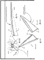
Fig. 1-Fig. 3 has described according to the multiple systems of said inventive embodiment and retaining element or characteristic.
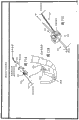
Fig. 4-Fig. 5 has described the multipurpose tool configuration according to said inventive embodiment.
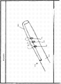
Fig. 6-Figure 17 has described multiple instrument (" the pin ") configuration according to said inventive embodiment.
Figure 18-Figure 19 has described the tensioning anchor configuration according to said inventive embodiment.
Figure 20 to Figure 23 has described according to the operation tool of said inventive embodiment and expansion.
Figure 24 A-Figure 24 D has described extension fixture and technology according to said inventive embodiment.
Figure 25 A-Figure 25 F has described extension fixture and technology according to said inventive embodiment.
Figure 26 A, Figure 26 B have described according to the extension fixture of said inventive embodiment and technology.
Figure 27 has described extension fixture (" expansion ") and the technology according to said inventive embodiment.
Figure 28 A, Figure 28 B and Figure 28 C have described extension fixture and the technology according to said inventive embodiment.
Figure 29 A-Figure 29 D has described extension fixture and technology according to said inventive embodiment.
Figure 30 A-Figure 30 E described according to said inventive embodiment extension fixture and technology.
Figure 31 A-Figure 31 C has described extension fixture and technology according to said inventive embodiment.
Figure 32 A, 32B have described according to the extension fixture of said inventive embodiment and technology.
Figure 33 A-Figure 33 F has described extension fixture and technology according to said inventive embodiment.
Figure 34 A, Figure 34 B, Figure 34 C and Figure 34 E-Figure 34 K have described extension fixture and technology according to said inventive embodiment.
Figure 35 A-Figure 35 E has described extension fixture and technology according to said inventive embodiment.
Figure 36 A-Figure 36 C has described extension fixture and technology according to said inventive embodiment.
Figure 37 A-Figure 37 D has described extension fixture and technology according to said inventive embodiment.
Figure 38 A-Figure 38 B has described extension fixture and technology according to said inventive embodiment.
Figure 39 A, Figure 39 B have described according to the extension fixture of said inventive embodiment and technology.
Figure 40-Figure 55 described according to said inventive embodiment be used for will net the various embodiments on the rumpbone that implant is fixed to the patient.
Figure 58, Figure 59 and Figure 61-Figure 64 described according to said inventive embodiment be used for will net the supravaginal various embodiments that implant is fixed to the patient.
Figure 65-Figure 77 has described the tensile various embodiments that when vaginal apex is fixed on the rumpbone, is used to regulate vaginal apex in rumpbone vagina fixing operation according to said inventive embodiment.
Figure 78-Figure 80 has described the various embodiments that is intended to the transvaginal method that is used for the rumpbone colpopexy on the preceding ligament of rumpbone that net is fixed to according to said inventive embodiment.
Figure 81-Figure 84 has described the various embodiments that is used for net is fixed to the method and apparatus on the vaginal wall according to said inventive embodiment.
Figure 85 A-Figure 85 D has described the combination type elevator/prolapsus supporting arrangement according to said inventive embodiment.
Figure 86-Figure 87 has described the vaginal apex supporting arrangement according to said inventive embodiment.
Figure 88 A, Figure 88 B have described net tensioner and the method according to said inventive embodiment.
Figure 89-Figure 90 has described the elevator supporting arrangement according to said inventive embodiment.
Figure 101-Figure 110 has described the various embodiments according to operation retractor instrument, system or the parts of said inventive embodiment.
Figure 111-Figure 115 has described multiple operation dissecting tool or the system according to said inventive embodiment, and it comprises those that are suitable for using with introducer needle known or that revise.
Figure 116-Figure 120 has described the multiple needle point configuration with the present invention's (for example service aisle, optical channel, lens, sheath, sacculus, cutting blade etc.) use that is suitable for according to said inventive embodiment.
Figure 121 described according to said inventive embodiment be used for through visual observation device or equipment the anchor transvaginal is transported to the optics needle system on the rumpbone.
Figure 122-Figure 129 has described the multiple systems or the method that are used to be convenient to the sacrum fixation of tissue according to said inventive embodiment.
Figure 130-Figure 132 has described multiple rumpbone fixed drive or the system according to said inventive embodiment.
Figure 133-Figure 137 has described the sacrum fixation of tissue net in SCP operation use that is used for according to said inventive embodiment.
Figure 138 has described to have the SCP net of anchor.
Figure 139-Figure 140 has described being used at operation on pelvis (for example, the sacrum tissue fasteners of the net in SCP) according to said inventive embodiment.
Figure 141-Figure 145 has described to be used for the ratchet coil actuator in multiple operation (comprising the SCP operation) use according to said inventive embodiment.
Figure 146-Figure 147 has described the active tissue retractor in transvaginal SCP operation use that is used for according to said inventive embodiment.
The specific embodiment
At the bottom of the basin disorder comprise that masculinity and femininity patient's bladder is outstanding, rectum outstanding, enterocele and uterus and vaginal vault prolapse etc.These disorders stem from the weak or damage of normal pelvic cavity supporting system usually.The modal cause of disease comprises that childbirth, uterus remove, connective tissue defective, long-term heavy physical work and postclimacteric atrophy.
Vaginal vault prolapse is the expansion of vaginal apex, expands to the direction in the vagina outside in some cases.Enterocele is that the peritoneum capsule that wherein contains one section small intestinal extends to the colpocele in the rectum vaginal space.The pelvic cavity of vaginal vault prolapse and enterocele representative challenge form for the doctor is disorderly.
Vaginal vault prolapse is usually outstanding with rectum, bladder is outstanding or enterocele is associated.Be known that through being sewn onto supraspinal ligament and repair vaginal vault prolapse or fornix vaginae is attached on the rumpbone through net or fascia (fascia).The patient who much suffers from vaginal vault prolapse also need perform the operation to correct the stress incontinence of symptomatic or potentiality.
Suspension is to arrange that suspender belt is with operation method stable or supporting neck of bladder or urethra.They are generally used for treating incontinence.There is multiple different suspension.The suspender belt that is used for the pubis vagina operation is different on type of material and anchoring process.In some cases, through abdominal incision and/or vaginal incision suspender belt is arranged in the following of neck of bladder and suspender belt is fixed on the attachment point (for example bone) via the suspension suture line.At United States Patent(USP) No. 5,112, the example of suspension is disclosed in 344, No.5,611,515, No.5,842,478, No.5,860,425, No.5,899,909, No.6,039,686, No.6,042,534 and No.6,110,101.
Rumpbone vagina fixing operation is the operation that is used to provide the fornix vaginae suspention.It can pass through abdominal incision, vaginal incision or carry out through peritoneoscope.Complexity comprises that net infects, compound venous hemorrhage before net erosion, intestinal obstruction, intestinal obstruction and the sacrum.Typically, reparation of abdominal part enterocele and obliteration of cul-de-sac are followed in this operation.
Rumpbone vagina fixing operation relates to vaginal cuff suspention (by means of the implant such as guipure) to sacrum portion anatomic region (the for example anterior longitudinal ligament at rumpbone (bone itself), near sacrum ligament, uterosacral ligament or sacral promontory place).Implant such as polymer fabric can customize or be assembled into given shape meticulously by the doctor.According to some operation, the doctor manually cuts the stitching element of net sheet and net to form this given shape.Bibliographical information the doctor net materials sewed up be multiple T shape article.Referring to Winters et al., Abdominal Sacral Colpopexy and Abdominal Enterocele Repair in the Management of Vaginal Vault Prolapse, Urology 56 (Suppl 6A) (2000): 55-63; (people such as Winter is in last abdominal part rumpbone vagina fixing operation and the reparation of delivering of abdominal part enterocele in the vaginal vault prolapse management of urology 56 (supplementary issue 6A) (2000): 55-63) and Paraiso et al; Laparoscopic Surgery for Enterocele; Vaginal Apex Prolapse and Rectocele, Int Urogynecol J (1999) (people such as Paraiso on international gynecological's urinary system magazine (1999), deliver be used for enterocele, vaginal apex prolapsus and the outstanding laparoscopic surgery of rectum).
In some the SCP operation that also relates to uterectomy; Implant can be attached to hysterectomize with cervix uteri after on the vagina tissue of remaining back, and also be attached on the anatomical structure for example on every side vagina tissue is supported on uterosacral ligament or the rumpbone itself (being the part of sacrum portion anatomical structure) at the rumpbone place or at rumpbone.
As used herein, term " anchor " refers to the structural arbitrary structures that can implant be connected to the pelvic cavity zone nonspecificly.This tissue can be bone, the perhaps soft tissue such as muscle, fascia, ligament, tendon.Anchor can be connected to the structure of this structural any known or the structure or the structure as herein described of following exploitation with implant for being used for; Include but not limited to anchor clamps; Stitching thread, for example from the soft tissue anchor of fixedly tip (self fixating tip), bone anchor, as herein described be used for implant be connected to the regional soft tissue of pelvic cavity or the arbitrary structures on the bone, or the like.
Whole with reference to Fig. 1-Figure 19, the various embodiments that instrument or system 10 and method are shown is to be used for method (for example carrying out the method for rumpbone colpopexy (" SCP ")) use at the treatment pelvic disease.A plurality of parts of system 10 can be made up of polymeric material, metal or the other biological compatibility or acceptable surgical unit material.
Whole with reference to Fig. 1-Fig. 3; SCP point retaining element is configured to generate approximate imitation or duplicates the structure of the uterosacral ligament between the tissue at back vagina tissue (for example, " fornix vaginae ", " vaginal apex ", " vagina top (apical vagina) " or " vaginal cuff ") and sacrum portion anatomic region place.Promptly; Implant (for example for one or more little elasticity organosilicons (or other elastomeric materials); The pipe, bar, the band etc.) 12 or elasticity (solid or hollow) bar can be connected on the vaginal apex (11); And the initial fixation point of uterosacral ligament 9 (be connected near Fig. 1-Fig. 2) sacrum portion anatomic region place (for example, rumpbone (13) locate or near) tissue.Use this configuration of flexible implant that at least two obvious benefits are provided.At first, reduced for the tensile crucial demand (having reduced thus) of regulating of vaginal apex doctor's dependency and comfort level/operative complications of patient.Secondly, through using the elastomeric material (it moves with the mode similar with natural anatomical structure and activity is reacted) of flexible implant 12, the dissection body of natural imitation or the elastic property of structure.
The elastomeric material that is used for implant 12 can allow that flexible implant stretches and adapt to multiple implant technology and patient's movable and motion.The elastomeric material that is used for this flexible implant embodiment can take to have the arbitrary form or the shape of overall flexibility configuration.Elastomeric material can be natural or synthetic polymeric material, and it provides the elasticity of imitation vagina tissue or uterosacral ligament tissue to flexible implant.For example, the flexible implant that has less than the spring rate of 25 pounds/inch (for example, from 2 pounds/inch to 25 pounds/inch or from 5 pounds/inch to 20 pounds/inch) can be ideal goal, and also conception has other various configurations and flexible grade simultaneously.The example of suitable elastic materials possibly comprise silicone rubber, natural or synthetic rubber, polyolefin, comprises the implant of mechanical elasticity spring, or the like.
Flexible implant (for example can have tissue that from fornix vaginae or other back vagina tissue arrives at sacrum area; Sacral promontory, fascia, near ligament (sacrum ligament, uterosacral ligament, anterior longitudinal ligament) or fascia) length; And the tensioning degree (for example, owing to stretch) that on flexible implant, has expectation.Flexible implant can be for than planar in form or material, for example elongate resilient net, bar or band or tubulose.Implant can be processed by the unitary elasticity material, and perhaps implant can be the set composite that is made up of a plurality of parts (one of them or all be elastic).
The single concrete example of flexible implant has been shown among Fig. 2.Flexible implant 12 is the elastomeric material between back vagina tissue 11 and sacrum portion anatomic region (not shown).The distal portion that anchor 7 can be used in flexible implant 12 is fixed on sacrum portion anatomic region place.Close end can be attached on the vaginal apex 11 through any useful method.
As an example; Fig. 3 illustrates the flexible implant 12 of the form that is the elastic polymer tube with two opposed ends; First (near-end or preceding) end structure is to be engaged in or to be connected to be positioned at fornix vaginae place or near tissue, and second (far-end or back) end structure is to be engaged in or to be connected to the tissue that is positioned at sacrum portion anatomic region place.First end can for example be connected on the vagina tissue by means of stitching thread, U-shaped spare (staple), biological adhesive, anchor etc. directly or indirectly.For example, first end can connect via intermediate structure (for example having the agnail anchor (15) that is configured to be coupled to the barbed ends in the pipe 12); Opposite (near-end) end of agnail anchor (15) can be configured to be fixed on the vagina tissue directly or indirectly through the anchor of any desired or other devices (for example anchor clamps, fixedly tip, soft tissue anchor or for example anchor as herein described etc.) certainly.The second end of tubulose flexible implant 12 can be for example be connected to the tissue in sacrum portion zone by means of stitching thread, U-shaped spare, biological adhesive or at this paper or other local described another anchors directly or indirectly, perhaps can be fixed to the regional tissue of sacrum portion through other desired results arbitrarily (for example anchor clamps, fixedly tip, soft tissue anchor, bone anchor etc.) certainly.
According to Fig. 4 and the illustrated multi-purpose tool of Fig. 5, solve and eliminated usually perform the operation relevant visual observation and fixed challenge with transvaginal SCP.Promptly; Multi-purpose tool 14 is set up and can be used in one or more in the combinations function: (for example dissect; Through cut open art or any device other such as blade, hydrolysis), passivity dissects, observes (promptly; " visual observation "), illuminate, FLUID TRANSPORTATION, flushing, suction and anchor (bone anchor, the soft tissue anchor is for example from fixedly tip, stitching thread etc.) is arranged in the desired destination tissue.Fig. 4 is the side isometric view of instrument 14, and Fig. 5 is the end-view that points to 16 places, tip.Alternatively, tip 16 can pivot and reach 90 degree, perhaps rotates alternatively or alternatively, to advance around critical anatomical structures.The doctor can lean on a hands in once transmission, to accomplish a plurality of tasks by tool using 14, and keeps another hands freedom to accomplish other parts or the step of SCP operation.Tissue injury can be reduced and overall ability visual and that deal with problems is enhanced.
Fig. 5 is just (end) view of tool tip 16, has described a plurality of functions of instrument 14 and the example combinations of structure, for example, and light source (16a); The lens (16b) that are used for photographic head or other optical observation functions; Fluid (for example, liquid) distributes port, for example, " irrigation ports " that be used for distribution of gas, water, saline or other liquid or gaseous fluid (16c); Suction ports (16d), it is used for arranging that at tool tip 16 places vacuum or suction are for example to remove the liquid of gaseous fluid; And anchor port (16e); It is used to handle anchor and anchor is arranged in the tissue place or tissue in pelvic cavity zone; This anchor is that perhaps as described herein being used for is fixed to structural other anchors or fastening or retaining element arbitrarily with implant such as stitching thread, anchor clamps, sewing needle, the fixing arbitrary form tip, the bone anchor certainly.In these characteristics of tip 16 each is communicated with the close end of device 14 through cavity, optics connector, mechanical fastener or electronics connector (if necessary).Close end (referring to Fig. 4 and Figure 14) can comprise the one or more handles that are used for by doctor or the manipulation of other user, and can comprise additionally that one or more connectors are to allow operation or the manipulation that is communicated with and allows each structure, port or function portion with each structure, port and the function portion at 16 places in the tip.
In various embodiment, suction ports (16d) can be shared identical distal tip 16 holes or opening features with irrigation ports (16c).
Light source 16a can be any light source in the light source at the distal portion that is positioned at instrument 14 or 16 places, tip.Light source 16a can be connected on the light source (bulb, light emitting diode (LED), LCD etc.) that is positioned at the close end place through optical fiber, perhaps can comprise the instrument of being positioned at 14 remote end part be wired to bulb or LED or the LCD light source on the close end.The 16b of overview function portion can be for being arranged on 16b place, tip and the miniature electric photographic head close end electric connection; Perhaps can comprise lens and optical fiber; Wherein optic fibre extension passes the axle of instrument 14 and has (far-end) end that is positioned at 16 places, tip and another (near-end) end that is positioned at the close end place of instrument 14, and close end is communicated with electro-photographic head vision.Light source (16a) and overview function portion (16b) can share or not share and be positioned at the same port on the tip 16.
The pivot of tip 16 can change in scope and can surpass 90 degree, and also can on a plurality of dimensions, pivot, and perhaps can rotate alternatively.In addition, anchor port (16e) can or be arranged in the arbitrary portion of tip 16 or is arranged on the position along adjacent shaft for arbitrary configuration.
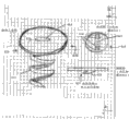
Fig. 6-Figure 17 illustrates multiple other embodiment of apparatus and method, comprising: needle system 20, and it comprises the instrument with handle 19; Needle shaft 23, it comprises that optional observation (visual observation or optics) and illumination (illuminating) characteristic throw light on and observe the pelvic cavity position that is used to arrange implant or anchor being used to; With and related methods.
Conventional pelvic implant is installed operation (for example, SCP operation) and can be carried out through the abdominal part opening or through peritoneoscope.Thus, need special technical ability and equipment should perform the operation to accomplish efficiently.And generated abdominal wound.Said multi-purpose tool can provide Minimally Invasive Surgery and not have the perforation of abdominal wound or potential organ or dissect, have useful distal portion functional (for example anchoring is functional, observation and illumination functions property, turn to, aspirate, dissection, anchor are carried, implant carries and FLUID TRANSPORTATION).Observe and the implant means of delivery of illumination functions portion by means of having, provide to interior tissue know visual observation with the needle passageway that is used for implant and anchoring for example to rumpbone.The doctor can be through direct observation and (vision ground) guiding implant means of delivery is (promptly optically; " pin ") distal portion or the axle; Potential deathtrap is discerned on vision ground, and pin is guided or redirect to the desired target tissue position that is used to arrange anchor or implant.For the doctor provides cognitive faster curve transmitting pin safely by means of optical viewer and optical observation, and the knowledge of the use of optical viewer in operation is applied in the operation and is of value to operation.
Exemplary needle system 20 (having optics and visual performance property) can comprise instrument 14; Instrument 14 comprises slender axles; This comprises one or more that separate or integral type " axle " structure and anchor interface structure 22d, and instrument 14 can be made up of flexibility or rigidity biocompatible materials (for example rigidity or flexible polymer, rustless steel (high strength and high elastic modulus) etc.).Axle or shaft assembly can have than minor diameter, but have enough rigidity with admit of with and the passing through and lead of safety.
With reference to Fig. 6, Fig. 7 and Fig. 8, one or more anchors 22 can be configured to not only be fixed to the tissue at sacrum portion anatomic region place, and make light can get in observation or the illumination feature of insertion instrument or leave this characteristic.For example, anchor 22 can comprise hole, lens or be used for the opening that light passes through, and can be made up of the transparent or semitransparent biocompatible materials that is suitable for implanting, and also allows the vision illumination and observe to be used for the intravital guiding the patient.For example, as at United States Patent(USP) No. 7,500,945, No.7; 407,480, No.7,351,197, No.7; 347,812, No.7,303,525, No.7; 025,063, No.6,691,711, No.6; 648,921 and No.6,612,977, disclosed various anchors can be adopted by the present invention with similar attachment arrangement, instrument, system and method among the open No.WO 2008/057261 of international monopoly and No.WO 2007/097994 and the open No.2002/151762 of United States Patent (USP) and the No.2002/147382.Therefore, above-mentioned disclosed whole disclosures are incorporated this paper into fully through the mode of reference.
In this embodiment, system 20 can comprise the slender axles of multi-purpose tool with the optical fiber source that is integrated into wherein and imaging optical fiber bundle (for example, as Fig. 9 and Figure 13-shown in Figure 17).System 20 can comprise the characteristic of being convenient to organize anchoring through the conveying of one or more anchors 22 (for example, like Fig. 6, Fig. 7 and Fig. 8 diagram).Fig. 6 shows soft tissue anchor (for example, " certainly fixedly tip "), and it comprises the internal channel (or " needle interface " 22a) that extends to distal portion (22c) from close end (22b) (being connected on the stitching thread 23).Passage (or " needle interface ") 22a can be suitable for the anchor interface surface of fitted shaft or the distal portion at anchor junction surface; Thereby allow that alternatively light transmits between the distal portion of anchor interface, to allow and illuminate and optical observation tissue and operative site by means of illumination and overview function portion.Extension 26 can be allowed the secure placement of anchor 22 at the tissue place, thereby prevents moving along backward directions after anchor 22 being pushed in the tissue.Anchor 22 can be included in the light guide features (25) at its place, tip alternatively being directed to just by the tissue of visual observation through anchor 22 from the light of optical fiber cable end.
With reference to Fig. 9; (system 20) instrument 14 can comprise illumination and overview function portion; Comprise one or more in following: light source, lens, working cavity, (comprise handle at close end; Towards the operator) and distal portion (towards the patient) between the optical fiber (21a is restrainted in for example, primary beam 21b and imaging (" observation ")) that extends and be positioned at the close end place or be connected to photographic head or other recording apparatus (not shown) on the close end.Like diagram, imaging optical fiber bundle 21b can comprise like expectation and arranging or useful multifiber optical cable, and wherein optical fiber cable end (distal portion) is positioned at the remote end part of instrument 14 and the second end (close end) is positioned at the close end place of instrument 14.Imaging optical fiber bundle 21a can allow the tissue that observation (vision is watched) is illuminated through illumination functions portion.In one arrangement, be provided with into video beam 21a and primary beam 21b, wherein become video beam 21a to be positioned at the center, and primary beam 21b circumferentially surround into video beam 21a.In different layouts, one-tenth video beam 21a can be positioned at primary beam 21b side or additionally be provided with independently with primary beam 21b.Thus, light source and primary beam (21b) can with become video beam 21a not break away from the whole or separate to watch organizational structure to allow having dazzle or illumination to leak under the situation in the imaging optical fiber bundle 21a vision.Alternatively, become video beam 21a can be positioned at the inside of axle, at the cavity (not shown) and have the sealing lens that are positioned at remote end part with the bundle 21a that prevents to form images in intra-operative contact patient's tissue or body fluid and the repeated use of allowing into video beam 21a.
Still with reference to Fig. 9, be positioned at axle remote end part be to be used for the anchor interface characteristics 22d that engages with passage or " needle interface " characteristic 22a of anchor 22 (not shown).Anchor interface characteristics 22d can with imaging (" observations ") bundle 21a and primary beam 21b in one or two be communicated with so that light and image can the tissue adjacent with tip 22 with become video beam 21a and primary beam 21b in each between transmission pass tip 22.Alternatively, axle (that is, " pin ") possibly comprise along the primary beam 21b of pin (length along pin is passed cavity) with becomes video beam 21a, and the hole or the opening that are positioned at sidepiece or the place, end of pin can be allowed and thrown light on and observation.Observation can be carried out through distal portion lens or opening.Illumination can be through side opening or distal portion hole, through the hole in the anchor 22 or carry out by means of transparent or semitransparent anchor 22.
Anchor interface characteristics 22d can be arranged in the remote end part of independent axes structure of the axle (23) (for example being arranged on vertical cavity or passage) of the instrument of being arranged on 14 alternatively.This allows that the independent axes structure that comprises anchor interface characteristics 22b can move and can (mechanism at the close end place through being arranged on instrument 14) distad extends and shrink from the distal portion of axle 23 in axle 23.Alternatively, anchor interface 22d can comprise that ratchet or other mechanisms are to allow that anchor is through distad extending and shrinking and optionally engage and break away to be used for the layout at tissue.
Can along whole length of axle 23 or distal length comprise optional sheath 24 with cover with protective tissue anchor (22) till deployment from axle 23, shown in Figure 10-Figure 12.Sheath (24) can be for covering the simple protection department of axle on (23) keeping and to protect anchor and allow that fluid flushing (by means of FLUID TRANSPORTATION and optional pumping function) cuts open to be used for hydrolysis to tissue site, perhaps washes optics (observation) lens or wash the anchor position to allow the better visual observation under the situation that blood, fat or its hetero-organization or fluid exist.Alternatively or alternatively, sheath 24 can also be through comprising that one or more optical fiber cable that is used for illumination or imaging (observations) comprise illumination or (observation) function that forms images.For example, sheath 24 possibly comprise that optical fiber cavity or the ccontaining characteristic of other optical fiber to keep optical fiber cable and light is directed on the anchor or directly is directed to tissue, perhaps allow the imaging or the observation of tissue.
Also alternatively or alternatively, sheath 24 can comprise other function portions, for example can be used in the irrigation ports of surgical site irrigation, to allow that hydrolysis is cutd open and to allow visual observation better through flushing implant site and the lens that are used for imaging optical fiber bundle.In addition, sheath 24 can take to have passage, the multiple configuration of port, integral fibre-optic optical cable, pipe etc.Referring to Figure 10, Figure 11 and Figure 12.
In Figure 10, sheath 24 can be simple aggregation thing rigid pipe, flexible pipe or the semi-rigid pipe with two open ends on the axle of the instrument of being assembled to 14.Be called among the open No.2010/0274074 of the pending trial U.S. of " treatment and related tool and implant at the bottom of the basin " description and this sheath has been described in applicant's name, the full content of this application is incorporated this paper into through the mode of reference.
Figure 11 shows the sheath 24 similar with the sheath of Figure 10 24, but additionally comprises the cavity 24a that is used for lighting fiber (being lighting fiber 24a alternatively).As shown in, cavity or lighting fiber 24a can be in the outside of axle 24 (left figure) or one in the sidewall (right figure) of axle 24.
Figure 12 shows the sheath 24 similar with the sheath of Figure 10 24, but additionally comprises cavity 24a that is used for lighting fiber (being lighting fiber 24a alternatively) and the cavity 24b that is used for imaging fibre (being imaging fibre 24b alternatively).As shown in, each cavity or lighting fiber can be in the outside of axle 24 (left figure) or one in the sidewall (right figure) of axle 24.
Shown in Figure 15-Figure 17; Customization or adaptive sheath 24 can be provided with standardization incontinence or prolapsus repair needle system to comprise necessary cavity (as the part of sheath 24) thus provide like described multifunctionality (for example, central imaging fibre cavity and lighting fiber cavity).In this embodiment, instrument 14 can comprise axle, and this can be for having the rigid needle 23 of the standardization solid metal that customizes sheath, and the customization sheath comprises three cavitys: with the center cavity of holding pin; The imaging fibre cavity that holds the optical fiber cable of (observation) tissue location that is used for forming images; And the lighting fiber cavity that holds the optical fiber cable that is used to illuminate tissue location.Sheath 24 can be (for example, being processed by the polyolefin such as polyethylene or polypropylene) of flexibility and can be in compliance with the shape of pin.Pin can be bent into required form by the doctor at intra-operative alternatively for ductility or inflexible.When comparing, can improve the cost and easy property that use and make for example poly squash type multi-cavity body sheath with other more complicated axle configurations that are used for multi-purpose tool.(make the bending of multi-cavity body sheath that inner chamber body is shunk during manufacture.) be used to throw light on or the optical fiber cable that is used to observe can be arranged in polymer jacket 24 outer surface, be arranged in polymer jacket 24 the inner surface place, or be arranged in the cavity or be integral along the length and the sidewall of polymer jacket 24.Lens can be arranged in one or two or more the end of multifiber optical cable sentence through the cavity that optical fiber is slipped into and skid off sheath and make optical fiber (for example, imaging fibre) can be repeated to use.Alternatively, one or two in imaging fibre and illumination (illuminating) optical fiber can be attached on the sheath and can abandon together in company with sheath.The needle point that extends through (master) inner chamber body of sheath can comprise and is used for the distal portion that engages with anchor (for example from fixedly tip), perhaps can comprise the hole that extends to the close end that is used for stitching thread or flushing or suction channel or port.
The embodiment of Figure 18-Figure 19 can comprise tensioning or the securable anchor 30 that is used in pelvic cavity treatment (for example SCP operation) use.Anchor 30 can be taked as known, disclosed or incorporate various designs and the configuration of this paper into.Particularly; The pulley system 32 that comprises eyelet 34 (for example, on the anchor 30) and stitching thread 36 can be used with time on the rumpbone that is attached to sacrum portion structure at anchor 30 or another part and anchor 30 is provided with respect to the tensioning or the adjusting of the implant that is attached to stitching thread on 36.Thus, the end of stitching thread 36 can or be attached on the vaginal apex through the implant bind, and sutural remainder passes the eyelet 34 of anchor 30 and the outside that warp per vaginam continues to advance to health.This allows the tension force and the supporting of dynamic adjustments vaginal apex.Multiple known material can be used in a plurality of parts of this embodiment of structure, comprises Merlon, polypropylene, polyethylene, suture material or the like.
Whole with reference to Figure 20-Figure 24, illustrate various embodiments with slender axles and operation tool 50 of pipe 52.The instrument 50 that comprises axle is configured to use so that manage 52 to the guiding of operative site or anatomical structure (for example sacrum portion anatomic region) with pass through at intra-operative usually.Instrument 50 allows that will manage 52 through otch is arranged among the patient so that manage 52 approaching to internal surgical site can be provided, and for example is used to arrange surgery implant.Pipe 52 can be used in the operation articles or other objects (for example, sharp keen object) (through managing 52) under the situation of repeatedly attempting that needn't carry out zone from the otch to the anatomical object that make such as instrument, stitching thread, implant or its parts and advances to internal surgical site.Alternatively, operation tool 50, pipe 52 or both can comprise the function portion that is used to illuminate or observes operative site be used for dissecting, flushing, layout anchor etc., described as this paper for multi-purpose tool.For example, if operation tool 50, pipe 52 or both parts are plastics or polymer optical material, then light can pass this transmission of materials to the distal portion that is positioned at surgical site from close end.
In certain embodiments, pipe 52 can be used near sex pelvic cavity anatomical structure, especially transvaginal near the female pelvic cavity anatomical structure, thus organizing near pelvic cavity zone, back for example to carry out the SCP operation.Pipe 52 can have allows thisly near length when the pipe transvaginal is arranged, for example allows the length of the distal portion of pipe near pelvic tissue when vaginal orifice extends to the position of patient outside when the close end of pipe passes.The close end of pipe keeps patient's outside during use so that doctor or other user can be approaching with the manipulation close end and through managing near the operative site that is positioned at remote end part.Between the exemplary lengths between close end and the distal portion can scope be between 13 centimetres to 18 centimetres, especially in female patient, uses with the position (for example sacrum portion anatomic region) of transvaginal near pelvic cavity zone, back.
The slender axles of instrument and the diameter of tube portion can be used in allows insertion and placement tool under the situation that reduces to damage.Alternatively, as said in other places of this paper, it is approaching to allow the increase and the expansion ground of the tissue that is positioned at surgical site that the diameter of pipe can change (for example through expansion after pipe being arranged in patient's body).
Alternatively; Instrument (for example can comprise one or more functional characters in the instrument remote end part or in the remote end part of pipe or in the remote end part of axle; Like the previous described operation tool 14 that is used for of this paper), these characteristics comprise make instrument 50 or manage 52 can be used in execution such as dissect (use the machinery of sharp knife blade to dissect or hydrolysis is cutd open), passivity dissect, observe (visual observation) operative site, illuminate operative site, the FLUID TRANSPORTATION of surgical site, the flushing of surgical site, in surgical site suction, axle or manage or the two turning to property and the function that anchor (bone anchor, such as fixedly the soft tissue anchor the tip, stitching thread etc.) certainly is arranged in the desired target tissue of surgical site and so on of distal portion.
The various systems that this paper details, instrument and method design are used for using together with a lot of known implants and repair system (for example, being used for masculinity and femininity), characteristic and method, are included in United States Patent(USP) No. 7,500; 945, No.7,407,480, No.7,351; 197, No.7,347,812, No.7,303; 525, No.7,025,063, No.6; 691,711, No.6,648; 921 and No.6,612,977, those disclosed among international patent publications No.WO 2008/057261, No.WO 2007/097994, No.WO2007/149348 and U.S. Patent Publication No.2002/151762, No.2010-0174134, No.2010-0298630 and the No.2002/147382.Therefore, above-mentioned disclosed full content is incorporated this paper into through the mode of reference.
Figure 20 shows and arranges the single example be used near the instrument of " pipe " 52 of the operative site of pelvic cavity location.Instrument 50 among Figure 20 can comprise guiding distal portion 54, axle 56 (for example, the inboard of pipe 52), pipe 52 (for example, being arranged on the place, outside of axle 56) and handle 58.In addition, the cutting mechanism 60 of spring, spring activation, mechanical activation or other types can be included in the optional position of instrument 50, so that cutting (being used for dissecting) and/or activation distal portion 54 generate little otch with the anatomical structure the patient.When cutting and guiding tool 50 pass the target area of organizing path (for example, transvaginal in female patient) to arrive tissue, manage 52 and can separate with axle 56.Can remove handle 58 from the patient and stay pipe 52 (that is, can during the operation placement process, be held in place) with axle 56 so that qualification path or the passage that arrives operative region (position) to be provided, thereby be used near operative region (position).In the concrete grammar of the SCP of transvaginal ground female anatomy treatment; Pipe 52 is arranged as that the vaginal orifice, the pipe that make close end extend the patient extend through vagina and vaginal incision and distal portion is arranged on the place, rear portion in patient's pelvic cavity zone; For example, near sacrum portion anatomic region.
Shown in Figure 21, Figure 22 and Figure 23, comprise that pipe 52 instrument 50 can take multiple different shape and size configuration and can advance via dissection and pass vagina with vaginal orifice and get near the regional rear portion (rumpbone) of pelvic cavity.Instrument 50 and pipe 52 can be used in and provide near the path at multiple other anatomical structures or position or port path and without departing from the spirit and scope of the present invention.
With with the optional embodiment of the device that uses of pipe 54 similar modes (for example; " expansion ", " retractor " or " pipe ") also be contemplated that the otch that is used for through the sex patient interior tissue near the pelvic cavity zone; For example, tissue retractor is used for the rear region of transvaginal near the female pelvic cavity anatomical structure.Can according to the one or more uses in the method as herein described these the pipe 54 with all the other in any; To be used to arrange implant, for example use any or a plurality of SCP operations in implant as herein described, insertion instrument, multi-purpose tool, the anchor etc. with the supporting pelvic tissue.
Multiple such embodiment of " expansion " describes hereinafter; And can have following overall structure and performance characteristic: its make one or more flexibilities, inflexible or semirigid far-end retract structure can closed, compress or reduce size or swedged state under introducing and (for example pass otch; Vaginal incision); Be moved subsequently, assemble or expand and promote will organize to sidepiece with enlarged cross section size or correlation space or opening, thus in the pelvic cavity zone span and generate the path in pelvic cavity zone and near the pelvic cavity anatomical structure of expectation.When far-end retracts structure when being in its configuration that reduces size, the preferred size of device can comprise scope be from 1 centimetre to 5 centimetres (for example from 2 centimetres to 4 centimetres) (these are referred to herein as diameter range d
1) sectional dimension (width or the diameter that for example, are associated) with the opening of length along device.When far-end retracts structure and opens wide, do not compress, expands or during assembling etc.; The preferred size that joins with these structurally associateds (width or the diameter that for example, are associated) with opening along the length of device can scope for from 2 centimetres to 10 centimetres (for example from 3 centimetres to 7 centimetres) (these are referred to herein as diameter range d
2).Also common; These structures (pipe, retractor, or the like) can comprise the length dimension (from the close end to the distal portion) of expectation, and this size can be chosen for specific anatomical structure (sex) and operation (repair or the like preceding reparation, back) and work.The length of the concrete structure that uses in the transvaginal method of pelvic disease after treatment (for example, SCP operation) (pipe, retractor or the like) can be enough to make distal portion can arrive at sacrum portion anatomic region when close end remains on the vaginal orifice place or remain on the outside of vaginal orifice.Relevant size is this device " working depth ", working depth be device when being mounted between the distal portion of device and the distance between the vaginal orifice, and it can be useful or desired size arbitrarily, for example from 13 centimetres to 18 centimetres.Device is away from the distance that patient's proximad extends vaginal orifice and preferably minimizes.Still with reference to these use of device in the transvaginal therapy method; Another relevant " work space " size that is of a size of; " work space " is of a size of the lateral dimension of the opening at the close end place that is positioned at device, diameter for example, and this diameter can scope be from 3 centimetres to 8 centimetres preferably; In the transvaginal method, this is the about diameter through the unlimited vaginal orifice of the close end maintenance of device.
Figure 24 A-Figure 24 D illustrates compression tube expansion and technology according to an embodiment of the invention.These figure illustrate the type of retractor of expansible " pipe " (100) and are the specific embodiment of the independently inserter device (stretching device) of axle (104) form, and axle (104) can be arranged in the pipe 100 and with assistance pipe is arranged in the sex patient body.Axle-pipe configurational energy is enough in allows pipe at patient's body intramedullary expansion, thereby produces passage to allow near patient's internal anatomy pelvic cavity zone for example through pipe.The compression tube notion uses the pressure that is generated by syringe or other devices to make little elastic tube (being similar to catheter deployment system, still bigger) expansion.Because the flexibility of elastic tube, outer tube can insert and expansion before or after rigid member is removed subsequently via rigid member (for example, pipe, bar, introducer device, or other more inflexible inserter devices that vaginal canal is opened wide).After the expansion of pipe, another rigidity substitutes on the pipe that pipe can be arranged in expansion so that the open type work space to pelvic cavity anatomical structure (for example rumpbone) to be provided, and can remove the pipe of expansion.Pipe can be designed to the working depth and the work space that provide as described herein.
With reference to Figure 24 A, distensible tube 100 comprises distal portion 102 and close end 106.Distensible tube 100 also comprises opening and the continuous passage that between close end and distal portion, extends or the opening at each place in close end and distal portion.The structure of pipe (i.e. the sidewall of pipe) comprises single space or a plurality of space; This space forms the inner space of one or more sacculus or encapsulation, is adapted to this inner space (not shown) that makes it possible to fill fluid and causes managing 100 and expand with the mode of the size of the opening that increases distal portion and close end place with the diameter that increases pipe.Figure 24 A and Figure 24 B show and are in the pipe that loosens, shrinks under (reducing diameter) state.The diameter that is in the pipe under this contraction state can be for being arranged in the intravital diameter of patient by means of axle 104 with collapsible tube effective (for example, having the patient's damage that reduces) like what expect usually.Preferred diameter can scope be from 1 centimetre to 5 centimetres, and for example (these are referred to herein as diameter range d from 2 centimetres to 4 centimetres
1).This diameter approximates the external diameter of axle 104 greatly.
Still with reference to Figure 24 A, insertion instrument 104 can be used in pipe 100 is arranged in patient's body to be used for operation.Instrument 104 can comprise that axle, pin or the bar 104 (" axle " 104) of elongated flexible, inflexible, semirigid or ductility are with support column 100.In use; Be arranged in axle 104 outer surface through managing 100; It is interior (for example that distal portion 102 can be inserted into patient's body; Transvaginal is in the female subjects), manage simultaneously 100 be in contraction, under the non-expansion condition to cause distal portion 102 to be arranged near desirable tissue position (for example be arranged on sacrum portion anatomic region place or).Before or after removing axle 104, pressure fluid (for example, liquid such as water, saline or air or gas) can be introduced in pipe 100 the inner space with filling and this space of pressurizeing.Under contraction state, pipe 100 can comprise fold or folding part alternatively, and it will become corrugationless or unfolded when pipe 100 is expanded to expansion state.Alternatively, pipe 100 elastomeric material that can between contraction state and expansion state, change for extension.
Fluid can be introduced the inner space through any useful method and device the syringe 108 of the port one that is arranged in close end 106 10 places (for example by means of).Fluidic introducing will make pipe expand to the expansion state shown in Figure 24 C and Figure 24 D, have and can be the expansion diameter of any desired diameter, for example scope be from 2 centimetres to 10 centimetres (for example from 3 centimetres to 7 centimetres) (these are referred to herein as diameter range d
2) diameter.
The pipe 100 of expansion has intensity and horizontal and vertical rigidity, and said intensity and horizontal and vertical rigidity are enough to make pipe 100 to generate opening in the tissue in the pelvic cavity zone through expansion tissue (for example when transvaginal is arranged).If expectation can comprise optional machinery enhancing portion along the length or the periphery of managing 100.When in such as the transvaginal of SCP operation (combining with instrument, multi-purpose tool, implant, scalable implant, anchor or other devices described herein or method alternatively), using, use axle 104 will manage 100 insertion intravaginal and distal portion 102 is arranged near the rumpbone.Patient's tissue will shrink around pipe 100.Pipe 100 is pressurized subsequently to force tissue to center on pipe 100 expansions of diameter increase and to open wide to generate the path to the regional rear portion of pelvic cavity, for example obtains the path to sacrum portion anatomic region.Alternatively; Manage 100 after patient's body intramedullary expansion; Another pipe that for example has great machinery intensity more (for example; Pipe as described herein or retractor or expansion, and provide like described working depth and work space) can be arranged on the intravital convergent divergent channel of patient so that the open type path to pelvic cavity anatomical structure (for example sacrum portion anatomic region) to be provided, and convergent divergent channel 100 can be removed.
A lot of other embodiment (for example managing 100) of pipe can be useful and as using saidly, but tubulate different structure of tool and characteristic.The example of these other embodiment is described and for example is shown among Figure 25 to Figure 39 and Figure 101 to Figure 110 at this paper.In the device of these diagrams and description (being called " expansion ", " pipe " or " retractor " interchangeably) any can be inserted in the operative incision (for example transvaginal otch) and tissue expander be used or useful with the method near the expectation anatomical structure through installing.In order to carry out the operation of SCP or other transvaginal, pipe or retractor can be for example with expansion not, the contraction state transvaginal arranges.This structure can be expanded (alternatively through assembling) subsequently when transvaginal is in place, to generate the path of the anatomical structure (the for example rear portion in pelvic cavity zone) to expectation, for example obtain the path to sacrum portion anatomic region.The doctor can carry out operation by means of this path, and this path provides the work space that is used for pelvic cavity anatomical structure (for example rumpbone).This method can also relate to instrument as herein described, multi-purpose tool, implant, scalable implant, anchor or other devices or method alternatively.Allow that optional feature and the structure (for example, optical fiber) of observing or illuminating remote end part can be incorporated in these types of devices any.For example, if the structure member of device is processed by plastics or polymer optical material, then light can pass this transmission of materials to the distal portion that is positioned at surgical site from close end.Alternatively, optical fiber cable can be incorporated in the segment length (extend to distal portion or extend towards distal portion from close end) of device, so that light can be transferred to distal portion from close end, perhaps makes image be transferred to close end from distal portion.Light can produce and from distal portion, send alternatively.
With reference to Figure 25 A-Figure 25 F, show self expandable Nitinol support 120, deployment according to an embodiment of the invention and manage (for example, conduit) 122 and manual operation formula retractor device 124, reach technology.Self expandable (for example, Nitinol) support can use self expandable (expansible) intensity of Nitinol or phase metallike or polymeric material.Support 120 is biased to opening (not shrink or " deployment " state), and support 120 has the length that reduces and the diameter (d of increase
2), and can shrink and extend to and have more length and reduce diameter (d
1) not deployable state.Can make and do not shrink (deployments) support and shrink (closure) and extend through transverse pressure being applied on the rack surface end or the position of the length of support (for example along).The support that is used for using with method as herein described can be set (biasing) and be expansion, and in the time will disposing pipe (122) and from external diameter and outer surface, remove self expandable.Support can be designed to the working depth and the work space that provide as described herein.
In use, be arranged on the contraction support 120 disposed in pipe 122 (referring to Figure 25 A) for example transvaginal be arranged in patient's body, wherein distal portion is arranged near the anatomic region (for example sacrum portion anatomic region) of expectation.Deployment pipe 122 can be removed and support 120 arrives expansion diameter (for example, d at patient's body intramedullary expansion
2), thereby be created on the opening in the inside of expandable stent 120 at (for example, between vaginal orifice and sacrum portion anatomic region) between the close end and distal portion of support 120.Length is allowed the path that is used to perform the operation to opening.Support 120 has can expand in the tissue in pelvic cavity zone, to generate the intensity and the horizontal and vertical rigidity of opening through the expansion tissue pipe.Operation (for example, SCP) can be carried out near the pelvic cavity anatomical structure through the space (passage or opening) that is generated by expandable stent.After operation, support can be removed, and shrinks alternatively and is removed subsequently.
Alternatively, support 120 can shrink through support is located to insert to dispose in the pipe 122 at close end (the patient outside) again.Deployment pipe 122 can be arranged in the close end place and distad advance along the length of support 120, thereby causes support 120 to shrink.Alternatively, support 120 can comprise rope (for example, stitching thread etc.) 124, and rope 124 can for example be attached on the support 120 at the close end place.Alternatively, dispose in the pipe 122 for support 120 is inserted into again, rope 124 can be along proximal direction (being away from the patient) pulling, disposes pipe 122 simultaneously and advances along distal direction (towards the patient).This step combination can be allowed in the initial deployment pipe 122 of support 120 withdrawal/compression and back effectively.
Another option means that is used for manually expansion and contraction support 120 can assemble with " the manual operation formula retractor " 128 on the end that pressure is applied to support for the end around support 120.This manual operation retractor can comprise: with the contacted jaw in the end of support 120, the handle of control jaw size and the quick connector that can locate to lock manual operation formula retractor at an arbitrary position.Referring to Figure 25 E and Figure 25 F.
Figure 26 A and Figure 26 B show expandable stent 140 and technology according to an embodiment of the invention.Expandable stent 140 is similar to the support 120 of Figure 25 A-Figure 25 F on size and intensity.Alternatively, support 140 comprises shape memory characteristics.For example, support 140 can be stable (not biasing), and can before using, be present in non-deployment (contraction) state, for example diameter d
1The place.Such as expansible conduit, dispose in the inside that deployment devices pipe or the similar structure (not shown) can be arranged in support 140 and be used for support 140 for example transvaginal be arranged in the anatomical structure position of expectation.Deployment devices can be subsequently at support 140 intramedullary expansions, thus cause support 140 at patient's body intramedullary expansion to expansion state.Deployment devices can be compressed and be removed subsequently support is stayed the expansion state of expectation.Optional expansion mode can be the convergent object or the introducer of in support 140 undesirably is arranged on patient's body, advancing to distal portion from close end afterwards.Shape memory characteristics makes support 140 can be suitable for and maintain the intravital expansion diameter of patient (for example, d
2), thereby for example between vaginal orifice and sacrum portion anatomic region, generate the space that is positioned at expandable stent 140 inside.The path that is used to perform the operation is allowed in this space.Support 140 has allows that the intravital expansion of patient is to remain on intensity, horizontal and vertical rigidity and the shape memory characteristic that in the tissue in sacrum portion zone, generates opening under the expansion condition through the expansion tissue and with tissue.
With reference to Figure 27, showing according to an embodiment of the invention, ductility retracts system and device and technology.The ductility system of retracting can be suitable for the various existing framework that retracts system and device (for example in vagina operation (for example, independently star retractor systems), using).New equipment will be referred to one or more ductility retractor arms 152, and arm 152 directly is attached on the retractor frame 150 and extends in the operative incision (for example vaginal incision) and arrives the path that potential solution cuts open structure (for example anchor position) to generate.The retractor systems of retractor arm of being ductile can be designed to the diameter d that provides as described herein
2, working depth and work space.
Still with reference to Figure 27, during use, framework 150 can be arranged as allows near vaginal orifice and is arranged in the patient outside.One or more retractor arms 152 can be connected on the framework 150 and through vaginal orifice, alternatively through the guide slits introducing, move to subsequently in the position of allowing near back pelvic cavity anatomic region (for example sacrum portion anatomic region).Each arm can be for ductility, and alternatively, additionally or alternatively for flexible and can lock onto in the rigid location.When in transvaginal operation (for example SCP), using, retractor arm 152 is inserted into intravaginal and distal portion is arranged near rear positions place (for example the rumpbone).Patient's tissue can be moved and expand to generate the path at the rear portion that arrives the pelvic cavity zone, for example obtains to arrive the path of sacrum portion anatomic region.In case retractor arm 152 undesirably arranged with near anatomical structure, then ductility or flexible arm can be by locks in place rigidly.The doctor can carry out desired operation, framework 150 is removed with retractor arm 152 after this.
With reference to Figure 28 A, Figure 28 B and Figure 28 C, show stressed according to an embodiment of the invention expansion blind plate (blind) device and technology.Stressed expansion blind plate comprises distensible tube 158 coiling, flexibility or ductility and coiling material spare is expanded to the mechanical means that provides in the convergent divergent channel of operative site path from the distensible tube 158 that shrinks.Still with reference to Figure 28 A, Figure 28 B and Figure 28 C, distensible tube 158 removably is bonded on the place, end of syringe 162, and syringe 162 has can move the plunger 160 of (activity) in the cylinder of syringe 162.The end of plunger 160 is shaped to through the top that makes plunger extends syringe cylinder and distad extends to that to make coiling material spare (pipe 158, be in the contraction state shown in Figure 28 A) mechanically deform in the rolling piece be new expansion (shrinking) size and dimension.In case accomplish, just draw back in the hollow rigid pipe on the top of plunger, thereby convergent divergent channel 158 (referring to Figure 28 C) is stayed in the position to be used for operation.Distensible tube 158 can be designed to the working depth and the work space that provide as described herein.
In use, be arranged on syringe 162 end place collapsible tube 158 (Figure 28 B) for example transvaginal be arranged in patient's body, wherein distal portion is arranged near the anatomic region (for example sacrum portion anatomic region) of expectation.Plunger 160 can move out the distal portion of syringe cylinder and get into collapsible tube 158 (diameter d
1) in, be expanded to the intravital expansion diameter of patient (for example, d to cause collapsible tube 158
2), and for example between vaginal orifice and sacrum portion anatomic region, generate the space of the inside be positioned at convergent divergent channel 158.The path that is used to perform the operation is allowed in this space.Convergent divergent channel 158 (referring to Figure 28 C) has allows that enlargement of pipe is to generate the intensity and the horizontal and vertical rigidity of opening through the expansion tissue in the tissue in pelvic cavity zone.
With reference to Figure 29 A-Figure 29 D, show retractor systems and technology according to an embodiment of the invention.Native system uses parallel system, and this parallel system makes a retractor arm (168) move with respect to another retractor arm along tooth bar (it can be ratchet), perhaps additionally allows selectivity motion and the fixed position relation between the arm 168.Through the expansion and control system 166, the retractor arm moves to being closer to together or more far away and separates, thus allow the retractor arm in the pelvic cavity zone span be used near the expectation anatomical structure.Retractor systems can be designed to the working depth and the work space that provide as described herein.
With reference to Figure 29 A, Figure 29 B, Figure 29 C and Figure 29 D, show restoring device and technology according to an embodiment of the invention.Retractor systems 170 can comprise the framework of being processed by retractor member 172 and rack member 174.Retractor member 172 can optionally move and can engage with rack member 174 to prevent retracting tissue like moving after the layout of expectation to use retractor arm 168 along rack member 174.The retractor member comprises the close end that rides on the rack member 174 or engage rack member 174 in addition, and additionally comprises retractor arm 176.Alternatively and as diagram, retractor arm 168 is away from each other crooked in its remote end part, with improve by means of retractor arm 168 tissue separately.
During use, the framework that comprises rack member 174 and retractor member 172 is arranged on the framework at the vaginal opening place and allows near vaginal orifice.The one or more relative retractor arm 168 that is connected on the relative retractor member 150 can be introduced into intravaginal through vaginal orifice and vaginal incision, moves subsequently and makes the distal portion of each retractor arm be set to be adjacent to the desired regions (for example sacrum portion anatomic region) of back pelvic cavity anatomical structure.Each arm can be for inflexible or ductility, and alternatively, additionally or alternatively for flexible and can be locked in place.When in transvaginal operation (for example SCP), using, retractor arm 168 is inserted in the vagina (180) and distal portion is arranged near rear positions place (for example the rumpbone).Referring to Figure 29 D.Retractor member 172 along relative to the distal portion that makes retractor arm 168 of moving of length of rack member 174 can move patient's pelvic tissue and make the pelvic tissue expansion to generate the path at the rear portion that arrives the pelvic cavity zone, for example obtain to arrive the path of sacrum portion anatomic region.In case arm 168 undesirably has been arranged as near anatomical structure, retractor arm 172 just can be locked in place along the length of rack member 174.The doctor can carry out desired operation, can remove retractor systems 170 after this.
With reference to Figure 30 A-Figure 30 E, show the expansion 190 and the technology that comprise a plurality of folded sides members 192 according to an embodiment of the invention.Each expansion 190 comprises side member 192, and side member 192 can be folded into the profile (size of opening) that reduces cross section in folding configuration (shown in Figure 30 A and Figure 30 C).Folding side member can be unfolded and be assembled alternatively so that expansion is opened wide (expansion) to the expansion shown in Figure 30 B and Figure 30 D (expansion, unlimited) configuration.Two modification shown in the figure generate many sides (expansion) shape from single two dimension (folding) part.The folding part of two dimension comprises some primary structural components (side member); These primary structural components can be unfolded and assemble the 3D shape that has the opening between distal portion and close end with generation, and this opening is provided for path (form that is pipeline, passage or other openings) approaching and the visual observation operative site.The cross sectional dimensions that is in the expansion in the deployed configuration can comprise size d as described herein
2, working depth and work space.Shown in Figure 30 E, the intensity and the rigidity of (opening wide) expansion 190 that can comprise undesirably that locking, closure, assembling or the fixed mechanism of any useful form is unfolded to keep.Comprise 3 and 4 folding side members 192 like illustrated expansion 190, can comprise more side members 192, for example as expectation 5,6,7,8 or more a plurality of, to produce different folding geometries and folding and unfolded size and dimension.
Expansion 190 can be as roughly using in other places of this paper, to carry out operation on pelvis (for example SCP or other operations on pelvis) with describing; For example, make expansion 190 be open to deployed configuration, carry out operation, remove expansion 190 (alternatively through folding before removing) subsequently to produce the path that gets in the pelvic cavity position, back through inserting with folding configuration transvaginal ground.This method can be alternatively with instrument as herein described, multi-purpose tool, implant, scalable implant, anchor or other devices or method in any or a plurality ofly carry out in combination.
With reference to Figure 31, illustrated is embodiment and the technology that comprises the expansion of rotary diaphragm/wedge side member according to an embodiment of the invention.Rotary diaphragm/wedge side member device relates to the expanding mechanism similar with the photographic head diaphragm, so that object (for example, surgical openings) expansion or contraction, the photographic head diaphragm is handled (rotation) and is used for independently a plurality of triangle side members of rotation along circumferential assembling.In this example embodiment, be provided with 4 little triangles (side member), the undesirably independent one by one rotation of these objects is so that desired size is opened and be expanded to surgical openings or otch.
Still with reference to Figure 31, show comprise according to an embodiment of the invention a plurality of (as illustrated be four) expansion 200 and the technology of rotation side member 202.Expansion 200 comprises triangle (cross section) side member 202; Side member 202 can be independently or with the cross-sectional profiles that reduces or increase expansion 200 (is for example rotated together; Internal diameter or external diameter), thus the variable-sized internal channel (opening) that extends to distal portion from close end generated.Close end and one that two optional frameworks 204 (as illustrated for circular) can one be arranged on expansion 200 are arranged on remote end part, the rotation side member relative to each other is held in place and allows their independent or common rotations.In folding configuration, expansion 200 rotations are to arrange the top 206 of each triangle side member 202 towards the interior location of expansion 200.Folding side member can be independently or rotated with effective cross-section size (for example, the external diameter) increase with expansion 200 together is deployed configuration; This also makes internal channel open wide.The cross sectional dimensions that is in the expansion 200 in the deployed configuration can comprise size d as described herein
2, working depth and work space.It is triangle that rotation side member 206 is illustrated as cross section, but can alternatively use other useful shapes, for example has a plurality of rotatable knife lamellar side members (204) of straight cross section.Referring to (being respectively) closure that shows this embodiment and Figure 31 B and Figure 31 C of open configuration.
With reference to Figure 32 A and Figure 32 B, show the expansion and the technology that are the coil pipe component form according to an embodiment of the invention.Coil pipe member 210 (form of expansion) can use the flat sheets of rigid metal (for example, steel), plastics or analog material, and member 210 shape set are minor diameter (for example, d
1), subsequently through translating cam, move down ring, perhaps can be expanded to than major diameter (for example, d through another mechanical expansion mechanism through internal diameter along pipe
2).Initially (closed, not expansion) shape is similar to the axle cone, and finally (opens wide, expands) shape more near cylinder.
Still with reference to Figure 32 A, expansion (coil pipe member 210) is twined the funnel that has close end 214 and distal portion 216 with formation.The distal portion of cam 212 engages with edge that twines funnel or surface to allow through cam 212 and distad with the motion (referring to arrow " A ") of proximad funnel is opened wide and closed.Figure 32 B shows the distal portion that before twining, forms funnel and cam 212 and is not fixed to the surface of winding funnel or the coil pipe member 210 on the edge yet.As shown in, distal portion 216 can be during inserting with expansion after have the diameter littler than close end 214.The cross sectional dimensions that is in the expansion 210 in the expanded configuration can comprise size d as described herein
2, working depth and work space.
In optional embodiment, the one or more rigidity expanded rings 218 enough alternative cams 212 of ability with multiple diameter are so that expansion 210 expansions.Particularly; (for example expansion 210 is being arranged in patient's body; Afterwards transvaginal), one or more expanded rings 218 can be inserted in the close end 214 and towards distal portion 216 and distad advance, and the rigidity expanded ring will cause expansion 210 to be expanded to desired size.
With reference to Figure 33 A-Figure 33 F, show and to insert member (a kind of form of expandable members) and technology according to an embodiment of the invention.Can insert member and comprise the side member like illustrated different length: a long side member and two less side members are positioned at the viewing area of the remote end part that can insert member with generation.The whole length that main long side member is arranged as between vaginal orifice and rumpbone is extended.One or more (as illustrated be two) little side member has the intravaginal of extending to and extends a part (less) length apart from the distance of rumpbone, for example extends to or extend through vaginal incision or vaginal apex or the broken ends of fractured bone.Insert member can be through useful arbitrarily construction and device from contraction or folded size and expanded in diameter to expanding or deployed diameter.For example, the clavula wheel characteristic along two less side members will make these members can expand and control the size (diameter) of operative incision or surgical openings.
Figure 33 A-Figure 33 F shows expansion 220 and technology according to an embodiment of the invention, and wherein expansion 220 comprises a plurality of side members 222 (short member) and 224 (long members).Expansion 220 comprises two short side members 222 that are attached on the long side member 224, makes short side member 222 arrive between vaginal orifice and about vaginal cuff or the vaginal incision.Long member 224 extends through vagina from the close end 226 of expansion 220, makes distal portion 228 arrive at and is arranged near the position of pelvic cavity zone sacrum portion anatomic region.Side member can be suitable for having diameter d as described herein respectively
1And d
2Not expanded configuration (referring to Figure 33 C) and expanded configuration (Figure 33 E).Between each side member is joint 230; Joint 230 can be expanded and shrink optionally increasing (and reducing) space (distance) between side member, thus the total cross section size of expansion and shrinkage expansion member 220 and the size of the opening of qualification thus.Space between side member can be by joint 230 controls; Joint 230 can be controlled by any desired and useful machinery or electronic installation, for example through spiral build control part, Electronic Control portion, cam, slick unidirectional or two-way junction surface or ratchet or the unidirectional or two-way junction surface of locking-type.The cross sectional dimensions that is in the expansion 220 in the expanded configuration can comprise size d as described herein
2, working depth (being measured as the length of long side member 224) and work space.
With reference to Figure 34 A-Figure 34 J, show retractor systems and technology according to an embodiment of the invention.
In Figure 34 A, Figure 34 B and Figure 34 C; Illustrate the retractor 240 that comprises wound form rigid metal or plastic plate; It can optionally be configured to compressed configuration (closure has the diameter that reduces) and expand (opening wide) configuration through the gear mechanism (not shown) of operating machine (handle 242 of remote end part that for example is positioned at retractor 230 through rotation with the gear that is meshed with tooth portion of operation or threaded portion so that retractor 240 expansions).Retractor 240 is similar to old-fashioned can opener (through the rotating band gear) and operates.Handle 242 is rotated (for example, manual or other modes (handle 242 can be a gear alternatively)) so that little sheet material materials and parts are expanded to generate service pipe.On one's body material was wrapping to certainly in the gear characteristic at the place, two ends that is engaged by handle, it is unlimited with fully that handle will drive two gears simultaneously.
With reference to Figure 34 E, Figure 34 F, Figure 34 G and Figure 34 H; Pressure retractor systems 256 is operated through following: with little flexible article (for example; Sacculus or encapsulation 250) (for example carry; Transvaginal) anatomical structure position (for example, transvaginal) and the working pressure to expectation is expanded to specific dimensions with flexible article (sacculus 250), thereby rigid pipe 252 can be arranged on the internal diameter of expansion object/pipe 250.Subsequently, cut or additionally remove the path that convergent divergent channel 250 will provide the internal diameter that passes rigid pipe 252.The cross sectional dimensions of dilating sacculus 250 and rigid pipe 252 can comprise size d as described herein
2, working depth and work space.
With reference to Figure 35 A, Figure 35 B, Figure 35 C, Figure 35 D and Figure 35 E, show expansion 240C and technology according to an embodiment of the invention.Two little sections to several (side member 239, as illustrated be four) are arranged to form small circle ring (diameter d with the circumference mode
1).The part surface of side member is overlapping, and these overlapped surfaces can comprise like described ratchet mechanism.Through the internal diameter of expansion expansion 240C (circle/ring), side member 239 can be progressive and be expanded to the shape and size (diameter d of expectation
2).Ratchet mechanism can similarly be operated with slide fastener (only expanding but not contraction) or spring type ratchet.Illustrated retractor 240C and retractor 240 are similarly operated among Figure 35 A, Figure 35 B, Figure 35 C, Figure 35 D and Figure 35 E, but the mechanical ratchet wheel system that comprises bolt (peg) 243 and tooth 245 substitutes the size of gear use with control retractor 240C.Like diagram, this method of opening the expansion that comprises two or more expansion side members comprises the ratchet characteristic, for example with the contacted bolt 243 of apparent surface's (for example, tooth) (working with spring one alternatively).Slim-lined construction (for example rod 247) can pass the close end opening and insert so that retractor 240C mechanical expansion.The cross sectional dimensions that is in the expansion 240C in the expanded configuration can comprise size d as described herein
2, working depth and work space.
With reference to Figure 36 A-Figure 36 C, show the expansion and the technology that are the expandable stent form according to an embodiment of the invention.Selectivity expandable stent 260 can be similar with support as herein described 120, can have expanded configuration and contracted configuration, but not setover to expanded configuration.On the contrary, support 260 can optionally be expanded and shrink, for example mechanically.Embodiment like illustrated this support can comprise a plurality of parts.First parts are support 260.Second parts can be the guide of for example hard bar or axle, and it can be arranged in the inner space of support 260 so that support is expanded (reducing when causing length).Optional in addition parts can be used to make guide to engage with support 260; These parts can comprise the mating feature that is used for support and guide, to generate the working region of otch.With reference to the structure of support 260, some little hinge sections or connector (for example, being similar to scissor jack or pivot segment) 262 are arranged around the periphery of support 260.Through the length of promotion or pulling assembly, perhaps through inserting guide, cross sectional dimensions (internal diameter and external diameter) will be expanded, and length will increase accordingly.Removing of compression stress on the outside that removes and be applied to support 260 of guide can reduce diameter, and length increases simultaneously.The cross sectional dimensions that is in the support 260 in the expanded configuration can comprise size d as described herein
2, working depth and work space.
Figure 36 B and Figure 36 C show the end-view of the embodiment of support 260; Its medium-height trestle 260 is in the compressed configuration (Figure 36 B); And internally pressure is being applied on the structure that is resisted against support 260 (in and radially the radial pressure of the direction of arrow (Figure 36 C)), support 260 expansions for example through the inside of solid shafting, bar or rod being inserted support 260.
With reference to Figure 37 A, Figure 37 B, Figure 37 C and Figure 37 D, show central extension member and technology according to an embodiment of the invention.Expansion 270 is assembled by elongate guide member 272 and elongated side members (or " stretching device ") 274; These members can be introduced in the operative incision and through adding side member in the following manner at operative site (for example by independent; The path of organizing in vagina and pelvic cavity zone, arrival back) is assembled into together in, thereby opens operative site gradually: the scantling of expanding the expansion 270 of assembling at assembly process gradually through the side member 274 of each increase.This embodiment comprises outwards to be moved long side member (bar) 274 and keeps the center method of position through going to the center subsequently.Ways 272 comprises two passages or the groove that closes with the side edge of side member, thereby side member can be slipped in the groove so that ways engages with side member.In use, ways 272 can be inserted (for example, transvaginal) in the operative incision independently.First side member 274 can be inserted in the passage 273 subsequently.Next second side member 274 can be inserted in the second channel 273, between the apparent surface of side member 274, allows the passage near operative site thereby generate.Alternatively and as the diagram, each side member 274 close end 274a leniently is to narrow distal portion 274b convergent.The cross sectional dimensions of the opening that is in the expansion 270 in the assembled configuration and limits thus comprises size d as herein described
2, working depth and work space.Alternatively, expansion 270 can be used with one or more cylinders that pile up in combination, and these pile up cylinder and are incorporated in the opening that is limited expansion 270 and operative incision along the length of expansion 270.Piling up cylinder can keep along the size and dimension of the opening of the length of otch.If cylinder is processed by Merlon or similar transparent (translucent or printing opacity) material, then light can pass cylinder and be transferred to rumpbone.
With reference to Figure 38 A and Figure 38 B, show distensible tube device and technology according to an embodiment of the invention.This embodiment comprises distensible tube 280, and distensible tube 280 comprises can be expanded to increase the C shape side member 282 of incision size.Side member 282 can optionally be expanded or conversion to convex form from recessed form, to expand the cross sectional dimensions of the opening that is limited pipe 280.For example, pipe can be sent to the surgery location of expectation via the importing organ pipe.Through removing the limited features (not shown), C shape part is freely expanded and is used as new object to be used to transmit more C shape spare or other expansion subsequently.Can use the C shape part or the expansion of expansion to repeat this process, till the opening size that obtains expectation.The cross sectional dimensions that is in the distensible tube 280 (with the opening that is limited by it) in the expanded configuration can comprise size d as described herein
2, working depth and work space.
With reference to Figure 39 A and 39B, show the convergent divergent channel and the technology of order disposal according to an embodiment of the invention.This embodiment allows direct transvaginal visual observation rumpbone, need not to anchor to the corrective surgery platform alternatively.Retract and to isolate to prevent if any potential injury of patient when intra-operative will move or be moved with the patient.According to the use of order dilator tube, first (not expansible) of minor diameter (for example, 1 centimetre-2 centimetres) pipe 286 is inserted in the operative incision, and second pipe (288) is inserted in first pipe.Second pipe 288 is distensible and is expanded to than first pipe, 286 big cross sectional dimensions (diameter).Alternatively, the 3rd (expansible) pipe (not shown) is inserted in second pipe of expansion.Tee pipe can be expanded to than second pipe (288) big cross sectional dimensions.The 4th distensible tube can be inserted in the 3rd convergent divergent channel; That is, a plurality of pipes can sequentially be inserted and expanded till the surgical openings diameter of realizing expectation.The cross sectional dimensions that is in the distensible tube 280 (with the opening that is limited by it) in the expanded configuration can comprise size d as described herein
2, working depth and work space.
Various embodiment can be processed by the material or the combination of materials of any appropriate.But suitable example comprises and is used for contacting any bio-safety material less than 24 hours, for example rustless steel, the promise of titanium nickel, Merlon, polypropylene, PET, polyurethane, organosilicon, polysulfones and PEI with tissue.Expansion, retractor, pipe or other confirm the arbitrary structure in the assembly can be between close end and distal portion conducting light and image, perhaps one or more alternatively optical fiber cables can be incorporated in expansion, retractor, pipe or their parts allows by the illumination of approaching surgical site, imaging or the two illumination and imaging function to provide.Various embodiment can take the size and dimension of any appropriate, size for example as herein described, for example, shrink size for example scope be 1 centimetre-3 centimetres diameter, and expanded dimension can scope be 4 centimetres-7 centimetres a diameter.
United States Patent(USP) No. 7,500,945, No.7,407,480, No.7; 351,197, No.7,347,812, No.7,303; 525, No.7,025,063, No.6,691,711, No.6; 648,921 and No.6,612,977, the disclosure of open No.WO 2008/057261 of international monopoly and No.WO 2007/097994 and open No.2002/151762 of United States Patent (USP) and No.2002/147382 is incorporated this paper into through the mode of reference.
Implant, their various parts, structure, characteristic, material and method can have shown in the list of references of formerly incorporating into and be said or as in a plurality of suitable configuration as herein described.As disclosedly in the list of references of formerly incorporating into be used to introduce, deployment, anchoring and manipulation implant be used for confirming and the Method and kit for described uses with the present invention and this paper with the whole bag of tricks of treatment incontinence, prolapsus or other pelvic disease and instrument design.
In addition; Embodiment according to method as herein described, implant, instrument and device; Said expansion (for example, instrument, retractor; Pipe etc.) any pelvic implant that can be used in any desired in is arranged in the sex patient body, and is used for multiple disease any (for example pelvic disease).Implant can comprise arbitrary structures characteristic useful for this treatment, comprises size, shape and the optional characteristic (for example regulating and anchor system) of any desired.In these characteristics any can be for previously known, perhaps in incorporating the document of this paper into, describe, perhaps as described herein, with implant and the method that is used for any specific.For example, the ground of some pardons among Figure 40 to Figure 84 comprises the example of the characteristic of can be as desired according to any method as herein described useful " anchor " (because this term be general use with pardon).Comprise any the perhaps other pelvic disease that can be used in any type among the treatment sex patient through any the fixed implant in the said anchor in the said anchor; As single but non-limiting example; Comprise or use as the implant of described anchor can be used through the implant that comprises anchor the supporting to vaginal cuff to be provided in transvaginal SCP operation; Anchor is attached at sacrum portion anatomic region, and (for example the sacrum ligament (for example; Anterior longitudinal ligament has another name called " preceding ligament " or " longitudinal ligament ")) locate.
With reference to Figure 40, show and be used for implant is attached to the net fixing means on the ligament (for example, the sacrum ligament is uterosacral ligament or sacrospinous ligament for example, or other soft tissues muscle for example, or the like).Anchor 300 comprises the general planar structure (base portion 304 that is attached to net or similar type; Comprise thin film, band, bar, fabric or the like; It can be for polymer, cadaverine or natural) on a series of barbules or hook 302 or barbule or hook 302 arrays, this net can be sewn onto on the rumpbone subsequently.These barbules or hook can comprise roughly elongated shape, and it has the close end that is attached on the base portion 304, and are away from the axle that base portion extends towards distal portion, and said axle is orientated with base portion 304 angled or vertical modes and is away from base portion 304 extensions.The agnail or the hook 302 that are arranged on remote end part can be flexibility, inflexible, semirigid polymeric material or metal; And can be the form of extending in remote end part; For example sharp-pointed agnail or other structures, this structure can get into and thrust and engage and resist moving and resisting from soft tissue and remove along inverse direction in the ligament (or other soft tissues) and with tissue along a direction.Agnail or hook 302 can be useful size arbitrarily, for example can have scope and be length or the height (be away from or be higher than base portion 304) of (for example 1 millimeter to 3 millimeters) from 1 millimeter to 4 millimeters.
In use, agnail or hook array can be allowed the short-term fixation of tissue of a part that is used to arrange implant.After this short-term is fixing, the interior growth of tissue will be fixed in the ligament (or other soft tissues) this structure to be used for extended immobilization in time.For example; Anchor 300 (for example is arranged in rumpbone; Before vertical) method at ligament place can comprise the steps: anchor 300 (for example, having the net of agnail array) is arranged in the ligament surface in place, along hook behind the agnail being pushed in-house direction anchor 300 against ligament (is for example promoted; Use extends through operative incision " bar "), and use 1 or 2 crack zygonemas that anchor 300 is fixed on the ligament to allow growth and extended immobilization in the tissue.Anchor 300 can be used in the pelvic disease of treatment any type; As single and non-limiting example, anchor 300 can use in SCP operation so that the supporting to vaginal cuff to be provided through implant, and wherein implant is attached at sacrum portion anatomic region (for example sacrum ligament) and locates.Alternatively, anchor 300 (with any other anchors embodiment) can be provided with medication coat (for example steroid) with the augmenting tissue growth, is used for net by complete encapsulated time amount thereby reduce.
With reference to Figure 41 A to Figure 41 D, show filled type encapsulation anchor device and technology.This method is used the hollow bobbin 310 that can get into or pass ligament, and pin comprises disassembled core part alternatively.At first, pin 310 is used to thrust ligament; Optional core is removed from pin (from the close end of pin) to open the passage (locking device) along the length of pin.Subsequently, pin 310 is used for sacculus-suturing assembly 312 is arranged between ligament and the skeleton.In case sacculus is expanded and filled (for example, using biogum), the balloon structure of this filling just act as anchor.Implant, net or other structures or object can be connected on the stitching thread.Be used to fill the required time of sacculus drop on allow biogum be hardened in during the operation process in the scope that takes place.
With reference to Figure 42 A and Figure 42 B, show the anchor that comprises toggle rivet (316) device.Rivet 316 can comprise tubulose or expanded head 320, neck ring 322 and " bar " or " axle " 318 for " countersunk rivet " or " pulling rivet " configuration of standard.Head 320 can pass net (319) and pass tissue (321) and arrange; Bar 318 can be away from neck ring 322 (referring to arrow B) and advances subsequently, thereby causes head 320 expansions.This embodiment uses rivet thrusting ligament, and subsequently through activating rivet, mechanical lock bonding part (expanded head) is fixed to rivet on the ligament.Axle 318 ruptures and can be removed.
With reference to Figure 43 A to Figure 43 D, show molding bandage anchor device and technology.Bandage 324 comprises ductile metal or the working of plastics (for example, rustless steel, Nitinol etc.) that is configured to roughly " c " shape, forms U-shaped spare shape structure thus.A pair of improved tonger 326 can be expressed to bandage 342 in the ligament or is squeezed into around ligament.Bandage also can be used in net directly is attached on the ligament, and perhaps net can be fixed on the bandage before operation.
With reference to Figure 44, show and peg with regard to method for position.The similar nail of those nails that uses during this method comprises use and makes industry.Nail 328 can laterally be inserted in net 330 and the ligament (for example, anterior longitudinal ligament) and advanced to center line.Net 330 uses horizontal nail mode to fix.This technology prevents that needle point from moving away ligament and helping prevent the stimulation to any surrounding tissue.
With reference to Figure 45, show conveyor assembly and technology.This embodiment comprises that a part of using rigid elongate conveyor assembly transvaginal will net 336 implants transmits the back of passing through ligament (for example, anterior longitudinal ligament) or being sent to ligament.Conveyor assembly 338 can be (the hollow pipe conveyer) of hollow, solid (for example, bar) or the like.In case screen cloth is changed to the back of passing ligament or being arranged in ligament, two ends of net just are attached on the vagina, and for example, an end can be attached on the right side of vagina, and the other end can be attached on the left side of vagina.This attached configuration can balanced action power on the net, thereby net locks in place the most at last and prevent migration.
With reference to Figure 46 A, Figure 46 B and Figure 46 C, show " oppositely " anchor technology, this anchor can be inserted into through spurring anchor along inverse direction but not promoting anchor.These apparatus and method relate to transvaginal arrange that anchor, this anchor comprise can be through pulling but not promote anchor or attached implant or insert device to be inserted into the structure in the ligament tissue.An exemplary embodiment can relate to more smooth and hook-shaped anchor structure (for example, pin 340 or similar configuration), and it comprises towards the back crooked or folding distal tip of axle.This exemplary distal end tip comprises elongate shaft portion and folded part, folded part towards axle with acute angle (A2) (can for for example less than 60 degree or less than 45 degree) toward folded or bending.Anchor and distal tip can transvaginal insert and can be with low angle (angle A 1) near anterior longitudinal ligament (342); And can be (for example along direction 344; To become 45 degree or littler, 30 degree or littler approach angles for example with respect to the surface of anterior longitudinal ligament, perhaps be roughly parallel to this surface) distad advance towards ligament.When the surface of the tip of pin 340 and ligament tissue or side edge are touched, can be through handling pin 340 along inverse direction (direction of insertion that edge and direction 340 are opposite, for example, along the direction that is approximately arrow 346) pulling; Tip 341 is inserted in motion through along direction of insertion 346 (with direction of closing 344 about opposite directions).
Anchor 340 can use the arrangement apparatus of any useful type or instrument to arrange, and can directly or indirectly be connected to the implant that is used to treat pelvic disease (for example, through stitching thread).Implant can comprise the reversal anchor of one or more arbitrary dimensions.For example, the surface of net or other implants can comprise the little reversal anchor of a lot of or a plurality of small sizes (for example, less than 5mm, or less than 3mm), thereby covers implant surface.
As illustrating among Figure 46 A, Figure 46 B and Figure 46 C; With more vertical relatively approach angle anchor is pushed in-house anchor method for arranging and compare with relating to; Through vaginal incision to the approach angle (A1) of anterior longitudinal ligament and through along reverse direction of insertion 346 pullings with insert reversal anchor (for example, pin 340) can be advantageously more directly and more convenient.More straight insertion instrument can directly not pass vaginal opening along more straight circuit, pass vaginal incision and arrive at anterior longitudinal ligament and not significantly laterally or move up and down.Described approach angle and reversal anchor configuration also allow the upper position place that generally includes thicker ligament tissue anchor is arranged in anterior longitudinal ligament top place or near the position.Alternatively; The folded part of exemplary anchor 340 can be for flexibility; When making in anchor 340 being sent to preceding ligament; Folded portions is kept shape till motion is inverted, and this moment, the folding part section can get in the tissue and expansion and locks in place, thereby prevents further motion arbitrarily.
With reference to Figure 47, alternate method and apparatus also uses the low transvaginal approach angle between anchor and anterior longitudinal ligament, so that anchor is pushed in the ligament with low approach angle.Anchor 350a, 350b and 350c can be the anchor of arbitrary form, for example comprise a kind of of thin longitudinal axis, and longitudinal axis comprises that agnail (351) is to suppress adverse movement.One or more thorn-like anchor structure 350a, 350b or 350c can be arranged in through the surface of following the rumpbone (not shown) in the preceding ligament.These thorns can comprise carefully (for example, rigidity, metal or polymer needle-like) axle, and this has enough length to hang down in the approach angle 242 entering ligaments 242 and to leave ligament 242 alternatively; The length of axle can for example be from 0.3 centimetre to 1.2 centimetres, for example from 0.4 centimetre to 0.9 centimetre.Thorn can advance through the pipeline (opposing parallel is in the surface of rumpbone) in the ligament surface underneath alternatively and pass ligament, fully imbeds or till the tip has been exposed to the position left of thorn up to thorn.If the tip exposes, then can arrange medicated cap; The doctor can carry out next step in addition.
Figure 47 shows the net implant that directly or indirectly is attached on anchor structure 350a, 350b or the 350c.According to optional embodiment, a plurality of agnails 351 can directly be set on the surface of implant (for example, net or other thin film or band), and implant can be arranged on the surface of anterior longitudinal ligament, perhaps insert in the tissue of anterior longitudinal ligament with low approach angle.For example, with reference to Figure 48 A, Figure 48 B and Figure 48 C, show the tissue fixation process that can relate to net 360, this net comprises lip-deep hook or the agnail array (not shown) that is positioned at net (referring to Figure 48 C), for example, and the reversal anchor.Net can perhaps insert tissue (in the tissue of anterior longitudinal ligament) interior (Figure 48 C) with low approach angle by contact tissue (Figure 48 A and Figure 48 B).The reversal anchor prevents in opposite direction the motion of (346).These reversal anchors can be used as the short-term fixation implant and the device of follow-up interior growth and extended immobilization separately.Alternatively, these reversal anchors can use with other anchor structure (for example stitching thread) in combination.
With reference to Figure 49 A, Figure 49 B and Figure 49 C, show spiral anchoring apparatus and technology.Use rotation mode, this embodiment uses two forks that can rotate with the mode similar with bottle-opener or pitches anchor member 370 more.Anchor 370 comprises axle 372 and fork 374.Fork 374 is through reversing anchor member 370 at the axle place and directly being attached on the tissue (ligament for example).The agnail that is positioned at the place, end of fork 374 prevents reverse rotation.Advantageously, as shown in the side view 49C, anchor 370 can have flat profile, thereby allows that anchor inserts (for example, less than 5 millimeters) with the shallow degree of depth.
With reference to Figure 50 A, Figure 50 B and Figure 50 C, show the rumpbone fixing means.Conventional equipment (for example stitching thread conveyer) can be used in stitching thread transmitted and passes anterior longitudinal ligament, thereby auxiliary to rumpbone is provided under in addition can not be through hands approaching situation.
For example, with reference to Figure 54, show fixture.This device allows that transvaginal is arranged in the tissue (for example anterior longitudinal ligament) near rumpbone and with U-shaped spare or other anchors more deeply.Through the close end place pressurizing unit handle 392 at device 394, the anchor clamps that are positioned at remote end part close at tissue (for example anterior longitudinal ligament) with U-shaped spare 398.The stitching thread 399 that before had been arranged in the middle part of U-shaped spare is provided for being fixed to the device on vagina, the net etc.
With reference to Figure 51, illustrate the hook-and-loop fasteners that is used for fixing on the sacrum portion anatomic region (for example anterior longitudinal ligament).Little hook (for example, the reversal anchor) is caught ligament, thereby net is remained on the patient tissue.
With reference to Figure 52 A, Figure 52 B, Figure 52 C and Figure 52 D, show extended pattern anchor device 380, means of delivery (for example, pipe) 382 and method.This embodiment and rivet embodiment similarity discussed above are: mechanically actuated make metal or analog material below tissue (for example, anterior longitudinal ligament 342), inner or back expansion is with fixation implant (not shown) directly or indirectly.The element of expansion is subsequently as anchor.Anchor 380 be compressed (for example, referring to Figure 52 B) before can be in being inserted into tissue and can be biased with expansion, perhaps can be in being arranged in tissue (referring to Figure 52 D) during or mechanical expansion afterwards.
With reference to Figure 53 A to Figure 53 C, show curved hook anchor device 390 and technology.Stitching thread or agnail stitching thread pass tissue (for example anterior longitudinal ligament), and the hook that is positioned on the stitching thread act as the anchoring characteristic to prevent adverse movement.Another modification comprises that agnail is to prevent rotation and adverse movement.Alternatively or alternatively, anchor 390 can be biased to take a kind of form (for example, like the bending among Figure 53 B) before being inserted into, adjustment or setting again after arranging subsequently (for example, like flattening or formalizing again in addition among Figure 53 B).This prevents the stimulation to any surrounding tissue.
With reference to Figure 55 A to Figure 55 H, show the embodiment of sacrum ligament anchor.In these embodiment, what have punching press or prefabricated characteristic generates the degree of depth that arrives part than planarization material spare.These characteristics prevent reverse rotation or adverse movement, are similar to other local agnails of discussing at this paper.These embodiment have reduced net is fixed to the complexity on the sacrum portion anatomic region (for example anterior longitudinal ligament).This is particularly advantageous when transvaginal is carried out implantation process through anchor 400 is arranged in the anterior longitudinal ligament with low approach angle (A1 that for example, confirms like this paper).In the device among these embodiment some or all can by any biological safety material that is used for implant (with the tissue contact greater than 30 days) process.For example, can use rustless steel, Merlon, polypropylene, PET, polyurethane, organosilicon, polysulfones and PEI.But the material of any appropriate all falls within the scope of the invention.But Figure 55 A, Figure 55 B and Figure 55 C show the smooth tabular anchor 400 of the flexibility deflection agnail 402 that has sharp keen tip and extend from top surface.But Figure 55 D and Figure 55 E show the tabular anchor 400 of buckling of the flexibility deflection agnail 402 that has sharp keen tip and extend from top surface.But Figure 55 F, Figure 55 G and Figure 55 H show the tabular anchor 400 of transverse curvature (recessed or protruding with respect to agnail 402) of the flexibility deflection agnail 402 that has sharp keen tip and extend from top surface.
With reference to Figure 58 A, Figure 58 B and Figure 58 C, show vagina attaching tool and technology.Suture instrument 410 comprises hollow pipe 412, and hollow pipe 412 has the vertical recess 414 that cuts out at the place, end of pipe.What be positioned at recess 414 is little path/release loose portion section 416, when instrument 410 is arranged on intravaginal, approaching/as to release loose portion section 416 elongate coil or needle construction (for example, 418) are advanced and near the tissue of vagina along the length of pipe 410.When pin 418 when pipe 142 length is advanced, at recess 414 with near portion's section 416 places, the external diameter (referring to arrow) of pipe can given prominence to or extend beyond to pin 418 with contact and catching net and vagina tissue.The use of instrument 410 has reduced to be used for net is attached to the time required on the vagina.At Figure 59 A, anchor is arranged.
With reference to Figure 59 A and Figure 59 B, show the example embodiment of using ring structure 420 at the vaginal apex place.Ring 420 can be used in closed vaginal incision and with optional tensioning and the attached a plurality of purposes of vagina.Whole attachment can be included in the ring 420 of supply in the tool set, and this tool set is provided for tensioning and twines closed medium.In Figure 59 A, anchor 422 is arranged in sacrum portion anatomic region (for example, anterior longitudinal ligament) and locates, and comprises stitching thread 424 to pass it and the eyelet of packing into, thereby allows ring 420 and be arranged in the tensioning between the anchor 422 at sacrum portion anatomic region place.In Figure 59 B; Anchor 422 (for example is arranged in sacrum portion anatomic region; Anterior longitudinal ligament) locates and be fixed on the stitching thread 424; Stitching thread 424 comprises ring or the frenulum that is positioned at stretcher 426 places, thereby allows between ring 420 and be arranged in the tensioning between the anchor 422 at sacrum portion anatomic region place.
With reference to Figure 61 A and Figure 61 B, show vagina is retained in the embodiment in the intravital initial position of body.Through instrument and net are passed two little vaginal incisions 430 (anterior cut and posterior incision) transmission; Instrument is accompanied by each that Netcom is crossed in two little otch 430 and is arranged into the position on the vagina outside from the vagina inboard; In this position, net 432 can for example be arranged through stitching thread 434 and be attached.In the time of in the appropriate location before net 432 is arranged in vagina on outer wall and the back outer wall, little screw type instrument can pass otch 430 from the inboard and be sent to the outside with catching net.Alternatively, after two netware were arranged, forepiece and back part engaged through the eyelet 436 that is used for tensioning.Alternatively, when promoting eyelet more near rumpbone, tension force can increase.
With reference to Figure 62 A to Figure 62 D, the embodiment of vagina fixture and method encircles in the vagina outside when comprising when vagina overturns the single ring arranged or a series of ring and making when being arranged in health in.Ring 440 has little anchor (not shown) to hold environmental protection in place and to contact with vagina tissue.Stitching thread or net (442) can be attached on the ring 440 and to allow ring be fixed on the sacrum portion anatomic region (being called " rumpbone ").Figure 62 A shows the vagina of upset.In Figure 62 B, when vagina one or a series of ring when the patient is outside are arranged in the place, inside of vagina.When vagina was introduced in patient's body again, shown in Figure 62 B, ring 440 was arranged on " outside " or " outside " of vagina, that is, be arranged in the pelvic cavity.Figure 62 C and Figure 62 D illustrate and are set to the intravital vagina the patient, and its medium ring 440 is outside at vagina, and the combination of one or more stitching thread, net or stitching thread and net is connected to vagina on the sacrum portion anatomic region.
Based on this same concept; Shown in Figure 62 A and Figure 62 B; Being used for the fixed similarity method of vagina uses as follows: " inside " that when vagina is arranged on the upset of patient outside and vagina, implant is arranged in vagina is located, and implant is arranged on " outside " of vagina when vagina being introduced and being arranged in patient's body more thus.Implant 444 is the form of flexible and turnover, about hemispherical cup of the molding that is assembled on the vaginal apex or medicated cap; Implant 444 can be for being assembled to arbitrary form or the material on the vaginal apex, for example plastics, net or other flexible and turning materials.When vagina upset (referring to Figure 63 A), implant (for example, net) 444 is fixed on the outside vagina tissue.Subsequently, when vagina during by internal placement, with implant (for example, cup) thus 444 upsets help to form vaginal apex and also provide the apical branch of leading the way to hold fix/to be tensioned on the rumpbone.Implant (for example, cup) 444 can be extended complete 360 degree with the periphery around vaginal apex for arbitrary dimension, thus perhaps can for material strips can either side or above with below the acquisition path with (non-upset) vaginal wall outside being used to be attached to.Implant (for example, cup) be that implant can be provided with the opening that is arranged in sidewall and be used for implant is attached to the path on the vagina outer wall with acquisition among the complete 360 ° embodiment therein.In addition, implant or " medicated cap " can be net or certain other structures, and implant has in advance attached anchor 448 and optional stitching thread 446 to be used to be attached to sacrum portion anatomic region (being called " rumpbone ")." medicated cap " is can yes or no complete 360 °.Allow that from the path of both sides possibly be unilateral.Perhaps have opening be used to sew up to allow/be attached to supravaginal path.
With reference to Figure 64 A and Figure 64 B; Be arranged in it under the situation of the intravital initial position of body (non-upset and non-outside) at vagina; One or more little otch (430; Be similar to the otch of Figure 61 A, perhaps alternatively more near vaginal apex) be arranged in the vaginal wall to allow that instrument passes one or more otch 430 and arrives near vaginal apex or the vaginal apex.Instrument can be used in net, bar or stitching thread (450) transmitted at otch 430 places and passes vaginal wall, and arrives and allow that net, bar or stitching thread are attached on the vagina to be used for the position of (through being attached to sacrum portion anatomic region) tensioning vaginal apex.Net, bar or stitching thread can be fixed on the vagina through any fixture or structure, and said any fixture or structure example are as being stitching thread, U-shaped spare or other frame for movement (comprise alternatively as obturator or tamper and pass the ring or the medicated cap (like diagram) of tissue to prevent stitching thread or net).Net, bar or stitching thread can be fixed on the sacrum portion anatomic region through the structure or the device (for example anchor (of this paper or other places)) of any desired.
Previous embodiment has reduced net is fixed to supravaginal complexity.This is particularly advantageous when implant operation transvaginal is carried out, and reason is net or other objects be sewn onto and has occupied great amount of time on the vaginal wall.In device among these embodiment, structure and the method some or all can by any biological safety material that is used to implant (with the tissue contact greater than 30 days) process.For example, can use rustless steel, Merlon, polypropylene, PET, polyurethane, organosilicon, polysulfones and PEI.But the material of any appropriate all falls within the scope of the invention.
With reference to Figure 65, can use to be arranged on stitching thread or similar constructional card or other stitching thread and to bind that auxiliary member (452) forms and arrange Slipped Clove Hitch.In use, card 452 comprises two grooves (454), and stitching thread 452 can slide in groove (454) temporarily and kept by frictional force.Sutural one section can be attached on the sacrum portion anatomic region directly or indirectly, and the sutural other end can be attached on implant or the vaginal apex directly or indirectly.In case two ends are set up with attached, just can regulate the length of stitching thread 453 between attached end at the slack between the groove 454 (being that stitching thread 453a is in the length between the groove 454) through increasing or reducing stitching thread.In case suture length that is adjusted to and obtains to expect and tension force, and, just in stitching thread (for example, along the length of stitching thread 453a between groove 454), form tieing at conditioning period, before the adjusting or after regulating.Stitching thread binds auxiliary member 452 stitching thread or analog material is remained under the specific tension force to be used to bind tieing, and after tieing was accomplished, " card " 452 can be removed and in stitching thread, keep the tension force of expectation subsequently.These devices are allowed the final tension force of the expectation that obtains stitching thread (or other implants) with their use, thereby vaginal apex is linked to each other with sacrum portion anatomic region.
With reference to Figure 66, U-shaped spare or other contain ring anchor (460) and are fixed to rumpbone (that is sacrum portion anatomic region) upward to be used as " pulley ".Subsequently; Implant or its part (for example stitching thread or net (464)) directly are attached on the rumpbone through pulley, and wherein lax end spurs to regulate the tension force on the connector between vagina tissue and the rumpbone toward folded and through pulley towards vagina.Mosquito forceps, U-shaped spare, stitching thread or other devices 466 can be used in lax end is fixed on the connector to obtain suitable tension force.In the modification of this embodiment, on one's body net is fixed to certainly.In another modification, net is fixed to and is attached to the online of vagina.
With reference to Figure 67, it illustrates the tension force of the connector (for example, implant, stitching thread or the like) that is used to regulate between sacrum portion anatomic region and vaginal apex and another optional method and the structure of length.Shown in Figure 66, organic silicone tube/bar 470 or other compliance plastics or polymeric material (for example, net, stitching thread, band, bar) are attached at rumpbone (that is sacrum portion anatomic region) and locate (for example, by means of this paper or other local described anchors).Regulate neck ring 472 and slide on the lax end of material 470, and can further slide or advance along the length of bar.Adjusting neck ring 472 also (firm or adjustable ground) is attached to implant 474; The implant of certain form (for example is organic silicone tube/bar or other compliance plastics or polymeric material alternatively; Net, stitching thread, band, bar) form, implant 474 is attached on the vaginal cuff at place, end directly or indirectly.Regulate neck ring 472 and allow the selectivity relative localization of implant 474, to regulate the length and the tension force of the connector between vagina and sacrum portion anatomic region with respect to material 470.Can accomplish the tension force of connector and finally fixing of length through locking neck ring, binding agent, luer lock part or the like.In case locking, tensioning is just accomplished.
In Figure 68, show and in the SCP operation, utilize improvement bar, band or " Y shape net " or " the V-arrangement net " that passes ligament (for example, anterior longitudinal ligament) layout and use.The embodiment similarity of this embodiment and Figure 66 is that it uses ligament as pulley.As illustrating, the distal portion of net 480 is passed ligament, and comes adjustment of tonicity through netting the length that spurs the net 480 that passes ligament and the connector of adjusting formation between ligament and vagina.Stitching thread 482 can be used in the distal portion of guide net 480 and passes ligament, and regulates length and tension force.After arranging; Can through will net 480 distal portion be fixed to net 480 on the part of extending between vagina and the ligament and will net 480 and be held in place, this for example be held in place with as the mode before described about Figure 66 of this paper for example carry out by means of locking-type neck ring, U-shaped spare, stitching thread or the like (it can be arranged as the lax end of netting is connected on the coupling part of net to prevent that the net quilt from being pulled out from ligament).
With reference to Figure 69 A and Figure 69 B, illustrate the tension force of the connector (for example, implant, stitching thread or the like) that is used to regulate between sacrum portion anatomic region and vaginal apex and another optional method and the structure of length.With reference to Figure 69 A and Figure 69 B, net implant 480 comprises near-end mesh portions 482 and far-end mesh portions 484.Near-end mesh portions 482 is attached on the vagina and far-end mesh portions 484 is attached on the rumpbone (that is sacrum portion anatomic region).Separated portions or parts engage with crimp or anchor clamps 486 adjustable grounds; Crimp or anchor clamps 486 are allowed relative motion between part 482 and part 484 regulating the length of implant 480 between rumpbone and vagina, thus the tension force of regulating action on implant 480.Final result is to engage and fixed two isolating net means through locking/fixed mechanism, with the expectation location and the supporting of desired length that implant 480 is provided and tension force and vagina.
With reference to Figure 70 A and Figure 70 B; Sun (outside) and cloudy (inside) threaded connection (being respectively 490 and 492) are as the pattern of tensioning implant 480 (having near-end and distal portions 482 and 482, vagina), for example as substituting crimp or anchor clamps 486.Through these two parts are threaded into together, the length of implant and the distance between rumpbone and vagina reduce, and this increase acts on the tension force on the implant 480.This embodiment can comprise that also an outer screw section and two relative female thread portions (the opposite ends place of the pin members that is provided with in central authorities) are to increase the regulated quantity to given length.
With reference to Figure 71 A and Figure 71 B, illustrate the tension force of the connector (for example, implant, stitching thread or the like) that is used to regulate between sacrum portion anatomic region and vaginal apex and the another optional method and the structure of length.With reference to Figure 71 A and Figure 71 B; Describe embodiment (in Figure 71 A first; This embodiment have with Figure 69 A and Figure 69 B in the similar characteristic of system) in; Curling sleeve 486 or like configurations move along two independences (separation) net means 484 and 482 (is attached on the rumpbone, and second is attached on the vagina).Two net means (stitching thread or similar material alternatively) move through curling sleeve 486 till the desired length and tension force that obtain implant 480.Reel sleeve 486 is crushed so that two parts (482 and 484) are remained to together and keep tension force subsequently.Second describes embodiment (in Figure 71 B) uses " finger-like is captured " formula mechanism that occupies length and locking circular object.When two objects (parts 482 and 484) are pushed away (or drawing) to a time-out, apart from reducing and the increase of the tension force between vagina and rumpbone." finger-like is captured " structure can be for being positioned at the hole of parts 482, and it keeps together two objects (parts 482 and 484) through frictional force (for example through allowing the one-way engagement of not moving along inverse direction along first direction (direction of the arrow among Figure 71 B " B ") motion).
With reference to Figure 72 A, Figure 72 B, Figure 72 C and Figure 72 D, illustrate the tension force of the connector (for example, implant, stitching thread or the like) that is used to regulate between sacrum portion anatomic region and vaginal apex and the another optional method and the structure of length.With reference to Figure 72 A to Figure 72 D, first describes embodiment uses existing net type design and hook (483) to regulate the length and the tension force of implant (for example, net).Two individual components 482 and 484 are pulled together, and in case reach suitable tension force, and the position that just hook of parts 482 is arranged in parts 484 is to keep the tension force of expectation.In the parts 482 and 484 any can be arranged in towards rumpbone or on the proximal location or remote location of vagina.Among Figure 72 C and Figure 72 D second describes embodiment and uses the part of stitching thread as parts 484, hook 484 is attached among a plurality of prefabricated tieing or eyelet one being used for, thereby keeps the expectation tension force and the length of implant 480.
Illustrate among Figure 73 A to Figure 73 D and be used to regulate the tension force of the connector between rumpbone and vagina and the similar approach and the structure of length.With reference to Figure 73 A and Figure 73 B, two independence and separated components 482 and 484 at first are fixed on the position of vagina and sacrum portion anatomical structure.The opposite ends of connector is conditioned and links to set the length and the tension force of connector through frictional force, binding agent, heat seal, heat bonding, ultrasonic bonding or other linking methods subsequently.What replace crimp or other analog materials is that hot or another kind of kind of energy or another kind of binding agent can be used in the polymer elements binding or be fused to together has desired length and tensile strong binding with formation.
With reference to Figure 73 C, illustrated embodiment is used unidirectional sliding on the net to generate the locking eyelet (485) of snap-fit arrangement on bar.Other structures can be used for relative parts 482 and 484 are locked onto together to produce the desired length and the tension force of implant 485 alternatively.Among Figure 73 D another described embodiment and used and to be positioned at a prefabricated pipe 487 on the parts and to keep together so that these parts are fixed on the relative parts and with these parts.Two device manufacturings of among Figure 73 C and Figure 73 D this are used for favourable tensioning and length adjustment, thereby admissible length and tension force increase with predetermined space or reduces.
Similarly; With reference to Figure 74 A, it is continuous to allow that length and tension force with expectation are arranged on the connector that forms between the parts (like implant 480) that parts 482 and 484 use two-way or unidirectional scalable grommet 489 to locate adjustable ground in opposite ends (not being connected to vagina or sacrum portion anatomical structure).
Similarly, Figure 74 B shows optional embodiment, and it has in the promotion of do not link to each other scalable, indentations, ratchet-like or the dentation between the opposite ends of parts 482 and 484 and is snapped into connector together.The scalable connector comprises the positive connecting elements 491 of one way barbs or similar structure, and positive connecting elements 491 inserts in the cloudy connecting elements 492 of relative dentation polymer and is grasped on this moon connecting elements 492.Being connected to vagina on any in parts 482 or 484 can be pulled to rumpbone (be connected in parts 482 or 484 another on) and go up and restriction moving along inverse direction.Second describes embodiment uses the cam lock mode.Transmit through cam lock from vagina through parts being attached on the rumpbone and with second parts, the tension force compartment of terrain increases.Regulate also and take place, only if cam lock breaks away from along a direction.Can reduce with backward pull.Figure 75 A and Figure 75 B show optional embodiment, and the surface of parts 484 has tooth 493, and this tooth 493 is meshed to be used for one-way movement with the relative tooth or the ratchet surface (not shown) of parts 482 in guide 495.Figure 75 C shows another optional connected structure, and it comprises friction surface (for example having tooth or other friction surfaces), and this surface is pivoting to allow the one-way movement of between parts 484 and 482 (along the direction of arrow 497) on the cam.
Figure 76 shows length and tensile another the optional connected structure that is used to regulate relative parts 482 and 484.Governor motion 499 is a ball detent, and it comprises spring offset staff-tubular construction and relative tooth array or optional friction structure.Adjustment feature is included in one or more cross bore and the ball on the bar/spring attachment that gets out in the pipe, and ball engages with friction structure, optionally to regulate the tension force and the length of implant 480 along both direction.Through the cross bore in ball and the pipe is aimed at, assembly be locked up to ball be pressed down and relative parts 484 with till 482 can move to different adjustings, be fixed through releasing loose spring subsequently.
With reference to Figure 77, be used for another optional adjustment structure, method and apparatus that relative implant component 482 and 484 is attached on vagina and the rumpbone (that is the part of sacrum portion anatomical structure) are in advance comprised the semi-rigid spire 503 that is attached on the rumpbone.Be arranged in this device is the smooth hole 505 that is used to transmit stitching thread (482).Stitching thread 482 passes spire, passes the hole, back passes spire itself subsequently, so that adjustable frictional engagement to be provided.After the initial engagement between stitching thread 482 and spire 502, through shifting onto on the vagina, stitching thread 482 is allowed freely move through adjustment hole.The stitching thread that can come out from vagina/otch through pulling is with the tension force and the length locks in place of the connector that is provided by implant 480.
The previous embodiment that is used for being attached in advance relative implant component 482 and 484 scalable fastener on vagina and the rumpbone (that is the part of sacrum portion anatomical structure) makes the doctor can when being fixed to vagina on the rumpbone through single vaginal incision, regulate tension force and length 480 that provided by implant, the connector between vagina and rumpbone.Some of device among these embodiment or all can by any biological safety material that is used to implant (with the tissue contact greater than 30 days) process.For example, can use rustless steel, Merlon, polypropylene, PET, polyurethane, organosilicon, polysulfones and PEI.But the material of any appropriate all falls within the scope of the invention.
With reference to Figure 78 A to Figure 78 C, show the various embodiment of apparatus and method of the transvaginal mode (for example, the rumpbone colpopexy in the female anatomy) of the implant of arranging the pelvic disease be used for treating the sex anatomical structure.These embodiment comprise and are used for net is fixed to the method and apparatus on the sacrum portion anatomic region (the for example preceding ligament of rumpbone (use with the direct mechanical of ligament and fix)).
Figure 78 A to Figure 78 C has described individual components, and it is configured to when attachment method is not directly connected to when online implant (for example, net) is not fixed on the rumpbone (that is the part of sacrum portion anatomical structure).U-shaped device 520 comprises: have the close end 522 of handle and trigger, the axle of can transvaginal arranging 524 (alternatively, as be illustrated as bending) and can handle the end of implant and the head 526 of anchor (for example U-shaped spare 530).Head 526 remains the implant (not shown) with anchor and separates, up to one or more anchors (for example, one or more U-shaped spares) be arranged as pass implant and get in the rumpbone till, thereby implant is fixed on the rumpbone.Trigger pull small slide block on the handle 522, small slide block vertically or preferably is driven into anchor U-shaped spare in the ligament with low angle.Figure 78 C shows the surface that can contact ligament of head 526.U-shaped spare 530 engages at head 526 places; And when trigger activates; U-shaped spare 530 alternatively (for example; Preferably) passed net and get in the ligament, thereby allow in the more length insertion ligament with U-shaped spare 530 to drive with respect to the low angle of tough belt surface (for example 60 degree or miter angles).Figure 78 D shows the side view and the end-view of head 526, and head 526 has the independent anchor clamps 532 on the surface (it will be provided with against ligament) that can the end of implant be remained on head 526.Anchor clamps 532 alternatively grasping with discharge net 534 so that implant (for example, net) 534 is remained between head 526 and the ligament, U-shaped spare 530 discharges to pass implant 534 and to get in the ligament in 530 from the head simultaneously.Figure 79 A, Figure 79 B and Figure 79 C have described and can implant have been remained to the many forks retaining element (anchor or U-shaped spare) on the sacrum portion anatomic region.Figure 79 A illustrates and is used to be arranged in the useful agnail anchor (U-shaped spare or " molly ") 540 that ligament (for example anterior longitudinal ligament) is located.Also referring to Figure 80 C.According to a distortion of describing; Rotation screw plays the minor erecting device and can be used in use light pressure rotation anchor 540 a little; To cause anchor 540 (pass implant alternatively, and) in the ligament (for example, for the anchoring implant) of advancing securely.Comprise that slender axles arrange anchor 540 to allow that transvaginal can be used in through reversing anchor 540 or applying pressure to alternatively near the instrument 543 of sacrum portion anatomic region on the anchor 540.Preferably, the rotation that anchor 540 can be through tool using 543 (a half the or complete circle of a for example complete circle 1/4th rotation) and reversed insertion less than a complete circle.The top 544 of instrument 543 engages with the screw head 546 of anchor 540.Agnail on anchor arm prevents that retaining element from regaining from the tissue that engages.This retaining element (anchor) 540 can be operated independently, and perhaps it can be indirectly or directly is attached on the implant (for example, net).In another optional embodiment, implant can be overmolding to type to or be adhered on the retaining element (anchor) 540, perhaps anchor can be overmolding to type on implant.
In Figure 79 C, Figure 80 A and Figure 80 B another described in the distortion; Can make be agnail a plurality of push ligament interior (anchor is attached on the implant alternatively or passes implant) through promotion instrument 542 from the fixing optional anchor 541 (having many forks (for example, the bifurcated) end that engages with anchor 541) of tip formula U-shaped spare or anchor form.Shown in Figure 80 A and Figure 80 B, three or more a plurality of thorn-like (certainly fixedly tip formula) anchor can be fixed on the end of implant 543 to allow in intraligamentous fixed engagement concurrently.When fixedly the tip compared certainly with other, through using a plurality of parallel anchors 541, the size of these anchors can reduce and can not sacrifice retentivity.For example; Length can for example be less than 7 millimeters (for example from 1 millimeter to 5 millimeters or from 1 millimeter to 4 millimeters); With allow towards or get into vertical or low angle (the approach angle A1 of 60 degree in the anterior longitudinal ligament; For example 45 the degree or littler) near (and referring to Figure 46, Figure 47 and Figure 48, pardon and related text).
Through in the transvaginal method, eliminating the doctor stitching thread is goed deep into the demand that vagina is arranged, implant (for example, net) to the mechanical fixation on the ligament has been simplified the pelvic implant operation.Retaining element (anchor) can directly be attached on the implant or be independent of implant and operate and be arranged as and pass implant and get in the ligament.
The retaining element of previous embodiment can comprise rustless steel, polypropylene or other suitable implantable metal and/or plastics.
With reference to Figure 81 A and Figure 81 B, show another embodiment that is used for implant (for example, net) is fixed to the method and apparatus on the vagina tissue.Vagina is through intravaginal device (550) expansion, and implant (for example, net) 554 is fixed on the vagina outer wall through one group of coil form spirillum 552 (each all has the afterbody stitching thread to produce loop shaped stitching thread attachment or stitch).These coil form spirillums 552 are arranged on the housing inboard of instrument (not shown), the degree of depth and the position of control coil when this instrument passes tissue and implant at coil.Like diagram; Two spiral winding parallel work-flows are arranged a series of two adjacent ring cast stitch to use two separation and adjacent suture material (suture material is used for a spirillum 552), and each spirillum and stitching thread arrange that along the length of implant a plurality of ring shape stitch are to be fixed to implant on the vagina tissue.Two adjacent spirillums can be along a direction or rotation together in opposite direction.In case arrange and accomplish that coil is in place so that net is remained on the vaginal wall.
With reference to Figure 82 A to Figure 82 D, use identical vagina extended mode, stitching thread binds on the implant (for example, net 562) with " U " shape shape.Little pin or the similar device 564 (in case passing vaginal wall (not shown) and implant) that passes can pass vaginal wall and the ring (565) that is positioned at place, the other end and fixing through lock-in feature 566; This lock-in feature 566 (for example is provided with; Be molded into) to implant (for example; Net) (referring to Figure 82 C) in (for example, eyelet, grommet or as among the application or other disclosed similar friction structures in place).
With reference to Figure 83, described stitching thread or connecting joint are transmitted the optional method or the mode of passing vagina tissue.The embodiment that paints uses one or more pins 570 perhaps to make tissue 572 displacements upwards to spur tissue 572, thereby makes another (for example) straight object (for example, straight pin 574) can pass the vagina tissue of lifting.
With reference to Figure 84 A and 84B, tonger 580 and vagina expanding unit 582 (for example, as be shown on the jaw of tonger 580) carry a cartridge 584 and use to be used for vagina and fix with refilling.Cartridge 584 and implant (for example, net), U-shaped spare and apply device plate 587 and be pre-loaded onto together in the jaw 583.Expansion is held in place vagina tissue, and subsequently through pushing tonger, passes implant and gets in the vagina tissue and the implant net is fixed on the vaginal wall through stitching thread (for example, 586 or 588).This device is drawn out and new cartridge is loaded to be used for other net and fixes.
The previous embodiment that net is attached on the vaginal wall can advantageously reduce net is fixed to the time required on the vagina, practices thrift about 20 minutes-50 minutes operating time thus.
The retaining element of previous embodiment can comprise rustless steel, polypropylene, or other suitable implantable metal and/or plastics and/or polymer.
Multiple implant or system are contemplated and are used for using with the present invention, are included in those disclosed in the following document: United States Patent(USP) No. 7,500,945, No.7; 407,480, No.7,351,197, No.7; 347,812, No.7,303,525, No.7; 025,063, No.6,691,711, No.6; 648,921 and No.6,612,977, open No.WO 2008/057261 of international monopoly and No.WO2007/097994 and open No.2002/151762 of United States Patent (USP) and No.2002/147382.Therefore, above-mentioned disclosed full content is incorporated this paper into through the mode of reference.
Whole with reference to Figure 85 A to Figure 85 D, show and have that prolapsus before the combination type that is used for the other treatment of disorderly (for example prolapsus (elevator avulsion) and/or rumpbone are fixed at the bottom of urinary incontinence, the basin) at the bottom of the basin is repaired or the various embodiment of the method and apparatus that the back prolapsus is repaired.It is to be further understood that other diseases and device can use and do not depart from scope of the present invention.Implant (for example, net) 600 comprises organizes supporting part 604, on two forearms 602 that are arranged on the lateral position of organizing supporting part 604 and horizontal expansion can be anchored at the bottom of the basin with the tissue (for example, elevator) at the bottom of the supporting basin.These anchoring/fixed positions can be used to provide the other pelvic floor support at the bottom of elevator avulsion or the decline basin.Preceding implant part or back implant part also can be held the elevator pelvic floor support, the vaginal apex rumpbone is fixed and/or urinate the suspender belt supporting.
Still with reference to Figure 85 A to Figure 85 D; Preceding implant 600 can comprise an other left side and right, preceding and back extension; Wherein any is adjustable, with along the place ahead to being attached on a relative left side and the right closed pore, and along the rear to being attached on a left side and the right sacrospinous ligament.Particularly, can regulate (referring to Figure 85 D) for attachment to the rear portion on the sacrum portion anatomic region is attached.Anterior prolapsus net can be integral with elevator pelvic floor support portion.In addition, it can comprise the urine suspender belt that is used for incontinence.Illustrate another kind of modification among Figure 85 D.
Can share a lot of same characteristic features with implant 600 with preceding implant 600 similar rear portion nets (not shown), but can not have the anterior extension that is used for fixing on the closed pore.
Figure 86 A to Figure 86 D illustrates through using the transvaginal or the laparoscopic procedures of fixing and support vaginal apex from sacrum portion anatomic region of scalable implant.The example embodiment of being painted comprises " Y " net implant 620 with two net arms 622.Implant 620 comprises: be used to be attached to the rear portion 624 on the rumpbone (that is sacrum portion anatomical position); And can decide two nets or the polymer lever arm 622 that pass hole on each that is arranged in two anterior parts 626 (for example, the locking eyelet) in the path, arm 622 is attached to vaginal wall tissue to support vaginal apex.Anterior part 626 comprises: be used to be attached to the front area 628 on the vaginal wall, and Background Region 630, said Background Region 630 comprises and is used for each the eyelet 632 that adjustable ground engages two arms 622.Through being fixed to the implant 620 on the rumpbone and being attached to structural each the anterior part 626 of vaginal wall, each arm 622 can be directed passing in the eyelet 632.Instrument such as tensioner (640) can be used in goes up further upwards promotion with eyelet till reaching specific tensile at arm 622 (it is attached on the rumpbone).The instrument 640 of Figure 86 C comprises that the tension indicator measuring instrument is to measure tension force.The instrument 642 of Figure 86 D is configured to handle rectum so that rectum is removed with the clear view rumpbone.
With reference to Figure 87 A to Figure 87 D, implant (for example, net) 650 was regulated separately to allow in vivo with independent back implant (for example, net) 652 before adjustable vaginal apical branch bearing apparatus used, thereby obtained the suitable supporting to vaginal apex.With reference to Figure 87 A and Figure 87 B, preceding implant part 650 is fixed on anterior vaginal wall and the posterior vaginal wall with back implant part 652, and uses the rear portion net 652 independent tensionings that are fixed on the rumpbone at the vaginal apex place.Through the selectivity motion that the sheet 656 of front portion net 650 passes the hole (for example, grommet or optional friction or locking hole) 658 of rear portion net 652, can regulate the tension force of combination type net implant and to the location and the supporting of vaginal apex.
With reference to Figure 87 C, can use two independent implants to carry out SCP or the related surgical that is used to support vaginal apex.An implant (preceding implant) is attached on the sacrum portion anatomic region (for example, anterior longitudinal ligament) at the rearward end place, and is attached on the vaginal wall (for example, anterior vaginal wall) in the front end.Second implant (back implant) is attached on the sacrum portion anatomic region at the rearward end place, and is attached on the vaginal wall (for example, posterior vaginal wall) in the front end.
Figure 87 D shows the scalable implant system similar with Figure 87 B, and wherein sheet and hole feature are arranged on the opposite location.Particularly, adjustable vaginal apical branch bearing apparatus uses two preceding implants (for example, net) 660 and independent back implants (for example, net) 662 allowing independent adjusting in vivo, thereby obtains the suitable supporting to vaginal apex.Two preceding implants 660 respectively are fixed on anterior vaginal wall and the posterior vaginal wall.Back implant part 662 is fixed on the sacrum portion anatomic region (for example anterior longitudinal ligament).The sheet 664 of back implant 662 inserts and passes the eyelet 666 on each that is arranged in two preceding implants 660.Each sheet can be conditioned through its corresponding eyelet, and use is fixed to back implant 662 tensioning individually on the rumpbone at the vaginal apex place.The selectivity motion of the eyelet of implant net 660 before the sheet 664 through front portion net 650 passes (for example, grommet or friction or locking hole alternatively) 666 can be regulated the tension force of combination type net implant and to the location and the supporting of vaginal apex.
With reference to Figure 88 A and Figure 88 B, show a kind of net tensioner and method.Net tensioner 670 can comprise polymeric bar 672, attached mesh portions 674 and anchor 676 (for example (like diagram) certainly fixedly tip).Being positioned at hole (for example, locking eyelet) on the relative part of implant allows and before net being locked onto on the eyelet (not shown), is adjusted in the tension force between implant and the tensioner 670.As illustrating among Figure 88 B, device 670 can be set to tubule 676 is arranged on the net, thereby allows that tensioning changes.Depend on the structure of locking eyelet and polymeric bar or mesh portions, can increase tension force at an easy rate, and reduce very difficulty of tension force.Manage 676 nerve of a covering parts 674 and bar 672, to disturb the frictional engagement between mesh portions 676 and bar 672 and the locking eyelet (or the surface is regulated in other frictions).Through preventing in the frictional engagement between these surfaces, pipe 676 allows that tensioning is conditioned (increase or reduce) till reaching desired point.Subsequently, pipe can (through pulling sheet 678) be drawn out net, with net is exposed to eyelet and fixedly eyelet with respect to the position of net.
With reference to Figure 89 A to Figure 89 C, be used to allow method and apparatus through the levator ani m. supporting member of vaginal incision, perhaps use in combination with operation on pelvis (for example the transvaginal net is repaired) as described herein alternatively as independent operation.Implant 680 comprises first (preceding) implant 682 and second (back) implant 684.Preceding implant 682 comprises anchor 688 and the eyelet 686 that is used to be arranged in the closed pore place.Back implant 684 comprises anchor 689 and the extension 690 (for example polymeric bar) that is arranged in the levator ani.Anchor can be the anchor or the anchor as herein described of any conventional.After placing two anchors 688 and 689, can realize tensioning through the part (beginning is extension 690) of implant 684 being advanced pass eyelet 686.Before anchor 688 can place through method any known or that develop the preceding pin of routine (for example by means of).The location of anchor 689 can use the back pin conventional or exploitation of similar type to place at the bottom of the elevator basin.Subsequently, can accomplish tensioning as follows: the extension 690 of the implant 684 on will being attached at the bottom of the basin passes the eyelet 686 of the implant 682 that is attached at the closed pore place, regulates subsequently.
The implant that is used to support pelvic tissue as described herein can be used in combination with the additive method of treatment pelvic disease (for example treating elevator ceasma and anal incontinence etc.).Figure 90 A shows the transvaginal method of treatment anal incontinence or ceasma, and it passes through to arrange suspender belt 692 with the supporting anal sphincter, and two ends of suspender belt are attached on the front position (for example each in the right side and the left closed pore).According to Figure 90 B, can improve this method through using two suspender belt 692L and 692R (for example, the elongated web bar), wherein every suspender belt is attached to closed pore and is attached at rectal area or sacrum portion anatomical structure place at the rearward end place in the front end.Each root among suspender belt 692L and the 692R can comprise alternatively other device with the supporting basin at the bottom of or adjustment of tonicity; For example through one or more anchoring characteristics, perhaps alternatively tension adjustment characteristic (on the side on left side that is arranged in the patient and right side) with the length or the tension force in independent adjusting right side and left side.With reference to Figure 90 B, anchor 694 can be connected to suspender belt 692R or 692L upward or along the length of suspender belt extends from suspender belt 692R or 692L, and suspender belt makes progress along patient's right side or left positioner in front and back.Anchor 694 can connect suspender belt 692L or 692R and be fixed to the elevator tissue with the supporting elevator.Optional stretcher 696 can be arranged on along the position of the length of suspender belt 692L or 692R, and can be in local described different stretchers of this paper or other or the length adjustment characteristic any.At far-end with after proximal anchor is arranged and the length of suspender belt 692L or 692R roughly confirms, stretcher 696 can be adjusted to provide best suspender belt length and tension force.
Implant and instrument are made up of conventional material.For example, net can be made up of polymeric material, polypropylene for example, the thin film or the sheet material of polyethylene, fluoropolymer or similar compatibility material (permanent with can absorb).
The various embodiment of this paper are favourable, and this is because they are convenient to reduce total operating time through a plurality of products are merged into one under the situation of needs of patients urethral canal hanging strip, elevator pelvic floor support, high vaginal apex supporting (being fixed on the rumpbone) and front or rear prolapsus.Pelvic floor support has reduced long-term prolapsus recurrence and has improved patient's sexual function owing to the fixed high vaginal apex of rumpbone supports.In addition, various tool and method make the doctor can use the transvaginal method and realize and the abdominal part that at present only can be through being used for the rumpbone colpopexy or the similar tension force of tension force of laparoscopic procedures realization.
Various implants or system, characteristic and method are contemplated and are used for using with the present invention, are included in those disclosed in the following document: United States Patent(USP) No. 7,500,945, No.7; 407,480, No.7,351,197, No.7; 347,812, No.7,303,525, No.7; 025,063, No.6,691,711, No.6; 648,921 and No.6,612,977, open No.WO 2008/057261 of international monopoly and No.WO 2007/097994 and open No.2002/151762 of United States Patent (USP) and No.2002/147382.Therefore, above-mentioned disclosed full content is incorporated this paper into through the mode of reference.
Whole with reference to Figure 100 to Figure 110, show the various embodiment of instrument or system and method, relate to also modification particularly, derive or revise at above-described expansion (for example, pipe, retractor etc.) and these devices.The characteristic of following expansion and structure embodiment can for mentioned above and illustrated extension fixture (for example; Pipe, retractor etc.) derive, modification or modification; And thus, the description to the characteristic of those extension fixtures embodiment is applied on these (following) extension fixtures embodiment equally; For example, the combination in any of above-mentioned physical dimension characteristic (length, diameter etc.) that is used for extension fixture and optional functional character can be applied to following multi-purpose tool.
The various parts of system 710 can be made up of polymeric material, metal or the other biological compatibility or acceptance surgical unit material.Figure 100-Figure 110 discloses the various tissue retractors that are used in transvaginal SCP operation use substantially.
Figure 101 shows have the ductility of the being used for tissue retractor retractor of docking station of (that is, ductility retractor arm or expander characteristic) (referring to Figure 27 and related text).Shown in vertical view, retractor systems 710 comprises two of characteristic with end that keeps ductility retractor arm 712 (ductility plastics or metal, for example stainless long flat rectangular spare) fixedly bights.Other two bights have the active characteristics that is clamped on the ductility retractor arm.This allows that the operator advances each retractor separately and each retractor of individual operation.
Figure 102 shows system 710, and system 710 has the position of gap frame 714 to keep and to keep retractor arm 712.C shape form has reduced the overall profile of previous square retractor frame and from framework, has removed to be used for a wall other approaching.In addition, thus profile is shaped to and is engaged in itself inboard retractor and can be independent of second retractor and moves, remove or advance.
Figure 103 shows the retractor systems 710 with docking station, and it uses magnet 716 to engage one or more magnetic retractor arm 712a.This be with Figure 100 in the similar notion of notion.Be generally used for the mechanical mechanism that tissue retractor arm 712 is clamped on the near-end framework of system 700 is replaced with magnet 716 and the magnetic material that during operation process, engages with the close end of arm 712a.
Figure 104 show have retractor axle 721, the circular retractor of handle 720, light source 724 and introducer 722 (it is assembled in internal channel of retractor axle 721).Introducer 722 is as the guide that is used for retractor axle 721.In case the stage that (for example, transvaginal) is accomplished to essential retractor is dissected in operation, just can introducer 722 be inserted into the target location.The retractor axle can be arranged on the top of introducer 722, till reaching destination organization.Light source 724 adds the other help that is used for visual observation.Light source 724 can for optical fiber, LED, LCD produce light or conduction from light emitted any other devices of optical position 724.Alternatively and as diagram, axle 724 can perhaps comprise lens for transparent, so that light can undesirably transmit and point to.
Figure 105 A and Figure 105 B show the contraction type retractor system 710 (like what roughly describe in other places of this paper) with the separable or collapsible retractor arm 712 that is used for separate tissue and organization activity property.This retractor systems 712 is the final hexagon that forms when assembling and the frame fixation through the close end place.Retractor systems 710 has 3 arms (712) and 3 independent retractor portion sections.Retractor systems 710 with 3 arms 712 is introduced into unassembled or folding configuration, can launch or additionally assembling when arm 712 independent retractor when the patient is inner subsequently.These parts can be assembled and be interlocked in master unit (near-end framework) and locate.Independent retractor arm 712 can move tissue when arranging and assemble or is handled.In order to accomplish assembling, independent retractor arm 712 at the close end place locks in place shrink preventing.Alternatively, the system 710 among Figure 105 A and Figure 105 B can comprise light source 724, and light source 724 can or conduct from expecting any other devices of the light that light source position is launched for optical fiber, LED, LCD or generation light.Alternatively and as the diagram, arm 712 can perhaps comprise lens for transparent, so that light can undesirably transmit and point to.Also alternatively, the system 710 among Figure 105 A and Figure 105 B can comprise and is used for arm 712 magnetic are remained on the magnetic engagement portion with respect to the desired locations place of near-end framework.
Figure 106 A and Figure 106 B show the other form of collapsible or collapsible retractor systems 710, and retractor parts that wherein separate and retractor arm 712 keep operative incision to open wide.System 710 comprises four arms 712, and arm 712 can comprise that various distal portion structures are with the expansion tissue.The system 710 of Figure 106 A and Figure 106 B is similar to those of Figure 105, except the system of Figure 106 comprises two arms but not three arms among Figure 105.In addition, two optional little support spares (arm 712B) are configured on the length of retractor arm 712 to lower slider, to help keeping retractor to open wide (preventing to shrink).Alternatively, the system 710 among Figure 106 A and Figure 106 B can comprise light source 724, and light source 724 can or conduct from light emitted any other devices of expectation optical position for optical fiber, LED, LCD or generation light.Alternatively and as the diagram, arm 712 can perhaps comprise lens for transparent, so that light can undesirably transmit and point to.Also alternatively, the system 710 among Figure 106 A and Figure 106 B can comprise and is used for arm 712 magnetic are remained on the magnetic engagement portion with respect to the desired locations place of near-end framework.
Figure 107 A and Figure 107 B show and are in collapsible retractor systems 700 in assembling and the unassembled form, that have the independent retractor that is used for histokinesis.It is similar to the system of Figure 105 A and Figure 105 B, except the system 700 of Figure 107 A and Figure 107 B comprises four independent retractor arms 712 but not among Figure 105 A and Figure 105 B three.Ccontaining four bights of main retractor frame (718) (arm 712); And each independent retractor arm 712B with far-end paddle board 713 can work in the inboard so that tissue is mobile and go up snapped into place at main retractor (framework at the close end place) subsequently, to keep organizing and keeping retractor unlimited (preventing to shrink).Alternatively, the system 710 among Figure 107 A and Figure 107 B can comprise light source 724, and light source 724 can or conduct from light emitted any other devices of expectation optical position for optical fiber, LED, LCD or generation light.
Figure 108 show have retractor axle 721, the circular retractor of retractor handle 720, light source (not shown), introducer 722 (it is assembled in internal channel of retractor axle 721) and introducer handle 721.But the system 710 of Figure 108 is similar to the system 710 of Figure 104 additionally comprises the beveled distal end open surfaces 726 of axle 721; Thereby arranging retractor axle 721 when transvaginal be during near sacrum portion anatomic region with the beveled distal end aperture arrangement with axle 721, and spools 721 distal openings is matched with inclination, curvature or the direction of rumpbone.The system 710 of Figure 108 is similar to the system 710 among Figure 104, and except introducer 722 has the handle 720 that is used for additional safety, and axle 721 top tilts with the shape that is matched with rumpbone and attitude to be used to improve visual observation.Light source (724) is not indicated in Figure 108.
Figure 109 shows the circular introducer 722 with expansible distal portion or top 730.It is similar to the system 710 of Figure 104, except introducer 722 is arranged in axle 721 the outside but not the inboard.At first use expansible nose vertebral body 730 to introduce introducer 722, thereby generate the path of passing tissue.Subsequently, second parts (axle 721) can insert in the internal diameter of introducer 722, so that the nose vertebral body is unlimited, thereby generates work space and vertebral body are locked as unlimited.Like diagram; Axle 721 can comprise beveled distal end open surfaces 726; Thereby when transvaginal arranged that retractor axle 721 is arranged as near sacrum portion anatomic region with the beveled distal end opening 726 with axle 721, the distal openings 726 of axle 721 was matched with inclination, curvature or the direction of rumpbone.
Figure 110 shows the flexible vertical circular retractor that has in the remote end part of retractor axle 721, and this flexibility top is expanded or opened wide through handling at the actuator (not shown) at close end place.It is similar to the system 710 of Figure 109, except internal part (introducer 721) is also inessential.Independent agency opens wide the distal portions 740 of retractor axle 721, the work space of locating with the pelvic cavity anatomical structure (that is sacrum portion anatomic region when axle 721 transvaginal are arranged) that is created on expectation.Little bar or cable can be used in and top 740 opened wide and " the " center " mechanical lock can keep the top to open wide and need not any other auxiliary subsequently.Figure 110 B and Figure 110 C show the retractor systems with distal portions 740 710 that is in the closed configuration that is used for inserting.After inserting with this closed configuration transvaginal, distal portions 740 can open wide shown in Figure 110 A.
The potential advantage of some of the system embodiment of Figure 100-Figure 110 comprises that each retractor provides diverse ways, device or technology with enhancing visibility and operation.Thus, observe the time that can reduce to be used for pelvic cavity treatment operation (for example, SCP operation) through ease for use and direct vision.The other materials known to those skilled in the art or the device of open the given application that the various structures of the embodiment of Figure 100-Figure 100, device, parts or part can provide by polypropylene, Merlon, rustless steel, steel, magnet, epoxy resin, binding agent, LED, filament bulb or for this paper constitute.
Figure 111 to Figure 114 shows various operation dissecting tools or system 820, comprises those that are suitable for using with introducer needle known or that revise.These instruments or system 820 allow during pelvic cavity (for example, prolapsus) prosthesis (comprise described herein those) dissects and arranges implant (for example, net).System 820 makes the doctor can be near (for example being used for expectation surgery location that surgery implant arranges; Sacrum portion anatomic region through the transvaginal otch); Characteristic with various tool is integrated in the device simultaneously, and this device is particularly suitable for allowing how the suitable dissection and the instruction doctor that are used for surgical application arrange net and will promote the location arrangements net of better patient result and recovery.Following execution of instrument example and system can be the deriving of preceding text description and illustrated multi-purpose tool, modification or modification, and thus, are applied to these (following) instruments equally for the description of the characteristic of those multi-purpose tools embodiment; For example, the combination in any of above-mentioned physical dimension characteristic (length, diameter etc.) that is used for multi-purpose tool and optional functional character can be applied to following multi-purpose tool.In the aforementioned and following multi-purpose tool any (for example two-in-one instrument) can allow that the doctor confirms to treat the appropriate depth of anatomical tissue, and the tissue cut that will more accurately have minimum blood loss.Correct dissection through vagina to bladder vaginal space is very important, and is confirmed as the important area of carrying out operation (those pelvic cavity treatment operations for example as herein described) by the doctor.
The anatomical structure space that is used for this operation has basically no blood vessel, and suitable dissection will make excessive blood loss and hematoma subsequently minimize.Be laid on the intravaginal coagulation of YIN-cold in ZANG-organ and form the tissue capsule outside through netting implant, net is corroded and the incidence rate of extruding minimizes.Disclosed system provides improved method and system with instrument 820 for the doctor so that necessary tissue plane is correctly separated with disposable apparatus.
Some advantage of these system and methods possibly comprise: 1) through network arrangements being reduced in position net the risk that corrodes or push; 2) doctor at first arranges the ability of pin with the appropriate depth of confirming to be used for tissue cut before little vagina tissue chopping up; 3) minimizing is lost blood; 4) use of device or system can be instructed the doctor to be used for the suitable anatomic tissue of network arrangements and made this dissection easier; 5) through confirming that suitable prosectorium is decided to be the confidence that is used for network arrangements and provides dissection under less damage, to carry out Xiang the doctor; 6) be used for doctor's potential cognitive faster curve of anatomical tissue safely; 7) the potential application in other medical domains (laparoscopic port of for example carrying out through pneumoperitoneum pin or Kazakhstan Mulberry (Hassan) introducer is at present arranged).
System of the present invention, device or parts can be made up of rigid bio material (for example rustless steel).Other known or compatibility materials also be contemplated be used for tectonic system, device or parts any or all.The diameter of pin can be less, but be provided with enough rigidity allowing the escape way through vagina tissue, and be provided with the probability that is used for perpendicular to pin cutting vagina tissue.In addition, pin can be provided with other characteristics, comprises using liquid, gas, expandable balloon or mechanical dissector to promote the characteristic of anatomic tissue or can in tissue plane, disposing other characteristics with anatomical tissue.In addition, pin can have the characteristic of allowing that the doctor uses scalpel or other instrument safety cutting vagina tissues to dissect with the safety of allowing tissue.
Figure 111 shows the water dissecting needle 820 with independent and telescopic machine cuts element (for example, blade) 822.Illustrated pin (having axle 826 and top 824) is included in the hydrolysis at 824 places, top and cuts open function, and top 824 comprises that being used for fluid inflow hydrolysis cuts open in-house port 825.Can comprise that optional sounding mark is with the depth of placement on intra-operative identification top 824.Cutting element 822 can be mechanical organ (for example retractable blade), perhaps cuts open the another kind of on-mechanical cutting element of function (ultrasound wave, burn, heating etc.) for being independent of hydrolysis.During use, axle 826 can advance and locate top 824 is arranged in the desirable tissue plane, and fluid is charged in the pin to generate the dissection bag.Cutting element 822 can (alternatively extend) and is passed vagina tissue and otch to develop with cutting.Needle shaft 826 can comprise that sounding mark or sign are to provide visual observation and/or ultrasound wave visual.
Figure 112 shows and comprises the similar water dissecting needle 820 that can fill sacculus 828.Pin 820 can advance to the suitable tissue plane that is used to dissect vagina tissue.Pin 820 is used to use saline or other fluids to fill tissue with syringe or similar device the fluid port (not shown) of 824 places on the top (for example, through).When tissue plane developed, second syringe can be filled sacculus 828 so that tissue plane is developed into more.Sacculus can be shaped to circular or oval mode anatomical tissue.Dissection can be cutd open function executing through the hydrolysis at 825 places on the top, alternatively through scalable cutting element 822 (not shown), perhaps through other dissection device or method are carried out arbitrarily.
Figure 113 shows the water dissecting needle 820 similar with the pin of Figure 112 820, and it has the mechanical dissection device or the equipment (830) of alternative sacculus 828.Machinery 830 can substitute for any machinery that can fill sacculus (828), for example expansible mechanical cage or extend with contact tissue and make the mechanical arm of organizing transverse shift from axle 826.This is similar to the above pin of in Figure 111 and Figure 112, describing 820, and wherein mechanical arm can be disposed with development and be used for the further space of safety incision vagina tissue.
Figure 113 A shows a kind of water dissecting needle 820, the retractable guard 829 that it has sacculus 828, scalable cutting element 822 and can cover and expose cutting element 822.Pin can be used in as dissect above-mentionedly, wherein further develops through using sacculus to dissect.When the doctor prepared incised tissue, the sheath retraction was to expose cutting element to cut and organize.
Alternatively, although not shown, any in the separated form water pin 820 as herein described can comprise the integral type optical viewer, at optional function, imaging and illumination functions or the like of turning to of remote end part.For example, can use transvaginal SCP and observe the pin design.
Figure 114 shows a kind of characteristic of technology, and this technology can be used with the dissection vagina tissue with pin 820, thereby improves the ability that the doctor carries out said operation, and lower erosion ratio is provided, and avoids vaginal apex, the instruction proper technique, or the like.
Figure 115 to Figure 121 shows the embodiment that transvaginal SCP observes pin (that is, having the pin that overview function as indicated above and far-end turn to function) 820, to promote accomplishing transvaginal SCP operation safely through the vaginal incision of minimum.Thus, need not abdominal wound, and avoided potential organ perforation or dissection, select with the Minimally Invasive Surgery of allowing the medical treatment patient.
Some advantage of these pins (820), system and method is: 1) clearly the visual observation needle passageway is anchored at the rumpbone place to be used for safety; 2) doctor's guide needle redirect to the ability at suitable target anchor position with identification potential risks zone and with pin; 3) to being unfamiliar with anatomical structure or the confidence of correct needle passageway being provided through the doctor that " sensation " is difficult to guide needle; 4) being used for the doctor transmits pin safely and utilizes optical viewer possibly run into other extract pin out through lasting potential cognitive faster curve at them; 5) observe the potential application of pin in other medical domains.
Optional embodiment of the present invention can comprise pin 820, and pin 820 is configured to pass through tissue through the arbitrary region of health pin 820 is guided safely (under direct vision is observed).Pin 820 is roughly any multi-purpose tool mentioned above, and it can comprise: be positioned at top end and pass the cutting element of tissue more easily to allow needle point (824); Perhaps along the cutting element of pin (axle 826) length, this cutting element can be exposed to (extending to) laterally cuts through organizing alternatively after pin passes appropriate depth.Pin 820 can have sounding mark along (axle 826) length with the cutting-in degree really of having advanced to the user pointer.Needle point 824 can have cavity to transmit fluid, and tissue is cutd open in hydrolysis when organizing to pass at needle point 824.Transmit and clean lens when lens that fluidic cavity can point to optical viewer are organized to pass at it.Needle point or distal portion can have the sacculus around it, and sacculus can be filled to dissect or to expand needle distal portion and get into the body cavity in it.Needle point or distal portion can have the open channels that is used to carry anchor or stitching thread passage to allow anchoring or to be sewn onto anatomical structure.
Usually, the embodiment of pin 820 can be made up of rigid bio material (for example having the rustless steel of high strength and high elastic modulus or similar metal or plastic material).Other structures and material also are contemplated the embodiment that is used for pin 820 and use.The diameter of pin further can be less (being similar to Sparc
 product of being sold by U.S.'s medical system of Minnesotan Ming Nitongka) but have enough rigidity and lead to anatomical site or structure safely to allow.
Discuss to multi-purpose tool like preceding text, intrafascicular one or two of optional optical fiber source and imaging fiber can be integrated in the pin 820.In addition, pin 820 can have following characteristic or device: it is allowed organizing anchor, stitching thread, operation net, fluid, expandable balloon, mechanical dissector, hook, support or other characteristics or device to be transported to anchor or being fixed on the intravital organizational structure of body.Sacculus, mechanical dissector or fluid can be used for allowing dissects remote tissue to carry out the intravital operation process of body under visual observation.Pin 820 can have enough rigidity to allow that the doctor will install or security of system redirect to the intravital appropriate location of body under direct vision is observed; Alternatively or additionally, distal portion can comprise and can turn to function from what the close end of pin 820 was controlled.
Figure 115 shows needle assembly 820, its have the optical fiber on the inboard (length along axle 826 extends to needle point 824), on axle 826 sounding mark and other device features (for example handle, needle point 824, imaging fiber bundle and optical fibre illumination bundle and be connected the connector on the close end), or the like.
Figure 116 to Figure 120 shows various needle points 824 configurations that are suitable for pin 820 uses.These needle points embodiment comprises the combination of following characteristics: one or more service aisles (be used for FLUID TRANSPORTATION, anchor conveying and manipulation, the cutting element through needle point 824 lead to and pass through needle point 824 or arbitrarily other useful purposes any or a plurality of), optical channel, lens, sheath, sacculus, flowing ports (be used for fluidic through or accumulate), cutting blade or the like.
Figure 121 shows exemplary optics needle system, and it is used for through visual observation device or equipment the anchor transvaginal being transported to rumpbone (that is, sacrum portion anatomic region, for example anterior longitudinal ligament) and goes up to allow the supporting vaginal cuff.For example, can be provided with gas or liquid line with fill tissue regions be used for visual observation, flushing, hydrolysis is cutd open or these combination.But photographic head and light source also can be set to and optics needle device, axle 826 and needle point 824 operable communication.
Figure 122 to Figure 129 shows and is used for various anchors, system and method convenient or execution rumpbone fixation of tissue (that is, implant is fixed on the sacrum portion anatomic region).In SCP operation, being fixed on the rumpbone is useful procedural characteristics, thereby in case allows operation and accomplished just immediately with vaginal apex supporting vagina.The following embodiment of fixture (anchor) and method provides one-handed performance usually; This operation can be with anchor and related implant (for example; Net) be fixed firmly on the rumpbone, and the intensity of intensity but not bone of using anterior longitudinal ligament is as keeping intensity.
Illustrated embodiment comprises relocatable anchor among Figure 122 and Figure 123; It comprises two relative hooks 830 that keep together through spring or polymer 832; Hook 830 is used for implant (for example, net) 834 is fixed on the sacrum portion anatomic region (for example anterior longitudinal ligament 836).In order initially to arrange these anchor structures; (for example use tonger or other erecting devices through stretching tube or spring; The multi-purpose tool such as pin 820 as herein described for example) distance between relative hook 830 is increased, thereby can arrive at sacrum portion anatomic region by transvaginal.Subsequently, hook 830 is introduced in the surface of ligament tissue 836 and hook 830 can be pulled to together with the strong maintenance on the fixing ligament, thereby also implant 834 is fixed on the ligament 836.Spring (or polymer) guarantees that hook maintains ligament 836 and the maintenance of netting on 843.If the initial placement of anchor is not as expecting; Then can remove anchor, thereby thereby anchor is arranged on different tissue location again and release loose anchor hook 830 in this different tissues position gets into tissue through using identical placement tool and making hook 830 stretch to come.Figure 123 shows tonger 840; Tonger 840 can be used in the hook 830 of anchor and engages; Hook 830 is promoted to separate with extension spring or polymer 832; And using tensile spring or polymer that anchor is arranged in tissue (for example, ligament) locates and discharges anchor so that implant (for example, 834) is fixed to tissue.
Embodiment shown in Figure 124 to Figure 126 and Figure 128 and Figure 129 is to use the tissue holder (having the motion of optional single direction ratchet or locked closed) between the jaw 852 of anchor 850 with paired tweezers or the similar mode of pliers.Anchor 850 can comprise opposed jaws 852 and optional ratchet structure (853), and it is closed but not unlimited that ratchet structure (853) allows that jaw passes through ratchet.Tissue can be sandwiched between two apparent surfaces or jaw 852 of anchor, and the architectural feature that pressure can be through any desired (for example outer shroud, integral type ratchet characteristic (Figure 28 and Figure 29) 854, use ductile material (metal or polymer) that remains closed to a time-out at extruding and closed jaw or the like) maintains on the anchor (jaw 852 relatively).Figure 124-Figure 126 shows and uses the folder of locking ring 854 to pinch notion.When jaw 852 was closed, ring 854 can slide on the proximal lateral of anchor 850 (for example through the forward travel of outer tube 851 around axle 849).
Figure 127 shows a kind of coil tissue fasteners (anchor), and it is combined with and can inserts in-house moulded spiral body along a direction, and comprises that anti-rotation characteristic is to prevent reverse rotation.Aforementioned concepts has been proved to be has good constant intensity, but a worry is to make the anchor ability of exiting tissue back.These anti-rotation feature lock fix on the net, thereby prevent to organize the work of anchor exiting tissue.Particularly, anchor 860 comprises spirillum head 866, allows groove 864, helical form spirillum 862 and the anti-rotary hook on the bottom side of spirillum head 866 or the agnail 868 of rotation.Through rotating anchor 860 spirillum 862 is driven in the tissue surface of hook or agnail 868 contact tissues along a direction; Agnail 868 can stop structure for any reverse rotation on the bottom side that is arranged on spirillum head 866; To prevent reverse rotation; And can comprise having sharp-pointed or enlarge the tapered profile of tail edge 869 in a preferred embodiment, tail edge 869 inhibition edges be used for that spirillum 862 is driven into moving of in-house direction in the opposite direction.
The various devices of above-mentioned anchor embodiment and parts can have useful arbitrarily material (for example rustless steel, organosilicon, polyurethane, Merlon, polypropylene or similar known or compatibility material) to constitute.In addition, the size of parts can alter a great deal.For example, embodiment can target be to have the highly zone for taking advantage of 1cm less than the 1cm of 1cm.
Whole with reference to Figure 130 to Figure 132, the various embodiment of sacrum bone fixation element (anchor) driver or system are disclosed.This system can be for being used for anchor (for example, spirillum, spire or coil anchor) is driven into the in-house singlehanded instrument at sacrum area place.Driven tool 900 or system can reverse to be used for left hand or right hand doctor.System can comprise the interface that provides retaining element to be attached to how tight tactile feedback.Knob 902 and grip part (handle 904) are set, make at first through anchor being loaded on the tip 806 the finishing device operation.Similarly keep this device with bore motor or other manuals subsequently.The revolving force of thumb control drive coil is to be driven into anchor in the tissue (for example, transvaginal).
In the optional embodiment of driven tool 900; Polymer outer tube (for example Merlon and Metallic rod or other materials) can be attached on the outside salient point (stand off), this salient point will allow the doctor where necessary (be similar to have the insulation handle that is used to fulgerize and the endoscope apparatus of little metal salient point) burn blood vessel before the rumpbone.Through with the characteristic of cautery function will with drive function combinations in single assembly, the anchor fixation procedure can be simplified and can eliminate or merge step or the equipment for the doctor.
The embodiment of Figure 133 to Figure 137 shows rumpbone tissue fixation elements (anchor) 908, and it is used in sex patient's pelvic implant operation (for example SCP operation, prolapsus etc.), using.This embodiment allows: before helical form spirillum or coiler part 910 and medicated cap 912 are fixed to tissue in attached implant (for example, net), before attached implant, check constant intensity once more by the operator; Because a plurality of holes in net and the position (when using more than a coil) of control coil in tissue to a greater degree; Be positioned on the outside of coiler part 910 owing to driver and can contact and use the device (for example, 900) that is used to fulgerize with coiler part 910; And the fork characteristic 914 through medicated cap 910 locks onto online coiler part 910 disengagings that prevent.
In use, can use anchor 908 according to the peculiar methods of following layout anchor 908, anchor 908 is independent of implant and is not attached with or is associated with implant in attached.Can test arrangement, the intensity of the degree of depth and fixed and arranged and if expectation, anchor 908 can be removed and be arranged in better position.After satisfied the integraty of anchor 908 and position, the hole of implant (for example, net) 911 can be disposed on the medicated cap 912 implant is fixed to medicated cap 912, anchor 908 and tissue.
Because the configuration and the function of medicated cap 912, medicated cap 912 can form littler or big than coiler part 910.In any case medicated cap can be fixed on the implant through hole.In addition and since the amount of material that is arranged in the working region when operation is accomplished through not comprising that implant reduces, so the operator can more easily see anchor 908 and engaging of organizing.Multiple material (for example rustless steel, polyurethane, Merlon, polypropylene and similar material) can be used in the structure or the parts of system or system.
The implant embodiment of Figure 138 can comprise and have anchor or " certainly fixedly tip " the SCP net of (be similar in Elevate
 product of being sold by U.S.'s medical system of Minnesotan Ming Nitongka those).In the SCP operation, importantly will net smooth lay to prevent to net pleating and folding (by the characteristic of the present invention's promotion).
Disclosed device or system have reduced in supravaginal sutural quantity guaranteeing flatness, utilize anterior repair anchor more complete to be used for/sane front portion is repaired, and is utilized sacral promontory to be used for the fornix suspention.Anterior reparation anchoring combines with fornix suspension technique and system to improve the net supporting.The anterior anchor of repairing can keep smooth to prevent pleating and to be provided for preventing taking place in the future the outstanding front portion supporting of bladder with net.Multiple known and compatibility material (for example polypropylene) can be used in all parts of tectonic system.
With reference to Figure 139 and Figure 40, a kind of sacrum portion tissue fixation elements (anchor) 916 that is used to net is provided.This system can use with SCP operation, anchor 916 is fixed on the anterior longitudinal ligament with related implant (for example, net) being used for.Disclosed anchor and method embodiment allow the high strength with anchor is fixed to structural small amount of motion, the inspection tissue keeps the chance of intensity and is used to bear big normal forces before discharging erecting device.Through the small amount of motion of this system, provide and before discharging, checked the augmenting ability that keeps intensity once more, improved the doctor thus in solid periodic confidence.This device or system can be made up of known and compatibility material (for example rustless steel, polyurethane, Merlon, polypropylene etc.) whole or in part.
With reference to Figure 139 and Figure 140, can relate to about following challenge on the ligament before being fixed to: the ligament thickness on the path of ligament tissue, fat and its hetero-organization; By operator's applied force; And little working region.Pipe 918, outer tube 820 and rotation clasper 922 in anchor 916 (it can be associated with the implant (not shown) or be attached on the implant) comprises.The rotation of interior pipe and outer tube is similar to the action of tweezers clasper 922 is taken to together.In case pipe has rotated and organized and has been trapped between the clasper 922, bar or similar active locking piece just can keep together clasper.
With reference to Figure 141 to Figure 145, illustrate the embodiment that is used in ratchet anchor (spirillum or the coil) driver of various operations (comprising the SCP operation) use.Driver 930 can be through trigger 932 with respect to the motion of handle 934 and manual operations manually.The anchor that setting comprises anti-reverse rotation system breaks away to prevent fixedly spirillum or coil (anchor) during operation.The linear movement of the motion through trigger 932 is delivered in rotary apparatus or the equipment via rod that reverses 936 or analog structure.Two unidirectional coils 938 keep motion to carry out correctly to drive anchor and to prevent adverse movement along a direction.Alternatively, rotatablely move and can be used in the driving anchor.Rotatablely move and to be controlled to only along a direction drive coil.In another alternative, friction trigger 940 can driving shaft or drive rod 942 or straight excellent 942.Figure 144 and Figure 145 show an embodiment, and wherein trigger 932 moves up and down so that anchor rotation is driven into anchor in the tissue (for example, ligament tissue) being used for.
The advantage of this driver is that the ratchet characteristic allows that the operator uses one hand to control fixture, and other conventional instruments or device depend on bimanualness and spirochetal manual rotation (nonreactive opposite feature).Thus, for sacrum portion fixedly provides optimal design, prevent the injury that maybe be through using another drive arrangement anchor be caused simultaneously with smooth driving anchor.
With reference to Figure 146 and Figure 147, the embodiment that is used at the active tissue retractor of transvaginal SCP operation use is disclosed.Usually, be provided with two independently hand control portions.Through these control parts, the doctor can be independent of each control part and main retractor observing tube body and make retraction of tissue, advances and move.
Figure 146 shows a kind of active retractor, and it makes tissue move when retractor is in operative site advances to operative incision.This device comprises two independently control parts, and the degree of depth and the speed of forward travel is shunk, advances and controlled to each of said control part.System 950 comprises shaft-like handle 951 (with the extension through bar or shrink control retractor bar 955), tubular handle 952 (with the extension through pipe 954 or shrink control valve 954), observing tube (for example, be used for light, visual observation or the two) 953, another pipe 954 observing tube 953 in and at the tissue retractor bar 955 of managing in 954.Desirably, but system 950 comprise sufficient amount independently and pipe of independent operation 954 and retractor bar 955, to be provided near the multiple effective exercise of the tissue the operative site, provide the path that arrives the position to be used for carrying out operation.For example, Figure 147 illustrates the system with two combined pipes 954 and retractor bar 955 structures.
Under the situation that pipe 953 transvaginal are installed; The one or more retractor bars 955 that are positioned at remote end part can extend near the position the operative site from the distal portion of system 950 by means of shaft-like handle 952, and can be outwardly-bent to promote the working region of tissue away from the place, end that is positioned at pipe 953.The pipe 954 that is positioned on the bar 955 helps the 955 change direct joins of retractor bar and they is slightly curved inwardly to exceed relative retractor group so that they advance.
Observing tube 953 and retractor bar are included in single assembly or the system, this device or system are activated will assist a physician more easily and more safely near destination organization.Move through making tissue be away from operative site, increased visuality, reduced the dissection amount, and provide the visuality that increases to reduce to damage the probability of important nerve or blood vessel.Figure 46 provides multiple modes of operation.Figure 47 has described a plurality of steps and corresponding retractor end position (position of the system of two individual tubes 954 and retractor bar 955).
Other materials known to those skilled in the art or device constitute in open the given application that the various structures of these embodiment and other embodiment, device, parts or part can provide by polypropylene, Merlon, rustless steel, steel, magnet, epoxy resin, binding agent, LED, filament bulb or for this paper.
As at United States Patent(USP) No. 7,500,945, No.7,407,480, No.7; 351,197, No.7,347,812, No.7,303; 525, No.7,025,063, No.6,691,711, No.6; 648,921 and No.6,612,977, disclosed multiple instrument, system and method can utilize with the present invention among open No.WO 2008/057261 of international monopoly and No.WO2007/097994 and open No.2002/151762 of United States Patent (USP) and the No.2002/147382.Therefore, above-mentioned disclosed full content is incorporated this paper into through the mode of reference.
Disclosed system, their various parts, structure, characteristic, material and method can have as shown in the aforementioned list of references of incorporating into and the multiple suitable configuration of describing.As disclosedly in the aforementioned list of references of incorporating into be used to introduce, the whole bag of tricks of deployment, anchoring and operating means, implant etc. and instrument be contemplated that with the present invention and use.
All patents of this paper citation, patent application and the full content of announcing are incorporated this paper into through the mode of reference, and be the same as incorporating into separately, and comprise those lists of references that are incorporated in said patent, patent application and the announcement.
Claims (19)
1. multi-purpose tool that uses in the transvaginal operation that is used for installing pelvic implant, said multi-purpose tool comprises:
Close end and distal portion, said close end comprises handle;
Axle, said axle extends to said distal portion from said handle;
Said multi-purpose tool can be carried out two or more in following:
Illuminate the operative site that is positioned at said remote end part;
The image of operative site is transferred to said close end from said distal portion to be watched being used to;
Dissect mechanism through first and dissect the tissue that is positioned at said remote end part;
Dissect mechanism through second and dissect the tissue that is positioned at said remote end part;
Conveying is positioned at the fluid of said remote end part;
Through making the expansible structure expansion so that tissue is expanded;
Fluid is removed from the operative site of said remote end part;
Make said axle steer in said remote end part; And
Anchor is arranged in the tissue place of the operative site of said remote end part.
2. multi-purpose tool according to claim 1, said multi-purpose tool can:
Cut open first of portion and dissect the tissue that mechanism's dissection is positioned at said remote end part through comprising hydrolysis;
Dissect mechanism and dissect the tissue that is positioned at said remote end part through comprising second of machine cuts mechanism;
Through making the expansible structure expansion so that tissue is expanded.
3. multi-purpose tool according to claim 1, said multi-purpose tool can:
Cut open first of portion and dissect the tissue that mechanism's dissection is positioned at said remote end part through comprising hydrolysis;
Dissect mechanism and dissect the tissue that is positioned at said remote end part through comprising second of machine cuts mechanism; And
Through making the expansible structure expansion so that tissue is expanded.
4. multi-purpose tool according to claim 1, said multi-purpose tool can:
Illuminate the operative site that is positioned at said remote end part;
The image of said operative site is transferred to said close end from said distal portion to be watched being used to;
Conveying is positioned at the fluid of said remote end part; And
Anchor is arranged in the tissue place of the operative site of said remote end part.
5. a transvaginal is carried out the method for rumpbone colpopexy, and said method comprises:
Provide according to each described multi-purpose tool in the claim 1 to 4;
Said distal portion is inserted through vaginal orifice.
6. a transvaginal is carried out the method for operation on pelvis with the supporting vaginal apex, and said method comprises:
The scalable implant is provided, and said implant comprises leading section, rearward end and governor motion;
With said leading section transvaginal be arranged as with the vaginal apex zone in vagina tissue contact;
Said rearward end transvaginal is arranged in sacrum portion anatomic region place;
Use said governor motion to regulate the length of said implant.
7. method according to claim 6, wherein, said rearward end comprises anchor, and said method comprises said anchor transvaginal is fixed on the anterior longitudinal ligament.
8. method according to claim 7, wherein, through said anchor transvaginal being inserted and to advance in the anterior longitudinal ligament and said anchor is fixed on the anterior longitudinal ligament near anterior longitudinal ligament and with said anchor less than the approach angle of 60 degree.
9. method according to claim 7, wherein, through said anchor transvaginal being inserted and to draw in the anterior longitudinal ligament and said anchor is fixed on the anterior longitudinal ligament near anterior longitudinal ligament and with said anchor less than the approach angle of 60 degree.
10. according to each described method in the claim 6 to 9, wherein, carrying out operation on pelvis is the rumpbone colpopexy with the said method that supports vaginal apex.
11. an expansion comprises:
Close end;
Distal portion;
Length from said close end to said distal portion; And
Opening along said length;
Wherein,
Said distal portion can be arranged so that approaching to sacrum portion anatomic region to be provided through vaginal incision.
12. expansion according to claim 11, said expansion comprise the axle that extends along at least a portion of said length, said axle can be in intravaginal expansion and contraction so that the vagina tissue expansion.
13. expansion according to claim 12, wherein, it is the diameter from 3 centimetres to 7 centimetres that said axle can be expanded to scope, and the scope that can be retracted to is the diameter from 1 centimetre to 5 centimetres.
14. according to each described expansion in the claim 11 to 13, said expansion comprises the light source that can illuminate operative site.
15. according to each described expansion in the claim 11 to 14; Wherein, Said expansion has scope and is the working depth from 13 centimetres to 18 centimetres; And when transvaginal arrange with provide to sacrum portion anatomic region near the time, said retractor has scope and is the work space size from 3 centimetres to 8 centimetres.
16. a transvaginal is carried out the method for operation on pelvis with the supporting vaginal apex, said method comprises:
Provide according to each described expansion in the claim 11 to 15;
Said distal portion is inserted through vaginal orifice;
Use said expansion so that approaching to sacrum portion anatomic region to be provided.
17. method according to claim 16, wherein, it is the rumpbone colpopexy with the said method that supports vaginal apex that transvaginal is carried out operation on pelvis.
18., comprising according to claim 16 or 17 described methods:
The implant that comprises anchor is provided;
Said anchor is arranged as transvaginal passes the opening in the said expansion; And
Through to advance in the anterior longitudinal ligament and said anchor be fixed on the anterior longitudinal ligament near anterior longitudinal ligament and with said anchor less than the approach angle of 60 degree.
19., comprising according to claim 16 or 17 described methods:
The implant that comprises anchor is provided;
Said anchor is arranged as transvaginal passes the opening in the said expansion; And
Through drawing in the anterior longitudinal ligament and said anchor be fixed on the anterior longitudinal ligament near anterior longitudinal ligament and with said anchor with approach angle less than 60 degree.
Priority Applications (1)
| Application Number | Priority Date | Filing Date | Title |
|---|---|---|---|
| CN201510993909.6A CN105877689A (en) | 2009-12-30 | 2010-12-30 | Systems, implants, tools, and methods for treatments of pelvic conditions |
Applications Claiming Priority (15)
| Application Number | Priority Date | Filing Date | Title |
|---|---|---|---|
| US29118809P | 2009-12-30 | 2009-12-30 | |
| US61/291,188 | 2009-12-30 | ||
| US29146209P | 2009-12-31 | 2009-12-31 | |
| US29138709P | 2009-12-31 | 2009-12-31 | |
| US29137309P | 2009-12-31 | 2009-12-31 | |
| US29136609P | 2009-12-31 | 2009-12-31 | |
| US29137009P | 2009-12-31 | 2009-12-31 | |
| US61/291,387 | 2009-12-31 | ||
| US61/291,366 | 2009-12-31 | ||
| US61/291,462 | 2009-12-31 | ||
| US61/291,370 | 2009-12-31 | ||
| US61/291,373 | 2009-12-31 | ||
| US29757910P | 2010-01-22 | 2010-01-22 | |
| US61/297,579 | 2010-01-22 | ||
| PCT/US2010/062577 WO2011082350A1 (en) | 2009-12-30 | 2010-12-30 | Systems, implants, tools, and methods for treatments of pelvic conditions |
Related Child Applications (1)
| Application Number | Title | Priority Date | Filing Date |
|---|---|---|---|
| CN201510993909.6A Division CN105877689A (en) | 2009-12-30 | 2010-12-30 | Systems, implants, tools, and methods for treatments of pelvic conditions |
Publications (2)
| Publication Number | Publication Date |
|---|---|
| CN102770080A true CN102770080A (en) | 2012-11-07 |
| CN102770080B CN102770080B (en) | 2016-08-03 |
Family
ID=43578650
Family Applications (2)
| Application Number | Title | Priority Date | Filing Date |
|---|---|---|---|
| CN201080064858.4A Expired - Fee Related CN102770080B (en) | 2009-12-30 | 2010-12-30 | For treating the system of pelvic disease, implant, instrument |
| CN201510993909.6A Pending CN105877689A (en) | 2009-12-30 | 2010-12-30 | Systems, implants, tools, and methods for treatments of pelvic conditions |
Family Applications After (1)
| Application Number | Title | Priority Date | Filing Date |
|---|---|---|---|
| CN201510993909.6A Pending CN105877689A (en) | 2009-12-30 | 2010-12-30 | Systems, implants, tools, and methods for treatments of pelvic conditions |
Country Status (9)
| Country | Link |
|---|---|
| US (1) | US10045842B2 (en) |
| EP (1) | EP2519160B1 (en) |
| JP (1) | JP2013516244A (en) |
| KR (1) | KR20120123065A (en) |
| CN (2) | CN102770080B (en) |
| AU (1) | AU2010339436B2 (en) |
| BR (1) | BR112012016311A2 (en) |
| CA (1) | CA2786064A1 (en) |
| WO (1) | WO2011082350A1 (en) |
Cited By (25)
| Publication number | Priority date | Publication date | Assignee | Title |
|---|---|---|---|---|
| CN105592803A (en) * | 2013-08-02 | 2016-05-18 | 埃斯卡拉医疗公司 | Anchor delivery system and method |
| CN106963513A (en) * | 2017-03-29 | 2017-07-21 | 温州医科大学附属第医院 | A kind of self-adaptive controlled urine TVT XO suspender belts of new non-incision for being used to treat the urinary incontinence |
| CN106999192A (en) * | 2014-11-04 | 2017-08-01 | 艾博特心血管系统公司 | Endovascular device delivery system with unidirectional activation knob |
| CN109068955A (en) * | 2016-05-02 | 2018-12-21 | 茵泰勒斯医疗公司 | Nose valve implantation material and its method for implantation |
| CN110049744A (en) * | 2016-10-30 | 2019-07-23 | 康迪普医疗有限公司 | To improve acathectic device and method |
| CN110430822A (en) * | 2017-03-20 | 2019-11-08 | 波士顿科学国际有限公司 | Tissue retraction device and transportation system |
| US10639151B2 (en) | 2016-07-29 | 2020-05-05 | Cephea Valve Technologies, Inc. | Threaded coil |
| US10646689B2 (en) | 2016-07-29 | 2020-05-12 | Cephea Valve Technologies, Inc. | Mechanical interlock for catheters |
| US10661052B2 (en) | 2016-07-29 | 2020-05-26 | Cephea Valve Technologies, Inc. | Intravascular device delivery sheath |
| US10667804B2 (en) | 2014-03-17 | 2020-06-02 | Evalve, Inc. | Mitral valve fixation device removal devices and methods |
| US10736632B2 (en) | 2016-07-06 | 2020-08-11 | Evalve, Inc. | Methods and devices for valve clip excision |
| US10751485B2 (en) | 2016-08-29 | 2020-08-25 | Cephea Valve Technologies, Inc. | Methods, systems, and devices for sealing and flushing a delivery system |
| CN111888047A (en) * | 2020-07-15 | 2020-11-06 | 温州医科大学附属第一医院 | Direct-in visual lower injury-preventing urinary incontinence hanging strip guiding device |
| US10874512B2 (en) | 2016-10-05 | 2020-12-29 | Cephea Valve Technologies, Inc. | System and methods for delivering and deploying an artificial heart valve within the mitral annulus |
| US10933216B2 (en) | 2016-08-29 | 2021-03-02 | Cephea Valve Technologies, Inc. | Multilumen catheter |
| US10974027B2 (en) | 2016-07-29 | 2021-04-13 | Cephea Valve Technologies, Inc. | Combination steerable catheter and systems |
| US11045315B2 (en) | 2016-08-29 | 2021-06-29 | Cephea Valve Technologies, Inc. | Methods of steering and delivery of intravascular devices |
| US11071564B2 (en) | 2016-10-05 | 2021-07-27 | Evalve, Inc. | Cardiac valve cutting device |
| US11109967B2 (en) | 2016-08-29 | 2021-09-07 | Cephea Valve Technologies, Inc. | Systems and methods for loading and deploying an intravascular device |
| US11116633B2 (en) | 2016-11-11 | 2021-09-14 | Evalve, Inc. | Opposing disk device for grasping cardiac valve tissue |
| US11166818B2 (en) | 2016-11-09 | 2021-11-09 | Evalve, Inc. | Devices for adjusting the curvature of cardiac valve structures |
| CN114096207A (en) * | 2019-06-24 | 2022-02-25 | 奥罗医疗有限公司 | Device system and method for blunt tissue dissection and stress urinary incontinence treatment |
| US11324495B2 (en) | 2016-07-29 | 2022-05-10 | Cephea Valve Technologies, Inc. | Systems and methods for delivering an intravascular device to the mitral annulus |
| US11590321B2 (en) | 2015-06-19 | 2023-02-28 | Evalve, Inc. | Catheter guiding system and methods |
| US11724068B2 (en) | 2018-11-16 | 2023-08-15 | Cephea Valve Technologies, Inc. | Intravascular delivery system |
Families Citing this family (88)
| Publication number | Priority date | Publication date | Assignee | Title |
|---|---|---|---|---|
| US9439801B2 (en) | 2012-06-29 | 2016-09-13 | Revent Medical, Inc. | Systems and methods for treatment of sleep apnea |
| US8720446B2 (en) | 2010-06-04 | 2014-05-13 | Coloplast A/S | Sacrocolpopexy support and method of implantation |
| WO2011082287A1 (en) | 2009-12-30 | 2011-07-07 | Ams Research Corporation | Implant systems with tensioning feedback |
| JP2013516236A (en) | 2009-12-30 | 2013-05-13 | エーエムエス リサーチ コーポレイション | Elongated graft system and method for treating pelvic disease |
| EP2547296A4 (en) * | 2010-03-19 | 2014-08-06 | Revent Medical Inc | Systems and methods for treatment of sleep apnea |
| JP2013521952A (en) * | 2010-03-19 | 2013-06-13 | レベント メディカル インコーポレイテッド | Sleep apnea treatment system and method |
| US8876693B2 (en) * | 2010-04-21 | 2014-11-04 | David Elliot Rapp | Device and method for vaginal sacrocolpopexy |
| CA2799435A1 (en) | 2010-05-21 | 2011-11-24 | Revent Medical, Inc. | Systems and methods for treatment of sleep apnea |
| EP2598091A4 (en) | 2010-07-26 | 2014-08-20 | Revent Medical Inc | Systems and methods for treatment of sleep apnea |
| US9913577B2 (en) | 2010-09-28 | 2018-03-13 | Obp Medical Corporation | Speculum |
| WO2012050973A1 (en) * | 2010-09-29 | 2012-04-19 | Ams Research Corporation | Systems, tools, and methods for treatments of pelvic conditions |
| WO2012050961A1 (en) | 2010-09-29 | 2012-04-19 | Ams Research Corporation | Systems, tools, and methods for treatments of pelvic conditions |
| EP2645970A4 (en) * | 2010-12-03 | 2014-08-13 | Revent Medical Inc | Systems and methods for treatment of sleep apnea |
| KR101082762B1 (en) * | 2011-02-18 | 2011-11-10 | 이정삼 | Retractor system for laparoscopic surgery |
| US9622848B2 (en) | 2011-02-23 | 2017-04-18 | Boston Scientific Scimed, Inc. | Urethral stent system and method |
| AU2012236180B2 (en) | 2011-03-30 | 2016-01-14 | Boston Scientific Scimed, Inc. | Implants, tools, and methods for treatment of pelvic conditions |
| US9492259B2 (en) | 2011-03-30 | 2016-11-15 | Astora Women's Health, Llc | Expandable implant system |
| WO2012151516A1 (en) | 2011-05-04 | 2012-11-08 | Ams Research Corporation | Implants, tools, and methods for treatment of pelvic conditions |
| EP2704638A4 (en) | 2011-05-05 | 2015-04-15 | Ams Res Corp | Tools and methods for treatment of pelvic conditions |
| US10058240B2 (en) | 2011-06-29 | 2018-08-28 | Boston Scientific Scimed, Inc. | Systems, implants, tools, and methods for treatments of pelvic conditions |
| US9351723B2 (en) | 2011-06-30 | 2016-05-31 | Astora Women's Health, Llc | Implants, tools, and methods for treatments of pelvic conditions |
| EP2731507B1 (en) * | 2011-07-11 | 2019-08-21 | Boston Scientific Scimed, Inc. | Implants and tools for treatments of pelvic conditions |
| US9414903B2 (en) | 2011-07-22 | 2016-08-16 | Astora Women's Health, Llc | Pelvic implant system and method |
| EP2734148B1 (en) | 2011-07-22 | 2019-06-05 | Boston Scientific Scimed, Inc. | Pelvic implant system |
| US9492191B2 (en) | 2011-08-04 | 2016-11-15 | Astora Women's Health, Llc | Tools and methods for treatment of pelvic conditions |
| US20130035555A1 (en) | 2011-08-05 | 2013-02-07 | Alexander James A | Systems, implants, tools, and methods for treatment of pelvic conditions |
| US10098721B2 (en) | 2011-09-01 | 2018-10-16 | Boston Scientific Scimed, Inc. | Pelvic implant needle system and method |
| US10265152B2 (en) | 2011-10-13 | 2019-04-23 | Boston Scientific Scimed, Inc. | Pelvic implant sizing systems and methods |
| WO2013093924A2 (en) * | 2011-12-21 | 2013-06-27 | Pop Medical Solutions Ltd. | System and method for pelvic floor repair |
| US9192458B2 (en) | 2012-02-09 | 2015-11-24 | Ams Research Corporation | Implants, tools, and methods for treatments of pelvic conditions |
| US10105203B2 (en) * | 2012-02-23 | 2018-10-23 | Mickey Karram | Transperitoneal prolapse repair system and method |
| US8814789B2 (en) | 2012-04-12 | 2014-08-26 | Coloplast A/S | Vaginal manipulator including expansion plate and door |
| US8734337B2 (en) | 2012-04-12 | 2014-05-27 | Coloplast A/S | Surgical device for internally manipulating an organ |
| US8808175B2 (en) | 2012-04-12 | 2014-08-19 | Coloplast A/S | Vaginal manipulator including light source |
| US10575716B2 (en) | 2012-05-11 | 2020-03-03 | Ethicon Llc | Applicator instruments with imaging systems for dispensing surgical fasteners during open repair procedures |
| US9649114B2 (en) | 2012-07-24 | 2017-05-16 | Ams Research Corporation | Systems, tools, and methods for connecting to tissue |
| US8690893B2 (en) | 2012-08-16 | 2014-04-08 | Coloplast A/S | Vaginal manipulator head with tissue index and head extender |
| US9480855B2 (en) | 2012-09-26 | 2016-11-01 | DePuy Synthes Products, Inc. | NIR/red light for lateral neuroprotection |
| EP2908746A4 (en) * | 2012-10-16 | 2016-11-30 | Ams Res Corp | Tools and methods for treatment of pelvic conditions |
| US9254147B2 (en) | 2013-01-14 | 2016-02-09 | Empire Technology Development Llc | Trans-urethral sling delivery device |
| EP2967533A4 (en) | 2013-03-15 | 2017-02-22 | AMS Research Corporation | Systems, tools, and methods for connecting to tissue |
| US20140358089A1 (en) * | 2013-06-04 | 2014-12-04 | Boston Scientific Scimed, Inc. | Vacuum-assisted pancreaticobiliary cannulation |
| US20150018911A1 (en) | 2013-07-02 | 2015-01-15 | Greatbatch Ltd. | Apparatus, system, and method for minimized energy in peripheral field stimulation |
| US9480546B2 (en) | 2013-08-05 | 2016-11-01 | Coloplast A/S | Hysteropexy mesh apparatuses and methods |
| US9883933B2 (en) * | 2013-08-26 | 2018-02-06 | Boston Scientific Scimed, Inc. | Medical device and method of delivering the medical device |
| US10299842B2 (en) | 2013-12-20 | 2019-05-28 | Crossroads Extremity Systems, Llc | Bone plates with dynamic elements |
| AU2014365821B2 (en) | 2013-12-20 | 2019-10-03 | Crossroads Extremity Systems, Llc | Polyaxial locking hole |
| USD753824S1 (en) | 2014-03-28 | 2016-04-12 | Coloplast A/S | Vaginal manipulator |
| USD745674S1 (en) | 2014-03-28 | 2015-12-15 | Coloplast A/S | Vaginal manipulator |
| USD745150S1 (en) | 2014-03-28 | 2015-12-08 | Coloplast A/S | Vaginal manipulator |
| USD745148S1 (en) | 2014-03-28 | 2015-12-08 | Coloplast A/S | Vaginal manipulator |
| USD745149S1 (en) | 2014-03-28 | 2015-12-08 | Coloplast A/S | Vaginal manipulator |
| US20150272584A1 (en) * | 2014-03-31 | 2015-10-01 | Coloplast A/S | Adapter attachable to a shaft of an anchor delivery tool |
| US10098664B2 (en) | 2014-05-07 | 2018-10-16 | Pop Medical Solutions Ltd. | System and method for pelvic floor procedures |
| WO2015198355A2 (en) * | 2014-06-26 | 2015-12-30 | Ipengine Management (India) Private Limited | Delivery and fixation of medical implants |
| AU2015287901A1 (en) | 2014-07-10 | 2017-02-23 | Crossroads Extremity Systems, Llc | Bone implant and means of insertion |
| US11202626B2 (en) | 2014-07-10 | 2021-12-21 | Crossroads Extremity Systems, Llc | Bone implant with means for multi directional force and means of insertion |
| US10420538B2 (en) | 2015-02-05 | 2019-09-24 | Obp Medical Corporation | Illuminated surgical retractor |
| US9867602B2 (en) | 2015-02-05 | 2018-01-16 | Obp Medical Corporation | Illuminated surgical retractor |
| USD905232S1 (en) | 2015-03-25 | 2020-12-15 | Orthocision Inc. | Surgical cannula |
| US10952712B2 (en) | 2015-06-03 | 2021-03-23 | Obp Medical Corporation | Retractor |
| US10939899B2 (en) | 2015-06-03 | 2021-03-09 | Obp Medical Corporation | End cap assembly for retractor and other medical devices |
| US10881387B2 (en) | 2015-06-03 | 2021-01-05 | Obp Medical Corporation | Retractor |
| US10238494B2 (en) | 2015-06-29 | 2019-03-26 | Evalve, Inc. | Self-aligning radiopaque ring |
| US10238495B2 (en) | 2015-10-09 | 2019-03-26 | Evalve, Inc. | Delivery catheter handle and methods of use |
| US11160647B2 (en) | 2016-04-20 | 2021-11-02 | Boston Scientific Scimed, Inc. | Implants and methods for treatments of pelvic conditions |
| US10820978B2 (en) | 2016-04-20 | 2020-11-03 | Boston Scientific Scimed, Inc. | Implants and methods for treatments of pelvic conditions |
| US10085830B2 (en) * | 2016-05-13 | 2018-10-02 | Medos International Sarl | Device, system, and method for delivery of a tissue fixation device |
| ES2956667T3 (en) * | 2016-05-20 | 2023-12-26 | Choice Spine Llc | Access instruments to extend a surgical working channel |
| US10722621B2 (en) | 2016-07-11 | 2020-07-28 | Obp Medical Corporation | Illuminated suction device |
| EP3348231B1 (en) | 2017-01-16 | 2022-05-11 | Coloplast A/S | Sacrocolpopexy support |
| US11864753B2 (en) | 2017-02-06 | 2024-01-09 | Crossroads Extremity Systems, Llc | Implant inserter |
| WO2018148284A1 (en) | 2017-02-07 | 2018-08-16 | Crossroads Extremity Systems, Llc | Counter-torque implant |
| EP3417832A1 (en) * | 2017-06-22 | 2018-12-26 | Medtentia International Ltd Oy | Medical securing device for securing an object with a securing member |
| US10709473B2 (en) | 2017-06-29 | 2020-07-14 | Ethicon Llc | Trocar obturator with detachable rotary tissue fastener |
| WO2019018470A1 (en) | 2017-07-18 | 2019-01-24 | Obp Medical Corporation | Minimally invasive no touch (mint) procedure for harvesting the great saphenous vein (gsv) and venous hydrodissector and retractor for use during the mint procedure |
| US11103278B2 (en) * | 2017-09-15 | 2021-08-31 | Washington State University | Fracture-directed steerable needles |
| US10278572B1 (en) | 2017-10-19 | 2019-05-07 | Obp Medical Corporation | Speculum |
| US20190231183A1 (en) * | 2018-01-26 | 2019-08-01 | Covidien Lp | Intraoperative lens cleaning device |
| US10799229B2 (en) | 2018-02-20 | 2020-10-13 | Obp Medical Corporation | Illuminated medical devices |
| RU2698996C1 (en) * | 2018-06-19 | 2019-09-02 | Дмитрий Феликсович Черепанов | Implantable device for surgical treatment of hernia of esophageal opening of diaphragm |
| US10292769B1 (en) * | 2018-08-07 | 2019-05-21 | Sony Corporation | Surgical assistive device and method for providing assistance in surgery of anatomical portions of internal organ affected by intraoperative shift |
| CN110313883A (en) * | 2019-07-26 | 2019-10-11 | 陈旭 | Peritonaeum sets pipe operation visible mirror and visual peritonaeum sets pipe operation packet |
| US10959609B1 (en) | 2020-01-31 | 2021-03-30 | Obp Medical Corporation | Illuminated suction device |
| US10966702B1 (en) | 2020-02-25 | 2021-04-06 | Obp Medical Corporation | Illuminated dual-blade retractor |
| KR102351798B1 (en) * | 2020-05-06 | 2022-01-18 | 주식회사 엠베이스 | Coupling assembly for electronic components cooling device |
| USD961081S1 (en) | 2020-11-18 | 2022-08-16 | Crossroads Extremity Systems, Llc | Orthopedic implant |
| TWI794105B (en) * | 2022-05-26 | 2023-02-21 | 奇美醫療財團法人奇美醫院 | vaginal dilator |
Citations (9)
| Publication number | Priority date | Publication date | Assignee | Title |
|---|---|---|---|---|
| US5197971A (en) * | 1990-03-02 | 1993-03-30 | Bonutti Peter M | Arthroscopic retractor and method of using the same |
| US5254106A (en) * | 1992-04-17 | 1993-10-19 | Feaster Fred T | Hydrodissection needle |
| WO1994020026A1 (en) * | 1993-03-05 | 1994-09-15 | Innerdyne, Inc. | Trocar system having expandable port |
| CN2796660Y (en) * | 2005-04-07 | 2006-07-19 | 吴芸 | Arc shaped singlle pipe dismountable endoscopic ambloma suction device |
| US20080207988A1 (en) * | 2007-02-28 | 2008-08-28 | Hanes Charles R | Apparatus and method for organ suspension |
| CN101420909A (en) * | 2006-02-16 | 2009-04-29 | Ams研究公司 | Surgical articles and methods for treating pelvic conditions |
| CN101534746A (en) * | 2006-07-25 | 2009-09-16 | Ams研究公司 | Surgical articles and methods for treating pelvic conditions |
| US20090312783A1 (en) * | 2008-06-12 | 2009-12-17 | Ncontact Surgical, Inc. | Dissecting cannula and methods of use thereof |
| CN102481185A (en) * | 2009-09-01 | 2012-05-30 | 科洛普拉斯特公司 | Apparatus, system and method of minimally invasive repair of pelvic organ prolapse |
Family Cites Families (37)
| Publication number | Priority date | Publication date | Assignee | Title |
|---|---|---|---|---|
| WO1990003766A1 (en) | 1988-10-04 | 1990-04-19 | Peter Emanuel Petros | Surgical instrument prosthesis and method of utilisation of such |
| AU656628B2 (en) * | 1991-10-18 | 1995-02-09 | United States Surgical Corporation | Endoscopic surgical instrument for aspiration and irrigation |
| US5439467A (en) | 1991-12-03 | 1995-08-08 | Vesica Medical, Inc. | Suture passer |
| CA2181674A1 (en) | 1991-12-03 | 1993-10-04 | Theodore V. Benderev | Support structure for supporting and positioning medical equipment |
| US5899909A (en) | 1994-08-30 | 1999-05-04 | Medscand Medical Ab | Surgical instrument for treating female urinary incontinence |
| US6042534A (en) | 1997-02-13 | 2000-03-28 | Scimed Life Systems, Inc. | Stabilization sling for use in minimally invasive pelvic surgery |
| US6039686A (en) | 1997-03-18 | 2000-03-21 | Kovac; S. Robert | System and a method for the long term cure of recurrent urinary female incontinence |
| US6382214B1 (en) | 1998-04-24 | 2002-05-07 | American Medical Systems, Inc. | Methods and apparatus for correction of urinary and gynecological pathologies including treatment of male incontinence and female cystocele |
| US6042536A (en) | 1998-08-13 | 2000-03-28 | Contimed, Inc. | Bladder sling |
| US7025063B2 (en) | 2000-09-07 | 2006-04-11 | Ams Research Corporation | Coated sling material |
| US6592515B2 (en) * | 2000-09-07 | 2003-07-15 | Ams Research Corporation | Implantable article and method |
| US20060205995A1 (en) | 2000-10-12 | 2006-09-14 | Gyne Ideas Limited | Apparatus and method for treating female urinary incontinence |
| US6612977B2 (en) | 2001-01-23 | 2003-09-02 | American Medical Systems Inc. | Sling delivery system and method of use |
| US20020147382A1 (en) | 2001-01-23 | 2002-10-10 | Neisz Johann J. | Surgical articles and methods |
| US6641525B2 (en) | 2001-01-23 | 2003-11-04 | Ams Research Corporation | Sling assembly with secure and convenient attachment |
| AUPR406501A0 (en) * | 2001-03-28 | 2001-04-26 | Kaladelfos, George | Treatment of vault prolapse |
| US7407480B2 (en) | 2001-07-27 | 2008-08-05 | Ams Research Corporation | Method and apparatus for correction of urinary and gynecological pathologies, including treatment of incontinence cystocele |
| US6648921B2 (en) | 2001-10-03 | 2003-11-18 | Ams Research Corporation | Implantable article |
| WO2006072928A2 (en) | 2005-01-06 | 2006-07-13 | G.I. View Ltd. | Gastrointestinal tool over guiding element |
| US7303525B2 (en) | 2003-08-22 | 2007-12-04 | Ams Research Corporation | Surgical article and methods for treating female urinary incontinence |
| US7347812B2 (en) | 2003-09-22 | 2008-03-25 | Ams Research Corporation | Prolapse repair |
| ATE501674T1 (en) * | 2004-01-20 | 2011-04-15 | Weiden Robertus M F V D | ARRANGEMENT FOR ATTACHING PARTICULARLY A VAGINA TO A SPINE |
| US7351197B2 (en) | 2004-05-07 | 2008-04-01 | Ams Research Corporation | Method and apparatus for cystocele repair |
| US7500945B2 (en) | 2004-04-30 | 2009-03-10 | Ams Research Corporation | Method and apparatus for treating pelvic organ prolapse |
| CN101027012B (en) * | 2004-07-28 | 2011-01-19 | 伊西康公司 | Minimally invasive medical implant and insertion device |
| WO2006108145A1 (en) * | 2005-04-06 | 2006-10-12 | Boston Scientific Scimed, Inc. | Systems, devices, and methods for treating pelvic floor disorders |
| US7758594B2 (en) * | 2005-05-20 | 2010-07-20 | Neotract, Inc. | Devices, systems and methods for treating benign prostatic hyperplasia and other conditions |
| WO2006129726A1 (en) | 2005-05-31 | 2006-12-07 | Olympus Medical Systems Corp. | Device and method for mucosal detachment |
| EP2029048A2 (en) * | 2006-06-16 | 2009-03-04 | AMS Research Corporation | Surgical implants and tools for treating pelvic conditions |
| CA2936752A1 (en) * | 2006-06-22 | 2007-12-27 | Ams Research Corporation | Adjustable tension incontinence sling assemblies |
| ATE554725T1 (en) | 2006-10-26 | 2012-05-15 | Ams Res Corp | SURGICAL ARTICLES FOR THE TREATMENT OF PELVIC DISEASES |
| BRPI0718156A2 (en) | 2006-10-26 | 2013-11-26 | Ams Res Corp | INSERT TOOL AND METHOD FOR PREPARING A SURGICAL TREATMENT SET. |
| US8597173B2 (en) * | 2007-07-27 | 2013-12-03 | Ams Research Corporation | Pelvic floor treatments and related tools and implants |
| AU2008302768B2 (en) * | 2007-09-21 | 2014-01-23 | Boston Scientific Scimed, Inc. | Pelvic floor treatments and related tools and implants |
| WO2009075800A1 (en) | 2007-12-07 | 2009-06-18 | Ams Research Corporation | Pelvic floor treatments and related tools and implants |
| US20100081865A1 (en) * | 2008-09-26 | 2010-04-01 | Sam Ir Hamati | Surgical method and mesh |
| CA2748894C (en) * | 2009-02-10 | 2018-11-13 | Ams Research Corporation | Surgical articles and methods for treating urinary incontinence |
-
2010
- 2010-12-30 KR KR1020127019957A patent/KR20120123065A/en not_active Application Discontinuation
- 2010-12-30 CA CA2786064A patent/CA2786064A1/en not_active Abandoned
- 2010-12-30 JP JP2012547314A patent/JP2013516244A/en active Pending
- 2010-12-30 WO PCT/US2010/062577 patent/WO2011082350A1/en active Application Filing
- 2010-12-30 CN CN201080064858.4A patent/CN102770080B/en not_active Expired - Fee Related
- 2010-12-30 EP EP10801360.8A patent/EP2519160B1/en not_active Not-in-force
- 2010-12-30 CN CN201510993909.6A patent/CN105877689A/en active Pending
- 2010-12-30 BR BR112012016311A patent/BR112012016311A2/en not_active IP Right Cessation
- 2010-12-30 US US13/519,492 patent/US10045842B2/en active Active
- 2010-12-30 AU AU2010339436A patent/AU2010339436B2/en not_active Ceased
Patent Citations (9)
| Publication number | Priority date | Publication date | Assignee | Title |
|---|---|---|---|---|
| US5197971A (en) * | 1990-03-02 | 1993-03-30 | Bonutti Peter M | Arthroscopic retractor and method of using the same |
| US5254106A (en) * | 1992-04-17 | 1993-10-19 | Feaster Fred T | Hydrodissection needle |
| WO1994020026A1 (en) * | 1993-03-05 | 1994-09-15 | Innerdyne, Inc. | Trocar system having expandable port |
| CN2796660Y (en) * | 2005-04-07 | 2006-07-19 | 吴芸 | Arc shaped singlle pipe dismountable endoscopic ambloma suction device |
| CN101420909A (en) * | 2006-02-16 | 2009-04-29 | Ams研究公司 | Surgical articles and methods for treating pelvic conditions |
| CN101534746A (en) * | 2006-07-25 | 2009-09-16 | Ams研究公司 | Surgical articles and methods for treating pelvic conditions |
| US20080207988A1 (en) * | 2007-02-28 | 2008-08-28 | Hanes Charles R | Apparatus and method for organ suspension |
| US20090312783A1 (en) * | 2008-06-12 | 2009-12-17 | Ncontact Surgical, Inc. | Dissecting cannula and methods of use thereof |
| CN102481185A (en) * | 2009-09-01 | 2012-05-30 | 科洛普拉斯特公司 | Apparatus, system and method of minimally invasive repair of pelvic organ prolapse |
Cited By (36)
| Publication number | Priority date | Publication date | Assignee | Title |
|---|---|---|---|---|
| CN105592803A (en) * | 2013-08-02 | 2016-05-18 | 埃斯卡拉医疗公司 | Anchor delivery system and method |
| US10667804B2 (en) | 2014-03-17 | 2020-06-02 | Evalve, Inc. | Mitral valve fixation device removal devices and methods |
| CN106999192A (en) * | 2014-11-04 | 2017-08-01 | 艾博特心血管系统公司 | Endovascular device delivery system with unidirectional activation knob |
| CN106999192B (en) * | 2014-11-04 | 2020-01-21 | 艾博特心血管系统公司 | Intravascular device delivery system with one-way actuation knob |
| US10660625B2 (en) | 2014-11-04 | 2020-05-26 | Abbott Cardiovascular Systems, Inc. | One-way actuator knob |
| US11590321B2 (en) | 2015-06-19 | 2023-02-28 | Evalve, Inc. | Catheter guiding system and methods |
| US11931071B2 (en) | 2016-05-02 | 2024-03-19 | Entellus Medical, Inc. | Nasal valve implants and methods of implanting the same |
| CN109068955A (en) * | 2016-05-02 | 2018-12-21 | 茵泰勒斯医疗公司 | Nose valve implantation material and its method for implantation |
| US10736632B2 (en) | 2016-07-06 | 2020-08-11 | Evalve, Inc. | Methods and devices for valve clip excision |
| US10646689B2 (en) | 2016-07-29 | 2020-05-12 | Cephea Valve Technologies, Inc. | Mechanical interlock for catheters |
| US11324495B2 (en) | 2016-07-29 | 2022-05-10 | Cephea Valve Technologies, Inc. | Systems and methods for delivering an intravascular device to the mitral annulus |
| US10661052B2 (en) | 2016-07-29 | 2020-05-26 | Cephea Valve Technologies, Inc. | Intravascular device delivery sheath |
| US11793973B2 (en) | 2016-07-29 | 2023-10-24 | Cephea Valve Technologies, Inc. | Combination steerable catheter and systems |
| US11679236B2 (en) | 2016-07-29 | 2023-06-20 | Cephea Valve Technologies, Inc. | Mechanical interlock for catheters |
| US10639151B2 (en) | 2016-07-29 | 2020-05-05 | Cephea Valve Technologies, Inc. | Threaded coil |
| US10974027B2 (en) | 2016-07-29 | 2021-04-13 | Cephea Valve Technologies, Inc. | Combination steerable catheter and systems |
| US11471645B2 (en) | 2016-07-29 | 2022-10-18 | Cephea Valve Technologies, Inc. | Intravascular device delivery sheath |
| US10751485B2 (en) | 2016-08-29 | 2020-08-25 | Cephea Valve Technologies, Inc. | Methods, systems, and devices for sealing and flushing a delivery system |
| US11648357B2 (en) | 2016-08-29 | 2023-05-16 | Cephea Valve Technologies, Inc. | Methods, systems, and devices for sealing and flusing a delivery system |
| US10933216B2 (en) | 2016-08-29 | 2021-03-02 | Cephea Valve Technologies, Inc. | Multilumen catheter |
| US11045315B2 (en) | 2016-08-29 | 2021-06-29 | Cephea Valve Technologies, Inc. | Methods of steering and delivery of intravascular devices |
| US11109967B2 (en) | 2016-08-29 | 2021-09-07 | Cephea Valve Technologies, Inc. | Systems and methods for loading and deploying an intravascular device |
| US10874512B2 (en) | 2016-10-05 | 2020-12-29 | Cephea Valve Technologies, Inc. | System and methods for delivering and deploying an artificial heart valve within the mitral annulus |
| US11653947B2 (en) | 2016-10-05 | 2023-05-23 | Evalve, Inc. | Cardiac valve cutting device |
| US11723768B2 (en) | 2016-10-05 | 2023-08-15 | Cephea Valve Technologies, Inc. | Systems and methods for delivering and deploying an artificial heart valve within the mitral annulus |
| US11071564B2 (en) | 2016-10-05 | 2021-07-27 | Evalve, Inc. | Cardiac valve cutting device |
| CN110049744A (en) * | 2016-10-30 | 2019-07-23 | 康迪普医疗有限公司 | To improve acathectic device and method |
| US11166818B2 (en) | 2016-11-09 | 2021-11-09 | Evalve, Inc. | Devices for adjusting the curvature of cardiac valve structures |
| US11116633B2 (en) | 2016-11-11 | 2021-09-14 | Evalve, Inc. | Opposing disk device for grasping cardiac valve tissue |
| CN110430822B (en) * | 2017-03-20 | 2023-10-17 | 波士顿科学国际有限公司 | Tissue retraction device and delivery system |
| CN110430822A (en) * | 2017-03-20 | 2019-11-08 | 波士顿科学国际有限公司 | Tissue retraction device and transportation system |
| CN106963513B (en) * | 2017-03-29 | 2018-06-22 | 温州医科大学附属第一医院 | It is a kind of that for treating, the non-incision of the urinary incontinence is self-adaptive controlled to urinate TVT-XO suspender belts |
| CN106963513A (en) * | 2017-03-29 | 2017-07-21 | 温州医科大学附属第医院 | A kind of self-adaptive controlled urine TVT XO suspender belts of new non-incision for being used to treat the urinary incontinence |
| US11724068B2 (en) | 2018-11-16 | 2023-08-15 | Cephea Valve Technologies, Inc. | Intravascular delivery system |
| CN114096207A (en) * | 2019-06-24 | 2022-02-25 | 奥罗医疗有限公司 | Device system and method for blunt tissue dissection and stress urinary incontinence treatment |
| CN111888047A (en) * | 2020-07-15 | 2020-11-06 | 温州医科大学附属第一医院 | Direct-in visual lower injury-preventing urinary incontinence hanging strip guiding device |
Also Published As
| Publication number | Publication date |
|---|---|
| JP2013516244A (en) | 2013-05-13 |
| EP2519160A1 (en) | 2012-11-07 |
| WO2011082350A4 (en) | 2011-09-01 |
| US20130109910A1 (en) | 2013-05-02 |
| AU2010339436A1 (en) | 2012-07-19 |
| CA2786064A1 (en) | 2011-07-07 |
| AU2010339436A2 (en) | 2012-09-20 |
| WO2011082350A9 (en) | 2012-03-22 |
| AU2010339436B2 (en) | 2015-01-15 |
| EP2519160B1 (en) | 2018-08-22 |
| WO2011082350A1 (en) | 2011-07-07 |
| CN105877689A (en) | 2016-08-24 |
| US10045842B2 (en) | 2018-08-14 |
| KR20120123065A (en) | 2012-11-07 |
| CN102770080B (en) | 2016-08-03 |
| BR112012016311A2 (en) | 2017-03-28 |
Similar Documents
| Publication | Publication Date | Title |
|---|---|---|
| CN102770080B (en) | For treating the system of pelvic disease, implant, instrument | |
| JP5352595B2 (en) | Apparatus and method for treating pelvic dysfunction | |
| CN105120772B (en) | Anchoring piece transmission system | |
| US9949814B2 (en) | Systems, tools, and methods for treatments of pelvic conditions | |
| US9078727B2 (en) | System and method for treating tissue wall prolapse | |
| CN101420909B (en) | Surgical articles and methods for treating pelvic conditions | |
| US9968346B2 (en) | Systems, tools, and methods for treatments of pelvic conditions | |
| US8998803B2 (en) | Dissection and retraction device for vaginal sacral colpopexy | |
| CN101389277A (en) | Systems and methods for soft tissue reconstruction | |
| US20050261547A1 (en) | Surgical prosthesis-forming device used to implant an organ support in a mammal | |
| US10390813B2 (en) | Systems, implants, tools, and methods for treatments of pelvic conditions | |
| CN104138278A (en) | Surgical inserting tool and joint part for jointing the tool and extending part of implants | |
| WO2011053673A1 (en) | Apparatus and methods for achieving serosa-to-serosa closure of a bodily opening | |
| CN102123681A (en) | Endoscopic mesh delivery system with integral mesh stabilizer and vaginal probe | |
| US9414902B2 (en) | Method for treating prolapse and incontinence | |
| US20120203357A1 (en) | Urethral anastomosis device | |
| US11039909B2 (en) | Implants, tools, and methods for treatments of pelvic conditions | |
| AU2016273873B2 (en) | Systems, implants, tools, and methods for treatments of pelvic conditions | |
| US10485645B2 (en) | Stress urinary incontinence treatment medical implant | |
| AU2015201806A1 (en) | Systems, implants, tools, and methods for treatments of pelvic conditions |
Legal Events
| Date | Code | Title | Description |
|---|---|---|---|
| C06 | Publication | ||
| PB01 | Publication | ||
| C10 | Entry into substantive examination | ||
| SE01 | Entry into force of request for substantive examination | ||
| C14 | Grant of patent or utility model | ||
| GR01 | Patent grant | ||
| CF01 | Termination of patent right due to non-payment of annual fee | ||
| CF01 | Termination of patent right due to non-payment of annual fee |
Granted publication date: 20160803 |