CN102758801A - Wind stop device - Google Patents
Wind stop device Download PDFInfo
- Publication number
- CN102758801A CN102758801A CN2011101149109A CN201110114910A CN102758801A CN 102758801 A CN102758801 A CN 102758801A CN 2011101149109 A CN2011101149109 A CN 2011101149109A CN 201110114910 A CN201110114910 A CN 201110114910A CN 102758801 A CN102758801 A CN 102758801A
- Authority
- CN
- China
- Prior art keywords
- ring pipe
- movable balls
- air
- flow
- inverted draft
- Prior art date
- Legal status (The legal status is an assumption and is not a legal conclusion. Google has not performed a legal analysis and makes no representation as to the accuracy of the status listed.)
- Granted
Links
Images


Landscapes
- Jet Pumps And Other Pumps (AREA)
Abstract
The invention discloses a wind stop device which is arranged in a fan array, wherein the fan array comprises at least two fans for producing a forward air flow and producing a reverse air flow when a fan in the fan array fails. The wind stop device comprises a body, a first movable ball and a thin film, wherein the body comprises an annular pipe and at least one reverse air flow inlet hole; the first movable ball is positioned in the annular pipe; the thin film is provided with a first end, a second end and a third end; the first end is connected to the first movable bal; and the at least one reveres air flow inlet hole is used for filling the reverse air flow into the annular pipe to drive the first movable ball to slide in the direction away from the third end by taking the second end as the axis so as to expand the thin film to obstruct the reverse air flow. According to the wind stop device provided by the invention, the problem of heat dissipation caused by fan failure can be easily solved by fully utilizing driving power produced by the reverse air flow.
Description
Technical field
The present invention relates to a kind of fan heat dissipation technology, particularly a kind of choke device that utilizes prevents that array fan from producing the technology of inverted draft because of inefficacy.
Background technique
Fig. 1 is known server heat radiation framework.Comprise a plurality of electronic components in this server 100, central processing unit (CPU) etc. for example is all the thermal source 110 of distribute heat.In order to control the temperature of this server, server has a ventilating fan array 120 usually, and a plurality of fans 121,122 and 123 wherein can be used to produce the forward air-flow that blows toward thermal source, the heat that is distributed so as to suitably getting rid of thermal source.
Yet in actual operation, each fan in the array fan all may shut down because various factors lost efficacy, and caused server aspect heat radiation, to go wrong, and then hindered the server normal operation.
Fig. 2 explains the heat dissipation problem that server fan array fan lost efficacy and caused.Comparison diagram 1 and Fig. 2, wherein Fig. 1 representes that the forward air-flow Ff that when the normal operation of server heat radiation framework, produced, Fig. 2 then represent the inverted draft Fr that was produced when fans 122 lost efficacy in the middle of the array fan 120.When the fan in the array fan 120 122 lost efficacy; The fan 121 of normal operation and 123 and high flow resistance object can influence pressure distribution, and then force air-flow that fan 121 and 123 sees off constantly to reflux and form inverted draft Fr as shown in the figure toward the fan that lost efficacy 122.Wherein, the above-mentioned inverted draft Fr heat that will cause thermal source 110 to produce can't be got rid of and accumulate among server 110.
Therefore, need a kind of new device, the heat dissipation problem that can effectively solve fan fails and caused.
Summary of the invention
In order to overcome the defective of existing technology, the present invention provides a kind of choke device, is arranged among the array fan.Wherein this array fan comprises at least two fans, in order to producing an air-flow forward, and in this array fan, produces an inverted draft during fan fails.This choke device comprises: a body, one first movable balls and a film.This body comprises: a ring pipe and at least one inverted draft inlet hole.This first movable balls is positioned at this ring pipe.This film has one first end, one second end and one the 3rd end, and wherein this first end is connected to this first movable balls.Wherein, This at least one inverted draft inlet hole is axle center and sliding along this ring pipe toward the direction away from the 3rd end in order to let this inverted draft pour in this ring pipe to order about this first movable balls with this second end, and then expands this film to hinder this inverted draft.
The present invention provides a kind of blower module in addition, comprising: an array fan and a choke device.Wherein this array fan comprises at least two fans, in order to producing an air-flow forward, and in this array fan, produces an inverted draft during fan fails.This choke device is arranged among this array fan, comprising: a body, one first movable balls and a film.Wherein this body comprises a ring pipe and at least one inverted draft inlet hole.This first movable balls is positioned at this ring pipe.This film has one first end, one second end and one the 3rd end, and wherein this first end is connected to this first movable balls.Wherein, This at least one inverted draft inlet hole is axle center and sliding along this ring pipe toward the direction away from the 3rd end in order to let this inverted draft pour in this ring pipe to order about this first movable balls with this second end, and then expands this film to hinder this inverted draft.
Choke device provided by the present invention can make full use of the driving force that this inverted draft produces and the heat dissipation problem that solves fan fails easily and caused.
Description of drawings
Fig. 1 is known server heat radiation framework.
Fig. 2 explains the heat dissipation problem that server fan array fan lost efficacy and caused.
Fig. 3 A is the front view of the choke device of most preferred embodiment of the present invention.
Fig. 3 B is the side view of the choke device of most preferred embodiment of the present invention.
Fig. 3 C is the rear view of the choke device of most preferred embodiment of the present invention.
Fig. 4 A is the front view of choke device when inverted draft takes place in the present embodiment.
Fig. 4 B is the side view of choke device when inverted draft takes place in the present embodiment.
Fig. 4 C is the rear view of choke device when inverted draft takes place in the present embodiment.
Fig. 5 A is the front view of choke device when inverted draft is the strongest in the present embodiment.
Fig. 5 B is the side view of choke device when inverted draft is the strongest in the present embodiment.
Fig. 5 C is the rear view of choke device when inverted draft is the strongest in the present embodiment.
Fig. 6 A is the front view of choke device when inverted draft changes over air-flow forward in the present embodiment.
Fig. 6 B is the side view of choke device when inverted draft changes over air-flow forward in the present embodiment.
Fig. 6 C is the rear view of choke device when inverted draft changes over air-flow forward in the present embodiment.
Fig. 7 A is the front view of choke device when forward air-flow is the strongest in the present embodiment.
Fig. 7 B is the side view of choke device when forward air-flow is the strongest in the present embodiment.
Fig. 7 C is the rear view of choke device when forward air-flow is the strongest in the present embodiment.
Fig. 8 A is the front view of the choke device of another embodiment of the present invention.
Fig. 8 B is the front view of the choke device of another embodiment of the present invention.
And the description of reference numerals in the above-mentioned accompanying drawing is following:
100~server; 110~thermal source;
120~array fan; 121,122,123~fan;
300~choke device; 310~body;
312~ring pipe;
314~inverted draft air intake branch;
316~forward air-flow air intake branches;
322~inverted draft inlet hole;
324~forward air-flow inlet holes;
340~the first movable balls; 350~the second movable balls;
355~movable balls; 360~film;
370~entity;
380~the first movable balls limiters;
390~the second movable balls limiters.
Embodiment
Hereinafter is for introducing most preferred embodiment of the present invention.Each embodiment is in order to explaining principle of the present invention, but non-in order to restriction the present invention.Scope of the present invention is when being as the criterion with the claim item of enclosing.
Though the inverted draft in the known technology is the reason that causes heat to accumulate, choke device provided by the present invention can make full use of the driving force that this inverted draft produces and solve aforementioned heat dissipation problem easily.Be mainly used in various radiation fans though it should be noted that windage device of the present invention, the function of fan needn't be exceeded with the heat radiation purposes, and any needs prevent that the occasion that inverted draft betides fan from all can use the present invention.Hereinafter will be introduced the detailed structure of windage device of the present invention with a most preferred embodiment.
Fig. 3 A, Fig. 3 B and Fig. 3 C are respectively front view, side view and the rear view of the choke device 300 of most preferred embodiment of the present invention.Array fan 120 with Fig. 1 and Fig. 2 is an example, and wherein each fan 121~123 can produce an air-flow forward when running well, and a fan (for example 122) produced an inverted draft when losing efficacy therein.Choke device 300 of the present invention can be arranged among this array fan 120, to reach the purpose that stops this inverted draft to reflux.More particularly, choke device 300 of the present invention can be shown in Fig. 3 B, is arranged at the place ahead (promptly forward the air side of air-flow) of arbitrary fan in the array fan 120 of Fig. 1 (for example 122).Yet in other embodiments, based on identical working principle, choke device 300 of the present invention also can be arranged at the rear (promptly forward the inlet side of air-flow) of fan.In addition, choke device 300 of the present invention can be close to fan, or with a fan suitable distance at interval.Be convenient explanation, aforesaid forward air-flow flows into choke device 300 of the present invention with the direction that penetrates Fig. 3 C (rear view) paper, and flows out this choke device 300 with the direction that passes Fig. 3 A (front view) paper.
In this most preferred embodiment, shown in Fig. 3 A~3C, choke device 300 of the present invention comprises a body 310, two first movable balls 340 and two second movable balls 350, and two films 360.This body 310 comprises a ring pipe 312, two inverted draft air intake branches 314, and two air-flow air intake branches 316 forward.Wherein, the place ahead of each inverted draft air intake branch 314 has an inverted draft inlet hole 322 (only being found in Fig. 3 A) respectively; Each forward then has an air-flow inlet hole 324 (only being found in Fig. 3 C) forward respectively in the rear of air-flow air intake branch 316.Because the choke device 300 among this embodiment has symmetrical structure, so the reader can just left half side or right half side structure understand the present invention.
First movable balls 340 of the present invention and second movable balls 350 be by lightweight material, as: plastic cement, the small-sized spheroid that is constituted, movable among ring pipe 312.In this embodiment; The caliber of ring pipe 312 is designed to be slightly larger than the sphere diameter of this first movable balls 340 and second movable balls 350; So as to the tube wall that lowers ring pipe 312 frictional force, in order to this first movable balls 340 and the unrestricted motion in this ring pipe 312 of second movable balls 350 to this first movable balls 340 and second movable balls 350.
Inverted draft air intake branch 314 of the present invention is communicated with above-mentioned ring pipe 312 with A place among Fig. 3 C at Fig. 3 A; Forward air-flow air intake branch 316 then is communicated with above-mentioned ring pipe 312 with B place among Fig. 3 C at Fig. 3 A.This inverted draft inlet hole 322 is positioned at the place ahead (being the side that face is met inverted draft) of this inverted draft air intake branch 314, and purpose flows among the ring pipe 312 inverted draft smoothly; And this air-flow inlet hole 324 forward is positioned at this forward the rear of air-flow air intake branch 316 (being that face is met a forward side of air-flow), and purpose makes forward air-flow flow into smoothly among the ring pipe 312.It should be noted that in this embodiment inverted draft air intake branch 314 is intercepted by an entity 370 and is not connected each other with air-flow air intake branch 316 infalls forward.In addition, this first movable balls 340 and second movable balls 350 also part intercepted forward airflow of 324 of air-flow inlet holes of this inverted draft inlet hole 322 and this.Though it should be noted that the straight pipe of inverted draft air intake branch 314 horizontally disposed length among the embodiment of Fig. 3 A and Fig. 3 C, and the straight pipe of air-flow air intake branch 316 vertically disposed length forward; And length all slightly is shorter than 310 radiuses that enclose border circular areas of ring tracheae; Yet in other embodiments, this inverted draft air intake branch 314 is not limited to given shape and length with air-flow air intake branch 316 forward; For example; Air intake branch 314 and 316 also can be curved tube, perhaps is the pipe (end with ring pipe 312 communicate, but the other end must seal) short than present embodiment.In some special embodiment; The inverted draft air intake branch 314 of the left and right sides even can link into an integrated entity and communicate with ring pipe 310 with its right ends; And the forward air-flow air intake branch 316 of both sides also can link into an integrated entity and communicate with ring pipe 310 at two ends up and down with it up and down; But must notice that the inverted draft air intake branch 314 of this form still must not directly be communicated with air-flow air intake branch 316 forward each other.For example, in one embodiment, two air intake branches 314 and 316 not with entity 370 among Fig. 3 A and Fig. 3 B as obstruct, but can on former entity 370 positions, get around each other and be on the Different Plane.In addition, what person this inverted draft air intake branch 314 and air-flow air intake branch 316 forward needn't limit must level or vertical setting, and, each other can various angular cross, and be communicated with ring pipe 312 with various angles.Moreover forward the caliber of air-flow air intake branch 316 must be not identical with the caliber of ring pipe 312 yet with this for this inverted draft air intake branch 314.In a preferred embodiment, forward the caliber of air-flow inlet hole 324 is unsuitable excessive with this for this inverted draft inlet hole 322, in order to avoid the forward circulation of air-flow when covering the fan normal operation.
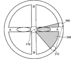
Fig. 4 A, Fig. 4 B and Fig. 4 C are respectively front view, side view and the rear view of choke device 300 when inverted draft takes place in the present embodiment.When in the array fan (as 120) during a fan fails, the inverted draft that produces can flow into choke device 300 of the present invention with the direction that penetrates Fig. 3 A (front view) paper, and flow out this choke device 300 with the direction that passes Fig. 3 C (rear view) paper.The same time, this inverted draft also pours into this inverted draft air intake branch 314 by this inverted draft inlet hole 322, pour at last in the ring pipe 312, and the zone on this first movable balls 340 and 350 grip hold arcs of second movable balls (340-A-350) forms malleation; In addition, this inverted draft also can be through this air-flow inlet hole 324 forward, to the zone on 340 grip hold arcs of two first movable balls (340-B-340) about in the ring pipe 312 and about zone on 350 grip hold arcs of two second movable balls (350-B-350) form negative pressure.Under malleation and action of negative pressure, first movable balls 340 of the present invention is the axle center with second end (place of entity 370) of this film 360 promptly, slides toward the direction away from this film 360 the 3rd end (i.e. second movable balls 350) along this ring pipe 312; Same, second movable balls 350 of the present invention is the axle center with second end (place of entity 370) of this film 360 also, and slides toward the direction away from these film 360 first ends (i.e. first movable balls 340) along this ring pipe 312.Afterwards; Each film 360 of the present invention can expand into one fan-shaped because of first movable balls 340 and both relative movement of second movable balls 350; And, finally reach and hinder the purpose that inverted draft flows toward the direction that flows into fan along with inverted draft strengthens and expands into shown in Fig. 5 A, Fig. 5 B and Fig. 5 C (Fig. 5 A, Fig. 5 B and Fig. 5 C are respectively front view, side view and the rear view of choke device 300 when inverted draft is the strongest in the present embodiment) semicirclely gradually.It should be noted that like preamble saidly, film 360 is not defined as given shape; Though in this most preferred embodiment; Film 360 is for fan-shaped and be expanded to fully at last and cover whole fan, but in other embodiments, as long as film 360 can appropriateness open; Even if fail to cover fully fan, also can reach the effect that hinders inverted draft.
The present invention not only can hinder it and flow when inverted draft takes place, also can be when fan runs well conducting air-flow forward.Fig. 6 A, Fig. 6 B and Fig. 6 C are respectively front view, side view and the rear view of choke device 300 when inverted draft changes over air-flow forward in the present embodiment.When inverted draft changes over forward air-flow, produce forward that air-flow flows into choke device 300 of the present invention with the direction that penetrates Fig. 3 C (rear view) paper again, and flow out this choke device 300 with the direction that passes Fig. 3 A (front view) paper.The same time; This forward air-flow also by this forward air-flow inlet hole 324 pour into this forward air-flow air intake branch 316; Pour at last in the ring pipe 312, and to the zone on 340 grip hold arcs of two first movable balls (340-B-340) about in the ring pipe 312 and about zone on 350 grip hold arcs of two second movable balls (350-B-350) form malleation; In addition, this forward air-flow also can pass through this inverted draft inlet hole 324, this first movable balls in the ring pipe 312 340 and zone on 350 grip hold arcs of this second movable balls (340-A-350) are formed negative pressure.Under malleation and action of negative pressure, first movable balls 340 of the present invention is the axle center with second end (place of entity 370) of this film 360 promptly, and slides along this ring pipe 312 toward the direction near this film 360 the 3rd end (i.e. second movable balls 350); Same, second movable balls 350 of the present invention is the axle center with second end (place of entity 370) of this film 360 also, and slides toward the direction near these film 360 first ends (i.e. first movable balls 340) along this ring pipe 312.Afterwards; Each film 360 of the present invention can be folded into fan-shaped because of both relative movement of this first movable balls 340 and this second movable balls 350 by semicircle; And shown in Fig. 7 A, Fig. 7 B and Fig. 7 C (Fig. 7 A, Fig. 7 B and Fig. 7 C are respectively front view, side view and the rear view of choke device 300 when forward air-flow is the strongest in the present embodiment); Along with air-flow forward strengthens and will fold gradually in the both sides of this inverted draft air intake branch 314, finally reach the forward purpose of air-flow of conducting.
Can know from preamble; According to spirit of the present invention; As long as can form different air pressure in the both sides of first movable balls 340 or second movable balls 350; Film 360 then of the present invention can be expanded or folds because of the relative movement of this first movable balls 340 and second movable balls 350, reaches to intercept or the purpose of conducting air-flow.Therefore; Though in most preferred embodiment of the present invention; In order to reach higher efficient, perforates are in inverted draft air intake branch 314 and forward on the air-flow air intake branch 316 respectively for its inverted draft inlet hole 322 and air-flow inlet hole 324 forward, but other embodiments needn't be as limit.For example, in certain embodiments, body 310 can only have ring pipe 312 and not have inverted draft air intake branch 314 and air-flow air intake branch 316 forward.At this moment; Inverted draft inlet hole 322 and forward but 324 perforates of air-flow inlet hole are any on ring pipe 310 can make inverted draft inlet hole 322 and air-flow inlet hole 324 position of movable balls (340 or 350) (purpose is utilizing this movable balls to intercept two inlet holes 322 and 324 s' air-flow) at interval forward is for example respectively at A place and the B place of Fig. 3 A.As long as it should be noted that to meet aforementioned principle, inverted draft inlet hole 322 of the present invention is with forward number, shape, the size of air-flow inlet hole 324 also needn't be exceeded with previous embodiment.
In a better embodiment, can in ring pipe, move in the appropriate region in order to make first movable balls 340 of the present invention and second movable balls 350, choke device 300 of the present invention also comprises the first movable balls limiter 380 and the second movable balls limiter 390.If inverted draft inlet hole 322 perforates among the embodiment are on inverted draft suction tude 314 time; The first movable balls limiter 380 of the present invention can be in order to limit this first movable balls 340; It is active in does not stop that this inverted draft air intake branch 314 is communicated with the place with this ring pipe 312; Position A shown in Fig. 3 A hinders inverted draft to be got in the ring pipe 312 by inverted draft air intake branch 314 to avoid first movable balls 340; If in one embodiment, its inverted draft inlet hole 322 perforates were in 312 last times of ring pipe, and the first movable balls limiter 380 then of the present invention can make it be active in the position that does not stop this inverted draft inlet hole in order to limit this first movable balls 340.In like manner; If forward air-flow inlet hole 324 perforates among the embodiment are on air-flow suction tude 316 forward the time; The second movable balls limiter 390 of the present invention can be in order to limit this second movable balls 350; Make its be active in do not stop this forward air-flow air intake branch 316 be communicated with the place with this ring pipe 312, the position B shown in Fig. 3 A hinders forward air-flow to be got in the ring pipes 312 by air-flow air intake branch 316 forward to avoid first movable balls 350; If in one embodiment, forward 324 perforates of air-flow inlet hole were in 312 last times of ring pipe for they, and the second movable balls limiter 390 then of the present invention can be active in it in order to limit this second movable balls 350 not stop this forward position of air-flow inlet hole.In this most preferred embodiment, the first movable balls limiter 380 and the second movable balls limiter 390 are the tube wall that shrinks in the ring pipe 312, or the projection in the tube wall, have the motion with the restraint ball of the internal diameter that is slightly less than the movable balls sphere diameter.And; The first movable balls limiter 380 and the second movable balls limiter 390 can be arranged at the position of opening on the ring pipe at a distance from 90 degree respectively; So that first movable balls 340 and second movable balls 350 have maximum range of movement, and then make film 360 be able to be expanded to maximum and fold to minimum.
Although in the aforementioned embodiment; Three end points of film 360 are respectively an end, and to fix (second end that is positioned at entity 370 places) and two ends (be connected in first end of first movable balls 340 and be connected in the 3rd end of second movable balls 350) movable; Film 360 has that an end is movable to get final product at least, at this moment but in other embodiments; Other two ends can be fixed, or all are connected to movable balls and activity.Fig. 8 A is the front view of the choke device of another embodiment of the present invention.In this embodiment; When film 360 only movable and other two ends of an end (first end) for fixedly the time; Its second end can be arranged in any position (the for example positions at entity 370 places of figure) of the border circular areas that ring pipe 312 centered on; With as the axle center of this first end along ring pipe rotation, the 3rd end then can be fixed in any position in the space, for example is fixed in (entity 372 positions) in the ring pipe 312.Fig. 8 B is the front view of the choke device of another embodiment of the present invention.In the embodiment of Fig. 8 B; When film 360 3 ends are all movable; First end and the 3rd end such as aforementioned first movable balls 340 and second movable balls 350 of being connected to; Second end then can be another movable balls 355 that is arranged in ring pipe 312, but by the range of movement less zone (promptly relatively motionless) of other limiters (figure do not show) restraint in movable balls 340 relatively and 350, with as this first end and the 3rd end axle center along the ring pipe rotation.
Preamble has detailed choke device 300 of the present invention.Except this choke device 300, the present invention provides a blower module in addition.Please with reference to Fig. 3 B, blower module of the present invention has been integrated the choke device 300 in array fan as shown in Figure 1 120 and the previous embodiment.Array fan of the present invention comprises at least two fans, in order to produce one forward air-flow and produce an inverted draft when fan (for example fan 122) lost efficacy in this array fan with for a thermal source (like the thermal source 110 of Fig. 1) heat radiation.In previous embodiment; Choke device in the blower module of the present invention (choke device 300 with Fig. 3 A is an example) is arranged at the inlet side or the air side of a fan in this array fan 120; Comprise: a body 310, one first movable balls 340, and a film 360.Wherein this body 310 comprises a ring pipe 312 at least, also comprises an inverted draft air intake branch 314 and/or air-flow air intake branch 316 forward in certain embodiments.Comprise at least one inverted draft inlet hole 322 on the body 310, a side of inverted draft is met in perforate above body 310; And at least one forward air-flow inlet hole 324, a forward side of air-flow is met in perforate above body 310.This first movable balls 340 is positioned at this ring pipe 312; And this film 360 has one first end, one second end and one the 3rd end, and is connected to this first movable balls 340 with this first end.Wherein, The 3rd end can be positioned at a fixed position (shown in Fig. 8 A); Perhaps be connected to one second movable balls 350 that is arranged in ring pipe 312, and this second end can be positioned at another fixed position, perhaps is connected to another movable balls (shown in Fig. 8 B) that is arranged in ring pipe 312.Aforesaid inverted draft inlet hole 314 is axle center and sliding along this ring pipe 312 toward the directions away from the 3rd end in order to let this inverted draft pour in this ring pipe 312 to order about this first movable balls 340 with this second end, and then expands this film 360 to hinder this inverted draft; And aforesaid forward air-flow inlet hole 324 is axle center and sliding along this ring pipe 312 toward the directions near the 3rd end in order to let air-flow forward pour in this ring pipe 312 to order about this first movable balls 340 with this second end, and then folds this film 360 with this air-flow forward of conducting.Because preamble details the transformable variform of choke device of the present invention through Fig. 3 A~8B; Those of ordinary skills can understand the various possible enforcement appearance attitude of blower module of the present invention with reference to preamble; Therefore, this paper no longer gives unnecessary details other embodiments of blower module.
Though the present invention with preferred embodiment openly as above; So it is not in order to limit scope of the present invention; Any those of ordinary skills; Do not breaking away from the spirit and scope of the present invention, when can doing a little change and retouching, so protection scope of the present invention is as the criterion when looking the scope that claim defined of enclosing.
Claims (11)
1. a choke device is arranged among the array fan; Wherein this array fan comprises at least two fans, in order to producing an air-flow forward, and in this array fan, produces an inverted draft during fan fails; This choke device comprises:
One body comprises a ring pipe; And at least one inverted draft inlet hole;
One first movable balls is positioned at this ring pipe; And
One film has one first end, one second end and one the 3rd end, and wherein this first end is connected to this first movable balls;
Wherein, Said at least one inverted draft inlet hole is axle center and sliding along this ring pipe toward the direction away from the 3rd end in order to let this inverted draft pour in this ring pipe to order about this first movable balls with this second end, and then expands this film to hinder this inverted draft.
2. choke device as claimed in claim 1; Wherein this body also comprises at least one forward air-flow inlet hole; Is axle center and sliding along this ring pipe toward the direction near the 3rd end in order to let air-flow forward pour in this ring pipe to order about this first movable balls with this second end, and then folds this film with this air-flow forward of conducting.
3. choke device as claimed in claim 1, wherein this body also comprises at least one inverted draft air intake branch, it is communicated with this ring pipe with at least one end.
4. choke device as claimed in claim 3, setting of wherein said at least one inverted draft inlet hole and perforate are met a side of inverted draft in the face of this ring pipe or this inverted draft air intake branch.
5. choke device as claimed in claim 2, wherein this body also comprises at least one forward air-flow air intake branch, it is communicated with this ring pipe with at least one end.
6. choke device as claimed in claim 5, setting of wherein said at least one inlet hole with the wind and perforate in this ring pipe or this forward the face of air-flow air intake branch meet a forward side of air-flow.
7. choke device as claimed in claim 1, wherein this second end of this film is connected to a fixed position.
8. choke device as claimed in claim 7, wherein this fixed position is positioned within this ring pipe institute region surrounded.
9. choke device as claimed in claim 2; Also comprise one second movable balls; Be positioned at this ring pipe; Wherein the 3rd end of this film is connected to this second movable balls, and this second movable balls is when this inverted draft pours into this ring pipe, is axle center and sliding along this ring pipe toward the direction away from this first end with this second end; And at this when forward air-flow pours into this ring pipe, be axle center and sliding toward direction near this first end along this ring pipe with this second end.
10. choke device as claimed in claim 9 also comprises one first movable balls limiter, is active in the position that does not stop this this ring pipe of inverted draft entering in order to limit this first movable balls activity and this second movable balls.
11. choke device as claimed in claim 9 also comprises one second movable balls limiter, in order to limit this first movable balls and this second movable balls be active in do not stop this forward air-flow get into the position of this ring pipe.
Priority Applications (1)
| Application Number | Priority Date | Filing Date | Title |
|---|---|---|---|
| CN201110114910.9A CN102758801B (en) | 2011-04-29 | 2011-04-29 | Wind stop device |
Applications Claiming Priority (1)
| Application Number | Priority Date | Filing Date | Title |
|---|---|---|---|
| CN201110114910.9A CN102758801B (en) | 2011-04-29 | 2011-04-29 | Wind stop device |
Publications (2)
| Publication Number | Publication Date |
|---|---|
| CN102758801A true CN102758801A (en) | 2012-10-31 |
| CN102758801B CN102758801B (en) | 2014-10-01 |
Family
ID=47053392
Family Applications (1)
| Application Number | Title | Priority Date | Filing Date |
|---|---|---|---|
| CN201110114910.9A Active CN102758801B (en) | 2011-04-29 | 2011-04-29 | Wind stop device |
Country Status (1)
| Country | Link |
|---|---|
| CN (1) | CN102758801B (en) |
Citations (9)
| Publication number | Priority date | Publication date | Assignee | Title |
|---|---|---|---|---|
| US6005700A (en) * | 1996-06-26 | 1999-12-21 | Aironet Wireless Communications, Inc. | Computer peripheral device with detachable portion and light display |
| US6042348A (en) * | 1998-05-11 | 2000-03-28 | Lucent Technologies Inc. | Protective shutter assembly for a forced air cooling system |
| US6181557B1 (en) * | 1999-10-29 | 2001-01-30 | Motorola, Inc. | Electronic component, method of cooling, and damper therefor |
| CN2526565Y (en) * | 2001-12-20 | 2002-12-18 | 英业达股份有限公司 | Turbulence preventing device for server fan |
| CN1466413A (en) * | 2002-06-10 | 2004-01-07 | 台达电子工业股份有限公司 | Flow direction control mechanism |
| JP2004112899A (en) * | 2002-09-18 | 2004-04-08 | Yaskawa Electric Corp | Backup fan switching structure |
| TW200612811A (en) * | 2004-10-15 | 2006-04-16 | Delta Electronics Inc | Heat dissipation module and flow direction control structure thereof |
| CN201167447Y (en) * | 2008-02-27 | 2008-12-17 | 杭州华三通信技术有限公司 | Radiating device for electronic appliances |
| TWM355304U (en) * | 2008-12-10 | 2009-04-21 | Hipro Electronics Taiwan Co Ltd | Air flow checking structure and centrifugal fan device having the same |
-
2011
- 2011-04-29 CN CN201110114910.9A patent/CN102758801B/en active Active
Patent Citations (9)
| Publication number | Priority date | Publication date | Assignee | Title |
|---|---|---|---|---|
| US6005700A (en) * | 1996-06-26 | 1999-12-21 | Aironet Wireless Communications, Inc. | Computer peripheral device with detachable portion and light display |
| US6042348A (en) * | 1998-05-11 | 2000-03-28 | Lucent Technologies Inc. | Protective shutter assembly for a forced air cooling system |
| US6181557B1 (en) * | 1999-10-29 | 2001-01-30 | Motorola, Inc. | Electronic component, method of cooling, and damper therefor |
| CN2526565Y (en) * | 2001-12-20 | 2002-12-18 | 英业达股份有限公司 | Turbulence preventing device for server fan |
| CN1466413A (en) * | 2002-06-10 | 2004-01-07 | 台达电子工业股份有限公司 | Flow direction control mechanism |
| JP2004112899A (en) * | 2002-09-18 | 2004-04-08 | Yaskawa Electric Corp | Backup fan switching structure |
| TW200612811A (en) * | 2004-10-15 | 2006-04-16 | Delta Electronics Inc | Heat dissipation module and flow direction control structure thereof |
| CN201167447Y (en) * | 2008-02-27 | 2008-12-17 | 杭州华三通信技术有限公司 | Radiating device for electronic appliances |
| TWM355304U (en) * | 2008-12-10 | 2009-04-21 | Hipro Electronics Taiwan Co Ltd | Air flow checking structure and centrifugal fan device having the same |
Also Published As
| Publication number | Publication date |
|---|---|
| CN102758801B (en) | 2014-10-01 |
Similar Documents
| Publication | Publication Date | Title |
|---|---|---|
| CN209014815U (en) | The head-mounted display worn by user | |
| US20160192601A1 (en) | Plant cultivation device | |
| CN104515284B (en) | Air-conditioner with rotation air exhausting structure | |
| CN102203430A (en) | Blower and heat pump utilizing said blower | |
| JP6749353B2 (en) | Blower | |
| BR112020007846B1 (en) | AIR CONDITIONING AND METHOD FOR AIR CONDITIONING CONTROL | |
| CN104390268A (en) | Ceiling air conditioner and air supplying method using same | |
| WO2017145275A1 (en) | Blower and air conditioner employing same | |
| CN104344265B (en) | A kind of passive fan structure light fixture | |
| CN104374065A (en) | Air duct system, air supply method thereof, fan with air duct system and air conditioner with air duct system | |
| CN206141808U (en) | Horn subassembly and aircraft of aircraft | |
| CN204806547U (en) | Suspension type fan | |
| CN102758801A (en) | Wind stop device | |
| CN207132460U (en) | For air conditioner scattered wind part and there is its air conditioner | |
| EP3684151B1 (en) | Heat dissipation structure, cabinet, and communication system | |
| CN104990144A (en) | Ceiling fan | |
| CN204227556U (en) | Air-conditioner | |
| CN105333588A (en) | Air conditioner indoor unit | |
| KR101483340B1 (en) | Fan | |
| US20210131445A1 (en) | Bladeless fan | |
| ITUB20159229A1 (en) | FLIGHT ROOM FOR WIND GALLERY AND ASSOCIATED WIND GALLERY. | |
| CN202656823U (en) | Blow-off device for vehicle | |
| CN107490061A (en) | For air conditioner scattered wind part and there is its air conditioner | |
| CN106839096A (en) | Ceiling air conditioner | |
| RU2015131100A (en) | AIR SPACE AIRCRAFT |
Legal Events
| Date | Code | Title | Description |
|---|---|---|---|
| C06 | Publication | ||
| PB01 | Publication | ||
| C10 | Entry into substantive examination | ||
| SE01 | Entry into force of request for substantive examination | ||
| C14 | Grant of patent or utility model | ||
| GR01 | Patent grant |