The application be the name submitted on April 28th, 2009 be called DEVICES AND METHODS FOR THE TREATMENT OF HEART FAILURE have a serial number 12/447; The part continuation application of 617 the non-temporary patent application of the U.S. common co-pending, it integrally is attached among this paper by reference.Has serial number 12/447; The non-temporary patent application of 617 the U.S. is submitted to according to 35 U.S.C. § 371; Therefore the name that requires on November 7th, 2007 to submit to is called the priority of International Application PCT/AU2007/001704 of DEVICES AND METHODS FOR TREATMENT OF HEART FAILURE, and it integrally is attached among this paper by reference.PCT/AU2007/001704 requires the priority of the australian patent application AU 2006906202 of submission on November 7th, 2006, and it is attached among this paper by reference.The name that the application also requires on JIUYUE 4th, 2009 to submit to is called the rights and interests of the U.S. Provisional Patent Application with serial number 61/240,085 of DEVICES AND METHODS TO TREAT HEART FAILURE, and it integrally is attached among this paper by reference.
Summary of the invention
Therefore, the reduction that the objective of the invention is to realize pulmonary venous pressure is to alleviate the symptom of diastolic heart failure.Another object of the present invention is between left atrium and right atrium, to produce controlled outlet to flow to right atrium with the blood that allows q.s from left atrium, minimizes but make from the blood flow of right atrium to left atrium.
Another object of the present invention is to produce the controlled outlet that will react the pressure differential between the left atrium.Another object of the present invention provides room pressure discharge (elimination) device that anti-tampon gets into left atrium.
The present invention solves these and other needs through discharger is provided; It is included in the controlled openings between left atrium and the right atrium in certain embodiments or prolongs tubular opening; It allows a certain amount of blood to be discharged to the right heart from the left heart, thereby reduces PLA left atrial pressure and reduce the symptom that is associated with diastolic heart failure.
The intracardiac method that extrudes mouth, places conduit, laying method and treatment heart failure of a plurality of uniquenesses has been proposed.The intracardiac extrusion that proposes mouthful allows PLA left atrial pressure and the resultant patient symptom of enough flows to alleviate raising from left atrium to right atrium, but and restriction from the flow of right atrium to left atrium so that thrombosis or other embolism materials get into the potential energy minimization of arterial circulation.
In addition, the intracardiac extrusion mouth that is proposed has solved the flow of the direction in control edge under the situation that pressure very little on the device changes but has made along the minimized problem of the flow of other direction.
And the intracardiac mouth that extrudes of proposition has solved minimizing calcium deposition, the proteins deposited and thrombotic problem in the lower pressure environment.
In addition, the intracardiac mouth that extrudes that is proposed has solved the problem that remainder to the damage of interatrial septum and left atrium abuts against wall superpressure (this possibly cause the function that the injury of tissue and possible patient's untoward reaction or room are extruded mouthful impaired).
In addition, in having the patient body of heart failure, usually see atrial arrhythmia, and it possibly partly be that PLA left atrial pressure by chronic raising causes.Therefore, the PLA left atrial pressure of raising alleviates the minimizing that can cause atrial fibrillation.
The invention provides the room extrudes mouthful, places conduit, is used for device is placed on the method for the interatrial septum in patient's the heart and is used to make the method for the symptom of heart failure, particularly diastolic heart failure.
In an embodiment, extrusion mouth in room comprises body assembly and flow control element; Body assembly comprises the flexibility that is suitable in the patient body, using, the mesh of opening basically (mesh).Flow control element is attached at least one point and the flow control element of body assembly, and it provides bigger flow resistance along other direction along a direction ratio.
In an embodiment, extrusion mouth in room comprises body assembly and flow control element; Body assembly comprises the flexibility that is suitable in the patient body, using, the mesh of opening basically.Flow control element is attached at least one point of body assembly and opens at least in part when not having pressure differential to flow at (promptly from a side of flow control element to opposite side) on the flow control element.
In an embodiment, extrusion mouth in room comprises body assembly and flow control element; Body assembly comprises core section and at least one flange section; The end of flange Duan Yuxin section is in aggregates or be attached at least one point that is adjacent to core section end; The central longitudinal axis of flange Duan Congxin section radially stretches out.Flow control element is attached at least one point and flow control element provides bigger flow resistance in opposite direction along a direction ratio along the core section.
In an embodiment, extrusion mouth in room comprises body assembly and flow control element; Body assembly comprises columniform basically core section and at least one flange section; The end of flange Duan Yuxin section is in aggregates or be attached to a point that is adjacent to core section end at least; The central longitudinal axis of flange Duan Congxin section radially stretches out.Flow control element is attached at least one point and flow control element provides bigger flow resistance along a direction ratio along other direction along the core section.
In an embodiment, extrusion mouth in room comprises body assembly and flow control element.Body assembly comprises columniform basically core section and is in aggregates or be attached at least one flange section of its at least one end with the core section; The radial axis ground of flange Duan Congxin section stretches out.Flow control element is attached to along the core section and opens at least in part when there are not pressure differential at least one point and flow control element on flow control element to flow.
In an embodiment, extrusion mouth in room comprises body assembly and flow control element.Body assembly comprises columniform basically core section and at least one flange section, and this flange Duan Yuxin section is in aggregates or be attached to its at least one end and extend away from the axis of core section.Flow control element is attached at least one point and along other direction bigger flow resistance is provided along a direction ratio along flange assembly.
In an embodiment, extrusion mouth in room comprises body assembly and flow control element.Body assembly comprises columniform basically core section and at least one flange section, and this flange Duan Yuxin section is in aggregates or be attached to its at least one end and extend away from the axis of core section.Flow control element is opened when flange assembly is attached at least one point and on flow control element, do not have pressure differential to flow at least in part.
In an embodiment, extrusion mouth in room comprises body assembly and flow control element.Body assembly comprises columniform basically core section and at least one flange section, and this flange Duan Yuxin section is in aggregates or be attached to its at least one end and extend away from the axis of core section.Flow control element extends on the flange assembly at least in part and produces the salable contact of interatrial septum and along other direction bigger flow resistance is provided along a direction ratio.
In an embodiment, extrusion mouth in room comprises body assembly and flow control element.Body assembly comprises columniform basically core section and at least one flange section, and this flange Duan Yuxin section is in aggregates or be attached to its at least one end and extend away from the axis of core section.Flow control element is attached to flange assembly and opens at least in part when producing the salable connection of interatrial septum and on flow control element, not having pressure differential to flow.
In an embodiment, the room pressure export comprises body assembly and the flow control element with first end and the second end; Body assembly comprises the core section, and this core section comprises in aggregates or be attached at least one flange section of this at least one point and in aggregates or be attached at least one flange section of this at least one point with at least one point that is adjacent to core section the second end with at least one point that is adjacent to core section first end; The central longitudinal axis of flange Duan Congxin section radially stretches out and the flange section be oriented make its when being disposed not against each other.Flow control element is attached at least one point and flow control element provides bigger flow resistance along a direction ratio along other direction along the core section.
In an embodiment, the room pressure export comprises body assembly and the flow control element with first end and the second end; Body assembly comprises the core section, and this core section comprises in aggregates or be attached at least one flange section of this at least one point and in aggregates or be attached at least one flange section of this at least one point with at least one point that is adjacent to core section the second end with at least one point that is adjacent to core section first end; The central longitudinal axis of flange Duan Congxin section radially stretches out and the flange section be oriented make its when being disposed not against each other.Flow control element is attached to along the core section and opens at least in part when there are not pressure differential at least one point and flow control element on flow control element to flow.
In an embodiment, extrusion mouth in room comprises body assembly with first end and the second end and the flow control element that is made up of at least one lobule; Body assembly comprises columniform basically core section and many flange sections, and at least one point of every side of this flange section and main paragraph is in aggregates or be attached to this at least one point and radially stretch out from the central longitudinal axis of core section; Number in the flange section of the either side of core section is the integral multiple of lobule number.
In an embodiment, extrusion mouth in room comprises body assembly with first end and the second end and the flow control element that is made up of at least one lobule; Body assembly comprises columniform basically core section and many flange sections, and at least one point of every side of this flange section and main paragraph is in aggregates or be attached to this at least one point and radially stretch out from the central longitudinal axis of core section; The number of flange section is the integral multiple of lobule number.Flow control element is attached at least one point and the flow control element of body assembly, and it provides bigger flow resistance along other direction along a direction ratio.
In an embodiment, extrusion mouth in room comprises body assembly with first end and the second end and the flow control element that is made up of at least one lobule; Body assembly comprises columniform basically core section and many flange sections, and at least one point of every side of this flange section and main paragraph is in aggregates or be attached to this at least one point and radially stretch out from the central longitudinal axis of core section; The number of flange section is certain multiple of lobule number.When being attached at least one point of body assembly and on flow control element, not having pressure differential, opens at least in part flow control element to flow.
In an embodiment, implant system comprises that the room extrudes mouth and the placement conduit that is used to treat heart failure.Implant system is made up of body assembly and flow control element.Body assembly is made up of columniform core section basically and at least one flange section, and this flange Duan Yuxin section is in aggregates or be attached to its at least one end and radially extend away from the core section.Flow control element is attached at least one point and along other direction bigger flow resistance is provided along a direction ratio along the core section.Placing conduit is made up of interior axle and outer shaft.Interior axle comprises elongated tubular and grip member.Interior axle also comprises at least one chamber of extending along at least a portion of the length of interior axle.Outer shaft comprises elongated hollow tube or sheath and the different grip members that dock slidably with first in command's parts.
In an embodiment, implant system comprises that the room extrudes mouth and the placement conduit that is used to treat heart failure.Implant system is made up of body assembly and flow control element.Body assembly is made up of columniform core section basically and at least one flange section, and this flange section and body assembly are in aggregates or be attached to its at least one end and radially extend away from main paragraph.Flow control element is attached at least one point and along other direction bigger flow resistance is provided along a direction ratio along flange.Placing conduit is made up of interior axle and outer shaft.Interior axle comprises elongated tubular and grip member.Interior axle also comprises at least one chamber of extending along at least a portion of the length of interior axle.Outer shaft comprises elongated hollow tube (or sheath) and the different grip members that dock slidably with first in command's parts.
In an embodiment, implant system comprises that the room extrudes mouth and the placement conduit that is used to treat heart failure.Implant system is made up of body assembly and flow control element.Body assembly is made up of columniform core section basically and at least one flange section, and this flange section and body assembly are in aggregates or be attached to its at least one end and radially extend away from main paragraph.Flow control element is attached at least one point and along other direction bigger flow resistance is provided along a direction ratio along flange.Placing conduit is made up of interior axle and outer shaft.Interior axle comprises the elongated tubular and the grip member of the circumferential groove that has at least one flange or in external diameter, form.Interior axle also comprises at least one chamber of extending along at least a portion of the length of interior axle.Outer shaft comprises elongated hollow tube (or sheath) and the different grip members that dock slidably with first in command's parts.
In other embodiments; The present invention includes the device that is used to treat the intravital heart disease of patient; This device comprises body element, and this body element has the core section that limits passage, comprises first annular flange of a plurality of flange sections and second annular flange that comprises a plurality of flange sections.In an embodiment, at least a portion of one in the flange section is more soft or more not soft than other part of the remainder of flange section or body element, includes but not limited to the cylindrical core section.
In other embodiments, this device comprises the 3rd or the intermediate annular flange that is used for adhering to better septum wall.
In other embodiments, this device comprises the flow control element that is constructed to make blood flow aiming desired orientation.
In other embodiments, the present invention is configured to during disposing, more easily fetched.This type of embodiment can be included at least one the extension flange section among in the annular flange among other element, it can be maintained at when other part of deployment devices places in the conduit.
In an embodiment; The room is extruded the method that mouth is placed into the appropriate location can comprise series of steps: the blood vessel access that leads to heart is positioned and approaching; Through passage thus the conductor conduit is placed among in the atrium of heart; The interatrial septum is positioned between the left atrium, in the interatrial septum, produces opening, make to comprise placement conduit that the room extrudes mouthful and advance among in the atrium and the opening through producing in the interatrial septum between left atrium then; And controllably dispose the room then and extrude mouth, therefore it can be fixedly connected to the interatrial septum.
The deployment that the room extrudes mouth preferably takes place in series of steps; Comprise the placement conduit is advanced through the barrier film opening; Next disposes first flange; The 3rd makes and places the conduit withdrawal against septum wall first flange being positioned, and the 4th affixes one's name to second flange at a sidepiece of the septum wall relative with first flange.
Among the embodiment in disclosed device implantation interatrial septum with this paper, can be through postcava via placing the conductor conduit to the femoral vein of right atrium.
Can use other approach, comprise via jugular vein and pass through superior vena cava; Through aorta, the process aortic valve also gets into left atrium via femoral artery; Through aorta, the process aortic valve also gets into left atrium via brachial artery; Pass through superior vena cava via basilic vein; Pass through superior vena cava via cephalic vein; In art, through for this reason or the opening that during the program of carrying out from other purpose, in right atrium, produces; In art through for this reason or the opening that in left atrium, produces in the program of carrying out from other purpose; Or via placing the conductor conduit through interatrial septum location and the lead that is arranged in pulmonary artery.
About placing conduit, in certain embodiments, will place catheter design for serving as the conductor conduit and placing conduit, eliminated needs to the conduit exchange.And in other embodiments, with the conductor conduit, place conduit or both and only be configured on the part of its length by exchange to avoid handling the needs of lead of two double-lengths that are conduit at least.In other embodiments, the conductor conduit place conduit or both to have a preform crooked so that can realize and the orthogonal basically placement conduit orientation of septum wall.Conduit can be crooked between 30o and 45o away from the conduit axis away from the some place between the far-end 5 of placing conduit and 15 centimetres.
To be placed in the embodiments of the invention in the interatrial septum at device of the present invention, and can use the conductor conduit to carry out the opening in the barrier film extruding in mouthful program that the layout program is separated with the room.Can keep approaching through opening via the line guiding piece that is arranged in right atrium or pulmonary artery.Can be via using the placement conduit to form this opening as the distal ports of a part of placing conduit.
Can be used as the part of said program or use air bag or other expansion gear that opening is expanded in advance as single program.
On the other hand, as single, extrude mouthful part of the program that the placement program is unified with the room and form opening and make its expansion.This can be through integrated air bag or other swelling part as a part of placing conduit and opening is expanded realize as placing the part that the room extrudes mouthful.For example, this can use air bag to realize, this air bag can be folded realizing that little loading distributes, and will have suitable pressure capability and suitable durability so that the barrier film opening extrudes mouth expansion together with the room.
Can be formed on the opening that forms in the interatrial septum through barrier film in the position of septum primum through promoting catheter tip.Because this barrier film is normally extremely thin, so can pass through not having directly to promote far-end under the situation of sizable power.
In the replacement method, can form the opening in the interatrial septum with the cutting tool that advances through conductor conduit or placement conduit.This instrument preferably includes blade and axle.This blade comprises at least two surfaces and an edge.This edge sharp and form with certain angle makes blade along with before it and then incision and pass through barrier film.
In another embodiment, can form the opening in the interatrial septum with the cutting tool that advances through conductor conduit or placement conduit.This instrument preferably includes blade and axle.Blade comprises at least two surfaces and angled two sharp independent edges, makes blade along with before it and then incision and through barrier film, and substantially with x shape opening cutting barrier film.
In another embodiment, can form the opening in the interatrial septum with the punching tool that advances through conductor conduit or placement conduit.This punching tool preferably includes cutting assembly and axle.Cutting assembly preferably includes the hollow cone shape that has sharp edges along the base circumference.Cutting assembly is connected to a point on the axle at least, and is oriented substantially and makes conical tip point to abaxial direction.
In a method, can operate cutting assembly through making the circular cone assembly advance through the interatrial septum and subsequently it retracted to form circular substantially opening.
In another method, can be through making the circular cone assembly advance and it being rotated operate cutting assembly along with it is pulled subsequently, to produce circular cutting action against the interatrial septum through the interatrial septum.
In another embodiment, cutting tool can be formed by at least one cutting element and an axle.Cutting element is connected to a point along axle at least, and the other end of cutting element by adjustably the location, make it can be positioned at the next to axis limit or with certain angle away from axle.In order to place cutting tool, cutting element is placed on the next to axis limit and it is advanced through barrier film.Then, can cutting element be adjusted to the second position, it is compared with primary importance radially more away from axle, and can axle be orientated as and make cutting element apply lateral stress to barrier film.Can cutting element be designed to by this way barrier film cut.In another method,, axle and cutting element can make the cutting tool rotation in case being reorientated, and make cutting movement to cut out and pass membranous circular substantially hole.
In an embodiment, cutting element is the circle line.
In another embodiment, can cutting element be connected to an outfan of power supply, it can provide appropriate signals to cutting element, and its another outfan is connected to the earth plate of the placed that abuts against patient.Can between cutting element and earth plate, place appropriate potential near lead, to cause concentrated electric current density, wear diaphragm tissue to help to cut.
In another embodiment, cutting element be one section by the pipe of rip cutting and suitably formed to produce the cut edge.Between resting period, cutting element is controllably orientated as along with axle advances through placing conduit and abutting against axle through the opening that in the interatrial septum, produces.In case be positioned, then place conduit withdrawal and axle and be located in the barrier film.In case by location by this way, then can cutting element controllably be adjusted to the second position, it is compared with primary importance radially more away from axle, and axle orientated as make cutting element apply lateral stress barrier film.
In another method; According to the present invention; In the interatrial septum, produce the little interatrial septum of diameter of pressing the outer surface of the main body of handling than the room, make to extrude when mouthful being deployed at first the interatrial septum in, have certain compression of the main body of extrusion mouth from barrier film against the room when the room.
With reference now to being used for that the room is extruded mouth, position the placement conduit with controlled placement; On the one hand, placing conduit is made up of inner member and external member.
In an embodiment; External member is made up of pipe component and first in command's parts; Outer shaft less than about 16F, and is formed by smooth and resilient material suitably on diameter, so that the room that restriction is loaded extrudes mouthful; And allow to load smoothly and dispose, such as PTFE, FEP, Tefzel, PVDF, HDPE or other suitable material.
In an embodiment, inner member is made up of with the second in command's parts that are attached to near-end at least one pipe component of the inner chamber with at least a portion through pipe component, and second in command's parts are attached to first in command's parts slidably.
In an embodiment, via the screw rod that tilts the grip member interconnection is made it possible to realize inner member advancing with respect to external member through rotation outer shaft handle in the axle handle in keeping.
In an embodiment, grip member comprises and prevents that grip member is moved beyond the locking mechanism of certain predetermined length each other.
In an embodiment, grip member comprises at least two locking mechanisms, and it prevents that grip member is moved beyond two different predetermined lengths each other.
In an embodiment, inner member comprises the reinforcing element that is adjacent to remote area.
In an embodiment, the system that is used to treat patient's heart failure is extruded mouthful by the room and apparatus for placing is formed.The room extrudes mouth and comprises body section and flow control element.Body section comprises core section and at least one flange section.The flange section comprises the centre portion that is adjacent to main body and has the end section of the wall thickness bigger than centre portion.Axle and outer shaft in apparatus for placing comprises.In axle comprise external diameter and the inner chamber from far-end towards proximal extension at least in part.Outer shaft comprises external diameter and internal diameter.In axle have along the constriction or the circumferential groove of at least a portion of its length, it has than the little diameter of at least a portion at the inner member of constriction far-end; The space that forms between the inside of the outside of constriction and outer shaft be enough to comprise folding or compression room of the present invention extrudes mouthful and inside at the outside of non-constriction and outer shaft between the insufficient space that forms extrude mouth to comprise the room.
In an embodiment, the system that is used to treat patient's heart failure is extruded mouthful by the room and apparatus for placing is formed.The room extrudes mouth and comprises body section and flow control element.Body section comprises core section and at least one flange section.The flange section comprises the centre portion that is adjacent to main body and is positioned at the end section that radially has the size bigger than centre portion more away from the centre portion place and along radial direction.Axle and outer shaft in apparatus for placing comprises.In axle comprise external diameter and the inner chamber from far-end towards proximal extension at least in part.Outer shaft comprises external diameter and internal diameter.Interior axle comprises first constriction or the circumferential groove that comprises length and diameter; In the diameter of first constriction of axle less than at least a portion at the inner member of constriction far-end; And interior axle also comprises second constriction, and it approaches first constriction and has the length of the end section that is enough to be used in comprising the flange section and less than the diameter of first constriction; The space that between the inside of the outside of first constriction and outer shaft, forms is enough to comprise of the present invention folding or compression room except that the end section of flange section and extrudes mouthful; The end section that is enough to comprise the flange section at the insufficient space that forms between the inside of the outside of non-constriction and outer shaft with the space that comprises the room and extrude mouthful and between the inside of the outside of second constriction and outer shaft, form.
On the other hand; Inner member comprises first constriction along at least a portion of its length; It has than the little diameter of at least a portion at the inner member of the first constriction far-end; And along second constriction of the second portion of its length, and approach first constriction and less than first constriction.Space between the outside of constriction and the inside of oversheath.
With reference now to the body assembly of room extrusion mouth,, on the one hand, main body comprises core section and at least one flange section.
In an embodiment, body assembly comprises the core section; First flange, it is included at least one flange section at an end place of core section; And second flange, it is included at least one flange section at the end place relative with first flange of core section.
In an embodiment, body assembly comprises the core section, and it comprises the self expandable mesh; First flange, it is at least one end place of core section; And second flange, it is at the core section end place relative with first flange.
In an embodiment, body assembly is made up of following: the core section, and it comprises the expansible mesh of air bag; First flange at an end place of core section; And second flange of locating in the core section end relative with first flange.
In an embodiment, body assembly is made up of following: the core section; First flange at an end place of core section; And second flange of locating in the core section end relative with first flange; The central axis that each flange is oriented with respect to the flange section radially stretches out basically.
In an embodiment, body assembly is made up of following: the core section; First flange at an end place of core section; And second flange of locating in the core section end relative with first flange; Each flange is oriented from the core section and radially stretches out basically; And at least one flange extends beyond 90 ° with respect to the central axis of core section.
In an embodiment, body assembly is made up of following: the core section; First flange at an end place of core section; And second flange of locating in the core section end relative with first flange; Each flange is oriented from the core section and radially stretches out basically; First flange is formed with the radius of curvature littler than second flange.
In an embodiment, said room extrudes mouth and comprises and being biased to allow with than the mobile flow control element of low in the opposite direction resistance from an atrium to another atrium of patient of patient.
In an embodiment, said room extrusion mouth comprises the flow control element that is biased, makes that maintenance is opened at least in part when on exporting, not having pressure differential.
In an embodiment, extrusion mouth in room comprises that internal ramp is to prevent passing through filter greater than the embolic particles of about 2mm along mobile direction.
In other embodiments, said room extrudes mouth and comprises the tubulose flow element, and it extends a distance and surpasses the core section, thereby prevents that embolic particles from getting into left atrium.
In an embodiment, said room extrudes at least one trap that mouth comprises that variation is reacted to the pressure between the left atrium.
In an embodiment, body assembly can be made up of the preform wire braid.Wire braid can be formed by Nitinol, and the martensite/austenite transition temperature is lower than 37 ℃, and therefore, it still is in its super-elasticity austenite stage during use.Transition temperature is lower than about 25+/-5 ℃.Tinsel should have the diameter (about 2 pounds breaking strength under 200 ksi tension force) at least about 0.0035.Tinsel should have very slick surface to reduce blood coagulation activity or the IR that comes self-organizing.Surface smoothness can be 63 uin RA or better.Can be with machine glazed finish, obtain this surface with electropolishing or combination.In an embodiment, can with cleanly, acid and/or solvent come the clean surface with remove remaining oil or pollutant and subsequently controllably passivation to guarantee minimum corrosion.
In an embodiment, body assembly can be formed by 1 grade of titanium.In an embodiment, main body can be formed by 6 grades of titaniums.In an embodiment, main body can be formed by 9 grades of titaniums.In an embodiment, main body can be formed by the 316L rustless steel.In an embodiment, main body can be formed by the 416L rustless steel.In an embodiment, main body can be formed by Nitinol or Elgiloy (Elgiloy).In an embodiment, main body is formed by platinirdium.In an embodiment, main body can be formed by cobalt chromium alloy.In an embodiment, main body can be formed by MP35N.In an embodiment, main body can be formed by Vitalium (trade mark).In an embodiment, main body can be formed by Ticonium (trade mark).In an embodiment, main body can be formed by Ticonium (trade mark).In an embodiment, main body can be formed by tantalum.In an embodiment, main body can be formed by platinum.It is restrictive being not intended with reference to the disclosed device main body of this paper or the disclosed material of any parts.The technical staff will recognize and can other suitable material be used for device main body or any other parts.
In an embodiment; Body assembly preferably by one section cylindrical tube form; This section cylindrical tube by being cut in advance with slit, and forms the shape that is suitable in the interatrial septum, comprising the purpose of flow control element with generation in specific location subsequently in a series of processes.
As an example, first process can be that cylinder is stretched so that its internal diameter is expanded to uniform target size.This can accomplish with air bag or standard pipe dilator, and the standard pipe dilator is made up of the circular cone insert of segmentation sleeve and taper, and the circular cone insert of taper increases telescopic diameter at cone when advance in the center.For the shape of the pipe that keeps stretching, should reach at least about 20 minutes and when cylinder is remained to its extended configuration, anneal through the cylinder heating being surpassed 300 ° to 600 ° to it to allow alleviating internal stress.Second process can be to use the process identical with first process but use to the specially designed tool shape of the first flange shape and form a flange end shape.The 3rd process can be to use the process identical with first process but use to the specially designed tool shape of the 3rd flange shape and form the second flange end shape.Must be in independent step or use with the similar process of first shape together these shapes are annealed.
In an embodiment; The internal diameter of extrusion mouth, can be loaded in the placement conduit less than about 14F but make the room extrude mouth so that can realize the abundant discharge of left atrium and the destruction to blood constituent from excessive shear stress is minimized greater than about 5mm between finished house.
In an embodiment, the flow control element opening is at least about 50mm
2
In an embodiment, the flow control element opening is 50mm
2± 10mm
2
In another embodiment, with 3 and 15mm between internal diameter form cylindrical sector.
The internal diameter of main paragraph preferably extrudes mouth along the room central longitudinal axis is a constant dimensions, but is long enough to flow control element from isolating owing to contact the deflection or the damage that cause with other structural detail of heart.
In an embodiment, main paragraph is formed annular basically shape, internal diameter reduces and increase gradually once more subsequently from a side direction opposite side of implant gradually.
In an embodiment, the length of body section can be about 4mm.
In an embodiment, the length of body section can be between about 3mm and about 40mm.
In other embodiments; The flange section can comprise single at least loop; It to be being orientated cylindrical shape with respect to the central axis of cylinder at least about 90 degree, and away from the outwards outstanding distance of central axis, greater than the opening in the interatrial septum but than the diameter of interior cylinder far at least about 3mm.
In an embodiment, the flange section is by forming with respect to the radially outward extending a plurality of pillars of the central party face of cylinder.
In an embodiment, the flange pillar each comprise and be adjacent to body section than in the wideer leg-of-mutton basically shape of the outer edge of pillar.
In an embodiment, the flange pillar comprises leg-of-mutton basically shape, and it is adjacent to body section than wideer in the outer edge of pillar, and its outer edges place comprises and is used to comprise the whole hole of not passing through the radiation labelling.
In an embodiment, the flange pillar comprises leg-of-mutton basically shape, and it is adjacent to body section than wideer in the outer edge of pillar, and its outward flange is circular to reduce the wound to the tissue that is in contact with it.
In an embodiment, the flange pillar is by forming from the outwards outstanding single beam material of the central longitudinal axis of body section.
In an embodiment, the central axis coplane of flange Duan Youyu cylinder and orthogonal basically spiral-shaped flange pillar form.
In an embodiment, the flange section is formed by at least one loop member of at least a portion that is attached to body section.
In an embodiment, flange preferably is formed in from placing conduit and carries out part that the room extrudes mouthful and automatically return to its preformed shape basically after disposing.By this way, extrusion mouth in room will be resisted through the barrier film opening and be pulled.
In an embodiment, the flow control element device can be tissue valve prosthesis, synthetic valve or combination.Flow control element can be organized by the animal or human and form, such as bovine pericardial tissue.Being used to obtain these tissues and being ready to it as the program of implanting the valve parts is well-known for a person skilled in the art.Flow control element can be the SANYE valve, or can also be two leaf valves, or can also be single leaf valve.Flow control element can also be ball-and-socket type valve, duck valve, butterfly valve or any other valve parts known to those skilled in the art.
In an embodiment, can come flow control element is setovered through adding the separate part that is attached at least one point along main body or flange section, and its during its cycle of operation at least at least one point of some some place contact flow control element.Can carry out preform controllably to influence the flow control element behavior to these parts.For example; In one embodiment; The flange section can be the loop tinsel, and it is formed and be connected to body section by Nitinol, and the flow control element surface that abuts against in the face of left atrium forms cantilever; And be formed make when pressure in left atrium be when equating, the surface of flow control element is biased and opens slightly.The hardness of material that can also be through changing valve or its parts realizes biasing.
In an embodiment, the flange section can be twined by the spiral type of Nitinol and formed, and heart yearn will be connected to the other end to an end of flange section.
In an embodiment, can to flow control element carry out preform with opposing against moving along the pressure of a direction.
In an embodiment, can setover under predetermined pressure or under neutral pressure, to stay open to flow control element.
In an embodiment, extrusion mouth in room is made up of body section and flow control element; Body section comprises cylindrical core section and two flanged end sections; Flow control element sealably is fixed at least three points along body section; Each comprises the flanged end section from radially outward extending at least one the flange section of body section; Flow control element comprises at least one moving element, and its fluid that allows to have the resistance lower than other direction along a direction passes through.
In an embodiment, body section is being oval-shaped or columniform in shape and is being designed to make the asymmetric stress deviation that is produced by straight line barrier film opening.
In an embodiment, the metal flange section of formation is made up of at least two flange sections, membranous every side at least one.
In an embodiment, the flange section is positioned as and makes it between it, not clamp barrier film, thereby reduces possible pressure necrosis.
In an embodiment, the flange section is so shaped that perpendicular to membranous wall thickness less than being parallel to membranous wall thickness, thereby under the situation that does not reduce intensity, increases flexible.
In an embodiment, the flange section is formed and makes the radius of curvature at end place greater than about 0.03 inch.
In an embodiment, exist and not pass through the radiation labelling, be preferably tantalum or platinum alloy, in flange section end around or be integrally formed with it, to increase radiopacity and to increase the contact area between flange section and the barrier film.
In an embodiment, the flange in membranous left atrium side is crooked with the radius of curvature shorter than right atrium side.
In an embodiment, be formed 90 ° of angles that are back to greater than with respect to the axis of centered cylinder at the flange of a side of interatrial septum.
In an embodiment, be pre-formed the hole so that the secure valve device in position along the cylindrical sector that is used for the suture site.
It is exclusiveness that above summary of the present invention is not intended.Through the explanation and/or the accompanying drawing of this paper and following discloses, other changes and embodiment will become obvious.The foregoing description adopts mutual element and intention by combination each other.For example, can the embodiment of flow control element be used for the not isostructure of body element, flange or its section.Though disclose some combination, the present invention is not limited.
The specific embodiment
In following explanation and accompanying drawing, set forth some specific detail so that the understanding to various embodiment of the present invention to be provided.Those skilled in the relevant art will be appreciated that under its one or more situation in not having following details can embodiment of the present invention other embodiment.At last, though refer step and sequence are described various processes in following discloses, should step and sequence of steps be interpreted as that all embodiment of embodiment of the present invention are desired.
Term as used herein " object " and " patient " refer to any animal, such as being similar to domestic animal, house pet and people's mammal preferably." object " and " patient's " particular example includes but not limited to require medical aid and particularly requires the individuality to the treatment of heart failure condition.
Term as used herein " pressure differential " means the pressure differential between or the selected space at 2; For example, between the opposite side of side of flow control element and flow control element.
Term as used herein " embolic particles " means and can carry and cause in being pressed in little blood vessel the time any solid that blood flow interrupts, semisolid or dissolved material not by blood, comprises thrombosis.
Term as used herein " radially outside " and " radially away from " mean any direction that is not parallel to central axis.For example, consider cylinder, radially outward member can be a tinsel or wire rings, and it is attached to or operationally is coupled to cylinder, its with for the central longitudinal axis of cylinder greater than certain angular orientation of 0.
Term as used herein " axial width " means along the thickness of the axis of the central longitudinal axis that is parallel to shape or parts.
Term as used herein " axial direction " means the direction of the central longitudinal axis that is parallel to shape or parts.
This paper employed " salable connection " is parts and/or the object zone of meeting wherein, and wherein, this connection definition provides fluid or blood to leak through the unsubstantiality of subject area.
Term as used herein " chamber " means piped space or cavity on the intravital conduit of body, pipeline, replacement of object, comprises vein, tremulous pulse, blood vessel, capillary tube, intestinal etc.
Mean term as used herein " sealably fixing " or " sealably connecting " by resistance to be arranged and to providing the mode of resistance stably to dock to moving basically through interface or the fluid flow around it.
Term as used herein " integral multiple " means the product that does not comprise decimal.
The invention provides make it possible to realize a plurality of uniquenesses intracardiac with the intracavity valve device and the structure of placing conduit thereof.In being directed against some embodiment of intracardiac environment; These valve device intention allows PLA left atrial pressure and the resultant patient symptom of enough flows to alleviate raising from left atrium to right atrium, but and prevents that flow from right atrium to left atrium is so that thrombosis or other embolism materials get into the potential energy minimization of arterial circulation.
Yet, will be appreciated that the present invention is applicable to that confession uses or be used for other indication in other part of anatomical structure.For example, can will be placed between coronary sinus and the left atrium such as the device of in the disclosure, describing to identical indication.And, can will be placed between azygos vein and the pulmonary vein such as the pressure export of in the disclosure, describing to identical indication.
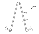
With reference now to Fig. 1,, show one embodiment of the present of invention, wherein, the present invention is used as the room and extrudes mouth.Fig. 1 has described the heart of human subjects." LA " refers to left atrium and " RA " refers to right atrium.The interatrial septum is depicted as 107.The room extrudes mouth 100 and comprises body element 101 and flow control element 104, will describe embodiment in more detail below.Body element 101 comprises flange 102 and 103.In present embodiment as herein described and other embodiment, flange 102 and 103 can be an annular flange, and it limits barrier film 107 and is coupled to gap 2000 wherein.In an embodiment, after inserting, the room extrudes mouth and is located at securely in the opening that produces in the interatrial septum.Arrow F among Fig. 1 illustrates flow direction.Therefore can see by means of device of the present invention pressure among the LA to be gathered and be discharged to RA.
With reference now to Fig. 2,, shows the embodiment that room of the present invention extrudes mouth.The room extrudes mouth 100 and comprises body element 101, and it comprises open basically mesh and comprises columniform basically core section (illustrating with end-view) 106 and annular basically flange 102 and 103. Flange 102 and 103 can be made up of flange section (or " flange component " or " the flange component ") 102a-102h of any number and 103a-103h, and it is attached near the end of core section and radially stretches out from the longitudinal axis of core section and flow control element." flange section " can also be called " supporting leg " in this article.In the disclosed present embodiment of this paper and all embodiment, flange 102 and 103 (with each section 102a-h and the 103a-h that comprise them therefore) can also be in aggregates with the core section.That is to say that it is not necessarily by " attached " with it, but can process by identical materials, this material limit static core section (comprising) with preceding text and mode as herein described, and therefore can adjoin with it.Can for example 105 places be attached to body element with flow control element in the position.Present embodiment and the flange section among any embodiment at any annular flange can be formed by two independent strut members, perhaps can also be formed by discrete component.The flange section on the cross section can be substantially orthogonal, on the cross section be circular, be oval-shaped on the cross section or certain other geometry.
In an embodiment, the flange section is designed to more soft than core section.In this type of embodiment, can realize the flexibility that increases with a plurality of modes.In an embodiment, revise the surface size of the strut members that constitutes the flange section with respect to the corresponding size of the pillar that constitutes the core section (or element, or member).Fig. 2 A illustrates this type of embodiment.Fig. 2 A illustrates the exemplary flange section 103a that the termination is onwards surveyed.As shown in, the strut members of 103x have width D in the face of the size of end.The width that faces outer size through with respect to the pillar that comprises the core section reduces width D, can realize the flexibility with respect to core section or other flange component (or its part) increase flange.The amplification fragment profile of the embodiment that Fig. 2 B illustrates basically at the device shown in Fig. 6.This view is along the line 7-7 intercepting of Fig. 6.In this figure, cross-hatched area illustrates the flexible zone that increases.A zone can seeing the flange section is therefore soft more than another zone.In strut members is circular embodiment, subsequently in a similar fashion, can be so that the diameter of strut members has than comprises the little diameter of diameter of pillar (or like) of the mesh structure of core section.Process and be attached to by the different piece of material among the embodiment of core section at flange component, can this section material be chosen as and have the flexibility bigger (perhaps the remainder of flange itself or flange section depends on the circumstances) than core section.Selecting based on its flexible material will be conspicuous for a person skilled in the art.In the above described manner; The flange section can realize than core section (the perhaps remainder of flange itself or flange section; Depend on the circumstances) bigger flexibility, thus allowing the core section to keep to the strong outward force of barrier film opening and therefore reduce device possibly becoming and reducing the probability that diaphragm tissue is caused damage in the probability of displacement.
At embodiment with the open mesh structure that is used for body element 101; Body element can be formed by the many materials that are suitable in the patient body, using, such as titanium, Nitinol, rustless steel, Elgiloy, mp34n, Vitalium, Mobilium, Ticonium, Platinore, Stellite, tantalum, platinum or other elastomeric material.Alternatively, in this type of embodiment, body element 101 can be by the polymer formation such as PTFE, UHMPE, HDPE, polypropylene, polysulfones or other biocompatible plastics.The surface layer of body element can be slick, does not have edge or sharp being interrupted.In other embodiments, surface layer can have texture to cause tissue reaction and the stability of tissue ingrowth to be improved.In an embodiment; The open mesh of body element 101 can be processed by absorbable polymer, such as polylactic acid, polyglycolic acid, polycaprolactone, both or more combination or well-known multiple other absorbable polymer of those skilled in the art in these.
In an embodiment, the structure of body element can be all even integral body.
In other embodiments; Body element (mesh or integral body) comprises porous material to encourage tissue ingrowth or to serve as the reservoir that is used to comprise one or more chemical compounds, and As time goes on said one or more chemical compounds will be released the many problems that are associated with properties of product to solve after implanting.These chemical compounds can be used for reducing some or all the combination in calcification, proteins deposited, thrombosis or these situation.This chemical compound can also be used to exciting IR to cause tissue ingrowth.In an embodiment, chemical compound can be that antiinflammatory increases with the tissue that prevention is adjacent to device.Many medicaments can be used for this type of all purposes, and are appreciated by those skilled in the art.
Individual in an embodiment; The material that comprises main body can be multiwalled; Comprise absorbable polymer that can comprise all cpds or the coating that partly can pass through polymer, said chemical compound can be released (and in certain embodiments As time goes on controlled way) to solve the many problems that are associated with properties of product after implanting.
Mesh can be formed by tinsel, and it is prebended into the shape of expectation, and combines then to connect said element through adhesively combining with the element welding or with it.Can use resistance welded to finish or the arc welding technology, preferably in being in inert gas environment in and with cooling control with control welding position neutralization grain structure on every side with its welding.After welding procedure, can regulate these points of contact to use punching out or upset reduces granularity so that the fatigue behaviour optimization.
In other embodiments, mesh can be formed by the hollow pipe that uses machine laser instrument for example or rinsing type rig or other method fluting and expand subsequently to form Open architecture.If use material, then can structure be pre-formed into finished form, and then at its strain of delivery period chien shih and loading, therefore, this shape will be recovered flexibly after disposing such as enough elasticity of having of Nitinol and elastic force.The surface of preparing the finished product assembly to guarantee that being passivated and not having surface blemish, surface blemish possibly be thrombotic cradle with taking every caution against error.
In an embodiment, flow control element 104 is the tissue flap such as Tricuspid valve, Bicuspid valve or single lobe, and it is formed by the pericardial tissue from cattle, pig, sheep or other animal.Can use the tip of any number.Use is such as well-known many treatment steps and auxiliary material form flow control element in the art.
Flow control element 104 can also be the valve of spherical valve or other type in discoidal valve, the cage in spherical valve, duck valve, leaflet valve, lamellar valve, the cage; Its combination by polymer or polymer, pottery and metal form, such as terylene, polytetrafluoroethylene, polyurethanes, PET or other suitable polymer; Titanium, rustless steel, Nitinol, MP35N, elgiloy or other suitable metal; Zirconium oxide, silicon nitride or other be pottery suitably.Lobe or its part can comprise the different rigid/flexible character with respect to other lobe in the flow control element or its part.
Flow control element 104 preferably extends to along point of flange assembly 103 so that the salable connection that can after placing, produce septum wall.This wherein, can see in an embodiment that more particularly shown in Fig. 3 flow control element extends beyond the length of core section, and is folded and is attached to the core section, thereby produces the flange that the center position of the opening in the outlet extends.When device abutted against septum wall, this flange formed said salable connection and therefore can reduce blood and possibly go out the outer surface (in the face of membranous surface) of device and the probability that the channel flow between the barrier film opening is crossed the barrier film opening via the room pressure.Flow control element 104 is attached to body element 101.This can realize through using suture material, such as silk, nylon, polypropylene, polyester, gather butyl ester or such as well-known other material of those skilled in the art.In an embodiment, can use such as cyanoacrylate, polymethyl methacrylate or such as the viscosity bonding agent of well-known other material of those skilled in the art flow control element 104 is attached to body element 101.In other embodiments, can flow control element 104 be attached to body element 101 via well-known other similar approach of staple, rivet, ring, clamp or those skilled in the art.
As stated, flow control element can be processed by the material of selecting to its flexibility/stiffness.Expectation more closely with the embodiment of the lax valve of the cyclic resonance of heart in, can select rigid material.When pressure differential reaches selected value, open among the embodiment of valve, can select and/or handle the material of flow control element with the mode that will under the expectation difference, open.The lobule of flow control element itself or section can also comprise the zone of variable hardness, and/or other lobule that can the specific discharge control element or parts are more soft or more not soft.
Fig. 3 illustrates by the device in the interatrial septum of implant patient heart.As can seeing from figure, can with farad 102 with 103 with so flange section 102a-102h and 103a-103h form core section 106 with adjoining respectively.In an illustrated embodiment; Flow control element 104 is comprised in the core section 106; Therefore it does not extend beyond the face of body element 101, thus make its from the isolation that contacts of other agent structure or peripheral organization, in an embodiment; Core section 106 is extended and in the interatrial septum 107 at least one side-prominent interatrial septum 107 and the flange assembly 102 and/or 103 of surpassing, and can be formed with and extend and produce the shape of flange in the above described manner.In an embodiment, the end of flange assembly 102,103 is formed along at least a portion of its length and is positioned at septum wall to become parallel angle and abut against septum wall, thereby to increase contact area and to reduce the stress concentration against septum wall.
With reference now to Fig. 4,, shows the embodiment of body element of the present invention.How this perspective view of body element 101 makes its end become circle with the stress concentration of minimizing after placing against the interatrial septum at far- end 115 and 116 places of flange section 102a-102h, 103a-103h if showing in an embodiment.Can be with this round-shaped part that easily forms the global shape of flange section.In other embodiments, the thickness that can reduce the section in this zone is further to reduce the stress against the interatrial septum, and this is similar to the above embodiments.Be similar to the foregoing description equally,, then can reduce diameter so that increase flexible if this section is circular.And, as stated, can the different materials of high flexibility more be used for the end of each section.
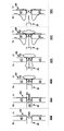
Though the stress on the round-shaped minimizing barrier film at place, the end of flange section it is contemplated that other variant about this theme.Fig. 7 A to 7C illustrates wherein, and the shape of the end of flange section has the embodiment of realization against the structure of the minimizing stress (and other targets) of septum wall.Fig. 7 A is the side elevation view of embodiment that is in the pressure discharger of its mounting structure.Show the core section 106 of body element 101, and in the present embodiment, itself and flange 103 and 102 are in aggregates.Independent flange Duan Wei labels; Yet, can see easily that flange 103 comprises to be substantially similar to above-mentioned those each section.In an illustrated embodiment, there are not eyelet or opening at the place, end of this section.Flange 102 illustrates wherein, and the flange section is not to be made up of but the embodiment of single segment triangle or multiple support layout as described above.Can construct any flange of the present invention with single segment.Exemplary single member is called 103s.In this example, for example, there is eyelet at the place, end of each single member flange section (102s).Fig. 7 B illustrates and the similar embodiment shown in Fig. 7 A, and wherein, the end of section 102s is not an eyelet, but pad.The end that Fig. 7 C illustrates its stage casing 102 is another embodiment of paddle-like.Can use the shape of other smooth edge, and be understood that this type of shape and structure are applicable to all modes of flange section end, are not only single segment.This will comprise that this paper is for example referring to figs. 2 to shown in the 7 and end of described flange section.
Fig. 7 A-C also illustrates the embodiment that has than at least one flange section of other flange segment length.Again, though be represented as single member flange section, it needs not be like this, and likewise, the structure with at least one long section can be applied to the disclosed any flange section structure of this paper.To more fully describe below and have at least one benefit and purpose than the blue section of regular way.
In an embodiment; The outer end of flange section 102a-102h, 103a-103h is formed with overall labeling hole or slit 109 and 110 (for example shown in Fig. 3 and 7); Wherein, can orientate labelling 118 and 119 as feasible can the use such as the radiography imaging device with x ray, magnetic resonance, ultrasound wave or other imaging technique more easily makes device visual.Can be with the disclosed tag application of this paper in any section end, and be not only to have those of hole or eyelet therein.Thereby can flush not passing through radiation labelling 118 and 119 swaged forgings, riveted joint or placement and being fixed in the hole and being sized to the end of this section.Can also be simply labelling be attached to the end of foraminous section of tool not.In having all embodiment of labelling, flange end 115 and 116 is visible more by imaging the time.In other embodiments, can labelling 118 and 119 be combined, such as cyanoacrylate or epoxy resin or well-known available and multiple other material of being suitable for implanting with binding agent.Labelling can be (shown in for example Fig. 7) of protuberance or flush with the end of flange section.Not passing through radiation labelling 118 and 119 can be formed by alloy or known other material of those skilled in the art of tantalum, tungsten, platinum, iridium, gold, these materials.And; Can be with the labelling 118 and 119 that does not pass through radiative material or combination comprises perhaps many other paramagnetic materials of cobalt, fluorine or other MR visible material known to those skilled in the art on the alternate position of flange section, so that can realize that the x ray and the MR of room extrusion mouth form images both.Alternatively, can twine the end of flange component 102a-102h and 103a-103h with the paper tinsel of processing by the same tag material.In an embodiment, can with do not pass through radiative material be laminated to the flange section and through welding process or use such as cyanoacrylate or those skilled in the art the binding agent of known many other binding agents it is combined.
Can in body element, form suture ring 117 with along body element with attachment point location and be fixed in flow control element.Suture ring can be the circular port that is formed in the structure; Perhaps it can also be such as rectangle or leg-of-mutton certain other shape, and can be used as additional step and for example form with standard mechanical process technology, use auxiliary laser procedure of processing or use chemical etching.Preferably, with big as far as possible diameter form one section of body element with any other section between be connected with the resistance of increase fatigue rupture.And, preferably, make all edges of the device of formation become circle to improve biocompatibility and blood compatibility.
The pattern of suture ring and during sewing up, select which ring can influence the character of flow control element.For example, make among the lax and embodiment that can swing of flow control element, can utilize less suture ring, and in this type of embodiment, the RA side end of flow control element can comprise the stitching thread that lacks relatively than the LA side in expectation.In other embodiments, the interior flow control element that keeps of length that possibly be desirably in the section of increase is attached to the core section, thereby reduces the amount of the mobile flow control element material of influence.In other embodiments, can influence top or the base section that mobile mode is sewn to the flow element of RA side more than other another part respectively with top or the base section that allows flow control element.Wherein the embodiment that discussed by the hereinafter of " orientation " of flow can effectively utilize suture pattern and make it possible to realize the flow control element structure expected.
Return the flange section, in an embodiment, the room extrudes mouthfuls 100 and is made up of the flange section at the equal number of each side of interatrial septum.In an embodiment, there are eight flange sections in the every side in the core section.On the other hand, there be the suture ring and the flange section of equal number in a side that extrudes in the room mouthful.In other embodiments, there are seven flange sections in the every side in the core section.In other embodiments, there are six flange sections in the every side in the core section.In other embodiments, there are five flange sections in the every side in the core section.In other embodiments, there are four flange sections in the every side in the core section.In other embodiments, there are three flange sections in the every side in the core section.In other embodiments, there are two flange sections in the every side in the core section.In other embodiments, there is a flange section in the every side in the core section.In other embodiments, compare with the farad section and have more flange section.And in other embodiments, compare the more flange sections of existence with the flange section.As can see, can exist to be used for the many variations of flange hop count purpose, the technical staff will recognize do not depart from the scope of the present invention with spirit in can use any number.
With reference now to Fig. 5,, in side view shows the body element of embodiments of the invention.Can the flange section be formed when device and be in its " nature " or not during deployable state, between the end of the flange section of the flange section of a side of main body and main body opposite side, produce clearance G (being also referred to as the annular gap).When having disposed device, its bending is to hold tissue, and likewise, when tissue was arranged in the gap, the gap can be expanded.In an embodiment, this gap is slightly less than the thickness of interatrial septum.In other embodiments, the gap can be greater than the thickness of interatrial septum.In other embodiments, the gap can be zero.On the other hand, the gap can be minus; In this case, can the flange section in each side of main body be formed mutual intersection, so that between flange section of disposing and interatrial septum, have more multiple pressure power.Also illustrate among Fig. 5 and do not pass through radiation labelling 118 and 119, it is illustrated as and is positioned at the place, end that is adjacent to the flange section in an embodiment.
With reference now to embodiment shown in Figure 6,, flange section 102a-102h is oriented and makes it directly relative with flange section 103a-103h at the opposite side of body element, makes after placing, and does not have fulcrum, thereby reduces the probability of tissue injury.In an embodiment, flange section 102a-102h is arranged between the adjacent end portion of flange section 103a-103h.In an embodiment, the length of flange section 102a-102h is similar to the length of flange section 103a-103h.Yet in other embodiments, the length of flange section 102a-102h is identical with the length of flange section 103a-103h; The length of flange section 102a-102h is longer than 103a-103h; And the length of flange section 102a-102h is shorter than flange section 103a-103h.
With reference now to Fig. 7; In having not the embodiment that passes through the radiation labelling, can see can be with not passing through that radiation labelling 118 and 119 is placed in index aperture 109 and 110 (or being placed on the end of the foraminous flange section of tool not) so that during this program or use non-intrusion type imaging technique (such as with x ray or MRI) that the end of flange section 102a-102h and 103a-103h is positioned afterwards.In an embodiment, can labelling 118 and 119 be formed along axial direction and flush with outer surface and the inner surface of flange section 102a-102h and 103a-103h.On the other hand, can labelling 118 and 119 be formed the outer surface that extends beyond flange section 102a-102h and 103a-103h along axial direction, away from the interatrial septum.In an embodiment, can labelling 118 and 119 be formed the inside that extends beyond flange section 102a-102h and 103a-103h along axial direction, towards the interatrial septum.In an embodiment, can labelling 118 and 119 be formed along axial direction and extend beyond the inside and outside of flange section 102a-102h and 103a-103h.In an embodiment, can form along axial direction labelling 118 and 119 sunken at the concave surface of the inside of flange section 102a-102h and 103a-103h.In an embodiment, can labelling 118 and 119 be formed along the external concavity of axial direction at flange section 102a-102h and 103a-103h.In an embodiment, can labelling 118 and 119 be formed along axial direction inside and outside both sunken insides at flange section 102a-102h and 103a-103h.In an embodiment, can labelling 118 and 119 be formed along axial direction and in the width of flange section 102a-102h and 103a-103h, extend.In an embodiment, can labelling 118 and 119 be formed along axial direction extend with flushing with the width of flange section 102a-102h and 103a-103h.
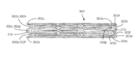
With reference now to Fig. 8,, shows room of the present invention with its mounting structure and extrude mouth 100.In an embodiment, can make the room extrude mouth and be crimped to basically cylindrical shape so that between resting period, be loaded in the delivery conduit.Can be fabricated on length flange section 102a-102h and 103a-103h equal basically." " loaded " position " is not intended only to be applied to have the device of the flange section of equal length, and is applied to all embodiment of the disclosed discharger of this paper.Have such as those the device of flange section of variation length and orientation described herein and also be designed to load with substantially the same mode shown in Figure 8.Among the embodiment 200 that in Figure 20, sees, on the angle of inclination, form flange section 202a-202h and 203a-203h, make when identification element is fixed in the end of flange section, can the flange section be loaded in the smaller volume.Among the embodiment 300 that in Figure 21, sees, flange section 302a-302h is formed with alternative length and is loaded in the smaller size smaller allowing.
With reference now to Fig. 9,, on open position, shows the embodiment of the far-end of placement conduit 111 of the present invention.In center cavity 136, make interior axle 112 with the diameter that is enough to comprise lead 138 or also supplies when injecting contrast agent or other liquid, to use.Usually, should be to 0.010 the lead of ", 0.011 ", 0.014 ", 0.018 ", 0.021 ", 0.028 ", 0.035 ", 0.038 ", 0.042 " or 0.045 " confirm the size in chamber.Can also use well-known miscellaneous equipment of those skilled in the art and technology, use this chamber 136 to come the pressure of the far-end of measuring guide.The whole length of axle 112 in chamber 136 preferably extends through.Alternatively, guidewire lumen 136 can be extended the side opening (not shown) that short length is also passed through inner sheath subsequently along proximal direction.The corresponding side opening (not shown) of on outer shaft 113, placing the side opening in the axle 112 in being adjacent to is to produce passage between the outside of interior 112 center cavity 136 and outer shaft 113.Like this, can make lead from the far-end of inner chamber 136 through side opening and in fixing cord position between commutation period with conduit and lead exchange than the little twice of length of conduit 111.
In an embodiment, be constructed with lumbar region section 120 for interior 112 and extrude mouth 100 with the folding room between the inside of gap in the space that is included in this section outside that is formed at interior axle 112 and outer shaft 113.Can the proximal end that interior axle 112 forms the section 120 in the lumbar region be comprised at least one circumferential groove 114; It forms pit between the minimum diameter of the inside of outer shaft 113 and groove, this minimum diameter is greater than the gap that forms in the space between the inside of lumbar region section 120 and outer shaft 113.Do not pass through the outer surface that radiation labelling 118 can extend through flange section 102a-102h along radial direction; And in an embodiment; When room of the present invention extrude mouthful be folded into its mounting structure and be placed in during position on the axle 112, radiation labelling 118 is sized to and is coupled in the groove 114 thoroughly.Can use the section of other similar size; That is, be coupled to the radiation labelling thoroughly that is not necessarily not in the groove.In an embodiment; When loading room of the present invention by this way and extrude mouthful; Gap between the inside of lumbar region section 120 and outer shaft 113 is not enough to allow not pass through the far-end that radiation labelling 118 surpasses groove 114, only if oversheath 113 is contracted the near-end above groove 114.
In axle 112 can on the far-end of lumbar region section 120, to be formed with the position that groove 121 is adjacent to the far-end that room of the present invention extrudes mouthful be not pass through the outer surface that radiation labelling 119 (or member of similar definite size) can extend beyond flange section 102a-102h along radial direction; And in an embodiment; When room of the present invention extrude mouthful be folded into its mounting structure and be placed on the position on the axle 112 time, radiation labelling 119 is sized to and is coupled in the groove 121 thoroughly.On the other hand, interior axle 112 can be formed with at circumferential groove on the near-end of lumbar region section 120 114 and the circumferential groove on the far-end of lumbar region section 120 121.Interior axle can being combined to form by the multiple polymers that is suitable in the patient body, using or metal or polymer and metal.Interior axle can be processed by an one end PTFE, UHMWPE, FEP, HDPE, LDPE, polypropylene, acetal, Delrin, nylon, Pebax, other thermoplastic rubber, aliphatic or aromatic urethane or well-known multiple other engineering resin of those skilled in the art.In an embodiment, can use a plurality of layers of two or three in the above-mentioned polymer to make interior axle with desirable properties combination with every kind of polymer.For example, outer surface can be made up of so that can realize the easier combination of accessory to interior axle polyurethane.Liner can be that PTFE transmits better lubricity with inside axle.In an embodiment, can with coating material on interior and/or outer surface internally axle and/or outer shaft apply, it transmits the special properties such as antithrombotic or lubricity to axle.There is the well-known many available coating material that is suitable for these purposes of those skilled in the art.In axle can be mixed with radiation opaque agent (radiopacifier) and increase interior observability fluoroscopy under, said bismuth salt such as bismuth subcarbonate, bismuth oxychloride, bismuth oxide, tungsten powder, molybdenum powder or such as well-known other antiradiation agent of those skilled in the art to use bismuth salt.Likewise, can be by the one group material identical with inner sheath, in an identical manner and use identical coating to make oversheath.The embodiment that describes below in conjunction with flange rather than circumferential groove to be operating with preceding text and substantially the same mode described herein, different is excrescence that device not necessarily has to be coupled in the groove and to be kept by groove.
With reference now to Figure 10., on its " loaded " position, show folding typical room of the present invention and extrude mouth 110, on open position, show placement conduit 111 of the present invention.In fact; If the room extrudes the main body of mouth and is processed by Nitinol or other elastomeric material; Then when the placement conduit is in its fully open position; Flange section 102a-102h and 103a-103h will automatically return to and for example be similar in the shape shown in Fig. 4, and therefore, it is in order to explain that the room extrudes mouthful 100 positions with respect to lumbar region section 120 and groove 114 and 121 that this figure is shown.When not passing through the radiation labelling member of size (or likewise confirm) 118 and extend beyond the room and extrude the thickness of inside of mouthfuls 100 main paragraph 101; It extrudes in mouthfuls 100 in the room and forms excrescence, and this excrescence can be trapped in the groove 114 with the fixing position of room extrusion mouth 100 between resting period.During disposing, the outer shaft 113 of placing conduit 111 is contracted enough distances to expose the distal part that the room extrudes mouth 100, allows the central longitudinal axis radially diastole of flange section 103a-103h away from main body 101.Be captured in the groove 114 through will not passing through radiation labelling 118; Can easily reorientate under the situation of further disposing not having device, perhaps can as Figure 17 indicated not have to make under the situation of disposing device to withdraw fully and from patient's health removal.
With reference now to Figure 11,, shows the room of the present invention that is loaded in fully by in the placement conduit 111 of the present invention and extrude mouth 100.
Figure 11 A illustrate be similar in operation as herein described those but can operate and be used for via combining the described slightly different mechanism of circumferential groove to engage the embodiment of the placement conduit that the room extrudes mouthful with preceding text.This illustrates and loads the schematic depiction that the room extrudes mouth.As having substituting of aforesaid groove, the present embodiment of placing conduit comprises interior axle, and it has flange or member 3000 (rather than groove), and it has than the big diameter of the diameter of interior axle to clamp and to keep the end of room pressure device as shown.Shown in figure, flange and each section thereof (jointly being called 102 in the drawings) are around spherical flange 300 and allow the room to extrude mouthful with mode as herein described along with apparatus for placing is mobile together.
With reference now to Figure 12,, shows placement conduit 111 of the present invention.Though it should be noted in Figure 12 interior axle is depicted as to have groove, interior axle can comprise like preceding text and combines the described flange 3000 of Figure 11 A.The technical staff will recognize no matter the operation of device, be to use groove or flange if being similarly basically.Place conduit 111 and comprise first in command's parts 128 that can be attached to outer shaft 113.Can use multiple sticky method that first in command's parts are attached to outer shaft 113, such as the solvent combination of the solvent that uses handle and outer shaft material; The organosol of forming by solvent and polymer in the solution compatible with first in command's parts with outer shaft; Polymerizable binder is such as well-known multiple other binding agent of polyurethane, cyanogen acrylic acid ester, epoxy resin or those skilled in the art.First in command's parts can be processed by multiple metal, such as well-known many other metals of aluminum, rustless steel, titanium or those skilled in the art and alloy.In an embodiment, first in command's parts 128 are by processing such as the polymer of Merlon or such as various engineering resin or well-known other project of those skilled in the art of Lexan.First in command's parts comprise handle section 124 and tubular shafts section 125.Tubular shafts section 125 can comprise the keyway 122 that is formed or is machined in the section.This keyway preferably is formed with three linear segments: first linear segments 131, second linear segments 132 and the trilinear section 133.In these sections each is formed along mainly passing along the length of the first in command's parts path parallel with central axis, but each each other radially the shift key well width at least about half the.Place conduit 111 and can also comprise second in command's parts 129 that can be attached to inner sheath 112.Second in command's parts can be by processing with the metal and the polymer of first in command's parts identical type.Two grip can or be made from a variety of materials by identical materials.Can and use identical materials that the second in command is attached to inner sheath with the mode identical with the first in command's parts that are attached to oversheath.In an embodiment, second in command's parts can comprise the screwed hole 126 that is used to comprise dog screw 127.Can make the dog screw distortion catch interior axle to abut against second in command's parts.Second in command's parts 129 can also comprise the second handle section 134 and the second tubular shafts section 130.The second tubular shafts section can comprise and is formed or machining is to have the key 123 of appropriate size with the keyway 122 that is suitable for first in command's parts 128.When assembling, can be second in command's parts 129 be moved slidably with respect to first in command's parts 128 by the shape of keyway 122 and the mode of length control.Along with the second in command 129 advances with respect to the first in command 128, can recognize that inner sheath 112 will slide along the distal direction of coming out from oversheath 113.Can recognize that key 123 slides in first linear segments 131 and advances, and bumps against the edge of the keyway that between first linear segments 131 and second linear segments 132, forms until it when assembling second in command parts 129.For second in command's parts 129 are advanced further, in a single day must make its rotation, and be rotated, it is advanced further, but will when key 123 bumps against the edge of the keyway that between second linear segments 132 and trilinear section 133, forms, stops.Preferably select the keyway size under the situation of the combination of the length of other parts in considering apparatus for placing.Preferably confirm primary importance; It is defined as the position of the proximal that forms between key 123 and first linear segments 131 and second linear segments 132 when contacting; Make and mouthful to place when being in its " loaded " position in the conduit that outer shaft 113 will cover the length that the room extrudes mouth 100 at conduit between resting period fully as expectation when being extruded by assembling and room fully.Can also keyway be sized to and cause the second position, it is defined as the position of the distal side edge that forms between key 123 and second linear segments 132 and the trilinear section 133 when contacting.The second position will be preferably selected to be the total length of exposing flange section 103a-103h, but flange section 102a-102h is remained in the outer shaft 113 of conduit.The length of trilinear section 133 will preferably be selected as and make when second in command's parts 129 abut against first in command's parts 128 fully and advance, and the room extrudes mouthfuls 100 total length will be by outer shaft 113 exposures, and this device can be disposed.Can multiple other of first and second grip members be configured to this purpose.Can the tubular shafts section 125 of first in command's parts and the tubular shafts section 130 tapping (not shown) of second in command's parts be made and can first in command's parts 128 be tightened to second in command's parts 129 with screw.Alternatively, can be in the first tubular shafts section 125 of first in command's parts 128 formative gear tooth (not shown), and can the gear (not shown) be attached in second tube 130 of second in command's parts 129.Gear will be preferably selected to be with gear teeth and be meshed, and can second in command's parts 129 advanced towards first in command's parts 128 through swing pinion.Well-known like those skilled in the art, can utilize multiple other design structure to control the relative position between first in command's parts and the second in command's parts.
Figure 13 to 17 shows the system implementation example that is used to treat heart failure of the present invention.More specifically, Figure 12 to 19 shows how to introduce and places conduit and be positioned in the patient body and be used for the room valve is placed on the intravital method of patient.The room extrudes mouthful 100 quilts sterilization in advance and packs dividually with placement conduit 111.Can through make device be exposed to sterilizing gas (such as oxirane), through making device be exposed to high temperature to reach abundant length time period, through use ionizing radiation (such as gamma-rays or electron beam) or through device is immersed in chemically making the crosslinked fluid of organic molecule (such as formaldehyde or glutaraldehyde) and subsequently in sterilized water or aseptic salt rinsing carry out sterilization.For in these sterilization methods each, must consider the compatibility of material, make that the appliance arrangement performance can be owing to disinfecting process affects adversely.And, must be with the carrying during disinfectant program, the carrying of sterilization back and storage, storage and the environmental exposure between the time of shipment and this program, open, appear and use easy property to consider package design and material.
In an embodiment, can use of having used in the said method or well-known other method in advance the disinfectant parts assemble the room and extrude mouthfuls 100, and can realize that final assembling pollutes avoiding with sterile manner.
In an embodiment, can supply the room non-sterilely extrude mouthfuls 100 and use in the said method one or carry out disinfection about the time of use greatly with well-known other method of those skilled in the art.
Likewise, can pack dividually placing that conduit 111 sterilize in advance and extruding mouthfuls 100 with the room.Can use with room extrusion mouthful 100 similar methods or use and carry out sterilization from distinct methods or well-known certain other method of use those skilled in the art of identical selection.
In an embodiment, can supply the room with sterilization in advance and the mode in same packing extrudes mouth 100 and places conduit 111.On the other hand, can the room be extruded mouth 100 and supply with placing conduit 111 prestrains and sterilization in advance.
Before inserting, preferably make the room extrude mouth 100 and fold and be loaded on the placement conduit 111.This can or use aseptic technique in following steps, to realize in the sterilization scene.At first, also will place conduit 111 presents to aseptic scene room extrusion mouth 100 to be presented to aseptic scene.Secondly, the visible sign inspection room to damage, deterioration or pollution extrudes mouth 100 and places conduit 111.The 3rd, second in command's parts 129 of placing conduit 111 are withdrawn fully, make outer shaft 113 make interior axle 112 be exposed to permission at utmost.The 4th, the room is extruded mouthfuls 100 correct orientations that are positioned to place on the interior axle 113 of conduit 111, the center that interior axle 113 is oriented through flow control element 104.The 5th; Flange section 102a-h and 103a-h are folded up each other; And radially compressing flange section 102a-h and 103a-h so that the room extrudes mouthfuls 100 is folded on the lumbar region section 120 of axle 112 in being engaged in and be coupled to the size and dimension above it, the far-end 115 of flange section 102a-h is aimed at interior 112 proximal flutes 114.In the embodiment that comprises the flange shown in Figure 11 A; Flange section 102a-h and 103a-h are folded up each other, and flange section 102a-h and 103a-h and core section 106 by compression radially so that the room extrudes mouthfuls 100 is folded into the size and dimension on the flange 3000 that is engaged in description Figure 11 A on.Can realize under the help of the instrument of insertion (not shown) that this is folding; This insertion instrument extrudes mouth 100 with the room and remains on the " loaded " position on the interior axle 112; And outer shaft is extruded in the room that loads advance on mouthfuls 100 and make the displacement of insertion instrument, extrude mouthfuls 100 and cooperate thereby make outer shaft 113 cover the room fully with the distally cone point 140 of interior axle 112.In other embodiments, the appropriate location at groove 114 places of axle 112 and outer shaft 113 is advanced to be enough to that flange section 102a-102h is remained on original position on interior axle 112 and come to realize in this finger that can use a hands remains on the far-end 115 of flange section 102a-102h with hands.Through outer shaft 113 little by little being advanced, shown in Figure 11 and 11A, covering the completion that room extrusion mouth 100 is realized loading procedure fully until it.Though the following discussion of the placement that extrudes mouthful about the room use shown in 9-11 apparatus for placing as an example, about place with the cat Mus of program therefore also intended use in wherein, spool comprise the embodiment of flange rather than groove.
Can be embodied as loading room valve of preparing in the room valve 100 implant patient bodies 100 and the location of placing conduit 111 through the following: at first near vascular; Secondly, lead 121 is placed in patient's the right atrium; The 3rd, the conductor (not shown) is positioned in patient's right atrium; The 4th, confirm the position of interatrial septum; The 5th, make conductor advance and get into patient's left atrium through the interatrial septum; The 6th, lead 138 is advanced in the left atrium; The 7th, make the conductor withdrawal; The 8th, the placement conduit 111 that makes loading and room extrude mouthfuls 100 and advance to the appropriate location, make the room extrude in the half the and entering patient's outstanding through the interatrial septum of the pact of mouthfuls 100 far-end and cargo length the left atrium, and be shown in figure 13.
In an embodiment, can be embodied as room valve 100 and the location of placing conduit 111 through the following: at first near vascular with the loading of preparing in the room valve 100 implant patient bodies; Secondly, lead 121 is placed in patient's the right atrium; The 3rd, through lead being inserted in the chamber 136 and through chamber 136 and make and place right atrium that conduit 111 advances to patient and make and load room valve 100 and place conduit 111 and on lead 138, advance; The 4th, confirm the position of interatrial septum, the 5th, make conductor advance and get into patient's left atrium through the interatrial septum, make the room extrude in the half the and entering patient's outstanding of the pact of mouthfuls 100 far-end and cargo length the left atrium through the interatrial septum, shown in figure 13.
In case loading the room extrudes mouth 100 and places conduit 111 in place; Can realize the room is extruded in mouthful 100 implant patient bodies through the following; At first; When keeping second in command's parts 129, make first in command's parts 128 towards 129 withdrawals of second in command's parts, exposed fully as illustrated in fig. 15 until flange section 103a-h, and can be through using fluoroscopy or MRI or using echocardiography to make labelling 119 visual testing; Secondly; Make and place conduit 111 and the room of partly disposing and extrude mouthfuls 100 and withdraw towards patient's right atrium; Until the left room of flange section 103a-h and interatrial septum side contacts; Shown in figure 16, and can use described constructed the check perhaps to come perception based on moving the resistance of feeling by the user to the farther nearside of placing conduit 111; The 4th, through being retracted, the second in command 129 continues to make oversheath 113 withdrawals, be contracted the near-end of the groove 114 that surpasses interior axle 112 until outer cover 113; And flange section 102a-h is exposed; At this moment, the flange section 102a-h that the room extrudes mouth 100 will dispose, and be back to the prestrain geometry; And between flange section 103a-h and flange section 102a-h, catch the interatrial septum, shown in figure 18; The 5th, inner sheath is retracted in patient's right atrium through the flow control element 104 that the room extrudes mouth 100, shown in figure 19; The 5th, second in command's parts 129 are advanced so that interior axle 112 is re-positioned at its residing position with respect to outer shaft 113 between resting period towards first in command's parts 128, and remove from patient's health and to place conduit and to accomplish this program.
In other embodiments; In case loading the room extrudes mouth 100 and places conduit 111 in place; Can realize the room is extruded in mouthful 100 implant patient bodies through the following, at first, when keeping first in command's parts 128, make second in command's parts 129 towards 130 withdrawals of first in command's parts; Exposed fully as illustrated in fig. 15 until flange section 103a-h, and can be through using fluoroscopy or MRI or using echocardiography to make labelling 119 visual testing; Secondly; Make and place conduit 111 and the room of partly disposing and extrude mouthfuls 100 and withdraw towards patient's right atrium; Until the left room of flange section 103a-h and interatrial septum side contacts; Shown in figure 16, and can use described constructed the check perhaps to come perception based on moving the resistance of feeling by the user to the farther nearside of placing conduit 111; The 4th, through being retracted, the second in command 129 continues to make oversheath 113 withdrawals, be contracted the near-end of the groove 114 that surpasses interior axle 112 until outer cover 113; And flange section 102a-h is exposed; At this moment, the flange section 102a-h that the room extrudes mouth 100 will dispose, and be back to the prestrain geometry; And between flange section 103a-h and flange section 102a-h, catch the interatrial septum, shown in figure 18; The 5th, inner sheath is retracted in patient's right atrium through the flow control element 104 that the room extrudes mouth 100, shown in figure 19; The 5th, second in command's parts 129 are advanced so that interior axle 112 is re-positioned at its residing position with respect to outer shaft 113 between resting period towards first in command's parts 128, and remove from patient's health and to place conduit and to accomplish this program.
For various reasons, possibly need or be desirably in not during any part of this program, remove under the situation to patient's further risk or injury the room extrude mouthfuls 100 with place conduit 111.This is possible, as follows: if owing to any reason, be desirably in outer shaft 113 withdrawal and dispose removal device before the flange section 103a-h, then can make placement conduit 111 with room valve 100 contract out through identical passage when being introduced into simply.
If after the deployment of flange section 103a-h, need or the expectation removal device; Then can place in the conduit 111, thereby ground, oversheath 113 distally is advanced through the interatrial septum and on flange section 103a-h through making the first in command 128 advance, keep simultaneously the second in command's 128 differences that room valve 100 is withdrawn into away from the second in command 128.In an embodiment; The radiation labelling 118 that do not pass through that is placed in the index aperture 109 is trapped in (referring to Figure 17) in the groove 114; And in the gap in it can not be engaged between the inner surface of the lumbar region section 120 of axle 112 and outer shaft 113; As long as oversheath 113 is advanced, force flange section 103a-h inwardly folding, and be withdrawn in the interior axle 112 and in the oversheath 113 towards its " loaded " position.In case outer shaft 113 advances fully, conduit 111 is withdrawn so that remove and remove through identical passage when being introduced into through the interatrial septum as illustrated in fig. 17.
Figure 19 A is the embodiments of the invention that are designed to the retrieval property of intensifier.Be used for the program of implanting device and mentioned above substantially similar; Yet, the change that exists hereinafter to describe to placement conduit and device.As combining Fig. 7 A to 7C to be discussed, the embodiment of room discharger comprises at least one the flange section than other flange segment length.The embodiment of Figure 19 A shown in schematically preferably is suitable for this type of embodiment with at least one flange section longer with respect to other flange Duan Eryan; Therefore, each section shown in Figure 19 A has and the identical Reference numeral of long section in Fig. 7 A to 7C, i.e. a 102L.In the embodiment that utilizes the technology shown in Figure 19 A, the opening 113a that places the oversheath 113 of conduit is angled, and has more surface area for opposite side in a side.Placing conduit is oriented during this program and makes have angle opening (or plane of opening itself) to be in more the angle perpendicular to septum wall 107.In the embodiment shown in Figure 19 A; This angle seems to be about 45 degree with respect to septum wall 107; But can use any angle that provides with respect to the more normal angled of septum wall, and can use any opening that the surface area of more oversheath 113 for opposite side is provided in a side.Reference numeral 4000 to 4050 is with reference to the step in the following process.This process is similar to mentioned above to a great extent, perhaps for any well-known placement conduit system and process, therefore, advances to describe difference applicatory.Like what can see, to placing that conduit positions and device is in the initial period of deployment at step 4000 to 4020 places.At step 4030 and 4040 places; When oversheath 113 be contracted and on the RA side time (perhaps when before the interior axle and then when oversheath is on the RA side simultaneously; This is not shown), opening allows to dispose other flange section and therefore with after barrier film 107 contact it dispose than one among the regular way orchid section 102L.At least one is maintained at by means of oversheath 113 than the blue section of regular way 102L and places in the conduit system; The length of oversheath 113 since opening and in a side than extending fartherly at opposite side, and therefore when having disposed other short section, cover long section 102L.Like this, the operator who places conduit can confirm whether room device is in the appropriate location.If no, then the operator still can retrieval device, the last moment before disposing fully, that is, and when at least one (for example 102L) in the blue section than regular way still remained on by oversheath 113 in the placement conduit.If it is in the appropriate location, then can begin to dispose.
Combine Figure 19 B to describe another now and dispose embodiment.This disposes embodiment can be used for any embodiment that room as herein described extrudes mouth.Reference numeral 5000 to 5050 is with reference to the step in the following process.At step 5000 place, in the LA side (being commonly referred to as 100 in the drawings) of the LA of heart sidepiece administration device.Show further deployment at step 5010 place, and oversheath is retracted in the RA side of heart, this allows flow control element 104 to withdraw from the placement conduit.Place catheter cartridge and be furnished with air bag, it for example carries out fluid with above-mentioned chamber 135 or lead 138 and is communicated with.The technical staff will be appreciated that other structure that balloon catheter wherein can be provided in placing conduit system.When the deployment of LC side flange or thereafter soon, to air bag 130 inflations (place illustrates in step 5020).Abut against the LA side holding device 100 of septum wall 107 alternatively with the inflation that retracts the coupled air bag of motion of placing conduit 111, thereby and anti-locking apparatus 100 during disposing, be shifted and/or move along direction away from septum wall.The deployment fully of the device 100 when step 5040 illustrates air bag 139 and is inflated.After having realized gratifying deployment, placement conduit system (place illustrates in step 5050) is abandoned and removed to air bag 139.
With reference now to Figure 20,, shows room of the present invention and extrude mouth 200.In an embodiment, flange section 202a-h and 203a-h can be formed with the length that gradually changes to reduce in carrying, folding and the flange section 202a-h of loading duration and the interference between the 203a-h.In an embodiment, do not pass through radiation labelling 218 and 219 and be projected in the inner cylinder shape of the " loaded " position that the room extrudes mouthful, and each flange section 202a-h and 203a-h differ at least the width of radiation labelling 218 thoroughly and 219 aspect length.In an embodiment, each flange section 202a-h and 203a-h differ 1mm at least aspect length.In an embodiment, each flange section 202a-h and 203a-h differ the room that is in position shown in Figure 20 and extrude at least 2% of mouthfuls 200 total length aspect length.
With reference now to Figure 21,, shows room of the present invention and extrude mouth 300.In an embodiment, flange section 302a-h and 303a-h can be formed with and replace length to reduce in carrying, folding and the flange section 202a-h of loading duration and the interference between the 203a-h.In an embodiment; Not passing through radiation labelling 318 and 319 is projected in the inner cylinder shape of " loaded " position that the room extrudes mouth 300; And alternative flange section 302a, c, e and g are than flange section 302b, d, f and h field; And correspondingly, flange section 303b, d, f and h have grown the width that does not pass through the radiation labelling at least than flange section 303a, c, e and g.In an embodiment, alternately flange section 302a, c, e and g are longer than flange section 302b, d, f and h, and correspondingly, flange section 303b, d, f and h have grown 1mm at least than flange section 303a, c, e and g.On the one hand, alternately flange section 302a, c, e and g are longer than flange section 302b, d, f and h, and correspondingly, and flange section 303b, d, f and h have grown the room that is in position shown in Figure 21 than flange section 303a, c, e and g and extruded at least 2% of mouthfuls 300 total length.
With reference now to Figure 22 and Figure 23,, show the body element 401 with whole thrombus filter and room extrusion mouth of fetching cone 442 of the present invention.In an embodiment, conical pillar 444 is attached to body element 401 at attachment point 446 places and the 450 places convergence on the summit.In an embodiment; Conical pillar 444 comprises and flange section 402 and 403 similar single strands of material; And it is can use the technology described in this description to be attached to body element or side by side form, and therefore in aggregates with the remainder of device with body element.In an embodiment, the space between the adjacent struts 444 is about 2mm.In an embodiment; Space between the adjacent struts 444 is about 4mm such as cognoscible; Conical pillar 444 will be projected in patient's the right atrium after implanting, and the space between the conical pillar will be used to organize passing through of the solid material bigger than the space between the adjacent struts 444.This will provide and prevent that the thromboembolism bigger than the space between the adjacent struts 444 from passing through to the function of left atrium from right atrium.
Refer again to Figure 22 and Figure 23, in an embodiment, the shape of conical pillar 444 is not straight.In an embodiment, when on like the end that Figure 22 described, seeing, the shape of conical pillar 444 can cave in.In an embodiment, can make conical pillar crooked along direction away from the string that between summit 450 and attachment point 446, forms.In an embodiment, can there be the hole 451 of fetching lasso (snare) (not shown) even as big as reception through summit 450.Can recognize that conical pillar 444 and summit 450 can extrude mouthful with helping to use following method certain time after implant procedure in the patient body, to fetch the room: the conduit that can use standard technique and imaging device will have at least the same big inner chamber with summit 450 is placed into patient's right atrium.Fetching lasso can be processed by the near-end of lead of crooked about 180 degree sharp; And can insert its lasso and make its right atrium that advances to patient through conduit, and be to advance through controlling 451 or under the help of the fluoroscopy around the conical pillar 444.Fetch lasso in case engaged by this way, come in to make the room to extrude a mouthful withdrawal before then can making conduit simultaneously through slight tensile on keeping lasso, thereby and on the summit 450 with catheter guidance extremely on the conical pillar 444.Along with conduit moves on, on lasso, have certain force of strain, can force conical pillar inside, thereby force 402 beginnings of flange section inwardly folding.When conical pillar almost completely when the spectators, can conduit be remained on the fixed position and make the lasso tinsel abut against the conduit withdrawal, thereby impel the attachment point 446 between conical pillar 444 and the flange section 402 to be withdrawn in the conduit.Flange section 402 can be put once more and begin to be withdrawn in the conduit, and the far-end of flange section 402 is shifted towards patient's left atrium, but still inwardly is folded and arranged into conduit.In case flange section 402 in catheter interior, then can keep lasso to fix, and conduit is advanced further through the interatrial septum and on flange section 403.In case flange section 403 is withdrawn in the conduit, then can conduit and lasso be come along and remove, so that the room extrudes in the right atrium that mouth is withdrawn into patient and through passage, it is introduced through this passage.
With reference now to Figure 24 and 25,, show the alternative embodiment that the room extrudes mouth 500.In an embodiment, flow control element 504 is made up of lobule 541a-c.Body element 501 constitutes (not exclusively visible in Figure 25) by core section 506 with flange section 502a-l and 503a-l; The number of flange section is the multiple of lobule number.This structure has improved the strained symmetry to the flow-control lobule, and has improved the motion of flow control element and the concordance that blood flow changes.
In an embodiment, the number that comprises the lobule of flow control element is three, and is 12 at the number of the flange section of every side of core section.In an embodiment, the number that comprises the lobule of flow control element is three, and is nine at the number of the flange section of every side of core section.In an embodiment, the number that comprises the lobule of flow control element is three, and is six at the number of the flange section of every side.
In an embodiment, the number that comprises the lobule of flow control element is three, and is three at the number of the flange section of every side.In an embodiment, the number that comprises the lobule of flow control element is three, is 12 at the number of the flange section of a side of core section, and is nine at the number of the flange section of the opposite side of core section.In an embodiment, the number that comprises the lobule of flow control element is three, is 12 at the number of the flange section of a side of core section, and is six at the number of the flange section of the opposite side of core section.
In an embodiment, the number that comprises the lobule of flow control element is three, is 12 at the number of the flange section of a side of core section, and is three at the number of the flange section of the opposite side of core section.In an embodiment, the number that comprises the lobule of flow control element is three, is nine at the number of the flange section of a side of core section, and is six at the number of the flange section of the opposite side of core section.In an embodiment, the number that comprises the lobule of flow control element is three, is nine at the number of the flange section of a side of core section, and is three at the number of the flange section of the opposite side of core section.
In an embodiment, the number that comprises the lobule of flow control element is three, is nine at the number of the flange section of a side of core section, and is three at the number of the flange section of the opposite side of core section.In an embodiment, the number that comprises the lobule of flow control element is two, and is 12 at the number of the flange section of every side of core section.In an embodiment, the number that comprises the lobule of flow control element is two, and is ten at the number of the flange section of every side of core section.In an embodiment, the number that comprises the lobule of flow control element is two, and is eight at the number of the flange section of every side of core section.
In an embodiment, the number that comprises the lobule of flow control element is two, and is six at the number of the flange section of every side of core section.In an embodiment, the number that comprises the lobule of flow control element is two, and is four at the number of the flange section of every side of core section.In an embodiment, the number that comprises the lobule of flow control element is two, and is two at the number of the flange section of every side of core section.
In an embodiment, the number that comprises the lobule of flow control element is two, is 12 at the number of the flange section of a side of core section, and is ten at the number of the flange section of the opposite side of core section.In an embodiment, the number that comprises the lobule of flow control element is two, is 12 at the number of the flange section of a side of core section, and is eight at the number of the flange section of the opposite side of core section.In an embodiment, the number that comprises the lobule of flow control element is two, is 12 at the number of the flange section of a side of core section, and is six at the number of the flange section of the opposite side of core section.
In an embodiment, the number that comprises the lobule of flow control element is two, is 12 at the number of the flange section of a side of core section, and is four at the number of the flange section of the opposite side of core section.In an embodiment, the number that comprises the lobule of flow control element is two, is 12 at the number of the flange section of a side of core section, and is two at the number of the flange section of the opposite side of core section.In an embodiment, the number that comprises the lobule of flow control element is two, is ten at the number of the flange section of a side of core section, and is eight at the number of the flange section of the opposite side of core section.
In an embodiment, the number that comprises the lobule of flow control element is two, is ten at the number of the flange section of a side of core section, and is six at the number of the flange section of the opposite side of core section.In an embodiment, the number that comprises the lobule of flow control element is two, is ten at the number of the flange section of a side of core section, and is four at the number of the flange section of the opposite side of core section.In an embodiment, the number that comprises the lobule of flow control element is two, is ten at the number of the flange section of a side of core section, and is two at the number of the flange section of the opposite side of core section.
In an embodiment, the number that comprises the lobule of flow control element is two, is ten at the number of the flange section of a side of core section, and is two at the number of the flange section of the opposite side of core section.In an embodiment, the number that comprises the lobule of flow control element is two, is eight at the number of the flange section of a side of core section, and is six at the number of the flange section of the opposite side of core section.In an embodiment, the number that comprises the lobule of flow control element is two, is eight at the number of the flange section of a side of core section, and is four at the number of the flange section of the opposite side of core section.
In an embodiment, the number that comprises the lobule of flow control element is two, is eight at the number of the flange section of a side of core section, and is two at the number of the flange section of the opposite side of core section.In an embodiment, the number that comprises the lobule of flow control element is two, is six at the number of the flange section of a side of core section, and is four at the number of the flange section of the opposite side of core section.In an embodiment, the number that comprises the lobule of flow control element is two, is six at the number of the flange section of a side of core section, and is two at the number of the flange section of the opposite side of core section.
In an embodiment, the number that comprises the lobule of flow control element is two, is six at the number of the flange section of a side of core section, and is two at the number of the flange section of the opposite side of core section.
Figure 26 illustrate its SMIS section 106 be oval rather than circular and therefore the core section be the alternative embodiment of quasicylinder shape or cylindroid rather than simple cylinder.Present embodiment more helps to be used for two points (or " duckbilled ", bivalve or bilobate) structure of flow control element.Duckbilled is configured in and is commonly referred to as flow control element 104 among this figure.The inventor has been found that when bivalve is configured in and takes the core section of quasicylinder shape to be coupled and can more fully open.
Figure 27 and 27A illustrate another embodiment of the room device of the spacer flanger section with the more secure fit that is used to abut against septum wall.In an embodiment, the spacer flanger section be with other flange section in the part of another the 3rd annular flange an of the same side that is positioned at septum wall.Reference numeral 6000 to 6040 is with reference to the step in the deployment of this type of embodiment, and will combine the architectural feature of embodiment that practicality and operation with the explanation present embodiment are discussed.Deployment and mentioned above those are similar, and similar with any general known course of conveying based on conduit, like this, the details of this process will be discussed here.Step 6000 is to the 6020 deployment steps that show to carry out with roughly the same mode as herein described.At step 6030 place, the spacer flanger section 602 and 604 of (or 3rd) annular flange in the middle of RA sidepiece administration.In the present embodiment, spacer flanger section 602 and 604 most of flange sections weak points than RA side flange.Likewise, section 602 and 604 is deployed in other long section and contacts septum wall 107 before and at the some place that long section contact point more approaches the barrier film opening.By this way, interlude 602 and 604 (with it flange that comprises) provides the device stability of increase.Can use the interlude of any number, though preferably have at least two.As the situation of other embodiment, can revise the hardness of interlude, thereby other flange section that is different from device avoiding that septum wall is caused damage, promptly less hardness/bigger flexibility, or the stability of increase is provided, promptly bigger hardness/less flexibility.Selection and desired destination that hardness/flexibility is changed keep balance.
Figure 27 A is the side elevation view that combines the embodiment of Figure 27 discussion.In Figure 27 A, the pressure discharger is in its mounting structure.Show flange 102 and 103, it has it flange section that comprises (not by the flange section of independent ground mark).Also the core section is shown 106.Interlude (jointly being called 600) appears in the some place between the near-end of the end of core section 106 and RA side flange section 102.Interlude can be in aggregates or attached with it in the above described manner with discharger.
In other embodiments, flow control element is constructed to guide blood flow along the direction of expectation.Figure 28 A to 28C shows this type of embodiment.In Figure 28 A, show the room device 100 in the interatrial septum 107 of being implanted heart with mode same as shown in Figure 1.Flow control element 104 be constructed to aim at shown in this figure towards superior vena caval direction.Figure 28 B and 28C illustrate the more detailed view that makes it possible to along the embodiment of the direction direct flow of expecting.Shown in Figure 28 B, flow control element comprises with downward angle and the baffle-like flange 104a that extends along corresponding direction.In use, the downward direct flow of this type of embodiment.Figure 28 C illustrates wherein the upwards embodiment of direct flow.Can confirm the size of valve material of the present invention (material that for example is used for lobule) and be fixed in 100 with mode with direct flow.For example, flow control element can comprise the bent tube form member, and its opening point is towards flow direction, perhaps flow control element otherwise can comprise the opening that points to interesting areas.In having the embodiment of baffle plate, can change the hardness of baffle plate 104a, for example make it harder.Can also change the length of baffle plate according to the flow direction of expectation.Baffle plate can be the independent member that is attached to flow control element, and perhaps it can be processed and/or in aggregates with the remainder of flow control element by the material of flow control element.
Figure 29 A to C illustrates mouthful contour shape that withdraws from of flow control element 104.In these figure, look flow control element 104 sideways from RA, therefore mobile direction is interpreted as with the angle that is substantially perpendicular to the page to come out from the page.If flow control element is a valve as herein described, then adopts to fold and realize that these withdraw from a mouthful contour shape with suture pattern.In other embodiments, can plate be provided for the end of flow control element or partly cut flat conical extremity piece, it has the opening of the two-dimensional shapes shown in the qualification figure.The technical staff will recognize that can form other withdraws from a mouthful contour shape.The selection of withdrawing from mouthful contour shape can provide to move such as direct flow, anti-tampon and cross barrier film boundary portion (divide) and/or reduce the advantage to the injury of surrounding tissue.
Another embodiment of the present invention has been shown in Figure 30.In the present embodiment, the core section 106 of device and flange 102 and 103 and as herein described those are substantially similar.As substitute (or in addition) of above-mentioned flow control element, tubular element 700 is fixed in core section 106.Pipe component 700 is attached to core section 700 with the RA end that allows pipe along the mode that axial direction extends among the RA, thereby the length of pipe must be enough to extend to certain distance among the RA.Have been found that the pipe 700 of structure prevents embolic particles entering pipe and cross barrier film boundary portion to get among the LA by this way.Pipe 700 extends among the RA and surpasses the distance 1mm at least on the plane (with dashed lines indication) of RA side flange opening, still can be as high as 2cm in a preferred embodiment.Even in (such as managing under the situation of only in RA, extending several millimeters) under the short relatively length, the inventor has been noted that the astonishing beyond thought result of the minimizing that embolic particles passes through.This part ground be since embolic particles along the surface aggregation of septum wall and along with each circulation of heart towards the mobile orientation of barrier film opening (or opening of implanting device).Through extending away from septum wall 107, pipe provides effective barrier to embolic particles, itself otherwise will advance and possibly pass through the barrier film opening towards the barrier film opening.
Though in aforementioned exemplary embodiment, described and shown the present invention; But be understood that it only is the disclosure of carrying out, and in the many modifications that do not break away from aspect the details that to carry out embodiment of the present invention under the situation that the spirit and scope of the present invention that claim subsequently limits are only arranged with the mode of example.
Claims (according to the modification of the 19th of treaty)
1. device that is used to treat the intravital heart disease of patient comprises:
A. body element, it comprises:
I. core section, it limits passage;
Ii. first annular flange, it comprises a plurality of flange sections; And
C. second annular flange, it comprises a plurality of flange sections,
Wherein, another part of at least a portion of at least one in the said flange section and said at least one flange section and in the said cylindrical core section at least one are in a ratio of at least one in more soft and more not soft.
2. device as claimed in claim 1, wherein, said part is by constituting with another part of said at least one flange section and said at least one material different in the said cylindrical core section.
3. according to claim 1 or claim 2 device, wherein, said part has than said at least one the little size in said another part of said at least one flange section and the said cylindrical core section.
4. like each described device in the aforementioned claim, wherein, said core section has the cross section that is selected from by in the circular and oval group of forming.
5. like each described device in the aforementioned claim, also comprise the flow control element that has both sides and be attached to said core section.
6. device as claimed in claim 5 wherein, is opened when said flow control element pressure differential occurs between the said both sides of said flow control element.
7. device as claimed in claim 6, wherein, said pressure differential is 2mm Hg at least.
8. like each described device in the aforementioned claim, wherein, each in said a plurality of flange sections comprises does not pass through the radiation labelling.
9. like each described device among the claim 5-8, wherein, said core section comprises a plurality of sewing holes, and wherein, said flow control element is stitched into the said sewing hole of selected number.
10. device as claimed in claim 9, wherein, the sewing hole of said selected number limits the inlet of said flow control element and withdraws from least one in mouthful profile.
11. as each described device in the aforementioned claim; Wherein, Said core section is suitable for being placed in said patient's the interatrial septum of heart; Said interatrial septum comprises first and second surfaces, and wherein, said first annular flange is suitable for engaging the said first surface of said interatrial septum and the said second surface that said second annular flange is suitable for engaging said interatrial septum.
12. like each described device among the claim 5-11; Wherein, Said flow control element is attached to the inner surface of said core section and partly extends at least one in the said flange section, and is suitable for being provided at least one the salable contact in the said surface of said interatrial septum.
13. like each described device among the claim 5-12, wherein, said flow control element is a valve.
14. device as claimed in claim 13, wherein, said valve comprises at least two lobules.
15. device as claimed in claim 14, wherein, at least one in the said lobule is more soft than in said at least two lobules another.
16. one kind is used for according to each described device delivery system of aforementioned claim; Said device is implantable to be used to treat the intravital heart disease of patient; Said induction system is provided at the ability of fetching the improvement of said device during the deployment, and said system comprises:
Place conduit, it comprises
Oversheath, and
Interior axle, it is positioned at said oversheath and is suitable for engaging implantable device,
Wherein, with said in the said oversheath of axle cooperation be suitable for when said outer cover covers said engaged implantable device, said engaged implantable device being included in the said placement conduit,
Wherein, the said flange section of said first annular flange is extended along the direction that is substantially perpendicular to said placement conduit when disposing, and
Wherein, the said flange section of said second annular flange is extended along the direction that is substantially perpendicular to said placement conduit when disposing, and
Wherein, at least one flange segment length of said first annular flange is maintained in the said placement conduit in the said a plurality of of the said first annular flange section and when disposing said at least one flange section of said second annular flange.
17. a device that is used to treat the intravital heart disease of patient, said device are implanted in said patient's the interatrial septum of heart, said device comprises:
Body element, it comprises:
The core section, it limits passage;
First annular flange, it comprises a plurality of flange sections that have substantially similar length and be suitable for engaging the first surface of said interatrial septum;
Second annular flange, it comprises a plurality of flange sections that have substantially similar length and be suitable for engaging the second surface of said interatrial septum; And
The 3rd annular flange; It comprises having substantially similar length and less than a plurality of flange sections of the length of said a plurality of flange sections of said first annular flange, said a plurality of flange sections of said the 3rd annular flange also are suitable for engaging the said first surface of said interatrial septum.
18. device as claimed in claim 17 also comprises the flow control element that has both sides and be attached to said core section.
19. device as claimed in claim 18 wherein, is opened when said flow control element pressure differential occurs between the said both sides of said flow control element.
20. device as claimed in claim 19, wherein, said pressure differential is 2mm Hg at least.
21. like each described device among the claim 17-20, wherein, at least one section in said a plurality of flange sections comprises does not pass through the radiation labelling.
22. like each described device among the claim 18-21, wherein, said core section comprises a plurality of sewing holes, and wherein, said flow control element is stitched into the said sewing hole of selected number.
23. device as claimed in claim 22 wherein, is selected sewing hole based on the expectation inlet of said flow control element and at least one that withdraws from mouthful profile.
24. device as claimed in claim 22, wherein, the sewing hole of selected number limits the inlet of said flow control element and withdraws from least one in mouthful profile.
25. like each described device among the claim 18-24; Wherein, Said flow control element is attached to the inner surface of said core section and partly extends at least one in the said flange section, and is suitable for being provided at least one the salable contact in the said surface of said interatrial septum.
26. like each described device among the claim 18-25, wherein, said flow control element is a valve.
27. device as claimed in claim 26, wherein, said valve comprises at least two lobules.
28. device as claimed in claim 27, wherein, at least one in the said lobule is more soft than another said at least two lobules.
29. a device that is used to treat the intravital heart disease of patient comprises:
A. body element, it comprises:
I. core section, it limits passage;
Ii. first annular flange, it comprises a plurality of flange sections with substantially similar length;
C. second annular flange, it comprises a plurality of flange sections with substantially similar length,
Wherein, said second annular flange also comprises than has at least one flange section of said a plurality of flange segment lengths of substantially similar length.
30. device as claimed in claim 29 also comprises the flow control element that has both sides and be attached to said core section.
31. device as claimed in claim 30 wherein, is opened when said flow control element pressure differential occurs between the said both sides of said flow control element.
32. device as claimed in claim 31, wherein, said pressure differential is 2mm Hg at least.
33. like each described device among the claim 29-32, wherein, each in said a plurality of flange sections comprises does not pass through the radiation labelling.
34. like each described device among the claim 30-33, wherein, said core section comprises a plurality of sewing holes, and wherein, said flow control element is stitched into the said sewing hole of selected number.
35. device as claimed in claim 34 wherein, is selected sewing hole based on the expectation inlet of said flow control element and at least one that withdraws from mouthful profile.
36. device as claimed in claim 35, wherein, the sewing hole of selected number limits the inlet of said flow control element and withdraws from least one in mouthful profile.
37. like each described device among the claim 29-36; Wherein, Said core section is suitable for being placed in said patient's the interatrial septum of heart; Said interatrial septum comprises first and second surfaces, and wherein, said first annular flange is suitable for engaging the said first surface of said interatrial septum and the said second surface that said second annular flange is suitable for engaging said interatrial septum.
38. like each described device among the claim 30-37; Wherein, Said flow control element is attached to the inner surface of said core section and partly extends at least one in the said flange section, and is suitable for being provided at least one the salable contact in the said surface of said interatrial septum.
39. like each described device among the claim 30-38, wherein, said flow control element is a valve.
40. device as claimed in claim 39, wherein, said valve comprises at least two lobules.
41. device as claimed in claim 40, wherein, at least one in the said lobule is more soft than another said at least two lobules.
42. like each described device among the claim 29-41, wherein, said core section has the cross section that is selected from by in the circular and oval group of forming.
43. one kind is used for each described device delivery system according to claim 29-42; Said device is implantable to be used to treat the intravital heart disease of patient; Said induction system is provided at the ability of fetching the improvement of said device during the deployment, and said system comprises:
Place conduit, it comprises
Oversheath, and
Interior axle, it is positioned at said oversheath and is suitable for engaging implantable device,
Wherein, with said in the said oversheath of axle cooperation be suitable for when said outer cover covers said engaged implantable device, said engaged implantable device being included in the said placement conduit,
Wherein, the said flange section of said first annular flange is extended along the direction that is substantially perpendicular to said placement conduit when disposing, and
Wherein, the said flange section of said second annular flange is extended along the direction that is substantially perpendicular to said placement conduit when disposing, and
Wherein, said at least one flange segment length of said second annular flange is maintained in the said placement conduit in the said a plurality of of the said second annular flange section and when disposing said at least one flange section of said second annular flange.
44. a device delivery system that is used to treat the intravital heart disease of patient, said induction system are provided at the ability of fetching the improvement of said device during the deployment, said system comprises:
Place conduit, it comprises
Oversheath, and
Interior axle, it is positioned at said oversheath and is suitable for engaging implantable device,
Wherein, with said in the said oversheath of axle cooperation be suitable for when said outer cover covers said engaged implantable device, said engaged implantable device being included in the said placement conduit,
Wherein, said implantable device comprises:
First annular flange, it comprises a plurality of flange sections with substantially similar length and prolongs flange section than at least one of said a plurality of flange segment lengths, said flange section is extended along the direction that is substantially perpendicular to said placement conduit when disposing, and
Second annular flange, it comprises a plurality of flange sections with substantially similar length and prolongs flange section than at least one of said a plurality of flange segment lengths, said flange section is extended along the direction that is substantially perpendicular to said placement conduit when disposing, and
Wherein, when disposing said at least one flange section of said second annular flange, said first annular flange said at least one prolong flange section and be maintained in the said placement conduit.
45. system as claimed in claim 44, wherein, said oversheath includes the angle opening.
46. system as claimed in claim 45; Wherein, said have a part that the angle opening provides said sheath to remain in the said placement conduit with said at least one prolongation flange section that will said first annular flange when disposing said at least one flange section of said second annular flange.
47. a device that is used to treat the intravital heart disease of patient, in the interatrial septum of said device for implantation into said patient's heart, said device comprises:
Body element, it comprises:
The core section, it limits passage;
First annular flange, it is suitable for engaging the first surface of said interatrial septum;
Second annular flange, it is suitable for engaging the second surface of said interatrial septum; And
Flow control element, it is included in the said passage and is suitable for therefrom extending the membranous pipe that a distance surpasses said annular flange and gets into said heart along axial direction.
48. device as claimed in claim 47, wherein, at least one in the said annular flange comprises does not pass through the radiation labelling.
49. like claim 47 or 48 described devices, wherein, said distance is selected from by 1mm at least, 3mm and the group formed of 1cm at least at least.
50. a device that is used to treat the intravital heart disease of patient, in the interatrial septum of said device for implantation into said patient's heart, said device comprises:
Body element, it comprises:
The core section, it limits passage, and wherein, said core section is a quasicylinder shape basically;
First annular flange, it is suitable for engaging the first surface of said interatrial septum;
Second annular flange, it is suitable for engaging the second surface of said interatrial septum; And
Flow control element, it comprises the valve that is attached to said core section.
51. device as claimed in claim 50, wherein, said valve is the duck valve.
52. like claim 50 or 51 described devices, wherein, said valve comprises at least two lobules.
53., further wherein, open when said flow control element comprises both sides and between the said both sides of said flow control element, pressure differential occurs like each described device among the claim 50-52.
54. like each described device among the claim 50-53, wherein, said flow control element allows fluid to flow to the zone of lower pressure from the said passage of the zone passage of elevated pressures.
55. device as claimed in claim 54, wherein, the zone of said elevated pressures and the pressure differential between the zone of said lower pressure are 2mm Hg at least.
56. like each described device among the claim 50-55, wherein, said first and second annular flanges comprise a plurality of flange sections separately, and wherein, at least one in said a plurality of flange sections comprises does not pass through the radiation labelling.
57. device as claimed in claim 56; Wherein, Said flow control element is attached to the inner surface of said core section and partly extends at least one in the said flange section, and is suitable for being provided at least one the salable contact in the said surface of said interatrial septum.
58. like each described device among the claim 50-57, wherein, said valve comprises two few two lobules.
59. device as claimed in claim 58, wherein, at least one in the said lobule is more soft than another said at least two lobules.
60. a device that is used to treat the intravital heart disease of patient, in the interatrial septum of said device for implantation into said patient's heart, said device comprises:
Body element, it comprises:
The core section, it limits passage;
First annular flange, it is suitable for engaging the first surface of said interatrial septum;
Second annular flange, it is suitable for engaging the second surface of said interatrial septum; And
Flow control element, it is attached to said core section, and said flow control element comprises the baffle plate that is constructed to guide along selected direction blood flow.
61. device as claimed in claim 60, wherein, said baffle plate extends along said selected direction.
62. like claim 60 or 61 described devices, wherein, said baffle plate extends among in the barrier film of said heart.