CN102046100B - Eccentric abrading and cutting head for high-speed rotational atherectomy devices - Google Patents
Eccentric abrading and cutting head for high-speed rotational atherectomy devices Download PDFInfo
- Publication number
- CN102046100B CN102046100B CN200980119846.4A CN200980119846A CN102046100B CN 102046100 B CN102046100 B CN 102046100B CN 200980119846 A CN200980119846 A CN 200980119846A CN 102046100 B CN102046100 B CN 102046100B
- Authority
- CN
- China
- Prior art keywords
- driving shaft
- rubbing device
- turning cylinder
- rotary rubbing
- grinding head
- Prior art date
- Legal status (The legal status is an assumption and is not a legal conclusion. Google has not performed a legal analysis and makes no representation as to the accuracy of the status listed.)
- Active
Links
- 238000000034 method Methods 0.000 claims description 16
- 230000008569 process Effects 0.000 claims description 11
- 230000003068 static effect Effects 0.000 claims description 7
- 230000015572 biosynthetic process Effects 0.000 claims description 4
- 210000001367 artery Anatomy 0.000 claims 1
- 238000001361 intraarterial administration Methods 0.000 claims 1
- 230000000149 penetrating effect Effects 0.000 claims 1
- 239000000463 material Substances 0.000 abstract description 17
- 230000002966 stenotic effect Effects 0.000 abstract description 15
- 208000031481 Pathologic Constriction Diseases 0.000 abstract description 4
- 230000003902 lesion Effects 0.000 abstract description 3
- 230000036262 stenosis Effects 0.000 abstract description 3
- 208000037804 stenosis Diseases 0.000 abstract description 3
- 208000014674 injury Diseases 0.000 abstract 1
- 230000000284 resting effect Effects 0.000 abstract 1
- 230000008733 trauma Effects 0.000 abstract 1
- 238000005516 engineering process Methods 0.000 description 15
- 230000006378 damage Effects 0.000 description 11
- 238000010586 diagram Methods 0.000 description 7
- 238000002399 angioplasty Methods 0.000 description 6
- 238000013461 design Methods 0.000 description 6
- 208000037260 Atherosclerotic Plaque Diseases 0.000 description 5
- 239000011230 binding agent Substances 0.000 description 5
- 239000008280 blood Substances 0.000 description 5
- 210000004369 blood Anatomy 0.000 description 5
- 239000008187 granular material Substances 0.000 description 5
- 239000007788 liquid Substances 0.000 description 5
- 230000009286 beneficial effect Effects 0.000 description 4
- 239000010432 diamond Substances 0.000 description 4
- 229910003460 diamond Inorganic materials 0.000 description 4
- 230000033001 locomotion Effects 0.000 description 4
- 230000036285 pathological change Effects 0.000 description 4
- PNEYBMLMFCGWSK-UHFFFAOYSA-N Alumina Chemical compound [O-2].[O-2].[O-2].[Al+3].[Al+3] PNEYBMLMFCGWSK-UHFFFAOYSA-N 0.000 description 3
- 239000006061 abrasive grain Substances 0.000 description 3
- 238000005452 bending Methods 0.000 description 3
- 231100000915 pathological change Toxicity 0.000 description 3
- 230000005855 radiation Effects 0.000 description 3
- 238000000926 separation method Methods 0.000 description 3
- 239000007787 solid Substances 0.000 description 3
- 206010003210 Arteriosclerosis Diseases 0.000 description 2
- 230000002308 calcification Effects 0.000 description 2
- HVYWMOMLDIMFJA-DPAQBDIFSA-N cholesterol Chemical compound C1C=C2C[C@@H](O)CC[C@]2(C)[C@@H]2[C@@H]1[C@@H]1CC[C@H]([C@H](C)CCCC(C)C)[C@@]1(C)CC2 HVYWMOMLDIMFJA-DPAQBDIFSA-N 0.000 description 2
- 239000011248 coating agent Substances 0.000 description 2
- 238000000576 coating method Methods 0.000 description 2
- 239000002826 coolant Substances 0.000 description 2
- 239000000428 dust Substances 0.000 description 2
- 230000000694 effects Effects 0.000 description 2
- 239000007943 implant Substances 0.000 description 2
- 238000002513 implantation Methods 0.000 description 2
- 230000006872 improvement Effects 0.000 description 2
- 230000002045 lasting effect Effects 0.000 description 2
- 239000010410 layer Substances 0.000 description 2
- 239000002245 particle Substances 0.000 description 2
- 231100000241 scar Toxicity 0.000 description 2
- 238000004804 winding Methods 0.000 description 2
- 206010002383 Angina Pectoris Diseases 0.000 description 1
- 206010003211 Arteriosclerosis coronary artery Diseases 0.000 description 1
- 206010008190 Cerebrovascular accident Diseases 0.000 description 1
- 206010020772 Hypertension Diseases 0.000 description 1
- 208000000501 Lipidoses Diseases 0.000 description 1
- 206010024585 Lipidosis Diseases 0.000 description 1
- VYPSYNLAJGMNEJ-UHFFFAOYSA-N Silicium dioxide Chemical compound O=[Si]=O VYPSYNLAJGMNEJ-UHFFFAOYSA-N 0.000 description 1
- FAPWRFPIFSIZLT-UHFFFAOYSA-M Sodium chloride Chemical compound [Na+].[Cl-] FAPWRFPIFSIZLT-UHFFFAOYSA-M 0.000 description 1
- 229910000831 Steel Inorganic materials 0.000 description 1
- 208000006011 Stroke Diseases 0.000 description 1
- NRTOMJZYCJJWKI-UHFFFAOYSA-N Titanium nitride Chemical compound [Ti]#N NRTOMJZYCJJWKI-UHFFFAOYSA-N 0.000 description 1
- 230000008485 antagonism Effects 0.000 description 1
- 230000003143 atherosclerotic effect Effects 0.000 description 1
- 230000000903 blocking effect Effects 0.000 description 1
- 230000017531 blood circulation Effects 0.000 description 1
- 210000004027 cell Anatomy 0.000 description 1
- 229910010293 ceramic material Inorganic materials 0.000 description 1
- 230000008859 change Effects 0.000 description 1
- 235000012000 cholesterol Nutrition 0.000 description 1
- 239000012141 concentrate Substances 0.000 description 1
- 238000010276 construction Methods 0.000 description 1
- 238000001816 cooling Methods 0.000 description 1
- 230000007812 deficiency Effects 0.000 description 1
- 230000001419 dependent effect Effects 0.000 description 1
- 230000002708 enhancing effect Effects 0.000 description 1
- 238000005530 etching Methods 0.000 description 1
- 239000004744 fabric Substances 0.000 description 1
- 230000001815 facial effect Effects 0.000 description 1
- 230000002349 favourable effect Effects 0.000 description 1
- 230000004927 fusion Effects 0.000 description 1
- 238000009434 installation Methods 0.000 description 1
- 230000007246 mechanism Effects 0.000 description 1
- 238000012986 modification Methods 0.000 description 1
- 230000004048 modification Effects 0.000 description 1
- 239000003607 modifier Substances 0.000 description 1
- 238000012544 monitoring process Methods 0.000 description 1
- 238000000465 moulding Methods 0.000 description 1
- 208000010125 myocardial infarction Diseases 0.000 description 1
- 230000037361 pathway Effects 0.000 description 1
- 230000035699 permeability Effects 0.000 description 1
- 238000007747 plating Methods 0.000 description 1
- 230000000750 progressive effect Effects 0.000 description 1
- 230000008439 repair process Effects 0.000 description 1
- 208000037803 restenosis Diseases 0.000 description 1
- 238000007788 roughening Methods 0.000 description 1
- 238000007789 sealing Methods 0.000 description 1
- 239000011780 sodium chloride Substances 0.000 description 1
- 239000010959 steel Substances 0.000 description 1
- 238000007920 subcutaneous administration Methods 0.000 description 1
- 239000000126 substance Substances 0.000 description 1
- 239000002344 surface layer Substances 0.000 description 1
- 210000003684 theca cell Anatomy 0.000 description 1
- 230000025366 tissue development Effects 0.000 description 1
- WFKWXMTUELFFGS-UHFFFAOYSA-N tungsten Chemical compound [W] WFKWXMTUELFFGS-UHFFFAOYSA-N 0.000 description 1
- 239000010937 tungsten Substances 0.000 description 1
- 229910052721 tungsten Inorganic materials 0.000 description 1
- UONOETXJSWQNOL-UHFFFAOYSA-N tungsten carbide Chemical compound [W+]#[C-] UONOETXJSWQNOL-UHFFFAOYSA-N 0.000 description 1
Images


Classifications
-
- A—HUMAN NECESSITIES
- A61—MEDICAL OR VETERINARY SCIENCE; HYGIENE
- A61B—DIAGNOSIS; SURGERY; IDENTIFICATION
- A61B17/00—Surgical instruments, devices or methods, e.g. tourniquets
- A61B17/32—Surgical cutting instruments
- A61B17/320016—Endoscopic cutting instruments, e.g. arthroscopes, resectoscopes
- A61B17/32002—Endoscopic cutting instruments, e.g. arthroscopes, resectoscopes with continuously rotating, oscillating or reciprocating cutting instruments
-
- A—HUMAN NECESSITIES
- A61—MEDICAL OR VETERINARY SCIENCE; HYGIENE
- A61B—DIAGNOSIS; SURGERY; IDENTIFICATION
- A61B17/00—Surgical instruments, devices or methods, e.g. tourniquets
- A61B17/32—Surgical cutting instruments
- A61B17/3205—Excision instruments
- A61B17/3207—Atherectomy devices working by cutting or abrading; Similar devices specially adapted for non-vascular obstructions
- A61B17/320758—Atherectomy devices working by cutting or abrading; Similar devices specially adapted for non-vascular obstructions with a rotating cutting instrument, e.g. motor driven
-
- A—HUMAN NECESSITIES
- A61—MEDICAL OR VETERINARY SCIENCE; HYGIENE
- A61B—DIAGNOSIS; SURGERY; IDENTIFICATION
- A61B17/00—Surgical instruments, devices or methods, e.g. tourniquets
- A61B17/32—Surgical cutting instruments
- A61B2017/320004—Surgical cutting instruments abrasive
-
- A—HUMAN NECESSITIES
- A61—MEDICAL OR VETERINARY SCIENCE; HYGIENE
- A61B—DIAGNOSIS; SURGERY; IDENTIFICATION
- A61B17/00—Surgical instruments, devices or methods, e.g. tourniquets
- A61B17/32—Surgical cutting instruments
- A61B17/3205—Excision instruments
- A61B17/3207—Atherectomy devices working by cutting or abrading; Similar devices specially adapted for non-vascular obstructions
- A61B17/320758—Atherectomy devices working by cutting or abrading; Similar devices specially adapted for non-vascular obstructions with a rotating cutting instrument, e.g. motor driven
- A61B2017/320766—Atherectomy devices working by cutting or abrading; Similar devices specially adapted for non-vascular obstructions with a rotating cutting instrument, e.g. motor driven eccentric
Abstract
The invention provides a rotational atherectomy device having, in various embodiments, a flexible, elongated, rotatable drive shaft with at least one flexible or inflexible eccentric enlarged abrading and cutting head attached thereto which comprises an abrasive surface. When placed against stenotic tissue and rotated at high speed, the eccentric nature of the abrading and cutting head moves along an orbital path, opening the lesion to a diameter larger than the resting diameter of the enlarged abrading and cutting head. Preferably the abrading and cutting head has a center of mass spaced radially from the rotational axis of the drive shaft, facilitating the ability of the device to travel along an orbital path. The abrading and cutting head comprises proximal and/or distal radiused surfaces that facilitate cutting difficult stenosis material while minimizing trauma to the vessel.
Description
Technical field
The present invention relates to for the apparatus and method of removing tissue from the body internal channel, such as using high speed intracavity speckle rotary rubbing device from tremulous pulse, to remove atherosclerotic plaque.
Background technology
Developed multiple technology and instrument for removing or repair tremulous pulse and similar body passageway tissue.A purpose commonly used of this technology and instrument is to remove the endarterial atherosclerotic plaque of patient.The atherosclerotic growth that is characterised in that the lipidosis (atheroma) of patient vessel's theca interna (interior subcutaneous).Usually along with the time, what begin deposit is atheromatous materials relatively soft, rich cholesterol, is hardened to gradually the calcification atherosclerotic plaque.This atheroma has limited flowing of blood, therefore is commonly called Stenotic pathologic change (stenoticlesions) or narrow (stenoses), and obturator is called as and causes narrow thing.As do not deal with, thisly narrowly will cause angina pectoris, hypertension, myocardial infarction, apoplexy etc.
The turnery art has become removes this routine techniques that causes narrow thing.This operation is most commonly used to opening of coronary artery calcification infringement passage.In most cases, inner chamber turnery art is not used separately, but is attended by balloon angioplasty (balloon angioplasty), behind the balloon angioplasty, usually is accompanied by again the implantation of support with the auxiliary opening of keeping the tremulous pulse of opening.To non-calcification infringement, balloon angioplasty in most cases is utilized separately for opens tremulous pulse, and implant frame is to keep the opening of the tremulous pulse of opening usually.Yet, existing studies show that, quite vast scale accept balloon angioplasty and in tremulous pulse the patient of implant frame can experience stent restenosis--what namely in most cases be that scar tissue development a period of time after-poppet in causes is the obstruction of support.In this case, the balloon angioplasty within support is not very effective, and so intracavity speckle turnery art is being removed extra scar tissue from support, with the preferable procedure of the permeability that recovers tremulous pulse.
Several intracavity speckle rotary rubbing devices that cause narrow thing for removing have been developed.A class device wherein is such as United States Patent (USP) 4990134(Auth) as described in, a kind of grinding core that is covered with grinding-material, diamond grains for example, this grinding core is assemblied in the soft drive the tip of the axis.Pass when narrow in propelling, grinding core is with at a high speed (general, as large in the scope of 150000-190000 rpm) rotation.But when the cone removing caused stenotic tissue, grinding core can blocking blood flow.In case grinding core is pushed into and passes narrowly, tremulous pulse will be opened, and its diameter is equal to or slightly greater than the maximum outside diameter of grinding core.Usually, need to use the grinding core that surpasses a kind of size so that tremulous pulse is opened to required diameter.
United States Patent (USP) 5314438 (Shturman) discloses another kind of intracavity speckle rotary rubbing device, and this device has driving shaft, and one section of driving shaft has the diameter that expands, and the surperficial at least a portion of expanding is coated with grinding-material to form the grind section of driving shaft.During high speed rotating, grind section can be removed from tremulous pulse and cause stenotic tissue.Although this intracavity speckle rotary rubbing device is because it has flexibility, relatively the device of Auth has some advantages because device is not eccentric in essence, it also only tremulous pulse can be opened to driving shaft expand the suitable diameter of lapped face diameter.
United States Patent (USP) 6494890 (Shturman) discloses a kind of known intracavity speckle rotary rubbing device, and device has driving shaft, and driving shaft has off-centre and expands section, and at least a portion of section of wherein expanding is coated with grinding-material.During high speed rotating, grind section can be removed from tremulous pulse and cause stenotic tissue.Device can be opened to tremulous pulse greater than off-centre and expand the diameter of the static diameter of section, and partly cause is the track rotation in the high speed operation.Because the eccentric section of expanding comprises the driving axis that is not bonded together, the off-centre of driving shaft is expanded section can be crooked in implantation is narrow or in the process at high speed operation.This bending be so that in the high speed operation process, can open larger diameter, but the required control of the actual diameter that grinds off of tremulous pulse still less.In addition, some cause stenotic tissue can stop up path fully, so that the device of Shturman can not pass and inserts.Because Shturman requires the off-centre of driving shaft to expand to be deployed in causing within the stenotic tissue realizing and grinds, if the off-centre section of expanding can not move to narrow in, its effect will reduce.United States Patent (USP) 6494890 disclosed contents are whole here to be introduced as reference.
United States Patent (USP) 5681336(Clement) disclose a kind of known off-centre, its outer surface portion is arranged with to remove by the fixing abrasive grains tissue of suitable binding agent and bores.This structure is limited, but because capable illustrated at the 3rd hurdle 53-55 such as Clement, asymmetrical cone rotates with " than the low speed of high speed rotating grinding device ", " to offset heat and unbalance ".That is to say, for the two solid-cone of intended size and quality, can not be with the high speed of when intracavity speckle turnery operates, using, namely with rotating cone in the range of speeds of 20000-200000 rpm.What is more important, the departing from of the turning cylinder barycenter of driving shaft will cause significant, and be the formation of unwanted centrifugal force, thereby arterial wall is produced excessive pressure, and and form too much heat and excessive granule.
Common patent application serial number of assigning is US 11/761128, name is called the patent application of Eccentric Abrading Head for Head for High-Speed Rotational Atherectomy Devices, discloses some and has had the embodiment of eccentric grinding head.Especially, this patent application (serial number US11/761128) discloses a kind of flexibility, elongated, rotatable driving shaft, connect at least one flexibility on the driving shaft, or the off-centre of inflexibility expands grinding head, and off-centre is expanded at least a portion of cutting head and had the removing face of organizing-be generally abradant surface.Among some embodiment, grinding head is at least part of hollow.When causing relatively that stenotic tissue is placed in the tremulous pulse and during with enough high speed rotating, the eccentric essence of cutting head of expanding causes that cutting head and driving shaft rotate stenotic lesion to be opened to substantially greater than expanding the diameter of cutting head external diameter by this way.Preferably, off-centre is expanded the barycenter radiation profiles of cutting head around the turning cylinder of driving shaft, is beneficial to device when high speed operation, and stenotic lesion is opened to substantially greater than expanding the diameter of cutting head external diameter.
Be that disclosed eccentric grinding head comprises near-end, far-end and median surface in 11/761128 the patent application in patent application serial numbers.Each disclosed near-end and distal face are the edge, front with the driving shaft that is substantially perpendicular to connecting device.This chimb surface is so that more be difficult to can improve on this basis in the situation that do not destroy tube wall by narrow.Patent application serial numbers 11/761128 disclosed content is introduced as reference in full at this, because it discloses above-mentioned feature.
The present invention will overcome these deficiencies, and provides, particularly the above-mentioned improvement of mentioning.
Summary of the invention
The invention provides a kind of intracavity speckle rotary rubbing device, in a plurality of embodiment, have flexible, elongated, rotatable driving shaft, be fixed with off-centre at least one flexibility or inflexibility on the driving shaft and expand and grind and cutting head.When placing stenotic tissue and high speed rotating, grind and the eccentric characteristic of cutting head makes it along rail moving, pathological changes is opened to greater than expanding the diameter of grinding and the static diameter of cutting head.Preferably, the barycenter radial distribution of grinding and cutting head is beneficial to the device orbital motion around the turning cylinder of driving shaft.Grinding and cutting head include the stenotic material that is beneficial to the difficult removal of cutting and will injure tube wall and be down to minimum near-end and/or far-end rounded surface.
One object of the present invention is to provide a kind of high speed intracavity speckle rotary rubbing device, device has the off-centre of at least one at least part of flexibility and grinds and cutting head, eccentric grind and cutting head has abradant surface and near-end or the far-end rounded edges that at least one is used for grinding so that enter narrow in minimum damage tube wall.
Another object of the present invention is to provide a kind of high speed intracavity speckle rotary rubbing device, device has at least one at least off-centre grinding and cutting head of inflexibility, eccentric grind and cutting head has abradant surface and near-end or the far-end rounded edges that at least one is used for grinding so that enter narrow in minimum damage tube wall.
Another object of the present invention provides a kind of high speed intracavity speckle rotary rubbing device, device has at least one at least part of flexibility, the off-centre grinding of edge rounding and cutting head so that enter narrow in the minimal damage tube wall, and so that static diameter less than its high speed rotating diameter.
Another object of the present invention provides a kind of high speed intracavity speckle rotary rubbing device, device has at least one inflexibility, the off-centre grinding of edge rounding and cutting head so that enter narrow in the minimal damage tube wall, and so that static diameter less than its high speed rotating diameter.
Another object of the present invention provides a kind of high speed intracavity speckle rotary rubbing device, device has the off-centre of at least one partially flexible and grinds and cutting head, grind and cutting head has near-end and/or the remote edge of rounding, and can almost or the stenosis of complete closed target blood open pilot hole with the damage of minimum.
Another object of the present invention provides a kind of high speed intracavity speckle rotary rubbing device, device has the off-centre of at least one inflexibility and grinds and cutting head, grind and cutting head has near-end and/or the remote edge of rounding, and can almost or the stenosis of complete closed target blood open pilot hole with the damage of minimum.
Another object of the present invention provides a kind of high speed intracavity speckle rotary rubbing device, device has at least one flexibility, the off-centre of near-end and/or remote edge rounding is ground and cutting head, crooked in the process of inserting and locating, provide a kind of enhancing, the ability in the crooked chamber of the control of minimum damage.
Another object of the present invention provides a kind of high speed intracavity speckle rotary rubbing device, and device has at least one inflexibility, and the grinding of near-end and/or remote edge rounding and eccentric cutting head are not crooked in location and high speed rotating operate.
Figure and subsequent describe more specifically exemplary illustration all embodiment of the present invention in detail.
Description of drawings
Detailed description and relevant drawings by following various embodiment of the present invention can be understood the present invention more fully.
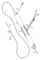
Fig. 1 is the intracavity speckle rotary rubbing device of a kind of eccentric cutting head embodiment that comprises inflexibility of the present invention and the perspective view of system;
Fig. 2 is the perspective view of taking apart of the flexible eccentric cutting head that formerly formed by driving shaft in the technology;
Fig. 3 be the eccentric cutting head that consisted of by driving shaft formerly technology take longitdinal cross-section diagram apart;
Fig. 4 be show the flexible off-centre that is consisted of by driving shaft in the technology formerly expand cutting head flexibility take longitdinal cross-section diagram apart;
Fig. 5 is formerly solid in the technology and be inflexibility, and the off-centre that is fixed in driving shaft is ground the longitdinal cross-section diagram of cone;
Fig. 6 be formerly have in the technology sharp keen near-end and remote edge grinding head take longitdinal cross-section diagram apart;
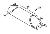
Fig. 7 is the perspective view of one embodiment of the invention;
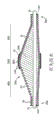
Fig. 8 is the side view of one embodiment of the invention;
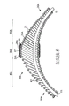
Fig. 9 is the upward view of one embodiment of the invention;
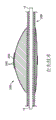
Figure 10 is the sectional view of taking apart of one embodiment of the invention;
Figure 11 is the longitdinal cross-section diagram of taking apart that shows the one embodiment of the invention geometric properties;
Figure 12 A-12C is the view in transverse section of the eccentric cutting head of one embodiment of the invention;
Figure 13 be the cutting head that shows one embodiment of the invention basically operative installations open narrow after, the longitdinal cross-section diagram in static (non-rotating) position;
Figure 14 is the view in transverse section that shows that the atwirl off-centre of the eccentric intracavity speckle rotary rubbing device of the present invention is expanded three diverse locations of cutting head;
Figure 15 shows is that as shown in figure 14 the atwirl off-centre of of the present invention eccentric intracavity speckle rotary rubbing device is expanded the schematic diagram of three diverse locations of cutting head;
Figure 16 is the side view of taking apart that the present invention is integrated with a flexible embodiment who stitches.
The specific embodiment
Because change or replacement that the present invention has various reasonable, therefore, this paper is by providing accompanying drawing and describing in detail to show details of the present invention.But, should be noted in the discussion above that its intention is not meant to limit invention and is specifically described embodiment.Opposite, it is intended that all changes of covering in design of the present invention and the scope, is equal to and replaces.
Fig. 1 has shown an embodiment of the disclosed intracavity speckle rotary rubbing device of commonly assigned U.S. Patent application (serial number 11/761128).This device comprises holds hand 10, and elongated, flexible driving shaft 20, driving shaft 20 have off-centre and expand grinding head 28 and the elongated conduit 13 that goes out from holding hand 10 remote extensions.As is known to the person skilled in the art, driving shaft 20 is made of the line of coiled coil, and grinding head 28 is fixed thereon.Further, the embodiment of the various driving shafts that the present invention is considered, as is known to the person skilled in the art, the coiling of the helical disk of driving shaft can contain few to 3 lines or 15 lines of as many as, may be that the right hand or left hand are crooked.Conduit 13 has the chamber, wherein accommodates most of length of driving shaft 20, except expanding grinding head 28 and the short parts of grinding head 28 far-ends that expand.Driving shaft 20 contains an inner chamber equally, so that driving shaft 20 can advance and rotation along wire 15.Liquid supply line 17 can be set so that Cooling and Lubricator liquid (being generally saline or another kind of biocompatible liquid) is introduced conduit 13.
Hold hand 10 and preferably comprise turbine (or similar rotary drive mechanism), with high speed rotating driving shaft 20.Hold hand 10 and generally can be connected to power source, such as the compressed air of carrying by pipe 16.Fibre-optic cable also can be set to 25 rotating speeds with monitoring turbine and driving shaft 20.With this details of holding hand and relevant apparatus be known in the art, and be described in the United States Patent (USP) 5314407 that for example licenses to Auth.Hold hand 10 and also preferably include control knob 11, with relative conduit 13 with hold the hand housing and advance and retraction turbine and driving shaft 20.
Fig. 2-4 has shown the details that the off-centre that comprises driving shaft 20A in the technology is formerly expanded the 28A of diameter grinding section.Driving shaft 20A comprises one or more helical buckling lines 18, defines guidewire lumen 19A and at the empty recessed 25A that expands among the grind section 28A.Except wire 15 passed empty recessed 25A, empty recessed 25A was empty basically.Relatively narrow position, off-centre are expanded the 28A of diameter grinding section and are comprised near-end 30A, middle part 35A and far-end 40A.Off-centre is expanded the diameter of coil 31 of near-end 30A of diameter portion 28A and is preferably progressively substantially increased to far-end with constant ratio, so roughly forms the shape of circular cone.The coil 41 of far-end 40A preferably has the diameter that substantially gradually reduces with constant speed, therefore the general cone shape that forms.Middle part 35 coil 36 is provided with stepping diameter, and so that the outer surface that is generally convex to be provided, outer surface is seamlessly transitted to provide between the near-end of eccentric diameter portion 28A and the distal end taper part expanding of driving shaft 20A by moulding.
Continue with reference to Fig. 2 of technology-4 formerly, the off-centre of driving shaft 28A is expanded at least part of (the preferred middle part 35A) of diameter grinding section and is comprised the outer surface that can remove tissue.Tissue is removed the grinding-material coating 24A that tissue that surface 37 comprises limiting driving shaft 20A is removed joint, and as shown in the figure, grinding-material coating 24A directly is attached on the coil of driving shaft 20A by suitable binding agent 26A.
Fig. 4 has shown that the off-centre of the driving shaft 28A of technology formerly expands the flexibility of diameter grinding section, has shown the driving shaft 20A that advances along wire 15.Show in an embodiment, the adjacent windings that the off-centre of driving shaft is expanded on the middle part 35A of diameter grinding section is together fixed to one another, by binding agent 26A is bonding abrasive grains 24A is fixed on the coil 36.The off-centre of driving shaft is expanded close end 30A and the distal portion 40A of diameter portion and is made of coil 31 and 41 respectively, and coil is fixing each other, like this so that these parts of driving shaft can bending, as shown in the figure.This flexibility has promoted the propelling of device by relative zigzag channel the time, and at some embodiment, off-centre is expanded the 28A of diameter grinding section rotoflector in high speed rotating.As an alternative, the off-centre of driving shaft is expanded the adjacent windings 36 of the 28A of diameter grinding section middle part 35A can be fixed to one another, limits the flexibility of grind section 28A with this.
Fig. 5 has shown the another kind of formerly intracavity speckle rotary rubbing device of technology, and device comprises the asymmetric solid grinding cone 28B that is fixed in flexible drive shaft 20B, and the wire 15 that provides along the US Patent No. 5681336 such as Clement rotates.Driving shaft 20B can be flexible, and still, asymmetric solid grinding cone 28B is inflexibility.The part outer surface that eccentric tissue is removed cone 28B is fixed with abrasive grains layer 24B by suitable binding agent 26B.The purposes of this structure is limited, but because capable illustrated at the 3rd hurdle 53-55 such as Clement, asymmetrical cone rotates with " than the low speed of high speed rotating grinding device ", " to offset heat and unbalance ".That is to say, for the two solid-cone of intended size and quality, can not be with the high speed of when intracavity speckle turnery operates, using, such as rotating cone in the range of speeds of 20000-200000 rpm.What is more important, departing from of the turning cylinder barycenter of driving shaft will cause significantly, and be the formation of unwanted centrifugal force, arterial wall be produced excessive pressure, and produce too much heat and excessive granule.
Fig. 6 has shown that the off-centre that is disclosed in the commonly assigned U.S. Patent application (serial number 11/761128) expands another embodiment of grinding head 28C.At this embodiment, as shown in the figure, driving shaft 20 in grinding head 28C, has a breach with the partial fixing of two separation therebetween, and eccentric grinding head 28 is fixed in two parts of driving shaft.As an alternative, driving shaft 20 can be unitary construction.Illustrated close end 30 and distal portion 40 are isometric basically, are provided with middle part 35 therebetween.Illustrated close end front is substantially perpendicular to driving shaft 20 along 30A and distal portion front along 40A, has therefore formed hard and sharp keen limit E.In the high speed rotating process, this hard also sharp keen limit can cause the damage of tube wall, and this is a kind of result who does not expect very much.
Forward now Fig. 7-11 to, will discuss the inflexibility of intracavity speckle rotary rubbing device of the present invention, off-centre is expanded an embodiment of grinding head 28.Grinding head 28 can comprise tissue removing surface 37 that at least one is positioned at middle part 35, distal portion 40 and/or close end 30 outer surfaces, to promote narrow wearing and tearing in the high speed rotating process.Tissue is removed surface 37 can comprise the grinding-material layer 24 that is combined in grinding head 28 middle parts 35, distal portion 40 and/or close end 30.Grinding-material can be any suitable material, such as diamond dust, vitreous silica, titanium nitride, tungsten carbide, aluminium oxide, Norbide., or other ceramic materials.Preferred grinding-material is made of the coil that directly is fixed on driving shaft 20 by suitable binding agent diamond chip (or diamond dust granule), this fixing technology that can know by use realizes such as traditional plating or fusion technique (referring to US Patent No. 4018576).As an alternative, outer tissue is removed the surface can be by machinery or chemical roughening middle part 35, and the outer surface of distal portion 40 and/or close end 30 consists of, and removes surface 37 to provide suitable tissue to grind.The another kind of replacement, outer surface by etching or cutting (as, pass through laser), so that a kind of little but effective abradant surface to be provided.Other similar technology also can be used for providing a suitable tissue to remove surface 37.
Preferred plan as shown in Figures 9 and 10, the chamber of at least part of sealing or stitch 23 and can be set to vertically to pass along the turning cylinder 21 of driving shaft 20 and expand grinding head 28 is to be fixed to driving shaft 20 with grinding head 28 by technology well-known to those skilled in the art.In various embodiments, the quality (and barycenter with respect to position of the turning cylinder 21 of driving shaft) of cavity 25 to reduce and to control grinding head 28 can be set, being beneficial to anti-damage grinds, and improve grinding head 28 at a high speed, such as the predictability of TRAJECTORY CONTROL in the operating process of 20000 to 200000 rpm.As the skilled person will recognize, orbit amplitude can operate predictedly, and its basis is that barycenter is with respect to the position of the turning cylinder of driving shaft.Therefore, with less cavity 25(or do not have cavity 25) compare, the existence of larger cavity 25 will make barycenter move more near turning cylinder 21, under given rotating speed, will cause the diameter that less orbit amplitude and/or grinding head 28 produce in the high speed rotating process.
Each width of cloth among Fig. 7-11 has all shown proximal edge and the remote edge P of rounding
R, D
RProximal edge and remote edge P
R, D
RCircular essence be conducive to progress into narrow, meanwhile minimize the common damage to tube wall.Can recognize easily proximal edge and remote edge P such as those skilled in the art
R, D
RMay have multiple radius, all these radiuses all are within the scope of the present invention.Embodiment shown in the figure comprises the rounded edges with equal radii, but proximal edge and remote edge P
R, D
RAlso can comprise radius unequal.In addition, at other embodiment, grinding head can contain the near-end rounded edges and distal surface is not rounding.Further, remote edge can be rounding and proximal end face is not.
In illustrated embodiment, grinding head 28 can be fixed on the driving shaft 20, and wherein driving shaft is by a cell formation.As an alternative, will discuss as following, driving shaft 20 can be made of the sheet of two separation, and the eccentric grinding head 28 that wherein expands is fixed on two sheets of driving shaft 20, and a breach is arranged therebetween.The constructing technology of this two driving shafts can combine with cavity 25, further controls the location of grinding head 28 barycenter.Can revise the size and dimension of cavity 25 to optimize the track rotate path of grinding head 28, special rotating speed for needs.Those skilled in the art will recognize various possible structures easily, and wherein each within the scope of the present invention.
Embodiment shown in Fig. 7-11, close end 30 and distal portion 40 have symmetrical shape and length.Other embodiment can prolong the length of close end 30 or distal portion 40, to obtain asymmetric vertical outward appearance.
Especially with reference to Figure 11, driving shaft 20 has the turning cylinder 21 coaxial with wire 15, and wire 15 is positioned at the chamber 19 of driving shaft 20.Therefore, off-centre is expanded outer surface that the close end 30 of grinding head 28 has and is substantially limited by the outer surface of the frustum of a cone and form, and cone has the axle 32 that the turning cylinder 21 with relative low-angle β and driving shaft 20 intersects.Similarly, the outer surface that the distal portion 40 of grinding head 28 of expanding has is substantially limited by the outer surface of the frustum of a cone and forms, and cone has the axle 42 that the turning cylinder 21 with relative low-angle β and driving shaft 20 intersects.The cone axis 32 of close end 30 and the cone axis 42 of distal portion 40 intersect each other, and be coplanar with vertical turning cylinder 21 of driving shaft.
The opposite of cone generally respectively should approximately 10 ° to the about angle α between 30 °; Preferred angle α approximately 20 ° to approximately between 24 °, optimum angle α is approximately 22 °.Same, the cone axis 32 of close end 30 and the cone axis of distal portion 40 42 generally approximately 20 ° to approximately the angle β between 8 ° is crossing with the turning cylinder 21 of driving shaft 20.Preferred angle β approximately 3 ° to approximately between 6 °.Although in the illustrated preferred embodiment, the angle α of the distal portion of grinding head 28 and close end of expanding generally equates, they needn't be identical.This diagonal angle β also is the same.
In alternative embodiment, middle part 35 can comprise the diameter that progressively increases to the intersection of close end 30 from the intersection of distal portion 40.At this embodiment, angle α, comparable large in distal portion 40 at close end 30 as shown in Figure 6, or opposite.Further alternative embodiment comprises the middle part 35 with convex surface, and wherein the middle part outer surface can be moulded to provide between the close end outer surface of close end and distal portion and distal portion outer surface and seamlessly transit.
Because cone axis 32 and 42 turning cylinders 21 with angle β and driving shaft 20 intersect, off-centre is expanded the barycenter of grinding head 28 so radiation profiles around vertical turning cylinder 21 of driving shaft 20.Following will describe in detail, the rotating shaft 21 that barycenter departs from driving shaft makes and expands grinding head 28 and have certain eccentricity, allow it to open tremulous pulse to basically larger diameter, expand the nominal diameter of grinding head 28 greater than off-centre, preferably, the diameter of opening is at least the twice that off-centre is expanded grinding head 28 nominal diameters.
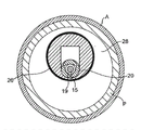
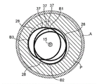
Figure 12 A-12C has described the off-centre shown in Fig. 7-11 and has expanded 3 cross section thin slices (being shown as lateral cross section) of barycenter 29 of grinding head 28, off-centre is expanded grinding head 28 and is fixed on the driving shaft 20, driving shaft 20 advances along wire 15, and wire 15 is driving within the axocoel 19.Whole off-centre is expanded grinding head 28 and can be divided into many such thin slices, and each thin slice has its barycenter.Figure 12 B chooses is that off-centre is expanded grinding head 28 and had the position of its maximum cross-section diameter (in this embodiment, it is that off-centre is expanded the maximum gauge at grinding head 28 middle parts 35), Figure 12 A and 12C are respectively the cross sections of far-end 40 and near-end 30 that off-centre is expanded grinding head 28.In every a slice of these cross section thin slices, barycenter 29 distributes away from the turning cylinder 21 of driving shaft 20, and the turning cylinder of driving shaft 20 is consistent with wire 15.The barycenter 29 of each cross section thin slice generally also overlaps with the geometric center of this cross section thin slice.Figure 12 B has shown the cross section thin slice at middle part 35, comprises the maximum cross-section diameter of grinding head 28, compares with distal portion 40 with close end 30, and its barycenter 29 and geometric center both are positioned at turning cylinder 21 places away from (being largest interval) driving shaft 20.
Will be appreciated that, at this paper, term " off-centre " is defined as and be used for describes and expands the position difference of geometric center between the turning cylinder 21 of grinding head 28 and driving shaft 20, or the position difference of expanding barycenter 29 between the turning cylinder 21 of grinding head 28 and driving shaft 20.The difference that any one is such is under suitable rotating speed, with so that the eccentric grinding head 28 that expands is opened narrow in basically expanding the diameter of grinding head 28 nominal diameters greater than off-centre.In addition, off-centre with random geometry is expanded grinding head 28, its " geometric center " roughly can be by the mid point of location picture through the long-chord of the turning cylinder 21 of driving shaft, and connect its off-centre expand 2 that the periphery of grinding head 28 has on the cross section of greatest length place determine.
The grinding head 28 of intracavity speckle rotary rubbing device of the present invention can be made by rustless steel, tungsten or similar material.Grinding head 28 can be made of single integrated piece, or as an alternative, is fixed together to realize purpose of the present invention by two or more assemblnig grinding head parts.
Person of skill in the art will appreciate that in this illustrated embodiment, comprise at least one aforesaid tissue removing surface 37.This tissue is removed on one or more in middle part 35, close end 30 and/or the distal portion 40 that surface 37 can be arranged on eccentric grinding head 28.Near-end and/or far-end rounded edges P
R, D
RAlso can be provided with tissue and remove the surface, be distributed with aforesaid grinding-material on it.
In some cases, comprise the sort of situation discussed herein, grinding head 28 can be used for opening little by little and with no damage an opening, use distal portion 40 diameters that grinding head 28 increases gradually with the diameter of enlarged openings until enough specklees are eliminated, allow grinding head 28 propellings to penetrate narrow, then recall within it.The ability of opening pilot hole strengthens by several features.Cone shape close end 30 is removed surface 37 to narrow grinding path so that can advance gradually and control tissue, obtains to be used for continuing to advance the pilot hole of grinding head 28.Near-end and/or the remote edge P of circular chamfering
R, D
RFurther promote the generation of pilot hole, and so described, and its surface is provided with grinding-material and opens pilot hole to help also not damaged gradually.Further, coniform close end 30(and the distal portion 40-of grinding head 28 do not show in the drawings) can limit the edge with the junction at cylindric middle part 35, this edge can cut or grind speckle when the device iterative method, and then expansion is polished narrow diameter.In addition, as mentioned above, the close end 30 of grinding head 28, and middle part 35 and distal portion 40(do not show in the drawings) the surface, can cover wholly or in part tissue and remove the grinding-material on surface 37, and then by narrow propelling with recall the grinding that promotes speckle and open narrow in progressive and controlled mode.At last, sufficiently speckle will be eliminated, so that whole grinding head 28 can penetrate narrow propelling and recall.
In addition, the size of the grinding head 28 of inflexibility can suitably design to produce passes narrow pilot hole, essential produce be used for lasting increase grinding head 28 of the present invention along passage, opening is opened gradually like this, maybe may create pilot hole so that some formerly, such as the device of describing in Shturman 6494890, namely the flexible off-centre of the driving shaft section of expanding can enter subsequently.A kind of like this arrange can comprise the device that uses two separation or in conjunction with two (or more) in a device.Perhaps, for example, along driving shaft 20 far-ends the eccentric grinding head 28 of inflexibility of the present invention being set, in conjunction with near-end setting more, is favourable as expand grind section in the flexible off-centre of Shturman 6494890 disclosed driving shafts 20.In this embodiment, pilot hole can use the grinding head 28 of inflexibility to open, and the flexible off-centre of driving shaft 20 is expanded grind section and can be followed and pass narrowly like this, further opens it.As an alternative, the inflexibility grinding head 28 that continue to increase can be arranged along driving shaft 20 continuously, and the minimum end that is positioned at away from driving shaft 20 is namely near narrow.Further replace, inflexibility and flexible (discussing hereinafter), the combination of eccentric grinding head 28 can arrange continuously along driving shaft 20.
Figure 13 has shown that off-centre that the present invention has a wire 20 expands grinding head 28, the grinding head 28 that adheres to advances along wire 15, and narrow basically opened after, be in " rest position " in the tremulous pulse " A ", therefore, shown that device can open narrow in the diameter that surpasses the device nominal diameter far away.
The narrow diameter that is opened to expands the degree of grinding head nominal diameter greater than off-centre of the present invention and depends on several parameters in the tremulous pulse, comprise off-centre expand shape, the off-centre of grinding head expand grinding head quality, quality distribution and, therefore, the interior barycenter of grinding head is with respect to the position of the turning cylinder of driving shaft, and rotating speed.
Rotating speed is a key factor when determining centrifugal force, and centrifugal force is the surperficial power of oppressing stenotic tissue of tissue removing of expanding grinding head, and then organizes clearance rate so that the operator can control.The control of rotating speed equally also can, to a certain extent, control device will be opened narrow maximum gauge.The applicant also finds to control reliably tissue and removes the ability of the power of surface compressing stenotic tissue and the operator is controlled better organize clearance rate, can also control better the size that is eliminated granule.
Figure 14-15 has shown the roughly helical orbit by the various embodiment uses of the eccentric grinding head 28 of the present invention, and grinding head 28 demonstrations are with respect to wire 15, and grinding head 28 is along its propelling.For illustration purposes, the height of the helical-like path among Figure 14-15 has been exaggerated, in fact, off-centre is expanded each helical-like path of grinding head 28 and is removed 37 removings in a surface layer tissue as thin as a wafer by tissue, when the device forward with oppositely by narrow when repeatedly moving, expanding the effect of grinding head 28 by off-centre, to have produced many, many such spirals narrow to get through up hill and dale.Figure 14 has shown 3 different rotary positions that the off-centre of intracavity speckle rotary rubbing device of the present invention is expanded grinding head 28.In each position, expand the contacted speckle of abradant surface " P " of grinding head 28 from off-centre and be removed--these 3 positions are distinguished by 3 different points that contact with speckle " P ", and these points are denoted as B1, B2 and B3 in the drawings.Note, at each point, it generally is that off-centre is expanded the same section of abradant surface of grinding head 28 and removed surperficial 37 with radiation as far as possible away from the tissue of the turning cylinder of driving shaft and contact.
Except the embodiment of above-mentioned inflexibility grinding head, various embodiments of the present invention further comprises partially flexible at eccentric grinding head 28.Typical embodiment is shown among Figure 15-18.
Figure 15 has shown the grinding head that provides in Fig. 7-11 has been provided, but has been provided with flexible seam 46 at grinding head 28.Illustrated seam 46 is for cutting grinding head 28 fully and entering chamber 23, so that grinding head 28 can be farthest crooked.But, person of skill in the art will appreciate that seam 46 needn't extend to chamber 23, and can be by nicking grinding head 28 effectively but not extend into chamber 23 to obtain its flexibility.Among the embodiment, grinding head 28 will be with flexible drive shaft 20 bendings, with the propelling of facilitation in the target cavity of many curved pathway in each.This flexibility of grinding head 28 also can provide still less damaging withdrawing from so that provide still less damaging entering in entering the process that pathological changes grinds.At least need a flexibility seam 46 so that this flexibility to be provided; A plurality of flexible seams 46 preferably are set.
The embodiment of the flexible grinding head 28 of Figure 15 has shown a series of flexibilities seams that are evenly distributed 46, and width and the degree of depth of flexible seam 46 are substantially equal, its centre joint 46 by complete nicking by grinding head 28 and arrive chamber 23 in it.The flexibility that person of skill in the art will appreciate that grinding head 28 can be controlled, and for example passes through, and modifies, handles by artificial, particularly one or more with lower member: the quantity of seam 46; The degree of depth of seam 46 in grinding head 28; The width of seam 46; The cutting angle of seam 46; The distribution of seam 46 on grinding head 28.
Therefore, the flexible characteristic of grinding head can stitch 46 with flexibility and controls or modify.Some embodiment of the present invention can comprise, for example, flexible seam 46 concentrates near grinding head 28 centers, namely is distributed in the middle part 35, only has a seam 46 to be positioned at 30, one seams 46 of close end and is positioned at distal portion 40.To those skilled in the art, obviously have many kinds possible be equal to replacement; Each within the scope of the present invention.
As mentioned above, the embodiment of each flexible grinding head can comprise grinding-material disposed thereon, and combines with inflexibility embodiment.
Therefore eccentric grinding head 28 of the present invention can comprise embodiment inflexibility and/or at least part of flexibility.
Although do not wish to be defined in any specific operation principle, the applicant believes that barycenter departs from rotating shaft and caused " track " motion of expanding grinding head, and the diameter of " track " can be by changing, and particularly the rotating speed of driving shaft is controlled.No matter the geometrical rule of " track " motion as whether shown in Figure 14-15 determined, but applicant's experience show by changing the rotating speed of driving shaft, can control and promote the eccentric tissue that expands grinding head 28 to remove the centrifugal force on the narrow surface of antagonism, surface.Centrifugal force can be according to formula:
Fc=m Δ x (π n/30) 2 Determine.
Wherein, Fc is centrifugal force, and m is the quality that off-centre is expanded grinding head, and Δ x is that off-centre is expanded distance between the turning cylinder of grinding head barycenter and driving shaft, and n is the revolution (rpm) of per minute.The control of this power Fc provides being eliminated the control of Tissue velocity, the control that will open narrow maximum gauge to device, and to being eliminated the improvement control of tissue particles size.
Compare with high speed intracavity speckle rotary rubbing device formerly, grinding head 28 of the present invention has larger quality.Therefore, can obtain larger track in the high speed rotating process, this is conversely so that can use than formerly installing little grinding head.Except producing the pilot hole at the tremulous pulse that fully or basically stops up etc., in the process of inserting, use less grinding head will obtain larger path convenience and damage still less.
During operation, use intracavity speckle rotary rubbing device of the present invention, off-centre is expanded grinding head 28 and is is repeatedly come and gone by narrow.By the rotating speed of modifier, can control tissue and remove the surface to the power of stenotic tissue, and then control better the speed of speckle removal and the granular size that is eliminated tissue.Because narrow being opened to greater than off-centre expanded the larger diameter of grinding head 28 nominal diameters, liquid coolant and blood can be constantly flow around expanding grinding head.In case grinding head passes pathological changes, this lasting the flowing of blood and liquid coolant constantly washed away the tissue particles that is eliminated, and then the consistent release that is eliminated granule is provided.
Off-centre expand maximum cross-section section diameter that grinding head 28 has at about 1.0 mm to approximately between 3.0 mm.Therefore, off-centre is expanded the diameter of section that grinding head has and is included, but are not limited to: 1.0 mm, 1.25 mm, 1.50mm, 1.75 mm, 2.0 mm, 2.25 mm, 2.50 mm, 2.75 mm and 3.0 mm.Person of skill in the art will appreciate that, the above-mentioned diameter of section that increases progressively take 0.25mm as gradient only is typical, and the present invention is not limited to described exemplary list, and therefore, the diameter of section that increases progressively with other gradients also is possible and within the scope of the present invention.
As mentioned above, because the eccentricity of grinding head 28 of expanding depends on a plurality of parameters, the applicant find that following design parameter can be considered to and the turning cylinder 21 of driving shaft 20 and transversal facial geometric center between distance dependent, expand the diameter place, maximum cross-section of grinding head in off-centre and get a position: the maximum cross-section diameter is expanded the device of grinding head at about 1.0 mm to the about off-centre between 1.5 mm, geometric center is preferably to distribute at least about the distance of the 0.02mm turning cylinder from driving shaft, and is preferred with the distance at least about 0.035 mm; The maximum cross-section diameter is expanded the device of grinding head at about 1.5 mm to the about off-centre between 1.75 mm, geometric center is preferably to distribute at least about the distance of the 0.05 mm turning cylinder from driving shaft, preferred with the distance at least about 0.07mm, best with the distance at least about 0.09 mm; The maximum cross-section diameter is expanded the device of grinding head at about 1.75 mm to the about off-centre between 2.0 mm, geometric center is preferably to distribute at least about the distance of the 0.1 mm turning cylinder from driving shaft, preferred with the distance at least about 0.15 mm, best with the distance at least about 0.2 mm; And the off-centre of maximum cross-section diameter more than 2.0 mm expanded the device of grinding head, geometric center is preferably to distribute at least about the distance of the 0.15 mm turning cylinder from driving shaft, preferred with the distance at least about 0.25 mm, best with the distance at least about 0.3 mm.
Design parameter equally can be based on the position of barycenter.The maximum cross-section diameter is expanded the device of grinding head 28 at about 1.0 mm to the about off-centre between 1.5 mm, and barycenter is preferably to distribute at least about the distance of the 0.013 mm turning cylinder from driving shaft, preferably with the distance at least about 0.02 mm; The maximum cross-section diameter is expanded the device of grinding head 28 at about 1.5 mm to the about off-centre between 1.75 mm, and barycenter is preferably to distribute at least about the distance of the 0.03 mm turning cylinder from driving shaft, preferably with the distance at least about 0.05mm; The maximum cross-section diameter is expanded the device of grinding head 28 at about 1.75mm to the about off-centre between the 2.0mm, and barycenter is preferably to distribute at least about the distance of the 0.06 mm turning cylinder from driving shaft, preferably with the distance at least about 0.1mm; And the maximum cross-section diameter expanded the device of grinding head 28 in the about off-centre more than 2.0 mm, barycenter is preferably to distribute at least about the distance of the 0.1 mm turning cylinder from driving shaft, preferably with the distance at least about 0.16 mm.
Preferably, the thickness of wall 50, for example, shown in Figure 10 C, the outer surface that cavity and near-end 30, middle part 35 and/or far-end 40 are limited is separated should be at least 0.008 inch, to guarantee stability and the integrity of structure.
Preferably, the design parameter of selecting makes and expands enough off-centre of grinding head 28, when fully strain to get rid of any potential movement of wire along fixing cord 15() with greater than the rotating speed rotation of about 20000 rpm the time, its at least a portion tissue is removed rotatable path (no matter this path whether be preferably rule or annular) of expanding grinding head 28 nominal diameters greater than off-centre by diameter, surface 37.For example, be not to limit, for maximum gauge at about 1.5 mm to approximately expanding grinding head 28 between 1.75 mm, tissue is removed at least a portion on surface 37 and can be rotated by diameter than eccentric path of expanding grinding head 28 nominal diameters about at least 10%, preferably expand grinding head 28 nominal diameters than off-centre about at least 15%, bestly expand grinding head 28 nominal diameters about at least 20% than off-centre.For maximum gauge at about 1.75 mm to approximately expanding grinding head 28 between 2.0 mm, organize at least a portion of removing section can rotate by diameter than eccentric path of expanding grinding head 28 nominal diameters about at least 20%, preferably expand grinding head 28 nominal diameters than off-centre about at least 25%, bestly expand grinding head 28 nominal diameters about at least 30% than off-centre.Expand grinding head 28 to what maximum gauge was at least about 2.0 mm, tissue is removed the rotatable path by diameter of at least a portion on surface 37, preferably expands grinding head 28 nominal diameters about at least 40% than off-centre.
Preferably, the design parameter of selecting can make and expand enough off-centre of grinding head 28, when along defending tenaciously wire 15 with about 20000 rpm during to the about rotation of the speed between 200000 rpm, the path (no matter this path whether be preferably rule or annular) that at least a portion rotation that its tissue is removed surface 37 is expanded grinding head 28 maximum nominal diameters greater than off-centre substantially by maximum gauge.In certain embodiments, the present invention can limit maximum gauge increases approximately 50% to the about track between 400% than the eccentric maximum nominal diameter that expands grinding head 28.The maximum gauge of preferred this track than the eccentric maximum nominal diameter about 200% that expands grinding head 28 to approximately 400%.
The present invention should not be regarded as being limited to above-mentioned specific examples, and is appreciated that covering all aspects of the present invention.Various modifications, equivalent steps, and after the direct understanding of those skilled in the art according to this description, that makes apparently is applicable to various structures of the present invention.
Claims (39)
1. one kind is used for getting through narrow intracavity speckle rotary rubbing device at the intra-arterial with given diameter, comprising:
Maximum gauge is less than the wire of artery diameter;
Flexible, elongated, as can to advance along wire rotatable drive shaft, driving shaft has turning cylinder; And at least one eccentric grinding head, described at least one eccentric grinding head comprises the single integrated piece structure of the inflexibility that is fixed in driving shaft, and comprise the barycenter of the turning cylinder location of radially departing from driving shaft, eccentric grinding head comprises close end, middle part and distal portion, wherein close end comprises the near-end outer surface, the middle part comprises the middle part outer surface, distal portion comprises distal outer surface, the near-end outer surface has diameter and the rounded proximal ends rounded edges that enlarges to far-end, described rounded proximal ends rounded edges comprises Radius, distal outer surface has diameter and the rounded distal rounded edges of dwindling to far-end, described rounded distal rounded edges comprises Radius, wherein the radius of the radius of rounded proximal ends rounded edges and rounded distal rounded edges is substantially equal, the middle part outer surface is cylindric, wherein the middle part outer surface comprises the removing section that organizes at least, define penetrating driving axocoel and cavity in the eccentric grinding head, described cavity has size and dimension, thereby the small part that is positioned to of the barycenter of at least one eccentric grinding head determines, and at least part of driving axocoel that passes of driving shaft wherein;
Wherein said at least one eccentric grinding head comprise a static diameter and in the high speed rotating process traversal one orbital path, the result of wherein said at least one eccentric grinding head off-centre is that orbital path by described at least one eccentric grinding head traversal is greater than static diameter.
2. intracavity speckle rotary rubbing device according to claim 1, wherein drive shaft section is passed and is driven axocoel and single, the complete driving shaft of formation attached to it.
3. intracavity speckle rotary rubbing device according to claim 1, wherein drive shaft section is passed and is driven axocoel and attached to it, comprises at least two parts, and every part all is attached to the driving axocoel, between described at least two parts driving shaft a breach is arranged.
4. intracavity speckle rotary rubbing device according to claim 1, wherein the near-end outer surface of at least one eccentric grinding head roughly is defined as the outer surface of cone, and cone has the axle that the turning cylinder with driving shaft intersects.
5. intracavity speckle rotary rubbing device according to claim 1, wherein the distal outer surface of at least one eccentric grinding head roughly is defined as the outer surface of cone, and cone has the axle that the turning cylinder with driving shaft intersects.
6. intracavity speckle rotary rubbing device according to claim 1, wherein the rounded proximal ends rounded edges comprises that tissue removes the surface.
7. intracavity speckle rotary rubbing device according to claim 1, wherein the rounded distal rounded edges comprises that tissue removes the surface.
8. intracavity speckle rotary rubbing device according to claim 1, wherein near-end, far-end and middle part outer surface comprise the removing section that organizes.
9. intracavity speckle rotary rubbing device according to claim 1, wherein only the middle part outer surface comprises the removing section that organizes.
10. intracavity speckle rotary rubbing device according to claim 4, wherein the cone axis of the cone axis of near-end outer surface and distal outer surface intersects each other and is coplanar with the turning cylinder of driving shaft.
11. intracavity speckle rotary rubbing device according to claim 1, wherein distal outer surface has the diameter that enlarges to far-end with constant ratio, and then roughly forms cone shape.
12. intracavity speckle rotary rubbing device according to claim 11, wherein the near-end outer surface has the diameter that dwindles to far-end with constant ratio, and then roughly forms cone shape.
13. intracavity speckle rotary rubbing device according to claim 12, there is 10 ° to 30 ° angle α to each other in the face that wherein each cone is relative.
14. intracavity speckle rotary rubbing device according to claim 12, there is 20 ° to 24 ° angle α to each other in the face that wherein each cone is relative.
15. intracavity speckle rotary rubbing device according to claim 12, wherein each cone of at least one eccentric grinding head has not parallel with the turning cylinder of driving shaft axle.
16. intracavity speckle rotary rubbing device according to claim 12, wherein the cone axis of the close end of at least one eccentric grinding head and distal portion is coplanar, and intersects with the turning cylinder of the angle β between 2 ° to 8 ° and driving shaft respectively.
17. intracavity speckle rotary rubbing device according to claim 12, wherein the cone axis of the close end of at least one eccentric grinding head and distal portion is coplanar, and intersects with the turning cylinder of the angle β between 3 ° to 6 ° and driving shaft respectively.
18. intracavity speckle rotary rubbing device according to claim 1, wherein the middle part outer surface is used for providing the shape that seamlessly transits between the near-end of eccentric grinding head and distal outer surface.
19. intracavity speckle rotary rubbing device according to claim 1, wherein the near-end of at least one eccentric grinding head and distal outer surface roughly are symmetrical to each other.
20. intracavity speckle rotary rubbing device according to claim 1, wherein between the 1.5mm, barycenter distributes with the distance of the 0.013mm turning cylinder from driving shaft the eccentric maximum gauge that expands diameter portion at least at 1.0mm.
21. intracavity speckle rotary rubbing device according to claim 1, wherein between the 1.75mm, barycenter distributes with the distance of the 0.03mm turning cylinder from driving shaft the eccentric maximum gauge that expands diameter portion at least at 1.5mm.
22. intracavity speckle rotary rubbing device according to claim 1, wherein between the 2.0mm, barycenter distributes with the distance of the 0.06mm turning cylinder from driving shaft the eccentric maximum gauge that expands diameter portion at least at 1.75mm.
23. intracavity speckle rotary rubbing device according to claim 1, wherein the eccentric maximum gauge that expands diameter portion is 2.0mm at least, and barycenter is at least with the turning cylinder distribution from driving shaft of the distance of 0.1mm.
24. intracavity speckle rotary rubbing device according to claim 1, wherein between the 1.5mm, barycenter distributes with the distance of the 0.02mm turning cylinder from driving shaft the eccentric maximum gauge that expands diameter portion at least at 1.0mm.
25. intracavity speckle rotary rubbing device according to claim 1, wherein between the 1.75mm, barycenter distributes with the distance of the 0.05mm turning cylinder from driving shaft the eccentric maximum gauge that expands diameter portion at least at 1.5mm.
26. intracavity speckle rotary rubbing device according to claim 1, wherein between the 2.0mm, barycenter distributes with the distance of the 0.1mm turning cylinder from driving shaft the eccentric maximum gauge that expands diameter portion at least at 1.75mm.
27. intracavity speckle rotary rubbing device according to claim 1, wherein the eccentric maximum gauge that expands diameter portion is 2.0mm at least, and barycenter is at least with the turning cylinder distribution from driving shaft of the distance of 0.16mm.
28. intracavity speckle rotary rubbing device according to claim 1 wherein is positioned at off-centre and expands the off-centre at diameter place, diameter portion maximum cross-section and expand the cross section of diameter portion and have the geometric center that the turning cylinder away from driving shaft distributes.
29. intracavity speckle rotary rubbing device according to claim 28, wherein between the 1.75mm, geometric center distributes with the distance of the 0.05mm turning cylinder from driving shaft the eccentric maximum cross-section diameter that expands diameter portion at least at 1.5mm.
30. intracavity speckle rotary rubbing device according to claim 28, wherein between the 2.0mm, geometric center distributes with the distance of the 0.1mm turning cylinder from driving shaft the eccentric maximum cross-section diameter that expands diameter portion at least at 1.75mm.
31. intracavity speckle rotary rubbing device according to claim 28, the eccentric maximum cross-section diameter that expands diameter portion 2.0mm at least wherein, geometric center distributes with the distance of the 0.15mm turning cylinder from driving shaft at least.
32. intracavity speckle rotary rubbing device according to claim 28, wherein between the 1.5mm, geometric center distributes with the distance of the 0.035mm turning cylinder from driving shaft the eccentric maximum cross-section diameter that expands diameter portion at least at 1.0mm.
33. intracavity speckle rotary rubbing device according to claim 28, wherein between the 1.75mm, geometric center distributes with the distance of the 0.07mm turning cylinder from driving shaft the eccentric maximum cross-section diameter that expands diameter portion at least at 1.5mm.
34. intracavity speckle rotary rubbing device according to claim 28, wherein between the 2.0mm, geometric center distributes with the distance of the 0.15mm turning cylinder from driving shaft the eccentric maximum cross-section diameter that expands diameter portion at least at 1.75mm.
35. intracavity speckle rotary rubbing device according to claim 28, the eccentric maximum cross-section diameter that expands diameter portion 2.0mm at least wherein, geometric center distributes with the distance of the 0.25mm turning cylinder from driving shaft at least.
36. intracavity speckle rotary rubbing device according to claim 28, wherein between the 1.75mm, geometric center distributes with the distance of the 0.09mm turning cylinder from driving shaft the eccentric maximum cross-section diameter that expands diameter portion at least at 1.5mm.
37. intracavity speckle rotary rubbing device according to claim 28, wherein between the 2.0mm, geometric center distributes with the distance of the 0.20mm turning cylinder from driving shaft the eccentric maximum cross-section diameter that expands diameter portion at least at 1.75mm.
38. intracavity speckle rotary rubbing device according to claim 28, wherein the eccentric maximum cross-section diameter that expands diameter portion is at least 2.0mm, and geometric center distributes with the distance of the 0.30mm turning cylinder from driving shaft at least.
39. intracavity speckle rotary rubbing device according to claim 1, wherein organizing removing section is abradant surface.
Applications Claiming Priority (3)
| Application Number | Priority Date | Filing Date | Title |
|---|---|---|---|
| US12/130,024 US8758377B2 (en) | 2008-05-30 | 2008-05-30 | Eccentric abrading and cutting head for high-speed rotational atherectomy devices |
| US12/130,024 | 2008-05-30 | ||
| PCT/US2009/043451 WO2009146248A1 (en) | 2008-05-30 | 2009-05-11 | Eccentric abrading and cutting head for high-speed rotational atherectomy devices |
Publications (2)
| Publication Number | Publication Date |
|---|---|
| CN102046100A CN102046100A (en) | 2011-05-04 |
| CN102046100B true CN102046100B (en) | 2013-04-24 |
Family
ID=41377525
Family Applications (1)
| Application Number | Title | Priority Date | Filing Date |
|---|---|---|---|
| CN200980119846.4A Active CN102046100B (en) | 2008-05-30 | 2009-05-11 | Eccentric abrading and cutting head for high-speed rotational atherectomy devices |
Country Status (9)
| Country | Link |
|---|---|
| US (1) | US8758377B2 (en) |
| EP (1) | EP2303149B1 (en) |
| JP (1) | JP5653347B2 (en) |
| CN (1) | CN102046100B (en) |
| AU (1) | AU2009251467B2 (en) |
| CA (1) | CA2718074C (en) |
| DK (1) | DK2303149T3 (en) |
| NO (1) | NO2303149T3 (en) |
| WO (1) | WO2009146248A1 (en) |
Families Citing this family (23)
| Publication number | Priority date | Publication date | Assignee | Title |
|---|---|---|---|---|
| US8551130B2 (en) * | 2010-02-18 | 2013-10-08 | Cardiovascular Systems, Inc. | Therapeutic agent delivery system, device and method for localized application of therapeutic substances to a biological conduit |
| US9907567B2 (en) * | 2010-05-04 | 2018-03-06 | Samuel Shiber | Mechanical — pharmaceutical system for opening obstructed bodily vessels |
| US9289230B2 (en) * | 2012-09-17 | 2016-03-22 | Cardiovascular Systems, Inc. | Rotational atherectomy device with a system of eccentric abrading heads |
| US20150005791A1 (en) * | 2013-06-28 | 2015-01-01 | Cardiovascular Systems, Inc. | Atherectomy device having combined open/close drive shaft |
| US20150080795A1 (en) | 2013-07-26 | 2015-03-19 | Cardiovascular Systems, Inc. | Devices, systems and methods for performing atherectomy and subsequent balloon angioplasty without exchanging devices |
| US10271869B2 (en) | 2014-03-01 | 2019-04-30 | Rex Medical, L.P. | Atherectomy device |
| WO2015138247A1 (en) | 2014-03-12 | 2015-09-17 | Boston Scientific Limited | Infusion lubricated atherectomy catheter |
| US10405878B2 (en) | 2014-07-25 | 2019-09-10 | Boston Scientific Scimed, Inc. | Rotatable medical device |
| US10405879B2 (en) | 2014-12-04 | 2019-09-10 | Boston Scientific Scimed, Inc. | Rotatable medical device |
| US10433868B2 (en) | 2014-12-27 | 2019-10-08 | Rex Medical, L.P. | Artherectomy device |
| US10463389B2 (en) | 2014-12-27 | 2019-11-05 | Rex Medical, L.P. | Atherectomy device |
| US10226276B2 (en) | 2015-06-26 | 2019-03-12 | Covidien Lp | Tissue-removing catheter including operational control mechanism |
| US11253292B2 (en) | 2015-09-13 | 2022-02-22 | Rex Medical, L.P. | Atherectomy device |
| US10307175B2 (en) | 2016-03-26 | 2019-06-04 | Rex Medical, L.P | Atherectomy device |
| CN106214216B (en) * | 2016-08-31 | 2019-01-25 | 赵萍萍 | A kind of thrombus removing instrument |
| US11690645B2 (en) | 2017-05-03 | 2023-07-04 | Medtronic Vascular, Inc. | Tissue-removing catheter |
| EP4018946A1 (en) | 2017-05-03 | 2022-06-29 | Medtronic Vascular, Inc. | Tissue-removing catheter |
| US11819236B2 (en) | 2019-05-17 | 2023-11-21 | Medtronic Vascular, Inc. | Tissue-removing catheter |
| CN111513818A (en) * | 2020-05-12 | 2020-08-11 | 安徽一升医疗设备有限公司 | Rotary grinding interventional therapeutic apparatus for treating coronary artery calcification lesion |
| WO2021169135A1 (en) * | 2020-07-03 | 2021-09-02 | 为泰医疗器械(深圳)有限公司 | Rotational atherectomy device for calcified lesion in blood vessel |
| CN112494111A (en) * | 2020-12-10 | 2021-03-16 | 蚌埠冠硕医疗科技有限公司 | Interventional rotational atherectomy device for arterial plaque |
| CN114129227B (en) * | 2022-02-08 | 2022-05-10 | 广州博鑫医疗技术有限公司 | Manufacturing tool and manufacturing method of eccentric rotary grinding head and intrusive rotary grinding device |
| WO2024026919A1 (en) * | 2022-08-05 | 2024-02-08 | 广州博鑫医疗技术有限公司 | Eccentric rotary grinding head, manufacturing method therefor, driving shaft, and interventional medical device |
Citations (3)
| Publication number | Priority date | Publication date | Assignee | Title |
|---|---|---|---|---|
| US5314438A (en) * | 1992-12-17 | 1994-05-24 | Shturman Cardiology Systems, Inc. | Abrasive drive shaft device for rotational atherectomy |
| US6494890B1 (en) * | 1997-08-14 | 2002-12-17 | Shturman Cardiology Systems, Inc. | Eccentric rotational atherectomy device |
| GB2426456A (en) * | 2005-05-26 | 2006-11-29 | Leonid Shturman | Rotational atherectomy device with offset abrasive and counterweight |
Family Cites Families (52)
| Publication number | Priority date | Publication date | Assignee | Title |
|---|---|---|---|---|
| US4445509A (en) | 1982-02-04 | 1984-05-01 | Auth David C | Method and apparatus for removal of enclosed abnormal deposits |
| US5443443A (en) | 1984-05-14 | 1995-08-22 | Surgical Systems & Instruments, Inc. | Atherectomy system |
| US5007896A (en) | 1988-12-19 | 1991-04-16 | Surgical Systems & Instruments, Inc. | Rotary-catheter for atherectomy |
| US5041082A (en) | 1986-06-16 | 1991-08-20 | Samuel Shiber | Mechanical atherectomy system and method |
| US4646736A (en) | 1984-09-10 | 1987-03-03 | E. R. Squibb & Sons, Inc. | Transluminal thrombectomy apparatus |
| CA1293663C (en) | 1986-01-06 | 1991-12-31 | David Christopher Auth | Transluminal microdissection device |
| US4728319A (en) | 1986-03-20 | 1988-03-01 | Helmut Masch | Intravascular catheter |
| US4883460A (en) | 1988-04-25 | 1989-11-28 | Zanetti Paul H | Technique for removing deposits from body vessels |
| US4935025A (en) | 1989-01-30 | 1990-06-19 | Bundy Mark A | Transluminal lysing device |
| US5431673A (en) | 1989-02-17 | 1995-07-11 | American Biomed, Inc. | Distal atherectomy catheter |
| US5078723A (en) | 1989-05-08 | 1992-01-07 | Medtronic, Inc. | Atherectomy device |
| US5226909A (en) | 1989-09-12 | 1993-07-13 | Devices For Vascular Intervention, Inc. | Atherectomy device having helical blade and blade guide |
| US5116352A (en) | 1989-10-06 | 1992-05-26 | Angiomed Ag | Apparatus for removing deposits from vessels |
| US5026384A (en) | 1989-11-07 | 1991-06-25 | Interventional Technologies, Inc. | Atherectomy systems and methods |
| US5030201A (en) | 1989-11-24 | 1991-07-09 | Aubrey Palestrant | Expandable atherectomy catheter device |
| US5158564A (en) | 1990-02-14 | 1992-10-27 | Angiomed Ag | Atherectomy apparatus |
| US5267955A (en) | 1990-05-10 | 1993-12-07 | Lake Region Manufacturing Company, Inc. | Atherectomy device |
| US5395311A (en) | 1990-05-14 | 1995-03-07 | Andrews; Winston A. | Atherectomy catheter |
| US5217474A (en) | 1991-07-15 | 1993-06-08 | Zacca Nadim M | Expandable tip atherectomy method and apparatus |
| JPH07503623A (en) * | 1991-07-15 | 1995-04-20 | ザッカ,ナディム・エム | Atheroma removal and angiogenesis method and device |
| FR2685190B1 (en) | 1991-12-23 | 1998-08-07 | Jean Marie Lefebvre | ROTARY ATHERECTOMY OR THROMBECTOMY DEVICE WITH CENTRIFUGAL TRANSVERSE DEVELOPMENT. |
| US5192291A (en) | 1992-01-13 | 1993-03-09 | Interventional Technologies, Inc. | Rotationally expandable atherectomy cutter assembly |
| US5224945A (en) | 1992-01-13 | 1993-07-06 | Interventional Technologies, Inc. | Compressible/expandable atherectomy cutter |
| CA2107741C (en) | 1992-10-07 | 2000-06-27 | Peter T. Keith | Ablation devices and methods of use |
| US5312427A (en) | 1992-10-16 | 1994-05-17 | Shturman Cardiology Systems, Inc. | Device and method for directional rotational atherectomy |
| US5643297A (en) | 1992-11-09 | 1997-07-01 | Endovascular Instruments, Inc. | Intra-artery obstruction clearing apparatus and methods |
| US5490859A (en) | 1992-11-13 | 1996-02-13 | Scimed Life Systems, Inc. | Expandable intravascular occlusion material removal devices and methods of use |
| US5540707A (en) | 1992-11-13 | 1996-07-30 | Scimed Life Systems, Inc. | Expandable intravascular occlusion material removal devices and methods of use |
| US5501694A (en) | 1992-11-13 | 1996-03-26 | Scimed Life Systems, Inc. | Expandable intravascular occlusion material removal devices and methods of use |
| US5836868A (en) | 1992-11-13 | 1998-11-17 | Scimed Life Systems, Inc. | Expandable intravascular occlusion material removal devices and methods of use |
| US5372602A (en) | 1992-11-30 | 1994-12-13 | Device For Vascular Intervention, Inc. | Method of removing plaque using catheter cutter with torque control |
| CA2155187A1 (en) * | 1993-02-02 | 1994-08-18 | Leonid Shturman | Abrasive drive shaft device for rotational atherectomy |
| US5584843A (en) | 1994-12-20 | 1996-12-17 | Boston Scientific Corporation | Shaped wire multi-burr rotational ablation device |
| US5556408A (en) | 1995-04-27 | 1996-09-17 | Interventional Technologies Inc. | Expandable and compressible atherectomy cutter |
| US5681336A (en) | 1995-09-07 | 1997-10-28 | Boston Scientific Corporation | Therapeutic device for treating vien graft lesions |
| US5843103A (en) | 1997-03-06 | 1998-12-01 | Scimed Life Systems, Inc. | Shaped wire rotational atherectomy device |
| US6183487B1 (en) | 1997-03-06 | 2001-02-06 | Scimed Life Systems, Inc. | Ablation device for reducing damage to vessels and/or in-vivo stents |
| US6015420A (en) | 1997-03-06 | 2000-01-18 | Scimed Life Systems, Inc. | Atherectomy device for reducing damage to vessels and/or in-vivo stents |
| US6132444A (en) * | 1997-08-14 | 2000-10-17 | Shturman Cardiology Systems, Inc. | Eccentric drive shaft for atherectomy device and method for manufacture |
| GB9717580D0 (en) | 1997-08-19 | 1997-10-22 | Curry Paul | Device for opening blocked tubes |
| US20080140101A1 (en) | 2006-12-07 | 2008-06-12 | Revascular Therapeutic, Inc. | Apparatus for crossing occlusions or stenoses |
| US6146395A (en) | 1998-03-05 | 2000-11-14 | Scimed Life Systems, Inc. | Ablation burr |
| US6096054A (en) * | 1998-03-05 | 2000-08-01 | Scimed Life Systems, Inc. | Expandable atherectomy burr and method of ablating an occlusion from a patient's blood vessel |
| US6001112A (en) | 1998-04-10 | 1999-12-14 | Endicor Medical, Inc. | Rotational atherectomy device |
| US7645242B1 (en) | 1998-12-31 | 2010-01-12 | Advanced Cardiovascular Systems, Inc. | Composite guidewire with drawn and filled tube construction |
| US7507245B2 (en) * | 2001-10-19 | 2009-03-24 | Cardiovascular Systems, Inc. | Rotational angioplasty device with abrasive crown |
| US8257278B2 (en) | 2002-05-14 | 2012-09-04 | Advanced Cardiovascular Systems, Inc. | Metal composite guide wire |
| US20050149083A1 (en) | 2004-01-07 | 2005-07-07 | Dmitriy Prudnikov | Terminal guide for rotational atherectomy device and method of using same |
| JP2008532576A (en) * | 2005-02-02 | 2008-08-21 | ピーコック,ジェイムズ,シー | Complete vascular occlusion treatment system and method |
| US8052703B2 (en) | 2005-06-29 | 2011-11-08 | Boston Scientific Scimed, Inc. | Medical devices with cutting elements |
| US20080300610A1 (en) | 2007-05-31 | 2008-12-04 | Cook Incorporated | Device for treating hardened lesions and method of use thereof |
| US8597313B2 (en) | 2007-06-11 | 2013-12-03 | Cardiovascular Systems, Inc. | Eccentric abrading head for high-speed rotational atherectomy devices |
-
2008
- 2008-05-30 US US12/130,024 patent/US8758377B2/en active Active
-
2009
- 2009-05-11 JP JP2011511690A patent/JP5653347B2/en active Active
- 2009-05-11 CN CN200980119846.4A patent/CN102046100B/en active Active
- 2009-05-11 NO NO09755610A patent/NO2303149T3/no unknown
- 2009-05-11 AU AU2009251467A patent/AU2009251467B2/en active Active
- 2009-05-11 CA CA2718074A patent/CA2718074C/en active Active
- 2009-05-11 EP EP09755610.4A patent/EP2303149B1/en active Active
- 2009-05-11 DK DK09755610.4T patent/DK2303149T3/en active
- 2009-05-11 WO PCT/US2009/043451 patent/WO2009146248A1/en active Application Filing
Patent Citations (3)
| Publication number | Priority date | Publication date | Assignee | Title |
|---|---|---|---|---|
| US5314438A (en) * | 1992-12-17 | 1994-05-24 | Shturman Cardiology Systems, Inc. | Abrasive drive shaft device for rotational atherectomy |
| US6494890B1 (en) * | 1997-08-14 | 2002-12-17 | Shturman Cardiology Systems, Inc. | Eccentric rotational atherectomy device |
| GB2426456A (en) * | 2005-05-26 | 2006-11-29 | Leonid Shturman | Rotational atherectomy device with offset abrasive and counterweight |
Also Published As
| Publication number | Publication date |
|---|---|
| AU2009251467A1 (en) | 2009-12-03 |
| EP2303149B1 (en) | 2018-02-28 |
| JP5653347B2 (en) | 2015-01-14 |
| EP2303149A1 (en) | 2011-04-06 |
| JP2011521713A (en) | 2011-07-28 |
| WO2009146248A1 (en) | 2009-12-03 |
| US20090299391A1 (en) | 2009-12-03 |
| NO2303149T3 (en) | 2018-07-28 |
| DK2303149T3 (en) | 2018-06-06 |
| EP2303149A4 (en) | 2011-11-23 |
| CN102046100A (en) | 2011-05-04 |
| US8758377B2 (en) | 2014-06-24 |
| CA2718074A1 (en) | 2009-12-03 |
| CA2718074C (en) | 2016-07-05 |
| AU2009251467B2 (en) | 2014-07-10 |
Similar Documents
| Publication | Publication Date | Title |
|---|---|---|
| CN102046100B (en) | Eccentric abrading and cutting head for high-speed rotational atherectomy devices | |
| CN102325502B (en) | Rotational atherectomy segmented abrading head | |
| CN102573670B (en) | For the eccentric grinding and cutting head of high-speed rotational atherectomy devices | |
| CN102046099B (en) | Eccentric abrading element for high-speed rotational atherectomy devices | |
| US10888351B2 (en) | Eccentric system of abrasive elements with equal mass for rotational atherectomy | |
| CN102223846B (en) | Method and apparatus for increasing rotational amplitude of abrasive element on high-speed rotational atherectomy device | |
| CN102300510B (en) | Multi-material abrading head for atherectomy devices having laterally displaced center of mass | |
| CN102438535B (en) | Improve the turnery art apparatus and method that efficiency cut by mill | |
| JP5307127B2 (en) | Eccentric polishing head for high-speed rotary atherectomy equipment | |
| JP2010528817A5 (en) | ||
| CN105120778A (en) | Devices, systems and methods for a piloting tip bushing for rotational atherectomy | |
| CN107072679A (en) | The apparatus, system and method for the sophisticated sleeve pipe of guiding for rotary-cut |
Legal Events
| Date | Code | Title | Description |
|---|---|---|---|
| C06 | Publication | ||
| PB01 | Publication | ||
| C10 | Entry into substantive examination | ||
| SE01 | Entry into force of request for substantive examination | ||
| C14 | Grant of patent or utility model | ||
| GR01 | Patent grant |