CN101976005A - Double-sided IPS blue phase liquid crystal display - Google Patents
Double-sided IPS blue phase liquid crystal display Download PDFInfo
- Publication number
- CN101976005A CN101976005A CN 201010560578 CN201010560578A CN101976005A CN 101976005 A CN101976005 A CN 101976005A CN 201010560578 CN201010560578 CN 201010560578 CN 201010560578 A CN201010560578 A CN 201010560578A CN 101976005 A CN101976005 A CN 101976005A
- Authority
- CN
- China
- Prior art keywords
- liquid crystal
- blue phase
- phase liquid
- ips
- sided
- Prior art date
- Legal status (The legal status is an assumption and is not a legal conclusion. Google has not performed a legal analysis and makes no representation as to the accuracy of the status listed.)
- Pending
Links
Images


Abstract
The invention relates to a double-sided IPS blue phase liquid crystal display which comprises a polarizer, an analyzer and a double-sided IPS blue phase liquid crystal box, wherein the internal surfaces of an upper glass substrate and a lower glass substrate of the double-sided IPS blue phase liquid crystal box are provided with striped ITO electrodes, the electrode width and the electrode gap of the striped ITO electrodes on the internal surface of the upper glass substrate are the same with those of the striped ITO electrodes on the internal surface of the lower glass substrate, and each striped ITO electrode on the internal surface of the upper glass substrate is positioned above the central position of the gap between two adjacent striped ITO electrodes on the internal surface of the lower glass substrate. Compared with the traditional IPS blue phase liquid crystal display with lower drive voltage, the DS-IPS electrode structure increases the transmittance by more than 25% (>85%). Compared with the traditional IPS blue phase liquid crystal display with higher transmittance, the DS-IPS electrode structure decreases the drive voltage by more than 25%.
Description
Technical field
The present invention relates to a kind of high permeability and low-voltage blue phase liquid crystal display mode, be specially a kind of two-sided IPS blue phase liquid crystal display (Double-side In-Plane Switching Blue Phase Liquid Crystal Display), abbreviate DS-IPSBP-LCD as.
Background technology
Traditional IP S blue phase liquid crystal display (In-Plane Switching Blue Phase LCD), be called for short (IPS BP-LCD), be to utilize the horizontal component of electric field of generation of the strip ITO electrode gap of lower glass substrate inside surface to make the blue phase liquid crystal molecule change the anisotropy phase into, realize the LCD of bright attitude owing to birefringence effect by isotropic phase.It has quick response, wide visual angle, high contrast features, can be widely used in the desktop computer display, large-size screen monitors LCD such as LCD TV.
Traditional IP S blue phase liquid crystal display (IPS BP-LCD) all is to adopt at lower glass substrate inside surface etching strip ITO electrode, so very weak at the horizontal component of electric field of strip ITO electrode upper area, cause the transmitance of this display lower, generally had only 60%; Adopt trapezoidal ITO electrode (L.Rao, etal, Appl.Phys.Lett., V95,231101,2009) and Wall-shaped ITO electrode (M.Kim, etal, J.Phys.D:Appl.Phys., V42,235502,2009) though can obtain a bigger transmitance, but its manufacture craft more complicated, the ITO electrode that will make the above thickness of 2 μ m on technology is very difficult.
Summary of the invention
The objective of the invention is to solve the problem that Traditional IP S blue phase liquid crystal display transmitance is low, driving voltage is high, a kind of two-sided IPS blue phase liquid crystal display is provided.The present invention adopts at top glass substrate inside surface and two adjacent strip ITO electrode gaps of lower glass substrate inside surface center correspondence position and places strip ITO electrode, the horizontal component of electric field that utilizes top glass substrate inside surface strip ITO electrode gap to produce drives the blue phase liquid crystal molecule of lower glass substrate inside surface strip ITO electrode upper area, reached the transmitance that makes the lower blue phase liquid crystal display of driving voltage and increased, made the purpose of the driving voltage reduction of the higher blue phase liquid crystal display of transmitance.For identical liquid crystal material parameter and thickness of liquid crystal layer, realized that the two-sided IPS blue phase liquid crystal display Traditional IP S blue phase liquid crystal display transmitance lower than driving voltage improves more than 25% (>85%), the Traditional IP S driving voltage of blue phase liquid crystal display more higher 25% the above object that descends than transmitance, and kept the quick response of Traditional IP S blue phase liquid crystal display, wide visual angle, high contrast features.
Technical solution of the present invention is as follows:
A kind of two-sided IPS blue phase liquid crystal display (DS-IPS BP LCD), this LCD comprises: the polarizer, analyzer, two-sided IPS blue phase liquid crystal box; Its position relation is followed successively by: the polarizer, two-sided IPS blue phase liquid crystal box, analyzer; Light is successively by the polarizer, two-sided IPS blue phase liquid crystal box, analyzer.
Described two-sided IPS blue phase liquid crystal box, thereon, the inside surface of lower glass substrate has strip tin indium oxide (ITO) electrode.Two-sided IPS blue phase liquid crystal box comprises: top glass substrate, lower glass substrate, top glass substrate inside surface strip ITO electrode, lower glass substrate inside surface strip ITO electrode, last insulation course, following insulation course, blue phase liquid crystal layer, envelope frame adhesive; Close its position: top glass substrate, top glass substrate inside surface strip ITO electrode, last insulation course, blue phase liquid crystal layer, envelope frame adhesive, lower glass substrate inside surface strip ITO electrode, following insulation course, lower glass substrate.
Described two-sided IPS blue phase liquid crystal box, the electrode width of top glass substrate inside surface strip ITO electrode, electrode separation are identical with electrode width, the electrode separation of lower glass substrate inside surface strip ITO electrode, the optional scope of electrode width: W=1~4 μ m; The optional scope of electrode separation: G=1~6 μ m.And the strip ITO electrode of top glass substrate inside surface is positioned at top, two adjacent strip ITO electrode gaps of lower glass substrate inside surface center.
Described two-sided IPS blue phase liquid crystal box, the strip ITO electrode of upper and lower glass substrate inside surface is embedded in respectively in the upper and lower insulation course.
The optional scope of described blue phase liquid crystal layer thickness: d=5~20 μ m.Blue phase liquid crystal layer comprises: blue phase liquid crystal material and sept.
Described blue phase liquid crystal layer medium blue phase liquid crystal material is the blue phase liquid crystal polymkeric substance.
Sept is the spherical resin powder in the described blue phase liquid crystal layer, the optional scope of diameter: Φ=5~20 μ m.
Described upper and lower glass substrate relies on the glue bond of edge sealing frame together.
The polarizer that blue phase liquid crystal display adopted and the analyzer of described two-sided IPS pattern are the same model polaroid.
The present invention compared with prior art has following beneficial effect;
The characteristics of the two-sided IPS blue phase liquid crystal display of the present invention's design are to use newly-designed DS-IPS electrode structure, utilize the horizontal component of electric field of top glass substrate inside surface strip ITO electrode gap to drive the blue phase liquid crystal molecule of lower glass substrate inside surface strip ITO electrode upper area, having achieved the two-sided IPS blue phase liquid crystal display Traditional IP S blue phase liquid crystal display transmitance lower than driving voltage improves more than 25% (>85%), the Traditional IP S driving voltage of blue phase liquid crystal display more higher than transmitance 25% the above object that descends, the response speed of two-sided IPS blue phase liquid crystal display is identical with the response speed of Traditional IP S blue phase liquid crystal display simultaneously.
Description of drawings
Fig. 1 is the structural representation of the two-sided IPS blue phase liquid crystal display of the present invention.
Electric field line distribution when Fig. 2 (a) is the bright attitude of Traditional IP S blue phase liquid crystal display; Electric field line distribution when (b) being the bright attitude of the two-sided IPS blue phase liquid crystal display of the present invention.
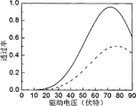
Fig. 3 is that Traditional IP S blue phase liquid crystal display (dotted line) and the two-sided IPS blue phase liquid crystal display of the present invention (solid line) are 1 μ m at electrode width among the embodiment 1, electrode separation is 1 μ m, and have identical blue phase liquid crystal material parameter and thickness of liquid crystal layer, both transmitances and voltage relationship figure contrast.
Fig. 4 is that Traditional IP S blue phase liquid crystal display (a) and the two-sided IPS blue phase liquid crystal display of the present invention (b) are 1 μ m at electrode width among the embodiment 1, electrode separation is 1 μ m, and have identical blue phase liquid crystal material parameter and thickness of liquid crystal layer, both transmission regions and light tight area planar figure contrast.
Fig. 5 is that Traditional IP S blue phase liquid crystal display (dotted line) and the two-sided IPS blue phase liquid crystal display of the present invention (solid line) are 1 μ m at electrode width among the embodiment 2, electrode separation is 2 μ m, and have identical blue phase liquid crystal material parameter and thickness of liquid crystal layer, both transmitances and voltage relationship figure contrast.
Fig. 6 is that Traditional IP S blue phase liquid crystal display (a) and the two-sided IPS blue phase liquid crystal display of the present invention (b) are 1 μ m at electrode width among the embodiment 2, electrode separation is 2 μ m, and have identical blue phase liquid crystal material parameter and thickness of liquid crystal layer, both transmission regions and light tight area planar figure contrast.
Fig. 7 is that Traditional IP S blue phase liquid crystal display (dotted line) and the two-sided IPS blue phase liquid crystal display of the present invention (solid line) are 2 μ m at electrode width among the embodiment 3, electrode separation is 1 μ m, and have identical blue phase liquid crystal material parameter and thickness of liquid crystal layer, both transmitances and voltage relationship figure contrast.
Fig. 8 is that Traditional IP S blue phase liquid crystal display (a) and the two-sided IPS blue phase liquid crystal display of the present invention (b) are 2 μ m at electrode width among the embodiment 3, electrode separation is 1 μ m, and have identical blue phase liquid crystal material parameter and thickness of liquid crystal layer, both transmission regions and light tight area planar figure contrast.
Fig. 9 is that Traditional IP S blue phase liquid crystal display (dotted line) and the two-sided IPS blue phase liquid crystal display of the present invention (solid line) are 2 μ m at electrode width among the embodiment 4, electrode separation is 2 μ m, and have identical blue phase liquid crystal material parameter and thickness of liquid crystal layer, both transmitances and voltage relationship figure contrast.
Figure 10 is that Traditional IP S blue phase liquid crystal display (a) and the two-sided IPS blue phase liquid crystal display of the present invention (b) are 2 μ m at electrode width among the embodiment 4, electrode separation is 2 μ m, and have identical blue phase liquid crystal material parameter and thickness of liquid crystal layer, both transmission regions and light tight area planar figure contrast.
Figure 11 is that Traditional IP S blue phase liquid crystal display (dotted line) and the two-sided IPS blue phase liquid crystal display of the present invention (solid line) are 3 μ m at electrode width among the embodiment 5, electrode separation is 2 μ m, and have identical blue phase liquid crystal material parameter and thickness of liquid crystal layer, both transmitances and voltage relationship figure contrast.
Figure 12 is that Traditional IP S blue phase liquid crystal display (a) and the two-sided IPS blue phase liquid crystal display of the present invention (b) are 3 μ m at electrode width among the embodiment 5, electrode separation is 2 μ m, and have identical blue phase liquid crystal material parameter and thickness of liquid crystal layer, both transmission regions and light tight area planar figure contrast.
Figure 13 is that Traditional IP S blue phase liquid crystal display (dotted line) and the two-sided IPS blue phase liquid crystal display of the present invention (solid line) are 3 μ m at electrode width among the embodiment 6, electrode separation is 3 μ m, and have identical blue phase liquid crystal material parameter and thickness of liquid crystal layer, both transmitances and voltage relationship figure contrast.
Figure 14 is that Traditional IP S blue phase liquid crystal display (a) and the two-sided IPS blue phase liquid crystal display of the present invention (b) are 3 μ m at electrode width among the embodiment 6, electrode separation is 3 μ m, and have identical blue phase liquid crystal material parameter and thickness of liquid crystal layer, both transmission regions and light tight area planar figure contrast.
Figure 15 is that Traditional IP S blue phase liquid crystal display (dotted line) and the two-sided IPS blue phase liquid crystal display of the present invention (solid line) are 4 μ m at electrode width among the embodiment 7, electrode separation is 3 μ m, and have identical blue phase liquid crystal material parameter and thickness of liquid crystal layer, both transmitances and voltage relationship figure contrast.
Figure 16 is that Traditional IP S blue phase liquid crystal display (a) and the two-sided IPS blue phase liquid crystal display of the present invention (b) are 4 μ m at electrode width among the embodiment 7, electrode separation is 3 μ m, and have identical blue phase liquid crystal material parameter and thickness of liquid crystal layer, both transmission regions and light tight area planar figure contrast.
Figure 17 is that Traditional IP S blue phase liquid crystal display (dotted line) and the two-sided IPS blue phase liquid crystal display of the present invention (solid line) are 4 μ m at electrode width among the embodiment 8, electrode separation is 4 μ m, and have identical blue phase liquid crystal material parameter and thickness of liquid crystal layer, both transmitances and voltage relationship figure contrast.
Figure 18 is that Traditional IP S blue phase liquid crystal display (a) and the two-sided IPS blue phase liquid crystal display of the present invention (b) are 4 μ m at electrode width among the embodiment 8, electrode separation is 4 μ m, and have identical blue phase liquid crystal material parameter and thickness of liquid crystal layer, both transmission regions and light tight area planar figure contrast.
Figure 19 is that Traditional IP S blue phase liquid crystal display (dotted line) and the two-sided IPS blue phase liquid crystal display of the present invention (solid line) are 1 μ m at electrode width among the embodiment 9, electrode separation is 4 μ m, and have identical blue phase liquid crystal material parameter and thickness of liquid crystal layer, both transmitances and voltage relationship figure contrast.
Figure 20 is that Traditional IP S blue phase liquid crystal display (dotted line) and the two-sided IPS blue phase liquid crystal display of the present invention (solid line) are 1 μ m at electrode width among the embodiment 10, electrode separation is 5 μ m, and have identical blue phase liquid crystal material parameter and thickness of liquid crystal layer, both transmitances and voltage relationship figure contrast.
Figure 21 is that Traditional IP S blue phase liquid crystal display (dotted line) and the two-sided IPS blue phase liquid crystal display of the present invention (solid line) are 2 μ m at electrode width among the embodiment 11, electrode separation is 5 μ m, and have identical blue phase liquid crystal material parameter and thickness of liquid crystal layer, both transmitances and voltage relationship figure contrast.
Figure 22 is that Traditional IP S blue phase liquid crystal display (dotted line) and the two-sided IPS blue phase liquid crystal display of the present invention (solid line) are 1 μ m at electrode width among the embodiment 12, electrode separation is 6 μ m, and have identical blue phase liquid crystal material parameter and thickness of liquid crystal layer, both transmitances and voltage relationship figure contrast.
Figure 23 is that Traditional IP S blue phase liquid crystal display (dotted line) and the two-sided IPS blue phase liquid crystal display of the present invention (solid line) are 2 μ m at electrode width among the embodiment 13, electrode separation is 6 μ m, and have identical blue phase liquid crystal material parameter and thickness of liquid crystal layer, both transmitances and voltage relationship figure contrast.
Embodiment
The structure of two-sided IPS blue phase liquid crystal display of the present invention is (as Fig. 1):
The two-sided IPS blue phase liquid crystal display of the present invention comprises (order from top to bottom): the polarizer 1, lower glass substrate 2, lower glass substrate inside surface strip ITO electrode 3 and 4, time insulation course 5, envelope frame adhesive 6, sept 7, blue phase liquid crystal layer 8, last insulation course 9, the basic inside surface strip of upper glass ITO electrode 10 and 11, top glass substrate 12, analyzer 13.
Require the strip ITO electrode 10 and 11 of top glass substrate inside surface to lay respectively at two adjacent strip ITO electrodes 3 of lower glass substrate inside surface and top, center, 4 gap in the two-sided IPS blue phase liquid crystal display of the present invention.Top glass substrate inside surface strip ITO electrode 11 is identical with 12 with electrode width, the electrode separation of lower glass substrate inside surface strip ITO electrode 3 and 4.
Down be full of blue phase liquid crystal layer 8 between insulation course 5 and the last insulation course 9 in the two-sided IPS blue phase liquid crystal display of the present invention, and the placement diameter is the thickness that the sept 7 of 10 μ m is controlled liquid crystal layer in blue phase liquid crystal layer 8.Insulation course is a silicon dioxide insulating layer, and thickness is bigger than the thickness of strip ITO electrode.
The two-sided IPS blue phase liquid crystal display of the present invention sample box method for making, make according to following steps:
Earlier on upper and lower ITO electro-conductive glass, apply photoresists respectively, cover lithography mask version (lithography mask version is to make the black corresponding with electrode pattern on film, and the clear area photoresist is reacted) again under the effect of light.During lithography mask version, make the zone of width 1 μ m, spacing 1 μ m earlier by lithography in following mask, the electrode separation center that mask makes by lithography under last mask correspondence makes the pattern of width 1 μ m by lithography then.And then shine by ultraviolet light, the ITO electrode layer is carried out the selective chemical corrosion, thereby on upper and lower ITO electro-conductive glass, obtain and the complete graph of a correspondence of upper and lower mask.
Spraying diameter with duster on lower glass substrate is the spherical resin powder of 10 μ m, form more evenly and distribute, control the spacing of upper and lower glass substrate, top glass substrate adopts method for printing screen to come silk-screen frame adhesive and conducting resinl, is used for controlling the size of made blue phase liquid crystal display spare and the public electrode between the conducting upper and lower base plate.
On the contraposition make-up machine, upper and lower glass substrate is carried out contraposition and fit, use thermal curing methods about 200 ℃, frame adhesive to be solidified, form the blue phase liquid crystal sylphon.
With nematic liquid crystal (49wt%Mreck BL038), chirality agent (21%Merck CB15 and 6%ZLI-4572) and prepolymer (9%EHA and 15%RM257) mix, under ultraviolet light, shine then, little by little form polymkeric substance at blue phase defective locations, this polymkeric substance has with the similar space structure of blue phase liquid crystal, and polymkeric substance can make blue phase liquid crystal be in a stable status.
Sylphon is placed in the liquid crystal filling confined chamber that vacuumizes, and the gas in the box is extracted out by sealing part, the blue phase liquid crystal that filling orifice (breach of sealed frame) contact is configured, blue phase liquid crystal material parameter: ε
//=37, ε
⊥=4, n
o=1.4744, n
e=1.7744, K=1.268nm/V
2(λ=550nm).Utilize capillarity, just most of volume of sylphon can be injected the blue phase liquid crystal material, to the indoor inert gases such as fully dry argon gas of process and nitrogen that charge into of liquid crystal filling, utilize the pressure of inert gas to make the blue phase liquid crystal material be full of liquid crystal cell fully again.Adopt that fluid sealant is bonding to seal, by freezing method, allow sealing compound shrink rightly to bring into seal in, solidify with UV-irradiation again.
Control UV-irradiation intensity and angle are carried out polymerization to the polymer monomer in the blue phase liquid crystal layer, form the polymkeric substance farmland line in the blue phase liquid crystal, the helical structure of blue phase liquid crystal is fixed, thus the blue phase state of acquisition wide temperature range.
Some sealing compounds, blue phase liquid crystal material and other dirt removals of blue phase liquid crystal box remained on surface are fallen.Just upper and lower polaroid can have been sticked then.The polarizer and analyzer all adopt G1220DU model polaroid, and the position angle of the polarizer is 45 °, and the position angle of analyzer is 135 °, and thickness is 230 μ m.
Obtain this two-sided IPS blue phase liquid crystal display at last.
It is known technology that above method for making is not stated content, specifically can be with reference to " the liquid crystal device technology basis " by publishing house of Beijing University of Post ﹠ Telecommunication publishes, model will is newly write.
The electrode width of the top glass substrate inside surface strip ITO electrode of the blue phase liquid crystal display of gained and lower glass substrate inside surface strip ITO electrode is 1 μ m, and electrode separation is 1 μ m; The blue phase liquid crystal layer thickness is 10 μ m, and the blue phase liquid crystal material parameter is ε
//=37, ε
⊥=4, n
o=1.4744, n
e=1.7744, K=1.268nm/V
2(λ=550nm).The polarizer and analyzer all adopt G1220DU model polaroid.The position angle of the polarizer is 45 °, and the position angle of analyzer is 135 °.
Fig. 2~Fig. 4 is electric field line distribution figure, transmitance and voltage relationship figure contrast, transmission region and the light tight area planar figure contrast that calculates Traditional IP S blue phase liquid crystal display and the two-sided IPS blue phase liquid crystal display of the present invention among the embodiment 1 by simulation softward (TechWiz LCD three-dimensional simulation software).
Traditional IP S blue phase liquid crystal display in the simulation applies different voltages (wherein a row replacement adds work voltage, and other does not apply voltage) on two adjacent strip ITO electrodes of lower glass substrate inside surface; The two-sided IPS blue phase liquid crystal display of the present invention applies different voltages (wherein a row replacement adds work voltage, and other does not apply voltage) respectively on two adjacent strip ITO electrodes of upper and lower glass substrate inside surface.
Fig. 2 is the electric field line distribution that calculates Traditional IP S blue phase liquid crystal display and the two-sided IPS blue phase liquid crystal display of the present invention by simulation softward.Fig. 2 (a) is a Traditional IP S blue phase liquid crystal display, between two adjacent strip ITO electrodes of lower glass substrate inside surface electric field line distribution is arranged; Fig. 2 (b) is the two-sided IPS blue phase liquid crystal display among the present invention, between two adjacent strip ITO electrodes of upper and lower glass substrate inside surface electric field line distribution is arranged all.
Fig. 3 is transmitance and the voltage relationship figure contrast that calculates Traditional IP S blue phase liquid crystal display and the two-sided IPS blue phase liquid crystal display of the present invention by simulation softward.Traditional IP S driving voltage of blue phase liquid crystal display is 84V, and transmitance is 45.6%; The driving voltage of the two-sided IPS blue phase liquid crystal display of the present invention is 66V, and transmitance is 92.0%.The driving voltage of the two-sided IPS blue phase liquid crystal display of the present invention has reduced by 21.4% than the driving voltage of Traditional IP S blue phase liquid crystal display, and transmitance increases by 46.4%.
Fig. 4 is transmission region and the light tight area planar figure contrast that calculates Traditional IP S blue phase liquid crystal display and the two-sided IPS blue phase liquid crystal display of the present invention by simulation softward.It is much bigger that the transmission region that the transmission region of blue phase liquid crystal display of the present invention accounts for Traditional IP S blue phase liquid crystal display among ratio Fig. 4 (a) of overall region among Fig. 4 (b) accounts for the ratio of overall region.
Embodiment 2-13
Two-sided IPS blue phase liquid crystal display the results are shown in Figure 5~Figure 23 and table 1 with the experiment test of Traditional IP S blue phase liquid crystal display under different electrode widths and electrode separation, and other is with embodiment 1.Fig. 5~Figure 18 be for the lower blue phase liquid crystal display of driving voltage as described in the embodiment 1-8, the transmitance of two-sided IPS blue phase liquid crystal display increases more than 30% (>85%) than the transmitance of Traditional IP S blue phase liquid crystal display; Figure 19~Figure 23 be for the bigger blue phase liquid crystal display of transmitance as described in the embodiment 9-13, the driving voltage of two-sided IPS blue phase liquid crystal display reduces more than 25% than the driving voltage of Traditional IP S blue phase liquid crystal display.
The present invention does not address part and is applicable to prior art.
Table 1:

Claims (7)
1. a two-sided IPS blue phase liquid crystal display is characterized by this LCD and comprises: the polarizer, analyzer, two-sided IPS blue phase liquid crystal box; Its position relation is followed successively by: the polarizer, two-sided IPS blue phase liquid crystal box, analyzer; Light is successively by the polarizer, two-sided IPS blue phase liquid crystal box, analyzer;
Described two-sided IPS blue phase liquid crystal box, thereon, the inside surface of lower glass substrate has strip tin indium oxide (ITO) electrode, two-sided IPS blue phase liquid crystal box comprises: top glass substrate, lower glass substrate, top glass substrate inside surface strip ITO electrode, lower glass substrate inside surface strip ITO electrode, go up insulation course, insulation course, blue phase liquid crystal layer, envelope frame adhesive down; Close its position: top glass substrate, top glass substrate inside surface strip ITO electrode, last insulation course, blue phase liquid crystal layer, envelope frame adhesive, lower glass substrate inside surface strip ITO electrode, following insulation course, lower glass substrate;
Described two-sided IPS blue phase liquid crystal box, the electrode width of top glass substrate inside surface strip ITO electrode, electrode separation are identical with electrode width, the electrode separation of lower glass substrate inside surface strip ITO electrode; The optional scope of electrode width: W=1~4 μ m; The optional scope of electrode separation: G=1~6 μ m; The strip ITO electrode of top glass substrate inside surface is positioned at top, two adjacent strip ITO electrode gaps of lower glass substrate inside surface center.
2. two-sided IPS blue phase liquid crystal display as claimed in claim 1 is characterized by described two-sided IPS blue phase liquid crystal box, and the strip ITO electrode of upper and lower glass substrate inside surface is embedded in respectively in the upper and lower insulation course.
3. two-sided IPS blue phase liquid crystal display as claimed in claim 1, the optional scope of the described blue phase liquid crystal layer thickness of its feature: d=5~20 μ m.Blue phase liquid crystal layer comprises: blue phase liquid crystal material and sept.
4. two-sided IPS blue phase liquid crystal display as claimed in claim 1, it is characterized by described blue phase liquid crystal layer medium blue phase liquid crystal material is the blue phase liquid crystal polymkeric substance.
5. two-sided IPS blue phase liquid crystal display as claimed in claim 1 is characterized by that sept is the spherical resin powder in the described blue phase liquid crystal layer, diameter range: Φ=5~20 μ m.
6. two-sided IPS blue phase liquid crystal display as claimed in claim 1 is characterized by described upper and lower glass substrate and relies on the glue bond of edge sealing frame together.
7. two-sided IPS blue phase liquid crystal display as claimed in claim 1, the polarizer that blue phase liquid crystal display adopted and the analyzer that it is characterized by described two-sided IPS pattern are the same model polaroid.
Priority Applications (1)
| Application Number | Priority Date | Filing Date | Title |
|---|---|---|---|
| CN 201010560578 CN101976005A (en) | 2010-11-25 | 2010-11-25 | Double-sided IPS blue phase liquid crystal display |
Applications Claiming Priority (1)
| Application Number | Priority Date | Filing Date | Title |
|---|---|---|---|
| CN 201010560578 CN101976005A (en) | 2010-11-25 | 2010-11-25 | Double-sided IPS blue phase liquid crystal display |
Publications (1)
| Publication Number | Publication Date |
|---|---|
| CN101976005A true CN101976005A (en) | 2011-02-16 |
Family
ID=43575901
Family Applications (1)
| Application Number | Title | Priority Date | Filing Date |
|---|---|---|---|
| CN 201010560578 Pending CN101976005A (en) | 2010-11-25 | 2010-11-25 | Double-sided IPS blue phase liquid crystal display |
Country Status (1)
| Country | Link |
|---|---|
| CN (1) | CN101976005A (en) |
Cited By (7)
| Publication number | Priority date | Publication date | Assignee | Title |
|---|---|---|---|---|
| CN102819155A (en) * | 2012-09-14 | 2012-12-12 | 深圳市华星光电技术有限公司 | Dual-TFT (Thin Film Transistor) substrate blue phase liquid crystal display panel |
| CN103293784A (en) * | 2012-02-29 | 2013-09-11 | 株式会社东芝 | Liquid crystal optical element and stereoscopic image display device |
| CN104216179A (en) * | 2014-09-12 | 2014-12-17 | 东莞通华液晶有限公司 | Ultra-wide-visual-angle and ultrahigh-contrast-ratio liquid crystal display control method and ultra-wide-visual-angle and ultrahigh-contrast-ratio liquid crystal display structure |
| CN104880883A (en) * | 2015-06-12 | 2015-09-02 | 武汉华星光电技术有限公司 | Blue-phase liquid crystal display panel and production method thereof |
| US9128340B2 (en) | 2012-09-14 | 2015-09-08 | Shenzhen China Star Optoelectronics Technology Co., Ltd. | Dual-TFT-substrate blue-phase liquid crystal display panel |
| CN104965360A (en) * | 2015-07-31 | 2015-10-07 | 深圳市华星光电技术有限公司 | Liquid crystal display panel and display |
| CN105093765A (en) * | 2015-08-26 | 2015-11-25 | 上海交通大学 | Method for electric control of polymerization process of polymer stabilized blue phase liquid crystal and device thereof |
Citations (4)
| Publication number | Priority date | Publication date | Assignee | Title |
|---|---|---|---|---|
| CN2424479Y (en) * | 1999-10-13 | 2001-03-21 | 中国科学院长春物理研究所 | High contrast fast response liquid crystal light valve |
| US6512503B1 (en) * | 1998-12-29 | 2003-01-28 | Hyundai Display Technology Inc. | Liquid crystal display |
| CN101718928A (en) * | 2009-12-29 | 2010-06-02 | 友达光电股份有限公司 | Electrode structure, display panel and dsiplay |
| CN201853034U (en) * | 2010-11-25 | 2011-06-01 | 河北工业大学 | Double-sided IPS (intrusion prevention system) blue phase liquid crystal display |
-
2010
- 2010-11-25 CN CN 201010560578 patent/CN101976005A/en active Pending
Patent Citations (4)
| Publication number | Priority date | Publication date | Assignee | Title |
|---|---|---|---|---|
| US6512503B1 (en) * | 1998-12-29 | 2003-01-28 | Hyundai Display Technology Inc. | Liquid crystal display |
| CN2424479Y (en) * | 1999-10-13 | 2001-03-21 | 中国科学院长春物理研究所 | High contrast fast response liquid crystal light valve |
| CN101718928A (en) * | 2009-12-29 | 2010-06-02 | 友达光电股份有限公司 | Electrode structure, display panel and dsiplay |
| CN201853034U (en) * | 2010-11-25 | 2011-06-01 | 河北工业大学 | Double-sided IPS (intrusion prevention system) blue phase liquid crystal display |
Cited By (13)
| Publication number | Priority date | Publication date | Assignee | Title |
|---|---|---|---|---|
| US9256074B2 (en) | 2012-02-29 | 2016-02-09 | Kabushiki Kaisha Toshiba | Liquid crystal optical element and stereoscopic image display device |
| CN103293784A (en) * | 2012-02-29 | 2013-09-11 | 株式会社东芝 | Liquid crystal optical element and stereoscopic image display device |
| WO2014040329A1 (en) * | 2012-09-14 | 2014-03-20 | 深圳市华星光电技术有限公司 | Dual-tft substrate blue phase liquid crystal display panel |
| CN102819155A (en) * | 2012-09-14 | 2012-12-12 | 深圳市华星光电技术有限公司 | Dual-TFT (Thin Film Transistor) substrate blue phase liquid crystal display panel |
| US9128340B2 (en) | 2012-09-14 | 2015-09-08 | Shenzhen China Star Optoelectronics Technology Co., Ltd. | Dual-TFT-substrate blue-phase liquid crystal display panel |
| CN104216179A (en) * | 2014-09-12 | 2014-12-17 | 东莞通华液晶有限公司 | Ultra-wide-visual-angle and ultrahigh-contrast-ratio liquid crystal display control method and ultra-wide-visual-angle and ultrahigh-contrast-ratio liquid crystal display structure |
| WO2016197419A1 (en) * | 2015-06-12 | 2016-12-15 | 武汉华星光电技术有限公司 | Blue-phase liquid crystal display panel and manufacturing method therefor |
| CN104880883A (en) * | 2015-06-12 | 2015-09-02 | 武汉华星光电技术有限公司 | Blue-phase liquid crystal display panel and production method thereof |
| US10134783B2 (en) | 2015-06-12 | 2018-11-20 | Wuhan China Star Optoelectronics Technology Co., Ltd. | Blue phase liquid crystal display panel and method for manufacturing the same |
| CN104965360A (en) * | 2015-07-31 | 2015-10-07 | 深圳市华星光电技术有限公司 | Liquid crystal display panel and display |
| WO2017020355A1 (en) * | 2015-07-31 | 2017-02-09 | 深圳市华星光电技术有限公司 | Liquid crystal display panel and display |
| US9933670B2 (en) | 2015-07-31 | 2018-04-03 | Shenzhen China Star Optoelectronics Technology Co., Ltd. | Liquid crystal display panel and display |
| CN105093765A (en) * | 2015-08-26 | 2015-11-25 | 上海交通大学 | Method for electric control of polymerization process of polymer stabilized blue phase liquid crystal and device thereof |
Similar Documents
| Publication | Publication Date | Title |
|---|---|---|
| CN101976005A (en) | Double-sided IPS blue phase liquid crystal display | |
| CN1991479B (en) | Liquid crystal display device and method for fabricating the same | |
| CN201853034U (en) | Double-sided IPS (intrusion prevention system) blue phase liquid crystal display | |
| CN101916010A (en) | Fast response IPS-VA liquid crystal display with high transmissivity | |
| JPH1062767A (en) | Liquid crystal display element and its production | |
| CN109521610A (en) | Display device and preparation method thereof | |
| TWI465821B (en) | Display panel and alignment method thereof | |
| CN103412434B (en) | A kind of transparent display and method for making | |
| JP2006171682A (en) | Liquid crystal display device | |
| CN104317090A (en) | Bi-stable state liquid crystal light valve and operation method thereof | |
| WO2015158052A1 (en) | Large board electrified circuit and manufacturing method therefor | |
| CN102636919B (en) | Liquid crystal display and method for manufacturing same | |
| US20080151150A1 (en) | Liquid crystal display panel and method for manufacturing thereof | |
| CN108459447A (en) | A kind of liquid crystal display device and preparation method thereof | |
| KR100824060B1 (en) | Bistable chiral splay nematic(bcsn) lcd having four terminal electrode | |
| CN102033366B (en) | Visual-angle-controllable patterned multi-domain vertical alignment (PMVA) liquid crystal display | |
| CN103499900B (en) | Liquid crystal panel and preparation method thereof, display | |
| CN109541860A (en) | A kind of display panel and preparation method thereof and display device | |
| CN101976006B (en) | Low-threshold-voltage and fast-response IPS-VA (In-Plane Switching-Vertical Alignment) liquid crystal display | |
| CN202025169U (en) | Visual angle controllable PMVA liquid crystal display | |
| CN201780434U (en) | Quick-response high-transmittance IPS-VA liquid crystal display | |
| CN103105688A (en) | Multi-domain twisted nematic liquid crystal display | |
| CN201853036U (en) | IPS-VA (in-plane switching vertical alignment) liquid crystal display with low threshold voltage and fast response | |
| CN211123547U (en) | Polarizer-free TN type liquid crystal display | |
| WO2013123890A1 (en) | Wide-viewing-angle liquid crystal display |
Legal Events
| Date | Code | Title | Description |
|---|---|---|---|
| C06 | Publication | ||
| PB01 | Publication | ||
| C10 | Entry into substantive examination | ||
| SE01 | Entry into force of request for substantive examination | ||
| C02 | Deemed withdrawal of patent application after publication (patent law 2001) | ||
| WD01 | Invention patent application deemed withdrawn after publication |
Open date: 20110216 |