CN101912209B - Muti-tray system for child's high chair and the high chair - Google Patents
Muti-tray system for child's high chair and the high chair Download PDFInfo
- Publication number
- CN101912209B CN101912209B CN2010102292379A CN201010229237A CN101912209B CN 101912209 B CN101912209 B CN 101912209B CN 2010102292379 A CN2010102292379 A CN 2010102292379A CN 201010229237 A CN201010229237 A CN 201010229237A CN 101912209 B CN101912209 B CN 101912209B
- Authority
- CN
- China
- Prior art keywords
- service plate
- high chair
- slot
- post
- service
- Prior art date
- Legal status (The legal status is an assumption and is not a legal conclusion. Google has not performed a legal analysis and makes no representation as to the accuracy of the status listed.)
- Active
Links
- 230000007246 mechanism Effects 0.000 claims description 33
- 238000005096 rolling process Methods 0.000 claims description 30
- 208000005168 Intussusception Diseases 0.000 claims description 2
- 235000012054 meals Nutrition 0.000 claims 2
- 238000004140 cleaning Methods 0.000 abstract description 3
- 230000037431 insertion Effects 0.000 abstract 1
- 238000003780 insertion Methods 0.000 abstract 1
- 230000008901 benefit Effects 0.000 description 11
- 238000006073 displacement reaction Methods 0.000 description 10
- 235000021185 dessert Nutrition 0.000 description 9
- 239000000463 material Substances 0.000 description 5
- 235000013305 food Nutrition 0.000 description 3
- XEEYBQQBJWHFJM-UHFFFAOYSA-N Iron Chemical compound [Fe] XEEYBQQBJWHFJM-UHFFFAOYSA-N 0.000 description 2
- 230000000694 effects Effects 0.000 description 2
- 238000003825 pressing Methods 0.000 description 2
- 125000006850 spacer group Chemical group 0.000 description 2
- 230000009471 action Effects 0.000 description 1
- 230000001154 acute effect Effects 0.000 description 1
- 230000015572 biosynthetic process Effects 0.000 description 1
- 230000008859 change Effects 0.000 description 1
- 230000000994 depressogenic effect Effects 0.000 description 1
- 238000007599 discharging Methods 0.000 description 1
- 238000005516 engineering process Methods 0.000 description 1
- 229910052742 iron Inorganic materials 0.000 description 1
- 238000012423 maintenance Methods 0.000 description 1
- 238000004519 manufacturing process Methods 0.000 description 1
- 238000000465 moulding Methods 0.000 description 1
Images


Classifications
-
- A—HUMAN NECESSITIES
- A47—FURNITURE; DOMESTIC ARTICLES OR APPLIANCES; COFFEE MILLS; SPICE MILLS; SUCTION CLEANERS IN GENERAL
- A47D—FURNITURE SPECIALLY ADAPTED FOR CHILDREN
- A47D1/00—Children's chairs
- A47D1/008—Children's chairs with trays
- A47D1/0081—Children's chairs with trays adjustable
-
- A—HUMAN NECESSITIES
- A47—FURNITURE; DOMESTIC ARTICLES OR APPLIANCES; COFFEE MILLS; SPICE MILLS; SUCTION CLEANERS IN GENERAL
- A47D—FURNITURE SPECIALLY ADAPTED FOR CHILDREN
- A47D1/00—Children's chairs
- A47D1/002—Children's chairs adjustable
-
- A—HUMAN NECESSITIES
- A47—FURNITURE; DOMESTIC ARTICLES OR APPLIANCES; COFFEE MILLS; SPICE MILLS; SUCTION CLEANERS IN GENERAL
- A47D—FURNITURE SPECIALLY ADAPTED FOR CHILDREN
- A47D1/00—Children's chairs
- A47D1/002—Children's chairs adjustable
- A47D1/004—Children's chairs adjustable in height
-
- A—HUMAN NECESSITIES
- A47—FURNITURE; DOMESTIC ARTICLES OR APPLIANCES; COFFEE MILLS; SPICE MILLS; SUCTION CLEANERS IN GENERAL
- A47D—FURNITURE SPECIALLY ADAPTED FOR CHILDREN
- A47D1/00—Children's chairs
- A47D1/008—Children's chairs with trays
- A47D1/0085—Children's chairs with trays removable
Abstract
A high chair is equipped with a tray system incorporating a multiple tray structure that is positionally adjustable relative to the high chair structure. The tray system includes a smaller lower tray formed with rearwardly extending, horizontal posts that are received within horizontally aligned sockets in the high chair structure. The distal ends of the tray posts are provided with rollers, and the high chair sockets have rollers, to provide for a smooth insertion of the posts into the sockets. The larger upper tray is detachably mounted on the lower tray for positional adjustment with the lower tray by releasing the tray posts for movement within the high chair sockets. The larger tray is formed with a depression to allow access to the position adjustment actuator. A third tray can be supported on the larger tray to facilitate cleaning of the tray system.
Description
The application's application number that to be applicant " Wonderland Nursery Goods " submit in China on February 18th, 2009 is 200910009333.X, and denomination of invention is divided an application for the application for a patent for invention of " the many service plates system and this high chair that are used for child's high chair ".
Technical field
The present invention relates to a kind of child's high chair, particularly relate to a kind of service plate system, comprise more than one service plate structure and have most the support columns that are provided with rolling member, so that be arranged at high chair.
Background technology
The child from the baby to even as big as stably be sitting in before the desk during; Parents can use Different products with auxiliary feeding, and a kind of such product is a high chair, and it often is used in baby and the child that toddles are supported on a higher position; So that the person of looking after feeding child easily; High chair is the unit that can stand alone, and it provides one to have the safety of feeding service plate and stable seating area, and the feeding service plate can remove from high chair so that the child is inserted high chair; Also be convenient to the cleaning of feeding service plate and high chair structure; But high chair engagement height guiding mechanism can be fit to the desk of differing heights so that seat can vertically adjust the position, so that service plate can be after high chair removes, the child position that is positioned on the high chair can be raised to corresponding desk.
High chair can provide different service plate functions; The structure of some high chair provides a less dessert service plate position below the high chair service plate that the typical case is bigger, and these dessert service plates are arranged on the seat of high chair and do not have by the function of adjustment position with the child that is fit to different size.Moreover because the dessert service plate is the seat that is set directly at high chair, the person of looking after need lift the child above the dessert service plate, just can make the child be seated in high chair or the child is shifted out high chair.Though some dessert service plates can remove by the seat from high chair under tool using situation not; But removing of dessert service plate needs the both hands operation usually; And the dessert service plate usually only just can not be removed under high chair uses the situation of food platter, for example when the child who is sitting in high chair by toward the height passed to corresponding desk the time.And the dessert service plate normally can't be adjusted the position, and food platter can be arranged on the dessert service plate usually with being adjusted the position.
It is to utilize column piece to reach being connected of service plate with the cooperation of slot that commercially available high chair has only some, and wherein, service plate is formed with the column piece that level backward protrudes out; Said column piece can supply to be contained in the slot that is formed at the high chair structure; This column piece follows the design of slot cooperation compared to the service plate that otherwise is provided with, and when its advantage was that desire is connected high chair with service plate, service plate was easier to alignment; And service plate also provides and high chair between firmer centre lock and connect so that product in use is able to stand the operating position of abuse; But even so, the fit system that column piece cooperates with slot neither be immaculate, and the service plate fixed form that column piece cooperates with slot is born bigger friction usually between column piece and slot; And before service plate is connected to the high chair seat, must activate the service plate guiding mechanism.
The problem of friction is usually by using the limited means of material different to solve service plate column piece and high chair slot; The problem of using material different to reduce friction; And the service plate fixed form that column piece cooperates with slot; Because of column piece often sticks, make service plate be difficult to the position of adjustment usually, at this moment with respect to high chair; Just can become sense of defeat and lose the wish that service plate integral body is removed of the person of looking after causes such value with removable service plate to be used or not by welcome by the person of looking after.
A kind of high chair with two service plate devices is disclosed in U.S. Patent number US5; 810; In 432, this case was checked and approved to Robert Haut and other people on September 22nd, 1998, this high chair have one be arranged on the high chair structure a following service plate and a bigger last service plate; Should go up service plate through one be fastened on play the service plate side latch mechanism be arranged on play service plate, this on service plate can adjust the position on the following service plate and need not move under service plate.Check and approve United States Patent (USP) case US6 to Pietro Catelli on December 24th, 2002; 497; In 452 a cases, two service plates of a kind of child's of being used in high chair are arranged and are disclosed, and the loam cake of this service plate is to be provided with removedly; One colludes the part setting is buckled in down service plate in order to will go up service plate, colludes part and comprises that a sliding members cooperates an exercisable slider and forms the actuated piece of high chair service plate guiding mechanism.
Provide one be provided with multiple service plate structure high chair service plate system need, and this service plate structure is positioned on the high chair easily, and a preferable use elasticity is provided.
Summary of the invention
An object of the present invention is to provide a kind of high chair with many service plates structure, this many service plates structure comprises the support column that is provided with rolling member, so that the service plate structure is fastened on high chair.
Another object of the present invention is to provide a kind of high chair service plate that rolling member supports that has, so that one-handed performance is positioned service plate on the high chair.
Of the present invention one be characterised in that the service plate post be provided with rolling member away from end.
Of the present invention another is characterised in that this high chair is formed with passage to accommodate said service plate post, and said passage is provided with a rolling member, in order to the service plate post of support level in the channel of high chair.
Of the present invention also another is characterised in that rolling member is arranged on the end of said service plate post, reaches rolling member and is arranged in the said passage, so that the slippage of service plate post in the high chair structure.
An advantage of the present invention is that the service plate structure can be made service plate be easy to be arranged on the high chair by one-handed performance.
Of the present invention another is characterised in that this service plate system has an actuating mechanism again, and this actuating mechanism is arranged on down in the service plate and is positioned at formation place of service plate post.
Another advantage of the present invention is that this many service plates structure utilizes the position of common actuating mechanism control service plate system with respect to the high chair structure.
Also another advantage of the present invention is that actuation control can be touched when bigger last service plate is arranged on the less following service plate.
Also another purpose of the present invention be to provide one be used for child's high chair two service plate structures, its allow go up service plate and down both positions of service plate adjust.
It is of the present invention that also another is characterised in that bigger last service plate is a lock bolt less and be formed with on the following service plate of service plate post.
Of the present invention another is characterised in that bigger last service plate forms a recess on its service plate structure again, and when this bigger last service plate was arranged on this time service plate, this position adjustment button can be touched.
The present invention also another advantage is that this time service plate can be gone up service plate and adjust the position to be fit to different big or small children together with bigger being somebody's turn to do.
Another advantage more of the present invention is down that service plate can be removed by high chair, so that the child is inserted or need not hold the child high service plate down when shifting out high chair.
Another advantage of the present invention is can be used and do not have a friction problem between service plate post and the high chair slot to the service plate of high chair service plate and slot setting.
Also another advantage of the present invention is that the position adjustment of service plate system can be accomplished easily under the situation that does not have retardance between service plate post and the high chair slot.
It is of the present invention that another is characterised in that the service plate system can not need the actuating of position adjusting mechanism can be set on the high chair structure.
Another purpose more of the present invention is to provide a kind of service plate system of the child's of being used for high chair, its structure durable, cheap for manufacturing cost, easy maintenance, be easy to assembling and simple, use effectively.
Through a kind of high chair that is provided with the service plate system is provided, and the service plate system is provided with many service plates structure that can supply with respect to high chair structural adjustment position, can be reached according to above-mentioned and other purpose, characteristic and advantage of the present invention.This service plate system comprises a less following service plate; This time service plate is formed with the service plate post that extends backward and be level; Said service plate post can flatly align and be housed in the slot that is positioned at the high chair structure; Said service plate post be provided with rolling member away from end, and the slot of high chair is provided with rolling member, provides the service plate post to stretch in the slot smoothly whereby.Bigger last service plate is separable to be arranged on down service plate and can to supply to adjust the position with play service plate by discharging the service plate post together in high chair slot intrinsic displacement.Bigger last service plate is formed with a recess and touches position adjustment actuated piece to allow.One the 3rd service plate can be set on the bigger last service plate, so that the cleaning of service plate system.
Description of drawings
By consult of the present invention below thin portion disclose, and graphic consulting below cooperating, advantage of the present invention can be understood undoubtedly, wherein:
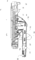
Fig. 1 is the front perspective view that realizes a high chair of the object of the invention;
Fig. 2 is the cutaway view through the slot of service plate post and high chair, is arranged on the high chair structure in order to the service plate system to be shown;
Fig. 3 is the cutaway view that the service plate system shifts out the high chair structure;
Fig. 4 is the side view with following service plate of service plate post, and the part-structure of service plate is removed can see the member in the service plate post down;
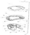
Fig. 5 service plate structure comprises following service plate, goes up on service plate and the service plate imbedding piece and look three-dimensional exploded view;
Fig. 6 is the following three-dimensional exploded view of looking of service plate structure shown in Figure 5;
Fig. 7 is the following parallax stereogram of service plate system;
Fig. 8 is a flat sheet of the bottom view of going up the following service plate after service plate removes;
Fig. 9 is the last parallax stereogram of position adjustment actuating mechanism, and the displacement of sliding connector is represented with imaginary line; And
The side view of Figure 10 service plate system, and the partial component of service plate system is removed knowing and sees that adjustment actuating mechanism in position extends through the service plate post.
The specific embodiment
Consult graphic; It is thus clear that realize a high chair of the object of the invention; High chair 10 can comprise a Z type framework 11, and Z type framework 11 has the roughly upright erection part 13 of extending of a base portion 12 and, and erection part 13 is connected with base portion 12 folders one acute angle; Erection part 13 comprises a pair of horizontal footing 17 separately; Said footing 17 is accommodated a flexible foot lever 14 respectively, and flexible foot lever 14 can receive the spring bias voltage and be in an extended position and offset the weight of seat element 20, thereby a child can take in seat element 20.Flexible foot lever 14 can be through a height adjustment latch mechanism 15 its positions with respect to footing 17 of control, height adjustment latch mechanism 15 have one be arranged on each flexible foot lever 14 actuated piece 16.Base portion 12 is preferably provided with one group of position at the directional wheel 19 of base portion 12 with footing 17 junctions of erection part 13, and a pair of in order to the wheel 18 of Z type framework 11 activity to be provided.
Z type framework 11 is supported in its top with a seat element 20; Seat element 20 be formed with one roughly be level seat portion 22; Seat portion 22 centers at the upstanding sidewall 23 of two sides by two cross sides that form handrail, receives a seat between two handrails 23 to lean against 25 at rear side and centers on.Open and the both legs when supplying to hold the child and taking seat portion 22 in the place ahead of seat element 20, and be formed with one and lean on portion 24 by the leading edge of seat portion 22 toward the pin that extends below.Pin leans on portion 24 to be preferably formed with extension of most horizontal directions in pairs and vertical direction holddown groove 26 separately, and said holddown groove 26 can supply a sole 27 to insert optionally to locate according to the size that rides in the child of seat element 20.Seat element 20 is supported on the Z-shaped framework 11; And its setting is to make sidewall 23; Particularly along the seat of seat element 20 lean against 25 can with Z type framework 11 at interval, Z-shaped framework 11 is preferably by wherein curved extension between flexible foot lever 14 to another flexible foot lever 14.
Preferably, lock bar element 43 is to receive the spring bias voltage and be in toward interior clamped position, and therefore, the person of looking after need grasp the position in the lock bar element 43 of each side and outwards pulling, to release from play the both sides of service plate 32, service plate 40 can be removed by quilts by following service plate 32.On the contrary, the external form of lock bar element 43 should be along inboard 44 and takes the form of inclined plane, and can be seated in down on the service plate 32 and pressed downward and being installed in down easily on the service plate 32 by going up service plate 40 so that go up service plate 40.The inboard 44 that described lock bar element 43 takes the form of inclined plane can be ordered about lock bar element 43 and outwards moved, and engages to allow its sidepiece with following service plate 32, forces lock bar element 43 entering clamped positions by the bias voltage of spring.
The upper surface 45 of last service plate 40 be depression and provide one frame arranged surface 45; To block food and other object, a service plate imbedding piece 47 can be set at upper surface 45, like Fig. 5 and shown in Figure 6; To provide one can remove easily and be convenient to clear up the surface of service plate 40; Service plate imbedding piece 47 can be formed with one toward the back flange 48 that extends below, and back flange 48 is provided with a spacer 49 of the heart therein, and service plate imbedding piece 47 is upper surfaces 45 of being arranged to just can insert service plate 40 depressions; And make back flange 48 make spacer 49 can be sticked in service plate 40 belows and removably service plate imbedding piece 47 is connected on the service plate 40 toward extending below along last service plate 40; Like Fig. 5 and shown in Figure 6, the external form of service plate imbedding piece 47 can be formed various zones, for example comprises that one can supply to place the border circular areas of cup.
Following service plate 32 is formed with a pair of laterally separately, backward the extension and the service plate post 35 of one-tenth level roughly; The shape of service plate post 35 is suitable for receiving in the corresponding slot 28 at the top that is formed on each handrail 23; Each service plate post 35 has one and is arranged on it away from the rolling member 36 of holding and be positioned at upper surface; When service plate post 35 stretched into slot 28, rolling member 36 combined with the upper surface of slot 28.Moreover each slot 28 comprises a rolling member 29, build the lower surface in the contiguous slot of handrail 23 structures 28 the place aheads in the rolling member 29 in, and is as shown in Figure 2, when service plate post 35 when slot 28 moves, rolling member 29 supports the bottom side of service plate posts 35.By a rolling member 36 and the rolling member 29 in slot 28 the place aheads at service plate post 35 ends, service plate post 35 can easily and nothing be frictionally mobile in slot 28.
From the viewpoint of a structure, following service plate 32 is service plate element 33 and the batter portions 34 at the opposition side that plays service plate 32 that are formed with a relatively flat, and batter portion 34 is higher than service plate post 35 tops of backward being extended by batter portion 34 with 33 supports of service plate element.The centre of following service plate 32 is formed with one by the limiting mechanism 39 that plays service plate 32 down to protrude out; Limiting mechanism 39 is in order to when service plate system 30 is arranged on high chair 10, and the child of agretope in seat 20 moves, and limiting mechanism 39 can be together with service plate element 33 with respect to seat portion 22 adjustment positions; Moreover; When service plate 32 was removed by high chair 10 instantly, all can hinder the member of the child being inserted a portion 22, for example service plate system 30 and limiting mechanisms 39 own; All remove, so that the child is inserted a portion 22 by high chair 10.
Rolling member 29,36 is to be preferred embodiment in the present invention; It has roller surface to reduce the friction problem between service plate post 35 and the slot 28 necessarily; Yet rolling member 29,36 also can be replaced by the embodiment of other antifriction element, for example; One or two rolling member 29,36 can be by wear-resisting, a for example Nai Long or the not imperial antifriction post of processing of iron (figure a does not show) replacement of low-friction coefficient material; It can slip in the antifriction groove (figure does not show) that is formed on slot top and service plate post 35 bottoms, has the contact point than less friction to provide between service plate post 35 and slot 28, so that the location of service plate system 30 and adjustment.
In addition, know this art and will understand, rolling member 36 is arranged on the top away from end of service plate post 35; Rolling member 29 is arranged on the place ahead lower surface of slot 28, is to see through the front end that batter portion 34 puts on service plate post 35 and play the weight of service plate 32, last service plate 40 and service plate imbedding piece 47, in the time of in service plate post 35 is arranged on slot 28; It forms the setting of a cantilever beam, and therefore, service plate post 35 can be skewed status in slot 28; So that service plate post 35 can be away from end to the end face pressurized of slot 28; And service plate post 35 is supported in the place ahead lower surface of slot 28, yet, by such arrangement; The place ahead that strength up is applied to service plate system 30 can make the service plate post 35 in slot 28 produce displacement slightly; Therefore, one optionally the 3rd rolling member (figure do not show) can be arranged in the lower surface of slot 28 and the position one be positioned at the rear of the place ahead rolling member 29 the precalculated position, so that support extra when service plate post 35 is contained in the slot 28 to be provided.
In the operation, service plate 32 is adjustable instantly when being arranged on high chair 10, because bigger last service plate 40 is arranged on the less following service plate 32, and allows that whole service plate system 30 is with respect to seat portion 22 adjustment positions, to be fit to different big or small children.This position adjustment actuating mechanism 50; Allow that service plate system 30 is under the situation of inoperation position adjustment actuating mechanism 50; Easily by with service plate post 35 alignment 28 and cooperate backward a strength that service plate post 35 is stretched in the slot 28 and be arranged on high chair 10, adjustment actuating mechanism 50 will have a more detailed explanation in following.Therefore, service plate system 30 can be arranged on one-handed performance on the high chair 10 by the person of looking after, and it is an important advantage for the person of looking after who has the child in arms, moreover following service plate 32 can be adjusted the position, rather than has only last service plate to be adjusted.
The lower surface of slot 28 is formed with the vertical opening separately of a row; In order to accommodate one be hubbed in each service plate post 35 and the position in its end away from the snap-fit element 55 of end; Said end is protruded service plate post 35 and is engaged in order to the opening with slot 28; An adjustment position of the corresponding service plate of opening system 30, preferably, the snap-fit element 55 that is pivoted engages with the opening of position in slot 28 by the bias voltage of a spring 56; So that service plate system 30 can be maintained at selected position, the state of snap-fit element 55 by the opening that is sticked in slot 28 released from up to the operation of carrying out a reality.
This forces snap-fit element 55 from being to be provided by an actuator arm 57 with the position in the practical operation that the opening of slot 28 lower surfaces engage release; Actuator arm 57 is arranged on each service plate post 35 and slides at a fore-and-aft direction; Actuator arm 57 is formed with a cam-like terminal 58; Said cam-like terminal 58 is provided with in order to be sticked in snap-fit element 55; And when actuator arm 57 slided backward, the biasing force that forces snap-fit element 55 opposing to be applied by spring 56 up pivoted, and the position, the place ahead of actuator arm 57 is formed with a holding section 59 of up extending.
As shown in Figure 2; The outer surface at the contiguous slots of handrail 23 28 places is to be up and to define a cam face toward rear-inclined and can be when service plate post 35 stretches into slot 28 for the first time and the end pressing of snap-fit element 55; Pressing between the end of cam face and snap-fit element 55 forces snap-fit element 55 to be pivoted in the service plate post 35 and resists biasing spring 56, makes snap-fit element 55 can not limit the displacement that service plate system 30 gets into slot 28.In view of the above; Other service plate post 35 is interior and slip over rolling member 29 because snap-fit element 55 will withdraw; Up to the end of snap-fit element 55 and first register in the slot 28; Thereupon, spring 56 will force snap-fit element 55 to be sticked in this first opening and block service plate post 35 and continue at 28 displacements backward in the slot.
Moreover, the displacement backward of service plate system 30 can follow by by pushing locking key 52 so that snap-fit element 55 withdrawal, reach the position that needs and accomplish up to service plate system 30.Preferably; The front side, end of snap-fit element 55 is a square end; Can make the vertical strength forward that puts on service plate system 30 be unlikely the end that produces cam effect and make snap-fit element 55 and eject slot 28 openings that engage with it; The end rear side of snap-fit element 55 is formed with a dorsal horn, applies backward vertical strength and causes snap-fit element 55 to eject the opening of the slot 28 that engages with it in order to avoid one.Therefore,, adjust the fore-and-aft direction of service plate system 30 or service plate system 30 is removed from high chair 10, just need operating position to adjust actuating mechanism 50 as long as snap-fit element 55 stretches in the slot 28 o'clock first openings in the alignment socket 28 for the first time at the service plate post.
To be appreciated that, be known this art after reading this specification, within scope of the present invention and purpose; Can make change to the arrangement of aforementioned content of the present invention and graphic details, material, step and member; Aforementioned graphic be preferred embodiment of the present invention, yet, based on the notion of present embodiment; Not departing within the scope of the present invention, also can be used in other embodiment.
Claims (17)
1. many service plates system that is used for child's high chair is characterized in that:
This high chair has a pair of horizontal handrail separately, and each handrail is formed with the slot of a longitudinal extension respectively, and this many service plates system comprises:
One first service plate element is formed with a pair of service plate post that extends and can align with said slot backward, is placed in said slot through said service plate post, and the said first service plate element can be at the relative handrail adjustment of longitudinal direction diverse location; And
One second service plate element is arranged at this first service plate element, makes this first service plate element can adjust the position with respect to this high chair with this second service plate element.
2. the many service plates system that is used for child's high chair as claimed in claim 1; It is characterized in that: wherein this second service plate element comprise a pair of laterally separately lock bar element; Said lock bar element setting makes this second service plate element be connected with this first service plate element in order to engage with this first service plate element.
3. the many service plates system that is used for child's high chair as claimed in claim 2 is characterized in that: wherein said lock bar element setting can be transverse to moving between a clamped position and the off-position, and said lock bar element receives bias voltage towards this clamped position.
4. the many service plates system that is used for child's high chair as claimed in claim 1 is characterized in that: this many service plates system also comprises
One first rolling member is arranged at each service plate post, when being used to this service plate post and stretching into this slot with the inner surface engaging of this corresponding slot; And
One second rolling member is arranged in this corresponding slot, when being used to this service plate post and stretching into this slot, engages with this service plate post.
5. the many service plates system that is used for child's high chair as claimed in claim 1; It is characterized in that: wherein this first service plate element comprises an actuating mechanism at position, a place ahead; This actuating mechanism is in order to adjust the position of this first service plate element with respect to this handrail; This second service plate element is formed with a recess, is protruded outward by this first service plate element to allow this actuating mechanism, and this actuating mechanism can be touched when this second service plate element is arranged at this first service plate element.
6. a high chair is characterized in that comprising
One seat element has a portion and a pair of horizontal handrail separately; And
The a meal disc system comprises that service plate can be arranged at said handrail with separating, and one can be arranged at this time service plate with separating last service plate, service plate is big than this time service plate on this,
Wherein this time service plate can carry out the diverse location adjustment with respect to this seat element, and service plate can be together with this time service plate with respect to this seat element adjustment on this thereby make.
7. high chair as claimed in claim 6; It is characterized in that: wherein this time service plate comprises an actuating mechanism at position, a place ahead; This actuating mechanism is in order to adjust this time service plate position of this seat element relatively, and service plate is formed with a recess on this, and the part of this actuating mechanism can be protruded through this second service plate element; So that when service plate was arranged at this time service plate on this, this actuating mechanism can be touched.
8. high chair as claimed in claim 7; It is characterized in that: wherein should go up service plate and comprise a pair of horizontal lock bar element separately; Releasable and this time tray latch of said lock bar element; Be fixed on this time service plate in order to will go up service plate, said lock bar element can laterally move between a clamped position and an off-position.
9. high chair is characterized in that comprising:
One seat element comprises the handrail of pair of spaced, and each handrail is formed with the slot of a longitudinal extension respectively;
The a meal disc system comprises a pair of service plate post that backward extends, and said service plate post can be connected with said slot versatilely, makes this service plate system carry out the diverse location adjustment with respect to this seat element; And
One limiting mechanism extends below by this service plate system is past, in order to adjust the position with this service plate system with respect to this seat element together.
10. high chair as claimed in claim 9; It is characterized in that: this high chair also comprises a position adjusting mechanism; Be sticked between this service plate system and this seat element; Supply this service plate system optionally to be positioned at most one of them position in the selective position with respect to this seat element, this position adjusting mechanism comprises an actuation element in an anterior position of this service plate system.
11. high chair as claimed in claim 10; It is characterized in that: wherein this service plate system comprises that service plate and is arranged at this time service plate and can be along with the last service plate that moves together; This actuation element is supported on this time service plate; Should go up service plate and comprise that one is formed on the recess of anterior position, when service plate was arranged at this time service plate on this, this actuation element can be touched through service plate protrusion on this by this time service plate.
12. high chair as claimed in claim 9 is characterized in that: wherein should go up service plate and also comprise:
A pair of horizontal lock bar element separately; Said lock bar element can with this time tray latch; Make that service plate is connected in this time service plate on this, said lock bar element can move between a clamped position and an off-position, and said lock bar element receives bias voltage towards this clamped position.
13. high chair as claimed in claim 12 is characterized in that: wherein should go up service plate ability intussusception in this time service plate, said lock bar element can operatively engage with the sidepiece of this time service plate.
14. high chair as claimed in claim 9 is characterized in that: wherein this time service plate also comprises:
The a pair of service plate post that backward extends, said service plate post is distinguished the said slot that can align; And
One first antifriction element; Be arranged at said service plate post and to should slot one of them; Stretch into said slot through said service plate post; This time service plate can be arranged at the position discretely at this seat element, and said antifriction dress element is in order to reduce the frictional force between each service plate post and its pairing slot.
15. high chair as claimed in claim 14; It is characterized in that: wherein each handrail have that one second antifriction element is arranged at wherein and the position at position, a place ahead; This second antifriction element engages with this service plate post when stretching into corresponding slot at this service plate post, this first antifriction element be arranged on this service plate post one away from end.
16. high chair as claimed in claim 15 is characterized in that: wherein this first antifriction element comprises one first rolling member, and this second antifriction element comprises one second rolling member.
17. high chair as claimed in claim 16 is characterized in that: wherein this first rolling member setting is in order to be sticked in a upper surface of corresponding slot, and this second rolling member setting is in order to be sticked in a lower surface of corresponding service plate post.
Applications Claiming Priority (2)
| Application Number | Priority Date | Filing Date | Title |
|---|---|---|---|
| US6630908P | 2008-02-19 | 2008-02-19 | |
| US61/066,309 | 2008-02-19 |
Related Parent Applications (1)
| Application Number | Title | Priority Date | Filing Date |
|---|---|---|---|
| CNA200910009333XA Division CN101513310A (en) | 2008-02-19 | 2009-02-18 | Muti-tray system and high chair for child's high chair |
Publications (2)
| Publication Number | Publication Date |
|---|---|
| CN101912209A CN101912209A (en) | 2010-12-15 |
| CN101912209B true CN101912209B (en) | 2012-05-09 |
Family
ID=40821747
Family Applications (3)
| Application Number | Title | Priority Date | Filing Date |
|---|---|---|---|
| CNA200910009333XA Pending CN101513310A (en) | 2008-02-19 | 2009-02-18 | Muti-tray system and high chair for child's high chair |
| CN2009100093344A Active CN101558947B (en) | 2008-02-19 | 2009-02-18 | Tray latch mechanism for high chair |
| CN2010102292379A Active CN101912209B (en) | 2008-02-19 | 2009-02-18 | Muti-tray system for child's high chair and the high chair |
Family Applications Before (2)
| Application Number | Title | Priority Date | Filing Date |
|---|---|---|---|
| CNA200910009333XA Pending CN101513310A (en) | 2008-02-19 | 2009-02-18 | Muti-tray system and high chair for child's high chair |
| CN2009100093344A Active CN101558947B (en) | 2008-02-19 | 2009-02-18 | Tray latch mechanism for high chair |
Country Status (4)
| Country | Link |
|---|---|
| US (2) | US8201879B2 (en) |
| EP (3) | EP2092858B1 (en) |
| JP (3) | JP5129177B2 (en) |
| CN (3) | CN101513310A (en) |
Families Citing this family (42)
| Publication number | Priority date | Publication date | Assignee | Title |
|---|---|---|---|---|
| US8201879B2 (en) * | 2008-02-19 | 2012-06-19 | Wonderland Nurserygoods Co., Ltd | Tray system for child's high chair |
| TWI417071B (en) * | 2010-11-04 | 2013-12-01 | Bp Childrens Prod Hk Co Ltd | Child high chair having a detachable pedal |
| JP2012096000A (en) * | 2010-11-04 | 2012-05-24 | Bp Children's Products Hk Co Ltd | Child high chair having detachable footrest |
| CN102599764A (en) * | 2011-01-21 | 2012-07-25 | 明门香港股份有限公司 | Combined type dinner plate |
| US20160270542A1 (en) * | 2011-07-22 | 2016-09-22 | Robert Foster | Spectator Tray |
| US9039079B2 (en) * | 2012-04-12 | 2015-05-26 | Mattel, Inc. | Children's tray with placement indicator |
| CN202919645U (en) * | 2012-05-02 | 2013-05-08 | 中山市隆成日用制品有限公司 | Infant chair back adjusting mechanism |
| US8696055B2 (en) * | 2012-09-14 | 2014-04-15 | Helen Of Troy Limited | Highchair with adjustable tray and seat height |
| KR101412975B1 (en) * | 2012-10-05 | 2014-06-27 | 김진성 | Multi tray for kids play of hard case shape |
| CN103126422B (en) * | 2013-03-08 | 2015-02-18 | 昆山小小恐龙儿童用品有限公司 | Spilt children dinning plate |
| CN104337282B (en) * | 2013-07-31 | 2017-08-08 | 明门香港股份有限公司 | Children's seat and its armrest adjusting device |
| USD742657S1 (en) | 2013-09-18 | 2015-11-10 | Graco Children's Products, Inc. | High chair |
| US9565929B2 (en) * | 2013-10-17 | 2017-02-14 | Regalo International, Llc | Dine and draw child lap tray apparatus |
| US9895005B2 (en) | 2014-05-21 | 2018-02-20 | Kids Ii, Inc. | Convertible child seat |
| US9560919B2 (en) * | 2014-08-01 | 2017-02-07 | Thorley Industries Llc | Infant chairs |
| US10588424B2 (en) | 2015-04-25 | 2020-03-17 | Kids2, Inc. | Convertible high chair |
| CN205866475U (en) * | 2015-04-25 | 2017-01-11 | 儿童二代公司 | Children strutting arrangement and be used for feeding tray rather than children that are used together |
| US11877671B2 (en) | 2015-04-25 | 2024-01-23 | Kids2, Inc. | Convertible high chair |
| US11723477B2 (en) | 2015-04-25 | 2023-08-15 | Kids2, Inc. | Convertible highchair |
| USD781059S1 (en) | 2015-11-24 | 2017-03-14 | Mattel, Inc. | Infant support structure |
| USD873503S1 (en) | 2016-04-04 | 2020-01-21 | Macneil Ip Llc | Pet feeding system |
| USD802853S1 (en) * | 2016-04-04 | 2017-11-14 | Macneil Ip Llc | Pet feeding system |
| USD873504S1 (en) | 2016-04-04 | 2020-01-21 | Macneil Ip Llc | Compact mat for pet feeding system |
| USD887650S1 (en) | 2016-04-04 | 2020-06-16 | Macneil Ip Llc | Pet water station |
| USD894498S1 (en) | 2016-04-04 | 2020-08-25 | Macneil Ip Llc | Single-bowl pet water/food station |
| USD873502S1 (en) | 2016-04-04 | 2020-01-21 | Macneil Ip Llc | Double bowl low-profile pet feeding station |
| DE102018204778B4 (en) | 2017-04-04 | 2019-06-27 | Wonderland Switzerland Ag | Multifunctional highchair |
| US10561254B2 (en) | 2017-04-04 | 2020-02-18 | Wonderland Switzerland Ag | Child tray assembly and multi-function high chair |
| CN107928246A (en) * | 2017-11-28 | 2018-04-20 | 好孩子儿童用品有限公司 | Children dinning chair |
| US10709259B2 (en) * | 2018-03-05 | 2020-07-14 | Wonderland Switzerland Ag | Latch mechanism and tray assembly |
| US10588425B1 (en) * | 2018-06-08 | 2020-03-17 | Angelica Jordan | Child seat system |
| CN108784128A (en) * | 2018-06-21 | 2018-11-13 | 东莞市鸿福物业管理服务有限公司 | Multipurpose highchair |
| US20200156279A1 (en) * | 2018-11-16 | 2020-05-21 | Corvesco Co. Ltd. | Cutting tool latch assembly |
| US11166570B1 (en) | 2019-03-19 | 2021-11-09 | Regalo International, Llc | High chair apparatus with wide foot print |
| US11641952B2 (en) | 2019-06-21 | 2023-05-09 | Kids2, Inc. | Modular cradle |
| USD880788S1 (en) * | 2019-08-19 | 2020-04-07 | David H. Price | Mat |
| USD880787S1 (en) * | 2019-08-19 | 2020-04-07 | David H. Price | Mat |
| US11589682B2 (en) | 2019-09-19 | 2023-02-28 | Thorley Industries, Llc | Infant chairs |
| USD958897S1 (en) | 2020-09-17 | 2022-07-26 | Kids2, Inc. | Modular toy bar |
| USD977865S1 (en) | 2020-09-17 | 2023-02-14 | Kids2, Inc. | Modular cradle |
| USD979259S1 (en) | 2020-09-17 | 2023-02-28 | Kids2, Inc. | Modular swing |
| CN112704355A (en) * | 2020-12-29 | 2021-04-27 | 鲍逸怡 | Assembly structure of dinner plate assembly and child dining chair |
Citations (4)
| Publication number | Priority date | Publication date | Assignee | Title |
|---|---|---|---|---|
| CN2164231Y (en) * | 1992-08-06 | 1994-05-11 | 铝光企业股份有限公司 | Chair for baby having meal |
| US5810432A (en) * | 1995-11-09 | 1998-09-22 | Graco Children's Products Inc. | High chair system |
| CN2484828Y (en) * | 2001-06-22 | 2002-04-10 | 李绍汉 | Quick assembled drawer |
| US6481790B2 (en) * | 2000-11-08 | 2002-11-19 | Kenny Cheng | Tray lock device |
Family Cites Families (35)
| Publication number | Priority date | Publication date | Assignee | Title |
|---|---|---|---|---|
| US1505518A (en) * | 1922-07-12 | 1924-08-19 | Jr Samuel T Workman | High chair |
| US1859150A (en) | 1931-03-31 | 1932-05-17 | Joseph V Moran | Baby chair |
| US2115860A (en) * | 1937-05-21 | 1938-05-03 | Kroll Samuel | Latch for high chair tables |
| US2440224A (en) * | 1945-03-26 | 1948-04-20 | Nat Lock Co | High chair tray slide |
| US2767774A (en) | 1952-03-13 | 1956-10-23 | George T Derby | High chair with tray attachment |
| US3239255A (en) * | 1964-04-06 | 1966-03-08 | Charles E Murcott | One directional movement catch device |
| US3580631A (en) * | 1969-02-10 | 1971-05-25 | Lumex | Invalid chair |
| US3635522A (en) * | 1969-09-29 | 1972-01-18 | Kerwit Medical Products Inc | Surgical treatment method and apparatus |
| JPH0336311Y2 (en) * | 1985-08-14 | 1991-08-01 | ||
| US4632451A (en) * | 1986-02-10 | 1986-12-30 | Lee Henry D | Wheelchair table and desk attachments |
| JPH0339090Y2 (en) * | 1986-10-22 | 1991-08-16 | ||
| US4807928A (en) | 1987-09-18 | 1989-02-28 | Gerico, Inc. | Tray apparatus for use with a chair |
| JPH0339091Y2 (en) * | 1988-12-27 | 1991-08-16 | ||
| IT1228724B (en) * | 1989-03-15 | 1991-07-03 | Cam Di Rho Gianfranco Aldo E M | Baby's high chair |
| US5238292A (en) | 1991-09-04 | 1993-08-24 | Gerry Baby Products Company | Highchair with adjustable seat |
| US5489138A (en) | 1993-10-01 | 1996-02-06 | Lisco, Inc. | Height adjustable high chair |
| US5468043A (en) * | 1994-08-16 | 1995-11-21 | Jina Manufacturer Thai Co., Ltd. | Foldable chair |
| US5527090A (en) * | 1994-11-04 | 1996-06-18 | Cosco, Inc. | Child seat tray assembly |
| US6293623B1 (en) * | 1997-09-26 | 2001-09-25 | Cosco Management, Inc. | Juvenile seat assembly |
| TW419983U (en) * | 2000-06-02 | 2001-01-21 | Link Treasure Ltd | Adjustable type structure of a dish for a meal seat |
| US6347833B1 (en) * | 2000-09-11 | 2002-02-19 | Trident Company Ltd. | High chair having a seat-tilting mechanism |
| US20020036416A1 (en) * | 2000-09-22 | 2002-03-28 | Andrew Mendenhall | Multi-piece accessory tray |
| US6419312B1 (en) * | 2000-10-27 | 2002-07-16 | Regalo International, Llc | Incrementally slidable high chair tray with quick release |
| IT250483Y1 (en) * | 2000-11-17 | 2003-09-10 | Artsana Spa | HIGH CHAIR WITH SHELF PROVIDED WITH REMOVABLE COVER ELEMENT |
| US6511124B2 (en) * | 2001-01-23 | 2003-01-28 | Mark Ellis Combs | Tray table for a child's car seat and associated methods |
| US6920830B1 (en) * | 2001-09-18 | 2005-07-26 | Mattel, Inc. | Removable tray insert and tray set |
| JP4014385B2 (en) * | 2001-10-16 | 2007-11-28 | 北川木工販売株式会社 | Infant chair |
| US20050006930A1 (en) * | 2003-03-26 | 2005-01-13 | Graco Children's Products Inc. | High chair |
| JP2005027764A (en) * | 2003-07-09 | 2005-02-03 | Showa Prod:Kk | Foldable table, drawer type seat, and table with seat |
| CA2465939C (en) * | 2004-04-30 | 2010-08-24 | Mattel, Inc. | Infant support with selectively covered tray |
| TWM258666U (en) * | 2004-05-13 | 2005-03-11 | Huei-Min Jhou | A multi-functional dining chair for children |
| US7261370B1 (en) * | 2004-12-03 | 2007-08-28 | Whitesell Jr Robert C | High chair apparatus |
| CN2794336Y (en) * | 2005-01-31 | 2006-07-12 | 上海统资电器有限公司 | Height regulator structure of baby high leg chair |
| CN2907410Y (en) * | 2006-06-13 | 2007-06-06 | 明门实业股份有限公司 | Retractable long-leg chair with locking device |
| US8201879B2 (en) * | 2008-02-19 | 2012-06-19 | Wonderland Nurserygoods Co., Ltd | Tray system for child's high chair |
-
2009
- 2009-02-07 US US12/367,514 patent/US8201879B2/en active Active
- 2009-02-07 US US12/367,516 patent/US7922244B2/en active Active
- 2009-02-17 JP JP2009034067A patent/JP5129177B2/en active Active
- 2009-02-18 CN CNA200910009333XA patent/CN101513310A/en active Pending
- 2009-02-18 EP EP09153127.7A patent/EP2092858B1/en active Active
- 2009-02-18 CN CN2009100093344A patent/CN101558947B/en active Active
- 2009-02-18 JP JP2009035226A patent/JP5468791B2/en active Active
- 2009-02-18 EP EP13154829.9A patent/EP2606773A1/en not_active Withdrawn
- 2009-02-18 EP EP09153125.1A patent/EP2092857B1/en active Active
- 2009-02-18 CN CN2010102292379A patent/CN101912209B/en active Active
-
2012
- 2012-08-21 JP JP2012182110A patent/JP5524297B2/en active Active
Patent Citations (4)
| Publication number | Priority date | Publication date | Assignee | Title |
|---|---|---|---|---|
| CN2164231Y (en) * | 1992-08-06 | 1994-05-11 | 铝光企业股份有限公司 | Chair for baby having meal |
| US5810432A (en) * | 1995-11-09 | 1998-09-22 | Graco Children's Products Inc. | High chair system |
| US6481790B2 (en) * | 2000-11-08 | 2002-11-19 | Kenny Cheng | Tray lock device |
| CN2484828Y (en) * | 2001-06-22 | 2002-04-10 | 李绍汉 | Quick assembled drawer |
Also Published As
| Publication number | Publication date |
|---|---|
| JP2009195698A (en) | 2009-09-03 |
| US20090206638A1 (en) | 2009-08-20 |
| EP2092857A3 (en) | 2012-03-28 |
| CN101558947B (en) | 2013-01-23 |
| EP2092858B1 (en) | 2018-05-30 |
| JP5129177B2 (en) | 2013-01-23 |
| CN101558947A (en) | 2009-10-21 |
| EP2092858A2 (en) | 2009-08-26 |
| JP5468791B2 (en) | 2014-04-09 |
| CN101912209A (en) | 2010-12-15 |
| EP2606773A1 (en) | 2013-06-26 |
| JP2009195696A (en) | 2009-09-03 |
| US20090206639A1 (en) | 2009-08-20 |
| EP2092857A2 (en) | 2009-08-26 |
| JP5524297B2 (en) | 2014-06-18 |
| JP2012223624A (en) | 2012-11-15 |
| US8201879B2 (en) | 2012-06-19 |
| US7922244B2 (en) | 2011-04-12 |
| EP2092857B1 (en) | 2013-11-20 |
| CN101513310A (en) | 2009-08-26 |
| EP2092858A3 (en) | 2012-03-28 |
Similar Documents
| Publication | Publication Date | Title |
|---|---|---|
| CN101912209B (en) | Muti-tray system for child's high chair and the high chair | |
| US9498064B2 (en) | Swivel feeding seat | |
| JP3416329B2 (en) | Child seat device | |
| US7104603B2 (en) | Booster seat | |
| EP2046167B1 (en) | Modular highchair with height adjustment | |
| CN201304957Y (en) | Safety belt adjusting device | |
| TW201410186A (en) | Highchair with adjustable tray and seat height | |
| US6715827B1 (en) | Backrest adjusting mechanism used in high chair for infants, toddlers, and small children | |
| GB2439280A (en) | High chair with adjustable backrest | |
| US20080224512A1 (en) | Lock for Forward-Folding Backrest | |
| CN201303752Y (en) | High chair | |
| CN2882425Y (en) | High-leg dining chair for child | |
| EP4098153A1 (en) | Foldable small dining chair | |
| CN220800609U (en) | Crib handrail group and be equipped with crib of this handrail group | |
| JP4578616B2 (en) | table | |
| EP4166045B1 (en) | Multifunctional foldable highchair | |
| JP2509547Y2 (en) | Infant chair reclining mechanism | |
| JPH0753558Y2 (en) | Baby chair with table | |
| CN208640148U (en) | A kind of adjustable baby dining chair of chair angle | |
| CN116350037A (en) | High chair with adjustable and detachable dinner plate | |
| CN113100599A (en) | Armrest cushion with multi-directional adjustment | |
| KR20180062500A (en) | Slide chair tilt sink in response to weight | |
| JP2003144233A (en) | Table and its housing method |
Legal Events
| Date | Code | Title | Description |
|---|---|---|---|
| C06 | Publication | ||
| PB01 | Publication | ||
| C10 | Entry into substantive examination | ||
| SE01 | Entry into force of request for substantive examination | ||
| C14 | Grant of patent or utility model | ||
| GR01 | Patent grant |