CN101867864A - Video/audio input/output system - Google Patents
Video/audio input/output system Download PDFInfo
- Publication number
- CN101867864A CN101867864A CN201010164252A CN201010164252A CN101867864A CN 101867864 A CN101867864 A CN 101867864A CN 201010164252 A CN201010164252 A CN 201010164252A CN 201010164252 A CN201010164252 A CN 201010164252A CN 101867864 A CN101867864 A CN 101867864A
- Authority
- CN
- China
- Prior art keywords
- audio
- video
- output
- signal
- input
- Prior art date
- Legal status (The legal status is an assumption and is not a legal conclusion. Google has not performed a legal analysis and makes no representation as to the accuracy of the status listed.)
- Pending
Links
- 230000005236 sound signal Effects 0.000 claims abstract description 44
- 238000009434 installation Methods 0.000 claims abstract description 21
- 239000000284 extract Substances 0.000 claims description 6
- 238000000605 extraction Methods 0.000 claims description 6
- 230000003292 diminished effect Effects 0.000 claims description 3
- 230000003247 decreasing effect Effects 0.000 abstract 1
- 101000984186 Homo sapiens Leukocyte immunoglobulin-like receptor subfamily B member 4 Proteins 0.000 description 9
- 102100025578 Leukocyte immunoglobulin-like receptor subfamily B member 4 Human genes 0.000 description 9
- 238000005516 engineering process Methods 0.000 description 7
- 238000012986 modification Methods 0.000 description 3
- 230000004048 modification Effects 0.000 description 3
- 230000002860 competitive effect Effects 0.000 description 2
- 230000008878 coupling Effects 0.000 description 2
- 238000010168 coupling process Methods 0.000 description 2
- 238000005859 coupling reaction Methods 0.000 description 2
- 238000010586 diagram Methods 0.000 description 2
- 238000005259 measurement Methods 0.000 description 2
- 235000004522 Pentaglottis sempervirens Nutrition 0.000 description 1
- 238000004364 calculation method Methods 0.000 description 1
- 238000000205 computational method Methods 0.000 description 1
- 230000001934 delay Effects 0.000 description 1
- 238000000034 method Methods 0.000 description 1
- 239000000725 suspension Substances 0.000 description 1
- 230000000007 visual effect Effects 0.000 description 1
Images


Classifications
-
- H—ELECTRICITY
- H04—ELECTRIC COMMUNICATION TECHNIQUE
- H04N—PICTORIAL COMMUNICATION, e.g. TELEVISION
- H04N7/00—Television systems
- H04N7/18—Closed-circuit television [CCTV] systems, i.e. systems in which the video signal is not broadcast
- H04N7/181—Closed-circuit television [CCTV] systems, i.e. systems in which the video signal is not broadcast for receiving images from a plurality of remote sources
-
- H—ELECTRICITY
- H04—ELECTRIC COMMUNICATION TECHNIQUE
- H04S—STEREOPHONIC SYSTEMS
- H04S3/00—Systems employing more than two channels, e.g. quadraphonic
- H04S3/002—Non-adaptive circuits, e.g. manually adjustable or static, for enhancing the sound image or the spatial distribution
-
- H—ELECTRICITY
- H04—ELECTRIC COMMUNICATION TECHNIQUE
- H04R—LOUDSPEAKERS, MICROPHONES, GRAMOPHONE PICK-UPS OR LIKE ACOUSTIC ELECTROMECHANICAL TRANSDUCERS; DEAF-AID SETS; PUBLIC ADDRESS SYSTEMS
- H04R2205/00—Details of stereophonic arrangements covered by H04R5/00 but not provided for in any of its subgroups
- H04R2205/024—Positioning of loudspeaker enclosures for spatial sound reproduction
-
- H—ELECTRICITY
- H04—ELECTRIC COMMUNICATION TECHNIQUE
- H04R—LOUDSPEAKERS, MICROPHONES, GRAMOPHONE PICK-UPS OR LIKE ACOUSTIC ELECTROMECHANICAL TRANSDUCERS; DEAF-AID SETS; PUBLIC ADDRESS SYSTEMS
- H04R5/00—Stereophonic arrangements
- H04R5/027—Spatial or constructional arrangements of microphones, e.g. in dummy heads
-
- H—ELECTRICITY
- H04—ELECTRIC COMMUNICATION TECHNIQUE
- H04S—STEREOPHONIC SYSTEMS
- H04S2400/00—Details of stereophonic systems covered by H04S but not provided for in its groups
- H04S2400/15—Aspects of sound capture and related signal processing for recording or reproduction
Abstract
Provided is a video/audio input/output system including a video/audio input system including a video input device and a plurality of audio input devices and a video/audio output system including a video output device having a display surface, the video output device being for outputting a video on the display surface based on a video signal obtained by the video input device, and a plurality of audio output devices respectively corresponding to the plurality of audio input devices. The plurality of audio output devices are each installed at a location determined by decreasing or increasing, according to a reduction rate or an enlargement rate of the video to a real size and with a centre of the video as a reference, a distance from the centre of the video to a foot of a perpendicular drawn from the location of installation of the corresponding audio input device to the display surface, and the plurality of audio output devices output audio based on the audio signals obtained by the corresponding audio input devices.
Description
Technical field
The present invention relates to a kind of video/audio input/output system.
Background technology
Usually, for concert hall of passing on the mass viewer audiences gathering or the situation of holding the place of competitive sports, use inner video that obtains of floor and the audio frequency of collecting at the scene and obtaining.Spectators are by obtaining to listen to the situation that the audio frequency that obtains can be understood the scene in the video watching.
For example, the technology of output spectators listening to audio is used stereo, 5.1-sound channel surround sound, 6.1-sound channel surround sound, 7.1-sound channel surround sound etc.According to this technology, spectators can listening to audio, feel he seem actual just at the scene.Various other the technology (for example referring to JP2007-208318A) of output audio are disclosed.
Summary of the invention
Yet,, be difficult to audiovideo is positioned (localize) video according to above-mentioned technology.By listening to the audio frequency from video output when watching video, actual not at the scene spectators can experience on-the-spot situation truly.If the audio ﹠ video of output mated at that time, spectators can experience on-the-spot situation more realistically.For realizing this point, it is very important that audiovideo is positioned video.
Therefore,, be desirable to provide a kind of new improvement technology, make the user can experience the situation in the place of carrying out shooting and sound collecting truly by when watching captured video, listening to collected audio frequency according to above-mentioned situation.
According to embodiments of the invention, a kind of video/audio input/output system is provided, comprise: the video/audio input system, comprise a video input device and a plurality of voice input device, described video input device is taken along specific direction with specific magnification ratio and is obtained video, the video that obtains is converted to the signal of telecommunication, and obtain electrical signal converted as vision signal, described a plurality of voice input device be installed in aspect the horizontal range of the infield of video input device with in a plurality of places different aspect the height, vibration around described a plurality of voice input device detects, the vibration that detects is converted to the signal of telecommunication, and obtain electrical signal converted as audio signal; The video/audio output system, comprise a video output device and a plurality of audio output device, described video output device has display surface, the vision signal that described video output device obtains based on video input device is at described display surface output video, and described a plurality of audio output devices correspond respectively to described a plurality of voice input device.Described a plurality of audio output device is installed on separately, reduce ratio or magnification ratio as benchmark and according to described video with respect to full-size(d) with the center of described video, reduce or increase from the center of described video to from the installation site of respective audio input unit to the distance of the intersection point of the drawn vertical line of described display surface and definite position, the audio signal that described a plurality of audio output devices obtain based on the respective audio input unit and output audio.
Described a plurality of audio output device can be installed on and make the direction of audio frequency output towards the center of described video.
The video/audio output system also can comprise: output-controlling device, make the corresponding time of distance between the installation site of the output time delay of audio frequency and specified place and described a plurality of voice input devices, and make corresponding a plurality of audio output device export described audio frequency.
The video/audio output system also can comprise: output-controlling device, the volume of audio frequency is diminished and the installation site of specified place and described a plurality of voice input devices between the corresponding volume down of distance in a small amount, and make corresponding a plurality of audio output device export described audio frequency.
Described specified place can be the point that the described center of described video shows.
The video/audio input system also can comprise input control device, produce audio/video signal by combination by the vision signal of video input device acquisition and each audio signal that obtains by described a plurality of voice input devices, and an audio/video signal that produces is recorded in recording medium, the video/audio output system also can comprise output-controlling device, be used for the audio/video signal of reading and recording at recording medium, from the audio/video signal that reads, extract each audio signal and vision signal, the vision signal of extracting is exported to video output device, simultaneously the audio signal output of each extraction is given and each the corresponding audio output device of each voice input device that obtains described audio signal, described video output device can be based on the vision signal of output-controlling device output at the display surface output video, and described a plurality of audio output devices can come output audio based on the audio signal of described output-controlling device output.
The video/audio input system also can comprise input control device, produce audio/video signal by combination by the vision signal of video input device acquisition and each audio signal that obtains by described a plurality of voice input devices, and a video/audio signal that produces sends to the video/audio output system, the video/audio output system also can comprise output-controlling device, be used to receive the audio/video signal that sends from the video/audio input system, from the audio/video signal that receives, extract each audio signal and vision signal, the vision signal of extracting is exported to video output device, simultaneously the audio signal output of each extraction is given and each the corresponding audio output device of each voice input device that obtains audio signal, described video output device can be based on the vision signal of being exported by output-controlling device at described display surface output video, and described a plurality of audio output devices can come output audio based on the audio signal of described output-controlling device output.
According to the invention described above embodiment, make spectators can when watching capture video, listen to the audio frequency of collection with the situation of sense of reality to the place of carrying out shooting and sound collecting.
Description of drawings
Fig. 1 is the configuration diagram according to the video/audio input/output system of present embodiment;
Fig. 2 is a diagrammatic sketch of representing how to install the example of voice input device;
Fig. 3 is a diagrammatic sketch of representing how to install the example of audio output device;
Fig. 4 describes the volume of output audio and the diagrammatic sketch of the calculating of time of delay;
Fig. 5 is the diagrammatic sketch of expression with respect to corresponding relation between the distance of datum mark and the range attenuation degree (volume down in a small amount);
Fig. 6 is the diagrammatic sketch of expression with respect to corresponding relation between the distance of datum mark and the delay compensation amount (time of delay);
Fig. 7 is the diagrammatic sketch that concerns between the virtual and physical location of expression center microphone installation.
Embodiment
Below describe the preferred embodiments of the present invention with reference to the accompanying drawings.It is noted that in this specification and the accompanying drawing that the structural detail with essentially identical function and structure is represented by same numeral, and omitted the explanation that these structural details are repeated.In addition, explain according to the following order that illustrates.
1, first embodiment
The structure of 1-1, video/audio input/output system
The structure of 1-2, video/audio input system
The structure of 1-3, video/audio output system
The volume of 1-4, output audio and the calculating of time of delay
2, the modification example of first embodiment
3, conclusion
<1, first embodiment 〉
The first embodiment of the present invention is described.
(structure of 1-1, video/audio input/output system)
Fig. 1 is the configuration diagram according to the video/audio input/output system of present embodiment.As shown in Figure 1, the video/audio input/output system 1 according to present embodiment comprises: video/audio input system 100 and video/audio output system 200.For example, video/audio input system 100 is the systems that are installed on the concert hall that mass viewer audiences will assemble, the place that will hold competitive sports etc.Yet the place that video/audio input system 100 is installed is not limited to these places, can be can obtain and will be watched and the video listened to and any place of audio frequency by spectators.
Video/audio output system 200 is spectators are watched and to listen to the video that obtains by video/audio input system 100 and the system of audio frequency.For example, suppose such situation: can't go to the scene or can't enter on-the-spot spectators to be gathered in place, and the spectators that assemble watch on-the-spot situation together away from the scene.Therefore, video/audio output system 200 should be installed in the place away from the place that video/audio input system 100 is installed.For example, when spectators' quantity surpasses 1,000, suppose that video/audio output system 200 is installed in broad place.Yet, when spectators' quantity only has the several people, suppose that video/audio output system 200 is installed in less space, such as single spectators' family.
(structure of 1-2, video/audio input system)
Video/audio input system 100 comprises video input device 110 and a plurality of voice input device 120 at least.Below see figures.1.and.2 and describe each device of structure video/audio input system 100.
Fig. 2 is a diagrammatic sketch of representing how to install the example of voice input device.As shown in Figure 2, voice input device 120 is installed in for example each position in football field, as low microphone LM1 to LM7, center microphone CM8, middle microphone MM9 to MM17 and high microphone HM18 and HM19.In the example shown in Fig. 2, low microphone LM1 is installed on court level (low-level) to LM7 and center microphone CM8, middle microphone MM9 is installed on grandstand level (by-level) to MM17, and high microphone HM18 and HM19 are installed on ceiling level (high level).That is to say, realize sound collecting, use 19 sound channels altogether: 8 sound channel surround sounds of court level (low-level), 9 sound channel surround sounds of grandstand level (by-level), and 2 channel stereo of ceiling level (high level) in following mode.
Court level (low-level), grandstand level (by-level) and ceiling level (high level) differ from one another aspect height.By being reproduced in the audio frequency that three levels (that is, court level (low-level), grandstand level (by-level) and ceiling level (high level)) are collected, the situation of the match of can the true reappearance football field carrying out.The quantity of level is three in the example though illustrate at Fig. 2, and the quantity of level is not limited to three, and can be to surpass one any amount.In addition, be horizontally disposed with at each and surpass a microphone and be enough to.In addition,, realize center microphone CM8 in the following manner in order to prevent to interfere with play: according to cubical antenna configuration center microphone CM8, and at certain distance suspension cubical antenna.
Getting back to Fig. 1 continues to explain.Video input device 110 obtains video by taking along specific direction with specific magnification ratio, and the video that obtains is converted to the signal of telecommunication, and obtains electrical signal converted as vision signal.Described specific direction is not particularly limited, and can be defined as watching the desired direction of watching of spectators of video input device 110 capture video arbitrarily.In addition, described specific magnification ratio is not particularly limited, and can be defined as watching the desired magnification ratio of watching of spectators of video input device 110 capture video arbitrarily.Yet video input device 110 is taken along specific direction with specific magnification ratio, therefore, has obtained the video of establishing shot specific region.The installation site of video input device 110 is not particularly limited, and can be defined as watching the desirable position of spectators of video input device 110 capture video arbitrarily.For example, video input device 110 can be installed in front, VIP seat.For example, use camera to wait and dispose video input device 110.
A plurality of voice input devices 120 are installed on the horizontal range aspect of the infield of video input device 110 with in a plurality of places different aspect the height, vibration around a plurality of voice input devices 120 detect, the vibration that detects is converted to the signal of telecommunication, and obtain electrical signal converted as audio signal.For example, vibration on every side is the vibration of the medium (for example, air) adjacent with voice input device 120.For example, use structure voice input device 120 such as microphone.In the example shown in Fig. 2, low microphone LM1 is installed on different height to MM17 and high microphone HM18 with HM19 to LM7, center microphone CM8, middle microphone MM9.In addition, in the example shown in Fig. 2, microphone (low microphone LM1 to LM7, center microphone CM8, middle microphone MM9 to MM17 and high microphone HM18 and HM19) is installed on and installs a plurality of places that the horizontal range of the position (for example, in front, VIP seat) of video input device 110 differs from one another.
(structure of 1-3, video/audio output system)
Video/audio output system 200 comprises video output device 210 and a plurality of audio output device 220 at least.Following each device of describing structure video/audio output system 200 with reference to Fig. 1 and Fig. 3.
Fig. 3 is a diagrammatic sketch of representing how to install the example of audio output device.As shown in Figure 3, audio output device 220 is installed in the display surface 211 of video output device 210 or is installed in the extended position of display surface 211, as loud speaker S1 to S19.In the example shown in Fig. 3, loud speaker S8 is installed in the display surface 211, and other loud speaker S1 to S7 and S9 to S19 are installed in the extended position of display surface 211.Loud speaker S8 is installed in the position of the center microphone CM8 that occurs in the video according to display surface 211 demonstrations.In a similar manner, when supposing that the zone of taking is infinitely extended, the position of each microphone that occurs in the video that shows according to display surface 211 (low microphone LM1 to LM7, middle microphone MM9 to MM17 and high microphone HM18 and HM19), installation loud speaker S1 to S7 and S9 to S19.Though Fig. 3 illustrates display surface in the example (screen) 211 and is of a size of width 100m and height 20m, this size is not limited thereto.In addition, in the example shown in Fig. 3,, audio output device 220 (loud speaker S1 to S19) is installed in the direction that allows audio frequency output towards the shown video hub of display surface 211.
Getting back to Fig. 1 continues to explain.Video output device 210 comprises display surface 211, and the vision signal that obtains based on video input device 110 is at display surface 211 output videos.For example, the use display unit (such as, large-screen or television set) construct video output device 210, but the type of video output device 210 is not subjected to concrete restriction.
A plurality of audio output devices 220 correspond respectively to a plurality of voice input devices 120.A plurality of audio output devices 220 are installed on separately, the center of using described video as benchmark and according to described video with respect to full-size(d) reduce ratio or magnification ratio, reduce or increase from the center of described video to from the infield of respective audio input unit 120 to the distance of the intersection point of the drawn vertical line of display surface 211 and definite position.Should be noted that each infield of a plurality of voice input devices 120,, indicated a plurality of voice input devices 220 of virtual installation to surround each place of display surface 211 as the starting point of described vertical line.That is to say, described each place is, when supposing that video input device 110 moves to the intermediate point of display surface 211 and after moving, voice input device 120 suitably being rotated with video input device 110 as benchmark, keep simultaneously a plurality of voice input devices 120 of actual installation and the position between the video input device 110 relation with and direction, definite a plurality of voice input devices 120 move and rotation after each position.Described suitable rotation is the rotation with above-mentioned specific direction (for example, watching the direction of spectators' sight line of the video that display surface 211 shows from the angle vertical with display surface 211) coupling.The audio signal output audio frequency that audio output device 220 obtains based on respective audio input unit 120.For example, a plurality of audio output device 220 is made of loud speaker.
In addition, along the direction that allows audio frequency output towards the video hub of display surface 211 demonstrations, a plurality of audio output devices 220 are installed.According to this structure, the source point of video and audio frequency can mate.
Video/audio output system 200 can also comprise output-controlling device 230.Output-controlling device 230 makes between the installation site of the delay of audio frequency output time and specified place and a plurality of voice input device 120 apart from time corresponding, and makes corresponding a plurality of audio output device 220 output audios.Reason is that the audio frequency that send each installation site of voice input device 120 arrives this specified place, when the installation site of each voice input device from a plurality of voice input devices 120 when the distance of this specified place increases, the delay of this audio frequency increases.Because a plurality of audio output devices 220 are installed in the display surface 211 or are installed in the extended position of display surface 211, for a plurality of audio output devices 220, the distance between audio output device 220 and the spectators much at one.Therefore, the time of output-controlling device 230 adjustment audio frequency outputs is just enough.To describe after a while and produce how many delays.Described specified place is not subjected to concrete restriction, for example, can be the point of the video hub place demonstration of display surface 211 demonstrations.By this way, the source point of video and audio frequency can mate.
In addition, output-controlling device 230 volume of audio frequency is diminished and the installation site of specified place and a plurality of voice input device 120 between the corresponding volume down of distance in a small amount, and make corresponding a plurality of audio output device 220 output audios.Reason is that the audio frequency that send each installation site of voice input device 120 arrives this specified place, when the installation site of each voice input device from a plurality of voice input devices 120 when the distance of this specified place increases, the volume of this audio frequency reduces.Because a plurality of audio output devices 220 are installed in the display surface 211 or are installed in the extended position of display surface 211, for a plurality of audio output devices 220, the distance between audio output device 220 and the spectators much at one.Therefore, the volume of output-controlling device 230 adjustment output audios is just enough.To describe volume after a while and should what diminish.Described specified place is not particularly limited, and for example, can be the point of the video hub place demonstration of display surface 211 demonstrations.By this way, the source point of video and audio frequency can mate.
Video/audio input system 100 can also comprise input control device 130.Input control device 130 be used to make up the vision signal that obtains by video input device 110 and each audio signal of obtaining by a plurality of voice input devices 120 producing audio/video signal, and be used for an audio/video signal that produces is recorded in recording medium.Input control device 130 makes time that obtains vision signal and the association in time that obtains each audio signal and combination video signal and each audio signal.
Comprise in video/audio input system 100 under the situation of input control device 130 that output-controlling device 230 can read the audio/video signal that is recorded in recording medium and extract each audio signal and vision signal from the audio/video signal that reads.In this case, output-controlling device 230 can also be exported to video output device 210 to the vision signal of extracting, and gives each audio output device 220 corresponding with each voice input device 120 that obtains audio signal the audio signal output of each extraction simultaneously.In addition, in this case, video output device 210 can be based on the vision signal of output-controlling device 230 output at display surface 211 output videos, and a plurality of audio output device 220 can be based on the output audio by the audio signal of output-controlling device 230 outputs.
Video/audio input system 100 can comprise the input control device 130 with function different with the function of above-mentioned input control device 130.That is to say, input control device 130 vision signal that obtains by video input device 110 capable of being combined and each audio signal of obtaining by a plurality of voice input devices 120 and produce audio/video signal, and a video/audio signal that produces is sent to video/audio output system 200.Input control device 130 makes time that obtains vision signal and the association in time that obtains each audio signal and combination video signal and each audio signal.For example, configuration input control device 130 and output-controlling device 230 can realize that communicating with one another the information between video/audio input system 100 and the video/audio output system 200 sends and receives.
Comprise in video/audio input system 100 under the situation of this input control device 130, output-controlling device 230 can receive the audio/video signal that sends from video/audio input system 100, and extracts each audio signal and vision signal from the audio/video signal that receives.In this case, output-controlling device 230 can also be exported to video output device 210 to the vision signal of extracting, and gives each audio output device 220 corresponding with each voice input device 120 that obtains audio signal the audio signal output of each extraction simultaneously.In addition, in this case, video output device 210 can be based on the vision signal of output-controlling device 230 output at display surface 211 output videos, and a plurality of audio output device 220 can be based on the output audio by the audio signal of output-controlling device 230 outputs.
(volume of 1-4, output audio and the calculating of time of delay)
Fig. 4 describes the volume of output audio and the diagrammatic sketch of the calculating of time of delay.Fig. 5 is the diagrammatic sketch of expression with respect to corresponding relation between the distance of datum mark and the range attenuation degree (volume down in a small amount).Fig. 6 is the diagrammatic sketch of expression with respect to corresponding relation between the distance of datum mark and the delay compensation amount (time of delay).Fig. 7 is the diagrammatic sketch that concerns between the virtual and physical location of expression center microphone installation.
Calculating is described by the audio volume of audio output device 220 outputs and the technology of time of delay hereinafter with reference to Fig. 4 to Fig. 7.In addition, in Fig. 4, for convenience, low microphone LM1 is represented by numeral " 01 " to " 19 " respectively to the position of MM17 and high microphone HM18 and HM19 to LM7, center microphone CM8, middle microphone MM9.
In addition, here under the situation of the small-sized SPV of hypothesis, explain example calculation, wherein the width (screen width) of the display surface 211 of video output device 210 is 20m or littler, and watches the spectators (spectators) of SPV (display surface 211 (screen) of video output device 210) can be contained in 20 square metres.Yet the size and the spectator attendance of the display surface 211 of video output device 210 are not limited thereto.
Using under the situation of small-sized SPV as the display surface 211 of video output device 210, compare with the distance between the microphone (low microphone LM1 to LM7, center microphone CM8, middle microphone MM9 to MM17 and high microphone HM18 and HM19) of recording side, distance between each loud speaker S1 to S19 and the spectators is less, therefore, do not considering owing under the situation of the influence that the loud speaker position difference in the place of installation SPV is produced, carry out and calculate.In addition, using under the situation that is similar to the large-scale SPV that is equal to actual size, after carrying out calculating shown below, therefrom deduct with from spectators to corresponding volume of the distance of actual loudspeaker position and time of delay, the volume and the time of delay of calculating output audio are just enough.
At first, because two datum marks and a datum length are essential, determine as the datum mark that calculates benchmark.One of datum mark is the intermediate point from the intermediate point of the line that connects low microphone LM5 and low microphone LM6 to the drawn vertical line of the leading edge of low grandstand, and makes it adjust the benchmark of sound as the previous section at the spectators seat of SPV.Make this point as datum mark A.Yet the position of datum mark A is not particularly limited.
Another datum mark be from the center of display surface 211 (screen) to the intermediate point of the drawn vertical line of the middle microphone MM17 of grandstand upper part, and make it adjust the benchmark of sound as the aft section at the spectators seat of SPV.Make this point as datum mark B.Yet the position of datum mark B is not particularly limited.Middle microphone MM13 and MM14 are positioned at the part of suitable front at the spectators seat (display surface 211 (screen) side) of SPV.Yet the court of sportsman's match is in front screen (display surface 211 (screen) side), and therefore middle microphone MM13 and MM14 will be used as the sound of the aft section at spectators seat together.
Datum mark B is corresponding to the actual center of watching a little.In addition, the position of Ding Yi loud speaker S13 to S19 is the vantage point of installing under the situation of SPV of stadium scale actual size here, and the position of not indicating installation loud speaker S13 to S19 when using small-sized SPV.
Next, calculate datum length, datum length will be as the benchmark of range attenuation.Datum length is the distance from datum mark A to low microphone LM6 (or low microphone LM5).When the distance from the line that connects low microphone LM5 and low microphone LM6 to the leading edge of low grandstand is 28m and the distance from center line to low microphone LM6 when being 30m, can calculate datum length by following formula (1).
Yet the computational methods of datum length are not limited to this method.In addition, can obtain datum length by the actual measurement datum length.
Next, calculate or actual measurement from datum mark A to low microphone LM1 to LM7, center microphone CM8 and middle microphone MM9 to MM12 distance and from datum mark B to middle microphone MM13 to MM17 and the distance of high microphone HM18 and HM19, calculate range attenuation (volume down is in a small amount) and delay compensation amount (time of delay) thus.Here, distance from datum mark A to low microphone LM1 to LM7, center microphone CM8 and middle microphone MM9 to MM12 can be a horizontal range, but from datum mark B to middle microphone MM13 to MM17 and the distance of high microphone HM18 and HM19 be to obtain by three-dimensional computations (comprising height).
Therefore, by moving to datum mark B is the location about at center, the audio frequency of the previous section in the court of calculating based on datum mark A is located in the aft section of screen (display surface 211), and can be formed in acoustically the sound field of getting a bird's eye view visual field coupling that shows with screen (display surface 211).When each distance is used as X, obtain range attenuation (volume down in a small amount) from following formula (2).
20×log(33m/Xm)dB …(2)
For example, the distance from datum mark A to low microphone LM1 is 92m, thus, by above formula (2) calculating range attenuation (volume down in a small amount) is-8.9dB.In a similar manner, obtain the delay compensation amount from following formula (3).
Xm/340m/s×1000ms/s …(3)
(wherein the velocity of sound is 340m/s.)
For example, the distance from datum mark A to low microphone LM1 is 92m, and thus, calculating range attenuation by above formula (3) is 271ms.At first, calculate the offset of all sound channels except the sound of center microphone CM8 record by formula (3).In addition, under the situation of the SPV that does not use center microphone CM8, the offset that calculates will be directly in statu quo as the delay compensation amount here.
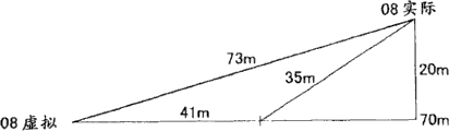
Center microphone CM8 is a cubical antenna, and it collects near the sound in edge of center circle, thus, has comprised long space and postpone when recording, and this delay must obtain the phase counter-bonification.
The virtual location of center microphone CM8 (virtual 08) is in the position at a distance of 41m with datum mark A.Yet,, be equal to by handle that described poor (that is, negative retardation 32m) is added to all sound channels except center microphone CM8, carries out compensation because the physical location of center microphone CM8 and virtual location be at a distance of 73m.
For example, though the distance from datum mark A to low microphone LM1 to LM7 is 92m, by adding opposite compensation rate, these distances are calculated as 124m, and thus, the decay of formula (3) calculated distance is shown will be 365ms by above.
In addition, under the situation of large-scale SPV, because the position of the more approaching actual sound source of microphone of back, from the range attenuation of the audio frequency of the loud speaker corresponding output with these microphones calculate and delay compensation actual be unnecessary, for low microphone LM1 to LM7, center microphone CM8 and middle microphone MM9 to MM12, by only deduct with from above calculated distance to corresponding volume of the distance of actual loudspeaker installation site and time of delay, can calculate from the volume and the time of delay of the audio frequency of loud speaker output.
The modification example of<2, first embodiment 〉
It should be appreciated by those skilled in the art that under the situation of the scope that does not break away from claim or its equivalent, can make various modification, combination, sub-portfolio and replacement according to the needs and the other factors of design.
<3, conclusion 〉
According to present embodiment, when watching capture video, listen to the audio frequency of collection, spectators can sense of reality take and the situation in the place of sound collecting to carrying out.
The application comprises the relevant theme of the disclosed theme of Japanese priority patent application JP 2009-100133 of submitting to Japan Patent office on April 16th, 2009, and its full content is contained in this for reference.
Claims (8)
1. video/audio input/output system comprises:
The video/audio input system comprises
Video input device is used for taking along specific direction with specific magnification ratio and obtains video, and the video that obtains is converted to the signal of telecommunication, and obtain electrical signal converted as vision signal, and
A plurality of voice input devices, be installed on aspect the horizontal range of the infield of video input device and height different a plurality of places, aspect, vibration around described a plurality of voice input device detects, the vibration that detects is converted to the signal of telecommunication, and obtain electrical signal converted as audio signal;
The video/audio output system comprises
The vision signal that video output device with display surface, described video output device obtain based on described video input device is at described display surface output video, and
A plurality of audio output devices, described a plurality of audio output devices correspond respectively to described a plurality of voice input device,
Wherein said a plurality of audio output device is installed in separately, according to described video with respect to the center that reduces ratio or magnification ratio and use described video of full-size(d) as benchmark, reduce or increase from the center of described video to from the installation site of corresponding voice input device to the distance of the intersection point of the drawn vertical line of described display surface and definite position, the audio signal that wherein said a plurality of audio output devices obtain based on corresponding voice input device and output audio.
2. the described video/audio input/output system of claim 1, wherein said a plurality of audio output devices are installed in the output that the allows described audio frequency direction towards the center of described video.
3. the described video/audio input/output system of claim 1, wherein the video/audio output system also comprises: output-controlling device, be used to make the corresponding time of distance between the installation site of the output time delay of audio frequency and specified place and described a plurality of voice input devices, and make corresponding a plurality of audio output device export described audio frequency.
4. the described video/audio input/output system of claim 1, wherein the video/audio output system also comprises: output-controlling device, the volume of audio frequency is diminished and the installation site of specified place and described a plurality of voice input devices between the corresponding volume down of distance in a small amount, and make corresponding a plurality of audio output device export described audio frequency.
5. the described video/audio input/output system of claim 3, wherein said specified place are the points that shows at the center of described video.
6. the described video/audio input/output system of claim 4, wherein said specified place are the points that shows at the center of described video.
7. the described video/audio input/output system of claim 1,
Wherein said video/audio input system also comprises input control device, the vision signal that the combination of described input control device is obtained by described video input device and each audio signal of being obtained by described a plurality of voice input devices are to produce audio/video signal, and an audio/video signal that produces is recorded in recording medium
Wherein said video/audio output system also comprises output-controlling device, described output-controlling device reading and recording is at the audio/video signal of recording medium, from the audio/video signal that reads, extract each audio signal and vision signal, the vision signal of extracting is exported to described video output device, simultaneously the audio signal output of each extraction is given and each the corresponding audio output device of each voice input device that obtains audio signal
Wherein said video output device is exported described video based on the vision signal of described output-controlling device output at described display surface,
Wherein said a plurality of audio output device is based on the described audio frequency of audio signal output of described output-controlling device output.
8. the described video/audio input/output system of claim 1,
Wherein said video/audio input system also comprises input control device, the vision signal that the combination of described input control device is obtained by described video input device and each audio signal of being obtained by described a plurality of voice input devices are to produce audio/video signal, and a video/audio signal that produces sends to described video/audio output system
Wherein said video/audio output system also comprises output-controlling device, described output-controlling device receives the audio/video signal that sends from described video/audio input system, from the audio/video signal that receives, extract each audio signal and vision signal, the vision signal of extracting is exported to described video output device, simultaneously the audio signal output of each extraction is given and each the corresponding audio output device of each voice input device that obtains audio signal
Wherein said video output device is exported described video based on the described vision signal of described output-controlling device output at described display surface,
Wherein said a plurality of audio output device is based on the described audio frequency of audio signal output of described output-controlling device output.
Applications Claiming Priority (2)
| Application Number | Priority Date | Filing Date | Title |
|---|---|---|---|
| JP2009-100133 | 2009-04-16 | ||
| JP2009100133A JP5369852B2 (en) | 2009-04-16 | 2009-04-16 | Video / audio input / output system |
Publications (1)
| Publication Number | Publication Date |
|---|---|
| CN101867864A true CN101867864A (en) | 2010-10-20 |
Family
ID=42959376
Family Applications (1)
| Application Number | Title | Priority Date | Filing Date |
|---|---|---|---|
| CN201010164252A Pending CN101867864A (en) | 2009-04-16 | 2010-04-09 | Video/audio input/output system |
Country Status (3)
| Country | Link |
|---|---|
| US (1) | US20100265399A1 (en) |
| JP (1) | JP5369852B2 (en) |
| CN (1) | CN101867864A (en) |
Cited By (1)
| Publication number | Priority date | Publication date | Assignee | Title |
|---|---|---|---|---|
| CN104898836A (en) * | 2015-05-19 | 2015-09-09 | 广东欧珀移动通信有限公司 | Rotatable camera adjustment method and user terminal |
Families Citing this family (4)
| Publication number | Priority date | Publication date | Assignee | Title |
|---|---|---|---|---|
| US9693009B2 (en) * | 2014-09-12 | 2017-06-27 | International Business Machines Corporation | Sound source selection for aural interest |
| US10447394B2 (en) * | 2017-09-15 | 2019-10-15 | Qualcomm Incorporated | Connection with remote internet of things (IoT) device based on field of view of camera |
| EP3470975B1 (en) * | 2017-10-10 | 2022-08-24 | Nokia Technologies Oy | An apparatus and associated methods for presentation of a bird's eye view |
| JP6664456B2 (en) * | 2018-09-20 | 2020-03-13 | キヤノン株式会社 | Information processing system, control method therefor, and computer program |
Citations (6)
| Publication number | Priority date | Publication date | Assignee | Title |
|---|---|---|---|---|
| US5335011A (en) * | 1993-01-12 | 1994-08-02 | Bell Communications Research, Inc. | Sound localization system for teleconferencing using self-steering microphone arrays |
| JP2003101981A (en) * | 2001-09-21 | 2003-04-04 | Hitachi Software Eng Co Ltd | Electronic cooperative work system and program for cooperative work system |
| CN1691765A (en) * | 2004-04-20 | 2005-11-02 | 索尼株式会社 | Information processing apparatus, imaging apparatus, information processing method, and program |
| WO2006054698A1 (en) * | 2004-11-19 | 2006-05-26 | Victor Company Of Japan, Limited | Video/audio recording apparatus and method, and video/audio reproducing apparatus and method |
| CN1929593A (en) * | 2005-09-07 | 2007-03-14 | 宝利通公司 | Spatially correlated audio in multipoint videoconferencing |
| CN2904500Y (en) * | 2006-06-01 | 2007-05-23 | 洪汉雄 | Video camera capable of photographing sound source position |
Family Cites Families (13)
| Publication number | Priority date | Publication date | Assignee | Title |
|---|---|---|---|---|
| JP3282202B2 (en) * | 1991-11-26 | 2002-05-13 | ソニー株式会社 | Recording device, reproducing device, recording method and reproducing method, and signal processing device |
| US6157403A (en) * | 1996-08-05 | 2000-12-05 | Kabushiki Kaisha Toshiba | Apparatus for detecting position of object capable of simultaneously detecting plural objects and detection method therefor |
| JPH11136656A (en) * | 1997-10-31 | 1999-05-21 | Nippon Telegr & Teleph Corp <Ntt> | Pickup sound wave transmission system and reception/ reproducing system adopting communication conference system |
| JPH11308591A (en) * | 1998-04-21 | 1999-11-05 | Fujitsu Ltd | Information communication system |
| US6469732B1 (en) * | 1998-11-06 | 2002-10-22 | Vtel Corporation | Acoustic source location using a microphone array |
| JP3584800B2 (en) * | 1999-08-17 | 2004-11-04 | ヤマハ株式会社 | Sound field reproduction method and apparatus |
| JP4734714B2 (en) * | 2000-12-22 | 2011-07-27 | ヤマハ株式会社 | Sound collection and reproduction method and apparatus |
| DE10305820B4 (en) * | 2003-02-12 | 2006-06-01 | Fraunhofer-Gesellschaft zur Förderung der angewandten Forschung e.V. | Apparatus and method for determining a playback position |
| JP4181511B2 (en) * | 2004-02-09 | 2008-11-19 | 日本放送協会 | Surround audio mixing device and surround audio mixing program |
| JP2006109295A (en) * | 2004-10-08 | 2006-04-20 | Sharp Corp | Audio playback apparatus, audio playback program, and program recording medium |
| US8237770B2 (en) * | 2004-10-15 | 2012-08-07 | Lifesize Communications, Inc. | Audio based on speaker position and/or conference location |
| US7995768B2 (en) * | 2005-01-27 | 2011-08-09 | Yamaha Corporation | Sound reinforcement system |
| US7733367B2 (en) * | 2006-02-21 | 2010-06-08 | Lynn Kenneth Packer | Method and system for audio/video capturing, streaming, recording and playback |
-
2009
- 2009-04-16 JP JP2009100133A patent/JP5369852B2/en not_active Expired - Fee Related
-
2010
- 2010-03-02 US US12/715,700 patent/US20100265399A1/en not_active Abandoned
- 2010-04-09 CN CN201010164252A patent/CN101867864A/en active Pending
Patent Citations (6)
| Publication number | Priority date | Publication date | Assignee | Title |
|---|---|---|---|---|
| US5335011A (en) * | 1993-01-12 | 1994-08-02 | Bell Communications Research, Inc. | Sound localization system for teleconferencing using self-steering microphone arrays |
| JP2003101981A (en) * | 2001-09-21 | 2003-04-04 | Hitachi Software Eng Co Ltd | Electronic cooperative work system and program for cooperative work system |
| CN1691765A (en) * | 2004-04-20 | 2005-11-02 | 索尼株式会社 | Information processing apparatus, imaging apparatus, information processing method, and program |
| WO2006054698A1 (en) * | 2004-11-19 | 2006-05-26 | Victor Company Of Japan, Limited | Video/audio recording apparatus and method, and video/audio reproducing apparatus and method |
| CN1929593A (en) * | 2005-09-07 | 2007-03-14 | 宝利通公司 | Spatially correlated audio in multipoint videoconferencing |
| CN2904500Y (en) * | 2006-06-01 | 2007-05-23 | 洪汉雄 | Video camera capable of photographing sound source position |
Cited By (4)
| Publication number | Priority date | Publication date | Assignee | Title |
|---|---|---|---|---|
| CN104898836A (en) * | 2015-05-19 | 2015-09-09 | 广东欧珀移动通信有限公司 | Rotatable camera adjustment method and user terminal |
| CN104898836B (en) * | 2015-05-19 | 2017-11-24 | 广东欧珀移动通信有限公司 | A kind of rotating camera adjusting method and user terminal |
| CN107885329A (en) * | 2015-05-19 | 2018-04-06 | 广东欧珀移动通信有限公司 | A kind of rotating camera adjusting method and user terminal |
| CN107885329B (en) * | 2015-05-19 | 2021-04-16 | Oppo广东移动通信有限公司 | Rotary camera adjusting method and user terminal |
Also Published As
| Publication number | Publication date |
|---|---|
| JP2010252102A (en) | 2010-11-04 |
| US20100265399A1 (en) | 2010-10-21 |
| JP5369852B2 (en) | 2013-12-18 |
Similar Documents
| Publication | Publication Date | Title |
|---|---|---|
| JP5992210B2 (en) | Information processing program, information processing apparatus, information processing system, and information processing method | |
| US11528576B2 (en) | Distributed audio capturing techniques for virtual reality (VR), augmented reality (AR), and mixed reality (MR) systems | |
| CN101742378B (en) | Positioning and reproducing screen sound source with high resolution | |
| CN205566613U (en) | Active intelligent thing networking audio amplifier | |
| KR20160005695A (en) | A Head Mounted Display and A Method for Providing Audio Contents Using the Same | |
| JPH01192299A (en) | Stereophonic sound collector | |
| CN101867864A (en) | Video/audio input/output system | |
| JPH06101875B2 (en) | Acoustic space reproducing method, acoustic recording device, and acoustic recording body | |
| CN105263093A (en) | Omnibearing audio acquisition apparatus, omnibearing audio editing apparatus, and omnibearing audio acquisition and editing system | |
| WO2015037905A1 (en) | Multi-viewer image and 3d stereophonic sound player system comprising stereophonic sound adjuster and method therefor | |
| CN103414992B (en) | A kind of message adjustment system | |
| JP5939444B2 (en) | Imaging device | |
| KR20140129654A (en) | A Head Mounted Display and A Method for Providing Audio Contents Using the Same | |
| JP2010252102A5 (en) | ||
| KR100962698B1 (en) | Audial and Visual Information Transfer System for Audience | |
| KR101747800B1 (en) | Apparatus for Generating of 3D Sound, and System for Generating of 3D Contents Using the Same | |
| CN206517613U (en) | It is a kind of based on motion-captured 3D audio systems | |
| CN208863060U (en) | Electroacoustics system for Multifunctional mobile arenas and the mobile cinema using canopy film | |
| CN202004950U (en) | Numerical control sound column based three-dimensional sound system | |
| JP5852325B2 (en) | Sound image localization improvement device | |
| CN109873933A (en) | Apparatus for processing multimedia data and method | |
| JP2020167471A (en) | Information processing apparatus, information processing method and program | |
| JP6274251B2 (en) | Image data generating apparatus and image data generating method | |
| KR102479067B1 (en) | Multi-channel sound system which provides a tracking sweet spot for visitors to the exhibition space | |
| KR102479068B1 (en) | Multi-channel sound system for each performer and multiple audiences in a small concert hall |
Legal Events
| Date | Code | Title | Description |
|---|---|---|---|
| C06 | Publication | ||
| PB01 | Publication | ||
| C10 | Entry into substantive examination | ||
| SE01 | Entry into force of request for substantive examination | ||
| AD01 | Patent right deemed abandoned |
Effective date of abandoning: 20151028 |
|
| C20 | Patent right or utility model deemed to be abandoned or is abandoned |