CN101840748B - Shielded cable - Google Patents
Shielded cable Download PDFInfo
- Publication number
- CN101840748B CN101840748B CN201010122090.3A CN201010122090A CN101840748B CN 101840748 B CN101840748 B CN 101840748B CN 201010122090 A CN201010122090 A CN 201010122090A CN 101840748 B CN101840748 B CN 101840748B
- Authority
- CN
- China
- Prior art keywords
- outer conductor
- antenna
- cable
- insulator
- antenna assembly
- Prior art date
- Legal status (The legal status is an assumption and is not a legal conclusion. Google has not performed a legal analysis and makes no representation as to the accuracy of the status listed.)
- Active
Links
Images


Classifications
-
- H—ELECTRICITY
- H01—ELECTRIC ELEMENTS
- H01B—CABLES; CONDUCTORS; INSULATORS; SELECTION OF MATERIALS FOR THEIR CONDUCTIVE, INSULATING OR DIELECTRIC PROPERTIES
- H01B11/00—Communication cables or conductors
- H01B11/18—Coaxial cables; Analogous cables having more than one inner conductor within a common outer conductor
- H01B11/20—Cables having a multiplicity of coaxial lines
- H01B11/206—Tri-conductor coaxial cables
-
- H—ELECTRICITY
- H01—ELECTRIC ELEMENTS
- H01Q—ANTENNAS, i.e. RADIO AERIALS
- H01Q9/00—Electrically-short antennas having dimensions not more than twice the operating wavelength and consisting of conductive active radiating elements
- H01Q9/04—Resonant antennas
- H01Q9/16—Resonant antennas with feed intermediate between the extremities of the antenna, e.g. centre-fed dipole
-
- H—ELECTRICITY
- H01—ELECTRIC ELEMENTS
- H01Q—ANTENNAS, i.e. RADIO AERIALS
- H01Q9/00—Electrically-short antennas having dimensions not more than twice the operating wavelength and consisting of conductive active radiating elements
- H01Q9/04—Resonant antennas
- H01Q9/30—Resonant antennas with feed to end of elongated active element, e.g. unipole
-
- H—ELECTRICITY
- H01—ELECTRIC ELEMENTS
- H01B—CABLES; CONDUCTORS; INSULATORS; SELECTION OF MATERIALS FOR THEIR CONDUCTIVE, INSULATING OR DIELECTRIC PROPERTIES
- H01B11/00—Communication cables or conductors
- H01B11/18—Coaxial cables; Analogous cables having more than one inner conductor within a common outer conductor
- H01B11/1808—Construction of the conductors
-
- H—ELECTRICITY
- H01—ELECTRIC ELEMENTS
- H01B—CABLES; CONDUCTORS; INSULATORS; SELECTION OF MATERIALS FOR THEIR CONDUCTIVE, INSULATING OR DIELECTRIC PROPERTIES
- H01B11/00—Communication cables or conductors
- H01B11/18—Coaxial cables; Analogous cables having more than one inner conductor within a common outer conductor
- H01B11/1878—Special measures in order to improve the flexibility
Abstract
A shielded cable includes an inner conductor, a first insulator, a first outer conductor, a second insulator, and a second outer conductor, which are coaxially disposed in this order from an inner side, and has an outer circumference coated by an insulation sheath. The shielded cable can realize a shielded antenna cable with low cost, excellent design and flexible performance.
Description
The cross reference of related application
The present invention comprises Japan's theme that formerly patent application JP2009-069089 is relevant of submitting to Japan Office on March 19th, 2009, and the full content of this application is incorporated to herein by reference.
technical field
The present invention relates to a kind of antenna assembly with flexibility being applicable to portable electron devices such as portable AV equipment and mobile phone.
background technology
In consumption electronic products field, the AV equipment of existence take portable acoustic reproduction device as representative etc., and also exist use coaxial cable by the situation of the sound of earphone (comprising headphone) listening equipment self.
In recent years, portable television receiver is also developed, and also has the situation of listening to its sound by earphone.Formed by shielded type cable for the cable of earphone, and also for transmitting the high-frequency signal of reception antenna etc.
Like this, just propose to utilize the technology of headphone cable as antenna.
Send audio signal (low-frequency band) with this cable, and for example in the case of the antenna for VHF and UHF, can exist because of the inapplicable situation of the lossy under high-frequency signal.
And, in the case of the common coaxial cable that is called 3C-2V or 5C-2V for high-frequency signal, although can make high-frequency transmission characteristic become fine by optimizing high-frequency design, problem is, thick, the heavy and flexibility of this cable or tensile property are low, and the very poor durability of movable part.
Therefore, applicant has proposed a kind of shielded type cable, and this cable can be used for the movable part as headphone cable and can transmit direct current signal (referring to No. 2006-164830, Japanese unexamined patent Publication).
Due to the main conductor that can use common annealed copper wire as shielded type cable, and can use general filament as strengthening filament, so can make cable with low cost.
And, by utilizing the filament of the low but material that hot strength is high of hardness as the enhancing filament of shielded type cable, can not reduce bendability by improving hot strength and flexibility prevents wire fracture, and can guarantee given electrical characteristics.
And, as a kind of example of antenna that uses coaxial cable, so-called sleeve antenna (for example, with reference to No. 2003-8333, Fig. 1 of No. 2003-249817, Japanese unexamined patent Publication and Japanese unexamined patent Publication Fig. 1) has been proposed.
The in the situation that of sleeve antenna, the structure of antenna is, signal is transmitted by coaxial cable and antenna element is located at the front end of coaxial cable.
It should be noted that especially the foldable structure of the ground wire GND that is called sleeve.
Sleeve antenna blocks by utilizing the foldable structure of sleeve to increase high-frequency resistance the electric current that the shell of cable carries.
But, in No. 2006-164830 disclosed antenna of Japanese unexamined patent Publication, due to the sleeve antenna in the situation that, in the time that antenna adapts to such as mobile phone etc., there is no foldable structure, thus need to by make the ground wire GND of equipment ground wire GND and coaxial cable play antenna GND be used for realizing resonance.
Thereby in this antenna, probably resonance frequency is along with the length variations of connected equipment ground wire GND will become problem.
And because equipment ground wire GND also contributes to the radiation of antenna, so for example controlling use mobile communication in the situation that by human body, because of equipment ground wire, GND is held, probably the gain meeting of antenna is influenced.
And in above-mentioned sleeve antenna, coaxial cable is only for signal transfer functions, and antenna part has very complicated structure.
Particularly, in the disclosed sleeve antenna of Japanese unexamined patent Publication No. 2003-249817 (Fig. 1), sleeve part comprises sheet metal, thereby flexibility and design are poor, and have that size is large, complexity and the higher shortcoming of cost.
Summary of the invention
The invention provides a kind of shielded type cable, this shielded type cable can be realized cost low and design and the fabulous screened shielded antanna cable of flexibility.
According to embodiments of the invention, a kind of shielded type cable is provided, it comprises the inner conductor, the first insulator, the first outer conductor, the second insulator and the second outer conductor that from inner side, coaxially arrange successively, and the periphery of described shielded type cable is insulated cover and covers, wherein, described inner conductor is insulated by described the first insulator, and comprises many first wires and filament, and each described first wire is insulated material and insulate.For example, described filament is formed in the part outside described many first wires by the hot strength attribute material higher than first wire, and described the first outer conductor and described the second outer conductor are formed by the braid shielded of the first wire braiding by many conductions.
According to embodiments of the invention, can realize cost low and design and the fabulous screened shielded antanna cable of flexibility.
accompanying drawing explanation
Figure 1A and Figure 1B are the first figure that represents the topology example of the shielded type cable of first embodiment of the invention;
Fig. 2 A and Fig. 2 B are the second figure that represents the topology example of the shielded type cable of first embodiment of the invention;
Fig. 3 is the first figure representing according to the ios dhcp sample configuration IOS DHCP of the inner conductor of embodiment;
Fig. 4 is the second figure representing according to the ios dhcp sample configuration IOS DHCP of the inner conductor of embodiment;
Fig. 5 is the figure representing according to the formation example of the braid shielded of embodiment;
Fig. 6 A and Fig. 6 B are the figure that represents the example of material, the external diameter etc. of each member of the shielded type cable of the first embodiment;
Fig. 7 A~Fig. 7 C is the figure that passes through loss measurement system that represents shielded type cable (coaxial cable);
Fig. 8 A~Fig. 8 D is the figure that passes through loss that represents inner conductor and the first outer conductor;
Fig. 9 A~Fig. 9 D is the figure that passes through loss that represents the first outer conductor and the second outer conductor;
Figure 10 A and Figure 10 B are the first figure that represents the topology example of the shielded type cable of second embodiment of the invention;
Figure 11 A and Figure 11 B are the second figure that represents the topology example of the shielded type cable of second embodiment of the invention;
Figure 12 A and Figure 12 B are the figure that the manufacture process of the shielded type cable shown in manufacture process and Figure 10 A and Figure 10 B of the shielded type cable shown in Figure 1A and Figure 1B contrasts each other;
Figure 13 A~Figure 13 C is the figure representing according to the ios dhcp sample configuration IOS DHCP of the antenna assembly of third embodiment of the invention;
Figure 14 A~Figure 14 C is the figure representing according to the ios dhcp sample configuration IOS DHCP of the antenna assembly of fourth embodiment of the invention;
Figure 15 is the figure representing according to another ios dhcp sample configuration IOS DHCP of the antenna assembly of fourth embodiment of the invention;
Figure 16 A~Figure 16 C is the figure representing according to the ios dhcp sample configuration IOS DHCP of the antenna assembly of fifth embodiment of the invention;
Figure 17 A and Figure 17 B are the figure that has represented to adopt the mobile phone of bar antenna;
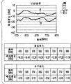
Figure 18 A and Figure 18 B are illustrated in the figure that adopts relation between the situation lower frequency of mobile phone closure of bar antenna and peak gain characteristic;
Figure 19 A and Figure 19 B are illustrated in the figure that adopts relation between situation lower frequency that the mobile phone of bar antenna opens and peak gain characteristic;
Figure 20 is the figure that is illustrated in an example of noise measurement system in the situation of bar antenna system;
Figure 21 A and Figure 21 B are the figure that is illustrated in noise testing result in the situation of bar antenna system;
Figure 22 is the figure that is illustrated in an example of noise measurement system in the situation of sleeve antenna system;
Figure 23 A and Figure 23 B are the figure that is illustrated in noise testing result in the situation of sleeve antenna system;
Figure 24 A and Figure 24 B are the figure that represents the mobile phone that adopts the sleeve antenna of not turning back;
Figure 25 A and Figure 25 B are the figure that represents the mobile phone relation between closed situation lower frequency and peak gain characteristic that adopts the sleeve antenna of not turning back;
Figure 26 A and Figure 26 B are the figure that is illustrated in relation between situation lower frequency that the mobile phone of the sleeve antenna that employing do not turn back opens and peak gain characteristic;
Figure 27 A and Figure 27 B are the figure that is illustrated in the function in the situation of front terminal shortcircuit of transmission line;
Figure 28 is the figure that is illustrated in sleeve part and is close to the problem existing in coaxial transmission cable situation;
Figure 29 A and Figure 29 B are when being illustrated in foldable structure and being formed by electric wire, and accordion cable does not have the figure of the problem in the situation of the enough distances in interval;
Figure 30 A and Figure 30 B are the figure that represents the mobile phone of the antenna assembly that there is no balanced-to-unblanced transformer that adopts the 3rd embodiment;
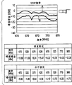
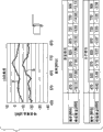
Figure 31 A and Figure 31 B are the figure that represents mobile phone relation between closed situation lower frequency and peak gain characteristic of the antenna assembly that there is no balanced-to-unblanced transformer that adopts the 3rd embodiment;
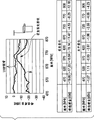
Figure 32 A and Figure 32 B are the figure that represents mobile phone relation between the situation lower frequency of opening and peak gain characteristic of the antenna assembly that there is no balanced-to-unblanced transformer that adopts the 3rd embodiment;
Figure 33 A and Figure 33 B are the figure that represents the mobile phone of the antenna assembly with balanced-to-unblanced transformer that adopts the 4th embodiment;
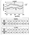
Figure 34 A and Figure 34 B are the figure that represents mobile phone relation between closed situation lower frequency and peak gain characteristic of the antenna assembly with balanced-to-unblanced transformer that adopts the 4th embodiment;
Figure 35 A and Figure 35 B are the figure that represents mobile phone relation between the situation lower frequency of opening and peak gain characteristic of the antenna assembly with balanced-to-unblanced transformer that adopts the 4th embodiment;
Figure 36 is the figure that has represented to adopt the mobile phone of the removed antenna assembly of a part of cable of the 5th embodiment;
Figure 37 is the figure that represents mobile phone relation between closed situation lower frequency and peak gain characteristic of the removed antenna assembly of a part of cable that adopts the 5th embodiment;
Figure 38 represents that dipole antenna device is configured to the not figure of the example of three core coaxial configurations of balance-imbalance converter;
Figure 39 is the figure that represents mobile phone relation between closed situation lower frequency and peak gain characteristic of the antenna assembly that adopts Figure 38;
Figure 40 represents that dipole antenna device is configured to the figure of the example of three core coaxial configurations of balance-imbalance converter;
Figure 41 is the figure that represents mobile phone relation between closed situation lower frequency and peak gain characteristic of the antenna assembly that adopts Figure 40;
Figure 42 is the figure that represents the variation example of the antenna assembly of Figure 40;
Figure 43 is the figure that represents mobile phone relation between closed situation lower frequency and peak gain characteristic of the antenna assembly that adopts Figure 42;
Figure 44 is the figure that represents the variation example of the antenna assembly of Figure 42;
Figure 45 is the figure that represents mobile phone relation between closed situation lower frequency and peak gain characteristic of the antenna assembly that adopts Figure 44;
Figure 46 is the figure of the example that changes from the state of Figure 44 of the length that represents substrate; And
Figure 47 is the figure that represents mobile phone relation between closed situation lower frequency and peak gain characteristic of the antenna assembly that adopts Figure 46.
Embodiment
Below, accompanying drawings various embodiments of the present invention.
And, describe in the following order:
1. the first embodiment (the first topology example of shielded type cable),
2. the second embodiment (the second topology example of shielded type cable),
3. the 3rd embodiment (the first ios dhcp sample configuration IOS DHCP of antenna assembly),
4. the 4th embodiment (the second ios dhcp sample configuration IOS DHCP of antenna assembly), and
5. the 5th embodiment (the 3rd ios dhcp sample configuration IOS DHCP of antenna assembly).
1. the first embodiment
Figure 1A, Figure 1B, Fig. 2 A and Fig. 2 B are the figure that represents the topology example of the shielded type cable of first embodiment of the invention.
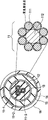
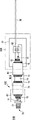
Figure 1A is the stereogram that represents shielded type cable each member under naked state of the first embodiment.Figure 1B is the drawing in side sectional elevation of the simplification of the shielded type cable of the first embodiment.
Fig. 2 A is the drawing in side sectional elevation of the simplification of the shielded type cable of the first embodiment, and Fig. 2 B is the end view that represents shielded type cable each member under naked state of the first embodiment.
The shielded type cable 10 of the present embodiment is formed as coaxial and double layer screen cable.In other words, the shielded type cable 10 of the present embodiment has the double-layer coaxial construction of cable.
[configuration of double layer screen cable]
Shielded type cable 10 comprises from inner side coaxial inner conductor (sometimes also referred to as center conductor) 11, the first insulator 12, the first outer conductor 13, the second insulator 14 and the second outer conductor 15 arranging successively, and shielded type cable 10 is placed outside and is insulated cover 16 and covers.
That is, in shielded type cable 10, inner conductor 11 is insulated by the first insulator 12, and the first outer conductor 13 is located at coaxially the first the outer of insulator 12 and is placed.And in shielded type cable 10, the first outer conductor 13 is insulated by the second insulator 14, and the second outer conductor 15 is located at coaxially the second the outer of insulator 14 and is placed.
Afterwards, the whole periphery of shielded type cable 10 is insulated cover 16 coverings.
In the example shown in Figure 1A, Figure 1B, Fig. 2 A and Fig. 2 B, inner conductor 11 is made up of three wire 11-1,11-2 and 11-3.
Fig. 3 and Fig. 4 are the figure that represents the ios dhcp sample configuration IOS DHCP of the inner conductor of the present embodiment.
As shown in Figure 3 and Figure 4, each wire of inner conductor 11 comprises many first wires 111 and filament 112, and this filament 112 is formed in many parts outside first wire 111 by the hot strength attribute material higher than first wire.
In inner conductor 11, be provided with the many wires that are for example coated with polyurethane, and by for example having by aramid fiber (aramid fiber) etc. that core that the filament 112 forming compared with the material of high tensile attribute is located at wire stretches with reply and bending.
In the example of Fig. 4, many polyurethane wires are bundled in also coated together.Like this, can prevent that many polyurethane wires from scattering.The core of polyurethane wire is for example made up of copper cash.
Polyurethane coating forms like this, and for example wire 11-1 is red, and wire 11-2 is green, and wire 11-3 is transparent.
Many strips that these wires are for example set to L, R and G as inner conductor are for audio signal transmission.
Like this, multiple inner conductor 11-1,11-2 and 11-3 for example, are insulated by insulator (polyurethane) separately, thereby these inner conductors can transmit multiple signals with direct current form.
And, by distortion spirally and the multiple inner conductors of layout, with regard to high frequency, bonding them together thus, these inner conductors can be counted as a conductor at upper frequency place.
And, as mentioned above, can use the aramid fiber with high tensile attribute and excellent heat resistance as filament 112.Because aramid fiber also can be as the fortifying fibre of inner conductor 11, so can realize sharing of material therefor.
In addition, for example can use commercial fiber such as Kevlar (Kevlar) (registered trade mark of Du Pont (DuPont)) or special fertile synthetic fibre (Twaron) (Supreme Being people's (Teijin) registered trade mark) as aramid fiber.
The first insulator 12 makes the first outer conductor 13 insulate with inner conductor 11.
Can use such as vinyl chloride (vinyl chloride), polyethylene (PE) or polyacrylic thermoplastic resin as the first insulator 12.
Preferably use the crosslinked foaming polyethylene that there is fabulous electrical characteristics and stable on heating tetrafluoroethene and perfluoroalkyl vinyl ether copolymer (tetrafluoroethylene perfluoroalkyl vinyl ether copolymer, PFA) or there is low-k or dielectric loss as the first insulator 12.
The first outer conductor 13 is around the periphery of the first insulator 12, and the characteristic impedance that the dielectric constant of the first insulator 12 is adjusted to the coaxial configuration that makes inner conductor 11 and the first outer conductor 13 becomes 50 Ω or 75 Ω.
The second insulator 14 insulate the second outer conductor 15 and the first outer conductor 13.
Be similar to the first insulator 12, preferably use the crosslinked foaming polyethylene that there is fabulous electrical characteristics and stable on heating tetrafluoroethene and perfluoroalkyl vinyl ether copolymer (tetrafluoroethylene perfluoroalkyl vinylether copolymer, PFA) or there is low-k or dielectric loss as the second insulator 14.
The second outer conductor 15 is around the periphery of the second insulator 14, and the characteristic impedance that the dielectric constant of the second insulator 14 is adjusted to the coaxial configuration that makes the first outer conductor 13 and the second outer conductor 15 becomes 50 Ω or 75 Ω.
As mentioned above, preferably, the first insulator 12 and the second insulator 14 are made by have low-loss material with regard to high frequency such as polyethylene or polyethylene foamed etc.
In the present embodiment, the first outer conductor 13 and the second outer conductor 15 are formed by braid shielded, and this braid shielded is formed by many conductivity unit wire braidings, for example, formed by many exposed annealed copper wire braidings.
In addition, compared with servo shielding, in braid shielded, shielding intermediate gap be formed on bending time also very little, and be known that braid shielded is a kind of electrostatic screen method with suitable flexibility, bending strength and mechanical strength.
Fig. 5 is the figure that represents the formation example of the braid shielded of the present embodiment.
In braid shielded 20, conventionally, several first wires 21 are as one group, and the number of group is called " beating number ", and the number of a first wire hitting is expressed as " number of share of stock ", and the sum of first wire is corresponding to " number of share of stock " × " beating number ".
In the braid shielded of ultra-fine shielded type cable, conventionally, number of share of stock is 2~10 first wires, beats number and is made as 10~30 groups.In the present embodiment, the part having outside first wire 21 of braid shielded of this configuration is made up of the filament 22 having compared with high tensile attribute material.
In the case, for example, if number of share of stock is 4, except first wire 21 is replaced by filament 22, thereby braid shielded 20 overall 1/4 is filament 22.
In addition, can use than forming first wire 21 of braid shielded 20 and there is more any plain conductor of high tensile attribute and the material of nonmetal wire as filament 22.
And, in the situation that for example using alloy wire as filament 22, coating with satisfactory electrical conductivity etc. is deposited on metal wire to guarantee that shielding character is also feasible.
And, be used as filament 22 at the non-metal wire such as high tensile strength fiber, same feasible, for example use the metallic fiber forming by coated copper on the surface of high tensile strength fiber etc. or the copper foil wire forming around the long Copper Foil band of high tensile strength fiber silk winding rectangle as filament.
And, in the situation that insulating case 16 passes through the molded formation of extruder, owing to relating to heating, there is stable on heating filament as filament 22 so use.
Like this, in the first embodiment, utilize the thread shielding of exposed soft copper to be formed at around the first insulator 12 and the second insulator 14.
As mentioned above, this shielding has the structure being woven into by exposed annealed copper wire.By braiding, further promote the coupling aspect high frequency between conductor, even and if these conductor weave ins, also can regard a conductor as, thereby can further reduce high-frequency loss.
The in the situation that of servo shielding, shielding properties inevitable with winding department apart from variation, and along with the increase of coiling quantity, shielding properties improves, and flexibility worsens.
By interweaving, obtain such structure, although gap is added, flexibility is influenced hardly.
For example by extruder, the resins such as styrenic elastomer are carried out to mold pressing, thereby form insulating case 16 (sometimes also referred to as outer cover or shell).
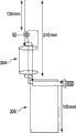
Fig. 6 A and Fig. 6 B are the figure that represents the example of material, the external diameter etc. of each member of the shielded type cable of the first embodiment.
Fig. 6 A is the form that represents material, the external diameter etc. of each member of shielded type cable.
Fig. 6 B is the figure that represents the size of the external diameter of each member of shielded type cable.
In Fig. 6 A and 6B, the external diameter Φ of inner conductor 11 is made as 0.25mm.
The external diameter Φ of the first insulator 12 is made as 0.61mm.
In the case, the thickness of the first insulator 12 is about 0.36mm.The standard thickness of the first insulator 12 is 0.14mm.
The external diameter Φ of the first outer conductor 13 is made as 0.89mm.
In the case, the thickness of the first outer conductor 13 is about 0.28mm.
The external diameter Φ of the second insulator 14 is made as 2.0mm.
In the case, the thickness of the second insulator 14 is about 1.11mm.The standard thickness of the second insulator 14 is 0.56mm.
The external diameter Φ of the second outer conductor 15 is made as about 2.27mm.
In the case, the thickness of the second outer conductor 15 is 0.27mm.
The external diameter Φ of insulating case 16 is made as about 2.6mm.
In the case, the thickness of insulating case 16 is 0.33mm.The standard thickness of insulating case 16 is 0.17mm.
Below, consider the shielded type cable structure relevant to high-frequency resistance of the shielded type cable 10 of the first embodiment.
Fig. 7 A~Fig. 7 C is the figure that passes through loss measurement system that represents shielded type cable (coaxial cable).
Fig. 7 A is the figure representing by the object of loss measurement.
Fig. 7 B is the figure that represents the equivalent electric circuit that passes through loss measurement system of inner conductor and the first outer conductor (braid shielded 1).
Fig. 7 C is the figure that represents the equivalent electric circuit that passes through loss measurement system of the first outer conductor (braid shielded 1) and the second outer conductor (braid shielded 2).
Fig. 8 A~Fig. 8 D is the figure that passes through loss that represents inner conductor and the first outer conductor.
Fig. 9 A~Fig. 9 D is the figure that passes through loss that represents the first outer conductor and the second outer conductor.
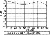
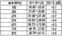
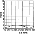
In these figure, inner conductor 11 is called as center conductor, and the first outer conductor 13 is called as coaxial braiding A, and the second outer conductor 15 is called as coaxial braiding B.
Conductor structure is determined according to the high-frequency resistance between the inner conductor 11 at center and the first insulator 12.
Here,, as the example of Fig. 7 B and Fig. 8 A~Fig. 8 D so designs, the impedance between inner (center) conductor 11 and the first outer conductor (braid shielded 1 coaxially weaves A) 13 is 50 Ω.
Measure the loss of passing through of the long coaxial cable of 100mm.
Diameter of phi at inner (center) conductor 11 is about 0.6mm, and the poly dielectric constant of the first insulator 12 is in the situation of 2 (ε r=2), by making the first outer conductor (braid shielded 1, coaxial braiding A) diameter be about 0.9mm, can obtain the high-frequency resistance of 50 Ω.
In addition, can reduce dielectric constant, reduce wavelength decreases effect and reduce dielectric loss by utilizing polyethylene foamed to form the first insulator 12.
And, can improve the pliability of insulator, thereby improve flexibility.
Afterwards, the second insulator 14 is located at the first outer conductor (braid shielded 1) around.
Then, the second outer conductor (braid shielded 2) 15 is located at around the second insulator 14.
With respect to the second outer conductor (braid shielded 2, coaxial braiding B), the first outer conductor (braid shielded 1) 13 and the second outer conductor (braid shielded 2) 15 in the situation that, as shown in Fig. 7 C, can think coaxial configuration considering two conductors.
As shown in Fig. 7 C, by regarding the first outer conductor (braid shielded 1) 13 as center conductor, and the second outer conductor (braid shielded 2) 15 is configured to the shielded conductor for this center conductor, can form coaxial transmission line.
In the case, as shown in Fig. 9 A~Fig. 9 D, in the time that the diameter of center conductor (braid shielded 1) is made as Φ 0.9mm, by utilizing dielectric (the second insulator 14) to make shielding for Φ 2.3mm, can obtain the effect of the coaxial cable of the characteristic impedance with about 50 Ω.
Finally, by, having made cable around using be arranged in the second outer conductor (braid shielded 2) as the shell of being made by elastomer of insulator.
As mentioned above, the shielded type cable 10 of the present embodiment comprises the inner conductor 11, the first insulator 12, the first outer conductor 13, the second insulator 14 and the second outer conductor 15 that from inner side, coaxially arrange successively, and shielded type cable 10 is insulated cover 16 coverings at periphery place.
The first outer conductor 13 and the second outer conductor 15 are formed by braid shielded, and this shielding is woven by many conductive element wires.
Therefore,, according to the shielded type cable of the present embodiment, can obtain following effect.
, can make with low cost the shielded type cable of the present embodiment.
And this shielded type cable can be realized improve (simplification of the bending of cable and stretching and structure) of the improvement of design performance and flexibility.
And the shielded type cable of the present embodiment can realize that price is low, design performance and the fabulous screened shielded antanna cable of flexibility, and can realize the improvement of high frequency characteristics.
In addition,, will describe the shielded type cable of the present embodiment in detail as the situation of screened shielded antanna cable.
2. the second embodiment
Figure 10 A, Figure 10 B, Figure 11 A and Figure 11 B are the figure that represents the topology example of the shielded type cable of second embodiment of the invention.
Figure 10 A is the stereogram that represents shielded type cable each member under naked state of the second embodiment.Figure 10 B is the drawing in side sectional elevation of the simplification of the shielded type cable of the second embodiment.
Figure 11 A is the drawing in side sectional elevation of the simplification of the shielded type cable of the second embodiment.Figure 11 B is the end view that represents shielded type cable each member under naked state of the second embodiment.
Difference between the shielded type cable 10A of the second embodiment and the shielded type cable 10 of the first embodiment is as follows:
The couple state that, the shielded type cable 10A of the second embodiment is configured to the second insulator 14 and the first outer conductor 13 equals or is coarser than the couple state of the second insulator 14 and the second outer conductor 15.
In the shielded type cable 10A shown in Figure 10 A, Figure 10 B, Figure 11 A and Figure 11 B, diaphragm seal 17 is located between the second insulator 14 and the first outer conductor 13.
The reason that diaphragm seal 17 is set between the second insulator 14 and the first outer conductor 13 is as follows:
Shielded type cable 10 shown in Figure 1A, Figure 1B, Fig. 2 A and Fig. 2 B can be realized double-layer shielding structure by inner conductor 11, the first insulator 12, the first outer conductor 13, the second insulator 14 and the second outer conductor 15 are set coaxially, and identical with shown in Figure 12 A of its manufacture process.
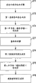
First step ST1 is the step of distortion inner conductor 11.
Second step ST2 is the extrusion molding step of the first insulator 12.
The 3rd step ST3 is the step of the first outer conductor (braid shielded) 13 of interweaving.
The 4th step ST4 is the extrusion molding step of the second insulator 14.
The 5th step ST5 is the step of the second outer conductor (braid shielded) 15 of interweaving.
The 6th step ST6 is the extrusion molding step of insulating case 16.
In above-mentioned manufacture process, in the 4th step ST4, in the time that rising to approximately 250 ℃, temperature carries out the extrusion molding step of the second insulator 14.
As mentioned above, in the situation that the second insulator 14 is made up of polyethylene, probably there will be following problem:
; because the fusing point of polyethylene (PE) is 110 ℃; so the second insulator 14 by extrusion molding around the first outer conductor (braid shielded 1) 13 form in the situation that; there will be the resin of thawing to infiltrate the situation about interweaving in part weaving, thereby adhesion strength excessively increase.
Occurring when this situation, for example, become difficulty for the extraction work of electric wire of the end processing (soldering) of carrying out braid shielded.
Therefore, in a second embodiment, as shown in Figure 12 B, after the first outer conductor (braid shielded) 13 that interweaves of the 3rd step ST3, be arranged on the step that is wound around diaphragm seal on the first outer conductor (braid shielded 1) 13 as the 7th step ST7.
Afterwards, carry out the step of the extrusion molding of the second insulator 14 of the 4th step ST4.
Like this, infiltrate in braiding to prevent resin by be wound around diaphragm seal 17 on the first outer conductor (braid shielded 1) 13, sealing film plays and prevents that resin from flowing into the effect in braid shielded, thereby end processing becomes easy.
By be wound around diaphragm seal 17 on the first outer conductor (braid shielded 1) 13, can prevent reliably that resin from flowing in braid shielded.
But, and the nonessential diaphragm seal 17 that arranges.
For example, be that the PET of 264 ℃ is as the second insulator 14, in the extrusion molding of the second insulator 14 of the 4th step ST4, even if the second insulator 14 also can not melt in the time that temperature rises to approximately 250 ℃ at fusing point.
And, even by use polyethylene during as the first insulator 12 resin flow to the first outer conductor 13, even and utilize PET to prevent flowing of resin, also very little on the impact of end processing.
In the case, even if diaphragm seal 17 is not set, also can carry out such configuration, the couple state of the second insulator 14 and the first outer conductor 13 equals or is coarser than the couple state of the second insulator 14 and the second outer conductor 15.
According to the second embodiment, except the above-mentioned effect of the first embodiment, can prevent that resin from flowing in braid shielded, thereby advantage is end, processing becomes easier.
The ios dhcp sample configuration IOS DHCP of the antenna assembly that has adopted the shielded type cable 10 of the first embodiment and the shielded type cable 10A of the second embodiment is described below., consider the characteristic of antenna assembly of the shielded type cable that adopts the present embodiment below, comprising with the comparison of common bar antenna, dipole antenna etc.
First, adopted three ios dhcp sample configuration IOS DHCPs of the antenna assembly of the shielded type cable 10 of the first embodiment and the shielded type cable 10A of the second embodiment to describe as the 3rd embodiment, the 4th embodiment and the 5th embodiment respectively.
3. the 3rd embodiment
Figure 13 A~Figure 13 C is the figure that represents the ios dhcp sample configuration IOS DHCP of the antenna assembly of third embodiment of the invention.
Figure 13 A is the figure that represents the structural principle of the antenna assembly of the 3rd embodiment.
Figure 13 B is the figure that represents the equivalent electric circuit of the antenna assembly of the 3rd embodiment.
Figure 13 C is the figure that represents the concrete configuration example of the antenna assembly of the 3rd embodiment.
In antenna assembly 30, substantially, the shielded type cable 10 of the first embodiment and the shielded type cable 10A of the second embodiment are as the screened shielded antanna cable 10B of antenna.
Thereby in the screened shielded antanna cable 10B shown in Figure 13 A~Figure 13 C, the part identical with 10A with shielded type cable 10 represents with identical Reference numeral.
In antenna assembly 30, screened shielded antanna cable 10B has the first connecting portion 40 and has the second connecting portion 50 in the other end an end.
And antenna assembly 30 has antenna element 60, this antenna element 60 is connected with the other end of screened shielded antanna cable 10B by the second connecting portion 50.
Screened shielded antanna cable 10B is the cable being connected with electronic installation, and the entirety of screened shielded antanna cable 10B or a part of antenna that receives radio or television signal that is used as.
And, as mentioned above, screened shielded antanna cable 10B comprises the inner conductor 11, the first insulator 12, the first outer conductor 13, the second insulator 14 and the second outer conductor 15 that from inner side, coaxially arrange successively, and screened shielded antanna cable 10B is insulated cover 16 coverings at periphery place.
That is, in shielded type cable 10, inner conductor 11 is insulated by the first insulator 12, and the first outer conductor 13 is located at coaxially the first the outer of insulator 12 and is placed.And in shielded type cable 10, the first outer conductor 13 is insulated by the second insulator 14, and the second outer conductor 15 is located at the second the outer of insulator 14 and is placed.
In shielded type cable 10, its whole periphery is insulated cover 16 and covers.
So, inner conductor 11 and the first outer conductor 13 and the first outer conductor 13 and the second outer conductor 15 have high-frequency resistance.
The first connecting portion 40 is formed as connector, and its one end at screened shielded antanna cable 10B is connected with the terminal 71 of the receiver (tuner) 70 of electronic installation.
The first connecting portion 40 is formed as, and for example, in the time that this connecting portion is connected with the terminal 71 of receiver 70, inner conductor 11 is powered and the first outer conductor 13 is connected with the ground wire GND of receiver 70.
; in the example shown in Figure 13 A~Figure 13 C; in the first connecting portion 40; inner conductor 11 is connected with the power supply circuits of the receiver 70 of electronic installation; and the first outer conductor 13 of cable is connected with the ground wire GND of receiver 70, thereby screened shielded antanna cable 10B plays the effect of unbalanced transmission path.
The second connecting portion 50 has connection substrate (printed base plate) 51, and the other end of screened shielded antanna cable 10B is connected with antenna element 60.
In the second connecting portion 50, the first outer conductor 13 of screened shielded antanna cable 10B is connected with antenna element 60, and inner conductor 11 is connected with the second outer conductor 15.
The first connecting portion 40 and the second connecting portion 50 form by mold pressing, or form as housing.
As mentioned above, antenna assembly 30 is designed to, and with respect to double layer screen cable 10B, transmission line is formed between inner conductor 11 and the first outer conductor 13, and impedance is for example 50 Ω.
And coaxial configuration is formed between the first outer conductor 13 and the second outer conductor 15 of double layer screen cable 10B similarly.
By regulating the length between the first outer conductor 13 and the second outer conductor 15, can easily control the impedance of coaxial cable.
So, by utilizing the coaxial configuration of the present embodiment, can be configured to utilize the high frequency trap of coaxial cable.
As hereinafter described in detail, according to the 3rd embodiment, because the shielded type cable 10 of the first embodiment and the 10A of the second embodiment are as the screened shielded antanna cable 10B of antenna, so can be configured to the antenna assembly that not affected by equipment side.
And only by the end processing of cable, with regard to configurable sleeve part, thereby sleeve part can be configured to and do not use sheet metal, or ferrule element is as parts independently.Thereby, can be very simple and qurer configuration sleeve part, and only according to the rugosity peace weighlock of cable every design sleeve part.
And owing to will not becoming the T shape as dipole antenna by dwi hastasana, so the configuration of element also becomes simply, and antenna can be used as linear antenna.
4. the 4th embodiment
Figure 14 A~Figure 14 C is the figure that represents the ios dhcp sample configuration IOS DHCP of the antenna assembly of fourth embodiment of the invention.
Figure 14 A is the figure that represents the structural principle of the antenna assembly of the 4th embodiment.
Figure 14 B is the figure that represents the equivalent electric circuit of the antenna assembly of the 4th embodiment.
Figure 14 C is the figure that represents the concrete configuration example of the antenna assembly of the 4th embodiment.
The difference of the antenna assembly 30 of the antenna assembly 30A of the 4th embodiment and the 3rd above-mentioned embodiment is the second connecting portion 50A, and the other end of screened shielded antanna cable 10B is connected with antenna element 60 by balanced-to-unblanced transformer (balun) 52.
Particularly, the inner conductor 11 of screened shielded antanna cable 10B is connected with balanced-to-unblanced transformer 52 with the first outer conductor 13.
One end of balanced-to-unblanced transformer 52 is connected with the second outer conductor 15 of screened shielded antanna cable 10B, and the other end of balanced-to-unblanced transformer 52 is connected with antenna element 60.
The first outer conductor 13 is connected with antenna element 60 by balanced-to-unblanced transformer 52, and inner conductor 11 is connected with the second outer conductor 15 by balanced-to-unblanced transformer 52.
Balanced-to-unblanced transformer 52 is arranged on printed base plate (connection substrate) 51, and cable is connected with the plane of printed base plate 51, thereby can complete the wiring as antenna assembly.Like this, this mounting structure is very simple.
In addition, balun device is not limited to 1: 1 structure, and for example 1: 4 structure is also fine.
As hereinafter described in detail, according to the 4th embodiment, owing to also having adopted balanced-to-unblanced transformer 52 except the configuration of the 3rd embodiment, so can be configured to the antenna assembly that not further affected by equipment side.
In addition, as shown in figure 15, also can between balanced-to-unblanced transformer 52 and inner conductor 11, amplifier 53 be set.
In the case, a terminal of the balanced-to-unblanced transformer 52 being connected with antenna element 60 is connected with the input of amplifier 53, and the output of amplifier 53 is connected with inner conductor 11.
And the first outer conductor 13 is connected with ground wire GND.
One end of the another terminal of balanced-to-unblanced transformer 52 is connected with ground wire GND, and the other end is connected with the second outer conductor 15.
Like this, by amplifier 53 is set, can realize the improvement of receiver sensitivity.
5. the 5th embodiment
Figure 16 A~Figure 16 C is the figure that represents the ios dhcp sample configuration IOS DHCP of the antenna assembly of fifth embodiment of the invention.
Figure 16 A is the figure that represents the structural principle of the antenna assembly of the 5th embodiment.
Figure 16 B is the figure that represents the equivalent electric circuit of the antenna assembly of the 5th embodiment.
Figure 16 C is the figure that represents the concrete configuration example of the antenna assembly of the 5th embodiment.
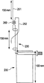
The difference of the antenna assembly 30A of the antenna assembly 30B of the 5th embodiment and above-mentioned the 4th embodiment is, at it, the part place on longitudinally has removal portion 80 to screened shielded antanna cable 10C, and in this removal portion 80, insulating case 16 and the second outer conductor 15 are removed.
Here, screened shielded antanna cable 10C longitudinally on part be and the other end of cable at a distance of the position of (n λ)/2, wherein λ is wavelength.
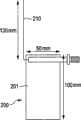
In Figure 16 A~Figure 16 C, antenna element 60 is (1/4) λ, and removal portion 80 is formed at and the position at a distance of (1/4) λ, the other end of balanced-to-unblanced transformer 52.
Particularly, removal portion 80 is formed at and the position of the other end at a distance of 160mm.
According to the 5th embodiment, including the effect of the 4th embodiment, can also regulate the frequency of antenna assembly.
[characteristic of antenna assembly]
Below, consider the characteristic etc. of the antenna assembly of the shielded type cable that has adopted the present embodiment, comprising with the comparison of common bar antenna, dipole antenna etc.
First, feature when Comparatively speaking the shielded type cable of the present embodiment is used for antenna assembly with bar antenna etc. is described.
Figure 17 A and Figure 17 B are the figure that represents the mobile phone that adopts bar antenna.
Figure 17 A shows the main body of the mobile phone situation when closed, the situation when main body that Figure 17 B shows mobile phone is opened.
Example shown in Figure 17 A and Figure 17 B is the example that uses the bar antenna 210 of 130mm.
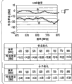
Figure 18 A and Figure 18 B are the figure of relation between frequency and peak gain characteristic while representing to adopt the mobile phone of bar antenna closed.Figure 18 A shows the characteristic of free space, characteristic when Figure 18 B shows mobile phone and is placed on human body.
Figure 19 A and Figure 19 B are the figure of relation between frequency and peak gain characteristic while representing to adopt the mobile phone of bar antenna to open.Figure 19 A shows the characteristic of free space, characteristic when Figure 19 B shows mobile phone and is placed on human body.
In Figure 18 A, Figure 18 B, Figure 19 A and Figure 19 B, shown the characteristic of horizontal polarization by " A " represented curve, shown the characteristic of perpendicular polarization by " B " represented curve.
The antenna using in mobile phone etc. is the antenna of 1/4 monopolar DC system take the bar antenna 210 shown in Figure 17 A and Figure 17 B as representative.
This antenna is to be used as by utilizing bar antenna and equipment ground wire GND to carry out the antenna of resonance.The in the situation that of bar antenna 210, bandwidth and gain are fabulous, thereby no problem.
But the in the situation that of this example, as shown in Figure 18 A, Figure 18 B, Figure 19 A and Figure 19 B, while supposing to be mobile phone 200, antenna has the size applicable for the resonance frequency of UHF bandwidth, from but optimum.But, because the ground wire GND of equipment is used as antenna, so also exist characteristic to be subject to the problem of the size impact of the ground wire GND of equipment.
And, in the case of the noise of equipment is large, there is the problem worsening due to the sensitivity due to the reception of autoradiolysis noise.
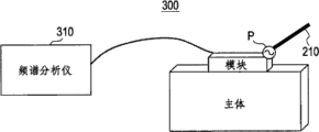
Figure 20 is the figure that is illustrated in an example of noise measurement system in the situation of bar antenna system.
Figure 21 A and Figure 21 B are the figure that represents noise testing result in the situation that of bar antenna system.Noise testing result when Figure 21 A shows shutdown, noise testing result when Figure 21 B shows start.
As shown in Figure 21 A and Figure 21 B, the in the situation that of bar antenna system, receiver is by antenna reception autoradiolysis noise.
If carry out noise of equipment measurement and optimized device ground wire GND, bar antenna is good antenna.But, can find, this antenna is also the antenna that must carry out equipment side measurement.
On the contrary, as the antenna of impact that reduces as much as possible equipment, there is sleeve antenna.
The in the situation that of sleeve antenna, by utilizing concentric conductor to make the supply terminals P of antenna not contact main body, can realize the structure of noise of equipment source away from antenna, thereby can improve receptivity by the improvement of C/N.
Figure 22 is the figure that is illustrated in an example of noise measurement system in the situation of sleeve antenna system.
Figure 23 A and Figure 23 B are the figure that is illustrated in noise testing result in the situation of sleeve antenna system.Noise testing result when Figure 23 A shows shutdown, noise testing result when Figure 23 B shows start.
Can find out from Figure 23 A and Figure 23 B, compared with common bar antenna, by adopting sleeve antenna 230, noise can improve 7dB.
As described in the background section, the in the situation that of sleeve antenna, antenna has by the structure of coaxial cable signal transmission, and antenna is located at the front end place of coaxial cable.It should be noted that especially the foldable structure of the ground wire GND that is called sleeve.
This has blocked the contained electric current of shell of cable by utilizing the foldable structure of sleeve to increase high-frequency resistance.This tube-in-tube structure makes device complexity, causes thus cost to increase.
Figure 24 A and Figure 24 B are the figure that represents the mobile phone that adopts the sleeve antenna of not turning back.Figure 24 A shows the main body of the mobile phone situation when closed, the situation when main body that Figure 24 B shows mobile phone is opened.
Example shown in Figure 24 A and Figure 24 B is the example that uses the 3 core coaxial sleeve antennas 230 of the 150mm not turning back.
Figure 25 A and Figure 25 B are the figure that is illustrated in relation between the situation lower frequency of mobile phone closure of the sleeve antenna that employing do not turn back and peak gain characteristic.Figure 25 A shows the characteristic of free space, characteristic when Figure 25 B shows mobile phone and is placed on human body.
Figure 26 A and Figure 26 B are the figure that is illustrated in relation between situation lower frequency that the mobile phone of the sleeve antenna that employing do not turn back opens and peak gain characteristic.Figure 26 A shows the characteristic of free space, characteristic when Figure 26 B shows mobile phone and is placed on human body.
In Figure 25 A, Figure 25 B, Figure 26 A and Figure 26 B, represented the characteristic of horizontal polarization by " A " represented curve, shown the characteristic of perpendicular polarization by " B " represented curve.
This example shows the structure that antenna is drawn out of by coaxial cable, and thus away from receiver, and in this example, antenna is suitable for situation optimum in UHF bandwidth.
The in the situation that of sleeve antenna 230, owing to there is no foldable structure, by make the ground wire GND of equipment ground wire GND and coaxial cable play antenna ground wire GND be used for carrying out resonance.
Thereby problem is that resonance frequency is according to the length variations of connected equipment ground wire GND.And because receiver ground wire GND also contributes to the radiation of antenna, so for example controlling use mobile communication in the situation that by human body, because of receiver ground wire, GND is held, and can have the affected problem of gain of antenna.
In order to reduce the impact of cable and equipment ground wire GND, reduce the noise from equipment simultaneously, folding ground wire GND must be set.
Although can provide various foldable structures, all structures all size are large, complicated and be difficult to realize and be difficult to popular with low cost.
This is relevant with the function of sleeve.
In the time of configuration sleeve antenna, need between concentric conductor and sleeve part, reserve certain distance.
This is that characteristic impedance is relevant with signal transmission distance because in signal transmission path.
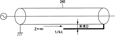
And this is because as shown in Figure 27 A and Figure 27 B, in the case of the front terminal shortcircuit of transmission line 240, impedance becomes infinitely great ∞ at 1/4 λ place of the transmission range apart from port PT1, thereby plays the effect of the trap of blocking-up electric current.But, the in the situation that of forming folding part in the time fully not completely cutting off with regard to high frequency, not this means and do not work.
As shown in figure 28, high-frequency coupling occurs at sleeve part near coaxial transmission cable in the situation that, thereby this part does not play the effect of foldable structure.
Thereby, in the case of the foldable structure as shown in Figure 29 A and Figure 29 B is formed by electric wire, when in accordion cable, do not reserve enough apart from time, think and can produce and the coupling of transmission line, thereby fully do not work.
Thereby, in the present embodiment, as shown in Figure 1A, Figure 1B, Figure 10 A, Figure 10 B and Figure 13 A~Figure 16 C, thering is shielded type cable 10,10A, 10B and the 10C of double-layer shielding structure by use, can address these problems.
First,, in antenna assembly 30,30A and 30B, in the situation that carrying out signal transmission by coaxial cable, by making inner conductor 11 and the first outer conductor (braid shielded 1) 13 as coaxial cable, can carry out signal transmission.
Afterwards, shielded type cable 10,10A, 10B and the 10C of the present embodiment have by using the second outer conductor (braid shielded 2) 15 that the structure of foldable structure is provided.
In the case of the sleeve antenna with aforementioned foldable structure, in the time of structure folding part, have by utilizing sheet metal to form the example of folding part, or form the situation of folding part by the shielding part of the common coaxial cable for high frequency that is called 5C-2V being carried out to end processing this part of turning back.
But all these structures and design all have problems.
On the contrary, by using shielded type cable 10,10A, 10B and the 10C of the present embodiment, can easily realize foldable structure.
And, there is a kind of cable with double layer screen, it comprises the ground floor of being made up of braid shielded or servo shielding and seals by the conductivity of for example aluminium foil the second layer of making.But even if this cable is used for foldable structure, double layer screen is by high-frequency coupling, thus unrealized foldable structure.
On the contrary, as shielded type cable 10,10A, 10B and the 10C of the present embodiment, be double-deck by making coaxial configuration, obtain for the first time the structure of the high frequency characteristics of utilizing coaxial cable.
This is because the foldable structure of sleeve has utilized such characteristic, and when the front terminal shortcircuit of coaxial cable, impedance becomes infinity at the length place of (1/4) λ.
This means, consider impedance, is coaxial configuration by making the first outer conductor (braid shielded 1) 13 and the second outer conductor (braid shielded 2) 15, can realize the characteristic that depends on the wavelength in transmission path.
Figure 30 A and Figure 30 B are the figure that represents the mobile phone of the antenna assembly that there is no balanced-to-unblanced transformer that adopts the 3rd embodiment.Figure 30 A shows the main body of the mobile phone situation when closed, the situation when main body that Figure 30 B shows mobile phone is opened.
Example shown in Figure 30 A and Figure 30 B is the example that uses the antenna assembly 30 of the 210mm that there is no balanced-to-unblanced transformer.
Figure 31 A and Figure 31 B are the figure that represents mobile phone relation between closed situation lower frequency and peak gain characteristic of the antenna assembly that there is no balanced-to-unblanced transformer that adopts the 3rd embodiment.Figure 31 A shows the characteristic of free space, characteristic when Figure 31 B shows mobile phone and is placed on human body.
Figure 32 A and Figure 32 B are the figure that represents mobile phone relation between the situation lower frequency of opening and peak gain characteristic of the antenna assembly that there is no balanced-to-unblanced transformer that adopts the 3rd embodiment.Figure 32 A shows the characteristic of free space, characteristic when Figure 32 B shows mobile phone and is placed on human body.
In Figure 31 A, Figure 31 B, Figure 32 A and Figure 32 B, shown the characteristic of horizontal polarization by " A " represented curve, shown the characteristic of perpendicular polarization by " B " represented curve.
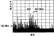
In the antenna assembly that there is no balanced-to-unblanced transformer 30 of the 3rd embodiment, partly produced zero point by the ground wire GND of equipment.But, as shown in Figure 31 A, Figure 31 B, Figure 32 A and Figure 32 B, can find out, play near the gain 520MHz of sleeve effect influenced hardly.
Figure 33 A and Figure 33 B are the figure that represents the mobile phone of the antenna assembly with balanced-to-unblanced transformer that adopts the 4th embodiment.Figure 33 A shows the main body of the mobile phone situation when closed, the situation when main body that Figure 33 B shows mobile phone is opened.
Example shown in Figure 33 A and Figure 33 B is the example that uses the antenna assembly 30A of the 210mm with balanced-to-unblanced transformer.
Figure 34 A and Figure 34 B are the figure that represents mobile phone relation between closed situation lower frequency and peak gain characteristic of the antenna assembly with balanced-to-unblanced transformer that adopts the 4th embodiment.Figure 34 A shows the characteristic of free space, characteristic when Figure 34 B shows mobile phone and is placed on human body.
Figure 35 A and 35B are the figure that represents mobile phone relation between the situation lower frequency of opening and peak gain characteristic of the antenna assembly with balanced-to-unblanced transformer that adopts the 4th embodiment.Figure 35 A shows the characteristic of free space, characteristic when Figure 35 B shows mobile phone and is placed on human body.
In Figure 34 A, Figure 34 B, Figure 35 A and Figure 35 B, shown the characteristic of horizontal polarization by " A " represented curve, shown the characteristic of perpendicular polarization by " B " represented curve.
In the antenna assembly 30A of the 4th embodiment, make the inner conductor 11 of cable be connected to realize sleeve antenna with the second outer conductor (braid shielded 2) 15 by balanced-to-unblanced transformer 52.
By this structure, as shown in Figure 34 A, Figure 34 B, Figure 35 A and Figure 35 B, can realize the ground wire GND of the equipment of not relying on and reduce the antenna of the impact while being provided on human body.
, antenna assembly 30A balance-imbalance converter of the 4th embodiment uses double layer screen simultaneously, thereby can be configured to the antenna that or not affected by equipment.
Figure 36 is the figure that has represented to adopt the mobile phone of the antenna assembly of the 5th embodiment, and wherein, a part for cable is removed.Figure 36 shows the main body of the mobile phone situation when closed.
Example shown in Figure 36 is the example that uses the antenna assembly 30B of the 210mm with balanced-to-unblanced transformer.
Figure 37 is the figure that is illustrated in relation between the situation lower frequency of mobile phone closure of the removed antenna assembly of a part that adopts the 5th embodiment cable and peak gain characteristic.Figure 37 shows the characteristic of free space.
In Figure 37, shown the characteristic of horizontal polarization by " A " represented curve, shown the characteristic of perpendicular polarization by " B " represented curve.
In the antenna assembly 30B of the 5th embodiment, even in the situation that cable is long, also just regulates resonance frequency by insulating case 16 and the second outer conductor 15 of removing double layer screen, thereby can be configured to linear dipole antenna.
As shown in figure 37, can find out, can be by removing the frequency that regulates antenna apart from the insulating case 16 of other end 160mm position and the second outer conductor 15.[there is or not existing the analysis of the characteristic of balanced-to-unblanced transformer]
Below, there is or not exist the characteristic of balanced-to-unblanced transformer in conjunction with the antenna explanation of dipole system.
Figure 38 represents that dipole antenna device is configured to the not figure of the example of three core coaxial configurations of balance-imbalance converter.
Figure 39 is the figure that represents mobile phone relation between closed situation lower frequency and peak gain characteristic of the antenna assembly that adopts Figure 38.Figure 39 shows the characteristic of free space.
In Figure 39, shown the characteristic of horizontal polarization by " A " represented curve, shown the characteristic of perpendicular polarization by " B " represented curve.
As shown in figure 38, show dipole aerial element 250 and be horizontally set, and as the mobile phone 200 of equipment body by vertically disposed example.
In the case, as shown in figure 39, although the polarized wave only receiving by dipole antenna is horizontal polarized wave, also partly receive near vertically polarized wave (MHz).
This shows to receive the radio wave being carried by coaxial cable.
Thereby, this means in the situation that not being provided with balanced-to-unblanced transformer, due to the impact of the length of cable and the size of equipment, at a part of frequency place, characteristic is improved, on the contrary, at another part frequency place, probably eliminating gain (cancel gain) can be lowered.
Figure 40 represents that dipole antenna device is configured to the figure of the example of three core coaxial configurations of balance-imbalance converter.
Figure 41 is the figure that represents mobile phone relation between closed situation lower frequency and peak gain characteristic of the antenna assembly that adopts Figure 40.Figure 41 shows the characteristic of free space.
In Figure 41, shown the characteristic of horizontal polarization by " A " represented curve, shown the characteristic of perpendicular polarization by " B " represented curve.
In Figure 40, configure like this antenna, prepare two elements (130mm) of 1/4 λ of 500MHz frequency to realize the resonance at UHF frequency band place of 470MHz~770MHz, and carry out balance-non-equilibrium conversion by balanced-to-unblanced transformer 260.
Can realize in theory and not receive the very wide and fabulous antenna that gains of vertically polarized wave, frequency band.
And, because antenna is extracted out from equipment by coaxial cable, thus can say this antenna be the noise of not receiving system and aspect noise fabulous antenna.
Thereby balance-imbalance converter 260 needs structure not rely on the antenna of cable.
Figure 42 is the figure that represents the variation example of the antenna assembly of Figure 40.
Figure 43 is the figure that represents mobile phone relation between closed situation lower frequency and peak gain characteristic of the antenna assembly that adopts Figure 42.Figure 43 shows the characteristic of free space.
In Figure 43, shown the characteristic of horizontal polarization by " A " represented curve, shown the characteristic of perpendicular polarization by " B " represented curve.
The antenna assembly of Figure 42 is that the element 252 of antenna is folded into the example of extending along cable.This element 252 is set to be parallel to coaxial cable 230, but apart from the distance of coaxial cable 230 about 1cm.
And in the case, antenna assembly is fabulous and play the effect of dipole aspect gain.
[analysis of foldable structure]
Figure 44 is the figure that represents the variation example of the antenna assembly of Figure 42.
Figure 45 is the figure that represents mobile phone relation between closed situation lower frequency and peak gain characteristic of the antenna assembly that adopts Figure 44.Figure 45 shows the characteristic of free space.
In Figure 45, shown the characteristic of horizontal polarization by " A " represented curve, shown the characteristic of perpendicular polarization by " B " represented curve.
The antenna assembly of Figure 44 is that element 252 is made as and is close to coaxial cable 230 and the example in state of insulation with regard to direct current.
In the case, as shown in figure 45, can find out the change in gain of characteristic significant change and 500MHz frequency band.
This is because the length of antenna element is extended on the composition length of coaxial cable 230 and equipment substrate.
Figure 46 represents that the length of substrate is from the figure of the example of the state change of Figure 44.
Figure 47 is the figure that represents mobile phone relation between closed situation lower frequency and peak gain characteristic of the antenna assembly that adopts Figure 46.Figure 47 shows the characteristic of free space.
In Figure 47, shown the characteristic of horizontal polarization by " A " represented curve, shown the characteristic of perpendicular polarization by " B " represented curve.
Figure 46 is the example that the length of substrate becomes 200mm × 50mm.
As shown in figure 47, can say that, by the change of substrate length, the change in gain of antenna is very big, and substrate and a part of antenna-coupled, thereby the characteristic changing of antenna.
That is, can say if cable is enough not large apart from the distance of substrate, be difficult to guarantee characteristic.
On the contrary, as the explanation of aforementioned combination Figure 33 A~Figure 35 B, the antenna assembly 30A with balanced-to-unblanced transformer of the 4th embodiment do not depend on equipment (mobile phone) main body ground wire GND and there is the antenna gain of improvement.
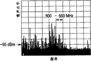
And, as the aforementioned explanation relevant to Figure 30 A~Figure 32 B, in the antenna assembly that there is no balanced-to-unblanced transformer 30 of the 3rd embodiment, although exist part to produce zero point the situation of (null), even but in the situation that there is no balanced-to-unblanced transformer, the 500MHz frequency band that coaxial trap works does not also have problems.
Thereby, by using the double layer screen cable of the present embodiment, and do not need to arrange in the situation that balanced-to-unblanced transformer configures antenna assembly, can obtain fabulous characteristic.But, by balance-imbalance converter, can be configured to the antenna that or not affected by equipment.
And, as shown in Figure 13 A~Figure 16 C, only, by the end processing of cable, just can configure sleeve part, thereby sleeve part can be configured to not utilize sheet metal, or ferrule element is as parts independently.Therefore, can very simply and at low cost configure antenna assembly, and can be only according to the rugosity of cable and balanced-to-unblanced transformer interval antenna arrangement.
And owing to not needing that dwi hastasana is become to the T shape as dipole antenna, so the configuration of parts also becomes simply, and this antenna can be used as linear antenna.
It will be appreciated by those skilled in the art that in the scope of claims or its equivalent, can carry out various modifications, combination, sub-portfolio and change according to design needs and other factors.
Claims (8)
1. an antenna assembly, it comprises:
Shielded type cable, it comprises the inner conductor, the first insulator, the first outer conductor, the second insulator and the second outer conductor that from inner side, coaxially arrange successively, and the periphery of described shielded type cable is insulated cover covering;
Receiver, it is connected to the first end of described shielded type cable by the first connecting portion, and described the first connecting portion is used for the power supply terminal of described receiver to be connected to described inner conductor, and the earth terminal of described receiver is connected to described the first outer conductor;
Antenna element, it is connected to the second end of described shielded type cable by the second connecting portion, and described the second connecting portion is used for described antenna element to be connected to described the first outer conductor, and described inner conductor is connected to described the second outer conductor,
Wherein, at least a portion of described shielded type cable is as the antenna that receives high-frequency signal.
2. antenna assembly as claimed in claim 1, wherein, described inner conductor comprises many first wires and filament, described filament is formed in the part outside described many first wires than the high material of described first wire by hot strength attribute.
3. antenna assembly as claimed in claim 2, wherein, the described filament with the material of described hot strength attribute is made up of aramid fiber.
4. the antenna assembly as described in any one in claim 1~3, wherein, at least one in described the first outer conductor and described the second outer conductor forms by weaving by first wire of many conductions the braid shielded forming.
5. the antenna assembly as described in any one in claim 1~3, wherein, has high-frequency resistance between described inner conductor and described the first outer conductor and between described the first outer conductor and described the second outer conductor.
6. the antenna assembly as described in any one in claim 1~3, wherein, the couple state of described the second insulator and described the first outer conductor is thicker than the couple state of described the second insulator and described the second outer conductor.
7. antenna assembly as claimed in claim 6 wherein, is provided with diaphragm seal between described the second insulator and described the first outer conductor.
8. the antenna assembly as described in any one in claim 1~3, wherein, described inner conductor is formed as many and insulated by the insulating material outside described the first insulator separately.
Applications Claiming Priority (2)
| Application Number | Priority Date | Filing Date | Title |
|---|---|---|---|
| JP2009-069089 | 2009-03-19 | ||
| JP2009069089A JP5487661B2 (en) | 2009-03-19 | 2009-03-19 | Shielded cable |
Publications (2)
| Publication Number | Publication Date |
|---|---|
| CN101840748A CN101840748A (en) | 2010-09-22 |
| CN101840748B true CN101840748B (en) | 2014-07-02 |
Family
ID=42153743
Family Applications (1)
| Application Number | Title | Priority Date | Filing Date |
|---|---|---|---|
| CN201010122090.3A Active CN101840748B (en) | 2009-03-19 | 2010-03-11 | Shielded cable |
Country Status (5)
| Country | Link |
|---|---|
| US (1) | US8080734B2 (en) |
| EP (1) | EP2230672B1 (en) |
| JP (1) | JP5487661B2 (en) |
| CN (1) | CN101840748B (en) |
| BR (1) | BRPI1003234B1 (en) |
Families Citing this family (24)
| Publication number | Priority date | Publication date | Assignee | Title |
|---|---|---|---|---|
| JP5338411B2 (en) * | 2009-03-19 | 2013-11-13 | ソニー株式会社 | Antenna device |
| JP4889764B2 (en) * | 2009-06-08 | 2012-03-07 | エス・ディ・ケイ株式会社 | Wiring cord |
| US20110209893A1 (en) * | 2010-02-26 | 2011-09-01 | Chun-Chieh Yu | Cable structure |
| KR101303274B1 (en) * | 2010-11-04 | 2013-09-03 | 신지앙 티안디 그룹 | Built-in type expansion and contraction earphone structure, and terminal device |
| JP6220113B2 (en) | 2011-02-17 | 2017-10-25 | 矢崎総業株式会社 | Manufacturing method of shield sleeve |
| US8497808B2 (en) * | 2011-04-08 | 2013-07-30 | Wang Electro-Opto Corporation | Ultra-wideband miniaturized omnidirectional antennas via multi-mode three-dimensional (3-D) traveling-wave (TW) |
| JP5978509B2 (en) * | 2011-07-25 | 2016-08-24 | 矢崎総業株式会社 | High voltage conductive path and wire harness |
| WO2013047033A1 (en) | 2011-09-26 | 2013-04-04 | 株式会社フジクラ | Antenna device and antenna mounting method |
| JP5947513B2 (en) * | 2011-09-27 | 2016-07-06 | 矢崎総業株式会社 | Braiding and wire harness |
| WO2013055624A2 (en) * | 2011-10-12 | 2013-04-18 | Entropic Communications, Inc. | Distributed continuous antenna |
| TW201401300A (en) * | 2012-06-26 | 2014-01-01 | Sumitomo Electric Industries | Multi-core cable |
| US20140008097A1 (en) * | 2012-07-09 | 2014-01-09 | Kyowa Electric Wire Co., Ltd. | Electric wire |
| KR20150095817A (en) * | 2012-12-13 | 2015-08-21 | 페더럴-모걸 파워트레인, 인코포레이티드 | Coaxial cable and method of construction thereof |
| DE102013223584A1 (en) * | 2013-04-26 | 2014-10-30 | Fraunhofer-Gesellschaft zur Förderung der angewandten Forschung e.V. | HIGH SPEED DATA CABLE |
| JP2015222627A (en) * | 2014-05-22 | 2015-12-10 | 日立金属株式会社 | Electric wire, harness, electric circuit, fabric, clothing and sheet |
| JP2015222626A (en) * | 2014-05-22 | 2015-12-10 | 日立金属株式会社 | Shielded wire, harness, electric surface, fabric, clothing and sheet |
| US10340057B2 (en) | 2015-11-24 | 2019-07-02 | Cisco Technology, Inc. | Unified power and data cable |
| BR112018016210A2 (en) * | 2016-02-15 | 2020-10-27 | Sony Corporation | cable. |
| JP2018133139A (en) * | 2017-02-13 | 2018-08-23 | 住友電装株式会社 | Protective member, high voltage cable for vehicle, and wire harness |
| US10971285B2 (en) | 2018-08-21 | 2021-04-06 | General Cable Technologies Corporation | Three-wire communication cable |
| CN111210928B (en) * | 2018-11-22 | 2022-05-06 | 北京小米移动软件有限公司 | Wire and USB data line |
| KR20200070788A (en) * | 2018-12-10 | 2020-06-18 | 넥쌍 | High-shielding light-weight cables including shielding layer of polymer-carbon composite |
| JP2020187974A (en) * | 2019-05-17 | 2020-11-19 | 矢崎総業株式会社 | Braided shield and shield electric wire |
| WO2021060075A1 (en) * | 2019-09-25 | 2021-04-01 | ソニーセミコンダクタソリューションズ株式会社 | Cable and antenna device equipped with coaxial cable |
Citations (2)
| Publication number | Priority date | Publication date | Assignee | Title |
|---|---|---|---|---|
| US4642417A (en) * | 1984-07-30 | 1987-02-10 | Kraftwerk Union Aktiengesellschaft | Concentric three-conductor cable |
| CN2701038Y (en) * | 2004-05-18 | 2005-05-18 | 李明斌 | Coaxial screening cable for communication |
Family Cites Families (16)
| Publication number | Priority date | Publication date | Assignee | Title |
|---|---|---|---|---|
| US4376920A (en) * | 1981-04-01 | 1983-03-15 | Smith Kenneth L | Shielded radio frequency transmission cable |
| US4641110A (en) * | 1984-06-13 | 1987-02-03 | Adams-Russell Company, Inc. | Shielded radio frequency transmission cable having propagation constant enhancing means |
| FR2660481B1 (en) * | 1990-03-27 | 1994-06-10 | Thomson Video Equip | ELECTRICAL AND OPTICAL MIXED CABLE AND APPLICATION TO THE LINK BETWEEN A CAMERA HEAD AND A CONTROL UNIT. |
| US5414213A (en) * | 1992-10-21 | 1995-05-09 | Hillburn; Ralph D. | Shielded electric cable |
| JP3442822B2 (en) * | 1993-07-28 | 2003-09-02 | アジレント・テクノロジー株式会社 | Measurement cable and measurement system |
| JPH10334750A (en) * | 1997-05-30 | 1998-12-18 | Hitachi Cable Ltd | Extra fin multicore coaxial cable with bending proof |
| JP4723123B2 (en) | 2001-06-20 | 2011-07-13 | マスプロ電工株式会社 | Sleeve antenna |
| US6815617B1 (en) * | 2002-01-15 | 2004-11-09 | Belden Technologies, Inc. | Serrated cable core |
| JP4012414B2 (en) | 2002-02-25 | 2007-11-21 | マスプロ電工株式会社 | Dual frequency shared sleeve antenna |
| US6800810B1 (en) * | 2002-09-03 | 2004-10-05 | William Jody Page | Snake for musical instrument wiring |
| US6847219B1 (en) * | 2002-11-08 | 2005-01-25 | Cascade Microtech, Inc. | Probe station with low noise characteristics |
| JP4107982B2 (en) * | 2003-03-07 | 2008-06-25 | ハラダテクノ株式会社 | coaxial cable |
| JP2005197130A (en) * | 2004-01-08 | 2005-07-21 | Yazaki Corp | Coaxial cable |
| US20060011376A1 (en) * | 2004-07-16 | 2006-01-19 | General Electric Company | Multi-axial electrically conductive cable with multi-layered core and method of manufacture and use |
| JP5124902B2 (en) * | 2004-12-09 | 2013-01-23 | ソニー株式会社 | Shielded cable |
| JP5191712B2 (en) | 2007-09-18 | 2013-05-08 | 日置電機株式会社 | Current measuring device |
-
2009
- 2009-03-19 JP JP2009069089A patent/JP5487661B2/en active Active
-
2010
- 2010-03-08 EP EP10250417A patent/EP2230672B1/en active Active
- 2010-03-09 US US12/720,344 patent/US8080734B2/en active Active
- 2010-03-11 CN CN201010122090.3A patent/CN101840748B/en active Active
- 2010-03-12 BR BRPI1003234-7A patent/BRPI1003234B1/en active IP Right Grant
Patent Citations (2)
| Publication number | Priority date | Publication date | Assignee | Title |
|---|---|---|---|---|
| US4642417A (en) * | 1984-07-30 | 1987-02-10 | Kraftwerk Union Aktiengesellschaft | Concentric three-conductor cable |
| CN2701038Y (en) * | 2004-05-18 | 2005-05-18 | 李明斌 | Coaxial screening cable for communication |
Also Published As
| Publication number | Publication date |
|---|---|
| US8080734B2 (en) | 2011-12-20 |
| BRPI1003234B1 (en) | 2019-08-20 |
| EP2230672B1 (en) | 2013-03-06 |
| CN101840748A (en) | 2010-09-22 |
| EP2230672A3 (en) | 2012-06-27 |
| BRPI1003234A2 (en) | 2012-02-07 |
| JP5487661B2 (en) | 2014-05-07 |
| US20100236810A1 (en) | 2010-09-23 |
| EP2230672A2 (en) | 2010-09-22 |
| JP2010225333A (en) | 2010-10-07 |
Similar Documents
| Publication | Publication Date | Title |
|---|---|---|
| CN101840748B (en) | Shielded cable | |
| CN101853984B (en) | Antenna device | |
| CN100583553C (en) | Earphone antenna and portable radio equipment provided with earphone antenna | |
| US7236137B2 (en) | Earphone antenna, composite coil and coaxial cable used therefor, and wireless device provided with the earphone antenna | |
| CN102422489B (en) | Antenna device | |
| CN101443955B (en) | Antenna system | |
| CN101752661A (en) | Power supply device, power cable and reception device | |
| KR101646787B1 (en) | Receiving apparatus | |
| US8379900B2 (en) | Connecting device, antenna device, and receiving device | |
| CN100452531C (en) | Earphone antenna and portable radio equipment provided with earphone antenna | |
| CN107123857B (en) | Antenna device and receiving device | |
| KR20050113620A (en) | Antenna device and antenna device manufacturing method | |
| US20060290578A1 (en) | Digital receiving antenna device for a digital television | |
| JP2005159727A (en) | Antenna system | |
| JP5526603B2 (en) | Antenna device | |
| JP5521391B2 (en) | Antenna device | |
| JPH09275307A (en) | Coupler for coaxial cable and antenna system | |
| JPH01177202A (en) | Antenna for movable body |
Legal Events
| Date | Code | Title | Description |
|---|---|---|---|
| C06 | Publication | ||
| PB01 | Publication | ||
| C10 | Entry into substantive examination | ||
| SE01 | Entry into force of request for substantive examination | ||
| C14 | Grant of patent or utility model | ||
| GR01 | Patent grant |