CN101815169A - Filming apparatus - Google Patents

Filming apparatus Download PDF

Info

Publication number
CN101815169A
CN101815169A CN201010126340A CN201010126340A CN101815169A CN 101815169 A CN101815169 A CN 101815169A CN 201010126340 A CN201010126340 A CN 201010126340A CN 201010126340 A CN201010126340 A CN 201010126340A CN 101815169 A CN101815169 A CN 101815169A
Authority
CN
China
Prior art keywords
moving image
capacity information
image
rest image
shows
Prior art date
Legal status (The legal status is an assumption and is not a legal conclusion. Google has not performed a legal analysis and makes no representation as to the accuracy of the status listed.)
Pending
Application number
CN201010126340A
Other languages
Chinese (zh)
Inventor
青木泰造
上田裕贵
Current Assignee (The listed assignees may be inaccurate. Google has not performed a legal analysis and makes no representation or warranty as to the accuracy of the list.)
Panasonic Intellectual Property Corp of America
Original Assignee
Matsushita Electric Industrial Co Ltd
Priority date (The priority date is an assumption and is not a legal conclusion. Google has not performed a legal analysis and makes no representation as to the accuracy of the date listed.)
Filing date
Publication date
Application filed by Matsushita Electric Industrial Co Ltd filed Critical Matsushita Electric Industrial Co Ltd
Publication of CN101815169A publication Critical patent/CN101815169A/en
Pending legal-status Critical Current

Links

Images

Classifications

    • HELECTRICITY
    • H04ELECTRIC COMMUNICATION TECHNIQUE
    • H04NPICTORIAL COMMUNICATION, e.g. TELEVISION
    • H04N5/00Details of television systems
    • H04N5/76Television signal recording
    • H04N5/765Interface circuits between an apparatus for recording and another apparatus
    • H04N5/77Interface circuits between an apparatus for recording and another apparatus between a recording apparatus and a television camera
    • H04N5/772Interface circuits between an apparatus for recording and another apparatus between a recording apparatus and a television camera the recording apparatus and the television camera being placed in the same enclosure
    • HELECTRICITY
    • H04ELECTRIC COMMUNICATION TECHNIQUE
    • H04NPICTORIAL COMMUNICATION, e.g. TELEVISION
    • H04N23/00Cameras or camera modules comprising electronic image sensors; Control thereof
    • H04N23/60Control of cameras or camera modules
    • H04N23/63Control of cameras or camera modules by using electronic viewfinders
    • H04N23/633Control of cameras or camera modules by using electronic viewfinders for displaying additional information relating to control or operation of the camera
    • HELECTRICITY
    • H04ELECTRIC COMMUNICATION TECHNIQUE
    • H04NPICTORIAL COMMUNICATION, e.g. TELEVISION
    • H04N5/00Details of television systems
    • H04N5/76Television signal recording
    • H04N5/907Television signal recording using static stores, e.g. storage tubes or semiconductor memories
    • HELECTRICITY
    • H04ELECTRIC COMMUNICATION TECHNIQUE
    • H04NPICTORIAL COMMUNICATION, e.g. TELEVISION
    • H04N9/00Details of colour television systems
    • H04N9/79Processing of colour television signals in connection with recording
    • H04N9/7921Processing of colour television signals in connection with recording for more than one processing mode
    • HELECTRICITY
    • H04ELECTRIC COMMUNICATION TECHNIQUE
    • H04NPICTORIAL COMMUNICATION, e.g. TELEVISION
    • H04N9/00Details of colour television systems
    • H04N9/79Processing of colour television signals in connection with recording
    • H04N9/80Transformation of the television signal for recording, e.g. modulation, frequency changing; Inverse transformation for playback
    • H04N9/804Transformation of the television signal for recording, e.g. modulation, frequency changing; Inverse transformation for playback involving pulse code modulation of the colour picture signal components
    • H04N9/8042Transformation of the television signal for recording, e.g. modulation, frequency changing; Inverse transformation for playback involving pulse code modulation of the colour picture signal components involving data reduction
    • H04N9/8047Transformation of the television signal for recording, e.g. modulation, frequency changing; Inverse transformation for playback involving pulse code modulation of the colour picture signal components involving data reduction using transform coding

Abstract

Filming apparatus, but taking moving image and rest image comprise: record cell, will be by taking the moving image that the unit generates or the Imagery Data Recording of rest image to recording medium; Display unit in moving image capture, shows the 1st capacity information about the time of recordable moving image in the recording medium; In rest image is taken, show the 2nd capacity information about the number of recordable rest image in the recording medium.Display unit finishes the back until through till the time of appointment at moving image capture, continues to show the 1st capacity information; Take the end back until through till the time of appointment at rest image, continue to show the 2nd capacity information.After the fixed time process, display unit shows one of them of the 1st capacity information and the 2nd capacity information.But by representing to improve the user convenience degree about the information of recording capacity.

Description

Filming apparatus
Technical field
The present invention relates to a kind of can the taking moving image and the filming apparatus of rest image, but the particularly a kind of filming apparatus that can point out about the information of the recording capacity of moving image and rest image.
Background technology
In the patent documentation 1, a kind of tape deck that can write down moving image and rest image is disclosed.This tape deck shows the surplus of recording medium in the record rest image with number; In the record moving image, with the surplus of recording medium with time showing.Thus, the user also can with arbitrary situation of moving image or rest image, correctly learn the surplus of memory at short notice under the situation of moving image and rest image hybrid recording.
Patent documentation 1: Japanese kokai publication hei 1-326172 communique
In recent years, the capacity of recording medium has the tendency that increases day by day, and along with the increase of capacity, the capacity of recordable moving image of filming apparatus and rest image is also increasing.For the user, but knowing the recording capacity of filming apparatus, is very important.Thus, but just wish the information of energy, show clearly to the user with the recording capacity of relevant filming apparatus.In addition, because nearest filming apparatus shows a lot of information in display frame, thus, just wish to realize preventing to obscure and effectively utilize display frame.
Summary of the invention
But the object of the invention is to provide the information of the relevant recording capacity of expression, and improves the filming apparatus of user convenience degree.
Among the present invention, provide a kind of can the taking moving image and the filming apparatus of rest image.Filming apparatus comprises: take the unit, take shot object image, generate view data; Record cell will be by taking the moving image that the unit generates or the Imagery Data Recording of rest image to recording medium; Display unit in moving image capture, shows the 1st capacity information about the time of recordable moving image in the recording medium, and in rest image is taken, shows the 2nd capacity information about the number of recordable rest image in the recording medium.Display unit until through till the time of appointment, continues to show the 1st capacity information, and takes the end back until through till the time of appointment at rest image after moving image capture finishes, and continues to show the 2nd capacity information.After the fixed time process, display unit shows one of them of the 1st capacity information and the 2nd capacity information.
According to the present invention, but the shooting time of the number taken of rest image and moving image does not show simultaneously on monitor.Thus, just can prevent obscuring of time that number that the user can take rest image and moving image can be taken, the convenient degree of filming apparatus is improved.In addition, take within the end fixed time afterwards, but continue to show shooting time or can take number at moving image and rest image.Thus, but the user to shooting time or can take number just is easy to visually distinguish.
Description of drawings
The module map of the digital camera that Fig. 1 execution mode 1 is related.
The flow chart that monitor in Fig. 2 screening-mode shows.
The pictorial image that Fig. 3 shows for the monitor in the explanation screening-mode.
The flow chart that monitor during Fig. 4 menu is selected shows.
The pictorial image that Fig. 5 shows for the monitor in the selection of explanation menu.
Among the figure:
100 digital cameras
110 optical systems
120 lens driving portions
130 shutters
The 140CCD imageing sensor
The 150A/D transducer
160 image processing parts
170 buffers
180 controllers
190 card slots
200 storage cards
210 functional units
220 display monitors
Embodiment
Following with reference to description of drawings the specific embodiment of the present invention.
1. execution mode 1
The 1-1 summary
The digital camera that present embodiment is related, but taking moving image and rest image.But digital camera is with the shooting time of moving image, be presented on the display monitor with one of them of the number taken of rest image, under such situation, but only there be one of them of the number taken of the shooting time of moving image and rest image optionally to be shown on the display monitor.
The 1-2 structure
The 1-2-1 electrical construction
Utilize Fig. 1, the structure of the digital camera of present embodiment is described.Digital camera 100 by ccd image sensor 140, is taken the optical system 110 formed shot object images of being made up of 1 or a plurality of lens.View data by ccd image sensor 140 generates is implemented various processing at image processing part 160, is stored in storage card 200.The structure of following logarithmic code camera 100 is elaborated.
Optical system 110 is made up of varifocal mirror and focusing mirror etc.Allow varifocal mirror move along optical axis, shot object image is just scalable and dwindle.In addition, allow the focusing mirror move, just can adjust the focus of shot object image along optical axis.
Lens driving portion 120 drives the various lens that comprise in the optical system 110.For example drive the zoom motor (motor) of varifocal mirror, the focusing motor of driving focusing mirror etc. and just be equivalent to this.
Aperture 300 is according to user's setting or automatically, the size in adjustment aperture is adjusted the light quantity that sees through.
Shutter 130 is for covering the unit of the light that sees through to ccd image sensor 140.
Ccd image sensor 140 is taken by optical system 110 formed shot object images, generates view data.Various operations such as ccd image sensor 140 exposes, transmission, electronic shutter.
A/D converter 150 will be converted to DID by the simulated image data that ccd image sensor 140 generates.
160 pairs of view data that generated by ccd image sensor 140 of image processing part are implemented various processing.The view data that 160 pairs of image processing parts are generated by ccd image sensor 140 are implemented to handle, and are created on the view data that shows on the display monitor 220, and the view data etc. that is created on storage in the storage card 200.For example, 160 pairs of view data that generated by ccd image sensor 140 of image processing part are implemented various processing such as gamma correction, white balance compensation, damage correction.In addition, the view data that 160 pairs of image processing parts are generated by ccd image sensor 140, with according to the compressed format of Joint Photographic Experts Group with Image Data Compression.Image processing part 160 can be by realizations such as DSP, microcomputers.
Controller 180 is the whole control units of control.Controller 180 can be by realizations such as semiconductor elements.Controller 180 can only be made of hardware, also can be realized by the combination of hardware and software.Controller 180 can be by realizations such as microcomputers.
Buffer 170 is as the working storage of image processing part 160 and controller 180 and work.Buffer 170 can be by for example realization such as DRAM, ferroelectric memory.
Card slot 190 can be installed and removed storage card 200.Card slot 190 can and be electrically connected with storage card 200 machineries.Storage card 200 contains flash memory or ferroelectric memory etc. in inside, can be stored in the data such as image file that image processing part 160 generates.
Internal storage 240 is made of flash memory or ferroelectric memory etc.Internal storage 240 has been stored to the control program of control digital camera 100 integral body etc.
Functional unit 210 is reception general names from the user interface of user's operation.For example, comprise that reception is from the cross key of user's operation and confirming button etc.In addition, functional unit 210 also comprises the moving image capture start button 212 of shutter release button 211 that the shooting of indication rest image begins and the beginning of indicating moving image capture etc.Shutter release button 211 and moving image capture start button 212 are independent separately to be provided with.The user can set the mode of operation of digital camera 100 by the operation to functional unit 210.Mode of operation has the taking moving image or the screening-mode of rest image and reproduces the reproduction mode of shot image data.
Display monitor 220 may be displayed on represented image (direct picture, ス Le one portrait) and the represented image of the view data of reading of view data that ccd image sensor 140 generates from storage card 200.Direct picture is to be presented in real time after being taken by ccd image sensor 140 on the display monitor 220 but not to be recorded in the image of storage card 200.Direct picture mainly is a moving image, is decision composition and be presented at display monitor 220 when being used for the user and taking rest image.In addition, display monitor 220 can also show various various menu screens that are set at purpose to carry out digital camera 100 etc.As the information about the residual capacity of storage card 200, but display monitor 220 shows the shooting time of moving image when the shooting of moving image, shows the number taken of rest image when the shooting of rest image.Under the situation outside the shooting of moving image and rest image, display monitor 220 is according to the setting of appointment, but on direct picture one of them of the shooting time of overlapping demonstration moving image or the number taken of rest image.To call be set at " display setting of the residual capacity of storage card " of this appointment in the following text.The display setting of the residual capacity of storage card can be set arbitrarily by the user.
The correspondence of 1-2-2 term
Ccd image sensor 140 is examples taking the unit.Storage card 200 is examples of memory cell.Display monitor 220 is examples of display unit.Functional unit 210 is examples of receiving element.
1-3 work
Monitor during the 1-3-1 moving image capture shows
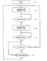
The digital camera 100 of present embodiment can be taken rest image and moving image.Utilize Fig. 2 and Fig. 3, the monitor the during moving image capture of logarithmic code camera 100 shows and describes.Fig. 2 is the flow chart that monitor shows during for the account for motion image taking.Fig. 3 is the pictorial image that the monitor during for the account for motion image taking shows.
Set at digital camera 100 under the state of screening-mode, the user can carry out the shooting of rest image by pressing shutter release button 211.In addition, set at digital camera 100 under the state of screening-mode, the user can carry out the shooting of moving image by pressing moving image capture start button 212.
Display setting about the residual capacity of storage card, the user operates by the designated button (for example menu button) to functional unit 210, can set the information that allows about the number taken of rest image, but with about one of them of the information of the shooting time of moving image, be shown in display monitor 220.But the shooting time of the number taken of still image and moving image calculates based on residual capacity of storage card 200 etc.
Following with reference to Fig. 2, the control that the monitor during to moving image capture shows describes.In addition, the following description with the display setting of the residual capacity of storage card, is set at the number taken that shows rest image on display monitor 220.
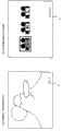
The user can be set at digital camera 100 screening-mode (S100) by the designated button of functional unit 210 is operated.Setting for screening-mode after, controller 180 shows according to the display setting of the residual capacity of storage card.Herein, controller 180 shows the number taken of rest image on display monitor 220.Specifically, controller 180 based on the residual capacity of storage card 200, calculates the number of the rest image that can take, and the information of calculating about taking number is shown (S110) on display monitor 220.For example, shown in Fig. 3 (A), display monitor 220 has shown direct picture, has also shown the number the taken A of rest image.
Afterwards, controller 180 is judged that users have or not and is pressed moving image capture start button 212 (S120).When judging moving image capture start button 212 and be pressed, controller 180 begins the view data that is generated at image processing part 160 is noted down to storage card 200, but calculate the shooting time of moving image by the residual capacity of storage card 200 etc., on display monitor 220, show (S130).For example, shown in Fig. 3 (B), display monitor 220 has shown direct picture, but has also shown the shooting time B of moving image.Consider user's Yi Jiandu, but shooting time B is preferably and can takes number A in identical position display.In addition, thus, can take number and the position display that the time can limit can be set.This point is very favourable for the demonstration on little liquid crystal panel especially.
After this, controller 180 is judged to have or not and is stopped indication (S140) from user's moving image capture.When judge moving image capture stop to indicate the time, controller 180 is judged from the indication that stops that receiving moving image capture and is had or not and pass through the fixed time (S150).Fixed time was made as 5 seconds.Yet, not necessarily must be 5 seconds.As the fixed time, arbitrary value such as can adopt 3 seconds, 7 seconds.In addition, at this constantly, but display monitor 220 shows the shooting time of moving image.
When judging, when having passed through the time of appointment, just get back to demonstration according to the display setting of the residual capacity of storage card from receiving the indication that stops of moving image capture.That is to say that controller 180 calculates the number taken of rest image by residual capacity of storage card 200 etc., and the number taken of calculating is shown (S110) on display monitor 220.
On the other hand, when judging from receiving the indication that stops of moving image capture, when also not passing through the time of appointment, controller 180 judges that the shooting that has or not rest image indicates, and that is to say, the user has or not and presses shutter release button 211 (S160).When judging the shooting indication of rest image, even controller 180 does not pass through the fixed time, also calculate the number taken of rest image, the information about taking number that calculates is shown (S110) on display monitor 220 by residual capacity of storage card 200 etc.On the other hand, when being judged as shooting when indication that does not have rest image, controller 180 is judged once more to have or not and is passed through the fixed time (S150).Like this, stopping after the indication of moving image capture, to the fixed time through till, if there is not the indication of the shooting of rest image, but just continue on display monitor 220, to show the shooting time of moving image.
As mentioned above, the digital camera 100 of present embodiment, even display setting as the residual capacity of storage card, be that the number taken that is set at rest image is shown in display monitor 220, also can be when moving image capture begin, but the shooting time of moving image is shown on display monitor 220.Thus, the user when the taking moving image, but can recognize the shooting time of moving image by display monitor 220.
In addition, digital camera 100 after the stop motion image taking to the fixed time through before, the demonstration of display monitor 220 does not switch to the number taken of rest image, but continues to show on display monitor 220 shooting time of moving image.Its reason is, after the shooting of moving image stopped, in the short period, the possibility of shooting of restarting moving image was higher.Thus, even the user after the shooting of moving image stops, wanting to restart under the situation of moving image capture immediately, but also can recognize the shooting time of moving image.
In addition, the digital camera 100 that present embodiment is related, after moving image capture stops, to the fixed time process, under the situation that shutter release button 211 is pressed (situation that the indication of taking from user's rest image is arranged), on display monitor 220, show the number taken of rest image immediately.Its reason is, carries out rest image when pressing shutter release button 211 by the user and takes, and the possibility of shooting of carrying out rest image within a short period of time once more is higher, and demonstration can be taken number, has then complied with the user convenience degree.
Monitor when the 1-3-2 menu is selected shows
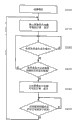
Next, utilize Fig. 4, Fig. 5, the control that the monitor the when menu of logarithmic code camera 100 is selected shows describes.Fig. 4 is the flow chart that the monitor when selecting for the explanation menu shows.Fig. 5 is the pictorial image that the monitor when selecting for the explanation menu shows.
The user operates by the designated button (for example menu button) to functional unit 210, digital camera 100 can be set at screening-mode (S200).When being set at screening-mode, controller 180 calculates the number of the rest image that can take based on the residual capacity of storage card 200, and the information about taking number that calculates is shown (S210) on display monitor 220.For example, shown in Fig. 5 (A), display monitor 220 has shown direct picture, has also shown the number the taken A of rest image.
Afterwards, controller 180 is judged the demonstration (S220) that has or not the menu screen that the user operates the button of the appointment of functional unit 210 on display monitor 220.
When the demonstration of menu screen was arranged on judging display monitor 220, controller 180 judged whether the menu screen that shows on the display monitor 220 is the relevant menu screen (S230) of moving image capture.Herein, the menu screen that moving image capture is relevant for example shown in Fig. 5 (B), comprises the picture of the pixel count of the moving image of selecting shooting.Among Fig. 5 (B), " SH " meaning is full HD moving image, and " H " meaning is the high definition moving image, and " L " meaning is the SD moving image.
When judging display monitor 220 and showing the relevant menu screen of moving image capture, but controller 180 calculates the shooting time of moving image by the residual capacity of storage card 200 etc., shows on display monitor 220 (S240).For example, shown in Fig. 5 (B), display monitor 220 has shown the relevant menu screen of moving image capture, but has also shown the shooting time B of moving image.
After this, controller 180 is judged the indication (S250) that has or not from the demonstration of the relevant menu screen of user's end moving image capture.When the indication judged from the demonstration of the relevant menu screen of user's end moving image capture, controller 180 calculates the number taken of rest image by residual capacity of storage card 200 etc., and the number taken of calculating is shown (S210) on display monitor 220.On the other hand, when judging the indication of the demonstration that does not finish the relevant menu screen of moving image capture, but controller 180 just continues to show the information about the shooting time of moving image on display monitor 220.
As mentioned above, digital camera 100, even the number taken that is set at rest image is shown in display monitor 220, when also can on display monitor 220, show, but the shooting time of moving image is shown on display monitor 220 at the menu screen that moving image capture is correlated with.Thus, display setting as the residual capacity of storage card, even the number taken that is set at rest image is shown in display monitor 220, the user when carrying out the relevant setting of moving image capture, but also can recognize the shooting time of moving image.
2. other execution mode
Above-mentioned example as embodiments of the present invention is illustrated, and describes following for other execution mode.
In the above-mentioned example, as taking the unit, use be ccd image sensor 140, also can use cmos image sensor, or NMOS imageing sensor etc.
In addition, image processing part 160 and controller 180 both can constitute on a semiconductor chip, also can constitute on semiconductor chip separately.
In addition, in the above-mentioned execution mode, be moving image capture is finished after, until the fixed time through till, but show that the example of the shooting time of moving image describes, and after the shooting of rest image finishes, also can carry out same control.That is to say, also can after rest image is taken end, till the fixed time process, continue to show the number taken of rest image.Particularly, but under the situation that the shooting of rest image begins when the shooting time of moving image shows on display monitor 220, the number taken of demonstration rest image on display monitor 220.Afterwards, also can take finish within the time of back appointment at rest image, continue to show and can take number, afterwards, the display setting according to the residual capacity of storage card shows again.
In addition, in the above-mentioned execution mode, be when the relevant menu screen of moving image capture shows on display monitor 220, but the shooting time of moving image is presented on the display monitor 220, similarly, also can be when rest image be taken relevant menu screen and be shown on display monitor 220, the number taken of rest image is presented on the display monitor 220.
The present invention is applicable to can the taking moving image and the device of rest image, for example, and the filming apparatus that digital camera, Digital Video are such and have mobile phone of camera function etc.

Claims (6)

1. filming apparatus can taking moving image and rest image, and described filming apparatus comprises:
Take the unit, take shot object image, generate view data;
Record cell, the moving image that will be generated by described shooting unit or the Imagery Data Recording of rest image are to recording medium; With
Display unit, in moving image capture, demonstration in rest image is taken, shows the 2nd capacity information about the number of recordable rest image in the described recording medium about the 1st capacity information of the time of recordable moving image in the described recording medium;
Described display unit is even still continue to show described the 1st capacity information, till the fixed time process, even still continue to show described the 2nd capacity information after the rest image shooting finishes, till the fixed time process after moving image capture finishes;
After the described fixed time process, described display unit shows one of them of described the 1st capacity information and described the 2nd capacity information.
2. filming apparatus according to claim 1 is characterized in that:
Also further comprise: receiving element receives the shooting indication from user's rest image;
Described display unit even finish before the back at the appointed time passes through at moving image capture, under described receiving element receives situation from the shooting indication of user's rest image, then shows described the 2nd capacity information.
3. filming apparatus according to claim 1 is characterized in that:
Also further comprise: receiving element receives the shooting indication from user's moving image;
Described display unit even take to finish before the back at the appointed time passes through at rest image, under described receiving element receives situation from the shooting indication of user's moving image, then shows described the 1st capacity information.
4. filming apparatus according to claim 1 is characterized in that:
Described display unit under the situation of demonstration about the operation screen of moving image capture, shows described the 1st capacity information.
5. filming apparatus according to claim 1 is characterized in that:
Described display unit under the situation that shows the operation screen of taking about rest image, shows described the 2nd capacity information.
6. filming apparatus according to claim 1 is characterized in that:
Described display unit with described the 1st capacity information and described the 2nd capacity information, is presented at the same position on the picture.
CN201010126340A 2009-02-25 2010-02-24 Filming apparatus Pending CN101815169A (en)

Applications Claiming Priority (2)

Application Number Priority Date Filing Date Title
JP2009-041942 2009-02-25
JP2009041942 2009-02-25

Publications (1)

Publication Number Publication Date
CN101815169A true CN101815169A (en) 2010-08-25

Family

ID=42622280

Family Applications (1)

Application Number Title Priority Date Filing Date
CN201010126340A Pending CN101815169A (en) 2009-02-25 2010-02-24 Filming apparatus

Country Status (3)

Country Link
US (1) US8228393B2 (en)
JP (1) JP5433459B2 (en)
CN (1) CN101815169A (en)

Families Citing this family (3)

* Cited by examiner, † Cited by third party
Publication number Priority date Publication date Assignee Title
US8687075B2 (en) * 2010-03-17 2014-04-01 Panasonic Corporation Imaging apparatus and information display method for imaging apparatus
JP5665345B2 (en) * 2010-03-31 2015-02-04 キヤノン株式会社 Imaging apparatus and control method thereof
JP2020074117A (en) * 2019-12-26 2020-05-14 アマノ株式会社 Business processing device, information processing method, and program

Citations (7)

* Cited by examiner, † Cited by third party
Publication number Priority date Publication date Assignee Title
US5905528A (en) * 1995-08-23 1999-05-18 Olympus Optical Co., Ltd. Apparatus having a moving picture recording mode and a still picture recording mode and which is capable of simultaneously displaying a remaining memory capacity with respect to each of the recording modes
JP2000299800A (en) * 1999-04-12 2000-10-24 Canon Inc Image pickup method and device and storage medium
JP2001016490A (en) * 1999-06-29 2001-01-19 Canon Inc Image pickup unit and method for processing image pickup data
JP2001069442A (en) * 1999-08-26 2001-03-16 Olympus Optical Co Ltd Electronic camera
JP2003244614A (en) * 2002-02-15 2003-08-29 Minolta Co Ltd Digital camera
CN1941846A (en) * 2000-05-31 2007-04-04 富士胶片株式会社 Image quality selecting method and digital camera
CN1968391A (en) * 2005-11-18 2007-05-23 索尼株式会社 Photographing apparatus, display control method, and program

Family Cites Families (15)

* Cited by examiner, † Cited by third party
Publication number Priority date Publication date Assignee Title
JP3618770B2 (en) * 1993-07-16 2005-02-09 キヤノン株式会社 Imaging device
JP3599369B2 (en) 1994-06-02 2004-12-08 キヤノン株式会社 Recording device
JPH1013721A (en) * 1996-06-20 1998-01-16 Hitachi Ltd Image pickup device
JP2004228826A (en) * 2003-01-22 2004-08-12 Fuji Photo Film Co Ltd Recording time calculation device for moving image and its method
JP2004350129A (en) 2003-05-23 2004-12-09 Ricoh Co Ltd Digital camera
US20050093988A1 (en) * 2003-11-03 2005-05-05 Haas William R. Digital camera with automatic mode detection
JP4308681B2 (en) 2004-02-19 2009-08-05 株式会社リコー Imaging device
JP2005318261A (en) * 2004-04-28 2005-11-10 Toshiba Corp Electronic camera apparatus, and recording management method of electronic camera apparatus
JP2006174166A (en) 2004-12-16 2006-06-29 Canon Inc Electronic camera and control method therefor
JP4770544B2 (en) * 2005-06-16 2011-09-14 カシオ計算機株式会社 Imaging apparatus, method for displaying recording capacity of recording medium, and program
JP2007194804A (en) * 2006-01-18 2007-08-02 Sony Corp Photographing device and method, reproducing device and method, and program
JP2008301014A (en) * 2007-05-30 2008-12-11 Fujifilm Corp Photographing apparatus and method, and program
JP5495670B2 (en) * 2009-08-20 2014-05-21 キヤノン株式会社 Imaging device, control method thereof, and program
US8687075B2 (en) * 2010-03-17 2014-04-01 Panasonic Corporation Imaging apparatus and information display method for imaging apparatus
JP5665345B2 (en) * 2010-03-31 2015-02-04 キヤノン株式会社 Imaging apparatus and control method thereof

Patent Citations (7)

* Cited by examiner, † Cited by third party
Publication number Priority date Publication date Assignee Title
US5905528A (en) * 1995-08-23 1999-05-18 Olympus Optical Co., Ltd. Apparatus having a moving picture recording mode and a still picture recording mode and which is capable of simultaneously displaying a remaining memory capacity with respect to each of the recording modes
JP2000299800A (en) * 1999-04-12 2000-10-24 Canon Inc Image pickup method and device and storage medium
JP2001016490A (en) * 1999-06-29 2001-01-19 Canon Inc Image pickup unit and method for processing image pickup data
JP2001069442A (en) * 1999-08-26 2001-03-16 Olympus Optical Co Ltd Electronic camera
CN1941846A (en) * 2000-05-31 2007-04-04 富士胶片株式会社 Image quality selecting method and digital camera
JP2003244614A (en) * 2002-02-15 2003-08-29 Minolta Co Ltd Digital camera
CN1968391A (en) * 2005-11-18 2007-05-23 索尼株式会社 Photographing apparatus, display control method, and program

Also Published As

Publication number Publication date
US8228393B2 (en) 2012-07-24
US20100214427A1 (en) 2010-08-26
JP5433459B2 (en) 2014-03-05
JP2010252306A (en) 2010-11-04

Similar Documents

Publication Publication Date Title
US8773569B2 (en) Image capturing apparatus and image capturing apparatus control method
JP5383356B2 (en) IMAGING DEVICE, INFORMATION PROCESSING DEVICE, IMAGING DEVICE CONTROL METHOD, INFORMATION PROCESSING DEVICE CONTROL METHOD, AND COMPUTER PROGRAM
CN102739961B (en) Can the image processing apparatus of generating wide angle
CN101237529A (en) Imaging apparatus and imaging method
JP5681871B2 (en) Imaging apparatus, imaging method, and program
US9871970B2 (en) Imaging apparatus, control method, and storage medium storing program
CN102739962A (en) Image processing device capable of generating wide-range image
CN102761692A (en) Imaging apparatus and method for controlling the same
JP5988860B2 (en) IMAGING DEVICE AND IMAGING DEVICE CONTROL METHOD
US7046275B1 (en) Digital camera and imaging method
US7064784B2 (en) Image pickup apparatus adapted to carry out parallel operations in a continuous image pickup mode, and a control method
JP2007208903A (en) Photographic system and photographic instruction apparatus
JP2005236883A (en) Photographing apparatus
CN101815169A (en) Filming apparatus
JP2013258469A (en) Control device, recording device, imaging device, and program
US7750965B2 (en) Image pickup apparatus
JP4612874B2 (en) Imaging apparatus and control method thereof
US20060290803A1 (en) Image-pickup apparatus and its control method
JP4810485B2 (en) Image processing apparatus, image processing method, and computer program
JP4948011B2 (en) Imaging apparatus, control method therefor, computer program, and storage medium
JP4276763B2 (en) Electronic camera device
JP2001230959A (en) Electronic camera apparatus
JP5448498B2 (en) Imaging apparatus, control method thereof, and program
JP2017085338A (en) Imaging apparatus, control method, and program
JP2004201101A (en) Digital camera

Legal Events

Date Code Title Description
C06 Publication
PB01 Publication
C10 Entry into substantive examination
SE01 Entry into force of request for substantive examination
ASS Succession or assignment of patent right

Owner name: MATSUSHITA ELECTRIC (AMERICA) INTELLECTUAL PROPERT

Free format text: FORMER OWNER: MATSUSHITA ELECTRIC INDUSTRIAL CO, LTD.

Effective date: 20140723

C41 Transfer of patent application or patent right or utility model
TA01 Transfer of patent application right

Effective date of registration: 20140723

Address after: California, USA

Applicant after: PANASONIC INTELLECTUAL PROPERTY CORPORATION OF AMERICA

Address before: Osaka Japan

Applicant before: Matsushita Electric Industrial Co.,Ltd.

C12 Rejection of a patent application after its publication
RJ01 Rejection of invention patent application after publication

Application publication date: 20100825