CN101563120B - Portable infusion pumps of the skin-patch type - Google Patents
Portable infusion pumps of the skin-patch type Download PDFInfo
- Publication number
- CN101563120B CN101563120B CN200780038520.XA CN200780038520A CN101563120B CN 101563120 B CN101563120 B CN 101563120B CN 200780038520 A CN200780038520 A CN 200780038520A CN 101563120 B CN101563120 B CN 101563120B
- Authority
- CN
- China
- Prior art keywords
- piston
- housing parts
- joint
- piston joint
- driving shaft
- Prior art date
- Legal status (The legal status is an assumption and is not a legal conclusion. Google has not performed a legal analysis and makes no representation as to the accuracy of the status listed.)
- Active
Links
Images


Classifications
-
- G—PHYSICS
- G01—MEASURING; TESTING
- G01F—MEASURING VOLUME, VOLUME FLOW, MASS FLOW OR LIQUID LEVEL; METERING BY VOLUME
- G01F11/00—Apparatus requiring external operation adapted at each repeated and identical operation to measure and separate a predetermined volume of fluid or fluent solid material from a supply or container, without regard to weight, and to deliver it
- G01F11/02—Apparatus requiring external operation adapted at each repeated and identical operation to measure and separate a predetermined volume of fluid or fluent solid material from a supply or container, without regard to weight, and to deliver it with measuring chambers which expand or contract during measurement
- G01F11/021—Apparatus requiring external operation adapted at each repeated and identical operation to measure and separate a predetermined volume of fluid or fluent solid material from a supply or container, without regard to weight, and to deliver it with measuring chambers which expand or contract during measurement of the piston type
- G01F11/029—Apparatus requiring external operation adapted at each repeated and identical operation to measure and separate a predetermined volume of fluid or fluent solid material from a supply or container, without regard to weight, and to deliver it with measuring chambers which expand or contract during measurement of the piston type provided with electric controlling means
-
- A—HUMAN NECESSITIES
- A61—MEDICAL OR VETERINARY SCIENCE; HYGIENE
- A61M—DEVICES FOR INTRODUCING MEDIA INTO, OR ONTO, THE BODY; DEVICES FOR TRANSDUCING BODY MEDIA OR FOR TAKING MEDIA FROM THE BODY; DEVICES FOR PRODUCING OR ENDING SLEEP OR STUPOR
- A61M5/00—Devices for bringing media into the body in a subcutaneous, intra-vascular or intramuscular way; Accessories therefor, e.g. filling or cleaning devices, arm-rests
- A61M5/14—Infusion devices, e.g. infusing by gravity; Blood infusion; Accessories therefor
- A61M5/1413—Modular systems comprising interconnecting elements
-
- A—HUMAN NECESSITIES
- A61—MEDICAL OR VETERINARY SCIENCE; HYGIENE
- A61M—DEVICES FOR INTRODUCING MEDIA INTO, OR ONTO, THE BODY; DEVICES FOR TRANSDUCING BODY MEDIA OR FOR TAKING MEDIA FROM THE BODY; DEVICES FOR PRODUCING OR ENDING SLEEP OR STUPOR
- A61M5/00—Devices for bringing media into the body in a subcutaneous, intra-vascular or intramuscular way; Accessories therefor, e.g. filling or cleaning devices, arm-rests
- A61M5/14—Infusion devices, e.g. infusing by gravity; Blood infusion; Accessories therefor
- A61M5/142—Pressure infusion, e.g. using pumps
- A61M5/14212—Pumping with an aspiration and an expulsion action
- A61M5/14216—Reciprocating piston type
-
- A—HUMAN NECESSITIES
- A61—MEDICAL OR VETERINARY SCIENCE; HYGIENE
- A61M—DEVICES FOR INTRODUCING MEDIA INTO, OR ONTO, THE BODY; DEVICES FOR TRANSDUCING BODY MEDIA OR FOR TAKING MEDIA FROM THE BODY; DEVICES FOR PRODUCING OR ENDING SLEEP OR STUPOR
- A61M5/00—Devices for bringing media into the body in a subcutaneous, intra-vascular or intramuscular way; Accessories therefor, e.g. filling or cleaning devices, arm-rests
- A61M5/14—Infusion devices, e.g. infusing by gravity; Blood infusion; Accessories therefor
- A61M5/142—Pressure infusion, e.g. using pumps
- A61M5/14244—Pressure infusion, e.g. using pumps adapted to be carried by the patient, e.g. portable on the body
- A61M5/14248—Pressure infusion, e.g. using pumps adapted to be carried by the patient, e.g. portable on the body of the skin patch type
-
- A—HUMAN NECESSITIES
- A61—MEDICAL OR VETERINARY SCIENCE; HYGIENE
- A61M—DEVICES FOR INTRODUCING MEDIA INTO, OR ONTO, THE BODY; DEVICES FOR TRANSDUCING BODY MEDIA OR FOR TAKING MEDIA FROM THE BODY; DEVICES FOR PRODUCING OR ENDING SLEEP OR STUPOR
- A61M5/00—Devices for bringing media into the body in a subcutaneous, intra-vascular or intramuscular way; Accessories therefor, e.g. filling or cleaning devices, arm-rests
- A61M5/14—Infusion devices, e.g. infusing by gravity; Blood infusion; Accessories therefor
- A61M5/142—Pressure infusion, e.g. using pumps
- A61M5/145—Pressure infusion, e.g. using pumps using pressurised reservoirs, e.g. pressurised by means of pistons
- A61M5/1452—Pressure infusion, e.g. using pumps using pressurised reservoirs, e.g. pressurised by means of pistons pressurised by means of pistons
- A61M5/14566—Pressure infusion, e.g. using pumps using pressurised reservoirs, e.g. pressurised by means of pistons pressurised by means of pistons with a replaceable reservoir for receiving a piston rod of the pump
-
- G—PHYSICS
- G01—MEASURING; TESTING
- G01F—MEASURING VOLUME, VOLUME FLOW, MASS FLOW OR LIQUID LEVEL; METERING BY VOLUME
- G01F11/00—Apparatus requiring external operation adapted at each repeated and identical operation to measure and separate a predetermined volume of fluid or fluent solid material from a supply or container, without regard to weight, and to deliver it
- G01F11/02—Apparatus requiring external operation adapted at each repeated and identical operation to measure and separate a predetermined volume of fluid or fluent solid material from a supply or container, without regard to weight, and to deliver it with measuring chambers which expand or contract during measurement
- G01F11/021—Apparatus requiring external operation adapted at each repeated and identical operation to measure and separate a predetermined volume of fluid or fluent solid material from a supply or container, without regard to weight, and to deliver it with measuring chambers which expand or contract during measurement of the piston type
- G01F11/023—Apparatus requiring external operation adapted at each repeated and identical operation to measure and separate a predetermined volume of fluid or fluent solid material from a supply or container, without regard to weight, and to deliver it with measuring chambers which expand or contract during measurement of the piston type with provision for varying the stroke of the piston
-
- G—PHYSICS
- G01—MEASURING; TESTING
- G01F—MEASURING VOLUME, VOLUME FLOW, MASS FLOW OR LIQUID LEVEL; METERING BY VOLUME
- G01F11/00—Apparatus requiring external operation adapted at each repeated and identical operation to measure and separate a predetermined volume of fluid or fluent solid material from a supply or container, without regard to weight, and to deliver it
- G01F11/02—Apparatus requiring external operation adapted at each repeated and identical operation to measure and separate a predetermined volume of fluid or fluent solid material from a supply or container, without regard to weight, and to deliver it with measuring chambers which expand or contract during measurement
- G01F11/04—Apparatus requiring external operation adapted at each repeated and identical operation to measure and separate a predetermined volume of fluid or fluent solid material from a supply or container, without regard to weight, and to deliver it with measuring chambers which expand or contract during measurement of the free-piston type
- G01F11/06—Apparatus requiring external operation adapted at each repeated and identical operation to measure and separate a predetermined volume of fluid or fluent solid material from a supply or container, without regard to weight, and to deliver it with measuring chambers which expand or contract during measurement of the free-piston type with provision for varying the stroke of the piston
-
- A—HUMAN NECESSITIES
- A61—MEDICAL OR VETERINARY SCIENCE; HYGIENE
- A61M—DEVICES FOR INTRODUCING MEDIA INTO, OR ONTO, THE BODY; DEVICES FOR TRANSDUCING BODY MEDIA OR FOR TAKING MEDIA FROM THE BODY; DEVICES FOR PRODUCING OR ENDING SLEEP OR STUPOR
- A61M5/00—Devices for bringing media into the body in a subcutaneous, intra-vascular or intramuscular way; Accessories therefor, e.g. filling or cleaning devices, arm-rests
- A61M5/14—Infusion devices, e.g. infusing by gravity; Blood infusion; Accessories therefor
- A61M5/142—Pressure infusion, e.g. using pumps
- A61M5/14244—Pressure infusion, e.g. using pumps adapted to be carried by the patient, e.g. portable on the body
- A61M2005/14268—Pressure infusion, e.g. using pumps adapted to be carried by the patient, e.g. portable on the body with a reusable and a disposable component
-
- A—HUMAN NECESSITIES
- A61—MEDICAL OR VETERINARY SCIENCE; HYGIENE
- A61M—DEVICES FOR INTRODUCING MEDIA INTO, OR ONTO, THE BODY; DEVICES FOR TRANSDUCING BODY MEDIA OR FOR TAKING MEDIA FROM THE BODY; DEVICES FOR PRODUCING OR ENDING SLEEP OR STUPOR
- A61M2205/00—General characteristics of the apparatus
- A61M2205/02—General characteristics of the apparatus characterised by a particular materials
- A61M2205/0266—Shape memory materials
-
- A—HUMAN NECESSITIES
- A61—MEDICAL OR VETERINARY SCIENCE; HYGIENE
- A61M—DEVICES FOR INTRODUCING MEDIA INTO, OR ONTO, THE BODY; DEVICES FOR TRANSDUCING BODY MEDIA OR FOR TAKING MEDIA FROM THE BODY; DEVICES FOR PRODUCING OR ENDING SLEEP OR STUPOR
- A61M2205/00—General characteristics of the apparatus
- A61M2205/82—Internal energy supply devices
- A61M2205/8206—Internal energy supply devices battery-operated
-
- A—HUMAN NECESSITIES
- A61—MEDICAL OR VETERINARY SCIENCE; HYGIENE
- A61M—DEVICES FOR INTRODUCING MEDIA INTO, OR ONTO, THE BODY; DEVICES FOR TRANSDUCING BODY MEDIA OR FOR TAKING MEDIA FROM THE BODY; DEVICES FOR PRODUCING OR ENDING SLEEP OR STUPOR
- A61M2209/00—Ancillary equipment
- A61M2209/04—Tools for specific apparatus
- A61M2209/045—Tools for specific apparatus for filling, e.g. for filling reservoirs
-
- A—HUMAN NECESSITIES
- A61—MEDICAL OR VETERINARY SCIENCE; HYGIENE
- A61M—DEVICES FOR INTRODUCING MEDIA INTO, OR ONTO, THE BODY; DEVICES FOR TRANSDUCING BODY MEDIA OR FOR TAKING MEDIA FROM THE BODY; DEVICES FOR PRODUCING OR ENDING SLEEP OR STUPOR
- A61M5/00—Devices for bringing media into the body in a subcutaneous, intra-vascular or intramuscular way; Accessories therefor, e.g. filling or cleaning devices, arm-rests
- A61M5/36—Devices for bringing media into the body in a subcutaneous, intra-vascular or intramuscular way; Accessories therefor, e.g. filling or cleaning devices, arm-rests with means for eliminating or preventing injection or infusion of air into body
- A61M5/38—Devices for bringing media into the body in a subcutaneous, intra-vascular or intramuscular way; Accessories therefor, e.g. filling or cleaning devices, arm-rests with means for eliminating or preventing injection or infusion of air into body using hydrophilic or hydrophobic filters
- A61M5/385—Devices for bringing media into the body in a subcutaneous, intra-vascular or intramuscular way; Accessories therefor, e.g. filling or cleaning devices, arm-rests with means for eliminating or preventing injection or infusion of air into body using hydrophilic or hydrophobic filters using hydrophobic filters
-
- Y—GENERAL TAGGING OF NEW TECHNOLOGICAL DEVELOPMENTS; GENERAL TAGGING OF CROSS-SECTIONAL TECHNOLOGIES SPANNING OVER SEVERAL SECTIONS OF THE IPC; TECHNICAL SUBJECTS COVERED BY FORMER USPC CROSS-REFERENCE ART COLLECTIONS [XRACs] AND DIGESTS
- Y10—TECHNICAL SUBJECTS COVERED BY FORMER USPC
- Y10T—TECHNICAL SUBJECTS COVERED BY FORMER US CLASSIFICATION
- Y10T29/00—Metal working
- Y10T29/49—Method of mechanical manufacture
- Y10T29/49826—Assembling or joining
Abstract
A delivery device includes a durable housing portion (22) and a separable disposable portion (20) that selectively engage and disengage from each other. The disposable housing portion secures to the patient-user and may be disposed of after it has been in use for a prescribed period. Components that normally come into contact with a patient-user or with an infusion medium, including a pump device,are supported by the disposable housing portion for disposal after the prescribed use, while the durable housing portion supports other components such as electronics for controlling delivery of the infusion medium from the reservoir and a drive device and drive linkage.
Description
CROSS-REFERENCE TO RELATED PATENT
The application relates on October 27th, 2006 and submits to, application number is 11/589,323, name is called the U.S. Patent application of " InfusionPumps And Methods And Delivery Devices And Methods With Same " (agent docket is 0398).This application all is incorporated herein by reference.In addition, the present invention relates to submit on August 23rd, 2006, application number is 60/839,741, name is called the U.S. Patent application of " Infusion PumpsAnd Methods And Delivery Devices And Methods With Same ".This application all is incorporated herein and requires the priority of this application by reference.The invention still further relates to submitted on May 6th, 2005, application number is 60/678; 290 U.S. Patent application and on August 23rd, 2005 submit to, application number is 11/211; 095 U.S. Patent application, title are " Infusion DeviceAnd Method With Disposable Portion ".Each item application of these applications all is incorporated herein by reference and advocates priority application day with regard to its each item application.The invention still further relates to submitted on August 23rd, 2006, application number is 60/839,821, name is called the common unsettled U.S. Patent application of " Infusion Medium Delivery Device AndMethod For Driving Plunger In Reservoir " (agent docket is 047711.0381); Submitted on August 23rd, 2006, application number is 60/839,822, name is called the common unsettled U.S. Patent application of " Infusion Medium Delivery Device And Method For Driving Plunger InReservoir " (agent docket is 047711.0382); Submitted on August 23rd, 2006, application number is 60/839,832, name is called the common unsettled U.S. Patent application of " Infusion Medium Delivery DeviceWith Compressible Or Curved Reservoir Or Conduit " (agent docket is 047711.0383); And on August 23rd, 2006 submit to, application number is 60/839; 840, name is called the common unsettled U.S. Patent application of " Infusion Medium Delivery Device, System And Method With NeedleInserter And Needle Inserter Device And Method " (agent docket is 047711.0384).The content of each item application in these applications all is incorporated herein by reference.Embodiment of the present invention also relates to: (i) submitted on October 27th, 2006, application number is 11/588,832, name is called the U.S. Patent application of " Infusion Medium Delivery Device and Method with DriveDevice for Driving Plunger in Reservoir " (agent docket is 047711.0387); (ii) submitted on October 27th, 2006, application number is 11/588,847, name is called the U.S. Patent application of " InfusionMedium Delivery Device and Method with Compressible or Curved Reservoir orConduit " (agent docket is 047711.0390); (iii) submitted on October 27th, 2006, application number is 60/854; 829, name is called the U.S. Provisional Patent Application of " Infusion Medium Delivery System, Device and Method with Needle Inserter and Needle Inserter Device and Method " (agent docket is 047711.0401); And (iv) submitted on August 23rd, 2006, application number is 11/588,875, name is called the U.S. Patent application of " Systems And Methods Allowing ForReservoir Filling And Infusion Medium Delivery " (agent docket is 047711.0393); (v) submitted on November 20th, 2006, still unallocated application number, name is called the U.S. Patent application of " Systems and Methods Allowing for Reservoir filling and Infusion MediumDelivery " (agent docket is 047711.0397); (vi) submitted on November 20th, 2006, still unallocated application number, name is called the U.S. Patent application of " Systems and Methods Allowing forReservoir filling and Infusion Medium Delivery " (agent docket is 047711.0396); (vii) submitted on November 20th, 2006, still unallocated application number, name is called the U.S. Patent application of " Systems and Methods Allowing for Reservoir filling and Infusion MediumDelivery) " (agent docket is 047711.0395); (viii) submitted on November 20th, 2006, still unallocated application number, name is called the U.S. Patent application (agent docket is 047711.0394) of " Systems and Methods Allowing forReservoir filling and Infusion Medium Delivery "; (ix) submitted on November 22nd, 2006, still unallocated application number, name is called the U.S. Patent application of " Infusion Medium Delivery Device and Method and Drive Device for DrivingPlunger in Reservoir " (agent docket is 047711.0389); (x) submitted on November 22nd, 2006, still unallocated application number, name is called the U.S. Patent application of " Infusion Medium DeliveryDevice and Method and Drive Device for Driving Plunger in Reservoir " (agent docket is 047711.0388).The content of each item application of these applications all is incorporated herein by reference.
Technical field
Embodiment of the present invention relates to a kind of infusion medium delivery device that is used for carrying to patient user infusion medium; Wherein, Conveyer device comprises base component and the durable components that can be connected to base component, and base component can separate with durable components after the use of one or many predetermined number of times and throw aside.Base component supporting liquid reservoir, and the durable components supporting functionally is connected to the driving device of liquid reservoir, optionally fluid is released from liquid reservoir.
Background of invention
According to modern medicine technology, some chronic disease can through in the whole time period with continuation mode or at particular moment or interval, medicine or other mass transport are treated to patient user.For example, diabetes are a kind of usually through at reasonable time true quantitative insulin being delivered to the chronic disease that patient user treats.For providing some universal patterns of insulinize to comprise through manual operation syringe and novopen, patient user carries insulin.Other modern system use programmable pump that the insulin of controlled quatity is flowed to patient user.
Pump type conveyer device has been configured to external device (ED) (being connected with patient user) or implantable device (implanting in patient user's body).External pump type conveyer device comprises and is designed to device that uses in common fixed place (for example in hospital or clinic) and the other device that is set for revocable or portable (being carried by patient user) use.The example of some external pump type conveyer devices has description at following patent documentation: submitted on August 23rd, 2005, application number is 11/211,095, name is called the U.S. Patent application of " InfusionDevice And Method With Disposable Portion "; Application number is that PCT/US01/09139, publication number are called the PCT of the announcement application (aforementioned every application is had by assignee of the present invention) of " Exchangeable ElectronicCards For Infusion Devices " by WO 01/70307, name; Application number is that PCT/US2003/028769, publication number are that WO 04/030716, name are called the PCT of the announcement application of " Components And Methods For Patient Infusion Device "; Application number is that PCT/US2003/029019, publication number are that WO 04/030717, name are called the PCT of the announcement application of " DispenserComponents And Methods For Infusion Device "; Publication number is 2005/0065760, name is called " Method For Advising Patients Concerning Doses OfInsulin " the U.S. Patent application and the patent No. are 6; 589,229, name is called in the United States Patent (USP) of " WearableSelf-Contained Drug Infusion Device " and finds description.Aforementioned patents document all is incorporated herein by reference.
External pump type conveyer device can fluid flow communication mode be connected with patient user, for example through suitable hollow pipe.This hollow pipe can be connected to the hollow spicule, and this hollow spicule is designed to the skin that pierces through patient user and infusion medium is flowed to patient user.Alternatively, hollow pipe can be used as sleeve pipe or is directly connected to patient user through sleeve pipe.
Be connected under patient user's the situation through the hollow spicule that pierces through patient user's skin at hollow pipe, spicule manually inserted patient user bring some damages may for patient user.Therefore, produced insertion mechanism and with auxiliary spicule has been inserted patient user, inserted mechanism through this, spicule is promoted to move into extended position from retracted position apace by spring.Be structured in that the instance of the insertion mechanism in the conveyer device was submitted on August 23rd, 2005, application number and be 11/211,095, name is called in the U.S. Patent application (having transferred assignee of the present invention) of " InfusionDevice And Method With Disposable Portion " that description is arranged.This application all is incorporated herein by reference.Other instances of insertion instrument are 2002/0022855 at publication number, name is called in the U.S. Patent application (having transferred assignee of the present invention) of " Insertion Device For An Insertion SetAnd Method Of Using The Same " has description, and this application all is incorporated herein by reference.When spicule moved into extended position, spicule was promoted to pass skin fast with single, unexpected relatively action, was manually inserted more slowly with spicule and compared, and this brings less damage can for patient user.
Compare with novopen with syringe, pump type conveyer device can be obviously convenient more concerning patient user, because can calculate the insulin of exact dose in any time day and night and automatically flow to patient user.And when being used in combination with glucose perceptron or monitor, according to blood sugar level detected or that monitor, insulin pump can be controlled at the infusion medium that the appropriate time that needs provides appropriate dose automatically.
Pump type conveyer device has become the importance of the modern medicine treatment of all kinds medical conditions (for example diabetes).Along with the improvement and the doctor of pump technology more and more is familiar with this device with patient user, the popularization degree of outside medical science infusion pump therapy increases, and is expected at substantial raising will be arranged 10 years futures.
Summary of the invention
Embodiment of the present invention relates generally to conveyer device, system and the method that is used for infusion medium is flowed to the receptor such as the medical patient user.These conveyer devices can comprise and are set to engage each other and are connected so that first housing parts of operating and second housing parts (being called durable housing and disposable housing parts here respectively).Other parts that the disposable housing parts can hold the infusion medium liquid reservoir and in operating process, contact with infusion medium and/or patient user.The disposable housing parts also can hold the pump installation according to one of embodiment described herein.The parts that do not contact with infusion medium or patient user in the course of normal operation of conveyer device can held or be bearing in to durable housing, and said parts include but not limited to driving device, drive connector, electronic circuit and in some embodiment, also comprise power supply.
The disposable housing parts can break away from and separate with durable housing, like this, are using a period of time or once or after the access times of regulation, said disposable housing parts can easily be thrown aside.Break away from and after separating in durable housing and disposable housing parts, this durable housing can engage and functionally be connected to another disposable housing parts (for example new, renovation, that the user fills, preparatory disposable housing parts that fill, that fill once more or that make again) so that further operation.
Therefore; According to an illustrative embodiment of the invention; Be used for carrying the conveyer device of infusion medium to comprise to be suitable for being fixed in user's disposable housing parts and being arranged to optionally and disposable housing part bonding and the durable housing that optionally breaks away from the disposable housing parts, to allow to throw aside disposable housing parts and the durable housing of not throwing aside to the user.The embodiment of conveyer device described herein can adopt any in the various pump embodiments of describing among this paper, to extract infusion medium from liquid reservoir and/or infusion medium is delivered to injection site.
For example, conveyer device described herein can comprise pump installation, and said pump installation is by the disposable housing parts carry, and is arranged to functionally drive said pump installation by driving device through driving shaft.Said driving shaft can be used on first direction and in the second party opposite with first direction, moving up by said durable housing supporting.Thereby said driving device can functionally be connected to said driving shaft optionally to drive said pump installation at the first party said driving shaft that moves up.
Pump installation according to embodiment of the present invention has piston chamber, and this piston chamber has the inside that comprises fluid portion, and said fluid portion has variable volume and is used to hold infusion medium.The arrival end of said pump installation provides the internal capacity of being arranged to said piston chamber with fluid flow communication.Said arrival end is arranged for liquid reservoir and is connected, to realize and said liquid reservoir fluid flow communication.
The port of export of pump installation is arranged to internal capacity with piston chamber with fluid flow communication.Push pedal is supported and is used for moving around on the first direction and on the second direction opposite with first direction; Wherein, Said push pedal is by following location arrangements: when said disposable housing parts engage one another with said durable housing; Said push pedal and said driving shaft functionally engage with along with said driving shaft moves up and realizes said push pedal moving on first direction in first party, and along with said driving shaft moves up and allows said push pedal moving on second direction in second party.
Piston head is supported with mobile between retracted position and moving position in said piston chamber, thereby changes the volume of the fluid portion of said piston chamber.Said piston head connects push pedal with fixed relational operation property ground, with along with push pedal moves up and realizes said piston head moving from said retracted position to said moving position in first party.When said piston chamber holds infused fluid; The volume of the fluid portion of said piston chamber is along with said piston head moves to said moving position and reduces from said retracted position; In said piston chamber, pressure being provided, thereby said infused fluid is released and through the said port of export from the fluid portion of said piston chamber.Otherwise; When said arrival end is connected with liquid reservoir with the fluid flow communication mode; The volume of fluid portion of said piston chamber is along with said piston head moves to said moving position and increases from said retracted position; In said piston chamber, pressure being provided, thereby with the fluid portion of infused fluid through the said piston chamber of said arrival end suction.
Conveyer device according to embodiment of the present invention comprises the biasing member that functionally connects said push pedal; Be used for said push pedal is applied the biasing force along second direction; When said disposable housing parts engage one another with said durable housing; Along with said driving shaft moves up in said second party, this biasing force is enough in the said push pedal that moves up of said second party.In identical or other embodiment, said push pedal is connected to said piston head through piston rod, and said piston chamber is open to the channel part that said piston rod extends through, and is provided with sealing member to stop fluid through said channel part.
In identical or other embodiment; Said conveyer device comprises liquid reservoir and the conduit with internal capacity; Said internal capacity is used to hold infusion medium, and said conduit is connected with the arrival end of said pump installation the internal capacity of said liquid reservoir with the fluid flow communication mode.Said liquid reservoir can be by said disposable housing parts carry.
According to illustrative embodiments, said disposable housing parts comprise the shell structure with internal capacity, and said pump installation is positioned at said internal capacity.In addition, the shell structure of said disposable housing parts comprises the wall with opening.Said push pedal has the surface; Said surface is placed with: when said disposable housing parts engaged one another with said durable housing, the opening that is passed by said driving shaft in the wall of shell structure of said disposable housing parts acted on said surface.
According to other illustrative embodiments, said durable housing comprises the shell structure with internal capacity, and said driving device is positioned at said internal capacity.In addition, the shell structure of said durable housing comprises the wall with opening, and said driving shaft extends through said opening.Said driving shaft has the end that is positioned at outside the said durable housing, is used for when said disposable housing parts and said durable housing engage one another and the surface engagement of said push pedal.
According to a further aspect in the invention, a kind of pump installation that is used to transmit fluid media (medium) is provided.Said pump installation has piston chamber, and this piston chamber has the inside that comprises fluid portion, and said fluid portion has variable volume and is used for the carrying current body medium.Arrival end is arranged to internal capacity with piston chamber with fluid flow communication.Said arrival end is arranged for the source that connects fluid media (medium), to receive fluid media (medium) and to make said fluid media (medium) get into the internal capacity of said piston chamber from said source.The port of export is arranged to internal capacity with said piston chamber with fluid flow communication.
In the said pump embodiment, push pedal is supported to move around on the first direction and on the second direction opposite with first direction.Following location arrangements is pressed in said push pedal: in this position; Said push pedal functionally engages with driving shaft; Along with said driving shaft moves up and realizes said push pedal moving on said first direction in said first party; And, along with said driving shaft moves up and allows said push pedal moving on said second direction in said second party.Piston head is supported in said piston chamber, between retracted position and moving position, to move; Volume with the fluid portion that changes said piston chamber; And; With said piston head with fixed relational operation property be connected to said push pedal, with along with said push pedal moves up and realizes said piston head moving from said retracted position to said moving position in said first party.
When said piston chamber holds infused fluid; The volume of the fluid portion of said piston chamber is along with said piston head moves to said moving position and reduces from said retracted position; In said piston chamber, pressure being provided, thereby said infused fluid is released and through the said port of export from the fluid portion of said piston chamber.The volume of the fluid portion of said piston chamber is along with said piston head moves to said moving position and increases from said retracted position; In said piston chamber, pressure to be provided; Thereby when said arrival end is connected with the fluid flow communication mode with the source of said fluid media (medium), through the fluid portion of said arrival end with the said piston chamber of fluid media (medium) suction.
Pump installation according to the embodiment of the present invention has the biasing member that functionally is connected to push pedal; Be used in said push pedal, applying biasing force along said second direction; When said disposable housing parts engage one another with said durable housing; Along with said driving shaft moves up in said second party, this biasing force is enough in the said push pedal that moves up of said second party.In identical or other embodiment, said push pedal is connected to said piston head through piston rod, and said piston chamber is open to the channel part that said piston rod extends through, and is provided with sealing member to stop fluid through said channel part.
The other embodiment of the present invention relates to the method that is used for carrying to the user conveyer device of infusion medium of making.Comprise providing being suitable for being fixed in user's disposable housing parts and durable housing being provided that said durable housing is arranged to optionally with said disposable housing part bonding and is optionally broken away to allow to throw aside said first housing parts and the said durable housing of not throwing aside with said disposable housing parts according to the method for embodiment of the present invention.Said method also comprise with drive shaft bearing on said durable housing on first direction and in the second party opposite, to move up with first direction; Driving device functionally is connected to said driving shaft; On first direction, optionally moving said driving shaft, and pump installation is bearing on the said disposable housing parts.
The supporting pump installation comprises piston chamber is provided, and this piston chamber has the inside that comprises fluid portion, and said fluid portion has variable volume and is used to hold infusion medium; Arrival end is connected with the fluid flow communication mode with the internal capacity of said piston chamber, and said arrival end is arranged for liquid reservoir and is connected, with the fluid flow communication of realization with liquid reservoir; And the port of export is communicated with the fluid flow communication mode with the internal capacity of piston chamber.In addition; The supporting pump installation comprises that the supporting push pedal is moving around on the first direction and on the second direction opposite with said first direction; And with said push pedal by following location arrangements: when said jettisonable first housing parts engages one another with the said second durable housing parts; Said push pedal and said driving shaft functionally engage with along with said driving shaft moves up and realizes said push pedal moving on said first direction in said first party, and along with said driving shaft moves up and allows said push pedal moving on said second direction in said second party.
The supporting pump installation also comprises thereby piston head is arranged in the said piston chamber to be implemented in the volume that moves the fluid portion that changes said piston chamber between retracted position and the moving position; And said piston head is connected to said push pedal with fixed relation, with along with said push pedal moves up and realizes moving to said moving position from said retracted position in first party.In such method; When said piston chamber holds infused fluid; The volume of the fluid portion of said piston chamber is along with said piston head moves to said moving position and reduces from said retracted position; In said piston chamber, pressure being provided, thereby infused fluid is released and through the said port of export from the fluid portion of said piston chamber.In addition; The volume of the fluid portion of said piston chamber is along with said piston head moves to said moving position and increases from said retracted position; In said piston chamber, pressure to be provided; Thereby when said arrival end is connected with the fluid flow communication mode with liquid reservoir, with the fluid portion of infused fluid through the said piston chamber of said arrival end suction.
The method of other embodiments comprises the connection biasing member according to the present invention; Said push pedal is applied biasing force along said second direction; When said jettisonable first housing parts engages one another with the said second durable housing parts; Along with said driving shaft moves up in said second party, this biasing force is enough in the said push pedal that moves up of said second party.In identical or other embodiment; Said method comprises provides the liquid reservoir with internal capacity; Said internal capacity is used to hold infusion medium, and conduit is connected with the fluid flow communication mode with the internal capacity of said liquid reservoir and with the arrival end of said pump installation.Said liquid reservoir can be bearing on the said disposable housing parts.
According to the embodiment of the present invention, the supporting push pedal comprises through piston rod said push pedal is connected to said piston head, piston rod is extended through the opening in the piston chamber and extends to channel part, and provide sealing member to stop fluid through said channel part.Comprise according to the method for identical or other embodiment said pump installation is placed in the internal capacity of disposable housing parts; In the wall of said disposable housing parts, opening is provided; And the surface of pressing following location arrangements push pedal: in this position; When said first housing parts engaged one another with said durable housing, the opening that is passed by said driving shaft in the wall of shell structure of said first housing parts acted on said surface.
According to identical or other embodiment; This method comprises said driving device is placed in the internal capacity of said durable housing; In the wall of said durable housing, opening is provided, and said driving shaft is extended through the opening in the wall of said durable housing.In these embodiments, said driving shaft has the end that is positioned over outside the said durable housing, is used for when said disposable housing parts and durable housing engage one another and the surface engagement of said push pedal.
Method according to any one embodiment described herein can comprise: at least one flexible ratchet is provided for one in said durable housing and the said disposable housing parts; And in said durable housing and the said disposable housing parts another provides at least one receptacle, said receptacle has the shape that is used for said at least one the flexible ratchet of admittance when a said housing parts engages one another with said durable housing.Method according to any one embodiment described herein also can comprise: electric control circuit is contained in the said durable housing; Wherein, Said electric control circuit is controlled said driving device, infusion medium is transported to the user from liquid reservoir when said durable housing and the said disposable housing part bonding.Can comprise according to the method for any one embodiment described herein user's skin is fixed at least one bottom surface in said disposable housing parts and the said durable housing; For example, the bottom surface through adhesive material being coated in said disposable housing parts and the said durable housing at least one is to be fixed in user's skin with said disposable housing parts or said durable housing.Said method also can comprise provides injection site; When user's skin is fixed in the bottom surface of said base component; Can hollow spicule or sleeve pipe be inserted user's skin in said injection site, and the port of export of conduit with said hollow spicule or sleeve pipe and said pump installation is connected with the fluid flow communication mode.Other embodiments comprise the check valve that is connected in the said conduit.More another embodiment comprises the arrival end that connects the conduit to said pump installation, and connects the check valve in the said conduit.
Another embodiment of conveyer device described herein comprises the pump installation according to embodiment of the present invention; This pump installation is by the disposable housing parts carry and be arranged to functionally driven by driving shaft; Wherein, Said driving shaft is supported by said durable housing, to be implemented in moving on the first direction and on the second direction opposite with first direction.Said conveyer device also can comprise the driving device that functionally is connected to said driving shaft, optionally to move up said driving shaft to drive said pump installation in said first party.
Pump installation according to embodiment of the present invention comprises the housing with piston channel, and said piston channel has the longitudinal axis that roughly is linear.Said housing also have with said passage with fluid flow communication and be arranged for the arrival end that is connected to liquid reservoir, and with said passage with fluid flow communication and be arranged for the port of export that is connected injection site with the fluid flow communication mode.Piston is positioned at said piston channel and has the first piston joint and second piston joint, and said first piston joint and said second piston joint are joined together to realize restricted movement relative to each other.Said second piston joint has the surface, is used for operationally engaging with said driving shaft during with said disposable housing part bonding in said durable housing.
Said piston is along with the longitudinal axis of the said piston channel in mobile edge of said driving shaft is removable between filling position, distracted position and distribution locations.At said filling position, said first piston joint and said second piston joint be separately having volumetrical chamber in formation between said first piston joint and said second piston joint, and said chamber aligns with said arrival end with the fluid flow communication mode.In said distracted position; Said first piston joint and said second piston joint separate; And the chamber that between said first piston joint and said second piston joint, forms is positioned at said passage; And between the said arrival end and the said port of export, not with said arrival end and the said port of export with fluid flow communication.In said distribution locations, align with the said port of export with the fluid flow communication mode with chamber between said second piston saves at said first piston joint.
The conveyer device of another embodiment also comprises the liquid reservoir with internal capacity according to the present invention, and said internal capacity is used to hold infusion medium.Conduit is connected with the arrival end of said pump installation housing the internal capacity of said liquid reservoir with the fluid flow communication mode.Said liquid reservoir can be by said disposable housing parts carry.
In above-mentioned any one embodiment, the end face of another during each the had end face in said first piston joint and said second piston joint, this end face save towards said first piston joint and said second piston.In these embodiments, said second piston joint has hollow area and is positioned at the opening that gets into hollow area on the end.The hollow area of said second piston joint has braking surface.Said first piston joint comprises the extension in the hollow area that extends to said second piston joint; And said extension has braking surface, be used for the end face of said first piston joint and said second piston joint fully separately and the braking surface of the hollow area that saves with said second piston when being positioned at said filling position of said piston engage.Alternatively; Said first piston joint can have hollow area and be positioned at the opening that gets into said hollow area on the end; Wherein, Said hollow area has braking surface, and said second piston joint comprises the extension in the hollow area that extends to said first piston joint, wherein; This extension has braking surface, said braking surface be used for the end face of the end face of said first piston joint and said second piston joint fully separately and said piston engage the braking surface of the hollow area of said first piston joint when being positioned at said filling position.
As stated, in above-mentioned any one embodiment, the end face of another during each the had end face in said first piston joint and said second piston joint, this end face save towards said first piston joint and said second piston.In addition, the end face of the end face of said first piston joint and said second piston joint be arranged to when said piston is in said distribution locations mutually near.
In addition, in above-mentioned any one embodiment, said second piston joint can have the end face of said dorsad first piston joint.In this embodiment, said disposable housing parts comprise the shell structure with internal capacity and comprise the wall with opening that said pump installation is positioned at said internal capacity.The surface of said second piston joint that is used for operationally engaging with said driving shaft comprises the end face of said second piston joint of said dorsad first piston joint; And; The surface of said second piston joint is placed with when said first housing parts engages one another with said second housing parts, and the opening that is passed by said driving shaft in the wall of shell structure of said first housing parts acts on the surface that said second piston saves.
In this embodiment, said durable housing can comprise shell structure with internal capacity and the wall with opening, and said driving device is positioned at said internal capacity.Said driving shaft extends through the opening in the wall of durable housing.In addition in this embodiment; Said driving shaft can have the end that is placed on outside the said durable housing, is used for when said disposable housing parts and said durable housing engage one another, being operably connected with the end face of said second piston joint.
The another embodiment of method that manufacturing is used to transmit the pump installation of fluid media (medium) is included in piston channel is provided in the housing; Wherein said piston channel has the longitudinal axis that roughly is linear; Provide with said piston channel with fluid flow communication and be arranged for the arrival end in the source that is connected to fluid media (medium), and provide and the port of export of said piston channel with fluid flow communication.Said method also comprises provides the piston with first piston joint and second piston joint; Said first piston joint and said second piston joint are joined together to realize limited moving relative to each other; Said second piston saves to have and is used to accept the surface from the driving force of driving shaft; And said piston support in said piston channel, is moved between filling position, distracted position and distribution locations with the longitudinal axis along said piston channel when the driving force that receives from driving shaft.At said filling position, said first piston joint and said second piston joint separate, and have volumetrical chamber between said first piston joint and said second piston joint, to form, and said chamber align with said arrival end with the fluid flow communication mode.In said distracted position; Said first piston joint and said second piston joint separate; And the chamber that between said first piston joint and said second piston joint, forms is positioned at said passage; And between the said arrival end and the said port of export, not with said arrival end and the said port of export with fluid flow communication.In said distribution locations, align with the said port of export with the fluid flow communication mode with chamber between said second piston saves at said first piston joint.The end face that said first piston joint and said second piston save can be arranged to when said piston is positioned at said distribution locations mutually near.
According to the another embodiment of said method, said piston support comprised in said piston channel in said first piston joint and said second piston joint each is arranged the end face that the end face of each piston joint saves towards another piston end-to-end.In addition; Providing the piston with first piston joint and second piston joint to be included as said second piston joint provides hollow area and is positioned at the opening that gets into said hollow area on the end; Said hollow area has braking surface; And the extension of the hollow area that stretches into said second piston joint is provided for said first piston joint; Said extension has braking surface, this braking surface be used for the end face of the end face of said first piston joint and said second piston joint fully separately and the braking surface of the hollow area that saves with said second piston when being positioned at said filling position of said piston engage.Alternatively; Providing the piston with first piston joint and second piston joint can be included as said first piston joint provides hollow area and is positioned at the opening that gets into said hollow area on the end; Said hollow area has braking surface; And stretch into the extension of the hollow area of said first piston joint for said second piston joint; Said extension has braking surface, and this braking surface is used for that end face at the end face of said first piston joint and second piston joint separates fully and the braking surface of the hollow area that said piston saves with said first piston when being positioned at said filling position engages.
Other method embodiment also comprises: for the disposable housing parts provide the surface that is suitable for being fixed in the user and for said disposable housing parts and durable housing provide syndeton to allow said disposable housing parts and said durable housing and optionally engage one another so that operate and optionally mutual disengaging is not thrown aside said durable housing to allow to throw aside said disposable housing parts.Said method also comprises with said durable housing supporting driving shaft; To be implemented in moving on the direction that roughly is linear; And, optionally driving device functionally is connected to said driving shaft, optionally to move said driving shaft in described roughly being on the linear direction.Said method comprises that also wherein said pump case has piston channel with said disposable housing parts carry pump case, and this piston channel has the longitudinal axis that roughly is linear.
In addition, above-mentioned more another method comprises providing and extends to said piston channel and be arranged for the arrival end in the source that is connected to fluid media (medium) and provide and the port of export of said piston channel with fluid flow communication.In addition; Said method comprises provides the piston with surface; This surface is used for engaging with said durable housing at said disposable housing parts accepts the driving force from driving shaft when realizing operation, and with said piston support in said piston channel when receiving the driving force from said driving shaft the longitudinal axis along said piston channel between filling position and distribution locations, move.At said filling position, said piston moves to like upper/lower positions: in this position, allow through said arrival end and the fluid flow communication that gets into said piston channel and piston chamber.In said distribution locations, said piston moves to like upper/lower positions: in this position, the volume that hinders the fluid flow communication through said arrival end and reduce said piston chamber is to release the said port of export with the fluid in the said piston chamber.
In some embodiments again, the housing that a kind of method is included as said pump installation provides and said piston chamber and the said port of export outlet chamber with fluid flow communication.These embodiments also are included between said piston chamber and the said outlet chamber and arrange check valve, and this check valve is arranged to allow the fluid stream from said piston chamber to said outlet chamber and stops the fluid stream from said outlet chamber to said piston chamber.In other embodiment, said check valve is the duckbill valve structure.
The pump installation of another embodiment also comprises the housing with piston channel according to the present invention, and said piston channel has the longitudinal axis that roughly is linear.Arrival end extends to said piston channel and is arranged for and is connected to liquid reservoir.Piston chamber and said passage are with fluid flow communication.The port of export also with said piston channel with fluid flow communication and be arranged for the fluid flow communication mode and be connected with injection site.
In said piston channel, be placed with piston, this piston has the surface, is used for when said durable housing and said disposable housing part bonding, accepting the driving force from said driving shaft.Piston can be along with the moving of said driving shaft, and moves between filling position and distribution locations along the longitudinal axis of said piston channel.At said filling position, said piston moves to like upper/lower positions: in this position, allow through said arrival end and the fluid flow communication that gets into said piston channel and piston chamber.In said distribution locations, said piston moves to like upper/lower positions: in this position, the volume that hinders the fluid flow communication through said arrival end and reduce said piston chamber is to release the said port of export with the fluid in the said piston chamber.
In other embodiments, the housing of pump installation comprises and said piston chamber and the said port of export outlet chamber with fluid flow communication.In these embodiments; Pump installation comprises the check valve between said piston chamber and said outlet chamber, and this check valve is arranged to allow the fluid stream from said piston chamber to said outlet chamber and stops the fluid stream from said outlet chamber to said piston chamber.In one embodiment, said check valve is the duckbill valve structure.
Any one above-mentioned embodiment can comprise liquid reservoir and the conduit with internal capacity; Said internal capacity is used to hold infusion medium, and said conduit is connected with the arrival end of the housing of said pump installation the internal capacity of said liquid reservoir with the fluid flow communication mode.Said liquid reservoir can be by said disposable housing parts carry.
In addition, in any one above-mentioned embodiment, said durable housing can comprise the shell structure that has internal capacity and have the wall of opening, and said driving device is positioned at said internal capacity.In these embodiments, said driving shaft extends through the opening in the wall of said durable housing.In other embodiments, said driving shaft has the end that is positioned over outside the said durable housing, and this end is used for when said disposable housing parts engage one another with said durable housing, being operably connected with the surface of said piston.
In addition; In any one above-mentioned embodiment; One in said durable housing and the said disposable housing parts can have at least one flexible ratchet; And another in said durable housing and the said disposable housing parts can have at least one receptacle, and said receptacle has the shape that is used for when said disposable housing parts engage one another with said durable housing, holding said at least one flexible ratchet.In these embodiments, each flexible ratchet can comprise first braking surface, and each receptacle can comprise second braking surface, and is arranged such that said first braking surface engages said second braking surface when said ratchet is admitted to said receptacle.
In addition, in any one above-mentioned embodiment, electric control circuit can be contained in the said durable housing.Said electric control circuit accessory drive with when said durable housing and the said disposable housing part bonding, is transported to the user with infusion medium from liquid reservoir.
In addition, in any one above-mentioned embodiment, said base component has the bottom surface and can on said bottom surface, be provided with adhesive material the disposable housing parts are fixed in user's skin.Other embodiment can comprise injection site and conduit; When user's skin is fixed in the bottom surface of said base component; Can hollow spicule or sleeve pipe be inserted user's skin in said injection site, said conduit with the port of export of said injection site and pump installation with fluid flow communication.In more another embodiment, in said conduit, has check valve.In some embodiments again, conduit is connected to the arrival end of said pump installation, and check valve is positioned at said conduit.
In any one above-mentioned embodiment, said conduit can be connected to the arrival end of said pump installation, and in said conduit, can have check valve.These embodiments of the present invention and other embodiment combine accompanying drawing to describe at this
Description of drawings
Fig. 1 is the overview diagram with the subscriber-related induction system of human patients.
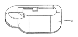
Fig. 2 is the perspective view according to the conveyer device of embodiment of the present invention.
Fig. 3 is durable components and the perspective view of jettisonable parts of the conveyer device of Fig. 2, and wherein durable components and jettisonable parts are separately.
Fig. 4 is the schematic sectional view according to the disposable housing parts of the conveyer device of embodiment of the present invention.
Fig. 5 is the side view of disposable housing parts of the embodiment of Fig. 4.
Fig. 6 is the schematic sectional view according to the durable housing of the conveyer device of embodiment of the present invention.
Fig. 7 is the side schematic sectional view of the durable housing of Fig. 6.
Fig. 8 shows the pump installation of another embodiment and the sketch map of liquid reservoir according to the present invention.
Fig. 9 shows the pump installation of another embodiment and the sketch map of liquid reservoir according to the present invention.
Figure 10 shows according to the present invention the sketch map of the pump installation of an embodiment and liquid reservoir again.
Figure 11 shows the side partial section according to the piston of the pump installation of Fig. 8 of embodiment of the present invention.
The perspective view of the rotating hook bobbin case of the pump installation of Figure 12 demonstration Figure 10 according to the embodiment of the present invention.
Figure 13 a to Figure 15 b shows the side cross-sectional views of the pump installation of Figure 10 in filling position, shuttle back and forth position and distribution locations respectively.
Figure 16 and Figure 17 show the side cross-sectional views of the pump installation of another embodiment according to the present invention separately, and wherein piston lays respectively at extended position and retracted position.
Figure 18 shows the perspective view that can be used on the linear movement motor in another embodiment of the present invention.
Figure 19 shows according to the pump installation of another embodiment of the present invention of the motor that uses Figure 18 and the schematic sectional view of liquid reservoir.
Figure 20 is the perspective view of piston that is used for the embodiment of Figure 19.
Figure 21 shows according to the pump installation of the another embodiment of the present invention of the motor that uses Figure 18 and the schematic sectional view of liquid reservoir.
Figure 22 shows the schematic side elevation of device of durable housing and disposable housing parts of the induction system of the embodiment of the present invention that basis is consistent with the embodiment of Fig. 3.
The schematic side elevation of the durable housing of Figure 23 demonstration induction system of another embodiment and the device of disposable housing parts according to the present invention.
Figure 24 shows the partial exploded view according to the conveyer device of embodiment of the present invention.
Figure 25 shows the schematic plan according to the device of the durable housing of the induction system of embodiment of the present invention and disposable housing parts.
The schematic plan of the durable housing of Figure 26 demonstration induction system of another embodiment and the layout of disposable housing parts according to the present invention.
Figure 27 to Figure 29 shows the perspective view of the connecting device of disposable housing parts and injection site assembly separately.
Figure 30 to Figure 31 shows the perspective view of another connecting device of disposable housing parts and injection site assembly separately.
Figure 32 to Figure 34 shows the perspective view of the another connecting device that is used for disposable housing parts and injection site assembly separately.
The specific embodiment
Present invention relates in general to be used for carrying conveyer device, system and the method for infusion medium (for example medicine) to receptor (for example medical patient user).In concrete embodiment, conveyer device comprises first housing parts and second housing parts (being called durable housing and disposable housing parts in this article respectively), and they are configured to engage one another and connect to realize operation.The disposable housing parts can hold or otherwise support infusion medium liquid reservoir and the miscellaneous part that in operating process, contacts with infusion medium and/or patient user.According to one of them embodiment of describing among this paper, the disposable housing parts also can comprise or otherwise support pump installation.Pump installation is connected to maybe with the fluid flow communication mode can connect liquid reservoir, with from the liquid reservoir withdrawn fluid and/or transport fluid into injection site.
The disposable housing parts can break away from and separate with durable housing from durable housing, make the disposable housing parts after it uses a period of time, are perhaps using once or after the stipulated number, can easily thrown aside.Durable housing break away from from the disposable housing parts and separated after, can engage and functionally be connected to another disposable housing parts (for example new, renovation, the user is that fill, fill in advance, the disposable housing parts of filling or making again once more) so that further operation.Durable housing can be held or otherwise be bearing in the parts that do not contact with infusion medium or patient user in the course of normal operation of conveyer device, includes but not limited to: driving device, drive connector, electronic circuit and in some embodiment, also comprise power supply.
Conveyer device embodiment as herein described can adopt any in the various pump embodiment as herein described, from liquid reservoir, to extract infusion medium and/or infusion medium is transported to injection site.Concrete pump embodiment can be arranged to provide the pump configuration of can mode as herein described operating, and can process with the mode of enough economy, to be included in the disposable housing parts.
Though embodiment of the present invention carries instance to describe at the insulin that this combination is used to treat diabetes, other embodiments of the present invention can be used for carrying other infusion mediums for other purposes to patient user.For example, the medicine that other embodiments of the present invention can be used to carry certain his type includes but not limited to: the medicine that is used to treat cancer, pulmonary disease or the HIV of pain or some type with disease or medical symptom beyond the treatment diabetes.Other embodiments can be used to carry the medium beyond the medicine, include but not limited to: nutrient media (comprising the nutritional supplement), dyestuff or other spike media, saline or other hydration mediums or similar substance.In addition, though embodiment of the present invention is described and is used for carrying or the infusion infusion medium to patient user in this article, other embodiments can be arranged to extract medium from patient user.
And; Though embodiment of the present invention is called jettisonable or durable with the housing parts of disclosed conveyer device; And can be configured to allow the disposable housing parts are thrown aside and replaced with cost-effective mode; But be appreciated that in other embodiments disposable housing parts embodiment as herein described can be re-used and need not be thrown aside.Similarly, if desired, the durable housing embodiment of describing among this paper can be thrown aside after one or many uses.But; Embodiment (for example is configured to allow some parts; Contact infusion medium or patient user's parts in operating process) be contained in can easily derelict first housing parts in; And miscellaneous part (for example; In operating process, do not contact the quite high parts of infusion medium or patient user and alternative costs) can be contained in second housing parts, this second housing parts can that fill, that be pre-charged with, that fill once more, renovation or that make jettisonable first housing parts re-uses again with one or more new, users.
The overview diagram that has shown infusion medium induction system 10 among Fig. 1, wherein this system comprises the conveyer device 12 that is provided with according to the embodiment of the present invention of describing among this paper.System 10 also can comprise by connection and is used for the miscellaneous part of communicating by letter with conveyer device 12, includes but not limited to: perceptron or monitor 14, CCE (CCD) 16 and computer 18.Receptor, emitter or transceiver that each comprised permission in CCD16, perceptron or monitor 14, computer 18 and the conveyer device 12 is communicated by letter with the miscellaneous part of this system.Conveyer device 12 can comprise electronic equipment and the software that is used to analyze the perceptron data and is used for carrying according to the conveying program of data that perceive and/or pre-programmed infusion medium.Can carry out some processing, conveying program memory function and control function through CCD16 and/or computer 18, process by the electronic equipment of more simplifying to allow conveyer device 12.But in other embodiments, system 10 can comprise any one of the system 10 that do not need shown in Fig. 1 or the conveyer device 12 that a plurality of miscellaneous part can be operated.The instance of communication type and/or control performance and device characteristic assembly and/or programs option can find description in following application: on May 27th, 2003 submitted to, application number is 10/445; 477, name is called the U.S. Patent application of " ExternalInfusion Device with Remote Programming, Bolus Estimator and/or VibrationAlarm Capabilities "; Submitted on May 5th, 2003, application number is 10/429,385, name is called the U.S. Patent application of " Handheld Personal Data Assistant (PDA) with a MedicalDevice and Method of Using the Same "; And March 21 calendar year 2001 submit to, application number is 09/813,660, name is called " Control Tabs For Infusion Devices AndMethods Of Using The Same ".All these applications all are incorporated herein by reference.
In the system overview figure of Fig. 1, conveyer device 12 is fixed in patient user 1 with perceptron or monitor 14.In Fig. 1, the position that those parts are fixed in patient user 1 is only as representativeness and the indefiniteness example provides.Conveyer device 12 and perceptron or monitor 14 can be fixed on other positions of patient user 1, and these positions can be decided according to the treatment type that system 10 implements.Other positions like this can include but not limited to other positions on patient's user's body, i.e. position on patient user's clothes, belt, braces, belt, wallet, portable thing or other structures that can be carried by patient user.
Describe in further detail as following, conveyer device 12 has the liquid reservoir of infusion medium and is used for infusion medium (such as but not limited to insulin preparation) is transported to the intravital pump of patient user with controlled way.Control instruction and/or data can be communicated by letter between conveyer device 12, perceptron or monitor 14, CCD16 and computer 18.Conveyer device 12 can be arranged to be fixed in patient user 1 skin with the desired locations of mode on patient user of patch.In these embodiments, ideal situation is that conveyer device 12 has less relatively size to realize comfortable and this device is hidden in the function below the clothes for example.
The application number that the instance of the conveyer device of patch shape was submitted on August 23rd, 2005 is in 11/211,095 the U.S. Patent application description to be arranged, and this application all is incorporated herein by reference.Application number is that the conveyer device described in 11/211,095 the U.S. Patent application adopts and has the liquid reservoir structure of removable plunger, and said removable plunger is used for optionally releasing fluid from liquid reservoir.According to one embodiment of the present invention, the instance of the conveyer device 12 of patch shape is presented among Fig. 2 and Fig. 3, and this embodiment can use for example about Fig. 4 to Fig. 7 or Fig. 8 and pump shown in Figure 9 and described and drive arrangement.Other conveyer device embodiments for example can use about Figure 10 to pump shown in Figure 15 and described and drive arrangement.More another conveyer device embodiment can use Figure 16 for example and shown in Figure 17 and scheme described pump and drive arrangement about these.More another conveyer device embodiment can use Figure 18 for example to shown in Figure 20 and scheme described pump and drive arrangement about these.Conveyer device 12 among Fig. 2 comprises base housing parts 20 and another housing parts 22, and said base housing parts 20 can be disposable in the specified use of one or many back in some embodiment.For convenience's sake, but do not limit, base component 20 is called as disposable housing parts or jettisonable parts in this article, and another housing parts 22 is called as durable housing or durable components in this article.But put down in writing like preceding text, in operation, any one in the housing parts 20 or 22 or both can be thrown aside or re-used according to situation about using.
In illustrational embodiment, the disposable housing parts 20 of conveyer device 12 comprise pedestal 21, this pedestal 21 comprise or otherwise the supporting hold liquid reservoir and pump installation liquid reservoir accommodation section 24.Durable housing 22 can comprise the housing that is fixed on the position of contiguous liquid reservoir accommodation section 24 on the pedestal 21.Durable housing 22 can be held suitable drive mechanism; Electro-motor (not shown among Fig. 2) and drive connector (not shown among Fig. 2) for example; This driving connector is used for when durable housing 22 is connected to disposable housing parts 20, and driving device may be operably coupled to pump so that fluid drives is gone out liquid reservoir.Durable housing 22 also can be held appropriate control electronic component (not shown among Fig. 2), is used for the operation of accessory drive, so that drive out fluid with controlled way from liquid reservoir.Other embodiments can be included in other electronic components in the durable housing 22; Such as but not limited to Communication Electronic Element (not shown among Fig. 2), other elements of the system 10 that is used for showing with perceptron or monitor 14, CCD16, computer 18 and/or Fig. 1 are communicated by letter.
The pedestal 21 of disposable housing parts 20 has bottom surface (face down and get into the page among Fig. 2 and Fig. 3), and this bottom surface is arranged in patient user's desirable fixed-site in patient user's skin.Suitable bonding can be used on the interface between bottom surface and patient user's the skin of pedestal 21, pedestal 21 is adhered to patient user's skin.On the bottom surface of pedestal 21, can be provided with binding agent, and peelable cover layer 23 covers adhesive material.In this way, patient user can peel off cover layer 23 to expose adhesive material, then the binding agent one of pedestal 21 is sidelong on the skin of putting patient user.In other embodiments that are described below; Can be provided with the multi-layer adhesive material on the pedestal 21; Said multi-layer adhesive material and multilamellar covering layer material are alternately; With allow pedestal be fixed in patient user skin, remove from patient user's skin, be fixed in patient user's skin subsequently again, repeatedly re-use or use again realizing.Describe in further detail as following, can use a plurality of alternative layer of adhesive material and peelable cover layer, with the skin that pedestal is used or is administered to patient user again for more than 21 time.
Jettisonable parts 20 can comprise button or other operators 25, are used to operate the pin type that is positioned at liquid reservoir accommodation section 24 and insert device.Alternatively, perhaps in addition, Reference numeral 25 can be represented opening, and outside pin type is inserted device can pass this opening operation.The instance that suitable pin type is inserted device can have description in following application: on August 23rd, 2005 submitted to, application number is 11/211; 095 U.S. Patent application; And on August 23rd, 2006 submit to, application number is 60/839; 840, name is called " Infusion MediumDelivery Device, System And Method With Needle Inserter And Needle InserterDevice And Method " (agent docket is 047711.0384) U.S. Provisional Patent Application.These two applications all are incorporated herein by reference.Other pin type/sleeve pipe is inserted instrument and can be used to (or be modified be used for) and insert spicule and/or sleeve pipe; For example: on March 14th, 2003 submitted to, application number is 10/389; 132, name is called that U.S. Patent application and/or the December in 2002 9 days of " Auto Insertion Device For Silhouette Or Similar Products " is that submit to, application number is 10/314,653, name is called the U.S. Patent application of " Insertion Device For Insertion Set and Method of Using the Same ".These two applications all are incorporated herein by reference.Alternatively; The liquid reservoir accommodation section can comprise that the end with hollow pipe is connected to the suitable openings or the port of liquid reservoir; And the other end of hollow pipe is connected to the hollow spicule, is used to pierce through patient user's skin and infusion medium is delivered in patient user's body, for example from liquid reservoir; As submitted on August 23rd, 2005, application number is that 11/211,095 U.S. Patent application is described about Fig. 2.
The durable housing 22 of conveyer device 12 comprises the housing of being arranged to cooperate and be fixed in disposable housing parts 20 disposable housing parts 20.Durable housing 22 and disposable housing parts 20 can be provided with groove, recess, projection or other suitable components of correspondingly-shaped; Make through with the mode known in the mechanical field with these two partially manual allow by forcing together with these two parts easily interconnection with break off (for example, through friction connect, be fastened and connected, flexibility or movably interlocking member or other suitable connecting devices).In a similar fashion, through manually applying enough power so that durable housing 22 and jettisonable parts 20 are triped each other, can these two parts are separated from one another.In other embodiments; Suitable sealing member; For example lip ring can be placed along the peripheral edge of disposable housing parts 20 and/or durable housing 22, and liquid is close between jettisonable parts 20 and durable components 22, to provide, gastight or air-locked sealing.
Disposable housing parts 20 and/or durable housing 22 can comprise the inside perceptron (not shown at Fig. 2 and Fig. 3) that is used for being connected to patient user; For example; When disposable housing parts 20 were fixed in patient user's skin, said inner perceptron was connected to patient user through the spicule (not shown at Fig. 2 and Fig. 3) that is used for piercing through patient user's skin.In this embodiment, in pedestal 21, can form suitable hole (not shown in Fig. 2 and Fig. 3), when piercing through patient user's skin, allow perceptron spicule process to extend at the perceptron spicule.Alternatively; As submitted on August 23rd, 2005, application number is 11/211; 095, name is called in the U.S. Patent application of " Infusion Device And Method With DisposablePortion " describedly about Fig. 2, and the durable housing 20 of conveyer device 12 can be connected to outside perceptron 14 through the perceptron lead.Perceptron can comprise any suitable biological sensing device, and this depends on the therapeutic properties of conveyer device 12 administrations.For example, insulin is being flowed under diabetics user's the situation, perceptron 14 can comprise the blood glucose perceptron.Alternatively, perhaps in addition, in conveyer device 12 or on the conveyer device 12, can comprise one or more environmental perception devices, be used for one or more ambient conditions of perception.In other selectable scheme, perceptron can be comprised as the part of infusion cannula and/or spicule or at the side of infusion cannula and/or spicule.For example submitted on June 8th, 2005, application number is 11/149,119, name is called shown in the U.S. Patent application of " Dual Insertion Set ", this application all is incorporated herein by reference.
As stated, separate with durable components through the jettisonable parts with conveyer device 12, the jettisonable parts can be disposed on the jettisonable parts 20, and durable components can be disposed in the separable durable components 22.Under this situation, after the use of conveyer device 12 once (or stipulated number), jettisonable parts 20 can separate with durable components 22, make can suitable manner to throw aside jettisonable parts 20.Subsequently, that durable components 22 can cooperate is new (untapped, that the user fills, that fill in advance, that fill once more, renovation or make) again jettisonable parts 20 are to carry out further conveying operations to patient user.Through liquid reservoir 26 being changed and being replaced liquid reservoirs 26 with the different liquid reservoirs that contain any different pharmaceutical; For example combination of Amilyn, GLP-1, Byetta, Peptide C, insulin photosensitizer, medicine (have or do not have insulin) or similar medicine also provide the selection that changes drug conveying for the user.Alternatively, the replaceable dissimilar insulin of user (for example, long lasting, quick-acting or similarly) or use different concentration (U50, U100, U200, U400 or similar concentration).
Be presented among Fig. 4 to Fig. 7 according to the disposable housing parts 20 of the conveyer device 12 of embodiment of the present invention and the example of durable housing 22; Wherein Fig. 4 and Fig. 5 show the vertical view and the side view of disposable housing parts 20 respectively, and Fig. 6 and Fig. 7 show the vertical view and the side cross-sectional views of durable housing 22.With reference to figure 4, as stated, disposable housing parts 20 comprise base component 21 and liquid reservoir accommodation section 24.With reference to figure 4 to Fig. 7; Durable housing 22 is configured to manually be placed on the position of the liquid reservoir accommodation section 24 of contiguous disposable housing parts 20 on the base component 21; And be configured to engage and be connected to disposable housing parts 20, also can optionally separate with disposable housing parts 20 through manual force with disposable housing parts 20.Be described below, when durable housing 22 engaged with disposable housing parts 20 and is connected, the driving device in the durable housing 22 was arranged to form being connected of operability with the pump installation that is positioned at disposable housing parts 20.
Liquid reservoir 26 is positioned at liquid reservoir accommodation section 24.Liquid reservoir 26 can comprise the container with the internal capacity that is used to hold fluid infusion medium (such as but not limited to insulin preparation).Liquid reservoir 26 can be processed with the suitable compatible material of infusion medium by any, includes but not limited to: suitable metal, plastics, pottery, glass, composite or similar material.For example; Liquid reservoir 26 can be formed by the plastic material that is called as TOPAS (trade mark of the Ticona of subsidiary of CelaneseCorporation); For example; This material was submitted on April 5th, 2005, application number is 11/100,188, publication number is in 2005/0197626 the U.S. Patent application description to be arranged, and this application all is incorporated herein by reference.
Liquid reservoir 26 can be supported by the liquid reservoir accommodation section 24 of disposable housing parts 20 in any suitable manner.For example, liquid reservoir 26 can be supported on the surface of pedestal 21 and by one or more projections, wall or other surfaces and remain on the appropriate location.In some embodiments, can be arranged to relative disposable housing parts 20 be movably with interchangeable to liquid reservoir 26.In other embodiments, liquid reservoir 26 can attempt to stop the mode of removing liquid reservoir 26 from disposable housing parts 20 to be fixed in disposable housing parts 20.For example, can use pedestal 21 or other structure of adhesive material with surface adhesion to the disposable housing parts 20 of liquid reservoir 26.In other embodiments; Can be provided with the multi-layer adhesive material on liquid reservoir 26 or the pedestal 21; Replace with the multilamellar covering layer material; With permission liquid reservoir is fixed in pedestal, removes from pedestal, be fixed in pedestal subsequently again and perhaps replaced to be fixed in pedestal, to realize liquid reservoir replacement, filling or other maintenances once more by another liquid reservoir.
In more another other embodiments, liquid reservoir 26 can with liquid reservoir accommodation section 24 monolithic moldings, for example, as the hollow chamber in the solid section that is located at liquid reservoir accommodation section 24.In this embodiment; The hollow of liquid reservoir accommodation section 24 can plate or serve as a contrast suitable metal, plastics, TOPAS plastics (subsidiary of Celanese Corporation, the trade mark of Ticona), pottery, glass, composite or materials similar in another way.Alternatively, perhaps in addition, accommodation section 24 itself can be processed by suitable metal, plastics, TOPAS plastics (trade mark of the Ticona of subsidiary of Celanese Corporation), pottery, glass, composite or similar material.
Liquid reservoir 26 has the port of export 30, and being contained in liquid reservoir 26 inner infusion mediums can be delivered to outside the liquid reservoir through the port of export 30.30 pairs of liquid reservoirs of the port of export 26 are inner open, and can comprise suitable pipe connecting structure, and this pipe connecting structure is used for the mode of fluid flow communication fluid conduit systems 32 being connected with the port of export.This syndeton can comprise that optionally (perhaps in some embodiments permanently) is connected to liquid reservoir 26 so that any suitable syndeton with the inner fluid flow communication of liquid reservoir 26 to be provided.For example, but this syndeton can concur with the diaphragm that is positioned at the liquid reservoir port of export.In this embodiment, syndeton can comprise typical Luer type adapter, and this connection device is useful on the lid structure of the port of export of admitting liquid reservoir and the membranous hollow spicule of the port of export of the liquid reservoir 26 that is used for puncturing.August 23 submitted to such as but not limited to the liquid reservoir adapter 86:2006 described in the following application, application number is 60/839; 840, name is called the U.S. Patent application of " Infusion Medium Delivery Device, System And MethodWith Needle Inserter And Needle Inserter Device And Method " (agent docket is 047711.0384).This application all is incorporated herein by reference.Other instances of spicule/barrier film adapter can be that submit to December in 2003 22 days, application number is 10/328,393, name is called in the U.S. Patent application of " Reservoir Connector " and finds, and this application all is incorporated herein by reference.In other optional embodiments, can use no barrier film adapter, for example Luer lock or similar adapter.Conduit 32 can comprise any suitable structure that fluid flow passages is provided, such as but not limited to: by the tubular conduit that any suitable material is processed, said material includes but not limited to: silicones or other plastics, metal, pottery or composite.
The first end of conduit 32 is connected with liquid reservoir or can be connected with liquid reservoir through above-mentioned liquid reservoir syndeton.The second end of conduit 32 is connected with the arrival end 33 of pump installation 34 with the fluid flow communication mode.Pump installation 34 has with the fluid flow communication mode and the port of export 35 that second conduit 36 is connected, and is used to transport fluid into the delivery site or the injection site 38 that are positioned on the disposable housing parts 20.Injection site 38 can comprise that inserting mechanism is connected with second conduit 36 with the mode with fluid flow communication of also auxiliary spicule or sleeve pipe in auxiliary spicule or the sleeve pipe insertion patient user body.This instance that inserts mechanism that is structured in the conveyer device has description in following application: on August 23rd, 2005 submitted to, application number is 11/211; 095, name be called submit in U.S. Patent application and on August 23rd, 2006 of " Infusion Device And Method With Disposable Portion ", application number is 60/839; 840, name is called the U.S. Patent application (every has all transferred assignee of the present invention) of " Infusion MediumDelivery Device, System And Method With Needle Inserter And Needle InserterDevice And Method " (agent docket is 047711.0384).All these applications all are incorporated herein by reference.Other pin type/sleeve pipe is inserted instrument and can be used to (or be modified be used for) and insert spicule and/or sleeve pipe; For example submitted on March 14th, 2003, application number is 10/389; 132, name is called that U.S. Patent application and/or the December in 2002 9 days of " Auto Insertion Device ForSilhouette Or Similar Products " is that submit to, application number is 10/314; 653, name is called the instance in the U.S. Patent application of " Insertion Device For Insertion Set and Method ofUsing the Same ", and these two applications all are incorporated herein by reference.
(or between arrival end 33 of first conduit 32 and liquid reservoir 26 or pump installation 34) can be provided with first valve 40 in first conduit 32, is used for the single direction of fluid flow restriction at 34 the arrival end 33 from liquid reservoir 26 to pump installation.(or between port of export 35 of second conduit 36 and injection site 38 or pump installation 34) can be provided with second valve 42 in second conduit 36, is used for fluid flow restriction in the single direction from the port of export 35 of pump installation 34 to injection site 38.Any suitable one-way valve structures all can be used for valve 40 and 42.
The illustrative embodiments of the pump installation 34 among Fig. 4 comprises pump chambers 44 and the moveable piston with internal capacity 45, and said moveable piston has piston head 46 that is positioned at pump chambers 44 and the axis of the piston 50 that stretches out from piston head.Piston head 46 can from retracted position (as shown in Figure 4) by the directional selectivity of arrow 48 move to moving position, to reduce the volume of chamber 44 in the part of the port of export one side of piston head 46.Piston head 46 also can be from moving position towards moving to retracted position (as shown in Figure 4) with arrow 48 opposite directions, to increase the volume of chamber 44 in the part of the port of export one side of piston head 46.
Push pedal 52 can be positioned at second chamber 54, and this second chamber 54 separates with piston chamber 44 but is connected with piston chamber 44 through channel part 56.Channel part 56 can comprise the hollow tubular structure with internal path, and the axis of the piston 50 extends through this path.One or more sealing members 58 can be positioned at internal path or contiguous this internal path of channel part 56, such as but not limited to: one or more O-ring packings or similar sealing member are used to stop fluid to pass through channel part 56.Sealing member 58 can be processed by any suitable encapsulant, includes but not limited to: plastics, rubber, silicones, metal, pottery or composite.
Biasing member 60 functionally is connected to piston (for example through functionally being connected with push pedal 52), so that piston is applied biasing force, is used for linear direction (with the arrow 48 in the opposite direction) propelling piston along axle A.In the embodiment of Fig. 4, biasing member 60 comprises longitudinal axis A and the helical spring co-axial with it around the axis of the piston 50 that is arranged in second chamber 54.The helical spring biasing member 60 of Fig. 4 has near an end of second chamber, 54 inwalls with near the other end of the first surface of push pedal 52.Helical spring biasing member 60 is configured to by the state of part compression, thus with arrow 48 direction in the opposite direction to push pedal 52 application of forces.The first surface of push pedal 52 can have annular groove, and an end of helical spring biasing member 60 can reside in the annular groove, to help keeping helical spring biasing member 60 in place.The helical spring biasing member near the surface of second chamber, 54 inwalls similar annular groove can be set, the other end of helical spring biasing member can reside in the annular groove.
In one embodiment, each in the pump chambers 44 and second chamber 54 all has and is roughly columniform main body, and this main body has hollow bulb.In such embodiment, channel part 56 can have between the pump chambers 44 and second chamber 54 the columniform hollow bulb that is roughly that extends, and channel part 56 has and is roughly columniform internal capacity.In addition; In such embodiment; Each comprised discoid component in piston head 46 and the push pedal 52, and the axis of the piston 50 can comprise cylindrical member, each all has said discoid component and said cylindrical member and is roughly circular cross section (perpendicular to axle A intercepting).Yet, in other embodiments, can use this structure member with other suitable shapes.Pump chambers 44, second chamber 54 and channel part 56 can have one overall structure.In selectable embodiment, pump chambers 44, second chamber 54 and channel part 56 can be made up of with the interconnection separate part together of fixed relation one or more.Pump chambers 44, second chamber 54 and channel part 56 can be processed by the suitable material of any rigidity, and said material includes but not limited to: metal, plastics, pottery, composite or similar material.In one embodiment, second chamber 54 can be in aggregates with the shell structure of the liquid reservoir accommodation section 24 that forms disposable housing parts 20.The shell structure of liquid reservoir accommodation section 24 can limit internal capacity (being used to hold the parts of liquid reservoir 26, conduit 32 and 36, injection site 38 and the parts of pump installation 34); Needle injector is before the operation of injection site; This internal capacity is sealed by other hermetically-sealed constructions in the wall of shell structure, sealing member 58 and barrier film or the delivery site 38, thereby isolates with external environment condition.
The liquid reservoir accommodation section 24 of disposable housing parts 20 has sidepiece or wall 66, and this sidepiece or wall 66 have opening (this opening can be recess) 68, can act on push pedal 52 through opening 68.For example, the second surface of push pedal 52 (second surface towards direction and first surface towards in the opposite direction, helical spring biasing member 60 is near said first surface) can expose and towards by the outside direction of opening 68 through opening 68.Be described below; Push pedal 52 is arranged to: when durable housing 22 and disposable housing parts 20 for realizing operation and engage and when linking together, push pedal 52 engages (or otherwise being applied) with the part of driving connector on being supported in durable housing 22.
As stated, durable housing 22 is configured to engage with disposable housing parts 20 and is connected, also can make durable housing 22 with 20 disconnections of disposable housing parts and separate through applying enough manual force.For disposable housing parts and durable housing, can use any suitable syndeton, include but not limited to: the pieceable member that is clasped, frictional fit member, flexible or movably interlocking member or similarly syndeton.In the embodiment shown in Fig. 4 to Fig. 6, syndeton comprises the pair of engaging ratchet 74 that stretches out from the wall 66 of the liquid reservoir accommodation section 24 of disposable housing parts 20, and the receptacle 76 of a pair of respective shapes on the wall 70 of durable housing 22.Each engagement pawl 74 is configured to: when durable housing 22 and disposable housing parts 20 when bonding station aligns; Each engagement pawl 74 can fit in one of them receptacle 76 that is associated, thereby durable housing 22 and disposable housing parts 20 are linked together.
Each engagement pawl 74 can comprise the structure of stretching out from wall 66, and this structure has braking surface 78, is used for when engagement pawl 74 is inserted in its related receptacles 76, engaging with the corresponding braking surface 79 of receptacle 76.The braking surface 78 that is in engagement state stops separating of durable housing 22 and disposable housing parts 20 with braking surface 79, only if it is applied enough separating forces.Preferably; The relative flexibility of ratchet 74 and/or receptacle 76 and elasticity allow durable housing 22 and disposable housing parts 20 to keep interconnection, only if on detaching direction, apply enough manual force (for example with respect to the direction of durable housing along arrow 48 the disposable housing parts are applied power and/or with respect to disposable housing parts edge and arrow 48 rightabouts durable housing applied power).Enough power can cause ratchet 74 and/or receptacle 76 elastic bendings; Be enough to allow the braking surface 78 of each ratchet 74 to run over the braking surface 79 of its related receptacle; Thereby allow ratchet 74 to withdraw from from receptacle 76, jettisonable parts 20 separate with durable components 22 simultaneously.
Each ratchet 74 can comprise that angled or curved surface (surface is angled or its tangent line is not parallel or be not orthogonal to the outer surface of wall 66) is so that ratchet 74 inserts receptacles 76.Have like function described herein thereby ratchet 74 can be processed by the material with enough rigidity and flexibility, this material includes but not limited to: metal, plastics, composite or similar material.Ratchet 74 can be by processing with wall 66 identical materials of disposable housing parts 22, and ratchet 74 can be in aggregates with the wall 66 of disposable housing parts 22.In other embodiments, ratchet 74 can separate formation with the disposable housing parts, and ratchet 74 is connected with wall 66 then.Though illustrated embodiment has only shown a pair of ratchet 74 and a pair of corresponding receptacle 76, other embodiments can adopt single-pawl and single related receptacle, or more than two ratchet and related receptacle more than two.In addition; Though this embodiment has shown ratchet 74 and has been positioned on the wall 66 of disposable housing parts 20; And shown that receptacle 76 is positioned on the wall 70 of durable housing 22; But other some embodiments can be provided with one or more ratchets on the wall 70 of durable housing 22, and on the wall 66 of disposable housing parts 20, the receptacle of one or more associations are set.Other embodiment can be employed in the various combinations that one or more ratchets and related receptacle are set on each of wall 66 and wall 70.
Durable housing 22 comprises shell structure, and this shell structure has internal capacity 80.Driving device 82 is supported in the internal capacity of durable housing 22, and functionally is connected with driving shaft 84 through syndeton 86.Driving device 82 for example can include, but are not limited to: motor or be used for electric energy is changed into other devices of rotation.This driving device can include but not limited to: direct current generator, flat board or minor axis type direct current generator, servomotor, stepper motor, electronically commutated motor, the piezoelectric actuated motor of rotation, have or do not have escape wheel the curved tool of piezoelectric actuated or thermal actuation, have or do not have the electric drive solenoid of escape wheel or have or do not have the shape memory allow wires of escape wheel.Have the various instances that the escape wheel of curved tool, solenoid, shape memory allow wires or like arranges description is arranged in following application: on August 23rd, 2006 submitted to, application number is 60/839,822, name is called the U.S. Patent application of " Infusion Medium DeliveryDevice And Method For Driving Plunger In Reservoir " (agent docket is 047711.0382).This application all is incorporated herein by reference.Other instances of shape memory allow wires drive system can have description in following application: the day for announcing is that April 23, application number in 2002 are 6; 375; 638, name be called submit in United States Patent (USP) and on JIUYUE 19th, 2005 of " Incremental Motion Pump Mechanisms Drivenby Shape Memory Alloy Wire or the Like ", application number is 11/230,142, name is called the U.S. Patent application of " SMA Wire Driven Positive DisplacementMicroPump With Pulsatile Output ".These two patent documentations all are incorporated herein by reference.
In some other embodiment, driving device 82 can comprise the device that electric energy is converted into linear movement, and this device includes but not limited to: piezoelectric actuated solenoid or curved tool, thermal actuation solenoid or curved tool and electric power activate spiral piping arrangement.In the embodiment of these linear movement driving devices, syndeton 86 can comprise any suitable gear, gear transmission chain, band, axle or other connecting devices, and said device converts the linear movement of driving device to the linear movement of driving shaft 84.In other the embodiment of linear movement driving device, the linear movement driving device can directly be connected (or driving shaft 84 can be the part of linear movement driving device, for example be solenoidal driving shaft 84) with driving shaft 84.
Driving device 82 is connected with the durable housing that is supported in conveyer device 22 interior control circuits, is used for according to the infusion conveying program of expectation or the operation of standard accessory drive.Conveying program or standard can be stored in the suitable electronic storage medium (not shown) that places in the durable housing 22 and/or can send conveyer device 12 from other sources to, and said other sources for example are CCD16 or computer 18 (as shown in fig. 1).In these embodiments, conveying program or standard can be adopted with the operation according to said conveying program or standard accessory drive 82 by the control circuit.Alternatively or in addition; Control circuit may command driving device 82 response delivery requirements control signals are carried the infusion medium of one or more discrete magnitudes, the generation or be sent to device 12 from other sources (as shown in fig. 1) of for example CCD16 or computer 18 in device 12 of this delivery requirements control signal.
Above-mentioned two applications all are incorporated herein by reference.
Above-mentioned driving device 82, syndeton 86, control circuit, other electronic circuits and power supply 98 place in the internal capacity 80 of durable housing 22.As stated, driving shaft 84 extends through the opening in the wall 70 of durable housing 22.In order to protect those electric parts and mechanical part to avoid the influence of some environmental aspect (such as but not limited to humidity, air, biological fluid or medical fluid), the internal capacity 80 of durable components 22 can be isolated by following structure and sealing member and external environment condition suitably: by the shell structure that forms durable components 22 with by in the opening in wall 70 or one or more sealing members 99 of being provided with around driving shaft 84 of the opening in the adjacent wall 70.Sealing member 99 can include but not limited to: one or more O-ring packings or similar sealing member.Sealing member 99 can be processed by any suitable encapsulant, and this material includes but not limited to: plastics, rubber, silicones, metal, pottery or composite.
Therefore, the conveyer device 12 of Fig. 4 to Fig. 6 comprises and is used to the durable housing 22 that supports the disposable housing parts 20 of liquid reservoir 26, pump installation 34 and above-mentioned miscellaneous part and be used for supporting driving device 82, driving shaft 84, syndeton 86 and electronic equipment (this electronic equipment also can comprise power supply) 98.In order to operate conveyer device 12, can fill suitable infusion medium in the liquid reservoir in disposable housing parts 20.Disposable housing parts 20 can be fixed in patient user's skin (before filling liquid reservoir or after it) by mode mentioned above.Needle injector be can operate with skin, and hollow needle or sleeve pipe and conduit 36 connected with the mode of fluid flow communication with hollow spicule or sleeve pipe insertion patient user.
Can manually durable housing 22 be alignd with disposable housing parts 20 with the described mode of preceding text; And engage with is connected (before the disposable housing parts are fixed in patient user's skin or after, and before needle injector work perhaps after).Through durable housing 22 being engaged with disposable housing parts 20 and being connected, place near push pedal 52 or contiguous push pedal 52 end of driving shaft 84 (end relative with the end that is connected to driving cam 90).For example; When durable housing 22 and disposable housing parts 20 align with joint and are connected; In the opening in the wall 66 of the liquid reservoir accommodation section 24 of driving shaft 84 extensible entering disposable housing parts 20, and contact push pedal 52 faces outer surface or resides in the position that contiguous push pedal 52 faces outer surface.
In case disposable housing parts 20 engage with durable housing 22 and link together; Driving device 82 can optionally be activated by control circuit electronic equipment electric control that provides and the electric energy that power supply 98 provides, thereby roughly is linear directions (corresponding to the direction of arrow 48 and opposite direction) with the optionally mobile driving shaft 84 of the mode that moves back and forth along two as described above.For example, driving device 82 can be controlled to optionally make driven wheel 92 and driving cam 90 rotation axis 94 that rotates on first direction, optionally to rotate.Along with driving cam 90 rotates, driving shaft moves along the linear direction of arrow 48 in one direction, moves in the opposite direction then.Alternatively; Rotate then rotation in the opposite direction in one direction through control driven wheel 92 and driving cam 90; For example, drive then driving in the opposite direction in one direction, can drive driving shaft 82 with the mode of go-and-return line property motion through accessory drive.
When on the direction of arrow 48, driving driving shaft 84; The extension end of driving shaft 84 and push pedal 52 connect on the direction that is incorporated in arrow 48 push pedal 52 application of forces, on the direction of arrow 48, move push pedal 52 thereby this power is enough to resist the power of helical spring biasing member 60.Along with the direction of push pedal 52 with arrow 48 moves, the axis of the piston 50 and piston head 46 move to moving position with the direction of arrow 48 from retracted position (as shown in Figure 4).Along with piston head 46 moves towards moving position, piston chamber 44 is arranged in the volume reducing of the part of piston head 46 1 sides (direction upper piston head 46 left sides that Fig. 4 shows).Because increasing to push fluid, the minimizing of this partial volume in the piston chamber 44, the pressure in this part arrive injection site 38 through the port of export 35, conduit 36 and check valve 42.
Select amount that driving shaft 84 moves on the direction of arrow 48 with from retracted position (as shown in Figure 4) mobile piston head.In case piston head 46 reaches its moving position, driving shaft 84 also just reaches the solstics of on arrow 48 directions, moving.After this, along with driving device 82 continues to apply driving force, driving shaft 84 with the direction in the opposite direction of arrow 48 on move.Along with driving shaft 84 edges and arrow 48 directions in the opposite direction move; Under the effect of the power of helical spring biasing member 60, push pedal 52, piston, the axis of the piston 50 and piston head 46 also with arrow 48 direction in the opposite direction on move to retracted position (as shown in Figure 4).
Along with piston head 46 with arrow 48 direction in the opposite direction on move to its retracted position from its moving position, be arranged in part volume gain of piston head 46 1 sides (direction piston head shown in Figure 4 46 left sides) in the piston chamber 44.Volume gain along with this part of piston chamber 44, the pressure in this partial volume reduces so that fluid is extracted out from liquid reservoir 26 fully, gets into through conduit 32, check valve 40 and arrival end 33 in the volume of this part of piston chamber 44.In this way, the part that is arranged in piston head 46 1 sides (direction piston head shown in Figure 4 46 left sides) in piston chamber is filled infusion medium, is used for piston head 46 another stroke on the direction of arrow 48.Therefore; Can be by the motion pump device 34 of driving shaft 84 so that infusion medium be pushed into injection site 38 effectively from piston chamber 44, and can by the backhaul power of biasing member 60 come pump device 34 with from liquid reservoir 26 with infusion medium suction piston chamber 44.Control circuit can be according to predetermined conveying standard accessory drive 82, so that an amount of infusion medium is optionally flowed to patient user through injection site.Carry the standard can be according to following information design: the volume of the piston chamber of knowing in advance 44 with know in advance for piston head 46 each stroke from the retracted position to the moving position, be delivered to the volume of the infusion medium of injection site 38 through the port of export 35 and conduit 36.
Before initial aspiration procedure; Can fill in piston chamber 44 in advance; For example, another time period through before the skin that in manufacturing, assembling process or at jettisonable parts, is fixed in patient user, be pre-charged with piston chamber 44 with infusion medium with conveyer device; Through be fixed in before the patient user or after through fill port (not shown) filling piston chamber 44; Perhaps before injection site 38 starts needle injector, so that the one or more strokes of piston head 36 operations, be enough to from the level of liquid reservoir through arrival end 33 withdrawn fluid thereby the pressure in the piston chamber is reduced to through the operation driving device.In more another embodiment; Can in piston chamber 44, be provided with and fill in port; Wherein this is filled in port and can comprise and allow air to overflow, but stops infused fluid to spill piston chamber 44 and stop the said air check valve (not shown) of air admission piston chamber 44.In these embodiments, fill in port and can use and allow circulation of air but stop current materials logical or other liquid communication to cover.This permission gas stream but stop the instance of fluidic structure can in following application, find description: December in 2003 22 days is that submit to, application number is 10/328; 393, name is called the U.S. Patent application of " Reservoir Connector "; And on October 31st, 2003 submit to, application number is 10/699,429, name be called " External InfusionDevice with a Vented Housing " and U.S. Patent application.These two applications all are incorporated herein by reference.
The embodiment that in Fig. 4 to Fig. 6, shows adopts biasing member 60, is used for push pedal 52 application of forces so that retracted position (as shown in Figure 4) is returned in push pedal 52.In these embodiments, driving shaft 84 can be arranged to engage and near push pedal 52, thereby promotes push pedal 52 along the direction of arrow 48; And arrive when replying positions when driving driving shaft 84, biasing member 60 pushes back push pedal 52 (edge and arrow 48 in the opposite direction direction) to retracted position.Other some embodiments can adopt the return movement (edge and arrow 48 in the opposite direction direction) of driving shaft 84 so that push pedal 52 is back into retracted position.These embodiments can use suitable syndeton, are used for when durable housing 22 engages with disposable housing parts 20 and is connected, allowing driving shaft 84 optionally to engage with push pedal 52 and being connected.Said syndeton can include but not limited to: pieceable buckle element, frictional fit element, flexible interlocking member or movably interlocking member or similar syndeton.In one embodiment; Be used for driving shaft 84 and push pedal 52 connection structure connecting can be comprised ratchet and related receptacle layout (being similar to above-mentioned ratchet 74 and receptacle 76); Wherein one of ratchet and receptacle are located in the push pedal, and in ratchet and the receptacle another is located on the end of driving shaft 84.
As stated; Embodiment shown in Fig. 4 to Fig. 6 can adopt any in the various suitable drive mechanism, and this suitable drive mechanism includes but not limited to: direct current generator, flat board or minor axis type direct current generator, servomotor, motor, electronically commutated motor, the piezoelectric actuated motor of rotation, have or do not have escape wheel the curved tool of piezoelectric actuated or thermal actuation, have or do not have the electronically actuated solenoid of escape wheel or have or do not have marmem (SMA) line of escape wheel.For example, the linear movement of push pedal 52 can be produced by the SMA line, and this SMA line is such as but not limited to Nitinol (Ni-Ti/naval ordnance laboratory).The Nitinol driver can be located in the durable housing 22 or in the disposable housing parts 20.
For example; In the embodiment of Fig. 8; SMA line 91 is placed in the disposable housing parts 20, and has with push pedal 52 and be connected end 91a of (or be directly connected to the axis of the piston 50 through omitting push pedal 52) and be connected the second end 91b of fixed position with respect to the disposable housing parts.SMA line 91 is arranged to when on the SMA line, applying the suitable electric potential signal, property direction (direction of said SMA line) along the line thus launch on the direction of arrow 48, to promote the axis of the piston 50.Two end 91a of SMA line 91 and 91b are connected with electrical connector element 93 on the disposable housing parts 20 through suitable electric lead 95 and electric lead 97.
Connecting element 93 is configured to when disposable housing parts 20 engage with durable housing 22, is electrically connected with corresponding connecting element 93 ' on the durable housing 22.Connecting element 93 ' is electrically connected with battery (perhaps other suitable power supplys) and control electronic equipment 98; Be used on lead 95 and lead 97, optionally applying electromotive force; Thereby when disposable housing parts 20 engage with durable housing 22, to SMA line options property apply voltage.Because only need being electrically connected to fetch, the SMA line driving device in power supply in the durable housing 22 and the disposable housing parts 20 realizes operation; So housing parts 20 can be closed and seal with housing parts 22 separately, and need not comprise any opening that leads to external environment condition.In other embodiments, the housing parts of sealing can comprise vent, is used for the pressure between the inside and outside environment of balance shell body component.
In the embodiment of Fig. 8; When durable housing 22 engages with disposable housing parts 20; Form electrical connection between connecting element 93 and the connecting element 93 ', thereby battery is connected with lead 97 with the lead that is used for the SMA line 95 with control electronics 98.Applying controlled source signal with control electronic equipment 98 guiding lines 95 with lead 97 from battery causes the SMA line to launch at linear direction.Because the end 91b of SMA line is connected with disposable housing parts 20 with fixed relation, the controlled linear expansion of SMA line causes the second end of SMA line on the direction of arrow 48, optionally to move, thereby on the direction of arrow 48, moves push pedal 52.In this way, but battery and control electronic equipment 98 operating pumps 34 so that fluid is optionally pushed to injection site from pump.
Shown another driving instance that uses the SMA line among Fig. 9, wherein the SMA line places in the durable housing 22.In Fig. 9, SMA line 91 ' has end 91a ' that links to each other with push rod 100 and the second end 91b ' that is connected with durable housing 22 with fixed relationship.Push rod 100 is supported to realize its moving of (direction of arrow 48 and the direction in the opposite direction with arrow 48) on linear direction, for example, and by suitable supporting structure 102 supportings that comprise near the sliding bearing surface of push rod 100.Supporting structure 102 can be the part of durable housing 22 or is attached on the durable housing 22.Push rod 100 is connected with matching element 104, and matching element 104 has can be from the outside approaching match surface of durable housing 22.Biasing member applies backhaul power to matching element 104, and biasing member can comprise the helical spring that is connected between matching element 104 and the supporting structure 102.
In the embodiment of Fig. 9, when durable housing 22 engages with disposable housing parts 20, form mechanical connection between matching element 104 and the connecting axle 50.The controlled source signal that is applied on the SMA line causes the SMA line on linear direction, to launch.Because the end 91b ' of SMA line is connected with durable housing 22 with fixed relationship; The second end that the controlled linear expansion of SMA line causes the SMA line optionally moves on the direction of arrow 48, thus on the direction of arrow 48 mobile putter 100 and matching element 104.In this way, but battery and control electronic equipment 98 operating pumps 34 so that fluid is urged to injection site from pump.
Linear movement pump installation 134 according to another embodiment of the present invention shows in Figure 10 to Figure 15.Can use pump installation 134 to replace above-mentioned linear movement pump installation 34 to the described conveyer device 12 of Fig. 4 to Fig. 7 in the above.Pump installation 134 has traverse mechanism, operates this traverse mechanism through the linear force that applies the linear movement that is used to provide the piston shuttle.
Referring to Figure 10, pump installation 134 operations are with distributing fluids from liquid reservoir 126.Liquid reservoir 126 can place in the disposable housing parts similar with above-mentioned disposable housing parts 20.Above can comprising, liquid reservoir 126 is directed against the liquid reservoir 26 described liquid reservoir structure among Fig. 4 to Fig. 7.Alternatively, liquid reservoir 126 can comprise flexible pouch or container, and this flexible pouch or container have the flexible wall that shrinks from inner outflow of liquid reservoir along with fluid.
In the embodiment of Figure 10 to Figure 15, arrival end 142 and the longitudinal axis A of the port of export 144 around passage 140
1Depart from 180 degree mutually, with respect to the direction of Figure 10 to Figure 15, arrival end 142 upwards and the port of export is downward.Yet, in some other embodiment, arrival end 142 and the port of export 144 can depart from mutually less than or greater than 180 degree, or with respect to the longitudinal axis A of passage 140
1Being aligned property (not departing from).The port of export 144 is connected to and the conduit of injection site with fluid flow communication, for example conduit shown in Fig. 4 36 and injection site 38.
Piston joint 146, piston joint 148 arrange end-to-end, and piston joint 146, piston joint 148 are arranged at least that part is positioned at passage 140, and like this, an end 147 of piston joint 146 is in the face of the end of oppositely facing 149 of piston joint 148.Piston joint 146, piston joint 148 are independent structures main bodys, its link together but relative to each other can passage 140 axially on move.Be provided with and be suitable for allowing piston joint 146 and piston joint 148 relative to each other axially movable syndetons to link together so that piston joint 146, piston are saved 148.An embodiment of this suitable syndeton shows in Figure 11, and this syndeton comprises hollow inner channel 150, and hollow inner channel 150 inside of a piston joint (for example the piston joint 148) therein extends axially.Piston joint 148 is provided with the opening 152 of the inner passage 150 that gets into piston joint 148 towards the end of piston joint 146.The passage 150 of piston joint 148 has stair-stepping inner surface, and it has the first diameter D of adjacent openings 152
1And along axial A
1Opened the second diameter D far away in 152 minutes with opening
2The step that forms braking surface 154 is located at two diameter D of passage 150
1And D
2Between transition position.Said syndeton also comprises extension 156, and the end towards piston joint 148 extends axially extension 156 from piston joint 146.Extension 156 rigidly fixes with respect to piston joint 146.Extension 156 can save 146 integrally formedly as one, whole main body with piston, and perhaps extension 156 can save 146 fens and opens and form and fixedly be fixed in piston joint 146 with piston.Extension 156 extends and passes piston and save opening 152 admission passages 150 in 148 ends to piston joint 148.Extension 156 has end freely, and head 158 is positioned on the said end.Be described below, head 158 is provided with braking surface 160, is used for engage brake face 154.
Get around mouth 152 and/or can be provided with one or more sealing members 159 (including but not limited to O-ring packing), to stop fluid flow communication through opening 152 and admission passage 150 around extension 156.This sealing member 159 can be processed by any suitable encapsulant, and encapsulant includes but not limited to: metal, plastics, silicones, pottery, composite or similar material.Though the syndeton in the embodiment of Figure 11 adopts the passage 150 in the piston joint 148 to save the extension 156 on 146 with piston; But other embodiments can adopt passage 150 and the piston in the piston joint 146 to save the extension on 148, work with said mode.
Said syndeton allows piston joint 146, piston joint 148 relative to each other to move axially, and with the limited distance that is separated from each other, but piston joint 146, piston joint 148 still keep interconnection.Along with one of piston joint 146, piston joint 148 or both move axially with separately piston joint 146 and piston joint 148, between piston joint 146 and piston joint 148 opposed facing separately ends 147 and end 149, form gap or chamber 162.Along with one of piston joint 146, piston joint 148 or both move and separate, the width (in the axial direction) of gap or chamber 162 increases, and engages with the braking surface 154 of the stepped inner surface of passage 150 until the braking surface 160 of head 158.When braking surface 160 engaged with braking surface 154, piston joint 146, the piston joint 148 further relative motion on detaching direction (axially away from each other) was prevented from.On the other hand; Along with one of piston joint 146, piston joint 148 move from the separation point position towards another piston joint; The width of gap or chamber 162 (in the axial direction) reduces, and is in contact with one another until right end 147, the end 149 of opposite face of piston joint 146, piston joint 148.
In operating process, the selectivity operation through driving device (combining the operation of the driving device that Fig. 4 to Fig. 7 describes above being similar to), piston 138 (comprise piston joint 146 and piston joint 148 both) is along axial A
1Move with linear mode.In one embodiment; End 151 with respect to the piston of end 149 joint 148 is arranged to driven shaft (driving shaft of describing about Fig. 4 to Fig. 7 for example 84) effect; Piston is saved 148 application of forces, this power is enough to provide the axially-movable of piston 138 in passage 140.For example; The rotating hook bobbin case 136 and the piston 138 of the pump installation 134 of Figure 10 can be supported in the liquid reservoir accommodation section 24 of disposable housing parts 20 (Fig. 4 and Fig. 5's); To replace above-mentioned pump installation 34; And the openings 68 that the end 151 of above-mentioned piston 138 is arranged through in the wall 66 of disposable housing parts 20 expose, or otherwise are arranged through openings 68 in the wall 66 of disposable housing parts 20 and are applied (end that is similar to above-mentioned push pedal 52 is passed opening 68 and exposed or otherwise pass 84 effects of opening 68 driven shafts).When durable housing 22 engaged with disposable housing parts 20 and is connected, driving shaft 84 was arranged to otherwise save 148 end 151 near piston, or is arranged to end 151 application of forces to piston joint 148.
Driving shaft 84 can be provided with suitable syndeton with the end 151 of piston joint 148, is used for when durable housing 22 engages with disposable housing parts 20 and is connected permission driving shaft 84 and piston and saves 148 end 151 and optionally engage and be connected.Said syndeton can include but not limited to: pieceable buckle element, frictional fit element, flexible interlocking member or movably interlocking member or similar syndeton.In one embodiment; The syndeton that is used to connect the end 151 of driving shaft 84 and piston joint 148 can comprise ratchet and related receptacle layout (being similar to ratchet mentioned above 74 and receptacle 76); Wherein one of ratchet and receptacle are located in the push pedal, and in ratchet and the receptacle another is located on the end of driving shaft 84.
Through the end 151 of driving shaft 84 with piston joint 148 is connected, driving shaft 84 can save 148 application of forces to piston along the direction of arrow 164, and the direction along arrow 166 saves 148 application of forces to piston then, thereby at axial A
1On motion back and forth is provided.Select the length of driving shaft 84 motions and the size of piston joint 146, piston joint 148 and extension 156, thereby, allow the piston joint to move (along with the motion of driving shaft 84) as described about Figure 13 to Figure 15.
Piston 138 (comprising the piston joint 146,148 shown in Figure 13 to Figure 15) can be along axial A
1At least three home positions between along axial A
1Move.These three home positions are called filling position (Figure 13 a-c), the position of shuttling back and forth (Figure 14) and distribution locations (Figure 15 a-b) here.
Before operation beginning (for example, in manufacturing, assembling or installation process), piston 138 can be placed on the initial part of filling position, and (Figure 13 a).Alternatively; Piston 138 can be positioned at another initial position (the for example position shown in Figure 14) before operation, can carry out initial operation to move therefore driving shaft 84 moves to along the direction of arrow 164 piston 138 filling position from said initial position initial part (shown in Figure 13 a) to driving device 82 simultaneously.
Driving force on the piston 138 is applied on the end 151 of piston joint 148 through driving shaft 84.Therefore; If piston joint 146, piston joint 148 are isolating at first; The driving force that on the direction of arrow 164, applies through 84 pairs of pistons ends 151 of driving shaft will at first cause piston joint 148 to move to piston joint 146; And closed gap or chamber 162 contact with 149 with piston joint 148 end face 147 separately until piston joint 146.
Initial (or termination) portion at filling position shown in Figure 13 a; Piston 138 is arranged to the end face 147 of piston joint 146 and the end face 149 neighboring entry ends 144 of piston joint 148, and between the end face 149 of the end face 147 of piston joint 146 and piston joint 148, does not have (perhaps having only minimum) gap.Piston joint 148 can move in the direction of arrow 166 from the initial part of the filling position of Figure 13 a, to open end face 147 and the gap between the end face 149 or the chamber 162 of piston joint.
When gap or chamber 162 and external environment condition isolation, the opening of gap or chamber 162 forms low-voltage space (with respect to the pressure in the liquid reservoir 126) in gap or chamber 162.In one embodiment, the low-voltage space in this gap or the chamber 162 provides enough pressure differentials with respect to the pressure in the liquid reservoir 126, passes through in arrival end 142 inflow gaps or the chamber 162 from liquid reservoir 126 to cause fluid.Through opening clearance or chamber 162, fluid is passed through arrival end 142 suction gaps or chamber 162 from liquid reservoir.Along with piston joint 148 continues to move along the direction of arrow 166; Gap or chamber 162 continue to be widened to the complete filling portion of filling position shown in Figure 13 c, are in complete isolating state (wherein the braking surface 154 of Figure 11 abuts against together with braking surface 160) at this piston joint 146 and piston joint 148.
In the filling position of Figure 13 a to Figure 13 c, piston joint 146 and piston joint 148 be with respect to rotating hook bobbin case 136 location, makes gap or chamber 162 be positioned to arrival end 144 with rotating hook bobbin case 136 with fluid flow communication.In this position, between liquid reservoir 126 inside and gap or chamber 162, fluid flow communication is provided through arrival end 144, flow in gap or the chamber 162 from liquid reservoir to allow infused fluid.Fluid can be in liquid reservoir 126 inflow gaps or chamber 162; For example through opened the power of the pressure differential that produces when forming gap or chamber 162 in 148 minutes at piston joint 146, piston joint; And/or pass through gravity (shown in Figure 13 to Figure 15; Wherein in operating process, gap or chamber 162 are positioned at the below of liquid reservoir 126).Alternatively; Perhaps in addition; Through liquid reservoir 126 pressure inside are arranged to be higher than in gap or the chamber 162 pressure (for example; Through the application of force on the flexible wall of liquid reservoir, and/or with the fluid filled liquid reservoir of pressurization), can provide or strengthen from liquid reservoir 126 to the gap or the fluid of chamber 162 stream.
From the complete filling portion of the filling position of Figure 13 c, driving shaft 84 causes piston 138 (comprising piston joint 146,148) to move along the direction of arrow 166 along further the moving of direction of arrow 166, keeps gap or chamber 162 simultaneously.Along with the direction of piston 138 along arrow 166 moves; Gap or chamber 162 move with the direction of arrow 166; Through the position between the arrival end 142 and the port of export 144 to the conveying shown in Figure 14 or the position of shuttling back and forth, gap or chamber 162 align with the port of export 144 in this conveying or the position of shuttling back and forth.Can select the entire motion stroke of driving shaft 84, make that piston joint 146 is corresponding with the position of piston joint 148 among terminal point and Figure 14 of the movement travel of driving shaft 84 on the direction of arrow 166 with the direction of arrow 166.Similarly, can select the entire motion stroke of driving shaft 84 on the direction of arrow 164, make that the terminal point of the movement travel of driving shaft 84 on the direction of arrow 164 is corresponding with the position of piston joint 146 and 148 among Figure 13 a.
At the terminal point of driving shaft 84 along the entire motion stroke of the direction of arrow 166, driving shaft 84 beginning is moved on the direction of arrow 164 (with arrow 166 in the opposite direction) backward.Through allow driving shaft 84 in the direction mobile phase of arrow 164 to less distance; Shown in Figure 15 a; Piston joint 148 moves with rotating hook bobbin case 136 with respect to piston joint 146 on the direction of arrow 164, thus begin with fluid from the gap or chamber 162 be assigned in the port of export 144.The further motion of driving shaft on arrow 164 directions causes piston joint 148 on the direction of arrow 166, to move, up to the end face 147 of piston joint 146 and piston joint 148 and end face 149 shown in Figure 15 b mutually near.
In the complete dispenser of distribution locations (Figure 15 b), through piston joint 146 and piston joint 148 further are driven into together, the pressure in gap or the chamber 162 increase, thereby infusion medium is released gap or chamber 162 and pushed conduit 36.For example, in case piston 138 arrives as upper/lower positions: this position gap or chamber 162 aligns with the port of export 144 and with its fluid flow communication, (Figure 14) driving shaft 84 can be on the direction of arrow 164 saves 148 end face 151 application of forces (Figure 15 a to Figure 15 b) to piston.This power causes piston joint 148 on the direction of arrow 164, to move axially with rotating hook bobbin case 136 with respect to piston joint 146, until the end face 149 (Figure 11) of the end face 147 of piston joint 146 and piston joint 148 mutually near.Along with piston joint 148 moves to piston joint 146, the volume reducing of gap or chamber 162 causes the infusion medium in gap or the chamber to be extruded gap or chamber, and is assigned in the conduit 36 through the port of export 144.
Piston joint 146 can be arranged to provide the bi-directional friction power with the inner surface of the piston channel 140 of cylinder 136, and this bi-directional friction power is greater than the frictional force of the piston element 148 in the cylinder 136.Filling stroke directions 166, piston joint 146 keeps motionless to open chamber 162 with respect to the motion of piston element 148.On dispense stroke direction 164, the motion that 146 opposings of piston joint are moved with respect to piston joint 148, thus fluid is pushed in the port of export 144 from chamber fully.This bi-directional friction power that is used for piston joint 146 can provide in the following manner: through selecting the shape and/or the outside dimension of piston joint 146; Perhaps save 146 with abuts against plunger through the biasing member that spring-loaded biasing member or other modes are provided; Thereby the suitable frictional engagement with piston channel 140 inner surface is provided, and/or through one or more O-ring packings being set around piston joint 146.
By the structure of Figure 10 to Figure 15, this motion of piston 138 causes piston joint 146, piston joint 148 between rotating hook bobbin case 136 inherent filling positions (Figure 11), the position of shuttling back and forth (Figure 12) and distribution locations (Figure 13), to move and return.This motion of piston joint 146, piston joint 148 causes a certain amount of infusion medium along with moving back and forth of piston 138 is assigned with entering conduit 136 from the port of export 144 at every turn.The amount of the infusion medium that at every turn the moving back and forth of piston 138 distributed depends on the volume of gap or chamber 162, and can be confirmed in advance, and the conveying standard that is used to provide suitable is with the operation of accessory drive 84.Therefore, the pump installation embodiment of Figure 10 to Figure 15 can functionally be connected with the driving shaft of Linear Driving, to allow to carry out with less relatively moving-member and simple relatively structure member the controlled distribution of infusion medium.
The linear movement pump installation 234 of another embodiment shows in Figure 16 and Figure 17 according to the present invention.Pump installation 234 can be positioned at like top liquid reservoir accommodation section 24 to Fig. 2 and the described disposable housing parts 20 of Fig. 3.For example, pump installation 234 can be used on as above in the described conveyer device 12 of Fig. 4 to Fig. 7, to replace above-mentioned linear movement pump installation 34.
In Figure 16 and Figure 17, the pump installation 234 that is operably connected, thus transmit fluid between liquid reservoir 226 in liquid reservoir accommodation section 24 and the injection site 238.For example, but operating pumps device 234 so that the fluid infusion medium is flowed to patient user from liquid reservoir 226 through hollow spicule or sleeve pipe, this hollow spicule or sleeve pipe insert patient user's skins in injection site 238.Pin type is inserted device (not shown in Figure 16 and Figure 17) and can be arranged in injection site 238 and/or as above be directed against opening 25 (or other suitable operators) the operation pin type insertion device that Fig. 2 and Fig. 3 liquid reservoir saidly can pass liquid reservoir accommodation section 24.Above can being similar to injection site 238, liquid reservoir 226 among Figure 16 and Figure 17 is directed against the described liquid reservoir 26 of embodiment and injection site 38 of Fig. 4 to Fig. 7.
In Figure 16 and Figure 17, piston channel element 249 is positioned at housing joint 236 and has the centre gangway that limits piston channel 241 and piston chamber 250.The gap that between the part of the part of piston channel element 249 and housing joint 236, is provided with forms outlet chamber 248.When check valve 252 being set between piston chamber 250 and the outlet chamber 248 being enough to open check valve 252, allow from piston chamber 250 to outlet chamber 248 fluid stream with the fluid pressure in piston chamber 250.
In operating process; Piston 240 moves axially in piston chamber 250, to form low-voltage space along the direction of arrow 243, and the pressure of this low-voltage space is enough to fluid is passed through in arrival end 246, passage 241 and the path 256 sucker chambers 250 from liquid reservoir 226.Thereby the infusion medium from liquid reservoir can get into and be contained in the piston chamber 250, moves up to the direction of piston 240 along arrow 244.In case piston chamber 250 has filled infusion medium fully, piston 240 just moves along the direction of arrow 244, to increase the fluid pressure in the piston chamber 250.In case the fluids in the piston chamber 250 reach enough pressure, check valve 252 just open and chamber 250 in fluid from chamber 250 flows to and injection site 238 is connected with the fluid flow communication mode conduit 236.Above can being similar to injection site 238, conduit 236 is directed against described conduit 36 of Fig. 4 and injection site 38.Check valve 252 allows fluid to flow out and flow out through outlet chamber 248 from piston chamber 250, but stops fluid to flow into piston chamber 250 from outlet chamber 248.
In the embodiment of Figure 16 and Figure 17, check valve 252 comprises the duckbill valve structure that is formed on the piston channel member.Yet other embodiments can adopt other suitable check valve structures.Therefore; As along the direction of arrow 243 and then along the result of the piston stroke of the direction of arrow 244; A certain amount of infusion medium is from liquid reservoir 226 suction pump installations 234; Under the controlled motion of driving device (such as but not limited to above-mentioned driving shaft 84 and driving device 82), be assigned to injection site 238 then through check valve 252.When along the direction of arrow 243 and then when the piston stroke of the direction of arrow 244 is accomplished, can repeat the piston motion so that infusion medium further flows to injection site.
Therefore, can be similar to the operation of the driving shaft 84 on above-mentioned pump installation 34 and the pump installation 134 with the pump installation 234 that can roughly be linearly moving driving shaft 84 operation Figure 16 and Figure 17.In addition; The pump installation 234 of Figure 16 and Figure 17 can be supported by first housing parts (for example the disposable housing parts 20); And driving shaft 84 is supported by second housing parts (for example durable housing 22) with driving device 82, and wherein first housing parts and second housing parts are configured in order to operate optionally engage and break away from each other as stated.
The linear movement pump installation 334 of another embodiment shows in Figure 18 to Figure 20 according to the present invention.The pump installation 334 of Figure 18 to Figure 20 can be positioned at the liquid reservoir accommodation section 24 that as above is directed against Fig. 2 and the described disposable housing parts 20 of Fig. 3.For example, conveyer device 12 can adopt as above about the described pump installation 334 of Fig. 4 to Fig. 7, to replace above-mentioned linear movement pump installation 34 and liquid reservoir 26.
Pump installation 334 adopts miniature piezoelectric actuator or motor; Such as but not limited to the motor that is called Squiggle (SQUIGGLE is the trade mark of New Scale Technologies), described Squiggle motor is produced by the New Scale Technologies company limited of New York Victor.For example the representative of the miniature piezoelectric motors 344 of Squiggle motor shows in Figure 18.Referring to Figure 18, motor 344 comprises supporting structure 345, the plate of for example processing by the suitable material of rigidity, and this rigidity suitable material is such as but not limited to metal, plastics, pottery, glass, composite or similar material.Piezoelectric patches or laminated piezoelectric 346 are supported on a side of support plate 345.Screw rod housing 347 is positioned at the opposite side of piezoelectric patches or laminated piezoelectric 346 with respect to support plate 345.Screw rod housing 347 can include but not limited to: have nut or plate that drive screw 348 extends through opening wherein.Screw rod housing 347 can be processed by the suitable material of rigidity, and this material is such as but not limited to metal, plastics, pottery, glass, composite or similar material.Drive screw 348 with screw thread extends through screw rod housing 347, piezoelectric patches or laminated piezoelectric 346 and motor bearing plate 345, and is arranged to when piezoelectric patches or laminated piezoelectric 346 startups, move and rotate with respect to screw rod housing 347 and motor bearing plate 345 with linear direction (direction of arrow 349).Piezoelectric patches or laminated piezoelectric 346 are connected with control electronic equipment (not shown in Figure 18) with suitable power supply, are used for optionally encouraging piezoelectric patches or laminated piezoelectric 346.Motor 344 can be bearing in the aforesaid durable housing 22.Along with the body vibration of motor 344, screw rod rotates, and generation can accurately control to the linear movement of nano-precision.In one embodiment, motor 344 is set to linear actuators, thereby wherein keeps screw rod to fix and use vibration generation portion to provide power to drive the fluid from liquid reservoir with the piston in the pushing and pressing liquid reservoir.
When durable housing 22 engaged with disposable housing parts 20, the pump installation 334 that is operably connected was with transmitting fluid between liquid reservoir 326 in the liquid reservoir accommodation section 24 of disposable housing parts and the injection site 338 (being similar in above-mentioned injection site 38).Liquid reservoir 326 can comprise that jar type container or other have the suitable containers of internal capacity, and this internal capacity has vertical A
2, piston is A longitudinally
2Move.Pump installation 334 comprises and is positioned at liquid reservoir 326 and can be at vertical A of liquid reservoir 326
2Go up the piston 336 that moves.Piston 336 comprises piston head 341 and the axis of the piston 339.The shape and size of piston head 341 are suitable for flowing with the fluid between the inner surface that stops piston head 341 and liquid reservoir 336 near the inner surface sealing of liquid reservoir 326.Alternatively, perhaps in addition, can be provided with one or more sealing members with the stream of the fluid between the inner surface that stops piston head 341 and liquid reservoir 326 around the peripheral surface of piston head 341.The motion of piston 336 on the direction of arrow 350 makes the volume reducing and the drive fluid of the fluid containment portion 352 of liquid reservoir 326 flow to injection site 338 from liquid reservoir 326.
In the embodiment of Figure 19 and Figure 20; The axis of the piston 339 has half-terete shape and open half-terete hollow area, entangles when this hollow area is provided in durable housing and disposable housing part bonding and holds at least a portion of motor 344 and engage the motor bearing plate 345 of motor 344.Half-terete the axis of the piston 339 can comprise that breach, otch, opening or the similar structure of suitable shape are to hold the part of motor 344, up to holding screw rod housing 347.Other breach, otch or opening can be located on the end face of half-terete the axis of the piston 339 with screw rod housing 347 close match of motor 344; In case motor 344 engages with the axis of the piston 339, but starter motor is to fill in fluid path and motor is located on the axis of the piston 339.
In the embodiment of Figure 19, the startup of motor 344 (through controlled power supply signal optionally being put on piezoelectric patches or laminated piezoelectric 346) causes the relative motion between drive screw 348 and the screw rod housing 347.Through supporting an end of the drive screw 348 that engages with fixed surface 358 (is fixed with respect to durable housing), the relative motion between drive screw 348 and the screw rod housing 347 converts the motion of screw rod housing 347 on the direction of arrow 350 into.Because screw rod housing 347 engages with half-terete the axis of the piston 339, the motion of screw rod housing 347 on arrow 350 directions causes piston 336 to move with the direction of arrow 350.In this way, the controlled activation of piezoelectric patches or laminated piezoelectric 346 controlled motion that piston 336 is provided flow to injection site 338 with drive fluid optionally from liquid reservoir inner 352.The friction free bearing can be located at the bonding station on screw rod 348 and surface 358.Thereby the hollow of half-terete the axis of the piston 339 can manufacture enough greatly to provide the space to avoid to hinder any rotational motion of drive screw 348.
Another embodiment shown in Figure 21 comprises as above to described liquid reservoir 326 of Figure 19 and piston head 341.Yet; As the replacement scheme that adopts half-terete the axis of the piston (as above said) about Figure 19; Embodiment among Figure 21 adopts the drive screw 348 of motor 344 as the axis of the piston; Wherein when durable housing 22 engaged with disposable housing parts 20, an end of drive screw 348 can directly be connected with piston head 341.Alternatively, when durable housing 22 engaged with disposable housing parts 20, extended element can be connected from drive screw 348 extensions and with piston head 341.In the embodiment in Figure 21; The screw rod housing 347 of motor bearing plate 345 and/or motor 344 is fixed in durable housing 22 with fixed relation; For example, through one of screw rod shell 347 of motor support plate 345 and motor 344 or both are connected with the wall 360 of durable housing 22 or the walls 360 in the durable housing 22.In operating process, when suitable power supply signal optionally put on motor 344, drive screw 348 optionally moved on the linear direction of arrow 350, thereby with respect to liquid reservoir 326 mobile piston head 341 optionally.So, the piston head among Figure 21 341 optionally moves to reduce liquid reservoir 326 inner volume 352 and drive fluid and flows to injection site 338 from liquid reservoir 326.
In the above-described embodiment, disposable housing parts (for example, 20 among Fig. 3) are provided with pedestal 21, and said pedestal 21 is through being fixed in patient user's skin such as but not limited to the adhesive material of being located on pedestal 21 bottom surfaces.This is arranged among Figure 18 with the side view schematic representation, and wherein adhesive material 101 is located on the bottom surface (towards the surface of skin) of the pedestal 21 of disposable housing parts 20.Shown in Fig. 2, Fig. 3 and Figure 18, durable housing 22 can be configured to be arranged on the pedestal 21 of disposable housing parts 20 to engage with disposable housing parts 20 and to be connected.In this arrangement, pedestal 21 can be disposed between durable housing 22 and patient user's the skin in operating process, thus in operating process only the pedestal 21 of disposable housing parts keep and patient user's contact skin.
Yet in other embodiments, for example, as shown in Figure 19, durable housing 22 can be arranged to engage one another with parallel layout with disposable housing parts 20.In the parallel layout in Figure 19, durable housing 22 and one of disposable housing parts 20 or both can be provided with have adhesive material 101 pedestal of (and peelable cover layer 23 as shown in Figure 3).
In another embodiment, as represented by Figure 20, perhaps both can be connected with independent base component 21 ' and be detachable durable housing 22 with one of disposable housing parts 20.Suitable syndeton, the for example above-mentioned syndeton that durable housing and disposable housing parts are linked together of being used for can be used for durable housing is connected with base component 21 ' with the disposable housing parts.Independent base component 21 ' can comprise the platy structure of the general flat of being processed by the suitable material of any rigidity, and the material that said rigidity is suitable includes but not limited to: plastics, metal, pottery, composite or similar material.Base component 21 ' has disposable housing parts 20 and durable housing 22 can attach to its surface (surface that makes progress among Figure 20).Base component 21 ' has adhesive material and strippable coverlay can put on its second surface (among Figure 20 downward surface), as stated, is fixed in patient user's skin to allow base component 21 '.
Base component 21 ' can comprise aforesaid pin type insertion device 25.The instance that suitable pin type is inserted device has description in following application: submit on August 23rd, 2005, application number is 11/211,095 U.S. Patent application; And on August 23rd, 2006 submit to, application number is 60/839; 840, name is called the U.S. Patent application of " INFUSION MEDIUM DELIVERY SYSTEM, DEVICE AND METHODWITH NEEDLE INSERTER AND NEEDLE INSERT DEVICE ANDMETHOD " (agent docket is 047711-0384).Each item application in these applications all is incorporated herein by reference.In this embodiment, base component 21 ' can be fixed in patient user's skin.Then, can activate pin type and insert device 25 with skin with hollow spicule or sleeve pipe insertion patient user.Then; After inserting hollow spicule or sleeve pipe; Can durable housing 22 and disposable housing parts 20 be attached to base component 21 ', so that the liquid reservoir in the disposable housing parts 20 and hollow spicule or the sleeve pipe mode with fluid flow communication is coupled together.In one embodiment, durable housing 22 and disposable housing parts 20 are being attached to base component 21 ' before, (for example, with above-described mode) can link together these housing parts.In another embodiment, before durable housing and disposable housing parts are linked together, one of durable housing and disposable housing parts are attached to base component 21 '.In this embodiment; The disposable housing parts are being attached to base component 21 ' (before durable housing and disposable housing parts are linked together or after) afterwards, can activating pin type and insert device hollow spicule or sleeve pipe are inserted patient user's skin.Other pin types/sleeve pipe inserts instrument can be used to (perhaps be modified and be used for) to insert spicule and/or sleeve pipe; For example: on March 14th, 2003 submitted to, application number is No.10/389; 132, name is called the U.S. Patent application of " Auto Insertion Device For Silhouette Or SimilarProducts "; And/or December in 2002 9 days is that submit to, application number is 10/314,653, name is called the U.S. Patent application of " Insertion Device For Insertion Set and Method of Using the Same ".These two applications all are incorporated herein by reference.
Alternatively, Reference numeral 25 can be represented the opening in the base component 21 ', and when disposable housing parts 20 were attached to base component 21 ', this register was positioned at the pin type of disposable housing parts 20 and inserts device (or another opening that aligns).In this embodiment, base component 21 ' can be fixed in patient user's skin.Then disposable housing parts 20 are attached to base component 21 ' (before durable housing and disposable housing parts are linked together or after).In case disposable housing parts 20 are attached to base component 21 ', just can activate pin type and insert device 25 with the skin that hollow spicule or sleeve pipe inserted patient user (before durable housing and disposable housing parts are linked together perhaps after).
In addition; Can carry pin type or sleeve pipe injection device certainly through what operator or opening 25 started though above-mentioned embodiment can comprise, other embodiments can adopt and be positioned at outer but the injection site assembly 103 that suitable conduit 102 through as shown in Figure 21 is connected with disposable housing parts 20 of disposable housing parts 20.Outside injection site assembly 103 can comprise pin type or sleeve pipe injection device structure and operator or opening (being similar to above-mentioned operator or opening 25), can start injection device through this opening.Alternatively; Perhaps in addition; Outside injection site assembly 103 can comprise infusion; Such as but not limited to: submit on November 10th, 2003, application number is 10/705; 686, publication number is 2005/0101910, name is called that U.S. Patent application and/or the December in 2004 3 days of " Subcutaneous Infusion Set " is that submit to, application number is No.11/004,594, publication number is 2006/0129090, name is called the infusion of describing or mentioning in the U.S. Patent application of " Multi-PositionInfusion Set Device And Process ".Wherein each item application has all transferred assignee of the present invention, and these each item applications all are incorporated herein by reference.
The conduit 102 of coupling assembling 103 and disposable housing parts 20 can be any suitable tubular construction with fluid flow road, such as but not limited to: the flexible pipe of processing by plastics, silicones or similar material.Adhesive material can be located on the said tubular construction (or being located between said tubular construction and patient user's the skin) said pipe is fixed in patient user's skin.Through injection site assembly 103 being positioned at disposable housing parts 20 outsides, disposable housing parts 20 and durable housing 22 can be clipped on other objects of clothes, belt, braces or clothes of patient user or can be contained in the pocket of object of clothes or be contained in the wallet or the like.
In one embodiment; Conduit 102 can an end with disposable housing parts 20 in liquid reservoir be fixed in disposable housing parts 20 with the fluid flow communication mode; And be fixed in outside injection site assembly 103 at the second end, be used for mode and aforesaid hollow spicule or telescopic joint with fluid flow communication.In other embodiment; One or two end of conduit 102 can comprise suitable syndeton; Said syndeton allows end of conduit optionally to be connected with disposable housing parts 20 and/or injection site assembly 103 with the mode of fluid flow communication, and allows end of conduit optionally to separate with disposable housing parts 20 and/or injection site assembly 103.Said adapter can comprise that hollow spicule and barrier film, Luer adapter or other suitable fluids are communicated with adapter.In these embodiments; Disposable housing parts 20 can be opened with assembly with durable housing 22 in 103 minutes; For example, through one of end of conduit 102 was left with assembly 103 or disposable housing parts in 20 minutes, and with assembly 103 stay the appropriate location (do not need patient user extract out spicule or sleeve pipe and; Subsequently, insert spicule or sleeve pipe with resume operations).In this way; Patient user can easily separate and remove disposable housing parts 20 and durable housing 22; For example, to allow patient user's shower, shower, swim or to carry out other activities, also allow patient's user easier ground that disposable housing parts 20 are connected with assembly 103 again; For example, when these activity ends.The instance of adapter can find description in following patent documentation: December in 2003 22 days is that submit to, application number is 10/328; 393, name be called " Reservoir Connector " U.S. Patent application and on August 13rd, 1996 bulletin, the patent No. is 5; 545,152, name is called the United States Patent (USP) of " Quick-ConnectCoupling For A Medication Infusion System ".Aforementioned two patent documentations all are incorporated herein by reference.In other possibilities, can use for example Luer lock or the like of different adapters.
In more another embodiment, as shown in Figure 22, can remove conduit 102, injection site assembly 103 can directly be connected with disposable housing parts 20.In this embodiment; Be provided with one or more suitable fluid flow roads of passing disposable housing parts 20 and getting into injection site assembly 103, be used to realize liquid reservoir and the fluid flow communication between hollow spicule or the sleeve pipe in the aforesaid disposable housing parts 20.In addition; In these embodiments, injection site assembly 103 and disposable housing parts 20 can comprise that the structure that is connected is to allow injection site assembly 103 and disposable housing parts 20 optionally interconnection and optionally break off each other with disposable housing parts 20.
The various instances that are used for the direct-connected coupling layout of injection site assembly 103 and disposable housing parts have been described referring to Figure 23 to Figure 30.Figure 23 to Figure 30 has shown arrangement examples, and wherein injection site assembly 103 comprises the outstanding engagement pawl 174 (being similar to above-described ratchet 74 and receptacle 76) in the receptacle of at least one (comprising two among Figure 23) being arranged to admit the respective numbers to the disposable housing parts 20.In other embodiments, one or more ratchets 174 can be positioned on the disposable housing parts 20, and corresponding receptacle can be positioned on the assembly 103.In more another embodiment, each in disposable housing parts 20 and the assembly 103 can comprise one or more ratchets and one or more receptacle.
Ratchet 174 and receptacle can be provided in disposable housing parts 20 and be placed on a time-out with assembly 103 and allow patient user that ratchet is manually slipped into receptacle.In the time of in ratchet 174 is housed in corresponding receptacle, assembly 103 is fixed in disposable housing parts 20.Ratchet 174 can comprise special-shaped portion and special-shaped head, provides when being contained in the receptacle fully at ratchet 174 and being clasped of receptacle.Ratchet 174 can be configured to have enough flexibilities, draws back disposable housing parts 20 with assembly 103 and from receptacle disengaging ratchet 174 to allow patient user through applying enough power, thereby disposable housing parts 20 and assembly were opened in 103 minutes.In the embodiment of Figure 23 to Figure 25; Assembly 103 can attach to or can comprise base component 450; Said base component 450 can be fixed in patient user's skin in operating process, to replace the extension base component 21 of above-mentioned disposable housing parts 20.Base component 450 can comprise the base component 21 described adhesive materials to disposable housing parts 20 like this paper.
As shown in Figure 25, the embodiment of Figure 23 to Figure 25 may be embodied in three basic elements of character, and said parts comprise the assembly 103 on disposable housing parts 20, durable housing 22 and the base component 450.Durable housing 22 can be fixed together (as shown in Figure 23) with disposable housing parts 20, and disposable housing parts this combination, that link together and durable housing can be fixed in assembly 103 and base component 450.In one embodiment, before the disposable housing parts that will make up, link together and durable housing are fixed in assembly 103 and base component 450, can base component 450 be fixed in patient user's skin.In another embodiment, be fixed at base component 450 before patient user's the skin, disposable housing parts and durable housing this group is bonded, that link together are fixed in assembly 103 and base component 450.
Another example reference Figure 26 and Figure 27 of syndeton describe, and wherein assembly 103 comprises abnormity 452, and said abnormity 452 is configured to be contained in the opening or receptacle of the correspondingly-shaped in the disposable housing parts 20.Can be configured for special-shaped 452 and have following shape; This shape allows said abnormity head to be contained in the receptacle at disposable housing parts 20 shown in figure 26 when first aligned position aligns with respect to assembly 103, and allows disposable housing parts 20 with respect to assembly 103 rotations when being contained in like the said abnormity of Figure 27 452 when arriving second aligned position in the receptacle.Receptacle in the disposable housing parts 20 can following mode be shaped: when disposable housing parts 20 are positioned at first aligned position (Figure 26); Special-shaped 452 of said receptacle permission freely is contained in the receptacle or from receptacle and removes; And when the disposable housing parts are positioned at second aligned position (Figure 27); Said receptacle is near abnormity 452 and stop abnormity 452 and receiving portion from (therefore, stoping disposable housing parts 20 to separate with assembly 103).
Described another instance of syndeton in conjunction with Figure 28 to Figure 30, wherein assembly 103 comprises into special-shaped receptacle 454, and this receptacle is arranged for holding the connector members with correspondingly-shaped in the disposable housing parts 20.Assembly 103 is integrally formed with disposable housing parts 20 in Figure 28 to Figure 30.Abnormity receptacle 454 can be arranged to have following shape: as shown in Figure 28; When disposable housing parts 20 with respect to assembly 103 when first aligned position aligns; This shape allows the connector members of disposable housing parts to engage with receptacle 454; And as shown in Figure 29, this shape allows disposable housing parts 20 to rotate with respect to assembly 103 when receptacle 454 engages arrival second aligned position in connector members.Connector members in receptacle 454 and the disposable housing parts 20 can be shaped as follows: when disposable housing parts 20 are positioned at first aligned position (Figure 28); This shape allows connector members freely to engage receptacle 454; Yet when the disposable housing parts were positioned at second aligned position (Figure 29), this shape allowed connector members to leave (therefore stoping disposable housing parts 20 to separate with assembly 103) with receiving portion with receptacle 454 lockings and prevention connector members.Receptacle 454 can comprise any suitable known rotation connection structure with connector members; This rotation connection structure is used for when two structures engage in one direction and relatively rotate, two structures being linked together, and this rotation connection structure also allows through two structures are relatively rotated on opposite second direction these two structures to be broken away from and separate from engaging layout.
As shown in Figure 30, the embodiment of Figure 28 to Figure 30 may be embodied in three basic elements of character, and these parts comprise: the assembly 103 on disposable housing parts 20, durable housing 22 and the base component 456.Durable housing 22 can be fixed together (as shown in Figure 28) with disposable housing parts 20, and disposable housing parts this combination, that link together and durable housing can be fixed in base component 456.In one embodiment, before disposable housing parts this combination, that link together and durable housing are fixed in base component 456, can base component 456 be fixed in patient user's skin.In another embodiment, be fixed at base component 456 before patient user's the skin, disposable housing parts this combination, that link together and durable housing are fixed in base component 456.
In another embodiment, the injection site assembly can form as an overall structure with disposable housing parts 20.In addition; In above-mentioned any embodiment; One or more perceptrons can be positioned at disposable housing parts 20, injection site assembly 103 or durable housing 22 is used for perception situation biology, and said biology, situation included but not limited to: the infusion medium level in blood glucose levels, the patient user's blood and/or other situations.Said perceptron can comprise aforesaid hollow spicule or sleeve pipe and/or microneedle external member, is used to pierce through patient user's skin so that fluid is passed to perceptron from patient user.
In addition; Though above-mentioned embodiment can comprise adhesive material and coverlay 23 (Fig. 2 and Fig. 3); But other embodiments can comprise a plurality of layer of adhesive material, said a plurality of layer of adhesive material and corresponding a plurality of covering rete 23 alternately with allow with conveyer device one or many ground be fixed in patient user skin, remove and and then be fixed in patient user's skin from patient user's skin.In these embodiments, removable first of the end of piling up that is positioned at adhesive material and coverlay alternating layer covers rete to expose first layer of adhesive material.Under the situation that first layer of adhesive material is exposed, can conveyer device (or its parts) be adhered to as described above patient user's skin.After suitable service time,, can the skin of the conveyer device parts of binding agent (or have) from patient user be removed for example in order to keep in repair, fill once more, change one or more parts or similar purpose.When with conveyer device (or parts) after patient user's skin removes, can remove second on the conveyer device (or parts) and cover rete to expose second layer of adhesive material.Under the situation that second layer of adhesive material is exposed, can conveyer device (or parts) be fixed in same patient user, perhaps under some situation, can this conveyer device be fixed in the different patients user further to operate.This process can repeat repeatedly, and said number of times is at most layer of adhesive material that comprises in a plurality of alternating layers of adhesive material and coverlay and the layer that covers rete to quantity.
In addition; Be positioned on the disposable housing parts 20 or the injection site of outside injection site assembly 103 though above-mentioned embodiment comprises; But other embodiments can adopt the injection site that is positioned at durable housing 22; When durable housing and disposable housing part bonding, said injection site is connected with disposable housing parts 20 interior liquid reservoirs through suitable fluid flow road.In addition; Though above-mentioned embodiment, can be operated other embodiments to being used for infusion medium is described from the conveyer device that liquid reservoir flows to patient user to extract fluid media (medium) from patient user (or other sources) out and it is delivered to liquid reservoir.Can operate said other embodiments as follows; Through the operation driving device with mobile piston plunger optionally away from the barrier film end (to increase the fluid containment volume of liquid reservoir) of liquid reservoir thus produce enough negative pressure, this negative pressure is enough to fluid is extracted out from being fixed with hollow spicule or telescopic patient user (or other sources).
The each side of above-mentioned a plurality of embodiments can be used independently or its combination is used.Can obtain significant advantage from various embodiments described herein and combination thereof, wherein original position (at-site) induction system can be processed by two parts that comprise jettisonable parts and non-jettisonable parts.The jettisonable parts can comprise the parts of direct contact infusion medium, for example liquid reservoir main body, liquid reservoir piston, membrane system and entry needle.Non-jettisonable parts can comprise the parts that do not contact medicine, and said parts comprise drive system, pressure or power sensory perceptual system, battery, electronic equipment, display, and non-disposable housing.The mode of the jettisonable parts through simplifying replaceable conveyer device and change the mode that can restart conveyer device after the jettisonable parts through being reduced at, a large amount of patient users can use said conveyer device and benefit from it.
Though shown and described specific embodiment of the present invention, it will be apparent to one skilled in the art that the specific embodiment that the invention is not restricted to above-mentioned demonstration and description and under the situation that does not deviate from the spirit and scope of the present invention, can make an amendment and change.For example; Though above-mentioned embodiment, can be operated other embodiments to being used for infusion medium is described from the conveyer device that liquid reservoir flows to patient user to extract fluid media (medium) from patient user (or other sources) out and it is flowed to liquid reservoir.Can operate said other embodiments in the following manner so that fluid flows to liquid reservoir, for example pass through the direction of counter-rotating check valve 40 and 42.
Claims (57)
1. conveyer device that is used for carrying infusion medium to the user, said device comprises:
First housing parts is suitable for being fixed in the user;
Second housing parts; Be arranged to optionally engage with said first housing parts and optionally break away to allow to throw aside said first housing parts and said second housing parts of not throwing aside with said first housing parts, said first housing parts has the internal capacity of sealing;
Driving shaft; This driving shaft is supported by said second housing parts when said second housing parts optionally engages with said first housing parts and when said second housing parts and the disengaging of said first housing parts, on the direction that roughly is linearity, to move;
Driving device; This driving device functionally is connected to said driving shaft when said second housing parts optionally engages with said first housing parts and when said second housing parts and said first housing parts break away from, optionally to move said driving shaft in described roughly being on the linear direction; And
By the pump installation of said first housing parts supporting, said pump installation comprises:
Housing, said housing is provided with:
Piston channel has the longitudinal axis that roughly is linear;
Arrival end extends to said piston channel and is arranged for and is connected to liquid reservoir; And
The port of export, with said piston channel with fluid flow communication and be arranged for the fluid flow communication mode and be connected with injection site;
Piston is positioned at said piston channel, and has and be used for when said first housing parts engages with said second housing parts accepting the first surface from the driving force of said driving shaft, and this piston has second surface,
Wherein along with the moving of said driving shaft, said piston longitudinal axis along said piston channel in said piston channel is removable between filling position and distribution locations, makes:
At said filling position, said piston moves to like upper/lower positions: in this position, the said arrival end of said second surface lateral deviation is to allow through said arrival end and the fluid flow communication that gets into said piston channel;
In said distribution locations, said piston moves to like upper/lower positions: in this position, said second surface covers said arrival end and releases the said port of export to hinder through the fluid flow communication of said arrival end and with the fluid in the said piston channel; And
Through said piston moving from said filling position to said distribution locations in said piston channel, the fluid that allows to flow into said piston channel through said arrival end is delivered to the said port of export along the longitudinal axis direction of said fluid passage through this piston channel.
2. conveyer device as claimed in claim 1; Wherein, Said pump installation comprises also and the check valve of the said port of export with fluid flow communication that this check valve is arranged to allow to flow into from the said port of export from effusive fluid stream of said piston channel and prevention through the said port of export fluid stream of said piston channel.
3. conveyer device as claimed in claim 2, wherein said check valve comprises the duckbill valve structure.
4. conveyer device as claimed in claim 1 also comprises liquid reservoir and conduit with internal capacity, and said internal capacity is used to hold infusion medium; Said conduit is connected with the arrival end of the housing of said pump installation the internal capacity of said liquid reservoir with the fluid flow communication mode.
5. conveyer device as claimed in claim 4, wherein said liquid reservoir is supported by said first housing parts.
6. conveyer device as claimed in claim 1, wherein
Said second housing parts comprises the shell structure with internal capacity, and said driving device is positioned at said internal capacity;
The shell structure of said second housing parts comprises the wall with opening;
Said driving shaft extends through the opening in the wall of said second housing parts.
7. conveyer device as claimed in claim 6; Wherein, Said driving shaft has the end that is positioned over outside said second housing parts, is used for when said first housing parts engages one another with said second housing parts, being operably connected with the surface of said piston.
8. conveyer device as claimed in claim 1; Wherein, One in said first housing parts and said second housing parts has at least one flexible ratchet; And another in said first housing parts and said second housing parts has at least one receptacle, and said receptacle has the shape that is used for when said first housing parts engages one another with said second housing parts, admitting said at least one flexible ratchet.
9. conveyer device as claimed in claim 8, wherein, each flexible ratchet comprises first braking surface, each receptacle comprises second braking surface, and when said ratchet was admitted to said receptacle, said first braking surface engaged said second braking surface.
10. conveyer device as claimed in claim 1; Also comprise the electric control circuit that is contained in said second housing parts; Wherein, Said electric control circuit is controlled said driving device, when said first housing parts engages with said second housing parts, said infusion medium is transported to the user from said liquid reservoir.
11. conveyer device as claimed in claim 1, wherein, said first housing parts comprises base component and the adhesive material on said bottom surface with bottom surface, and this adhesive material is used for said first housing parts is fixed in user's skin.
12. conveyer device as claimed in claim 1; Wherein, said first housing parts comprises the base component with bottom surface, and user's skin can be fixed in said bottom surface; Said conveyer device also comprises injection site and conduit; When user's skin is fixed in the bottom surface of said base component, can be in said injection site with hollow spicule or sleeve pipe insertion user's skin, said conduit is connected with the port of export of said pump installation said injection site with the fluid flow communication mode.
13. conveyer device as claimed in claim 12 also is included in the check valve in the said conduit.
14. conveyer device as claimed in claim 1, wherein, said conveyer device also comprises the conduit of the arrival end that is connected to said pump installation and the check valve that is positioned at said conduit.
15. a pump installation that is used to transmit fluid media (medium), said pump installation comprises:
Housing, this housing is provided with:
Piston channel has the longitudinal axis that roughly is linear;
Arrival end extends to said piston channel and is arranged for and is connected to liquid reservoir;
The port of export, with said piston channel with fluid flow communication and be arranged for the fluid flow communication mode and be connected injection site; And
Piston is positioned at said piston channel, and has and be used to accept the first surface from the driving force of driving shaft, and said piston has second surface;
Wherein, said piston when the power that receives from driving shaft in said piston channel the longitudinal axis along said piston channel removable between filling position and distribution locations, make:
At said filling position, said piston moves to like upper/lower positions: in this position, the said arrival end of said second surface lateral deviation is to allow through said arrival end and the fluid flow communication that gets into said piston channel;
In said distribution locations, said piston moves to like upper/lower positions: in this position, said second surface covers said arrival end and releases the said port of export to hinder through the fluid flow communication of said arrival end and with the fluid in the said piston channel; And
Through said piston moving from said filling position to said distribution locations in said piston channel, the fluid that allows to flow into said piston channel through said arrival end is delivered to the said port of export along the longitudinal axis direction of said fluid passage through this piston channel.
16. pump installation as claimed in claim 15; Wherein, Said pump installation comprises also and the check valve of the said port of export with fluid flow communication that this check valve is arranged to allow stop the fluid stream that flows into said piston channel from the said port of export through the said port of export from the effusive fluid stream of said piston channel.
17. pump installation as claimed in claim 16, wherein said check valve comprises the duckbill valve structure.
18. pump installation as claimed in claim 15; Wherein, Said pump installation is supported in the shell structure of infusion conveyer device; Said infusion conveyer device has the driving device that functionally is connected to said driving shaft, and this driving device is used to drive said driving shaft driving force is applied to the surface of said piston.
19. pump installation as claimed in claim 18, the shell structure of wherein said infusion conveyer device comprises:
The disposable housing parts are suitable for being fixed in the user;
Durable housing; Be arranged to optionally with said disposable housing part bonding and optionally break away from said disposable housing parts; To allow to throw aside said disposable housing parts and the said durable housing of not throwing aside, said durable housing has the internal capacity of sealing;
Wherein said pump installation is by said disposable housing parts carry, and said driving device is supported by said durable housing.
20. pump installation as claimed in claim 19, wherein said driving shaft is supported by said durable housing.
21. a method that is used to make infusion medium delivery device, said method comprises:
First housing parts and second housing parts are provided;
Optionally engage one another realizing operation to allow said first housing parts and said second housing parts for said first housing parts and said second housing parts provide syndeton, thereby and optionally break away from mutually and allow to throw aside said first housing parts and said second housing parts of not throwing aside;
When said second housing parts optionally engages with said first housing parts and when said second housing parts and said first housing parts break away from the said second housing parts supporting driving shaft, roughly to be mobile on the linear direction;
Supporting driving device is used for when said second housing parts optionally engages with said first housing parts and when said second housing parts and said first housing parts break away from, this driving device functionally is connected to said driving shaft, optionally to move said driving shaft in described roughly being on the linear direction;
With said first housing parts supporting pump case, said pump case has piston channel, and this piston channel has the longitudinal axis that roughly is linear;
Provide and extend to said piston channel and be arranged for the arrival end that is connected to the fluid media (medium) source;
Provide and the port of export of said piston channel with fluid flow communication;
Piston with first surface is provided, and the driving force that said first surface is used for when said first housing parts engages with said second housing parts, accepting from said driving shaft is operated with realization, and said piston has second surface; And
With said piston support in said piston channel, with when the driving force that receives from said driving shaft in this piston channel the longitudinal axis along said piston channel between filling position and distribution locations, move, make:
At said filling position, said piston moves to like upper/lower positions: in this position, the said arrival end of said second surface lateral deviation is to allow through said arrival end and the fluid flow communication that gets into said piston channel; And
In said distribution locations, said piston moves to like upper/lower positions: in this position, said second surface covers said inbound port and releases the said port of export to hinder through the fluid flow communication of said arrival end and with the fluid in the said piston channel; And
Through said piston moving from said filling position to said distribution locations in said piston channel, the fluid that allows to flow into said piston channel through said arrival end is delivered to the said port of export along the longitudinal axis direction of said fluid passage through this piston channel.
22. method as claimed in claim 21 also comprises:
Layout stops the fluid stream that from the said port of export flows into said piston channel through the said port of export from the effusive fluid stream of said piston channel with permission with the check valve of said port of export fluid flow communication.
23. method as claimed in claim 22, wherein said check valve comprises the duckbill valve structure.
24. method as claimed in claim 21 comprises that also the liquid reservoir that will have an internal capacity that is used to hold infusion medium through fluid conduit systems is connected with the fluid flow communication mode with the arrival end of the housing of said pump installation.
25. method as claimed in claim 24 also comprises with said first housing parts and supports said liquid reservoir.
26. method as claimed in claim 21 also comprises:
The wall that internal capacity is provided and has opening for said second housing parts;
Said driving device is bearing in the internal capacity of said second housing parts, and
Said driving shaft is extended through the opening in the wall of said second housing parts.
27. method as claimed in claim 26 comprises that also the end with driving shaft is positioned over outside said second housing parts when said first housing parts engages one another with said second housing parts, to be operably connected with the surface of said piston.
28. a conveyer device that is used for carrying to the user infusion medium, said device comprises:
First housing parts is suitable for being fixed in the user;
Second housing parts; Be arranged to optionally engage with said first housing parts and optionally break away to allow to throw aside said first housing parts and said second housing parts of not throwing aside with said first housing parts, said second housing parts has the internal capacity of sealing;
Driving shaft is by said second housing parts supporting, on the direction that roughly is linearity, to move;
Driving device, this driving device functionally is connected to said driving shaft, optionally to move said driving shaft in described roughly being on the linear direction; And
Pump installation, by said first housing parts supporting, said pump installation comprises:
Housing, said housing has:
Piston channel has the longitudinal axis that roughly is linear;
Arrival end, with said passage with fluid flow communication and be arranged for liquid reservoir and be connected; And
The port of export, with said passage with fluid flow communication and be arranged for the fluid flow communication mode and be connected with injection site;
Piston; Be positioned at said piston channel; And have first piston joint and second piston joint; Said first piston joint and said second piston joint are joined together to realize restricted movement relative to each other, and said second piston joint has the surface, is used for when said second housing parts engages with said first housing parts, operationally engaging with said driving shaft;
Wherein, said piston is removable between filling position, distracted position and distribution locations along with said driving shaft moves along the longitudinal axis of said piston channel, makes:
At said filling position, said first piston joint and said second piston joint be separately having volumetrical chamber in formation between said first piston joint and said second piston joint, and said chamber aligns with said arrival end with the fluid flow communication mode;
In said distracted position; Said first piston joint and said second piston joint separate; And the chamber that between said first piston joint and said second piston joint, forms is positioned at said passage; And between the said arrival end and the said port of export, not with said arrival end and the said port of export with fluid flow communication;
In said distribution locations, align with the said port of export with the fluid flow communication mode with chamber between said second piston saves at said first piston joint.
29. conveyer device as claimed in claim 28; Also comprise liquid reservoir and conduit with internal capacity; Said internal capacity is used to hold infusion medium, and said conduit is connected with the arrival end of the housing of said pump installation the internal capacity of said liquid reservoir with the fluid flow communication mode.
30. conveyer device as claimed in claim 29, wherein said liquid reservoir is supported by said first housing parts.
31. conveyer device as claimed in claim 28, wherein
In said first piston joint and said second piston joint each all has end face, and one end face in said first piston joint and said second piston joint saves and another the end face of said second piston in saving towards said first piston;
Said second piston joint has hollow area and is positioned at the opening that gets into said hollow area on the end, and said hollow area has braking surface; And
Said first piston joint comprises the extension in the hollow area that extends to said second piston joint; Said extension has braking surface, be used for the end face of the end face of said first piston joint and said second piston joint fully separately and said piston engage the braking surface of the hollow area of said second piston joint when being positioned at said filling position.
32. conveyer device as claimed in claim 28, wherein
In said first piston joint and said second piston joint each all has end face, and one end face in said first piston joint and said second piston joint saves and another the end face of said second piston in saving towards said first piston;
Said first piston joint has hollow area and is positioned at the opening that gets into said hollow area on the end, and said hollow area has braking surface; And
Said second piston joint comprises the extension in the hollow area that extends to said first piston joint; Said extension has braking surface, the braking surface of this extension be used for the end face of the end face of said first piston joint and said second piston joint fully separately and said piston engage the braking surface of the hollow area of said first piston joint when being positioned at said filling position.
33. conveyer device as claimed in claim 28, wherein
In said first piston joint and said second piston joint each all has end face, and one end face in said first piston joint and said second piston joint saves and another the end face of said second piston in saving towards said first piston; And
The end face of the end face of said first piston joint and said second piston joint be arranged to when said piston is in said distribution locations mutually near.
34. conveyer device as claimed in claim 28, wherein
Said second piston joint has the end face of said dorsad first piston joint;
Said first housing parts comprises shell structure with internal capacity and the wall with opening, and said pump installation is positioned at said internal capacity;
The surface of said second piston joint that is used for operationally engaging with said driving shaft comprises the end face of said second piston joint of said dorsad first piston joint; And; The surface of said second piston joint is placed with when said first housing parts engages one another with said second housing parts, and the opening that is passed by said driving shaft in the wall of shell structure of said first housing parts acts on the surface that said second piston saves.
35. conveyer device as claimed in claim 34, wherein
Said second housing parts comprises the shell structure with internal capacity, and said driving device is positioned at said internal capacity;
The shell structure of said second housing parts comprises the wall with opening;
Said driving shaft extends through the opening in the wall of said second housing parts.
36. conveyer device as claimed in claim 34, wherein
Said driving shaft has the end that is placed on outside said second housing parts, is used for when said first housing parts and said second housing parts engage one another, being operably connected with the end face of said second piston joint.
37. conveyer device as claimed in claim 28; Wherein, One in said second housing parts and said first housing parts has at least one flexible ratchet; And another in said second housing parts and said first housing parts has at least one receptacle, and said receptacle has the shape that is used for when said first housing parts and said second housing parts engage one another, admitting said at least one flexible ratchet.
38. conveyer device as claimed in claim 37, wherein each flexible ratchet comprises first braking surface, and each receptacle comprises second braking surface, and when said ratchet was admitted to said receptacle, said first braking surface engaged said second braking surface.
39. conveyer device as claimed in claim 28; Also comprise the electric control circuit that is contained in said second housing parts; Wherein said electric control circuit is controlled said driving device, when said second housing section and said first housing section engage, said infusion medium is transported to said user from said liquid reservoir.
40. conveyer device as claimed in claim 28; Wherein, Said first housing parts comprises base component, and this base component has the bottom surface and is positioned at the adhesive material on the said bottom surface, and said adhesive material is used for said first housing parts is fixed in user's skin.
41. conveyer device as claimed in claim 28; Wherein, said first housing parts comprises the base component with bottom surface, and user's skin can be fixed in said bottom surface; Said conveyer device also comprises injection site and conduit; When user's skin is fixed in the bottom surface of said base component, can be in said injection site with hollow spicule or sleeve pipe insertion user's skin, said conduit is connected with the port of export of said pump installation said injection site with the fluid flow communication mode.
42. conveyer device as claimed in claim 41 also is included in the check valve in the said conduit.
43. conveyer device as claimed in claim 28 also comprises the conduit of the arrival end that is connected to said pump installation and the check valve in said conduit.
44. a pump installation that is used to transmit fluid media (medium), said pump installation comprises:
Housing, said housing has:
Piston channel has the longitudinal axis that roughly is linear;
Arrival end, with said passage with fluid flow communication and be arranged for the source that is connected to fluid media (medium); And
The port of export, with said passage with fluid flow communication; And
Piston; Be arranged in said piston channel; And have first piston joint and second piston joint, said first piston joint is joined together with realization restricted movement relative to each other with said second piston joint, and said second piston saves to have and is used to accept the surface from the driving force of driving shaft;
Wherein said piston is when the driving force that receives from driving shaft, and is removable between filling position, distracted position and distribution locations along the longitudinal axis of said piston channel, makes:
At said filling position, said first piston joint and said second piston joint separate, and have volumetrical chamber between said first piston joint and said second piston joint, to form, and said chamber align with said arrival end with the fluid flow communication mode;
In said distracted position; Said first piston joint and said second piston joint separate; And the chamber that between said first piston joint and said second piston joint, forms is positioned at said passage; And between the said arrival end and the said port of export, not with said arrival end and the said port of export with fluid flow communication; And
In said distribution locations, align with the said port of export with the fluid flow communication mode with chamber between said second piston saves at said first piston joint.
45. pump installation as claimed in claim 44, wherein
In said first piston joint and said second piston joint each all has end face, and one end face in said first piston joint and said second piston joint saves and another the end face of second piston in saving towards said first piston;
Said second piston joint has hollow area and is positioned at the opening that gets into said hollow area on the end, and said hollow area has braking surface; And
Said first piston joint comprises the extension of the hollow area that stretches into said second piston joint; Said extension has braking surface, is used for that end face at said first piston joint separates with the end face of said second piston joint fully and the braking surface of the hollow area that said piston saves with said second piston when being positioned at said filling position engages.
46. pump installation as claimed in claim 44, wherein
In said first piston joint and said second piston joint each all has end face, and one end face in said first piston joint and said second piston joint saves and another the end face of second piston in saving towards said first piston;
Said first piston joint has hollow area and is positioned at the opening that gets into said hollow area on the end, and said hollow area has braking surface; And
Said second piston joint comprises the extension in the hollow area that extends to said first piston joint; Said extension has braking surface, the braking surface of this extension be used for the end face of the end face of said first piston joint and said second piston joint fully separately and the braking surface of the hollow area that saves with said first piston when being positioned at said filling position of said piston engage.
47. pump installation as claimed in claim 44, wherein
In said first piston joint and said second piston joint each all has end face, and one end face in said first piston joint and said second piston joint saves and another the end face of said second piston in saving towards said first piston; And
The end face of the end face of said first piston joint and second piston joint be arranged to when said piston is positioned at said distribution locations mutually near.
48. pump installation as claimed in claim 44; Wherein, Said pump installation is supported in the shell structure of infusion conveyer device; Said infusion conveyer device has the driving device that functionally is connected to said driving shaft, and this driving device is used to drive said driving shaft driving force is applied to the surface of said second piston joint.
49. pump installation as claimed in claim 48, the shell structure of wherein said infusion conveyer device comprises:
First housing parts is suitable for being fixed in the user;
Second housing parts; Be arranged to optionally engage with said first housing parts and optionally break away to allow to throw aside said first housing parts and said second housing parts of not throwing aside with said first housing parts, said second housing parts has the internal capacity of sealing;
Wherein said pump installation is supported by said first housing parts, and said driving device is supported by said second housing parts.
50. pump installation as claimed in claim 49, wherein said driving shaft is supported by said second housing parts.
51. a manufacturing is used to transmit the method for the pump installation of fluid media (medium), said method comprises:
Piston channel is provided in housing, and said piston channel has the longitudinal axis that roughly is linear;
Provide with said piston channel with fluid flow communication and be arranged for the arrival end in the source that is connected to fluid media (medium);
Provide and the port of export of said piston channel with fluid flow communication;
Piston with first piston joint and second piston joint is provided; Said first piston joint and said second piston joint are joined together to realize limited moving relative to each other, and said second piston saves to have and is used to accept the surface from the driving force of driving shaft; And
Said piston support in said piston channel, is moved between filling position, distracted position and distribution locations with the longitudinal axis along said piston channel when the driving force that receives from driving shaft, makes:
At said filling position, said first piston joint and said second piston joint separate, and have volumetrical chamber between said first piston joint and said second piston joint, to form, and said chamber align with said arrival end with the fluid flow communication mode;
In said distracted position; Said first piston joint and said second piston joint separate; And the chamber that between said first piston joint and said second piston joint, forms is positioned at said passage; And between the said arrival end and the said port of export, not with said arrival end and the said port of export with fluid flow communication; And
In said distribution locations, align with the said port of export with the fluid flow communication mode with chamber between said second piston saves at said first piston joint.
52. method as claimed in claim 51, wherein
Said piston support is comprised in said piston channel: said first piston joint and said second piston joint are arranged towards the mode of an end face of said second piston joint with an end face of said first piston joint end-to-end;
Provide piston to comprise: for said second piston joint provides hollow area and is positioned at the opening that gets into said hollow area on the end with first piston joint and second piston joint; Said hollow area has braking surface; And the extension of the hollow area that stretches into said second piston joint is provided for said first piston joint; Said extension has braking surface, the braking surface of this extension be used for the end face of the end face of said first piston joint and said second piston joint fully separately and the braking surface of the hollow area that saves with said second piston when being positioned at said filling position of said piston engage.
53. method as claimed in claim 51, wherein
Said piston support is comprised in said piston channel: said first piston joint and second piston joint are arranged towards the mode of an end face of said second piston joint with an end face of said first piston joint end-to-end;
Provide piston to comprise: for said first piston joint provides hollow area and is positioned at the opening that gets into said hollow area on the end with first piston joint and second piston joint; Said hollow area has braking surface; And stretch into the extension of the hollow area of said first piston joint for said second piston joint; Said extension has braking surface, and the braking surface of this extension is used for that end face at the end face of said first piston joint and second piston joint separates fully and the braking surface of the hollow area that said piston saves with said first piston when being positioned at said filling position engages.
54. method as claimed in claim 51, wherein
The mode that said piston support is comprised the end face that said first piston joint and said second piston joint are saved towards said second piston with an end face of said first piston joint in said piston channel is arranged end-to-end; And
The end face that the said first piston joint and second piston are saved be arranged to when said piston is positioned at said distribution locations mutually near.
55. method as claimed in claim 51; Also comprise said pump installation is bearing in the shell structure of infusion conveyer device; Said infusion conveyer device has the driving device that functionally is connected to said driving shaft, is used to drive said driving shaft driving force is applied to the surface of said second piston joint.
56. method as claimed in claim 55, wherein, the shell structure of said infusion conveyer device comprises first housing parts and second housing parts, and said method also comprises:
For said first housing parts is provided for being fixed in user's surface;
For said first housing parts and said second housing parts provide syndeton; This syndeton is used for optionally said second housing parts is engaged with said first housing parts realizing operation, and optionally will said second housing parts and the disengaging of said first housing parts to allow to throw aside said first housing parts and said second housing parts of not throwing aside;
Support said pump installation with said first housing parts; And
Support said driving device with said second housing parts.
57. method as claimed in claim 56 also comprises with said second housing parts and supports said driving shaft.
Applications Claiming Priority (3)
| Application Number | Priority Date | Filing Date | Title |
|---|---|---|---|
| US83974106P | 2006-08-23 | 2006-08-23 | |
| US60/839,741 | 2006-08-23 | ||
| PCT/US2007/076466 WO2008024808A2 (en) | 2006-08-23 | 2007-08-22 | Portable infusion pumps of the skin-patch type |
Publications (2)
| Publication Number | Publication Date |
|---|---|
| CN101563120A CN101563120A (en) | 2009-10-21 |
| CN101563120B true CN101563120B (en) | 2012-10-17 |
Family
ID=38895676
Family Applications (1)
| Application Number | Title | Priority Date | Filing Date |
|---|---|---|---|
| CN200780038520.XA Active CN101563120B (en) | 2006-08-23 | 2007-08-22 | Portable infusion pumps of the skin-patch type |
Country Status (7)
| Country | Link |
|---|---|
| US (3) | US20080097291A1 (en) |
| EP (3) | EP2548595B1 (en) |
| JP (1) | JP2010501280A (en) |
| CN (1) | CN101563120B (en) |
| CA (1) | CA2658730C (en) |
| DK (2) | DK2066372T3 (en) |
| WO (1) | WO2008024808A2 (en) |
Families Citing this family (399)
| Publication number | Priority date | Publication date | Assignee | Title |
|---|---|---|---|---|
| US6564105B2 (en) | 2000-01-21 | 2003-05-13 | Medtronic Minimed, Inc. | Method and apparatus for communicating between an ambulatory medical device and a control device via telemetry using randomized data |
| US8034026B2 (en) * | 2001-05-18 | 2011-10-11 | Deka Products Limited Partnership | Infusion pump assembly |
| US8152789B2 (en) | 2001-10-23 | 2012-04-10 | Medtronic Minimed, Inc. | System and method for providing closed loop infusion formulation delivery |
| US10080529B2 (en) | 2001-12-27 | 2018-09-25 | Medtronic Minimed, Inc. | System for monitoring physiological characteristics |
| US7008403B1 (en) * | 2002-07-19 | 2006-03-07 | Cognitive Ventures Corporation | Infusion pump and method for use |
| CN101257875A (en) | 2005-09-06 | 2008-09-03 | 泰科保健集团有限合伙公司 | Self contained wound dressing with micropump |
| AU2006287461A1 (en) | 2005-09-07 | 2007-03-15 | Tyco Healthcare Group L.P. | Self contained wound dressing apparatus |
| CN101257938A (en) | 2005-09-07 | 2008-09-03 | 泰科保健集团有限合伙公司 | Wound dressing with vacuum reservoir |
| WO2007056504A1 (en) * | 2005-11-08 | 2007-05-18 | M2 Medical A/S | Infusion pump system |
| EP2335754B1 (en) | 2006-02-09 | 2013-12-18 | DEKA Products Limited Partnership | Patch-sized fluid delivery systems |
| US11478623B2 (en) | 2006-02-09 | 2022-10-25 | Deka Products Limited Partnership | Infusion pump assembly |
| US10010669B2 (en) | 2006-02-09 | 2018-07-03 | Deka Products Limited Partnership | Systems and methods for fluid delivery |
| US11364335B2 (en) | 2006-02-09 | 2022-06-21 | Deka Products Limited Partnership | Apparatus, system and method for fluid delivery |
| US11497846B2 (en) | 2006-02-09 | 2022-11-15 | Deka Products Limited Partnership | Patch-sized fluid delivery systems and methods |
| US11027058B2 (en) | 2006-02-09 | 2021-06-08 | Deka Products Limited Partnership | Infusion pump assembly |
| EP1998829B1 (en) | 2006-03-14 | 2011-02-09 | University Of Southern California | Mems device for delivery of therapeutic agents |
| US9056165B2 (en) | 2006-09-06 | 2015-06-16 | Medtronic Minimed, Inc. | Intelligent therapy recommendation algorithm and method of using the same |
| DK2121076T3 (en) * | 2006-12-29 | 2017-07-24 | Hoffmann La Roche | Infusion device that can be worn outside the body |
| US8430837B2 (en) | 2007-02-05 | 2013-04-30 | Boston Scientific Scimed, Inc. | Thrombectomy apparatus and method |
| JP2010517693A (en) | 2007-02-06 | 2010-05-27 | グルメトリクス, インコーポレイテッド | Optical system and method for ratiometric measurement of blood glucose concentration |
| US20080228056A1 (en) | 2007-03-13 | 2008-09-18 | Michael Blomquist | Basal rate testing using frequent blood glucose input |
| US8434528B2 (en) * | 2007-04-30 | 2013-05-07 | Medtronic Minimed, Inc. | Systems and methods for reservoir filling |
| US7963954B2 (en) | 2007-04-30 | 2011-06-21 | Medtronic Minimed, Inc. | Automated filling systems and methods |
| US8323250B2 (en) * | 2007-04-30 | 2012-12-04 | Medtronic Minimed, Inc. | Adhesive patch systems and methods |
| US8597243B2 (en) | 2007-04-30 | 2013-12-03 | Medtronic Minimed, Inc. | Systems and methods allowing for reservoir air bubble management |
| JP5102350B2 (en) | 2007-04-30 | 2012-12-19 | メドトロニック ミニメド インコーポレイテッド | Reservoir filling / bubble management / infusion medium delivery system and method using the system |
| US7959715B2 (en) | 2007-04-30 | 2011-06-14 | Medtronic Minimed, Inc. | Systems and methods allowing for reservoir air bubble management |
| US8613725B2 (en) | 2007-04-30 | 2013-12-24 | Medtronic Minimed, Inc. | Reservoir systems and methods |
| JP5517919B2 (en) | 2007-05-10 | 2014-06-11 | グルメトリクス、 インク. | Balanced non-consumable fluorescent sensor for immediate intravascular glucose measurement |
| US9138534B2 (en) * | 2007-05-11 | 2015-09-22 | Roche Diabetes Care, Inc. | Positive displacement pump |
| US7951112B2 (en) * | 2007-05-16 | 2011-05-31 | Smiths Medical Asd, Inc. | Pump module for use in a medical fluid dispensing system |
| US7794426B2 (en) | 2007-05-21 | 2010-09-14 | Asante Solutions, Inc. | Infusion pump system with contamination-resistant features |
| US7892199B2 (en) | 2007-05-21 | 2011-02-22 | Asante Solutions, Inc. | Occlusion sensing for an infusion pump |
| US7833196B2 (en) * | 2007-05-21 | 2010-11-16 | Asante Solutions, Inc. | Illumination instrument for an infusion pump |
| US7981102B2 (en) * | 2007-05-21 | 2011-07-19 | Asante Solutions, Inc. | Removable controller for an infusion pump |
| US7751907B2 (en) | 2007-05-24 | 2010-07-06 | Smiths Medical Asd, Inc. | Expert system for insulin pump therapy |
| US8221345B2 (en) | 2007-05-30 | 2012-07-17 | Smiths Medical Asd, Inc. | Insulin pump based expert system |
| EP2180910A2 (en) | 2007-07-20 | 2010-05-05 | Medingo Ltd. | Collapsible reservoir for use with a delivery device |
| US7922695B2 (en) | 2007-10-18 | 2011-04-12 | Roche Diagnostics Operations, Inc. | Drug delivery pump drive using linear piezoelectric motor |
| US7592740B2 (en) * | 2007-11-08 | 2009-09-22 | Roche Diagnostics Operations, Inc. | Miniature drug delivery pump with a piezoelectric drive system |
| EP2214612B1 (en) | 2007-11-21 | 2019-05-01 | Smith & Nephew PLC | Wound dressing |
| CN101868203B (en) | 2007-11-21 | 2014-10-22 | 史密夫及内修公开有限公司 | Wound dressing |
| EP2666510B1 (en) | 2007-12-20 | 2017-10-18 | University Of Southern California | Apparatus for controlled delivery of therapeutic agents |
| RU2510758C2 (en) | 2007-12-31 | 2014-04-10 | Дека Продактс Лимитед Партнершип | Infusion pump assembly |
| US8900188B2 (en) | 2007-12-31 | 2014-12-02 | Deka Products Limited Partnership | Split ring resonator antenna adapted for use in wirelessly controlled medical device |
| US10188787B2 (en) | 2007-12-31 | 2019-01-29 | Deka Products Limited Partnership | Apparatus, system and method for fluid delivery |
| US8881774B2 (en) | 2007-12-31 | 2014-11-11 | Deka Research & Development Corp. | Apparatus, system and method for fluid delivery |
| US9456955B2 (en) | 2007-12-31 | 2016-10-04 | Deka Products Limited Partnership | Apparatus, system and method for fluid delivery |
| US10080704B2 (en) | 2007-12-31 | 2018-09-25 | Deka Products Limited Partnership | Apparatus, system and method for fluid delivery |
| US8414563B2 (en) | 2007-12-31 | 2013-04-09 | Deka Products Limited Partnership | Pump assembly with switch |
| US20090177147A1 (en) | 2008-01-07 | 2009-07-09 | Michael Blomquist | Insulin pump with insulin therapy coaching |
| US8986253B2 (en) | 2008-01-25 | 2015-03-24 | Tandem Diabetes Care, Inc. | Two chamber pumps and related methods |
| WO2009125398A2 (en) | 2008-04-09 | 2009-10-15 | Medingo Ltd. | Systems, devices and methods for fluid delivery |
| US8858501B2 (en) * | 2008-04-11 | 2014-10-14 | Medtronic Minimed, Inc. | Reservoir barrier layer systems and methods |
| US8597269B2 (en) * | 2008-04-11 | 2013-12-03 | Medtronic Minimed, Inc. | Reservoir seal retainer systems and methods |
| US8206353B2 (en) * | 2008-04-11 | 2012-06-26 | Medtronic Minimed, Inc. | Reservoir barrier layer systems and methods |
| US9295776B2 (en) * | 2008-04-11 | 2016-03-29 | Medtronic Minimed, Inc. | Reservoir plunger head systems and methods |
| US8231609B2 (en) | 2008-05-08 | 2012-07-31 | Minipumps, Llc | Drug-delivery pumps and methods of manufacture |
| US9333297B2 (en) | 2008-05-08 | 2016-05-10 | Minipumps, Llc | Drug-delivery pump with intelligent control |
| CN104353150A (en) | 2008-05-08 | 2015-02-18 | 迷你泵有限责任公司 | Implantable pums and cannulas therefor |
| US7976500B2 (en) * | 2008-06-26 | 2011-07-12 | Calibra Medical, Inc. | Disposable infusion device with redundant valved safety |
| EP2140892B1 (en) * | 2008-06-30 | 2012-10-31 | Animas Corporation | Volumetric micropump |
| US8700114B2 (en) | 2008-07-31 | 2014-04-15 | Medtronic Minmed, Inc. | Analyte sensor apparatuses comprising multiple implantable sensor elements and methods for making and using them |
| ES2775978T3 (en) * | 2008-08-18 | 2020-07-28 | Calibra Medical Llc | Drug infusion system with reusable and disposable components |
| US7959598B2 (en) | 2008-08-20 | 2011-06-14 | Asante Solutions, Inc. | Infusion pump systems and methods |
| US8408421B2 (en) | 2008-09-16 | 2013-04-02 | Tandem Diabetes Care, Inc. | Flow regulating stopcocks and related methods |
| US8650937B2 (en) | 2008-09-19 | 2014-02-18 | Tandem Diabetes Care, Inc. | Solute concentration measurement device and related methods |
| US9510854B2 (en) | 2008-10-13 | 2016-12-06 | Boston Scientific Scimed, Inc. | Thrombectomy catheter with control box having pressure/vacuum valve for synchronous aspiration and fluid irrigation |
| US9370621B2 (en) * | 2008-12-16 | 2016-06-21 | Medtronic Minimed, Inc. | Needle insertion systems and methods |
| US9375529B2 (en) | 2009-09-02 | 2016-06-28 | Becton, Dickinson And Company | Extended use medical device |
| EP3677293A1 (en) | 2009-01-12 | 2020-07-08 | Becton, Dickinson and Company | In-dwelling rigid catheter with flexible features |
| WO2011008966A2 (en) | 2009-07-15 | 2011-01-20 | Deka Products Limited Partnership | Apparatus, systems and methods for an infusion pump assembly |
| US8939928B2 (en) | 2009-07-23 | 2015-01-27 | Becton, Dickinson And Company | Medical device having capacitive coupling communication and energy harvesting |
| EP2724739B1 (en) * | 2009-07-30 | 2015-07-01 | Tandem Diabetes Care, Inc. | Portable infusion pump system |
| US8672873B2 (en) | 2009-08-18 | 2014-03-18 | Cequr Sa | Medicine delivery device having detachable pressure sensing unit |
| EP2467797B1 (en) | 2009-08-18 | 2017-07-19 | MiniPumps, LLC | Electrolytic drug-delivery pump with adaptive control |
| US8547239B2 (en) | 2009-08-18 | 2013-10-01 | Cequr Sa | Methods for detecting failure states in a medicine delivery device |
| WO2011023628A1 (en) * | 2009-08-27 | 2011-03-03 | Sanofi-Aventis Deutschland Gmbh | Modular injection device with integrated display |
| US10092691B2 (en) | 2009-09-02 | 2018-10-09 | Becton, Dickinson And Company | Flexible and conformal patch pump |
| US8241018B2 (en) | 2009-09-10 | 2012-08-14 | Tyco Healthcare Group Lp | Compact peristaltic medical pump |
| WO2011044294A1 (en) * | 2009-10-06 | 2011-04-14 | Flex Partners, Inc. | Precision fluid delivery systems |
| US8882701B2 (en) | 2009-12-04 | 2014-11-11 | Smiths Medical Asd, Inc. | Advanced step therapy delivery for an ambulatory infusion pump and system |
| EP2513480A1 (en) | 2009-12-18 | 2012-10-24 | K&Y Corporation | Infusion pump |
| US8070723B2 (en) | 2009-12-31 | 2011-12-06 | Medtronic Minimed, Inc. | Activity guard |
| EP2525848B1 (en) | 2010-01-22 | 2016-08-03 | DEKA Products Limited Partnership | System for shape-memory alloy wire control |
| SG10201503130UA (en) * | 2010-04-21 | 2015-06-29 | Abbvie Biotechnology Ltd | Wearable automatic injection device for controlled delivery of therapeutic agents |
| ES2859665T3 (en) * | 2010-05-20 | 2021-10-04 | Becton Dickinson Co | Drug delivery device |
| USD669165S1 (en) | 2010-05-27 | 2012-10-16 | Asante Solutions, Inc. | Infusion pump |
| WO2011159930A2 (en) | 2010-06-16 | 2011-12-22 | Medtronic, Inc. | Damping systems for stabilizing medications in drug delivery devices |
| US9215995B2 (en) | 2010-06-23 | 2015-12-22 | Medtronic Minimed, Inc. | Sensor systems having multiple probes and electrode arrays |
| WO2012055771A1 (en) * | 2010-10-25 | 2012-05-03 | Sanofi-Aventis Deutschland Gmbh | Medicine delivery device |
| US8814831B2 (en) | 2010-11-30 | 2014-08-26 | Becton, Dickinson And Company | Ballistic microneedle infusion device |
| US8795230B2 (en) | 2010-11-30 | 2014-08-05 | Becton, Dickinson And Company | Adjustable height needle infusion device |
| US9950109B2 (en) | 2010-11-30 | 2018-04-24 | Becton, Dickinson And Company | Slide-activated angled inserter and cantilevered ballistic insertion for intradermal drug infusion |
| US8628510B2 (en) | 2010-12-22 | 2014-01-14 | Medtronic Minimed, Inc. | Monitoring the operating health of a force sensor in a fluid infusion device |
| US20130041203A1 (en) * | 2011-02-18 | 2013-02-14 | Marlin Stephen Heilman | Blood flow assist devices, systems and methods |
| US8900206B2 (en) | 2011-02-22 | 2014-12-02 | Medtronic Minimed, Inc. | Pressure vented fluid reservoir for a fluid infusion device |
| US11266823B2 (en) | 2011-02-22 | 2022-03-08 | Medtronic Minimed, Inc. | Retractable sealing assembly for a fluid reservoir of a fluid infusion device |
| WO2012115772A2 (en) | 2011-02-25 | 2012-08-30 | Medtronic, Inc. | Therapy for kidney disease and/or heart failure |
| EP2678028A2 (en) | 2011-02-25 | 2014-01-01 | Medtronic, Inc. | Systems and methods for therapy of kidney disease and/or heart failure using chimeric natriuretic peptides |
| US9008744B2 (en) | 2011-05-06 | 2015-04-14 | Medtronic Minimed, Inc. | Method and apparatus for continuous analyte monitoring |
| US8795231B2 (en) | 2011-05-10 | 2014-08-05 | Medtronic Minimed, Inc. | Automated reservoir fill system |
| US20130053816A1 (en) * | 2011-07-25 | 2013-02-28 | Tandem Diabetes Care, Inc. | Multi-reservoir infusion pump systems and methods |
| US9707335B2 (en) | 2011-09-02 | 2017-07-18 | Unitract Syringe Pty Ltd | Drive mechanism for drug delivery pumps with integrated status indication |
| US11173244B2 (en) | 2011-09-02 | 2021-11-16 | Unl Holdings Llc | Drive mechanism for drug delivery pumps with integrated status indication |
| US9814832B2 (en) | 2011-09-02 | 2017-11-14 | Unl Holdings Llc | Drive mechanism for drug delivery pumps with integrated status indication |
| MX349916B (en) | 2011-09-02 | 2017-08-18 | Unitract Syringe Pty Ltd | Drive mechanism for drug delivery pumps with integrated status indication. |
| WO2013033421A2 (en) | 2011-09-02 | 2013-03-07 | Unitract Syringe Pty Ltd | Insertion mechanism for a drug delivery pump |
| EP2750697A4 (en) | 2011-09-02 | 2015-03-25 | Medtronic Inc | Chimeric natriuretic peptide compositions and methods of preparation |
| US8808230B2 (en) | 2011-09-07 | 2014-08-19 | Asante Solutions, Inc. | Occlusion detection for an infusion pump system |
| DK2731643T4 (en) | 2011-09-13 | 2019-08-19 | Unitract Syringe Pty Ltd | Sterile fluid-conducting connection to drug containers for drug delivery pumps |
| EP2760432B1 (en) | 2011-09-27 | 2019-03-20 | Medtronic Minimed, Inc. | Method for functionalizing a porous membrane covering of an optical sensor to facilitate coupling of an antithrombogenic agent |
| US9989522B2 (en) | 2011-11-01 | 2018-06-05 | Medtronic Minimed, Inc. | Methods and materials for modulating start-up time and air removal in dry sensors |
| US8999720B2 (en) | 2011-11-17 | 2015-04-07 | Medtronic Minimed, Inc. | Aqueous radiation protecting formulations and methods for making and using them |
| US9610401B2 (en) | 2012-01-13 | 2017-04-04 | Medtronic Minimed, Inc. | Infusion set component with modular fluid channel element |
| JP6630475B2 (en) | 2012-03-05 | 2020-01-15 | ベクトン・ディキンソン・アンド・カンパニーBecton, Dickinson And Company | Wireless communication for on-body medical devices |
| WO2013134519A2 (en) | 2012-03-07 | 2013-09-12 | Deka Products Limited Partnership | Apparatus, system and method for fluid delivery |
| EP3338821B1 (en) | 2012-03-12 | 2020-05-06 | Smith & Nephew plc | Dressing for reduced pressure wound therapy |
| EP2825226B1 (en) * | 2012-03-12 | 2021-01-13 | UNL Holdings LLC | Fill-finish cartridges for sterile fluid pathway assemblies and drug delivery devices incorporating fill-finish cartridges |
| US9180242B2 (en) | 2012-05-17 | 2015-11-10 | Tandem Diabetes Care, Inc. | Methods and devices for multiple fluid transfer |
| US9493807B2 (en) | 2012-05-25 | 2016-11-15 | Medtronic Minimed, Inc. | Foldover sensors and methods for making and using them |
| US9555186B2 (en) | 2012-06-05 | 2017-01-31 | Tandem Diabetes Care, Inc. | Infusion pump system with disposable cartridge having pressure venting and pressure feedback |
| US9238100B2 (en) | 2012-06-07 | 2016-01-19 | Tandem Diabetes Care, Inc. | Device and method for training users of ambulatory medical devices |
| US9357958B2 (en) | 2012-06-08 | 2016-06-07 | Medtronic Minimed, Inc. | Application of electrochemical impedance spectroscopy in sensor systems, devices, and related methods |
| US9682188B2 (en) | 2012-08-21 | 2017-06-20 | Medtronic Minimed, Inc. | Reservoir fluid volume estimator and medical device incorporating same |
| WO2014036239A2 (en) | 2012-08-29 | 2014-03-06 | Unitract Syringe Pty Ltd | Controlled delivery drive mechanisms for drug delivery pumps |
| US9662445B2 (en) | 2012-08-30 | 2017-05-30 | Medtronic Minimed, Inc. | Regulating entry into a closed-loop operating mode of an insulin infusion system |
| USD745142S1 (en) | 2012-08-30 | 2015-12-08 | Unitract Syringe Pty Ltd | Drug delivery pump |
| US10130767B2 (en) | 2012-08-30 | 2018-11-20 | Medtronic Minimed, Inc. | Sensor model supervisor for a closed-loop insulin infusion system |
| EP2902052B1 (en) * | 2012-09-26 | 2017-08-16 | Terumo Kabushiki Kaisha | Medical fluid administration device |
| WO2014074621A1 (en) | 2012-11-07 | 2014-05-15 | Glumetrics, Inc. | Dry insertion and one-point in vivo calibration of an optical analyte sensor |
| US9265455B2 (en) | 2012-11-13 | 2016-02-23 | Medtronic Minimed, Inc. | Methods and systems for optimizing sensor function by the application of voltage |
| US10194840B2 (en) | 2012-12-06 | 2019-02-05 | Medtronic Minimed, Inc. | Microarray electrodes useful with analyte sensors and methods for making and using them |
| US10426383B2 (en) | 2013-01-22 | 2019-10-01 | Medtronic Minimed, Inc. | Muting glucose sensor oxygen response and reducing electrode edge growth with pulsed current plating |
| USD723157S1 (en) | 2013-03-12 | 2015-02-24 | Unitract Syringe Pty Ltd | Drug delivery pump |
| US9802030B2 (en) | 2013-01-25 | 2017-10-31 | Unl Holdings Llc | Integrated sliding seal fluid pathway connection and drug containers for drug delivery pumps |
| KR20140110496A (en) * | 2013-03-08 | 2014-09-17 | 삼성전자주식회사 | Drug infusion pump |
| US9107986B2 (en) * | 2013-03-11 | 2015-08-18 | Boston Scientific Limited | Double action infusion pump |
| US10357606B2 (en) | 2013-03-13 | 2019-07-23 | Tandem Diabetes Care, Inc. | System and method for integration of insulin pumps and continuous glucose monitoring |
| US9173998B2 (en) | 2013-03-14 | 2015-11-03 | Tandem Diabetes Care, Inc. | System and method for detecting occlusions in an infusion pump |
| USD746975S1 (en) | 2013-03-14 | 2016-01-05 | Thoratec Corporation | Catheter pump console |
| US9180243B2 (en) | 2013-03-15 | 2015-11-10 | Tandem Diabetes Care, Inc. | Detection of infusion pump conditions |
| US9492608B2 (en) | 2013-03-15 | 2016-11-15 | Tandem Diabetes Care, Inc. | Method and device utilizing insulin delivery protocols |
| US10016561B2 (en) | 2013-03-15 | 2018-07-10 | Tandem Diabetes Care, Inc. | Clinical variable determination |
| US9338819B2 (en) | 2013-05-29 | 2016-05-10 | Medtronic Minimed, Inc. | Variable data usage personal medical system and method |
| US9714650B2 (en) | 2013-06-11 | 2017-07-25 | Matthew G. Morris, Jr. | Pumping system |
| US10194864B2 (en) | 2013-06-21 | 2019-02-05 | Medtronic Minimed, Inc. | Anchoring apparatus and method for attaching device on body |
| WO2015003145A1 (en) | 2013-07-03 | 2015-01-08 | Deka Products Limited Partnership | Apparatus, system and method for fluid delivery |
| US9561324B2 (en) | 2013-07-19 | 2017-02-07 | Bigfoot Biomedical, Inc. | Infusion pump system and method |
| US9880528B2 (en) | 2013-08-21 | 2018-01-30 | Medtronic Minimed, Inc. | Medical devices and related updating methods and systems |
| CN110115787A (en) | 2013-08-23 | 2019-08-13 | 尤尼特拉克特注射器公司 | Integrated puncturing for medicine delivery pump seals fluid passage connector and drug container |
| US9375537B2 (en) | 2013-10-14 | 2016-06-28 | Medtronic Minimed, Inc. | Therapeutic agent injection device |
| US8979799B1 (en) | 2013-10-14 | 2015-03-17 | Medtronic Minimed, Inc. | Electronic injector |
| US9265881B2 (en) | 2013-10-14 | 2016-02-23 | Medtronic Minimed, Inc. | Therapeutic agent injection device |
| US8979808B1 (en) | 2013-10-14 | 2015-03-17 | Medtronic Minimed, Inc. | On-body injector and method of use |
| US9226709B2 (en) | 2013-11-04 | 2016-01-05 | Medtronic Minimed, Inc. | ICE message system and method |
| US9267875B2 (en) | 2013-11-21 | 2016-02-23 | Medtronic Minimed, Inc. | Accelerated life testing device and method |
| US10569015B2 (en) | 2013-12-02 | 2020-02-25 | Bigfoot Biomedical, Inc. | Infusion pump system and method |
| US9750877B2 (en) | 2013-12-11 | 2017-09-05 | Medtronic Minimed, Inc. | Predicted time to assess and/or control a glycemic state |
| US9849240B2 (en) | 2013-12-12 | 2017-12-26 | Medtronic Minimed, Inc. | Data modification for predictive operations and devices incorporating same |
| US10105488B2 (en) | 2013-12-12 | 2018-10-23 | Medtronic Minimed, Inc. | Predictive infusion device operations and related methods and systems |
| US10945630B2 (en) | 2013-12-16 | 2021-03-16 | Medtronic Minimed, Inc. | Use of Electrochemical Impedance Spectroscopy (EIS) in gross failure analysis |
| US9649059B2 (en) | 2013-12-16 | 2017-05-16 | Medtronic Minimed, Inc. | Methods and systems for improving the reliability of orthogonally redundant sensors |
| US9143941B2 (en) | 2013-12-18 | 2015-09-22 | Medtronic Minimed, Inc. | Secure communication by user selectable communication range |
| US9779226B2 (en) | 2013-12-18 | 2017-10-03 | Medtronic Minimed, Inc. | Fingerprint enhanced authentication for medical devices in wireless networks |
| US9694132B2 (en) | 2013-12-19 | 2017-07-04 | Medtronic Minimed, Inc. | Insertion device for insertion set |
| US9861748B2 (en) | 2014-02-06 | 2018-01-09 | Medtronic Minimed, Inc. | User-configurable closed-loop notifications and infusion systems incorporating same |
| WO2015134526A1 (en) * | 2014-03-03 | 2015-09-11 | Paul Mario Diperna | Fluid delivery pump |
| US9388805B2 (en) | 2014-03-24 | 2016-07-12 | Medtronic Minimed, Inc. | Medication pump test device and method of use |
| US9689830B2 (en) | 2014-04-03 | 2017-06-27 | Medtronic Minimed, Inc. | Sensor detection pads with integrated fuse |
| US9707336B2 (en) | 2014-04-07 | 2017-07-18 | Medtronic Minimed, Inc. | Priming detection system and method of using the same |
| US9433427B2 (en) | 2014-04-08 | 2016-09-06 | Incuvate, Llc | Systems and methods for management of thrombosis |
| US9248221B2 (en) | 2014-04-08 | 2016-02-02 | Incuvate, Llc | Aspiration monitoring system and method |
| US10004845B2 (en) | 2014-04-18 | 2018-06-26 | Becton, Dickinson And Company | Split piston metering pump |
| US10232113B2 (en) | 2014-04-24 | 2019-03-19 | Medtronic Minimed, Inc. | Infusion devices and related methods and systems for regulating insulin on board |
| US9681828B2 (en) | 2014-05-01 | 2017-06-20 | Medtronic Minimed, Inc. | Physiological characteristic sensors and methods for forming such sensors |
| US10279106B1 (en) | 2014-05-08 | 2019-05-07 | Tandem Diabetes Care, Inc. | Insulin patch pump |
| US9883877B2 (en) | 2014-05-19 | 2018-02-06 | Walk Vascular, Llc | Systems and methods for removal of blood and thrombotic material |
| EP3145561A1 (en) | 2014-05-20 | 2017-03-29 | Cequr SA | Medicine delivery device with restricted access filling port |
| US9901305B2 (en) | 2014-06-13 | 2018-02-27 | Medtronic Minimed, Inc. | Physiological sensor history backfill system and method |
| US9416775B2 (en) * | 2014-07-02 | 2016-08-16 | Becton, Dickinson And Company | Internal cam metering pump |
| US11185627B2 (en) | 2014-07-21 | 2021-11-30 | Medtronic Minimed, Inc. | Smart connection interface |
| WO2016019133A1 (en) | 2014-07-30 | 2016-02-04 | Tandem Diabetes Care, Inc. | Temporary suspension for closed-loop medicament therapy |
| US9717845B2 (en) | 2014-08-19 | 2017-08-01 | Medtronic Minimed, Inc. | Geofencing for medical devices |
| US20160051755A1 (en) | 2014-08-25 | 2016-02-25 | Medtronic Minimed, Inc. | Low cost fluid delivery device |
| US11464899B2 (en) | 2014-08-28 | 2022-10-11 | Becton, Dickinson And Company | Wireless communication for on-body medical devices |
| US9839753B2 (en) | 2014-09-26 | 2017-12-12 | Medtronic Minimed, Inc. | Systems for managing reservoir chamber pressure |
| BR112017005689A2 (en) * | 2014-09-29 | 2018-01-30 | Unitract Syringe Pty Ltd | insertion mechanism, drug pump and method for operating a drug pump |
| US10279126B2 (en) | 2014-10-07 | 2019-05-07 | Medtronic Minimed, Inc. | Fluid conduit assembly with gas trapping filter in the fluid flow path |
| US9592335B2 (en) | 2014-10-20 | 2017-03-14 | Medtronic Minimed, Inc. | Insulin pump data acquisition device |
| US9841014B2 (en) | 2014-10-20 | 2017-12-12 | Medtronic Minimed, Inc. | Insulin pump data acquisition device and system |
| TWD174377S (en) | 2014-11-07 | 2016-03-11 | 優尼翠克注射器有限公司 | Portion of drug delivery device (1) |
| US9731067B2 (en) | 2014-11-25 | 2017-08-15 | Medtronic Minimed, Inc. | Mechanical injection pump and method of use |
| US9901675B2 (en) | 2014-11-25 | 2018-02-27 | Medtronic Minimed, Inc. | Infusion set insertion device and method of use |
| US9636453B2 (en) | 2014-12-04 | 2017-05-02 | Medtronic Minimed, Inc. | Advance diagnosis of infusion device operating mode viability |
| US9943645B2 (en) | 2014-12-04 | 2018-04-17 | Medtronic Minimed, Inc. | Methods for operating mode transitions and related infusion devices and systems |
| CN104391403A (en) * | 2014-12-05 | 2015-03-04 | 京东方科技集团股份有限公司 | Liquid crystal pump and dropping method thereof |
| US10307535B2 (en) | 2014-12-19 | 2019-06-04 | Medtronic Minimed, Inc. | Infusion devices and related methods and systems for preemptive alerting |
| US9717848B2 (en) | 2015-01-22 | 2017-08-01 | Medtronic Minimed, Inc. | Data derived pre-bolus delivery |
| EP3260148B1 (en) | 2015-02-20 | 2022-03-02 | Terumo Kabushiki Kaisha | Liquid drug administration device |
| US9872954B2 (en) | 2015-03-02 | 2018-01-23 | Medtronic Minimed, Inc. | Belt clip |
| US10307528B2 (en) | 2015-03-09 | 2019-06-04 | Medtronic Minimed, Inc. | Extensible infusion devices and related methods |
| CN107580512B (en) * | 2015-03-13 | 2021-01-15 | 费森尤斯维尔公司 | Infusion device |
| US10449298B2 (en) | 2015-03-26 | 2019-10-22 | Medtronic Minimed, Inc. | Fluid injection devices and related methods |
| HUE049136T2 (en) | 2015-04-27 | 2020-08-28 | Smith & Nephew | Reduced pressure apparatuses |
| US9878097B2 (en) | 2015-04-29 | 2018-01-30 | Bigfoot Biomedical, Inc. | Operating an infusion pump system |
| US10130757B2 (en) | 2015-05-01 | 2018-11-20 | Medtronic Minimed, Inc. | Method and system for leakage detection in portable medical devices |
| EP3294377B1 (en) * | 2015-05-08 | 2022-07-13 | Triple Jump Israel Ltd. | Systems, apparatuses and methods for fluid infusion into a body |
| JP6787929B2 (en) * | 2015-05-13 | 2020-11-18 | マクエット カルディオプルモナリー ゲーエムベーハー | Equipment docking interface with latch mechanism for heart-lung machine |
| US9999721B2 (en) | 2015-05-26 | 2018-06-19 | Medtronic Minimed, Inc. | Error handling in infusion devices with distributed motor control and related operating methods |
| USD794771S1 (en) | 2015-07-10 | 2017-08-15 | Unitract Syringe Pty Ltd. | Drug delivery pump |
| EP3337534B1 (en) * | 2015-08-20 | 2022-08-31 | Tandem Diabetes Care, Inc. | Drive mechanism for infusion pump |
| US10201657B2 (en) | 2015-08-21 | 2019-02-12 | Medtronic Minimed, Inc. | Methods for providing sensor site rotation feedback and related infusion devices and systems |
| US10543314B2 (en) | 2015-08-21 | 2020-01-28 | Medtronic Minimed, Inc. | Personalized parameter modeling with signal calibration based on historical data |
| US10293108B2 (en) | 2015-08-21 | 2019-05-21 | Medtronic Minimed, Inc. | Infusion devices and related patient ratio adjustment methods |
| US10702292B2 (en) | 2015-08-28 | 2020-07-07 | Incuvate, Llc | Aspiration monitoring system and method |
| US10561440B2 (en) | 2015-09-03 | 2020-02-18 | Vesatek, Llc | Systems and methods for manipulating medical devices |
| US10117992B2 (en) | 2015-09-29 | 2018-11-06 | Medtronic Minimed, Inc. | Infusion devices and related rescue detection methods |
| WO2017060899A2 (en) | 2015-10-05 | 2017-04-13 | E3D Agricultural Cooperative Association Ltd. | Infusion pump device and method for use thereof |
| US9992818B2 (en) | 2015-10-06 | 2018-06-05 | Medtronic Minimed, Inc. | Protocol translation device |
| US20170100142A1 (en) | 2015-10-09 | 2017-04-13 | Incuvate, Llc | Systems and methods for management of thrombosis |
| US11501867B2 (en) | 2015-10-19 | 2022-11-15 | Medtronic Minimed, Inc. | Medical devices and related event pattern presentation methods |
| US11666702B2 (en) | 2015-10-19 | 2023-06-06 | Medtronic Minimed, Inc. | Medical devices and related event pattern treatment recommendation methods |
| US9757511B2 (en) | 2015-10-19 | 2017-09-12 | Medtronic Minimed, Inc. | Personal medical device and method of use with restricted mode challenge |
| US10146911B2 (en) | 2015-10-23 | 2018-12-04 | Medtronic Minimed, Inc. | Medical devices and related methods and systems for data transfer |
| US10037722B2 (en) | 2015-11-03 | 2018-07-31 | Medtronic Minimed, Inc. | Detecting breakage in a display element |
| US10827959B2 (en) | 2015-11-11 | 2020-11-10 | Medtronic Minimed, Inc. | Sensor set |
| US9848805B2 (en) | 2015-12-18 | 2017-12-26 | Medtronic Minimed, Inc. | Biostable glucose permeable polymer |
| US10226263B2 (en) | 2015-12-23 | 2019-03-12 | Incuvate, Llc | Aspiration monitoring system and method |
| US20170181672A1 (en) | 2015-12-28 | 2017-06-29 | Medtronic Minimed, Inc. | Sensor systems, devices, and methods for continuous glucose monitoring |
| US10327680B2 (en) | 2015-12-28 | 2019-06-25 | Medtronic Minimed, Inc. | Sensor systems, devices, and methods for continuous glucose monitoring |
| US10349872B2 (en) | 2015-12-28 | 2019-07-16 | Medtronic Minimed, Inc. | Methods, systems, and devices for sensor fusion |
| US10327686B2 (en) | 2015-12-28 | 2019-06-25 | Medtronic Minimed, Inc. | Sensor systems, devices, and methods for continuous glucose monitoring |
| US10569016B2 (en) | 2015-12-29 | 2020-02-25 | Tandem Diabetes Care, Inc. | System and method for switching between closed loop and open loop control of an ambulatory infusion pump |
| AU2016385454B2 (en) | 2016-01-05 | 2021-12-16 | Bigfoot Biomedical, Inc. | Operating multi-modal medicine delivery systems |
| WO2017132690A1 (en) | 2016-01-28 | 2017-08-03 | Savor Labs, Inc. | Method and apparatus for tracking of food intake and other behaviors and providing relevant feedback |
| US10790054B1 (en) | 2016-12-07 | 2020-09-29 | Medtronic Minimed, Inc. | Method and apparatus for tracking of food intake and other behaviors and providing relevant feedback |
| CN109069301B (en) | 2016-03-07 | 2021-11-30 | 史密夫及内修公开有限公司 | Wound therapy apparatus and method utilizing a negative pressure source integrated into a wound dressing |
| USD809134S1 (en) | 2016-03-10 | 2018-01-30 | Bigfoot Biomedical, Inc. | Infusion pump assembly |
| US10492805B2 (en) | 2016-04-06 | 2019-12-03 | Walk Vascular, Llc | Systems and methods for thrombolysis and delivery of an agent |
| US10765348B2 (en) | 2016-04-08 | 2020-09-08 | Medtronic Minimed, Inc. | Sensor and transmitter product |
| US10765369B2 (en) | 2016-04-08 | 2020-09-08 | Medtronic Minimed, Inc. | Analyte sensor |
| US10413183B2 (en) | 2016-04-08 | 2019-09-17 | Medtronic Minimed, Inc. | Insertion device |
| EP4049692A1 (en) | 2016-04-26 | 2022-08-31 | Smith & Nephew PLC | Wound dressings and methods of use with integrated negative pressure source having a fluid ingress inhibition component |
| US10589038B2 (en) | 2016-04-27 | 2020-03-17 | Medtronic Minimed, Inc. | Set connector systems for venting a fluid reservoir |
| US10324058B2 (en) | 2016-04-28 | 2019-06-18 | Medtronic Minimed, Inc. | In-situ chemistry stack for continuous glucose sensors |
| US9970893B2 (en) | 2016-04-28 | 2018-05-15 | Medtronic Minimed, Inc. | Methods, systems, and devices for electrode capacitance calculation and application |
| US10426389B2 (en) | 2016-04-28 | 2019-10-01 | Medtronic Minimed, Inc. | Methods, systems, and devices for electrode capacitance calculation and application |
| JP6975170B2 (en) | 2016-05-03 | 2021-12-01 | スミス アンド ネフュー ピーエルシーSmith & Nephew Public Limited Company | Optimization of power transfer to negative pressure sources in negative pressure therapy systems |
| WO2017191154A1 (en) | 2016-05-03 | 2017-11-09 | Smith & Nephew Plc | Negative pressure wound therapy device activation and control |
| WO2017191158A1 (en) | 2016-05-03 | 2017-11-09 | Smith & Nephew Plc | Systems and methods for driving negative pressure sources in negative pressure therapy systems |
| WO2017196504A1 (en) | 2016-05-10 | 2017-11-16 | Sage Burton H Jr | Spring-driven drug delivery device |
| US9968737B2 (en) | 2016-05-26 | 2018-05-15 | Medtronic Minimed, Inc. | Systems for set connector assembly with lock |
| US10086133B2 (en) | 2016-05-26 | 2018-10-02 | Medtronic Minimed, Inc. | Systems for set connector assembly with lock |
| US10086134B2 (en) | 2016-05-26 | 2018-10-02 | Medtronic Minimed, Inc. | Systems for set connector assembly with lock |
| US11134872B2 (en) | 2016-06-06 | 2021-10-05 | Medtronic Minimed, Inc. | Thermally stable glucose limiting membrane for glucose sensors |
| US11179078B2 (en) | 2016-06-06 | 2021-11-23 | Medtronic Minimed, Inc. | Polycarbonate urea/urethane polymers for use with analyte sensors |
| CA3033314A1 (en) | 2016-08-08 | 2018-02-15 | Unl Holdings Llc | Drug delivery device and method for connecting a fluid flowpath |
| EP3503857B1 (en) | 2016-08-25 | 2024-04-17 | Smith & Nephew plc | Absorbent negative pressure wound therapy dressing |
| TW201811385A (en) | 2016-08-30 | 2018-04-01 | 澳洲商優尼揣克注射器有限公司 | Controlled delivery drive mechanisms for drug delivery pumps |
| US10485924B2 (en) | 2016-09-06 | 2019-11-26 | Medtronic Minimed, Inc. | Pump clip for a fluid infusion device |
| GB2554401B (en) * | 2016-09-26 | 2019-01-23 | Dyson Technology Ltd | Cleaning appliance |
| EP3519011A4 (en) | 2016-09-27 | 2020-05-20 | Bigfoot Biomedical, Inc. | Medicine injection and disease management systems, devices, and methods |
| WO2018060417A1 (en) | 2016-09-30 | 2018-04-05 | Smith & Nephew Plc | Negative pressure wound treatment apparatuses and methods with integrated electronics |
| WO2018096534A1 (en) | 2016-11-22 | 2018-05-31 | Sorrel Medical Ltd. | Apparatus for delivering a therapeutic substance |
| US11096624B2 (en) | 2016-12-12 | 2021-08-24 | Bigfoot Biomedical, Inc. | Alarms and alerts for medication delivery devices and systems |
| USD836769S1 (en) | 2016-12-12 | 2018-12-25 | Bigfoot Biomedical, Inc. | Insulin delivery controller |
| US10854324B2 (en) | 2016-12-21 | 2020-12-01 | Medtronic Minimed, Inc. | Infusion systems and methods for prospective closed-loop adjustments |
| US10709834B2 (en) | 2016-12-21 | 2020-07-14 | Medtronic Minimed, Inc. | Medication fluid infusion set component with integrated physiological analyte sensor, and corresponding fluid infusion device |
| US10272201B2 (en) | 2016-12-22 | 2019-04-30 | Medtronic Minimed, Inc. | Insertion site monitoring methods and related infusion devices and systems |
| US11197949B2 (en) | 2017-01-19 | 2021-12-14 | Medtronic Minimed, Inc. | Medication infusion components and systems |
| US10821225B2 (en) | 2017-01-20 | 2020-11-03 | Medtronic Minimed, Inc. | Cannulas for drug delivery devices |
| US10552580B2 (en) | 2017-02-07 | 2020-02-04 | Medtronic Minimed, Inc. | Infusion system consumables and related calibration methods |
| US10646649B2 (en) | 2017-02-21 | 2020-05-12 | Medtronic Minimed, Inc. | Infusion devices and fluid identification apparatuses and methods |
| EP3592312B1 (en) | 2017-03-08 | 2024-01-10 | Smith & Nephew plc | Negative pressure wound therapy device control in presence of fault condition |
| US11134868B2 (en) | 2017-03-17 | 2021-10-05 | Medtronic Minimed, Inc. | Metal pillar device structures and methods for making and using them in electrochemical and/or electrocatalytic applications |
| US11229406B2 (en) | 2017-03-24 | 2022-01-25 | Medtronic Minimed, Inc. | Patient-specific glucose prediction systems and methods |
| FR3065646B1 (en) * | 2017-04-26 | 2019-06-14 | Aptar France Sas | AUTOMATIC FLUID INJECTION DEVICE |
| US11160915B2 (en) | 2017-05-09 | 2021-11-02 | Smith & Nephew Plc | Redundant controls for negative pressure wound therapy systems |
| US11512384B2 (en) | 2017-05-11 | 2022-11-29 | Medtronic Minimed, Inc. | Analyte sensors and methods for fabricating analyte sensors |
| EP3638342A4 (en) | 2017-06-15 | 2020-10-21 | Triple Jump Israel Ltd. | Patch pump systems and apparatus for managing diabetes, and methods thereof |
| USD839294S1 (en) | 2017-06-16 | 2019-01-29 | Bigfoot Biomedical, Inc. | Display screen with graphical user interface for closed-loop medication delivery |
| US10856784B2 (en) | 2017-06-30 | 2020-12-08 | Medtronic Minimed, Inc. | Sensor initialization methods for faster body sensor response |
| EP3648815A4 (en) | 2017-07-06 | 2021-04-14 | Quasuras, Inc. | Medical pump with flow control |
| EP3651647A1 (en) | 2017-07-13 | 2020-05-20 | Bigfoot Biomedical, Inc. | Multi-scale display of blood glucose information |
| US10596295B2 (en) | 2017-08-28 | 2020-03-24 | Medtronic Minimed, Inc. | Adhesive patch arrangement for a physiological characteristic sensor, and related sensor assembly |
| US11412960B2 (en) | 2017-08-28 | 2022-08-16 | Medtronic Minimed, Inc. | Pedestal for sensor assembly packaging and sensor introducer removal |
| US11247032B1 (en) * | 2017-09-07 | 2022-02-15 | Massachusetts Mutual Life Insurance Company | Wearable band for transdermal drug delivery |
| US11344235B2 (en) | 2017-09-13 | 2022-05-31 | Medtronic Minimed, Inc. | Methods, systems, and devices for calibration and optimization of glucose sensors and sensor output |
| EP3681550B1 (en) | 2017-09-13 | 2023-11-08 | Smith & Nephew PLC | Negative pressure wound treatment apparatuses |
| GB201718070D0 (en) | 2017-11-01 | 2017-12-13 | Smith & Nephew | Negative pressure wound treatment apparatuses and methods with integrated electronics |
| US10874300B2 (en) | 2017-09-26 | 2020-12-29 | Medtronic Minimed, Inc. | Waferscale physiological characteristic sensor package with integrated wireless transmitter |
| US10525244B2 (en) | 2017-09-28 | 2020-01-07 | Medtronic Minimed, Inc. | Microneedle arrays and methods for fabricating microneedle arrays |
| US10524730B2 (en) | 2017-09-28 | 2020-01-07 | Medtronic Minimed, Inc. | Medical devices with microneedle arrays and methods for operating such medical devices |
| GB201718054D0 (en) | 2017-11-01 | 2017-12-13 | Smith & Nephew | Sterilization of integrated negative pressure wound treatment apparatuses and sterilization methods |
| EP3703632B1 (en) | 2017-11-01 | 2024-04-03 | Smith & Nephew plc | Negative pressure wound treatment apparatuses and methods with integrated electronics |
| GB201718072D0 (en) | 2017-11-01 | 2017-12-13 | Smith & Nephew | Negative pressure wound treatment apparatuses and methods with integrated electronics |
| US11676734B2 (en) | 2017-11-15 | 2023-06-13 | Medtronic Minimed, Inc. | Patient therapy management system that leverages aggregated patient population data |
| US11213230B2 (en) | 2017-12-13 | 2022-01-04 | Medtronic Minimed, Inc. | Optional sensor calibration in continuous glucose monitoring |
| US11471082B2 (en) | 2017-12-13 | 2022-10-18 | Medtronic Minimed, Inc. | Complex redundancy in continuous glucose monitoring |
| US11439352B2 (en) | 2018-01-17 | 2022-09-13 | Medtronic Minimed, Inc. | Medical device with adhesive patch longevity |
| CN111936182B (en) | 2018-02-05 | 2022-08-23 | 坦德姆糖尿病护理股份有限公司 | Method and system for detecting the condition of an infusion pump |
| US11186859B2 (en) | 2018-02-07 | 2021-11-30 | Medtronic Minimed, Inc. | Multilayer electrochemical analyte sensors and methods for making and using them |
| US11583213B2 (en) | 2018-02-08 | 2023-02-21 | Medtronic Minimed, Inc. | Glucose sensor electrode design |
| US11220735B2 (en) | 2018-02-08 | 2022-01-11 | Medtronic Minimed, Inc. | Methods for controlling physical vapor deposition metal film adhesion to substrates and surfaces |
| US11672446B2 (en) | 2018-03-23 | 2023-06-13 | Medtronic Minimed, Inc. | Insulin delivery recommendations based on nutritional information |
| US11158413B2 (en) | 2018-04-23 | 2021-10-26 | Medtronic Minimed, Inc. | Personalized closed loop medication delivery system that utilizes a digital twin of the patient |
| US11147919B2 (en) | 2018-04-23 | 2021-10-19 | Medtronic Minimed, Inc. | Methodology to recommend and implement adjustments to a fluid infusion device of a medication delivery system |
| WO2019209963A1 (en) | 2018-04-24 | 2019-10-31 | Deka Products Limited Partnership | Apparatus and system for fluid delivery |
| US11367526B2 (en) | 2018-05-07 | 2022-06-21 | Medtronic Minimed, Inc. | Proactive patient guidance using augmented reality |
| WO2019219564A1 (en) * | 2018-05-15 | 2019-11-21 | Sanofi | Drive unit for a liquid handling device and liquid handling device |
| US11678905B2 (en) | 2018-07-19 | 2023-06-20 | Walk Vascular, Llc | Systems and methods for removal of blood and thrombotic material |
| US11174852B2 (en) | 2018-07-20 | 2021-11-16 | Becton, Dickinson And Company | Reciprocating pump |
| US11419978B2 (en) | 2018-07-25 | 2022-08-23 | Quasuras, Inc. | Subcutaneous access hub with multiple cannula ports |
| US11761077B2 (en) | 2018-08-01 | 2023-09-19 | Medtronic Minimed, Inc. | Sputtering techniques for biosensors |
| US11122697B2 (en) | 2018-08-07 | 2021-09-14 | Medtronic Minimed, Inc. | Method of fabricating an electronic medical device, including overmolding an assembly with thermoplastic material |
| US11021731B2 (en) | 2018-08-23 | 2021-06-01 | Medtronic Minimed, Inc. | Analyte sensing layers, analyte sensors and methods for fabricating the same |
| US10828419B2 (en) | 2018-09-04 | 2020-11-10 | Medtronic Minimed, Inc. | Infusion set with pivoting metal cannula and strain relief |
| USD898925S1 (en) | 2018-09-13 | 2020-10-13 | Smith & Nephew Plc | Medical dressing |
| US11547799B2 (en) | 2018-09-20 | 2023-01-10 | Medtronic Minimed, Inc. | Patient day planning systems and methods |
| US11097052B2 (en) | 2018-09-28 | 2021-08-24 | Medtronic Minimed, Inc. | Insulin infusion device with configurable target blood glucose value for automatic basal insulin delivery operation |
| US10894126B2 (en) | 2018-09-28 | 2021-01-19 | Medtronic Minimed, Inc. | Fluid infusion system that automatically determines and delivers a correction bolus |
| US11071821B2 (en) | 2018-09-28 | 2021-07-27 | Medtronic Minimed, Inc. | Insulin infusion device with efficient confirmation routine for blood glucose measurements |
| US10980942B2 (en) | 2018-09-28 | 2021-04-20 | Medtronic Minimed, Inc. | Infusion devices and related meal bolus adjustment methods |
| EP3744368A1 (en) | 2018-10-05 | 2020-12-02 | Sorrel Medical Ltd. | Triggering sequence |
| US10946140B2 (en) | 2018-10-11 | 2021-03-16 | Medtronic Minimed, Inc. | Systems and methods for measurement of fluid delivery |
| US20200116748A1 (en) | 2018-10-11 | 2020-04-16 | Medtronic Minimed, Inc. | Systems and methods for measurement of fluid delivery |
| US20200135320A1 (en) | 2018-10-31 | 2020-04-30 | Medtronic Minimed, Inc. | Automated detection of a physical behavior event and corresponding adjustment of a medication dispensing system based on historical events |
| US11367517B2 (en) | 2018-10-31 | 2022-06-21 | Medtronic Minimed, Inc. | Gesture-based detection of a physical behavior event based on gesture sensor data and supplemental information from at least one external source |
| US11363986B2 (en) | 2018-10-31 | 2022-06-21 | Medtronic Minimed, Inc. | Automated detection of a physical behavior event and corresponding adjustment of a medication dispensing system |
| US20200289373A1 (en) | 2018-10-31 | 2020-09-17 | Medtronic Minimed, Inc. | Automated detection of a physical behavior event and corresponding adjustment of a physiological characteristic sensor device |
| US11382541B2 (en) | 2018-11-16 | 2022-07-12 | Medtronic Minimed, Inc. | Miniaturized analyte sensor |
| EP3659645A1 (en) * | 2018-11-30 | 2020-06-03 | Sensile Medical AG | Drug delivery device |
| US11540750B2 (en) | 2018-12-19 | 2023-01-03 | Medtronic Minimed, Inc | Systems and methods for physiological characteristic monitoring |
| US11109800B2 (en) | 2019-01-04 | 2021-09-07 | Enable Injections, Inc. | Medical fluid injection apparatus and method with detachable patch and monitoring |
| MX2021008037A (en) | 2019-01-04 | 2021-11-04 | Enable Injections Inc | Medical fluid injection apparatus and method with detachable patch and monitoring. |
| US11439752B2 (en) | 2019-02-01 | 2022-09-13 | Medtronic Minimed, Inc. | Methods and devices for occlusion detection using actuator sensors |
| US11389587B2 (en) | 2019-02-06 | 2022-07-19 | Medtronic Minimed, Inc. | Patient monitoring systems and related presentation methods |
| US11191899B2 (en) | 2019-02-12 | 2021-12-07 | Medtronic Minimed, Inc. | Infusion systems and related personalized bolusing methods |
| US11311215B2 (en) | 2019-04-04 | 2022-04-26 | Medtronic Minimed, Inc. | Measurement of device materials using non-Faradaic electrochemical impedance spectroscopy |
| US11224361B2 (en) | 2019-04-23 | 2022-01-18 | Medtronic Minimed, Inc. | Flexible physiological characteristic sensor assembly |
| US11317867B2 (en) | 2019-04-23 | 2022-05-03 | Medtronic Minimed, Inc. | Flexible physiological characteristic sensor assembly |
| US10939488B2 (en) | 2019-05-20 | 2021-03-02 | Medtronic Minimed, Inc. | Method and system for controlling communication between devices of a wireless body area network for an medical device system |
| US11642454B2 (en) | 2019-06-06 | 2023-05-09 | Medtronic Minimed, Inc. | Fluid infusion systems |
| US11448611B2 (en) | 2019-07-03 | 2022-09-20 | Medtronic Minimed, Inc. | Structurally reinforced sensor and method for manufacturing the same |
| US11617828B2 (en) | 2019-07-17 | 2023-04-04 | Medtronic Minimed, Inc. | Reservoir connection interface with detectable signature |
| US11718865B2 (en) | 2019-07-26 | 2023-08-08 | Medtronic Minimed, Inc. | Methods to improve oxygen delivery to implantable sensors |
| US11523757B2 (en) | 2019-08-01 | 2022-12-13 | Medtronic Minimed, Inc. | Micro-pillar working electrodes design to reduce backflow of hydrogen peroxide in glucose sensor |
| US11617522B2 (en) | 2019-08-06 | 2023-04-04 | Medtronic Minimed, Inc. | Sensor inserter with disposal lockout state |
| US11883208B2 (en) | 2019-08-06 | 2024-01-30 | Medtronic Minimed, Inc. | Machine learning-based system for estimating glucose values based on blood glucose measurements and contextual activity data |
| US11724045B2 (en) | 2019-08-21 | 2023-08-15 | Medtronic Minimed, Inc. | Connection of a stopper and piston in a fluid delivery device |
| US11571515B2 (en) | 2019-08-29 | 2023-02-07 | Medtronic Minimed, Inc. | Controlling medical device operation and features based on detected patient sleeping status |
| US11565044B2 (en) | 2019-09-12 | 2023-01-31 | Medtronic Minimed, Inc. | Manufacturing controls for sensor calibration using fabrication measurements |
| US11654235B2 (en) | 2019-09-12 | 2023-05-23 | Medtronic Minimed, Inc. | Sensor calibration using fabrication measurements |
| US11213623B2 (en) | 2019-09-20 | 2022-01-04 | Medtronic Minimed, Inc. | Infusion systems and related personalized bolusing methods |
| US11241537B2 (en) | 2019-09-20 | 2022-02-08 | Medtronic Minimed, Inc. | Contextual personalized closed-loop adjustment methods and systems |
| US11511099B2 (en) | 2019-10-08 | 2022-11-29 | Medtronic Minimed, Inc. | Apparatus for detecting mating of a cap with a fluid delivery device and method |
| US11638545B2 (en) | 2019-10-16 | 2023-05-02 | Medtronic Minimed, Inc. | Reducing sensor foreign body response via high surface area metal structures |
| US11496083B2 (en) | 2019-11-15 | 2022-11-08 | Medtronic Minimed, Inc. | Devices and methods for controlling electromechanical actuators |
| US11944784B2 (en) | 2019-11-18 | 2024-04-02 | Medtronic Minimed, Inc. | Combined analyte sensor and infusion set |
| US11559624B2 (en) | 2019-11-21 | 2023-01-24 | Medtronic Minimed, Inc. | Systems for wearable infusion port and associated pump |
| US11324881B2 (en) | 2019-11-21 | 2022-05-10 | Medtronic Minimed, Inc. | Systems for wearable infusion port and associated pump |
| US20210170103A1 (en) | 2019-12-09 | 2021-06-10 | Medtronic Minimed, Inc. | Methods and systems for real-time sensor measurement simulation |
| US11938301B2 (en) | 2019-12-13 | 2024-03-26 | Medtronic Minimed, Inc. | Controlling medication delivery system operation and features based on automatically detected muscular movements |
| WO2021119549A1 (en) | 2019-12-13 | 2021-06-17 | Medtronic Minimed, Inc. | Method and system for training a mathematical model of a user based on data received from a discrete insulin therapy system |
| US11488700B2 (en) | 2019-12-13 | 2022-11-01 | Medtronic Minimed, Inc. | Medical device configuration procedure guidance responsive to detected gestures |
| US11786655B2 (en) | 2019-12-13 | 2023-10-17 | Medtronic Minimed, Inc. | Context-sensitive predictive operation of a medication delivery system in response to gesture-indicated activity changes |
| US11375955B2 (en) | 2019-12-18 | 2022-07-05 | Medtronic Minimed, Inc. | Systems for skin patch gravity resistance |
| US11690573B2 (en) | 2019-12-18 | 2023-07-04 | Medtronic Minimed, Inc. | Systems for skin patch gravity resistance |
| US11821022B2 (en) | 2019-12-23 | 2023-11-21 | Medtronic Minimed, Inc. | Ethylene oxide absorption layer for analyte sensing and method |
| US11244753B2 (en) | 2020-01-30 | 2022-02-08 | Medtronic Minimed, Inc. | Activity monitoring systems and methods |
| US11957488B2 (en) | 2020-02-07 | 2024-04-16 | Medtronic Minimed, Inc. | Systems for medical device breathability |
| US11817197B2 (en) | 2020-02-07 | 2023-11-14 | Quasuras, Inc. | Medical pump electronic pairing with device |
| US11833327B2 (en) | 2020-03-06 | 2023-12-05 | Medtronic Minimed, Inc. | Analyte sensor configuration and calibration based on data collected from a previously used analyte sensor |
| USD958167S1 (en) | 2020-03-23 | 2022-07-19 | Companion Medical, Inc. | Display screen with graphical user interface |
| USD958817S1 (en) | 2020-03-31 | 2022-07-26 | Medtronic Minimed, Inc. | Display screen with graphical user interface |
| US11596359B2 (en) | 2020-04-09 | 2023-03-07 | Medtronic Minimed, Inc. | Methods and systems for mitigating sensor error propagation |
| US11690955B2 (en) | 2020-04-23 | 2023-07-04 | Medtronic Minimed, Inc. | Continuous analyte sensor quality measures and related therapy actions for an automated therapy delivery system |
| US11583631B2 (en) | 2020-04-23 | 2023-02-21 | Medtronic Minimed, Inc. | Intuitive user interface features and related functionality for a therapy delivery system |
| US11272884B2 (en) | 2020-06-04 | 2022-03-15 | Medtronic Minimed, Inc. | Liner for adhesive skin patch |
| BR112022027121A2 (en) * | 2020-07-02 | 2023-03-07 | Enable Injections Inc | MEDICAL FLUID INJECTION METHOD AND APPLIANCE WITH REUSABLE PATCH |
| US11960311B2 (en) | 2020-07-28 | 2024-04-16 | Medtronic Minimed, Inc. | Linear voltage regulator with isolated supply current |
| US11650248B2 (en) | 2020-07-28 | 2023-05-16 | Medtronic Minimed, Inc. | Electrical current measurement system |
| US11445807B2 (en) | 2020-07-31 | 2022-09-20 | Medtronic Minimed, Inc. | Pump clip with tube clamp for a fluid infusion device |
| US11839743B2 (en) | 2020-10-07 | 2023-12-12 | Medtronic Minimed, Inc. | Graphic user interface for automated infusate delivery |
| US11737783B2 (en) | 2020-10-16 | 2023-08-29 | Medtronic Minimed, Inc. | Disposable medical device introduction system |
| US11844930B2 (en) | 2020-10-29 | 2023-12-19 | Medtronic Minimed, Inc. | User-mountable electronic device with accelerometer-based activation feature |
| US11806503B2 (en) | 2020-10-29 | 2023-11-07 | Medtronic Minimed, Inc. | Removable wearable device and related attachment methods |
| US11534086B2 (en) | 2020-10-30 | 2022-12-27 | Medtronic Minimed, Inc. | Low-profile wearable medical device |
| US11951281B2 (en) | 2020-11-11 | 2024-04-09 | Medtronic Minimed, Inc. | Fluid conduit insertion devices |
| US11944786B2 (en) | 2021-01-18 | 2024-04-02 | Medtronic Minimed, Inc. | Infusion device |
| CN116830208A (en) | 2021-02-02 | 2023-09-29 | 美敦力迷你迈德公司 | Dynamic adjustment of physiological data |
| CN219354892U (en) * | 2021-05-26 | 2023-07-18 | 贝克顿·迪金森公司 | Drug delivery device for delivering a drug |
| US11904146B2 (en) | 2021-06-08 | 2024-02-20 | Medtronic Minimed, Inc. | Medicine injection devices, systems, and methods for medicine administration and tracking |
| US11792714B2 (en) | 2021-06-16 | 2023-10-17 | Medtronic Minimed, Inc. | Medicine administration in dynamic networks |
| US11587742B1 (en) | 2021-09-02 | 2023-02-21 | Medtronic Minimed, Inc. | Ingress-tolerant input devices |
| US11817285B2 (en) | 2021-09-02 | 2023-11-14 | Medtronic Minimed, Inc. | Ingress-tolerant input devices comprising sliders |
| WO2023122514A1 (en) * | 2021-12-22 | 2023-06-29 | Icu Medical, Inc. | Dual mode and hybrid pump and container systems |
| US11896447B2 (en) | 2022-03-14 | 2024-02-13 | Medtronic Minimed, Inc. | Safeguards against separation from portable medicine delivery devices |
Citations (3)
| Publication number | Priority date | Publication date | Assignee | Title |
|---|---|---|---|---|
| US4886499A (en) * | 1986-12-18 | 1989-12-12 | Hoffmann-La Roche Inc. | Portable injection appliance |
| US5876189A (en) * | 1997-12-09 | 1999-03-02 | Lube Devices, Inc. | Pumped fluid metering device for the precise feeding of a fluid |
| US6179583B1 (en) * | 1997-02-25 | 2001-01-30 | Weston Medical Limited | Metered fluid delivery device |
Family Cites Families (186)
| Publication number | Priority date | Publication date | Assignee | Title |
|---|---|---|---|---|
| US20980A (en) * | 1858-07-20 | Improvement in converting rotary into reciprocating motion | ||
| US173774A (en) * | 1876-02-22 | Improvement in carriage-seats | ||
| US666969A (en) * | 1900-09-22 | 1901-01-29 | Thomas L Mckeen | Draw-bar attachment. |
| JPS507525Y1 (en) * | 1969-07-04 | 1975-03-06 | ||
| CH557178A (en) | 1972-08-10 | 1974-12-31 | Siemens Ag | DEVICE FOR DISPENSING DRUGS. |
| US3963151A (en) * | 1974-08-05 | 1976-06-15 | Becton, Dickinson And Company | Fluid dispensing system |
| US4064879A (en) | 1976-04-06 | 1977-12-27 | Metatech Corporation | Pressure-indicating syringe |
| US4089624A (en) * | 1976-06-04 | 1978-05-16 | Becton, Dickinson And Company | Controlled pumping system |
| FR2455269A1 (en) | 1978-01-17 | 1980-11-21 | Marceau Serge | Dynamic dosing of liquid food product - utilises compressed air operation of cylinders to move liquid dose to outlet |
| US4447234A (en) * | 1981-04-10 | 1984-05-08 | Parker-Hannifin Corporation | Medication infusion pump |
| US4518384A (en) * | 1983-06-17 | 1985-05-21 | Survival Technology, Inc. | Multiple medicament cartridge clip and medicament discharging device therefor |
| US4676122A (en) * | 1984-06-15 | 1987-06-30 | Daltex Medical Sciences, Inc. | Fail-safe mechanical drive for syringe |
| US4838857A (en) * | 1985-05-29 | 1989-06-13 | Becton, Dickinson And Company | Medical infusion device |
| US4976696A (en) | 1987-08-10 | 1990-12-11 | Becton, Dickinson And Company | Syringe pump and the like for delivering medication |
| US4836496A (en) * | 1987-08-27 | 1989-06-06 | Johnson Service Company | SMF actuator |
| IL86076A (en) * | 1988-04-14 | 1992-12-01 | Inventor S Funding Corp Ltd | Transdermal drug delivery device |
| US5190522A (en) * | 1989-01-20 | 1993-03-02 | Institute Of Biocybernetics And Biomedical Engineering P.A.S. | Device for monitoring the operation of a delivery system and the method of use thereof |
| US5425706A (en) * | 1989-02-24 | 1995-06-20 | S. I. Scientific Innovations Ltd. | Dispensing device particularly useful for dispensing nutritional liquids |
| US5062834A (en) | 1989-02-24 | 1991-11-05 | Product Development (S.G.Z.) Ltd | Device for dispensing a liquid particularly useful for delivering medicaments at a predetermined rate |
| US5176502A (en) * | 1990-04-25 | 1993-01-05 | Becton, Dickinson And Company | Syringe pump and the like for delivering medication |
| US5090963A (en) * | 1990-10-19 | 1992-02-25 | Product Development (Z.G.S.) Ltd. | Electrochemically driven metering medicament dispenser |
| US5242406A (en) * | 1990-10-19 | 1993-09-07 | Sil Medics Ltd. | Liquid delivery device particularly useful for delivering drugs |
| US5527288A (en) * | 1990-12-13 | 1996-06-18 | Elan Medical Technologies Limited | Intradermal drug delivery device and method for intradermal delivery of drugs |
| TW279133B (en) | 1990-12-13 | 1996-06-21 | Elan Med Tech | |
| US5156591A (en) * | 1990-12-13 | 1992-10-20 | S. I. Scientific Innovations Ltd. | Skin electrode construction and transdermal drug delivery device utilizing same |
| IL97099A0 (en) * | 1991-01-30 | 1992-03-29 | Scient Innovations Ltd | Infusion pump with safety means controlling the electrolytic cell |
| US5984894A (en) | 1991-04-18 | 1999-11-16 | Novo Nordisk A/S | Infuser |
| US5207666A (en) * | 1991-08-30 | 1993-05-04 | Infusaid, Inc. | Passive shuttle metering device for implantable drug delivery system |
| US5356632A (en) | 1991-09-12 | 1994-10-18 | S.I. Scientific Innovations Ltd. | Transdermal drug delivery device |
| US5203506A (en) * | 1991-12-16 | 1993-04-20 | Product Development (Z.G.S.) Ltd. | Liquid pump and nebulizer constructed therewith |
| US5259732A (en) | 1992-04-29 | 1993-11-09 | Becton, Dickinson And Company | Syringe pump with syringe barrel position detector |
| US5261884A (en) | 1992-04-29 | 1993-11-16 | Becton, Dickinson And Company | Syringe pump control system |
| US5295966A (en) * | 1992-04-29 | 1994-03-22 | Becton, Dickinson And Company | Syringe pump with biased lockable syringe clamp |
| US5232449A (en) * | 1992-04-29 | 1993-08-03 | Becton, Dickinson And Company | Syringe pump pusher |
| US5246147A (en) * | 1992-05-20 | 1993-09-21 | Sil Medics Ltd. | Liquid material dispenser |
| IE930532A1 (en) * | 1993-07-19 | 1995-01-25 | Elan Med Tech | Liquid material dispenser and valve |
| US6402718B1 (en) * | 1992-08-17 | 2002-06-11 | Medrad, Inc. | Front-loading medical injector and syringe for use therewith |
| US5295967A (en) * | 1992-09-23 | 1994-03-22 | Becton, Dickinson And Company | Syringe pump having continuous pressure monitoring and display |
| US5254096A (en) * | 1992-09-23 | 1993-10-19 | Becton, Dickinson And Company | Syringe pump with graphical display or error conditions |
| US5242408A (en) * | 1992-09-23 | 1993-09-07 | Becton, Dickinson And Company | Method and apparatus for determining pressure and detecting occlusions in a syringe pump |
| ATE254939T1 (en) | 1993-07-31 | 2003-12-15 | Aradigm Corp | NEEDLELESS INJECTOR |
| US5957889A (en) * | 1993-09-27 | 1999-09-28 | Novo Nordisk A/S | Displacement system for controlled infusion of a liquid |
| US5997501A (en) | 1993-11-18 | 1999-12-07 | Elan Corporation, Plc | Intradermal drug delivery device |
| US5851549A (en) | 1994-05-25 | 1998-12-22 | Becton Dickinson And Company | Patch, with system and apparatus for manufacture |
| JP3129099B2 (en) * | 1994-09-09 | 2001-01-29 | ブラザー工業株式会社 | Pump with drive |
| US5545152A (en) | 1994-10-28 | 1996-08-13 | Minimed Inc. | Quick-connect coupling for a medication infusion system |
| IE72524B1 (en) | 1994-11-04 | 1997-04-23 | Elan Med Tech | Analyte-controlled liquid delivery device and analyte monitor |
| GB9501218D0 (en) * | 1995-01-21 | 1995-03-15 | Boc Group Plc | Medical devices |
| WO1997009078A1 (en) * | 1995-09-05 | 1997-03-13 | Elan Medical Technologies Limited | Chemically driven liquid delivery pumping device |
| ZA9610374B (en) * | 1995-12-11 | 1997-06-23 | Elan Med Tech | Cartridge-based drug delivery device |
| IE80772B1 (en) * | 1996-06-10 | 1999-02-10 | Elan Corp Plc | Delivery needle |
| NZ333321A (en) * | 1996-06-10 | 2000-08-25 | Elan Corp Plc | Needle for subcutaneous delivery of fluids, slots in needle near tip |
| UA72181C2 (en) | 1996-08-30 | 2005-02-15 | Ново Нордіск А/С | Derivatives of glucanolike peptide-1 |
| IE960927A1 (en) | 1996-12-31 | 1998-07-01 | Elan Med Tech | A device for generating a pulsatile fluid drug flow |
| AU5652098A (en) * | 1997-02-04 | 1998-08-25 | Novo Nordisk A/S | A device for the administration of a liquid medicament suspension |
| US6607509B2 (en) | 1997-12-31 | 2003-08-19 | Medtronic Minimed, Inc. | Insertion device for an insertion set and method of using the same |
| US20070142776A9 (en) | 1997-02-05 | 2007-06-21 | Medtronic Minimed, Inc. | Insertion device for an insertion set and method of using the same |
| US6186982B1 (en) * | 1998-05-05 | 2001-02-13 | Elan Corporation, Plc | Subcutaneous drug delivery device with improved filling system |
| US6003736A (en) | 1997-06-09 | 1999-12-21 | Novo Nordisk A/S | Device for controlled dispensing of a dose of a liquid contained in a cartridge |
| JP2002505008A (en) * | 1997-06-16 | 2002-02-12 | エラン コーポレーション ピーエルシー | Methods for calibrating and testing sensors for in vivo measurement of analytes and devices for use in such methods |
| DE29712274U1 (en) * | 1997-07-11 | 1997-09-18 | Zeiss Carl Fa | Optical arrangement |
| IE970782A1 (en) * | 1997-10-22 | 1999-05-05 | Elan Corp | An improved automatic syringe |
| ATE293465T1 (en) * | 1997-10-23 | 2005-05-15 | Morten Mernoe | INFUSION PUMP SYSTEM AND UNIT |
| US5957895A (en) | 1998-02-20 | 1999-09-28 | Becton Dickinson And Company | Low-profile automatic injection device with self-emptying reservoir |
| US5954697A (en) * | 1998-03-02 | 1999-09-21 | Srisathapat; Chad | Threaded nut syringe plunger for use with a medication infusion pump |
| EP1064035B1 (en) * | 1998-03-23 | 2003-11-26 | ELAN CORPORATION, Plc | Drug delivery device |
| TW406018B (en) * | 1998-05-21 | 2000-09-21 | Elan Corp Plc | Improved adhesive system for medical devices |
| US6558320B1 (en) | 2000-01-20 | 2003-05-06 | Medtronic Minimed, Inc. | Handheld personal data assistant (PDA) with a medical device and method of using the same |
| US6554798B1 (en) | 1998-08-18 | 2003-04-29 | Medtronic Minimed, Inc. | External infusion device with remote programming, bolus estimator and/or vibration alarm capabilities |
| US20050197626A1 (en) | 1998-10-29 | 2005-09-08 | Medtronic Minimed Inc. | Fluid reservoir for use with an external infusion device |
| US6800071B1 (en) | 1998-10-29 | 2004-10-05 | Medtronic Minimed, Inc. | Fluid reservoir piston |
| EP1128858A1 (en) | 1998-11-13 | 2001-09-05 | Elan Pharma International Limited | Drug delivery systems and methods |
| CN1236824C (en) | 1998-11-30 | 2006-01-18 | 诺沃挪第克公司 | A method and system for assisting user in medical self treatment |
| US6406455B1 (en) | 1998-12-18 | 2002-06-18 | Biovalve Technologies, Inc. | Injection devices |
| US6375638B2 (en) | 1999-02-12 | 2002-04-23 | Medtronic Minimed, Inc. | Incremental motion pump mechanisms powered by shape memory alloy wire or the like |
| WO2000048669A1 (en) | 1999-02-18 | 2000-08-24 | Biovalve Technologies, Inc. | Electroactive pore |
| US6423035B1 (en) * | 1999-06-18 | 2002-07-23 | Animas Corporation | Infusion pump with a sealed drive mechanism and improved method of occlusion detection |
| US6776776B2 (en) * | 1999-10-14 | 2004-08-17 | Becton, Dickinson And Company | Prefillable intradermal delivery device |
| US6585698B1 (en) | 1999-11-01 | 2003-07-01 | Becton, Dickinson & Company | Electronic medical delivery pen having a multifunction actuator |
| US6229584B1 (en) * | 1999-11-15 | 2001-05-08 | Compal Electronics, Inc. | Liquid crystal display monitor having a monitor stand with a replaceable housing part |
| US6770054B1 (en) * | 1999-11-23 | 2004-08-03 | Felton International, Inc. | Injector assembly with driving means and locking means |
| EP1296730B2 (en) * | 2000-01-07 | 2014-07-30 | Valeritas, Inc. | Injection device |
| US20010041869A1 (en) | 2000-03-23 | 2001-11-15 | Causey James D. | Control tabs for infusion devices and methods of using the same |
| TW523415B (en) | 2000-03-24 | 2003-03-11 | Novo Nordisk As | A flexible piston rod |
| US6485461B1 (en) | 2000-04-04 | 2002-11-26 | Insulet, Inc. | Disposable infusion device |
| TW499314B (en) * | 2000-05-30 | 2002-08-21 | Novo Nordisk As | A medication delivery device with replaceable cooperating modules and a method of making same |
| US6607513B1 (en) * | 2000-06-08 | 2003-08-19 | Becton, Dickinson And Company | Device for withdrawing or administering a substance and method of manufacturing a device |
| US6440096B1 (en) * | 2000-07-14 | 2002-08-27 | Becton, Dickinson And Co. | Microdevice and method of manufacturing a microdevice |
| US6613019B2 (en) * | 2000-07-14 | 2003-09-02 | Novo Nordisk A/S | Liquid medication delivery device and a method of delivering an intended dose |
| US6589229B1 (en) * | 2000-07-31 | 2003-07-08 | Becton, Dickinson And Company | Wearable, self-contained drug infusion device |
| EP1309366B1 (en) | 2000-08-10 | 2007-02-21 | Novo Nordisk A/S | Medication delivery device comprising a support for a cartridge |
| JP4532823B2 (en) * | 2000-08-18 | 2010-08-25 | ベクトン・ディキンソン・アンド・カンパニー | Constant velocity fluid delivery device with bolus button that allows selection of flow rate and titration |
| US20040260233A1 (en) | 2000-09-08 | 2004-12-23 | Garibotto John T. | Data collection assembly for patient infusion system |
| US6669669B2 (en) * | 2001-10-12 | 2003-12-30 | Insulet Corporation | Laminated patient infusion device |
| ES2287156T3 (en) | 2000-09-08 | 2007-12-16 | Insulet Corporation | DEVICES AND SYSTEMS FOR THE INFUSION OF A PATIENT. |
| AU9658801A (en) | 2000-10-04 | 2002-04-15 | Insulet Corp | Data collection assembly for patient infusion system |
| US6537251B2 (en) * | 2000-10-05 | 2003-03-25 | Novo Nordisk A/S | Medication delivery device with bended piston rod |
| US6508788B2 (en) * | 2000-10-27 | 2003-01-21 | Novo Nordisk A/S | Medication delivery device with telescopic piston rod |
| US6699218B2 (en) | 2000-11-09 | 2004-03-02 | Insulet Corporation | Transcutaneous delivery means |
| EP1412017B1 (en) * | 2000-11-30 | 2016-04-13 | Valeritas, Inc. | Fluid delivery and measurement systems and methods |
| US7931614B2 (en) | 2000-11-30 | 2011-04-26 | Valeritas, Inc. | Injection systems |
| DE60115707T2 (en) | 2000-12-21 | 2006-08-10 | Insulet Corp., Beverly | REMOTE CONTROL MEDICAL DEVICE |
| WO2002050584A2 (en) * | 2000-12-21 | 2002-06-27 | Biovalve Technologies, Inc. | Microneedle array systems |
| US6899699B2 (en) * | 2001-01-05 | 2005-05-31 | Novo Nordisk A/S | Automatic injection device with reset feature |
| EP2319565A3 (en) * | 2001-02-14 | 2013-07-17 | Novo Nordisk A/S | Electronically controlled device |
| CN1556716A (en) * | 2001-02-22 | 2004-12-22 | ���Ͽع�����˾ | Modular infusion device and method |
| US7066915B2 (en) | 2001-04-10 | 2006-06-27 | Medtronic, Inc. | Low profile inlet valve for a piston pump therapeutic substance delivery device |
| DE60213253T2 (en) | 2001-08-27 | 2007-07-26 | Novo Nordisk A/S | A CARTRIDGE AND A MEDICAL DELIVERY SYSTEM THAT SUCH AS A CARTRIDGE |
| US20030055380A1 (en) * | 2001-09-19 | 2003-03-20 | Flaherty J. Christopher | Plunger for patient infusion device |
| ATE420681T1 (en) * | 2001-09-26 | 2009-01-15 | Novo Nordisk As | MODULAR DEVICE FOR ADMINISTRATION OF MEDICATION |
| US6689100B2 (en) * | 2001-10-05 | 2004-02-10 | Becton, Dickinson And Company | Microdevice and method of delivering or withdrawing a substance through the skin of an animal |
| NL1019126C1 (en) | 2001-10-05 | 2003-04-08 | Fondse Valves B V | Dosing pump for e.g. measuring intercellular moisture, contains pump chamber with ejector and sliding part for sealing inlet and outlet ports |
| US20040078028A1 (en) * | 2001-11-09 | 2004-04-22 | Flaherty J. Christopher | Plunger assembly for patient infusion device |
| US6715516B2 (en) * | 2001-12-19 | 2004-04-06 | Novo Nordisk A/S | Method and apparatus for filling cartridges with a liquid |
| US6952604B2 (en) | 2001-12-21 | 2005-10-04 | Becton, Dickinson And Company | Minimally-invasive system and method for monitoring analyte levels |
| EP1461070B1 (en) | 2001-12-29 | 2007-01-24 | Novo Nordisk A/S | Combined use of a glp-1 compound and an aldose reductase inhibitor |
| JP4469610B2 (en) | 2002-02-04 | 2010-05-26 | ベクトン・ディキンソン・アンド・カンパニー | Skin access member |
| US6692457B2 (en) | 2002-03-01 | 2004-02-17 | Insulet Corporation | Flow condition sensor assembly for patient infusion device |
| US6830558B2 (en) * | 2002-03-01 | 2004-12-14 | Insulet Corporation | Flow condition sensor assembly for patient infusion device |
| US6936006B2 (en) * | 2002-03-22 | 2005-08-30 | Novo Nordisk, A/S | Atraumatic insertion of a subcutaneous device |
| US7115108B2 (en) | 2002-04-02 | 2006-10-03 | Becton, Dickinson And Company | Method and device for intradermally delivering a substance |
| US6780171B2 (en) * | 2002-04-02 | 2004-08-24 | Becton, Dickinson And Company | Intradermal delivery device |
| US7052251B2 (en) | 2002-04-22 | 2006-05-30 | Medtronic Minimed, Inc. | Shape memory alloy wire driven positive displacement micropump with pulsatile output |
| US6656158B2 (en) | 2002-04-23 | 2003-12-02 | Insulet Corporation | Dispenser for patient infusion device |
| US6656159B2 (en) | 2002-04-23 | 2003-12-02 | Insulet Corporation | Dispenser for patient infusion device |
| US6960192B1 (en) | 2002-04-23 | 2005-11-01 | Insulet Corporation | Transcutaneous fluid delivery system |
| US20080132842A1 (en) | 2002-06-06 | 2008-06-05 | Flaherty J Christopher | Plunger assembly for patient infusion device |
| US6723072B2 (en) | 2002-06-06 | 2004-04-20 | Insulet Corporation | Plunger assembly for patient infusion device |
| US7018361B2 (en) | 2002-06-14 | 2006-03-28 | Baxter International Inc. | Infusion pump |
| US20040010207A1 (en) * | 2002-07-15 | 2004-01-15 | Flaherty J. Christopher | Self-contained, automatic transcutaneous physiologic sensing system |
| US7018360B2 (en) | 2002-07-16 | 2006-03-28 | Insulet Corporation | Flow restriction system and method for patient infusion device |
| EP1391794A1 (en) | 2002-07-23 | 2004-02-25 | Novo Nordisk A/S | Device with time indicating means |
| US6767188B2 (en) * | 2002-08-15 | 2004-07-27 | Becton, Dickinson And Company | Constant output fluidic system |
| DE60309487T2 (en) | 2002-09-09 | 2007-09-20 | Novo Nordisk A/S | FLOW RESTRICTOR WITH SAFETY FEATURES |
| EP1403519A1 (en) | 2002-09-27 | 2004-03-31 | Novo Nordisk A/S | Membrane pump with stretchable pump membrane |
| US7128727B2 (en) * | 2002-09-30 | 2006-10-31 | Flaherty J Christopher | Components and methods for patient infusion device |
| US7144384B2 (en) | 2002-09-30 | 2006-12-05 | Insulet Corporation | Dispenser components and methods for patient infusion device |
| EP2386758A1 (en) * | 2002-10-09 | 2011-11-16 | Abbott Diabetes Care Inc. | A method of pumping a predetermined dose of a medical fluid |
| US20070191787A1 (en) | 2002-11-26 | 2007-08-16 | Vasogen Ireland Limited | Medical treatment control system |
| US20040116866A1 (en) * | 2002-12-17 | 2004-06-17 | William Gorman | Skin attachment apparatus and method for patient infusion device |
| WO2004093648A2 (en) | 2003-04-18 | 2004-11-04 | Insulet Corporation | User interface for infusion pump remote controller and method of using the same |
| US20040220551A1 (en) | 2003-04-30 | 2004-11-04 | Flaherty J. Christopher | Low profile components for patient infusion device |
| JP2007525243A (en) | 2003-04-30 | 2007-09-06 | インシュレット コーポレイション | RF medical device |
| US20050020980A1 (en) * | 2003-06-09 | 2005-01-27 | Yoshio Inoue | Coupling system for an infusion pump |
| DE10327254B4 (en) | 2003-06-17 | 2010-01-28 | Disetronic Licensing Ag | Modular infusion pump |
| DE602004005597T2 (en) | 2003-07-08 | 2008-02-14 | Novo Nordisk A/S | PORTABLE MEDICAMENT DISPENSER WITH AN ENCAPSULATED NEEDLE |
| US20050065760A1 (en) | 2003-09-23 | 2005-03-24 | Robert Murtfeldt | Method for advising patients concerning doses of insulin |
| AU2004283018A1 (en) | 2003-10-21 | 2005-05-06 | Novo Nordisk A/S | Medical injection device mountable to the skin |
| KR20060099520A (en) | 2003-10-21 | 2006-09-19 | 노보 노르디스크 에이/에스 | Medical skin mountable device |
| EP1527792A1 (en) | 2003-10-27 | 2005-05-04 | Novo Nordisk A/S | Medical injection device mountable to the skin |
| US7520867B2 (en) | 2003-11-10 | 2009-04-21 | Medtronic Minimed, Inc. | Subcutaneous infusion set |
| US7494481B2 (en) | 2004-12-03 | 2009-02-24 | Medtronic Minimed, Inc. | Multi-position infusion set device and process |
| CN100586495C (en) | 2004-03-30 | 2010-02-03 | 诺和诺德公司 | Actuator system comprising lever mechanism |
| JP2008508971A (en) | 2004-08-10 | 2008-03-27 | ノボ・ノルデイスク・エー/エス | Method for forming sterilized sensor package and sterilized sensor package |
| WO2006018425A2 (en) | 2004-08-16 | 2006-02-23 | Novo Nordisk A/S | Multiphase biocompatible semi-permeable membrane for biosensors |
| US20080135408A1 (en) | 2004-08-20 | 2008-06-12 | Novo Nordisk A/S | Manufacturing Process For Producing Narrow Sensors |
| EP1788930A1 (en) | 2004-09-03 | 2007-05-30 | Novo Nordisk A/S | A method of calibrating a system for measuring the concentration of substances in body and an apparatus for exercising the method |
| WO2006024672A1 (en) | 2004-09-03 | 2006-03-09 | Novo Nordisk A/S | System and method for estimating the glucose concentration in blood |
| US20090012472A1 (en) | 2004-09-22 | 2009-01-08 | Novo Nordisk A/S | Medical Device with Cannula Inserter |
| US20090048499A1 (en) | 2004-10-18 | 2009-02-19 | Novo Nordisk A/S | Sensor film for transcutaneous insertion and a method for making the sensor film |
| WO2006072416A2 (en) | 2005-01-06 | 2006-07-13 | Novo Nordisk A/S | A system for analysing data and for assisting a person in navigating the data |
| ATE514440T1 (en) | 2005-01-17 | 2011-07-15 | Novo Nordisk As | FLUID DISPENSING DEVICE WITH INTEGRATED MONITORING OF PHYSIOLOGICAL PROPERTIES |
| JP2008528086A (en) | 2005-01-24 | 2008-07-31 | ノボ・ノルデイスク・エー/エス | Medical device with protected puncture device |
| WO2006084464A1 (en) | 2005-02-08 | 2006-08-17 | Novo Nordisk A/S | A medical apparatus with a code reader and a method for operating such apparatus |
| JP2008529689A (en) | 2005-02-21 | 2008-08-07 | ノボ・ノルデイスク・エー/エス | Method of keeping the motor speed in the injection device constant |
| JP2008531093A (en) | 2005-02-23 | 2008-08-14 | ノボ・ノルデイスク・エー/エス | Method and apparatus for reversing a piston rod in an injection device |
| EP1856793A1 (en) | 2005-02-23 | 2007-11-21 | Novo Nordisk A/S | Method for testing an electronic circuit for driving a dc-motor |
| CN101128229B (en) | 2005-02-28 | 2011-05-25 | 诺和诺德公司 | Device for providing a change in a drug delivery rate |
| WO2006096746A1 (en) | 2005-03-11 | 2006-09-14 | Becton, Dickinson And Company | Entrapped binding protein as biosensors |
| US20080208627A1 (en) | 2005-03-17 | 2008-08-28 | Ole Skyggebjerg | Securing Pairing of Electronic Devices |
| EP1874390B1 (en) | 2005-03-28 | 2014-10-01 | Insulet Corporation | Fluid delivery device |
| WO2006108775A2 (en) | 2005-04-08 | 2006-10-19 | Novo Nordisk A/S | Pump assembly with active and passive valve |
| EP1877116A1 (en) | 2005-04-13 | 2008-01-16 | Novo Nordisk A/S | Medical skin mountable device and system |
| WO2006116997A1 (en) | 2005-04-29 | 2006-11-09 | Novo Nordisk A/S | Handheld injection device with integrated force sensor |
| US7641649B2 (en) | 2005-05-06 | 2010-01-05 | Medtronic Minimed, Inc. | Reservoir support and method for infusion device |
| US20060253085A1 (en) | 2005-05-06 | 2006-11-09 | Medtronic Minimed, Inc. | Dual insertion set |
| WO2006120253A2 (en) | 2005-05-13 | 2006-11-16 | Novo Nordisk A/S | Medical device adapted to detect disengagement of a transcutaneous device |
| WO2006125692A1 (en) | 2005-05-26 | 2006-11-30 | Novo Nordisk A/S | A dosing operation in a medical device |
| CN101208700A (en) | 2005-06-27 | 2008-06-25 | 诺沃-诺迪斯克有限公司 | User interface for delivery system providing graphical programming of profile |
| EP1904943A1 (en) | 2005-06-27 | 2008-04-02 | Novo Nordisk A/S | User interface for delivery system providing dual setting of parameters |
| EP1904942A2 (en) | 2005-06-27 | 2008-04-02 | Novo Nordisk A/S | User interface for delivery system providing shortcut navigation |
| WO2007038059A2 (en) | 2005-09-26 | 2007-04-05 | M2 Medical A/S | Infusion pump with a drive having a ratchet and pawl combination |
| US20070134112A1 (en) * | 2005-12-14 | 2007-06-14 | Hupp Evan L | Button diaphragm piston pump |
| ES2327963T3 (en) | 2005-12-23 | 2009-11-05 | Unomedical A/S | INJECTION DEVICE. |
| CA2634274A1 (en) | 2006-02-02 | 2007-08-09 | Coloplast A/S | Pump and system for treatment of a wound |
| US7455663B2 (en) * | 2006-08-23 | 2008-11-25 | Medtronic Minimed, Inc. | Infusion medium delivery system, device and method with needle inserter and needle inserter device and method |
-
2006
- 2006-10-27 US US11/589,323 patent/US20080097291A1/en not_active Abandoned
- 2006-11-30 US US11/606,703 patent/US8202250B2/en active Active
- 2006-11-30 US US11/606,836 patent/US8187228B2/en active Active
-
2007
- 2007-08-22 CA CA2658730A patent/CA2658730C/en active Active
- 2007-08-22 EP EP12183991.4A patent/EP2548595B1/en active Active
- 2007-08-22 WO PCT/US2007/076466 patent/WO2008024808A2/en active Application Filing
- 2007-08-22 JP JP2009525745A patent/JP2010501280A/en active Pending
- 2007-08-22 EP EP13196221.9A patent/EP2719410A3/en not_active Withdrawn
- 2007-08-22 DK DK07814329.4T patent/DK2066372T3/en active
- 2007-08-22 CN CN200780038520.XA patent/CN101563120B/en active Active
- 2007-08-22 EP EP07814329A patent/EP2066372B1/en active Active
- 2007-08-22 DK DK12183991.4T patent/DK2548595T3/en active
Patent Citations (3)
| Publication number | Priority date | Publication date | Assignee | Title |
|---|---|---|---|---|
| US4886499A (en) * | 1986-12-18 | 1989-12-12 | Hoffmann-La Roche Inc. | Portable injection appliance |
| US6179583B1 (en) * | 1997-02-25 | 2001-01-30 | Weston Medical Limited | Metered fluid delivery device |
| US5876189A (en) * | 1997-12-09 | 1999-03-02 | Lube Devices, Inc. | Pumped fluid metering device for the precise feeding of a fluid |
Also Published As
| Publication number | Publication date |
|---|---|
| CN101563120A (en) | 2009-10-21 |
| WO2008024808A3 (en) | 2008-04-24 |
| US20080097375A1 (en) | 2008-04-24 |
| US20080097291A1 (en) | 2008-04-24 |
| US8187228B2 (en) | 2012-05-29 |
| DK2066372T3 (en) | 2013-01-28 |
| CA2658730A1 (en) | 2008-02-28 |
| EP2719410A2 (en) | 2014-04-16 |
| EP2066372B1 (en) | 2012-10-10 |
| EP2548595A1 (en) | 2013-01-23 |
| US20080051716A1 (en) | 2008-02-28 |
| EP2719410A3 (en) | 2014-06-11 |
| CA2658730C (en) | 2014-04-08 |
| EP2548595B1 (en) | 2014-02-12 |
| US8202250B2 (en) | 2012-06-19 |
| JP2010501280A (en) | 2010-01-21 |
| EP2066372A2 (en) | 2009-06-10 |
| DK2548595T3 (en) | 2014-05-05 |
| WO2008024808A2 (en) | 2008-02-28 |
Similar Documents
| Publication | Publication Date | Title |
|---|---|---|
| CN101563120B (en) | Portable infusion pumps of the skin-patch type | |
| CN101631578B (en) | Infusion medium delivery device and method with compressible or curved reservoir or conduit | |
| CN101557847B (en) | Systems and methods allowing for reservoir filling and infusion medium delivery | |
| CN101631585B (en) | Infusion medium delivery system with needle inserter, device and needle inserter device | |
| CN102935251B (en) | Infusion medium delivery device and method with drive device for driving plunger in reservoir | |
| JP2022119981A (en) | Medicine delivery device | |
| CN102056639B (en) | Reservoir barrier layer systems and methods | |
| US7569050B2 (en) | Infusion device and method with drive device in infusion device and method with drive device in separable durable housing portion | |
| US8512288B2 (en) | Infusion medium delivery device and method with drive device for driving plunger in reservoir | |
| CN102665799B (en) | Fluid delivery device | |
| US8277415B2 (en) | Infusion medium delivery device and method with drive device for driving plunger in reservoir | |
| CN103505773B (en) | Medicament infusion device | |
| US20080097327A1 (en) | Systems and methods allowing for reservoir filling and infusion medium delivery | |
| CN108883230A (en) | The component that portable infusion is pumped and used with it | |
| US20090036867A1 (en) | Medication Delivery Device Applying A Collapsible Reservoir | |
| CN105492037A (en) | Device for dispensing a fluid to a patient | |
| CN102056641B (en) | Reservoir plunger head systems and methods |
Legal Events
| Date | Code | Title | Description |
|---|---|---|---|
| C06 | Publication | ||
| PB01 | Publication | ||
| C10 | Entry into substantive examination | ||
| SE01 | Entry into force of request for substantive examination | ||
| C14 | Grant of patent or utility model | ||
| GR01 | Patent grant |