Background technology
In the last few years, developed and developed the emissive type display device, in this emissive type display device, organic EL (electroluminescence) device is arranged to matrix.Utilize the display panel of organic El device simple and be easy to weight reduction and reduce film thickness, in addition, its response speed is fast, and therefore performance is outstanding aspect the motion picture display characteristic.Below, utilize the display panel of organic El device to be also referred to as organic EL panel.
Incidentally, as the driving method of organic EL panel, can utilize passive matrix driving method and driven with active matrix method.Current, carrying out the exploitation of active matrix drive-type display panel energetically, in the active matrix drive-type display panel, be arranged to each image element circuit with the active device of thin film transistor (TFT) and capacitor form.
Fig. 1 represents to have the example of configuration of organic EL panel of the variation function of light period.With reference to figure 1, organic EL panel 1 comprises pixel array portion 3, be used for the first scanning line driving part 5 of write signal voltage, be used to control the second scanning line driving part 7 and the data line drive part 9 of light period.In pixel array portion 3, image element circuit 11 be arranged to M capable * N row.The value of M and N depends on display resolution.
Should be noted in the discussion above that the sweep trace VSCAN1 among Fig. 1 provides the wiring of the write time of signal voltage (wiring line).Simultaneously, another sweep trace VSCAN2 provides the wiring of the start time and the concluding time of light period.In addition, signal wire Vsig provides the wiring corresponding to the signal voltage of pixel data.
Fig. 2 represents to have the example of configuration of image element circuit 11 of the variation function of light period.Should be noted in the discussion above that to have proposed various circuit structures that Fig. 2 has represented simpler relatively configurations in these circuit structures for these image element circuits.
With reference to figure 2, shown image element circuit 11 comprises into control device T1, current driving device T2, light period control device T3, keeps capacitor Cs and organic El device OLED.
In image element circuit shown in Figure 2 11, into control device T1 uses the N-channel thin-film transistor, and current driving device T2 uses the P-channel thin-film transistor, and light period control device T3 uses the N-channel thin-film transistor.
Here, the running status of into control device T1 is by the first sweep trace VSCAN1 control of the gate electrode that is connected in into control device T1.When into control device T1 is in on-state, is written into by signal wire Vsig corresponding to the signal voltage of pixel data and keeps capacitor Cs.
Signal voltage after being written into keeps one cycle length in keeping capacitor Cs.Be maintained at the signal voltage that keeps among the capacitor Cs gate source voltage Vgs corresponding to current driving device T2.
Correspondingly, the drain current Ids that has corresponding to the amplitude that is maintained at the signal voltage amplitude among the maintenance capacitor Cs flows to current driving device T2.When drain current Ids increased, the electric current that flows to organic El device OLED increased, and luminosity increases.
Yet, it should be noted that, apply and stop to apply drain current Ids to organic El device OLED and control by light period control device T3.Particularly, organic El device OLED is only luminous in light period control device T3 is in cycle of on-state.The running status of light period control device T3 is controlled by the second sweep trace VSCAN2.
Image element circuit with circuit arrangement shown in Figure 3 also is used to have the image element circuit 11 of the variation function of light period.With reference to figure 3, shown image element circuit 11 is formed usually so that the voltage of the power lead that is connected with current driving device T2 of control changeably, applies and stops to apply drain current Ids to control to organic El device OLED.Image element circuit 11 comprises into control device T1, current driving device T2, keeps capacitor Cs and organic El device OLED.
In image element circuit shown in Figure 3 11, the power lead that is connected with the source electrode of current driving device T2 is corresponding to the second sweep trace VSCAN2.The supply voltage VDD of noble potential or the supply voltage VSS2 that is lower than the electronegative potential of another supply voltage VDD are applied to the second sweep trace VSCAN2.During the supply voltage VDD that applies noble potential, organic El device OLED is luminous, but in during another of the supply voltage VSS2 that applies electronegative potential, organic El device OLED is not luminous.
Fig. 4 and Fig. 5 have illustrated the relation between the driving condition of the voltage that is applied to the first sweep trace VSCAN1 and the second sweep trace VSCAN2 and respective pixel.Can notice that Fig. 4 has illustrated the wherein long relation of light period, Fig. 5 has illustrated the wherein short relation of light period.
Incidentally, Fig. 4 and Fig. 5 illustrated corresponding to from pixel array portion 3 first to the image element circuit 11 of the third line the relation between the voltage that applies and the driving condition.Particularly, the line position of the numeric representation correspondence in the bracket.
As seeing in Fig. 4 and Fig. 5, the first sweep trace VSCAN1 and the second sweep trace VSCAN2 all have the cycle of L level corresponding to dark period.
On the other hand, the first sweep trace VSCAN1 has the H level and the second sweep trace VSCAN2 has the write cycle of the cycle of L level corresponding to signal voltage.
Further, the first sweep trace VSCAN1 has the L level and the second sweep trace VSCAN2 has the cycle of H level corresponding to light period.
The reason of incorporating the variation function of light period by this way in image element circuit 11 into is, obtains this several advantages that describe below.
One of them advantage is even the amplitude of input signal does not change, also can regulate the peak brightness level.Fig. 6 has illustrated the light period length of occupying in the field duration and the relation between the peak brightness level.
Therefore, be under the situation of digital signal at input signal, can under the situation of the grey that does not reduce signal, regulate the peak brightness level.On the other hand, be under the situation of simulating signal at input signal, because signal amplitude does not reduce, therefore can improve noise immunity (noise immunity).So, carry out the variation control of light period length effectively, thereby realize providing high picture quality also can easily regulate the image element circuit of peak brightness.
Further, the variation of light period length control has following advantage, is under the situation of electric current once-type at image element circuit, can increase the write current value to shorten the write time.
And the variation control of light period length helps improving the image quality of motion picture.Should be noted in the discussion above that in Fig. 7 to Fig. 9 abscissa axis is represented the position on the screen, axis of ordinates is represented the elapsed time.Fig. 7 to Fig. 9 has illustrated the motion of the sight line when emission line moves in screen.
Fig. 7 has illustrated the display characteristic of maintenance display, and wherein light period is given as 100% of a field duration.A typical case of the display device of this described type is represented as liquid crystal display.
Fig. 8 has illustrated the display characteristic of impulse type display device, and wherein light period is sufficiently short with respect to a field duration.A typical case of the display device of this described type is represented as CRT (cathode-ray tube (CRT)) display device.
Fig. 9 has illustrated the display characteristic of maintenance display device, and wherein light period is restricted to 50% of a field duration.
Can recognize from the comparison of Fig. 7 to Fig. 9, as shown in Figure 7, be 100% o'clock an of field duration at light period, may feel that display width seems wideer phenomenon when moving based on bright spot, also is motion artifact.
On the other hand, as shown in Figure 8, far be shorter than at light period under the situation of a field duration, when bright spot was moved, it is short that display width also keeps.In other words, can not feel motion artifact.
As shown in Figure 9, be 50% o'clock an of field duration at light period, remain when bright spot is moved, the increase of display width can be suppressed, and motion artifact can be similarly reduced.
Usually, well-known, be given as the motion picture of 60Hz for a field duration, if light period be set to a field duration 75% or bigger, the motion picture characteristic will worsen significantly.Like this, according to judgement, preferably suppress light period to being lower than 50% of a field duration.
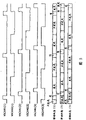
Figure 10 and 11 has illustrated the example of the driving time of the second sweep trace VSCAN2, and wherein a field duration comprises single light period.Particularly, Figure 10 has illustrated that the light period in the field duration is the example of the driving time under 50% the situation, and Figure 11 has illustrated that light period in the field duration is another example of the driving time under 20% the situation.In Figure 10 and Figure 11, illustrated that phase relation has constituted a circulation with 20 lines.
Should be noted in the discussion above that the light period corresponding to s bar sweep trace VSCAN2 (s) can be calculated by expression formula given below.Yet, suppose that a field duration is a m horizontal scanning period, in s horizontal scanning period, carry out write operation, and carry out luminous simultaneously to s horizontal scanning line VSCAN2 (s).Further, light period shared ratio in a field duration T is represented by DUTY.
Simultaneously, light period and dark period are calculated by following expression respectively:
Light period:
[(s-1)/m]·T<t<{[(s-1)/m]+DUTY}·T
Dark period:
{[(s-1)/m]+DUTY}·T<t<{[(s-1)/m]+1}·T
Here, t satisfies the cycle that is calculated by following expression:
[(s-1)/m]·T<t<{[(s-1)/m]+1}·T
Relevant technology is open in JP-A-2002-514320, Jap.P. open source literature 2005-027028 number and Jap.P. open source literature 2006-215213 number.
Embodiment
Below, the active matrix drive-type organic EL panel of using the embodiment of the invention is described.
Should be noted in the discussion above that technical field technique known under the embodiment of the invention provides and do not have disclosed content in this instructions and the accompanying drawing.
A. the structure of organic EL panel
Figure 17 represents to use the example of overall arrangement of the organic EL panel of the embodiment of the invention.
With reference to Figure 17, organic EL panel 21 comprises pixel array portion 3, be used for the first scanning line driving part 5 of write signal voltage, be used to control the second scanning line driving part 7, data line drive part 9 and the fluorescent lifetime determining section 23 of light period.Pixel array portion 3 comprise be arranged to M capable * image element circuit 11 of N row.The value of M and N depends on display result.
Fluorescent lifetime determining section 23 is organic EL panel 21 distinctive assemblies.The total light period that occupies among the one field duration T (ratio DUTY) is provided for fluorescent lifetime determining section 23.Fluorescent lifetime determining section 23 is determined the layout of light period, thereby satisfies the total light period (ratio DUTY) that is provided for it.Here, determine the layout of light period for each second sweep trace VSCAN2.
Although below described specific definite method of light period, wherein in a field duration, distribute a plurality of light periods, but fluorescent lifetime determining section 23 is controlled the light period length of specific light period and other light periods changeably, thereby specific light period becomes luminous center.The fluorescent lifetime determining section 23 and the second scanning line driving part 7 are corresponding to " display panel drive part ".
Should be noted that, in order to reduce flicker and motion artifact to improve image quality, wish to determine the time so that be equal to or greater than 25% of a field duration, but be equal to or less than 75% of a field duration from the Cycle Length of start time to the concluding time of last (last-time) light period of (first-time) light period for the first time.
Fluorescent lifetime determining section 23 operation is with the beginning pulsed D SST of start time from each light period to 7 supplies of the second scanning line driving part that be used to provide be used to provide the end pulsed D SET of the concluding time of each light period and clock DSCK.
B. drive example
B-1. the driving example 1 of display panel
Here, described under two light periods are dispensed on situation in the field duration, the length in driven for emitting lights cycle is so that the ratio between the first and second light period length is the driving example of 3:1 changeably.
The example of the driving time of Figure 18 and 19 explanations, the second sweep trace VSCAN2, wherein a field duration comprises two light periods.In two examples of Figure 18 and 19, the start time of light period is fixed to 0% of a field duration for the first time, and the start time of light period is fixed to 75% of a field duration for the second time.Should be noted in the discussion above that Figure 18 corresponding to the relatively short situation of total light period length, and Figure 19 is corresponding to another relatively long situation of total light period length.
Incidentally, constitute the circulation with 20 lines although show phase relation in Figure 18 and 19, this example to prior art described above is similar, and in fact phase relation is set so that become a circulation with M bar line.
Simultaneously, fluorescent lifetime determining section 23 is determined the light period corresponding to s bar sweep trace VSCAN2 (s) according to expression formula given below.
Yet, present following calculation expression so that by a m given field duration of horizontal scanning period.Further, present s bar sweep trace VSCAN2 (s), so that in s horizontal scanning period, carry out write operation and begin luminous simultaneously.Further, total light period shared ratio in a field duration T is represented by DUTY.Should be noted in the discussion above that if result calculated is not a round values, then is that unit regulates the corresponding time with the clock.
Simultaneously, light period and dark period are calculated by following expression:
Light period for the first time:
[(s-1)/m]·T<t<{[(s-1)/m]+DUTY·(3/4)}·T
Dark period for the first time:
{[(s-1)/m]+DUTY·(3/4)·T<t<{[(s-1)/m]+0.75}·T
Light period for the second time:
{[(s-1)/m]+0.75}·T<t<{[(s-1)/m]+0.75+DUTY·(1/4)}·T
Dark period for the second time:
{[(s-1)/m]+0.75+DUTY·(1/4)}·T<t<{[(s-1)/m]+1}·T
Here, t satisfies the cycle that is calculated by following expression:
[(s-1)/m]·T<t<{[(s-1)/m]+1}·T
In this drove example, the length of light period equaled three times of length of light period for the second time for the first time.Correspondingly, even in a field duration, there are two light periods,, visually mainly observe light period for the first time still owing to the difference of brightness between two light periods.Therefore, can reduce the phenomenon that image visually is observed to the slur picture significantly.
Should be noted in the discussion above that in this driving example, can in 0% to 100% scope, control total light period changeably.Correspondingly, this driving example makes the luminosity of organic EL panel maximize effectively.
Yet as mentioned above, in this drove example, the adjusting step-length of light period had the time span of three times of adjusting step-lengths that equal light period for the second time usually for the first time.This is because the control light period makes that the length ratio between first and second light periods is 3:1.
Correspondingly, in this drove example, the adjusting step-length number of adjustable luminance level was reduced to 1/4th of the situation that comprises single light period among Figure 20.On the other hand, the adjusting step-length width of luminance level increases to four times of the situation that comprises a light period.
Correspondingly, in order steadily to control luminance level, for example, need to reduce one and regulate step-length.In this example, if one regulate step-length be set to 1% 1/4th, that is, be set to 0.25, then can make the variation unit of luminance level conform to the situation that comprises a light period.
Yet, such possibility is still arranged, that is, depend on a size of regulating step-length, may regulate step-length less than one according to the above expression formula result calculated that provides.In such example,, can repeat to add and deletion adjusting step-length in the field formerly and subsequently, to tackle this example although do not satisfy the relation of 3:1 strictly.
Perhaps, as shown in Figure 21, can in the scope of the adjusting step-length that is assigned to each light period, regulate step-length ground control light period length one by one.In this example, the light period and the situation of the length of light period for the first time for the second time appear side by side not regulating.Correspondingly, the expression formula that provides more than can't using, and can't satisfy the relation of 3:1.
Yet, still in this example since for the first time light period and for the second time the luminance difference between the light period can be maintained at and be equal to and greater than 3:1, therefore can reduce the slur picture of image.
Other that should be noted in the discussion above that the control technology of this adjusting step-length can also be applied to describing below drive examples.
B-2. the driving example 2 of display panel
In above-mentioned driving example 1, a field duration can farthest be utilized so that control peak brightness level.Yet, because for the second time the start time of light period even total therefore light period length is lacked, also is difficult to avoid obvious light period length elongated in 75% position.Therefore, motion artifact may appear.
Therefore, in the driving example that is described below, be used to provide the maximal value of total light period length (ratio DUTY) of the regulated quantity of peak brightness level to be set to 60% of a field duration.Should be noted in the discussion above that still in this drivings example, for the first time the length of light period and the second time light period length between ratio be set to 3:1.
The example of the driving time of the second sweep trace VSCAN2 of Figure 22 and 23 explanations and this Driving technique compatibility.In two examples of Figure 22 and 23, the start time of light period is fixed to 0% of a field duration for the first time, and the start time of light period is fixed to 45% of a field duration for the second time.Should be noted in the discussion above that Figure 22 corresponding to the relatively short situation of total light period length, and Figure 23 is corresponding to another relatively long situation of total light period length.
Incidentally, constitute the circulation with 20 lines although show phase relation in Figure 22 and 23, this example to prior art described above is similar, and in fact phase relation is set so that constitute a circulation with M bar line.
Simultaneously, fluorescent lifetime determining section 23 is determined the light period corresponding to s bar sweep trace VSCAN2 (s) according to expression formula given below.
Yet, present following calculation expression so that provide a field duration by m horizontal scanning period.Further, present s bar sweep trace VSCAN2 (s) so that in s horizontal scanning period, carry out write operation and begin luminous simultaneously.
Further, total light period shared ratio in a field duration T is represented by DUTY.Should be noted in the discussion above that if result calculated is not a round values, then is that unit regulates the corresponding time with the clock.
Simultaneously, light period and dark period are calculated by following expression:
0<DUTY<0.6 wherein,
Light period for the first time:
[(s-1)/m]·T<t<{[(s-1)/m]+DUTY·(3/4)}·T
Dark period for the first time:
{[(s-1)/m]+DUTY·(3/4)}·T<t<{[(s-1)/m]+0.45}·T
Light period for the second time:
{[(s-1)/m]+0.75}·T<t<{[(s-1)/m]+0.45+DUTY·(1/4)}·T
Dark period for the second time:
{[(s-1)/m]+0.45+DUTY·(1/4)}·T<t<{[(s-1)/m]+1}·T
If adopt this driving example, then can in 0% to 60% the scope of a field duration T, regulate the total light period length (ratio DUTY) that has in the field duration T.
From the angle of motion artifact or flicker, drive example according to this, obvious light period can be controlled in 45% to 60%.
Therefore, from flicker and two angles of motion artifact, can suppress the deterioration of image quality.
By this way, when using driving example 2, can suppress the deterioration of image quality simultaneously in wide region adjusted peak brightness level.
B-3. the driving example 3 of display panel
In above-mentioned driving example 2, in the method, the start time of each light period is fixed, and the concluding time of each light period is delayed according to the increase of light period length always.
In this driving example 3 that is described below, control each light period length changeably, thereby the first time light period start time and for the second time length between concluding time of light period be under the situation of fixing, filled up the interval between two light periods.
Particularly, in response to total light period length (ratio DUTY), the concluding time of the control light period first time and the start time of light period changeably for the second time.
Figure 24 and 25 explanations are corresponding to the example of the driving time of the second sweep trace VSCAN2 of this Driving technique.
Should be noted in the discussion above that Figure 24 and 25 all is set to 60% the situation of a field duration corresponding to the maximal value of total light period length (ratio DUTY) of the regulated quantity that is used to provide the peak brightness level.Further, still drive in example at this, the ratio between the length of the length of light period and the light period second time is 3:1 for the first time.
Therefore, in the example of Figure 24 and 25, the start time of light period is fixed to 0% of a field duration for the first time, and the concluding time of light period is fixed to 60% of a field duration for the second time.Should be noted in the discussion above that Figure 24 corresponding to the relatively short situation of total light period length, and Figure 25 is corresponding to another relatively long situation of total light period length.
Incidentally, constitute the circulation with 20 lines although show phase relation in Figure 24 and 25, this example to prior art described above is similar, and in fact phase relation is set to and constitutes the circulation with M bar line.
Simultaneously, fluorescent lifetime determining section 23 is determined the light period corresponding to s bar sweep trace VSCAN2 (s) according to expression formula given below.
Yet, present following calculation expression so that provide a field duration by m horizontal scanning period.Further, present s bar sweep trace VSCAN2 (s) so that in s horizontal scanning period, carry out write operation and begin luminous simultaneously.
Further, total light period shared ratio in a field duration T is represented by DUTY.Should be noted in the discussion above that if result calculated is not a round values, then is that unit regulates the corresponding time with the clock.
Simultaneously, light period and dark period are calculated by following expression:
0<DUTY<0.6 wherein,
Light period for the first time:
[(s-1)/m]·T<t<{[(s-1)/m]+DUTY·(3/4)}·T
Dark period for the first time:
{[(s-1)/m]+DUTY·(3/4)}·T<t<{[(s-1)/m]+0.6-DUTY·(1/4)}·T
Light period for the second time:
{[(s-1)/m]+0.6-DUTY·(1/4)}·T<t<{[(s-1)/m]+0.6}·T
Dark period for the second time:
{[(s-1)/m]+0.6}·T<t<{[(s-1)/m]+1}·T
By as can be known aforementioned, still drive in example at this, can in 0% to 60% the scope of a field duration T, regulate the total light period length (ratio DUTY) that has in the field duration T.
From the angle of motion artifact or flicker, drive example according to this, obvious light period can be controlled to 60%.
Therefore, from flicker and two angles of motion artifact, can suppress the deterioration of image quality.
By this way, using under the situation that drives example 3, can suppress the deterioration of image quality simultaneously in wide region adjusted peak brightness level.
Yet, as mentioned above, still driving in the example at this, the adjusting step-length of light period has three times time span of the adjusting step-length that equals the light period second time usually for the first time.
Correspondingly, still drive in example at this, the adjusting step-length of adjustable luminance level is reduced to 1/4th of the situation that comprises single light period.On the other hand, the variation unit of luminance level increases to four times of the situation that comprises a light period.
Correspondingly, in order steadily to control luminance level, for example, step-length is regulated in one of essential minimizing.In this example, if one regulate step-length be set to 1% 1/4th, that is, be set at 0.25, then can make the variation unit of luminance level conform to the situation that comprises a light period.
Yet, such possibility is still arranged, that is, depend on a size of regulating step-length, can regulate step-length less than one according to the above expression formula result calculated that provides.In such example,, can repeat to add and deletion adjusting step-length in the field formerly and subsequently, to tackle this example although do not satisfy the relation of 3:1 strictly.
Perhaps, as shown in Figure 26, can in the scope of the adjusting step-length that is assigned to each light period, regulate step-length ground control light period length one by one.In this example, the light period and the situation of the length of light period for the first time for the second time appear side by side not regulating.Correspondingly, the expression formula that provides more than can't using, and can't satisfy the relation of 3:1.
Yet, still in this example since for the first time light period and for the second time the luminance difference between the light period can be maintained at and be equal to and greater than 3:1, therefore can reduce the possibility that image visually is observed to the slur picture usually.
Other that should be noted in the discussion above that the control technology of this adjusting step-length can also be applied to describing below drive examples.
B-4. the driving example 4 of display panel
Here, the driving example that is different from driving example described above is described.Drive in the example at this,, side by side control the start time and the concluding time of a light period in two light periods changeably in response to total light period length (ratio DUTY).
Therefore, drive in the example at this, a field duration is divided into three cycles fifty-fifty.Distribution method as three cycles, a kind of method is to be assigned to light period for the first time first and second cycles, period 3 is assigned to light period for the second time, another kind method is to be assigned to light period for the first time the period 1, and second and the period 3 be assigned to light period for the second time.
In both of these case, two cycles that are assigned to a light period are later half corresponding to the preceding half-sum of light period.
Should be noted in the discussion above that in this driving example, be set to wherein distribute the light period in two cycles as the reference point of point of fixity.With reference to this reference point, determine the start time and the concluding time of light period.
Particularly, the start time is set to time of 1/3rd of total light period length (ratio DUTY) before reference point, and the concluding time is set to time of 1/3rd of total light period length (ratio DUTY) after reference point.
In the following description, the maximal value of total light period length (ratio DUTY) is set to 60%, and 40% point, and promptly 2/3 place of maximum changing range is set to the reference point to the light period second time.In other words, for the first time the length of light period and for the second time the ratio between the length of light period be set to 1:2.In this example, for the first time the variation range of light period is by being 0% to 20% to provide, and the variation range of light period provides by 20% to 60% for the second time.
Figure 27 and 28 explanations are corresponding to the example of the driving time of the second sweep trace VSCAN2 of this Driving technique.
Should be noted in the discussion above that Figure 27 corresponding to the relatively short situation of total light period length, and Figure 28 is corresponding to the relatively long situation of total light period length.
Incidentally, constitute the circulation with 20 lines although also show phase relation in Figure 27 and 28, this example to prior art described above is similar, and in fact phase relation is set to and constitutes the circulation with M bar line.
Simultaneously, fluorescent lifetime determining section 23 is determined the light period corresponding to s bar sweep trace VSCAN2 (s) according to expression formula given below.
Yet following calculation expression also shows by m horizontal scanning period and provides a field duration.Further, s bar sweep trace VSCAN2 (s) shows and carries out write operation and begin luminous simultaneously in s horizontal scanning period.
Further, total light period shared ratio in a field duration T is represented by DUTY.Should be noted in the discussion above that if result calculated is not a round values, then is that unit regulates the corresponding time with the clock.
Simultaneously, light period and dark period are calculated by following expression:
0<DUTY<0.6 wherein,
Light period for the first time:
[(s-1)/m]·T<t<{[(s-1)/m]+DUTY·(1/3)}·T
Dark period for the first time:
{[(s-1)/m]+DUTY·(1/3)}·T<t<{[(s-1)/m]+0.4-DUTY·(1/3)}·T
Light period for the second time:
{[(s-1)/m]+0.4-DUTY·(1/3)}·T<t<{[(s-1)/m]+0.4+DUTY·(1/3)}·T
Dark period for the second time:
{[(s-1)/m]+0.4+DUTY·(1/3)}·T<t<{[(s-1)/m]+1}·T
By as can be known aforementioned, also in this drives example, can in 0% to 60% the scope of a field duration T, regulate the total light period length (ratio DUTY) that has in the field duration T.
From the angle of motion artifact or flicker, drive example according to this, obvious light period can be controlled in 40% to 60%.
Therefore, from flicker and two angles of motion artifact, can suppress the deterioration of image quality.
By this way, using under the situation that drives example 3, can suppress the deterioration of image quality simultaneously in wide region adjusted peak brightness level.
B-5. the driving example 5 of display panel
Here, be described in the driving example of arranging three light periods in the field duration.
And in this example, control method as light period, available a kind of method is that light period length has the wherein big relation of monotone increasing (length of the length<light period 3 of the length<light period 2 of light period 1), and another kind of method is that light period length has dullness and reduces relation (length of light period 1〉length of light period 2〉length of light period 3).
Yet the light period length of describing second light period here, is set to the longest another kind of method.This is because second light period is positioned at the center of light period, and, seeming situation about increasing at moving image, an image that wherein is positioned at the center seems the most clear.
Here, the concluding time of having described variable control light period makes the light period length of light period can satisfy the relation of 1:2:1.
Should be noted in the discussion above that the regulated quantity of peak brightness level is 100% of a field duration in the maximal value of total light period (ratio DUTY).
Particularly, describe wherein and 25% be assigned to light period for the first time, 50% is assigned to light period for the second time, and 25% is assigned to the example of the 3rd light period.
Correspondingly, drive in the example at this, the start time of light period is fixed to 0% for the first time, and the start time of light period is fixed to 25% for the second time, and the start time of light period is fixed to 75% for the third time.
Figure 29 and 30 explanations are corresponding to the example of the driving time of the second sweep trace VSCAN2 of this Driving technique.
Should be noted in the discussion above that Figure 29 corresponding to the relatively short situation of total light period length, and Figure 30 is corresponding to the relatively long situation of total light period length.
Incidentally, constitute the circulation with 20 lines although show phase relation in Figure 29 and 30, this example to prior art described above is similar, and in fact phase relation is set to and constitutes the circulation with M bar line.
Simultaneously, fluorescent lifetime determining section 23 is determined the light period corresponding to s bar sweep trace VSCAN2 (s) according to expression formula given below.
Yet, provide a field duration by m horizontal scanning period to such an extent as to also present following calculation expression.Further, s bar sweep trace VSCAN2 (s) shows and carries out write operation and begin luminous simultaneously in s horizontal scanning period.
Further, total light period shared ratio in a field duration T is represented by DUTY.Should be noted in the discussion above that if result calculated is not a round values, then is that unit regulates the corresponding time with the clock.
Simultaneously, light period and dark period are calculated by following expression:
0<DUTY<1 wherein,
Light period for the first time:
[(s-1)/m]·T<t<{[(s-1)/m]+DUTY·(1/4)}·T
Dark period for the first time:
{[(s-1)/m]+DUTY·(1/4)}·T<t<{[(s-1)/m]+0.25}·T
Light period for the second time:
{[(s-1)/m]+0.25}·T<t<{[(s-1)/m]+0.25+DUTY·(2/4)}·T
Dark period for the second time:
{[(s-1)/m]+0.25+DUTY·(2/4)}·T<t<{[(s-1)/m]+0.75}·T
Light period for the third time:
{[(s-1)/m]+0.75}·T<t<{[(s-1)/m]+0.75+DUTY·(1/4)}·T
Dark period for the third time:
{[(s-1)/m]+0.75+DUTY·(1/4)}·T<t<{[(s-1)/m]+1}·T
In this drives example, can in 0% to 100% the scope of a field duration T, regulate the total light period length (ratio DUTY) that has in the field duration T.
Further, drive in the example, control the distributive law of the fluorescent lifetime length of light period changeably, thereby second light period can be at luminous center at this.
Correspondingly, can suppress image effectively and visually be observed to triple phenomenons.
B-6. the driving example 6 of display panel
According to above-mentioned driving example 5, a field duration can farthest be utilized so that control peak brightness level.Yet, because the variation range of light period extends on whole field duration, therefore, existence may with the related possibility of motion artifact.
Therefore, drive in the example at this, the maximal value (ratio DUTY) of total light period length is provided, to the maximal value (ratio DUTY) of total light period length, the regulated quantity of peak brightness level is 60% of a field duration.Should be noted in the discussion above that in this driving example, for the first time light period, for the second time light period and for the third time the ratio of the length of light period be set to 1:2:1.
Particularly, drive in the example at this, 15% is assigned to light period for the first time, and 30% is assigned to light period for the second time, and 15% is assigned to the 3rd light period.
Correspondingly, drive in the example at this, the start time of light period is fixed to 0% for the first time, and the start time of light period is fixed to 15% for the second time, and the start time of light period is fixed to 45% for the third time.
Figure 31 and 32 explanations are corresponding to the example of the driving time of the second sweep trace VSCAN2 of this Driving technique.The start time that Figure 31 and 32 all shows the light period first time is fixed to 0%, and the start time of light period is fixed to 15% for the second time, and the start time of light period is fixed to 45% for the third time.Should be noted in the discussion above that Figure 31 corresponding to the relatively short situation of total light period length, and Figure 32 is corresponding to the relatively long situation of total light period length.
Incidentally, constitute the circulation with 20 lines although show phase relation in Figure 31 and 32, this example to prior art described above is similar, and in fact phase relation is set to and constitutes the circulation with M bar line.
Simultaneously, fluorescent lifetime determining section 23 is determined the light period corresponding to s bar sweep trace VSCAN2 (s) according to expression formula given below.
Yet following calculation expression also shows by m horizontal scanning period and provides a field duration.Further, s bar sweep trace VSCAN2 (s) shows and carries out write operation and begin luminous simultaneously in s horizontal scanning period.
Further, total light period shared ratio in a field duration T is represented by DUTY.Should be noted in the discussion above that if result calculated is not a round values, then is that unit regulates the corresponding time with the clock.
Simultaneously, light period and dark period are calculated by following expression:
0<DUTY<0.6 wherein,
Light period for the first time:
[(s-1)/m]·T<t<{[(s-1)/m]+DUTY·(1/4)}·T
Dark period for the first time:
{[(s-1)/m]+DUTY·(1/4)}·T<t<{[(s-1)/m]+0.15}·T
Light period for the second time:
{[(s-1)/m]+0.15}·T<t<{[(s-1)/m]+0.15+DUTY·(2/4)}·T
Dark period for the second time:
{[(s-1)/m]+0.15+DUTY·(2/4)}·T<t<{[(s-1)/m]+0.45}·T
Light period for the third time:
{[(s-1)/m]+0.45}·T<t<{[(s-1)/m]+0.45+DUTY·(1/4)}·T
Dark period for the third time:
{[(s-1)/m]+0.45+DUTY·(1/4)}·T<t<{[(s-1)/m]+1}·T
Adopting under this situation that drives example, can in 0% to 60% the scope of a field duration T, regulate the total light period length (ratio DUTY) that has in the field duration T.
From the angle of motion artifact or flicker, drive example according to this, obvious light period can be controlled in 45% to 60%.
Therefore, from flicker and two angles of motion artifact, can suppress the deterioration of image quality.
So, using under the situation that drives example 6, can suppress the deterioration of image quality simultaneously in wide region adjusted peak brightness level.
B-7. the driving example 7 of display panel
Here, in driving example 7, the change technique that drives example 3 is applied to the light period length of the first and the 3rd light period in three light periods, the change technique that drives example 4 is applied to the light period length of second light period.
Particularly, the concluding time of the start time of first light period and the 3rd light period is fixed, and other times are controlled changeably, with reference to this reference point, control the start and end time of second light period changeably.
Should be noted in the discussion above that still that in this driving example it is 60% of a field duration that the maximal value of total light period length (ratio DUTY) of the regulated quantity of peak brightness level is provided.Further, for the first time light period, for the second time light period and for the third time the ratio of the length of light period be set to 1:2:1.
Particularly, drive in the example at this, 15% is assigned to light period for the first time, and 30% is assigned to light period for the second time, and 15% is assigned to the 3rd light period.
Correspondingly, drive in the example at this, the start time of light period is fixed to 0% for the first time, and the start time of light period is fixed to 30% for the second time, and the start time of light period is fixed to 60% for the third time.
Figure 33 and 34 explanations are corresponding to the example of the driving time of the second sweep trace VSCAN2 of this Driving technique.Should be noted in the discussion above that Figure 33 corresponding to the relatively short situation of total light period length, and Figure 34 is corresponding to the relatively long situation of total light period length.
Incidentally, constitute the circulation with 20 lines although show phase relation in Figure 33 and 34, this example to prior art described above is similar, and in fact phase relation is set to and constitutes the circulation with M bar line.
Simultaneously, fluorescent lifetime determining section 23 is determined the light period corresponding to s bar sweep trace VSCAN2 (s) according to expression formula given below.
Yet following calculation expression also shows by m horizontal scanning period and provides a field duration.Further, s bar sweep trace VSCAN2 (s) shows and carries out write operation and begin luminous simultaneously in s horizontal scanning period.
Further, total light period shared ratio in a field duration T is represented by DUTY.Should be noted in the discussion above that if result calculated is not a round values, then is that unit regulates the corresponding time with the clock.
Simultaneously, light period and dark period are calculated by following expression:
0<DUTY<0.6 wherein,
Light period for the first time:
[(s-1)/m]·T<t<{[(s-1)/m]+DUTY·(1/4)}·T
Dark period for the first time:
{[(s-1)/m]+DUTY·(1/4)}·T<t<{[(s-1)/m]+0.3-DUTY·(1/4)}·T
Light period for the second time:
{[(s-1)/m]+0.3-DUTY·(1/4)}·T<t<{[(s-1)/m]+0.3+DUTY·(1/4)}·T
Dark period for the second time:
{[(s-1)/m]+0.3+DUTY·(1/4)}·T<t<{[(s-1)/m]+0.6-DUTY·(1/4)}·T
Light period for the third time:
{[(s-1)/m]+0.6-DUTY·(1/4)}·T<t<{[(s-1)/m]+0.6}·T
Dark period for the third time:
{[(s-1)/m]+0.6}·T<t<{[(s-1)/m]+1}·T
Adopting under this situation that drives example, can in 0% to 60% the scope of a field duration T, regulate the total light period length (ratio DUTY) that has in the field duration T.
From the angle of motion artifact or flicker, drive example according to this, obvious light period can be controlled to 60%.
Therefore, from flicker and two angles of motion artifact, can suppress the deterioration of image quality.
So, using under the situation that drives example 7, can suppress the deterioration of image quality simultaneously in wide region adjusted peak brightness level.
C. other embodiment
C-1. the relative ratios between the light period length
In driving example described above, has the light period of long hair photoperiod length and the ratio that has between the light period of bob photoperiod length is 3:1 or 2:1.
Yet the ratio between the light period may be different from specific ratios.To should be noted in the discussion above that in order allowing and visually mainly observe a light period in a plurality of light periods, the ratio between the light period length preferably is equal to or greater than 1.5:1.
C-2. regulate the control of step-length
In driving example described above, a field duration comprises two light periods, and regulating step-length with one is the length that unit changes one of light period.
Naturally, also the number of the light period in a field duration be three or more situation under, similarly, have only that can to regulate step-length with one be the length that unit controls one of light period changeably.
Should be noted that, although regulating the step-length width becomes greater than an adjusting step-length, if but the number of the light period of its length of regulating step ground change is N-1 one by one, so, owing to regulate the length of all N of change light period of step-length one by one, can reduce to regulate the step-length width.Therefore, can increase the adjusting step-length number of peak brightness and reduce to regulate the step-length width, thereby change brightness reposefully.
C-3. product example
A. drive IC
In the description in front, pixel array portion and driving circuit are formed on the panel.
Yet, can be separated from each other and make and distribution pixel array portion 3 and scanning line driving part 5,7,9,23 etc.For example, can construct as the scanning line driving part 5,7,9,23 of drive IC (integrated circuit) independently etc., and form the equally independently plate of pixel array portion 3 above being distributed in.
B. display module
Organic EL panel 21 in the foregoing description can distribute with the form of display module 31 with appearance shown in Figure 35 configuration.
Display module 31 has the structure that reverse side part 33 adheres to the surface of back up pad 35.Reverse side part 33 comprises the substrate that the transparent component by glass etc. forms, and has and be disposed in its lip-deep color filter, diaphragm, photomask etc.
Should be noted in the discussion above that to be used for the flexible print circuit (FPC) 37 that input and output come the signal of self-supporting slab 35 outsides, vice versa, and other necessary elements may be provided on the display module 31.
C. electronic equipment
Organic EL panel among the embodiment described above also is incorporated in the form operation of the commodity in the electronic equipment with organic EL panel.
Figure 36 represents the example of the configuration of electronic equipment 41.With reference to Figure 36, electronic equipment 41 comprises it can being the organic EL panel 43 and the system control block 45 of any organic EL panel described above.The essence of the processing of being carried out by system control block 45 depends on the form of the commodity of electronic equipment 41.
Should be noted in the discussion above that electronic equipment 41 is not limited to the equipment of specific area, as long as it incorporates the function that is presented at the image that produces in the electronic equipment 41 or import from the outside into.
The electronic equipment 41 of the type of describing can be, for example, and televisor.The example of the profile of televisor shown in Figure 37 51.
The display screen 57 that is formed by header board 53, filter glass plate 55 etc. is disposed in the front of the housing of televisor 51.Display screen 57 is corresponding to the described above organic EL panel relevant with present embodiment.
Perhaps, electronic equipment 41 can be, for example, and digital camera.The example of the profile of digital camera 61 shown in Figure 38 A and the 38B.Figure 38 A illustrates the example of profile that the front is the digital camera 61 of image pickup object side, and Figure 38 B illustrates the example of profile that the back is the digital camera 61 of image pickup user side.
Digital camera 61 comprises the unshowned image pickup camera lens that is disposed in over cap 63 back, and over cap 63 is in closed condition among Figure 38 A.Digital camera 61 further comprises flash of light piece 65, display screen 67, gauge tap 69 and shutter release button 71.Display screen 67 is corresponding to the described above organic EL panel relevant with present embodiment.
Perhaps, electronic equipment 41 can be, for example, and video camera.Figure 39 illustrates the example of the profile of video camera 81.
With reference to Figure 39, shown video camera 81 comprises that being used for image pickup camera lens 85, image pickup that captured image picks up anterior office image, that be provided at main body 83 of object begins/shutdown switch 87 and display screen 89.Display screen 89 is corresponding to the described above organic EL panel relevant with present embodiment.
Perhaps, electronic equipment 41 for example can be, portable terminal.Figure 40 A and 40B illustrate the example as the profile of the pocket telephone 91 of portable terminal.With reference to figure 40A and 40B, shown pocket telephone 91 is folded forms, and Figure 40 A illustrates the pocket telephone 91 that is in the state of opening, and Figure 40 B illustrates the pocket telephone 91 that is in folded state.
Pocket telephone 91 comprises coupling part 97, display screen 99, auxiliary display screen 101, picture lamp 103 and the image pickup camera lens 105 of side body 93, following side body 95, hinge form.Display screen 99 and auxiliary display screen 101 are corresponding to the described above organic EL panel relevant with present embodiment.
In addition, electronic equipment 41 can be, for example, and computing machine.Figure 41 illustrates the example of the profile of notebook 111.
Notebook 111 comprises following side body 113, goes up side body 115, keyboard 117 and display screen 119.Display screen 119 is corresponding to the described above organic EL panel relevant with present embodiment.
Electronic equipment 41 can also be formed reproducer, game machine, e-book, electronic dictionary etc.
C-4. other examples of display device
Driving method described above can also be applied to other equipment except that organic EL panel.For example, these driving methods for example can be applied to inorganic EL panel, the light-emitting component arranging the display panel of LED and wherein have other diode structures thereon is arranged on lip-deep emissive type display panel.
Further, driving method described above can also be applied to non-emissive type display panel, such as display panels.
C-5. other examples of image element circuit
In the description in front, the image element circuit of active matrix drive-type has been described with reference to figure 2 and 3.
Yet the configuration of image element circuit is not limited to this, and the present invention can also be applied to the image element circuit of existing image element circuit and the various configurations that may propose in the future.
In spirit and scope of the invention, can change embodiment described above in every way.Further, based on content disclosed by the invention, can implement various modification and application by certain operations or combination.
It is the theme of the Japanese patent application of 2007-148699 that the application comprises the application number that relates on June 5th, 2007 and file an application to the Japan special permission Room, incorporates its full content into as a reference at this.