CN101276125B - Laser generating apparatus - Google Patents
Laser generating apparatus Download PDFInfo
- Publication number
- CN101276125B CN101276125B CN2008100898086A CN200810089808A CN101276125B CN 101276125 B CN101276125 B CN 101276125B CN 2008100898086 A CN2008100898086 A CN 2008100898086A CN 200810089808 A CN200810089808 A CN 200810089808A CN 101276125 B CN101276125 B CN 101276125B
- Authority
- CN
- China
- Prior art keywords
- external resonator
- signal
- phase
- laser
- resonator
- Prior art date
- Legal status (The legal status is an assumption and is not a legal conclusion. Google has not performed a legal analysis and makes no representation as to the accuracy of the status listed.)
- Expired - Fee Related
Links
Images


Classifications
-
- G—PHYSICS
- G02—OPTICS
- G02F—OPTICAL DEVICES OR ARRANGEMENTS FOR THE CONTROL OF LIGHT BY MODIFICATION OF THE OPTICAL PROPERTIES OF THE MEDIA OF THE ELEMENTS INVOLVED THEREIN; NON-LINEAR OPTICS; FREQUENCY-CHANGING OF LIGHT; OPTICAL LOGIC ELEMENTS; OPTICAL ANALOGUE/DIGITAL CONVERTERS
- G02F1/00—Devices or arrangements for the control of the intensity, colour, phase, polarisation or direction of light arriving from an independent light source, e.g. switching, gating or modulating; Non-linear optics
- G02F1/35—Non-linear optics
- G02F1/353—Frequency conversion, i.e. wherein a light beam is generated with frequency components different from those of the incident light beams
-
- H—ELECTRICITY
- H01—ELECTRIC ELEMENTS
- H01S—DEVICES USING THE PROCESS OF LIGHT AMPLIFICATION BY STIMULATED EMISSION OF RADIATION [LASER] TO AMPLIFY OR GENERATE LIGHT; DEVICES USING STIMULATED EMISSION OF ELECTROMAGNETIC RADIATION IN WAVE RANGES OTHER THAN OPTICAL
- H01S3/00—Lasers, i.e. devices using stimulated emission of electromagnetic radiation in the infrared, visible or ultraviolet wave range
- H01S3/10—Controlling the intensity, frequency, phase, polarisation or direction of the emitted radiation, e.g. switching, gating, modulating or demodulating
-
- G—PHYSICS
- G02—OPTICS
- G02F—OPTICAL DEVICES OR ARRANGEMENTS FOR THE CONTROL OF LIGHT BY MODIFICATION OF THE OPTICAL PROPERTIES OF THE MEDIA OF THE ELEMENTS INVOLVED THEREIN; NON-LINEAR OPTICS; FREQUENCY-CHANGING OF LIGHT; OPTICAL LOGIC ELEMENTS; OPTICAL ANALOGUE/DIGITAL CONVERTERS
- G02F1/00—Devices or arrangements for the control of the intensity, colour, phase, polarisation or direction of light arriving from an independent light source, e.g. switching, gating or modulating; Non-linear optics
- G02F1/01—Devices or arrangements for the control of the intensity, colour, phase, polarisation or direction of light arriving from an independent light source, e.g. switching, gating or modulating; Non-linear optics for the control of the intensity, phase, polarisation or colour
- G02F1/0121—Operation of devices; Circuit arrangements, not otherwise provided for in this subclass
-
- G—PHYSICS
- G02—OPTICS
- G02F—OPTICAL DEVICES OR ARRANGEMENTS FOR THE CONTROL OF LIGHT BY MODIFICATION OF THE OPTICAL PROPERTIES OF THE MEDIA OF THE ELEMENTS INVOLVED THEREIN; NON-LINEAR OPTICS; FREQUENCY-CHANGING OF LIGHT; OPTICAL LOGIC ELEMENTS; OPTICAL ANALOGUE/DIGITAL CONVERTERS
- G02F1/00—Devices or arrangements for the control of the intensity, colour, phase, polarisation or direction of light arriving from an independent light source, e.g. switching, gating or modulating; Non-linear optics
- G02F1/35—Non-linear optics
- G02F1/3501—Constructional details or arrangements of non-linear optical devices, e.g. shape of non-linear crystals
- G02F1/3507—Arrangements comprising two or more nonlinear optical devices
-
- G—PHYSICS
- G02—OPTICS
- G02F—OPTICAL DEVICES OR ARRANGEMENTS FOR THE CONTROL OF LIGHT BY MODIFICATION OF THE OPTICAL PROPERTIES OF THE MEDIA OF THE ELEMENTS INVOLVED THEREIN; NON-LINEAR OPTICS; FREQUENCY-CHANGING OF LIGHT; OPTICAL LOGIC ELEMENTS; OPTICAL ANALOGUE/DIGITAL CONVERTERS
- G02F2203/00—Function characteristic
- G02F2203/15—Function characteristic involving resonance effects, e.g. resonantly enhanced interaction
Abstract
A laser light generating apparatus includes a laser light source, a phase-modulator, a signal generating unit configured to generate a modulation signal applied to the phase-modulator, a first external resonator, a second external resonator disposed at the stage succeeding the first external resonator, nonlinear optical elements each provided in the external resonators configured to implement wavelength conversion, an optical path length varying unit for varying the optical path length of each of the external resonators, and a control circuit having a negative feedback arrangement configured to obtain error signals for each of the external resonators, and configured to control the optical path length varying unit using the error signals according to FM sideband method. In the laser light generating apparatus, the external resonators are each held simultaneously in a resonance state by setting the frequency of the modulation signal and by controlling the optical path length of each of the external resonators.
Description
Technical field
Relate generally to generating device of laser of the present invention.More specifically, the present invention relates to comprise the generating device of laser of lasing light emitter and a plurality of external resonators, be used to utilize single modulation signal to come the steady lock of implement device.
Background technology
FM side band techniques (" Pound-Drever-Hall locking " technology) is usually as the example of the technology of the external resonator that is used for the steady lock generating device of laser, and is widely used in locking external resonator.
In FM sideband method, use the phase-modulator in order to the generated error signal of the prime that places external resonator to generate sideband wave.Generating under the situation of sideband wave, especially, need the high-performance phase-modulator that transmittance is higher and operating voltage is lower by the modulation ultraviolet light.
According to prior art, for fear of the excessive damage that causes by ultraviolet light to phase-modulator, the locking of ultraviolet light is to realize by constructing such generating device of laser, and described generating device of laser comprises a plurality of external resonators, locks a plurality of external resonators simultaneously and by the multistage wavelength Conversion that realizes according to the FM side band techniques.For example when using two external resonators, realize above-mentioned steps like this: at first first phase-modulator is arranged in the prime of first external resonator, first external resonator will be locked according to the FM side band techniques; Permission is incided on second phase-modulator through the light of the wavelength Conversion (that is the light after the generation wavelength Conversion) of first external resonator; Permission is incided on second external resonator from the light of second phase-modulator; And realizing the locking of second external resonator subsequently, is thereafter the conversion of another time wavelength.
But, lock simultaneously in the configuration of a plurality of resonators at above-mentioned needs, to have utilized and the as many phase-modulator of external resonator, reason is to have arranged a phase-modulator in the prime of each external resonator.In addition, owing to the optical crystal (nonlinear optical element) that in phase-modulator, comprises as primary clustering, so the manufacturing of phase-modulator is relatively more expensive comparatively speaking.Therefore, the increase of the number of resonator has caused the excessive increase of overall dimensions and installation cost.
In addition, be under the situation of ultraviolet light at the light of after wavelength Conversion, exporting, more a spot of relatively phase-modulator can be operated ultraviolet light, therefore has lower transmittance and relatively poor quality factor (figure of merit).This has caused several difficult points, for example, is used to provide the providing of high-voltage power supply of high working voltage, and the relatively short life-span that causes owing to the caused damage of ultraviolet light.
Japanese unexamined patent announces that No.2002-311467 discloses a kind of equipment and method, wherein, realizes multistage locking by import a plurality of modulation signals (carrier wave) to phase-modulator.
Though equipment of putting down in writing in above-mentioned Shen Qing Publication and method can compensate in the aforementioned difficult point some, what time wait to solve but in described equipment and method, still have, for example, use a plurality of signal generating units that a plurality of modulation signals are provided, and the complexity of the increase of signal Processing.
For using single modulation signal to lock the method for multistage external resonator, need make locking (resonant condition) stable by following manner: by increasing as much as possible from the modulated light (modulated light) of the external resonator reflection of the first order thus ratio increase the S/N ratio of error signal, thereby simultaneously by allowing modulated light to increase by the S/N ratio that is positioned at the detected error signal of other external resonator at different levels subsequently by the external resonator of the first order as much as possible.
Therefore, when the initial stage that be not provided with after upgrading external resonator integral body is optimized, perhaps the transmission width that external resonator takes place owing to the variation of resonator losses and conversion efficiency is over time the time, for the system that comprises a plurality of external resonators, faced the instable several difficult points that is absorbed in locking.
In addition, for the light after increasing wavelength conversion efficiency or obtaining powerful wavelength Conversion, powerful laser must shine external resonator, to realize the Wavelength of Laser conversion.Though this irradiation realizes by high power laser is incided on the phase-modulator, because the damage effect that laser radiation may cause, the intensity of incident laser only can be increased to the damage that phase-modulator is produced certain limit.This damage can be avoided by the phase-modulator that use is provided with the assembly of big effective diameter.But this makes the size of the optical crystal (nonlinear optical element) in the phase-modulator increase and thereby has increased its cost.Therefore, urgent hope can utilize low intensive laser to realize the stabilization signal modulation.
Summary of the invention
Consider above-mentioned difficult point, the objective of the invention is to use single modulation signal to solve the steady lock of each external resonator, this is to realize by externally generating the laser of wishing in the resonator according to FM sideband method.
To achieve these goals, according to a kind of form of the present invention, a kind of generating device of laser is provided, and it comprises that lasing light emitter, first and second external resonators and other a plurality of resonators, phase-modulator, signal generating unit, first and second nonlinear optical elements, optical path length change unit, at least one photodetector and control circuit.
Second external resonator is arranged in the back level of first external resonator; Phase-modulator is configured to be applied in modulation signal; Signal generating unit is arranged to and generates the modulation signal that imposes on phase-modulator; And being arranged in first and second nonlinear optical elements among first and second external resonators is arranged to the laser that is incident on each of first and second external resonators is implemented wavelength Conversion.In addition, optical path length changes the unit and is arranged to each the optical path length that changes in first and second external resonators, and at least one photodetector is arranged to reception from each the laser in first and second external resonators.In addition, control circuit with negative feedback configuration is arranged to and obtains at least one detection signal and the described modulation signal that is received by described at least one photodetector, thereby obtain to be used for each error signal of first and second external resonators, and be arranged to and control optical path length according to FM sideband method, use error signal and change the unit.
Become to equate by frequency configuration with following value with modulation signal, the feasible S/N ratio that is used for the error signal of each external resonator of this value can average out, and by utilizing control circuit to control the optical path length of each external resonator, each external resonator is remained on resonant condition simultaneously.As an example of the measure that is used for average S/N ratio, the frequency that imposes on the modulation signal of phase-modulator is configured such that long-pending P that the S/N that will be used for the error signal of each external resonator compares maintains and is approximately equal to its maximal value.
According to said structure, owing to formed such generating device of laser, this generating device of laser is configured to obtain the error signal of external resonators at different levels, and the frequency configuration that will impose on the modulation signal of phase-modulator becomes following value, this value makes the S/N ratio of error signal at different levels to average out, so the steady lock of all external resonators will be feasible.Especially, to be configured such that the S/N of error signal compares long-pending can be approximately equal to its maximal value the time when the frequency of modulation signal, can stablize a plurality of external resonators generally.
In addition, generating device of laser is provided preferably with modulating frequency the unit is set, be used to obtain the error signal that the variation by the transmission width of external resonator causes, and the frequency configuration that is used for imposing on the modulation signal of phase-modulator becomes following value, and this value makes the S/N of the error signal be used for each external resonator than averaging out separately.
According to having modulating frequency the said structure of unit is set, can be for example in time or the variation that causes by other factors and the frequency of modulation signal is set in response to the transmission width of external resonator, thereby can equalization be used for the S/N ratio of the error signal of each external resonator.As a result, even make that under the situation that locking condition changes, steady lock also will be feasible passing in time.
According to a kind of form of the present invention, it is configured to the feasible error signal that can detect external resonators at different levels, to be used for to generate required laser at a plurality of external resonators according to FM sideband method, and the frequency configuration of modulation signal can be become following value, this value makes the S/N ratio of each error signal of each external resonator of user average out.Therefore, it will be feasible using single modulation signal to come each external resonator is carried out steady lock.
Description of drawings
Fig. 1 is the diagrammatic sketch that schematically illustrates according to the basic configuration of generating device of laser of the present invention;
Fig. 2 is the diagrammatic sketch that schematically illustrates according to the generating device of laser of first embodiment of the invention;
Fig. 3 is the diagrammatic sketch that schematically illustrates the phase-modulator that can work under the bipolar driving pattern;
Fig. 4 is the diagrammatic sketch of exemplary circuit that illustrates the phase-modulator that is subjected to bipolar driving of Fig. 3;
Fig. 5 is the diagrammatic sketch that illustrates the basic configuration of the control system that comprises phase-modulator and photodetector;
Fig. 6 is the curve map that illustrates the usable reflection characteristic of external resonator;
Fig. 7 A and 7B are the diagrammatic sketch that illustrates the usable reflection characteristic and the relation between the modulating frequency of external resonator;
Fig. 8 is the dependent amplification diagrammatic sketch of δ that illustrates from the error signal of light detecting signal and modulation signal acquisition;
Fig. 9 A, 9B and 9C illustrate three grades of resonators separately at the effective reflectivity in when locking and the curve map of the correlativity between the error signal;
Figure 10 is the diagrammatic sketch that illustrates the variant of embodiment shown in Figure 1;
Figure 11 is the diagrammatic sketch that illustrates the basic configuration of another control system that comprises phase-modulator and photodetector;
Figure 12 is the diagrammatic sketch that schematically illustrates according to the generating device of laser of second embodiment of the invention;
Figure 13 is the diagrammatic sketch that schematically illustrates according to the generating device of laser of third embodiment of the invention;
Figure 14 is the diagrammatic sketch that schematically illustrates according to the generating device of laser of fourth embodiment of the invention; And
Figure 15 is the diagrammatic sketch that schematically illustrates according to the generating device of laser of fifth embodiment of the invention.
Embodiment
The present invention relates to comprise the lasing light emitter with continuous wave (CW) emissive ability and the generating device of laser of a plurality of external resonators, for example, it is suitable for by the multistage wavelength Conversion that realizes.With reference now to accompanying drawing,, shows several embodiments of the present invention by example.
<the first embodiment 〉
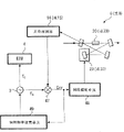
Below with reference to Fig. 1 to 9 generating device of laser according to first embodiment of the invention is described.Fig. 1 is the diagrammatic sketch that conceptually illustrates the basic configuration of present embodiment.
With reference to figure 1, generating device of laser 1 comprises lasing light emitter 2 at least, is used to export the laser that is essentially single-frequency.Pass through phase-modulator 4, optical system 5 from the laser of lasing light emitter 2 outputs, subsequently by a plurality of external resonators 6 to 12.In addition, phase-modulator 4 is provided with signal generating unit 3 (having the local oscillator that is used to generate oscillator signal), is used to generate the modulation signal that imposes on phase-modulator 4.Optical system 5 can comprise lens, prism, mirror alternatively and be used for other similar components of pattern match, and other assembly, for example dichroic mirror (dichroic mirror), suction strainer and be used for selective light and send it to other assembly of the resonator of next stage.
A plurality of external resonators 6 to 12 are arranged in the delegation end to end, comprise second external resonator of first external resonator and the back level that is arranged to first external resonator.In the following description to described device, external resonator 6 is regarded as first external resonator, and external resonator 9 is regarded as second external resonator.
Should be noted that first external resonator can be not limited to be positioned at the external resonator 6 of the first order, and any external resonator can serve as first external resonator.Similarly, second external resonator can be not limited to be positioned at partial external resonator 9, and any external resonator can serve as second external resonator, as long as this external resonator is positioned at the back level of first external resonator.In addition, this configuration for described device, need on the light path between the lasing light emitter 2 and first external resonator, a phase-modulator be set (promptly, phase-modulator 4 in this example), and need incide on second external resonator from the light of first external resonator output, and do not influence the phase modulation (PM) of phase-modulator 4.
Externally the inside of resonator 6 to 12 has been arranged SEVERAL NONLINEAR optical element (perhaps nonlinear optical crystal) 7 to 13 respectively.As nonlinear optical element, enumerated and to have realized relating to that the secondary harmonic light generates and the nonlinear optical element of (sum frequency) wavelength Conversion of generating etc. frequently.Alternately, can provide laser medium, to replace nonlinear optical element in the inside of each external resonator with gain amplifying power.
At least the first external resonator 6 in the external resonator and second external resonator 9 are provided with optical path length and change unit 18, are used for changing each optical path length of first and second external resonators.Optical path length changes unit 18 and is arranged to and carries out several controls, for example: use actuator such as VCM (voice coil motor), piezoelectric element etc. to come the servocontrol that the position and the posture of element included in the external resonator (mirror and other optical element) are carried out; And wait the control that optical characteristics (for example, refractive index and other similar parameters) is carried out by optical crystal being applied voltage.
The several optical systems 5 to 11 that are used for pattern match are disposed between the lasing light emitter 2 and first external resonator, and between the adjacent external resonator, with the necessary light that between lasing light emitter 2 and these resonators, is coupled efficiently.
In this configuration, enter the phase-modulator 4 that has been applied in the modulation signal that generates by signal generating unit 3 from lasing light emitter 2 emitted laser, thereby carried out phase modulation (PM) by preset frequency.After phase modulation (PM), laser is by optical system 5 and enter first external resonator 6.In addition, the light that is generated by first external resonator, 6 included nonlinear optical elements 7 incides on second external resonator 9.
Light (reflected light or transmitted light (transmitted light)) from first external resonator 6 and second external resonator 9 is detected by photodetector 14 and 15 respectively.Subsequently, based on utilizing signal processing circuit 17 to handle the error signal that obtains by detecting, optical path length changes unit 18 to be controlled the optical path length (that is, the circulation optical path length) of each external resonator, so that it equals the integral multiple of optical maser wavelength.That is, changeably the optical path length of each external resonator is controlled, so that error signal is with vanishing.Thereby a plurality of external resonators 6 to 12 are remained on resonant condition (so-called lock-out state) simultaneously.
Fig. 2 is the diagrammatic sketch that generating device of laser 100 is shown, and generating device of laser 100 is configured to be locked in the external resonator 6 and 9 in the two-stage simultaneously according to FM sideband method, use single phase modulator 4.Generating device of laser 100 has been shown as breviary in Fig. 2 some assemblies shown in Figure 1, for example photodetector 14 to 16, signal processing circuit 17 and optical path length change unit 18.Illustrated with identical label with those similar assemblies and unit shown in Figure 1, and thereby omission being repeated in this description them.
According to the first embodiment of the present invention, lasing light emitter 2 is used to export infrared light (for example, wavelength X=1064nm) in the single longitudinal mode mode.Output light LTO is by single phase modulator 4.Owing to provide the high-frequency signal with single-frequency fc as modulation signal to phase-modulator 4, this high-frequency signal is generated by the signal generating unit 3 of indicating with the signal source mark in the drawings, so carried out phase modulation (PM) by the light of phase-modulator 4 by frequency f c.
Be used as local oscillated signal from some modulated signals of exporting according to the signal generating unit 3 of the first embodiment of the present invention, be used for the error signal that is generated by signal processing circuit 17 (Fig. 1) is carried out demodulation, wherein, these error signals are obtained by the external resonator that comprises first external resonator 6 and second external resonator 9.(the enough big S/N ratio of) error signal for example, the external resonator 12 among Fig. 1, effective measures are to come the phase of operation modulator by bipolar driving pattern as shown in Figure 3 in order to ensure the external resonator of one-level in the end.
Fig. 4 is the diagrammatic sketch that the exemplary circuit of the phase-modulator that is subjected to bipolar driving is shown.As shown in Figure 4, phase-modulator 40 is to form by first and second phase-modulators that the combination with one another electricity is isolated.
Refer again to Fig. 4, be arranged to driving voltage V (for example, the V=V that generates appointment separately
0One end of each in first and second power supply units 45 and 46 sin (2fct+ φ 0)) is grounded.In addition, the other end of first power supply unit 45 is connected to the electrode 42 of first phase-modulator, and the other end of second source unit 46 is connected to the electrode 44 (that is, be arranged on the opposite face of electrode 42 electrode) of second phase-modulator.
In addition, another electrode 41 that first phase-modulator is arranged that makes up by the mode that contacts with each other and another electrode 43 of second phase-modulator, wherein, these electrodes 41 and 43 are grounded separately.The interelectrode distance separately of first and second phase-modulators be adjusted to single standard phase-modulator interelectrode distance half (that is, d/2).As a result, and in the phase-modulator 40 that forms as the combination of first and second phase-modulators, the interelectrode distance between these electrodes 41 and 43 be caught to equal single standard phase-modulator apart from d.
Supposing provides voltage signal V by power supply unit 45 and 46, and two voltage signal+V and-V is applied in respectively to two electrodes 42 of phase-modulator 40 and 44, being situated between between electrode 42 and 44 has earth potential, and wherein, described two voltage signal polarity is opposite each other and phase place is identical.Therefore, between the electrode 42 and 44 of phase-modulator 40, always there is potential difference (PD) 2V, and generated the electric field that doubles common electric field.As a result, the S/N of error signal is than increasing.
Note, about power supply unit shown in Figure 4 45 and 46, alternately, can form another circuit that comprises single voltage signal source of supply (not shown), this voltage signal source of supply is arranged to and generates the voltage signal that polarity is opposite each other and phase place is identical, provides it to phase-modulator 40 subsequently.
Refer again to Fig. 2, the laser that sees through phase-modulator 4 enters first external resonator 6 via optical system 5.In this case, incident light is assumed that and the unique pattern of giving first external resonator 6 mates (that is so-called pattern match) suitably.
First external resonator 6 is formed and comprises incident mirror 21, a plurality of mirror 22,23 and 24 and nonlinear optical element 20 alternatively.Just, as shown in Figure 2, incident mirror 21 and outgoing mirror 22 are disposed on the main optical path, and nonlinear optical element 20 is disposed between incident mirror 21 and the outgoing mirror 22.In addition, mirror 23 is disposed in a side of mirror 21, and mirror 24 is disposed in a side of mirror 22.The laser that is introduced into mirror 21 in advance sequentially through mirror 22,23 and 24 reflections, turns back to 21 subsequently, thereby forms external resonator 6 by nonlinear optical element 20.Preferably, provide incident mirror 21 with the reflectivity that is optimized for the realization impedance matching.
According to the first embodiment of the present invention, nonlinear optical element 20 employed materials comprise: generate (SHG) and the crystal of phase matching and method or other similar approach by periodic polarized (poling) another crystal of being carried out phase matching suitably at second harmonic.Under the situation of SHG, (for example, λ=1064nm) can be converted into half (that is λ=532nm), of this wavelength from the wavelength of the first-harmonic of the light of lasing light emitter 2 emission.
Can adopt the driving arrangement of the piezoelectric effect of PZT etc. to change the position and the posture of at least one mirror in first external resonator 6 by utilizing mobile device such as VCM (voice coil motor), stepping motor or utilization, control the length of the circulation light path of external resonator 6 changeably.As another method of the length of the circulation light path that is used for controlling changeably external resonator 6, can suitably substitute mirror such as some optical elements of prism, grating etc.In addition, also there is another method, for example by nonlinear optical element or electro-optic crystal are applied the length that voltage changes the circulation light path.
, received by photodetector 14, and be carried out input by mirror 21 by the part of the light of the mirror in first external resonator 6 24 reflection.
Because first external resonator 6 also is provided with nonlinear optical element 20,, the light output that produces by effective wavelength Conversion enters second external resonator 9 so being guided by the optical system 8 that is used for pattern match subsequently.Light output from first external resonator 6 can be separated by wavelength separated mirror (not shown) and the light that does not pass through wavelength Conversion alternatively.
Being similar to the mode of first external resonator 6, second external resonator 9 comprises incident mirror 31, a plurality of mirror 32,33 and 34 and nonlinear optical element 30.Just, as shown in Figure 2, incident mirror 31 and outgoing mirror 32 are disposed on the main optical path, and nonlinear optical element 30 is disposed between incident mirror 31 and the outgoing mirror 32.In addition, mirror 33 is disposed in a side of mirror 31, and mirror 34 is disposed in a side of mirror 32.The laser that enters mirror 31 in advance via optical system 8 sequentially by mirror 32,33 and 34 reflections, is returned to 31 subsequently, thereby forms external resonator 9 by nonlinear optical element 30.Preferably, provide incident mirror 31 with the reflectivity that is optimized for the realization impedance matching.
According to the first embodiment of the present invention, nonlinear optical element 30 employed materials comprise: generate (SHG) and the crystal of phase matching and by periodic polarized another crystal that is carried out phase matching suitably at second harmonic.In this case, (for example, λ=532nm) can be converted into half (for example, λ=266nm) of this wavelength from the wavelength of the first-harmonic of the light of first external resonator 6 output.
Same to be similar to the mode of first external resonator 6, the length of the circulation light path of external resonator 9 is configured to and can controls changeably by following manner: utilize such as the mobile device of VCM (voice coil motor), stepping motor etc. or utilization and adopted the driving arrangement of the piezoelectricity of PZT etc. to change the position and the posture of at least one mirror that forms second external resonator 9.
, received by photodetector 15, and be carried out input by mirror 31 by the part of the light of the mirror in second external resonator 9 34 reflection.
In addition, by mirror 32, output to outside at the light that utilizes nonlinear optical element 30 to carry out exporting after the effective wavelength conversion subsequently as light output LT1.
As mentioned above, can the nonlinear optical element 20 that the Wavelength of Laser that be incident on first external resonator 6 is changed be disposed on the main optical path, and the light of output after the effective wavelength conversion is incident on by optical system on second external resonator 9.To be similar to the mode of first external resonator 6, to lock second external resonator 9 according to FM sideband method, and after the wavelength Conversion of implementing by nonlinear optical element 30, obtain light output.
Fig. 5 is the diagrammatic sketch that the basic configuration of the control system that comprises phase-modulator and photodetector is shown.Because first and second external resonators are similar aspect circuit arrangement, so part and assembly that two external resonators all have illustrate side by side with corresponding label in Fig. 5.
As mentioned above, frequency is that the modulation signal of fc is generated by signal generating unit 3, and is being applied in to phase-modulator 4 (being " EOM (electrooptic modulator) " shown in the figure) subsequently, thereby makes laser experience phase modulation (PM).
At least one detection signal and as the modulation signal (frequency is the high-frequency signal of fc) of local oscillated signal both are provided for the detecting unit 47 (being designated as multiplier at Fig. 5) that is used for implementing synchronous detection, described at least one detection signal is by from first external resonator 6 and the reflection of second external resonator 9 and by photodetector (for example, be used for the photodetector 14 and the photodetector 15 that is used for second external resonator 9 of first external resonator 6, the both is shown in Figure 5) detected photogenerated.The error signal that obtains by synchronous detection (being designated as " Err ") is provided for servo control unit 48 as mentioned above.Though not shown in the drawings, here note, can provide so-called " drawing in (pull-in) " circuit extraly, to judge whether to implement locking based on signal from the light summation monitor.
Because known mechanisms can be as the travel mechanism of mirror, Drive and Control Circuit etc., so omit further describing them at this.In addition, only show the primary element that is used for described processing at this, but note, such as being used for after receiving light extracting the circuit that the filtering circuit of high-frequency signal some are used for signal Processing (alternately, this can be included in photodetector or other similar devices) is not shown in the drawings from detection signal.
Each external resonator all is in the condition of pattern match and impedance matching simultaneously, and it is apparent, resonance in the resonator occurs in specific optical path length (promptly, first optical path length) locates, occur in another optical path length place subsequently, described another optical path length increases an optical maser wavelength or its multiple and obtains from first optical path length.
When changing unit 18, optical path length carried out at each external resonator at least being carried out scanning (promptly near the space environment of adjustment well, change the circulation optical path length) time, several regions periodically appears, in these zones, from the reflection of the light of external resonator owing to resonance reduces.
For light reflection, provide effective reflectivity R (δ) by following formula (1), wherein, λ represents Wavelength of Laser, and L represents the circulation optical path length of external resonator, and δ represents the externally phase delay on the circulation light path in the resonator of laser, R
1Expression laser incides mirror on it () reflectivity for example, mirror 21, R from the outside
jThe reflectivity of j mirror in the expression external resonator, and T
jThe transmissivity of j the built-in optical element of expression except that this mirror (comprising the linearity and the loss of non-line spare of nonlinear optical element).
Wherein,
R
m=R
2R
3…×T
1T
2…
Because the fundametal compoment that obtains from wavelength Conversion has certain contribution to above-mentioned loss, so the efficient of wavelength Conversion also must be included in wherein to be used to calculate composite reflection rate (compositereflectivity) R
m(people such as William Kozlovsky, IEEE Journal of QuantumElectronics, 6, the 913 pages (1988) of the 24th volume).As mentioned above, composite reflection rate R
mBe defined as getting rid of circulation transmissivity outside the incident mirror (that is, externally the product of the reflection factor of each mirror except the incident mirror on the laser optical path of resonator inside is long-pending with the transmission factor of each optical element).According to the first embodiment of the present invention, suppose that the coefficient of the spatial model coupling (that is pattern match) between the incident light resonator pattern approaches 1 (one).When concerning R
1=R
mBe true time, the condition of impedance matching (perhaps coupling) is achieved.
Fig. 6 is the curve map that the usable reflection characteristic of external resonator is shown, and expression is when the variation of the effective reflectivity R (δ) of circulation light path length L experience scan operation when (amount with phase delay δ is represented).Because as seen, the intrinsic size of phase delay δ is bigger, so for simplicity, has used the parameter δ ' that deducts the integral multiple of 2 π and obtain from phase delay δ from formula (1).Therefore, Fig. 6 has described the graph of a relation of the phase delay δ ' on effective reflectivity R (δ) on the vertical direction and the horizontal direction.Incidentally, because under normal circumstances with the spatial model matching factor η between the incident light resonator pattern
mIt is relatively easy maintaining in 70% to 90% the scope, so this coefficient is approximately η at this
m=1.Equally for simplicity, suppose to have realized impedance matching, and concern R at resonator
1=R
m=0.95 (95%) is true.
Comprise this fact of quadratic term of sine function sin (δ/2) clearly visible from formula (1), the table of external resonator sees that reflectivity (apparent reflectivity) (effective reflectivity) sharply reduces under the situation of δ '=p π (p is an even number), and nearly all incident light all enters external resonator, thereby has increased the light intensity on the circulation light path of resonator inside externally.This is called as " resonant condition ", and keeping of this resonant condition is called as " locking ".
Preferably, keep the circulation optical path length satisfying by relational expression δ '=2 conditions that π L/ λ=p π represents, the external disturbance of opposing such as shake and temperature variation, and be used for changeably that the unit of Control Circulation optical path length L has necessity.Can or the position by changing mirror (for example, the mirror 23 and 33 among Fig. 2) or nonlinear optical element etc. or by using electrooptic cell to change refractive index or similar other parameter, this unit suitably is provided.
Fig. 7 A and 7B are the diagrammatic sketch that the usable reflection characteristic and the relation between the modulating frequency of external resonator 6 are shown, wherein, Fig. 7 A is the amplification diagrammatic sketch near the part the usable reflection characteristic of first external resonator 6, δ '=0 in Fig. 6, and Fig. 7 B illustrates the spectral intensity that is incident on the light on the resonator external resonator 6 on the vertical direction and the frequency on the horizontal direction (according to the difference on the frequency that converts parameter δ ' to (with light frequency f
LDifference on the frequency)) the diagrammatic sketch of graph of a relation.
The degree of correspondence of sideband frequency and phase delay δ ' is generally by relational expression f
c=c δ '/(2 π L) provides, and wherein c is the light velocity in the vacuum.For convenience, the frequency f of incident light
LBe illustrated in the center of the transmission range of external resonator, and this is corresponding to the situation of correct locking.Here only show from the incident light frequency f
LWith modulating frequency f
cObtain with frequently and difference frequency (differencefrequency).This figure indicates, by suitably be chosen in use in the synchronous detection, from the frequency of the signal of signal generating unit 3 (local oscillator), can select modulating frequency f as required
cThereby in transmission range, comprise modulated light.
The periodicity that phase delay δ ' takes place reduces, and the integral multiple that this periodicity reduces with 2 π is the cycle repetition.When reducing, catoptrical intensity will be minimum, and nearly all incident light all enters first external resonator 6.For example, for the phase delay δ ' of ± 0.2 π, reflectivity is 99.3% (that is, transmission 0.7%); And for ± 0.03 π, reflectivity is reduced to and is about 77% (transmission 23%).In the example shown in Fig. 7 A, the scope of the phase delay δ ' that defines by 50% intensity of peak value effective reflectivity, that is, and full width at half maximum δ '
0.5(hereinafter referred to as " transmission width ") is approximately 0.033 π.Incidentally, alternately, the δ ' value that can record according to the half-peak value height place at effective transmission curve obtains transmission width δ '
0.5
As mentioned above, because the reduction when locking of the effective reflectivity of first external resonator 6, so most of incident light enters into first external resonator 6.Suppose that nonlinear optical element 20 for example is used for the optical crystal that second harmonic generates, and suppose to generate wavelength and be half light of fundamental wavelength, then the component of the process phase modulation (PM) of relative higher proportion also enters into the inside of first external resonator 6, and experiences wavelength Conversion subsequently.
In this case, the frequency f of incident light
LWith modulating frequency f
cInterfere, and consequently generated in frequency f
LFrequency on every side is f
L± f
cSideband.If these frequencies are those frequencies that have higher relatively reflectivity in second external resonator 9, then can from second external resonator 9, extract reflected light, and from this reflected light, obtain error signal with band components.Particularly, select modulating frequency f like this
cSo that " the f of light
L± f
c" component is almost by first external resonator 6, and make these components simultaneously by 9 reflections of second external resonator.Therefore, this modulating frequency f
cCan be used to lock second external resonator 9.
Therefore, such a case is provided, wherein, go up the above-mentioned wavelength Conversion of realization at " first wavelength " and " second wavelength ", " first wavelength " expression is from lasing light emitter 2 wavelength of light emitted, and " second wavelength " expression utilizes the nonlinear optical element 20 comprise in first external resonator 6 to carry out wavelength Conversion and the light wavelength that generates.Then, when the light with " second wavelength " is caused when being incident on second external resonator 9, light with first wavelength can role be: utilize some reflected light with first wavelength to obtain error signal, and utilize error signal to lock first external resonator 6; And the light with second wavelength can role be: utilize some reflected light with second wavelength to obtain other error signal, and utilize these the other error signals and first external resonator 6 side by side to lock second external resonator 9.
As mentioned above, by being provided at back to back external resonator 6 and 9 on the two-stage to lasing light emitter 2, and by being configured to apply modulation signal to phase-modulator 4 (wherein, modulation signal has at resonance and the single-frequency (f that suitably selects
c) component), can utilize FM sideband method that each external resonator is maintained resonant condition.
In addition, this resonant condition is only to utilize the phase-modulator 4 that is arranged in before the single external resonator 6 to realize, thereby has eliminated the necessity of arranging a plurality of phase-modulators (being positioned at separately on the level before each external resonator).Should be noted that in addition, preferably, under the included prerequisite that some sidebands are reflected by first external resonator 6 and other parts are also reflected by second external resonator 9 subsequently by first external resonator 6 of modulated light, carry out above-mentioned selection after wavelength Conversion to suitable modulating frequency.
In FM sideband method, thereby at first come modulated laser to generate sideband, and obtain error signal according to sideband included in the light that is reflected by external resonator by the use phase-modulator.With reference to figure 5, error signal (Err) obtains by following manner: (a) send photodetector 14 and 15 light detecting signals that received to detecting unit 47, and simultaneously provide frequency and the identical signal of frequency modulating signal fc, and (b) use detecting unit 47 to carry out to send and the locking phase detection of the signal that comes to detection signal with from signal generating unit 3 from signal generating unit 3 (inside local oscillator) to detecting unit 47.
Fig. 8 is the dependent amplification diagrammatic sketch of δ that illustrates the error signal (Err) that obtains from light detecting signal and modulation signal, has described the graph of a relation of the signal level of the phase delay δ of horizontal direction and vertical direction.
Error signal Err is such signal, these signals are in the resonance frequency of resonator during near the frequency of laser, obtain based on the balance between the dual-side band signal that is reflected (two side waves), it has indicated direction and the size of displacement from resonance location (for example, δ '=0).Just, on the right side of Fig. 8, signal level is along with moving along δ ' axial advancement and increase up to reaching positive peak, descends rapidly along with further moving forward then up to progressively near δ ' axle.As a comparison, in the left side of Fig. 8, signal level reduces up to reaching minimum along with moving round about on δ ' axle, increases rapidly then up to progressively near δ ' axle.Therefore, this curve map has basically with respect to the rotation symmetry at the initial point at δ '=0 place, thereby can follow the tracks of direction and size with the deviation of resonance location according to error signal.
The sideband that generates about utilizing modulating frequency to come the frequency of modulating the incident light, because the polarity of upper side band is opposite with lower sideband, thus with the corresponding error signal Err of the balance of sideband be by about send the local oscillated signal that comes from local oscillator (signal generating unit 3), to sideband signals (high fdrequency component) the execution synchronous detection that the light that is reflected by external resonator, comprises and near acquisition tuning-points (minimum reflectance point).
Make by the phase place of adjusting local oscillator be complementary the zero point of resonance center and error signal after, thereby thereby suitably adjust mirror or other like adjustment cyclic resonance device length L by utilizing servo control unit 48 to drive, realize locking (FM sideband method) to tuning-points.When the locking tuning-points, the table of external resonator sees that reflectivity reduces rapidly, and nearly all incident light all is guided in the external resonator.Simultaneously, externally occurred the circulation of power much larger than the light of incident light in the resonator, the result has increased the conversion efficiency of nonlinear optical element 20.
When first external resonator 6 is in resonant condition, and have high-power and when round-robin light is utilized nonlinear optical element 20 and converts another wavelength (being converted to half-wavelength under the situation at SHG) in first external resonator 6, after wavelength Conversion at the centre frequency 2f of light
LGenerate upper side band and lower sideband on every side.Therefore, last lower sideband has respectively and 2f
LDiffer ± f
cFrequency, and be caused by optical system 8 subsequently and incide second external resonator 9.
These sidebands can be used to lock second external resonator 9 as the resonator on the level subsequently.In addition, when these sidebands are used to lock the 3rd external resonator, just can realize selection as long as satisfy following condition to correlated frequency, described condition promptly, the part of sideband by the reflection of first external resonator 6 and all the other sidebands by first external resonator 6 and subsequently by 9 reflections of second external resonator.
When the assembly that in control circuit 19, is formed for proofreading and correct external resonator (for example, mirror etc.) the position or the degeneration factor of other similar parameters, and control the circulation light path length L of each resonator so that error during with vanishing, can be kept resonant condition by degeneration factor.In this case, generally speaking, by comprise sideband as much as possible (band components) in reflected light, the amplitude increase of error signal Err and its noise (S/N) are than increasing.
In several definition of S/N ratio, current that adopt is potential difference (PD) (2V between two peak values of the error signal curve by the S shape that (a) is shown in Figure 8
1) half, i.e. V
1(signal), divided by in (b) slope part between the peak value of error signal curve, the pairing numerical value of sixth (1/6) (noise) of the fabric width (breadth) of the line that on the oscillograph screen, observes or width and the value that obtains.This is because such fact, that is, live width is generally six times of root mean square (RMS) of six times (± 3 times) of standard deviation of variation (variation) or variation.
In order in the configuration of Fig. 2, to increase the S/N ratio of error signal Err, preferably, sideband frequency f
cCompare enough big with the pairing frequency range of transmission width of second external resonator 9.On the other hand, when sideband frequency greater than with the corresponding frequency range of transmission width of first external resonator 6 time, nearly all sideband is all by 6 reflections of first external resonator, and almost do not have sideband to enter in the resonator 6.As a result, the sideband frequency that incides the light of the process wavelength Conversion on second external resonator 9 from first external resonator 6 reduces, and the S/N that locks the required error signal Err of second external resonator 9 is than worsening.Therefore, this causes having produced trading off about sideband frequency.
Therefore, determine the frequency f of modulation signal in the design phase
cSituation under, preferably, at the S/N ratio that external resonator at different levels obtained, consider to adopt suitable value or mean value to be used as one of tolerance of system stability.For example, as described below, when long-pending P got maximum, this long-pending P may be effective as this suitable value.The S/N that supposes the error signal that obtains at j external resonator is than being (S/N)
j(wherein, j=1,2 ...), then long-pending P represents with formula (2).
P=(S/N)
1×(S/N)
2×………(2)
Subsequently, the n time long-pending root of the S/N ratio by calculating separately all n error signal that obtains at the individual external resonator of n (number), the geometric mean of the S/N ratio of the error signal that acquisition obtains at n external resonator.Therefore, the geometric mean that is obtained equals the value when the long-pending P with formula (2) expression is maximum, thereby satisfies the requirement that obtains above-mentioned mean value.
Therefore, in the design phase of generating device of laser, can determine the carrier frequency (frequency of modulation signal) of suitable locking based on various conditions.But, the deviation about their fabrication tolerance may take place between the value of the device of design load and commodity production in practice.As the unit that is used to reduce such deviation, preferably, be provided for the unit of the frequency of initialization modulation signal, so that the S/N ratio that obtains at external resonators at different levels can be averaged out.
For example, this realizes by such configuration is provided, and described configuration is the configuration of the frequency of the modulation signal that can manual adjustment be generated by signal generating unit 3 of user.Alternately, by being connected with the computing machine (not shown), signal generating unit 3 provides another unit so that they can transmit data mutually.Then, this unit is disposed like this, that is, the user by input equipment after the optimum frequency value of computing machine input modulating signal, can suitably be provided with based on the frequency data of the modulation signal of being imported frequency from signal generating unit 3 output.
Generally speaking, more effectively be, in possible limit, the transmission width of second external resonator 9 is reduced to the transmission width of first external resonator 6 quite or be lower than the transmission width of first external resonator 6.In addition, the reflectivity of sideband preferably is in approximately in from 20% to 80% the scope.Use formula (1) is when calculating under the situation of considering the above-mentioned factor that relates to transmission and reflection, preferably, and the sideband frequency f that is obtained
cThe resonance frequency that is in first external resonator is in 0.5 to 2 times the scope of the transmission width frequency center, first external resonator, and the resonance frequency that is in simultaneously with first external resonator 6 is at least 0.5 times the scope of the transmission width frequency center, second external resonator 9, wherein, transmission width frequency (half high half-breadth) expression and the corresponding frequency range of above-mentioned transmission width.
About the generating device of laser 100 according to first embodiment of the invention, concrete numerical value is listed below.Lasing light emitter 2 as the emission single-frequency laser, that use is single-frequency toroidal cavity resonator Nd: the YAG laser instrument of launching with 1064nm, perhaps configuration is used for above-mentioned laser instrument emission or the fiber laser that amplifies from the emission of another DFB (distributed Feedback) fiber laser.Coming the output emission of self-excitation light source 2 to be caused incides on the phase-modulator 4 that is provided with electro-optic crystal.Under the situation of common single-stage FM side lock, the voltage that imposes on phase-modulator 4 is according to such as crystal length, determined by the required field intensity of effective electrooptical coefficient appointment and several factors the electrode separation.
For utilizing r
33The KPT crystal of component (Pockels coefficient) (having length is that 12mm, electrode separation are the transparent surface of 3mm), the scope of voltage that imposes on crystal is just enough to approximate 20 (volts) from several (volts).In the first embodiment of the present invention, when the length of the circulation light path by suitably adjusting external resonator makes the reflectivity of the sideband of first external resonator 6 be about 50%, and the reflectivity that makes the sideband of second external resonator 9 is 70% or when bigger, the voltage that size is approximately equal in above-mentioned scope is just enough.
But, under the situation of longer resonance wavelength, may need bigger voltage.In this case, be amplified to from 20 to 150V scope by the modulation signal that utilizes electric amplifier that signal generating unit 3 is generated and come steady lock.Alternately, in order to implement signal modulation under so much situation effectively supply voltage not being improved, (Fig. 4) as mentioned above, by modulator 4 two included opposite electrodes being applied separately the voltage signal of two opposite polarities, the phase of operation modulator 4 effectively.
, be caught subsequently to incide first external resonator 6 through phase modulation (PM) from lasing light emitter 2 emitted laser by optical system 5.In this was handled, the space coupling between the incident light resonator pattern was called as pattern match, and its efficient may reach maximum 100%.But, in practice, in most of the cases pattern match efficient is similar in 70% to 95% scope, and depends on laser beam quality and change, and described laser beam quality is represented with light beam parameters long-pending (BPP) and other similar parameters of M2 value, the indication light beam angle of spread.
When the circulation optical path length of hypothesis first external resonator 6 was 380mm, its Free Spectral Range (FSR) was approximately 800MHz.This makes the value δ ' shown in Fig. 7 A=0.05 π corresponding to 20MHz, is assumed to be 1/40 of wavelength.Therefore, the frequency that imposes on as the high-frequency signal of the electro-optic crystal of nonlinear optical element 20 for example is assumed to be 20MHz now.When the high-frequency signal of 20MHz is applied in to phase-modulator 4, the characteristic of effective reflectivity and modulating frequency almost identical (corresponding to the situation of correct locking) with the situation shown in Fig. 7 A and the 7B.
Under the situation of locking, for first external resonator 6, thereby approximate 90% of incident sideband thereon is incident on photodiode (be arranged in and be used for locking servo photodetector) by the incident specularly reflected, and the residue of sideband 10% is caught to incide the inside of resonator.The sideband that enters into first external resonator 6 subsequently in the resonator inner loop to reach resonant condition.This is not only for the center light frequency f
LAnd all be true for sideband frequency.When the power of round-robin light in the resonator that is being in resonant condition is regarded as circulating power, can find that this power equals approximate and amplifies

 The power of incident light doubly.
At incident optical power is that 20W, pattern match efficient are approximately 100% and R
1=R
m=95% (that is reflectivity R of incident mirror,
1Composite reflection rate R with external resonator
mEquating, all is 95%) situation under, the luminous power that incides first external resonator 6 is exaggerated 20 times, to 400W.If suppose another situation R
1=R
m=99.5%, 200 times bigger growth then appears, and this also is feasible.For the circulating power that is incident on the lbo crystal that thickness is approximately 30mm is the light of 400W, and the generation of expection second harmonic (532nm) has other power of several watts of levels.
Suppose that wavelength from first external resonator 6 is that the light of 532nm is caught to incide on second external resonator 9 by optical system 8.For simplicity, it is identical with the above-mentioned length of first external resonator 6 that the circulation optical path length of second external resonator 9 is assumed that, i.e. 380mm.Because Free Spectral Range (FSR) is approximately 800MHz, thus obtain with at R
1=R
mThe corresponding frequency range δ ' of transmission width (full width at half maximum) of=99.5% situation is 0.013 π, its under the situation of half high half-breadth corresponding to the frequency of 16MHz.When adopting frequency to be the sideband of 20MHz, 0.5 times of the transmission width of this sideband frequency and second external resonator 9 equates, perhaps bigger.As a result, in this case, approximate 60% of incident light is reflected by resonator 9, and obtains S/N than the error signal that has increased.
Fig. 9 A, 9B and 9C illustrate three grades of resonators separately at the effective reflectivity in when locking and the curve map of the correlativity between the error signal, wherein, Fig. 9 A comprises the curve map at the first order external resonator that is arranged to the wavelength Conversion of execution from 1064nm to 532nm, Fig. 9 B comprises the curve map at the second level external resonator that is arranged to the conversion of execution from 532nm to 266nm, and Fig. 9 C comprises the curve map at the third level external resonator that is arranged to the conversion of execution from 266nm to 198nm.
Should be noted that in this case current wavelength 198nm that is converted to that comprises among Fig. 9 C and 133nm (that is half of the wavelength 266nm before the conversion) difference.The wavelength of this 198nm is attempted obtaining with experimental technique by reality, damages with the irradiation of avoiding otherwise will being caused by the ultraviolet light of shorter wavelength.With respect to can also finding the curve map of frequency, the transmission width of external resonator will be along with before the level from first, second to third level resonator and then narrow down from effective reflectivity.As a result, the reflectivity of resonator increases the third level, and can obtain S/N than the error signal of having improved.
According to the top first embodiment of the present invention of describing about the locking system that comprises a plurality of external resonators, can reduce the number of the phase-modulator that in this system, uses, and this can produce the effect that reduces cost.In addition, because the type of the phase-modulator that uses in this locking system also can be more limited, so reduced excessive purchase cost and the risk that confuses.
In addition, utilize infrared light or visible light, implement phase modulation (PM) by multistage external resonator by being configured to, phase-modulator can freely be used, and need not consider any damage of being caused by ultraviolet light beam.Therefore, reduce rehabilitation cost, and can exempt the high-voltage power supply that is used for the phase of operation modulator.
Have other locking means that the modulation signal of a plurality of different frequencies is operated for utilization, above-mentioned configuration is being effective aspect the simplied system structure by only comprising a signal transmitter unit.
In addition, under the situation about when using single modulation signal to carry out, locking to a plurality of external resonators, frequency by the initialization modulation signal, so that by comparing long-pending being set to according to S/N from the resulting error signal of reflected light of external resonators at different levels at least near maximal value, can optimize S/N ratio at the error signal that external resonator obtained at different levels, can be optimized generally from the ratio of the light modulated of each external resonator reflection, and the result is to make the lock operation of locking system stable.
Next, description is according to the variant of the first embodiment of the present invention.Figure 10 is the diagrammatic sketch that the variant of first embodiment shown in Figure 1 is shown.
Generating device of laser 100A is provided with the unit 49 except additionally being provided with modulating frequency, has and the similar system configuration of generating device of laser 1 (Fig. 1).Included assembly similar to Fig. 1 and the unit of Figure 10 is denoted by the same reference numerals, and omits being repeated in this description them at this.
As previously mentioned, wish to determine the frequency modulating signal of the locking under the most suitable various conditions in the design phase of generating device of laser.But, because some factors may occur in initialization several variations in time afterwards.For example, resonator losses increase and the reduction of the conversion efficiency of the nonlinear optical element variation that may cause the transmission width of external resonator in time.In this case, the variation of transmission width causes that again the long-pending P (formula 2) that the S/N of error signal compares is offset from its maximal value that is set in advance, especially under the situation of fixed modulation frequency.Under these circumstances, the long-pending P that S/N is compared in hope maintains near the maximal value at least, thereby can prevent that locking system from becoming unstable.
Therefore, provide modulating frequency that unit 49 is set extraly, it is arranged to the frequency that suitably changes the modulation signal that is generated by signal generating unit 3, comes stabilized lasers generating means 100A so that can utilize this that unit is set.Alternately, modulating frequency is provided with unit 49 and can be configured to come corresponding with the variation of transmission width by suitably adjusting detected phase.
Figure 11 is the diagrammatic sketch that the basic configuration of another control system that comprises phase-modulator and photodetector is shown.Because first and second external resonators 6 have similar circuit arrangement with 9, so should be noted that part and assembly that two external resonators all have are illustrated side by side with corresponding label in Figure 11.In addition, assembly and the unit similar with the unit with those assemblies shown in Figure 5 are illustrated with identical label, and omit being repeated in this description them at this.
At first, generate the modulation signal with original frequency fc by signal generating unit 3, this modulation signal is applied in to phase-modulator 4 (EOM) subsequently, thereby makes laser stand phase modulation (PM).
Next, two kinds of signals are transferred into detecting unit 47.Promptly, first kind of signal is by from first external resonator 6 and 9 reflections of second external resonator and utilize the detection signal of the detected photogenerated of photodetector such as photodetector 14 that is used for first external resonator 6 and the photodetector 15 (Figure 11) that is used for second external resonator 9, and second kind is to be the modulation signal of high frequency fc as local oscillated signal.Subsequently, based on being the local oscillated signal of fc by photodetector 14 and 15 detected detection signals and the frequency that sends from local oscillator (signal generating unit 3), detecting unit 47 is carried out synchronous detection, thus generated error signal Err.Error signal Err is sent to servo control unit 48, and is sent to modulating frequency unit 49 is set.
This configuration according to first embodiment, can obtain following effect: though when the transmission width of external resonator since resonator losses and conversion efficiency simultaneously over time and not, also can obtain to change the error signal that is caused by these, and can the frequency configuration that impose on the modulation signal of phase-modulator be become such value based on error signal, this value makes that the S/N ratio of error signal of each external resonator can equalization.This for example realizes by following manner, that is, compare the long-pending maximal value that maintains by the S/N with error signal and come the S/N of departure signal to compare so that it is continued to optimize.As a result, locking system can always remain on resonant condition, and is not subjected to instable influence.
<the second embodiment 〉
Figure 12 is the diagrammatic sketch of schematically illustrated generating device of laser according to second embodiment of the invention.Assembly and unit that those assemblies that comprise among Figure 12 and shown in Figure 2 are similar with the unit are illustrated with identical label, and omit being repeated in this description them at this.
In order to ensure the enough big S/N ratio of the error signal of the external resonator 9 that is in afterbody, effective measures are to arrange the element with amplifying power between the phase-modulator 4 and first external resonator 6.In the example of generating device of laser shown in Figure 12 200, this effective measures are based on according to the structure of the generating device of laser 100 (Fig. 2) of first embodiment of the invention, keep by arrange amplifier 50 extraly on the light path between the phase-modulator 4 and first external resonator 6 that those included assemblies of other assembly and unit and generating device of laser 100 are similar with the unit to be realized.
With reference to Figure 12, the modulation signal that the laser LT0 that is generated by lasing light emitter 2 is used single-frequency carries out phase modulation (PM), is guided through optical system 5, amplifier 50 and another optical system 5a, and is caught to incide first external resonator 6 subsequently.Step is subsequently carried out by the mode similar to above those modes that are described with reference to Figure 2, so that the light output that obtains by the conversion of the effective wavelength in first external resonator 6 incides on second external resonator 9 that is in one-level subsequently, and make the light LT2 that obtains by another time wavelength conversion in second external resonator 9 be output to the outside.
Be disposed at phase-modulator 4 under the situation of back of amplifier 50, the high-power light that amplifies through amplifier 50 may cause the damage of phase-modulator 4.Therefore, in order to simplify locking system and to prolong its life-span, amplifying laser LT0 again after phase modulation (PM) effectively, and the modulated light guiding entered first external resonator 6, carry out wavelength Conversion then.
The suitable example of amplifier 50 comprises fiber amplifier, uses the Solid State Laser amplifier of block laser medium and the semiconductor laser amplifier that uses semi-conductor chip.Along with the nearest development of double clad (double-clad) optical fiber, can relatively easily obtain optical fiber laser amplifier, optical fiber laser amplifier is configured to use the double clad with big NA numerical aperture to realize the coaxial transmission that is energized light (excited light) from low luminosity (low-luminosity) semiconductor laser.This can be energized light by guiding and make it be incident to fibre core (core) and incident light amplified and carry out.Should be noted that and suitably to adopt above-mentioned optical fiber laser amplifier to be used as according to the amplifier 50 in the structure of the generating device of laser of present embodiment.
According to a second embodiment of the present invention, generating device of laser is configured to carry out the phase modulation (PM) to this laser before low power laser is amplified, and carries out wavelength Conversion after amplifying.Therefore, can obtain following effect, for example, eliminate excessive damage, and the power and the conversion efficiency both of output after the wavelength Conversion maintained on the high level phase-modulator.
<the three embodiment 〉
Figure 13 is the diagrammatic sketch of schematically illustrated generating device of laser according to third embodiment of the invention.Assembly and unit that Figure 13 those assemblies included and shown in Figure 2 are similar with the unit are illustrated with identical label, and omit being repeated in this description them at this.
With reference to Figure 13, comprise first external resonator 60 and the second external resonator 9A at least according to the generating device of laser 300 of third embodiment of the invention.First external resonator 60 comprises incident mirror 61 and other mirror 62 to 65 and laser medium 66.Laser medium 66 is disposed on the light path between mirror 62 and 63, and optical system 67 and pumping source (pumping source) 68 are placed on the extended line of laser medium 66 and mirror 63.Be caused by optical system 67 from the exciting light (excitationlight) of pumping source 68 emission and incide on the mirror 63, thereby subsequently by mirror 63 irradiating laser media 66.
On the other hand, the light LT0 that launches from lasing light emitter 2 passes through the phase modulation (PM) that modulation signal carried out that phase-modulator 4 uses preset frequencies, is caused subsequently by optical system 5 and incides first external resonator 60.The light that incides first external resonator 60 is guided through mirror 61,62 and laser medium 66, and order is passed through mirror 63,64,61 and 65 further, and is caused the second external resonator 9A that incides the back one-level.The light LT3 that obtains by the wavelength Conversion in the second external resonator 9A is output to the outside.
Generating device of laser 300 is configured to use the modulation signal of single-frequency to come the laser LT0 that lasing light emitter 2 is generated is carried out phase modulation (PM), be introduced into first external resonator 60 by optical system 5 afterwards, subsequently it is amplified, this is called as injection locking (injection locking) method.In this case, after the frequency with the longitudinal mode (resonance frequency) of first external resonator 60 and the light LT0 of current introducing matched each other, light entered into first external resonator 60, and is amplified by laser medium 66.As a result, this system just looks like that reflectivity has increased equally and operates.
Therefore, take out a part of reflected light, and use the sideband that comprises in the reflected light, carry out locking, can from first external resonator 60, extract the light of power greater than incident light LT0 according to FM sideband method by utilizing mirror 65.So the light that is obtained is caused by optical system 8 and incides the second external resonator 9A, is used nonlinear optical element 30A subsequently and carries out wavelength Conversion.Owing in first external resonator 60, do not carry out wavelength Conversion, so the frequency of current light that is used to lock the second external resonator 9A and sideband is identical with the frequency of light that is used to lock first external resonator 60 and sideband.
A third embodiment in accordance with the invention, because generating device of laser is configured to utilize the laser medium that is arranged in first external resonator 60 to amplify incident light, so simplied system structure (saving space) effectively, and be directed into and be mapped on second external resonator, so can increase conversion efficiency in second external resonator effectively owing to have the light of the power of increase after amplifying.Other effect comprises those effects that second embodiment is included.
<the four embodiment 〉
Figure 14 is the diagrammatic sketch of schematically illustrated generating device of laser according to fourth embodiment of the invention.What Figure 14 was included is illustrated with identical label with Fig. 2 and those assemblies shown in Figure 13 assembly and unit similar with the unit, and omits being repeated in this description them at this.With reference to Figure 14, comprise first external resonator 70 and second external resonator 9 at least according to the generating device of laser 400 of fourth embodiment of the invention, and in first external resonator 70, be provided with nonlinear optical element 20 as the wavelength Conversion crystal.Therefore, the configuration of first external resonator 70 by above-mentioned according to third embodiment of the invention, have in first external resonator 60 of injection locking ability and arrange what nonlinear optical element 20 formed extraly.
First external resonator 70 comprises incident mirror 71 and other a plurality of mirrors 72 to 74, the nonlinear optical element 20 that is used for wavelength Conversion and laser medium 66.Laser medium 66 is disposed on the light path between mirror 72 and 73, and optical system 67 and pumping source 68 are positioned on the extended line of laser medium 66 and mirror 73.Be caused by optical system 67 from the exciting light of pumping source 68 emission and incide mirror 73, thereby subsequently by mirror 73 irradiating laser media 66.
Pass through the phase modulation (PM) that modulation signal carried out that phase-modulator 4 uses single-frequency from the light LT0 of lasing light emitter 2 emissions, be caused subsequently by optical system 5 and incide first external resonator 70.The light that incides first external resonator 70 is guided through mirror 71 and 72, laser medium 66, and order is caused second external resonator 9 that incides the back one-level subsequently by mirror 73,74 and 71 further.The light LT4 that obtains by the wavelength Conversion in second external resonator 9 is output to the outside.Based on by included sideband in the light of 31 reflections of the mirror in the mirror 71 in first external resonator 70 and second external resonator 9, obtain error signal.Subsequently, carry out the locking of each external resonator 70 and 9 based on error signal.
A fourth embodiment in accordance with the invention, except the effect that third embodiment of the invention obtained, this generating device of laser can carried out wavelength Conversion with high efficient when light on first external resonator 70 amplifies to inciding.
<the five embodiment 〉
Figure 15 is the diagrammatic sketch of schematically illustrated generating device of laser according to fifth embodiment of the invention.Assembly and unit that Figure 15 those assemblies included and shown in Figure 2 are similar with the unit are illustrated with identical label, and omit being repeated in this description them at this.
In first to the 4th embodiment of the present invention before, the step of wavelength Conversion mainly is to describe at the situation that the light of a kind of frequency of input is exported the light of different frequency then.By contrast, described according to fifth embodiment of the invention is the situation of input of two kinds of frequencies and the output of a kind of frequency, and this situation is to use from the light of first external resonator, 6 outputs, another laser and exports and second external resonator 80 of a shared each other wavelength Conversion crystal and the 3rd external resonator 90 realize.
Second external resonator 80 comprises four mirrors 81 to 84 at least and is used for the nonlinear optical element 110 that difference frequency mixes.Particularly, formed such light path, wherein, be caused the light that incides on the mirror 81 from first external resonator 6 and pass through nonlinear optical element 110, sequentially, turned back to mirror 81 subsequently by mirror 82,83 and 84 reflections.Be caused by the optical system 95 that is used for pattern match from the single-frequency light of lasing light emitter 96 emission and incide the 3rd external resonator 90.The 3rd external resonator 90 is provided with four mirrors 91 to 94, and is provided with the nonlinear optical element 110 shared with second external resonator 80.Formed another light path, wherein, incided the light that is reflected by mirror 92 subsequently on the mirror 91 from lasing light emitter 96 and pass through nonlinear optical element 110,, and turned back to mirror 91 sequentially by mirror 93 and 94 reflections.
First and second external resonators 6 and 80 locking control are similar to previous described locking control.Particularly, carry out control by following manner, promptly, apply the modulation signal that frequency is fc to phase-modulator 4, and make that by configuration frequency is that catoptrical a part of modulation product (sideband) of fc can be by the reflection of first external resonator 6 simultaneously, and the remainder of sideband can pass through first external resonator 6, and by 80 reflections of second external resonator.Subsequently, as using nonlinear optical element 110, utilization to generate and result frequently, generate light by nonlinear optical element 110 and export LT5 from the light of lasing light emitter 96 emissions and the light of exporting from first external resonator 6.
For example, by in first external resonator 6, carrying out wavelength Conversion, the light that feasible wavelength from lasing light emitter 2 emissions is 532nm can be converted into 266nm, and be used to lock second external resonator 80, another laser output simultaneously can be carried out the locking to the 3rd external resonator 90, and above-mentioned two kinds of light can nonlinear optical element (wavelength Conversion crystal) 110 is that implemented to mix the wavelength that is converted into hope with mixing frequently with difference frequency by utilizing.
The example of Wavelength conversion method comprises that second harmonic generates and generate frequently and difference frequency generates.In addition, can also quote another kind of method, be used to use OPO (optical parametric oscillator) to generate more long wavelength's light.Therefore, about the method for wavelength Conversion, can consider various variants.
As mentioned above, can adopt the system configuration that is disposed like this, promptly, the phase-modulator 4 of light from lasing light emitter 2 emissions by being applied in modulation signal, be arranged in the wavelength Conversion that the nonlinear optical element 20 in first external resonator 6 carries out through using subsequently, and be caused and sequentially incide a plurality of external resonators (for example, being arranged in the external resonator of row), and not by another phase-modulator.Also in this case, can use modulation signal and according to the error signal that generates by the signal in the reflected light of the detected external resonator of photodetector, come simultaneously each external resonator to be maintained resonant condition according to FM sideband method.
In order to realize the steady lock of external resonator, preferably, by sideband that the optical modulation from lasing light emitter 2 emission is generated and from sideband, obtain respectively with frequency signal or difference frequency signal in each all keep stable position relation about frequency modulating signal (oscillation frequency of signal generating unit 3).Preferably phase-delay quantity realizes by being configured to during synchronous detection, adjusting independently at each sideband for this.For example, as shown in Figure 5, by photodetector 14 and 15 and signal processing circuit 47 between insert delay circuit, can realize being used for suitably adjusting the configuration of the phase delay of the signal that Photoelectric Detection obtains.
The employed suitable material of nonlinear optical element according to the abovementioned embodiments of the present invention comprises nonlinear optical material, for example KTiOPO
4(KTP), β-BaB
2O
4(BBO), LiB
3O
5(LBO), MgO:LiNbO
3, PP-KTiOPO
4, PP-MgO:LiNbO
3, PP-MgO:S-LiNbO
3, PP-S-LiTaO
3, PP-MgO:S-LiTaO
3And other similar material.
In the symbol of above name, the polarization of " PP " indication cycle's property, mean by using electric field etc., thereby nonlinear optical crystal is carried out the nonlinear optical crystal that periodic polarized processing obtains periodic polarized structure, and use it to form nonlinear optical element.By these materials being carried out shaping, and process, thereby make these materials satisfy (standard) phase-matching condition so that it has suitable periodic polarized structure so that it has the suitable angle that satisfies phase-matching condition on the wavelength of current use.
In addition, the stoichiometric composition (stoichiometriccomposition) of symbol " S " indication material.In addition, preferably, the size of nonlinear optical element relatively greater than first-harmonic and externally in the resonator through the beam size of the ripple that is converted to.These optical crystals also can be used for wavelength Conversion, for example and generation frequently, parameter amplification, third harmonic generation etc.
Though when describing each embodiment of the present invention, under the identical situation of the wavelength that is being converted to, used identical title to state a kind of nonlinear optical element (optical crystal), alternately also can use other suitable optical crystal.As a comparison, under the different situation of the wavelength that is converted to, even on identical crystal, crystallographic direction can change at suitable phase-matching condition.In addition, when using surface coating material to protect optical crystal, the wavelength of the transmission range of selection changes according to cladding material.Certainly, for each wavelength that is converted to, can use different optical crystals.
Should understand, configuration of the present invention is not limited to the embodiment disclosed herein.For example, without departing from the scope of the invention, can implement variations and modifications at the number of the optical element in the multiple reflection part that is arranged in the included resonator inside of generating device of laser and the number that is used for the lens of the included coupled resonators of this device, also can implement variations and modifications with other necessary factors at the material composition that is used to construct this device.In addition, be not limited to second harmonic by the higher hamonic wave that nonlinear optical element generated that is used for wavelength Conversion.Therefore, utilize this nonlinear optical element, can also obtain such as three times or the harmonic wave the high order more, and also can carry out by with the wavelength Conversion that generates frequently that the higher hamonic wave of carrying out generates and undertaken by parametric oscillation.
It will be understood by those skilled in the art that according to designing requirement and other factors and can carry out various modifications, combination, sub-portfolio and change, as long as they are in the scope of claims or its equivalent the present invention.
The present invention comprises the relevant theme of submitting in Jap.P. office with on March 28th, 2007 of Japanese patent application JP2007-85305, and the full content of this application is incorporated into this by reference.
Claims (8)
1. a generating device of laser comprises
Lasing light emitter;
First external resonator and be arranged in second external resonator on the back level of described first external resonator;
Be arranged in the phase-modulator on the light path between described lasing light emitter and described first external resonator, described phase-modulator is applied in modulation signal;
Signal generating unit is arranged to and generates the described modulation signal that imposes on described phase-modulator;
Be arranged in first nonlinear optical element and second nonlinear optical element among described first external resonator and described second external resonator, be arranged to the laser that is incident on each in described first external resonator and described second external resonator is implemented wavelength Conversion;
The optical path length modifier is used for changing each optical path length of described first external resonator and described second external resonator;
At least one photodetector is arranged to reception from each the laser in described first external resonator and described second external resonator; And
Control circuit with negative feedback configuration, be arranged to and obtain at least one detection signal and the described modulation signal that receives by described at least one photodetector, thereby obtain to be used for each error signal of described first external resonator and described second external resonator, and be arranged to according to FM sideband method, use described error signal to control described optical path length modifier, wherein
Become to equate by frequency configuration with following value with described modulation signal, and control each optical path length in described first external resonator and described second external resonator by utilizing described control circuit rice, described first external resonator and described second external resonator are maintained at resonant condition separately simultaneously, and the acquisition of described value makes each the long-pending maximal value that maintains of signal to noise ratio (S/N ratio) of error signal be used for described first external resonator and described second external resonator.
2. generating device of laser comprises:
Lasing light emitter;
First external resonator and be arranged in second external resonator on the back level of described first external resonator;
Be arranged in the phase-modulator on the light path between described lasing light emitter and described first external resonator, described phase-modulator is applied in modulation signal;
Be arranged in the amplifier on the light path between described phase-modulator and described first external resonator;
Signal generating unit is arranged to and generates the described modulation signal that imposes on described phase-modulator;
Be arranged in first nonlinear optical element and second nonlinear optical element among described first external resonator and described second external resonator, be arranged to the laser that is incident on each in described first external resonator and described second external resonator is implemented wavelength Conversion;
The optical path length modifier is used for changing each optical path length of described first external resonator and described second external resonator;
At least one photodetector is arranged to reception from each the laser in described first external resonator and described second external resonator; And
Control circuit with negative feedback configuration, be arranged to and obtain at least one detection signal and the described modulation signal that receives by described at least one photodetector, thereby obtain to be used for each error signal of described first external resonator and described second external resonator, and be arranged to according to FM sideband method, use described error signal to control described optical path length modifier, wherein
Become to equate by frequency configuration with following value with described modulation signal, and control each optical path length in described first external resonator and described second external resonator by utilizing described control circuit, described first external resonator and described second external resonator are maintained at resonant condition separately simultaneously, and the acquisition of described value makes each the long-pending maximal value that maintains of signal to noise ratio (S/N ratio) of error signal be used for described first external resonator and described second external resonator.
3. generating device of laser comprises:
Lasing light emitter;
First external resonator that wherein has gain media;
Be arranged in second external resonator on the back level of described first resonator;
Be arranged in the phase-modulator on the light path between described lasing light emitter and described first external resonator, described phase-modulator is applied in modulation signal;
Signal generating unit is arranged to and generates the described modulation signal that imposes on described phase-modulator;
Be arranged in the nonlinear optical element in the external resonator except described first external resonator, be arranged to incident laser is implemented wavelength Conversion;
The optical path length modifier is used for changing each optical path length of described first external resonator and described second external resonator;
At least one photodetector is arranged to reception from each the laser in described first external resonator and described second external resonator; And
Control circuit with negative feedback configuration, be arranged to and obtain at least one detection signal and the described modulation signal that receives by described at least one photodetector, thereby obtain to be used for each error signal of described first external resonator and described second external resonator, and be arranged to according to FM sideband method, use described error signal to control described optical path length modifier, wherein
Become to equate by frequency configuration with following value with described modulation signal, and control each optical path length in described first external resonator and described second external resonator by utilizing described control circuit, described first external resonator and described second external resonator are maintained at resonant condition separately simultaneously, and the acquisition of described value makes each the long-pending maximal value that maintains of signal to noise ratio (S/N ratio) of error signal be used for described first external resonator and described second external resonator.
4. generating device of laser comprises:
Lasing light emitter;
First external resonator that wherein has gain media;
Be arranged in second external resonator on the back level of described first resonator;
Be arranged in the phase-modulator on the light path between described lasing light emitter and described first external resonator, described phase-modulator is applied in modulation signal;
Signal generating unit is arranged to and generates the described modulation signal that imposes on described phase-modulator;
Be arranged in first nonlinear optical element and second nonlinear optical element among described first external resonator and described second external resonator, be arranged to the laser that is incident on each in described first external resonator and described second external resonator is carried out wavelength Conversion;
The optical path length modifier is used for changing each optical path length of described first external resonator and described second external resonator;
At least one photodetector is arranged to reception from each the laser in described first external resonator and described second external resonator; And
Control circuit with negative feedback configuration, be arranged to and obtain at least one detection signal and the described modulation signal that receives by described at least one photodetector, thereby obtain to be used for each error signal of described first external resonator and described second external resonator, and be arranged to according to FM sideband method, use described error signal to control described optical path length modifier, wherein
Become to equate by frequency configuration with following value with described modulation signal, and control each optical path length in described first external resonator and described second external resonator by utilizing described control circuit, described first external resonator and described second external resonator are maintained at resonant condition separately simultaneously, and the acquisition of described value makes each the long-pending maximal value that maintains of signal to noise ratio (S/N ratio) of error signal be used for described first external resonator and described second external resonator.
5. as each described generating device of laser in the claim 1 to 4, wherein
First electrode to described phase-modulator applies first voltage signal and second voltage signal that polarity is opposite and phase place is identical with second electrode respectively, described first electrode and second electrode be respectively formed at described phase-modulator first surface and with described first surface opposing second surface on.
6. as each described generating device of laser in the claim 1 to 4, wherein
Be set in first scope by the frequency of described laser being carried out the sideband that phase modulation (PM) generates, and simultaneously in second scope, wherein, described first scope be the resonance frequency with described first external resonator be the center, with 0.5 to 2 times of the corresponding first frequency scope of half high half-breadth of the described first external resonator transmission width, described second scope be the resonance frequency with described first external resonator be the center, with at least 0.5 times of the half corresponding second frequency scope of high half-breadth of the transmission width of described second external resonator.
7. as each described generating device of laser in the claim 1 to 4, also comprise:
The modulating frequency setting device, be used to obtain the error signal that the variation by the transmission width of described external resonator causes, and be used for the frequency configuration that imposes on the modulation signal of described phase-modulator being become following value the feasible long-pending maximal value that maintains of signal to noise ratio (S/N ratio) that is used for the error signal of described external resonator of described value based on the error signal of being obtained.
8. as each described generating device of laser in the claim 1 to 4, wherein
Reflected by described first external resonator by a part of described laser being carried out in the sideband that phase modulation (PM) generates, and all the other sidebands are by described first external resonator and subsequently by described second external resonator reflection.
Applications Claiming Priority (2)
| Application Number | Priority Date | Filing Date | Title |
|---|---|---|---|
| JP2007-085305 | 2007-03-28 | ||
| JP2007085305A JP4420051B2 (en) | 2007-03-28 | 2007-03-28 | Laser light generator |
Publications (2)
| Publication Number | Publication Date |
|---|---|
| CN101276125A CN101276125A (en) | 2008-10-01 |
| CN101276125B true CN101276125B (en) | 2011-03-23 |
Family
ID=39365817
Family Applications (1)
| Application Number | Title | Priority Date | Filing Date |
|---|---|---|---|
| CN2008100898086A Expired - Fee Related CN101276125B (en) | 2007-03-28 | 2008-03-28 | Laser generating apparatus |
Country Status (6)
| Country | Link |
|---|---|
| US (1) | US7773643B2 (en) |
| EP (1) | EP1975681B1 (en) |
| JP (1) | JP4420051B2 (en) |
| KR (1) | KR101417061B1 (en) |
| CN (1) | CN101276125B (en) |
| TW (1) | TW200900828A (en) |
Families Citing this family (19)
| Publication number | Priority date | Publication date | Assignee | Title |
|---|---|---|---|---|
| US20100253769A1 (en) * | 2008-09-04 | 2010-10-07 | Laser Light Engines | Optical System and Assembly Method |
| US8830564B2 (en) * | 2009-01-23 | 2014-09-09 | Ipg Photonics Corporation | Apparatus for controlling resonant conditions within nonlinear resonator |
| US10678061B2 (en) | 2009-09-03 | 2020-06-09 | Laser Light Engines, Inc. | Low etendue illumination |
| DE102010022585B4 (en) * | 2010-06-03 | 2012-03-08 | Bundesrepublik Deutschland, vertreten durch das Bundesministerium für Wirtschaft und Technologie, dieses vertreten durch den Präsidenten der Physikalisch-Technischen Bundesanstalt | Method for generating phase-coherent light fields with predeterminable value of their frequency and optical frequency synthesizer |
| KR101047171B1 (en) | 2011-01-11 | 2011-07-07 | 김영태 | Laser irradiation apparatus for encoder |
| JP6166032B2 (en) | 2012-11-06 | 2017-07-19 | 浜松ホトニクス株式会社 | Semiconductor device inspection apparatus and semiconductor device inspection method |
| US9509112B2 (en) | 2013-06-11 | 2016-11-29 | Kla-Tencor Corporation | CW DUV laser with improved stability |
| US9293882B2 (en) | 2013-09-10 | 2016-03-22 | Kla-Tencor Corporation | Low noise, high stability, deep ultra-violet, continuous wave laser |
| US10554011B2 (en) * | 2013-12-20 | 2020-02-04 | Sony Corporation | Light source device and wavelength conversion method using non-linear crystal and a first and second optical path length control mechanism |
| CN103837166B (en) * | 2014-03-03 | 2016-01-20 | 中国人民解放军国防科学技术大学 | The remote fiber interference system phase noise inhibition method of optical path difference coupling and device |
| EP2990866A1 (en) * | 2014-08-25 | 2016-03-02 | Ludwig-Maximilians-Universität München | Method and device for cavity-enhanced broadband intrapulse difference frequency generation |
| FR3047118B1 (en) * | 2016-01-22 | 2018-03-02 | Centre National De La Recherche Scientifique - Cnrs - | DEVICE FOR GENERATING A POLYCHROMATIC AND SPATIALLY SELF-ADAPTED PHOTON BEAM |
| US10175555B2 (en) | 2017-01-03 | 2019-01-08 | KLA—Tencor Corporation | 183 nm CW laser and inspection system |
| CN112005547B (en) * | 2018-04-26 | 2022-09-13 | 索尼半导体解决方案公司 | Optical phase control device and display device |
| KR102068125B1 (en) * | 2018-11-28 | 2020-01-20 | 주식회사 한화 | Wavelength selection device |
| CN109346918B (en) * | 2018-12-26 | 2020-09-15 | 吉林大学 | Portable impedance self-adaptive laser diode driving module |
| KR102255408B1 (en) * | 2019-12-13 | 2021-05-24 | 주식회사 루트로닉 | Laser device |
| CN113189768B (en) * | 2021-04-12 | 2022-11-11 | 山西大学 | Device and method for extracting vacuum side die |
| JP7192156B2 (en) * | 2021-05-21 | 2022-12-19 | レーザーテック株式会社 | Light source device and inspection device |
Citations (4)
| Publication number | Priority date | Publication date | Assignee | Title |
|---|---|---|---|---|
| US5621774A (en) * | 1993-11-30 | 1997-04-15 | Hitachi, Ltd. | Method and apparatus for synchronizing parallel data transfer |
| US6285691B1 (en) * | 1998-05-01 | 2001-09-04 | Sony Corporation | Laser light generating method and apparatus |
| CN1516911A (en) * | 2001-03-16 | 2004-07-28 | 英特尔公司 | Method and apparatus for tuning laser |
| DE102005015497A1 (en) * | 2005-03-31 | 2006-10-12 | Nlg-New Laser Generation Gmbh | Laser arrangement for generating frequency converted laser beam in industry, has non-linear electro-optical crystals and generator to produce phase modulations of fundamental and laser beams to generate error signals for loops |
Family Cites Families (8)
| Publication number | Priority date | Publication date | Assignee | Title |
|---|---|---|---|---|
| JPH08116122A (en) * | 1994-10-18 | 1996-05-07 | Sony Corp | Continuous-wave ultraviolet laser apparatus |
| JP3514073B2 (en) * | 1997-06-10 | 2004-03-31 | 株式会社ニコン | Ultraviolet laser device and semiconductor exposure device |
| JP3997450B2 (en) * | 1998-03-13 | 2007-10-24 | ソニー株式会社 | Wavelength converter |
| JP2001300301A (en) | 2000-04-24 | 2001-10-30 | Nitto Denko Corp | Gas adsorptive body and its application method |
| JP2002099007A (en) * | 2000-09-21 | 2002-04-05 | Sony Corp | Laser beam generator and optical device using the same |
| JP3885511B2 (en) | 2001-04-11 | 2007-02-21 | ソニー株式会社 | Laser light generating apparatus and method |
| JP3885529B2 (en) | 2001-08-06 | 2007-02-21 | ソニー株式会社 | Laser light generator |
| US7110426B2 (en) * | 2001-08-06 | 2006-09-19 | Sony Corporation | Laser beam generating apparatus |
-
2007
- 2007-03-28 JP JP2007085305A patent/JP4420051B2/en not_active Expired - Fee Related
-
2008
- 2008-01-29 TW TW097103263A patent/TW200900828A/en not_active IP Right Cessation
- 2008-02-05 US US12/012,681 patent/US7773643B2/en active Active
- 2008-03-03 EP EP08003897.9A patent/EP1975681B1/en not_active Expired - Fee Related
- 2008-03-27 KR KR1020080028174A patent/KR101417061B1/en not_active IP Right Cessation
- 2008-03-28 CN CN2008100898086A patent/CN101276125B/en not_active Expired - Fee Related
Patent Citations (4)
| Publication number | Priority date | Publication date | Assignee | Title |
|---|---|---|---|---|
| US5621774A (en) * | 1993-11-30 | 1997-04-15 | Hitachi, Ltd. | Method and apparatus for synchronizing parallel data transfer |
| US6285691B1 (en) * | 1998-05-01 | 2001-09-04 | Sony Corporation | Laser light generating method and apparatus |
| CN1516911A (en) * | 2001-03-16 | 2004-07-28 | 英特尔公司 | Method and apparatus for tuning laser |
| DE102005015497A1 (en) * | 2005-03-31 | 2006-10-12 | Nlg-New Laser Generation Gmbh | Laser arrangement for generating frequency converted laser beam in industry, has non-linear electro-optical crystals and generator to produce phase modulations of fundamental and laser beams to generate error signals for loops |
Also Published As
| Publication number | Publication date |
|---|---|
| EP1975681A1 (en) | 2008-10-01 |
| EP1975681B1 (en) | 2013-12-18 |
| KR20080088440A (en) | 2008-10-02 |
| US7773643B2 (en) | 2010-08-10 |
| JP2008242270A (en) | 2008-10-09 |
| CN101276125A (en) | 2008-10-01 |
| JP4420051B2 (en) | 2010-02-24 |
| US20080240176A1 (en) | 2008-10-02 |
| TWI379146B (en) | 2012-12-11 |
| KR101417061B1 (en) | 2014-07-08 |
| TW200900828A (en) | 2009-01-01 |
Similar Documents
| Publication | Publication Date | Title |
|---|---|---|
| CN101276125B (en) | Laser generating apparatus | |
| US6301273B1 (en) | Power enhanced frequency conversion system | |
| Nagl et al. | Directly diode-pumped, Kerr-lens mode-locked, few-cycle Cr: ZnSe oscillator | |
| US6763042B2 (en) | Apparatus and method for frequency conversion and mixing of laser light | |
| US7623556B2 (en) | Device for multiplying optical frequencies | |
| Rolland et al. | Non-linear optoelectronic phase-locked loop for stabilization of opto-millimeter waves: towards a narrow linewidth tunable THz source | |
| Hayasaka | Frequency stabilization of an extended-cavity violet diode laser by resonant optical feedback | |
| US20080285115A1 (en) | Apparatus and method of producing quantum-entangled, up-converted light beams | |
| Kürz et al. | Bright squeezed light by second-harmonic generation in a monolithic resonator | |
| US20090103576A1 (en) | System and Method of Providing Second Harmonic Generation (SHG) Light in a Single Pass | |
| US8717665B2 (en) | Optical wavelength conversion device, and coherent light source using same | |
| EP0585758B1 (en) | Optical wavelength converter | |
| Volz et al. | Compact all-solid-state source of polarization-entangled photon pairs | |
| Brunel et al. | Generation of tunable high-purity microwave and terahertz signals by two-frequency solid state lasers | |
| US20060176916A1 (en) | Laser resonator and frequency-converted laser | |
| US9564732B2 (en) | Optical resonator system | |
| Greenstein et al. | Dynamics of cw intra-cavity second harmonic generation by PPKTP | |
| Liu et al. | Efficient 525 nm laser generation in single or double resonant cavity | |
| JP4945934B2 (en) | Optical system, inspection device, processing device and measuring device | |
| US7203218B2 (en) | Solid-state laser device | |
| Knight et al. | Frequency doubling of a fibre-amplified 1083 nm DBR laser | |
| Poulin et al. | Progress in the realization of a frequency standard at 192.1 THz (1560.5 nm) using/sup 87/Rb D/sub 2/-line and second harmonic generation | |
| Han et al. | Efficient frequency doubling at 776 nm in a ring cavity | |
| Zhao et al. | Singly-resonant optical parametric oscillator in adhesive-free-bonded periodically inverted KTiOPO 4 plates: Achieving oscillations at dual wavelengths | |
| Guo et al. | A portable multi-purpose non-classical light source |
Legal Events
| Date | Code | Title | Description |
|---|---|---|---|
| C06 | Publication | ||
| PB01 | Publication | ||
| C10 | Entry into substantive examination | ||
| SE01 | Entry into force of request for substantive examination | ||
| C14 | Grant of patent or utility model | ||
| GR01 | Patent grant | ||
| CF01 | Termination of patent right due to non-payment of annual fee |
Granted publication date: 20110323 Termination date: 20150328 |
|
| EXPY | Termination of patent right or utility model |