U.S. Provisional Patent Application No.60/663.885; Subject name: INTERSPINOUSPROCESS IMPLANT HAVING DEPLOYABLE WING AND METHOD OFIMPLANATION; Inventor: James F.Zucherman etc., the applying date: on March 21st, 2005 (attorney docket: No.KLYC-01114US0);
U.S. Provisional Patent Application No.60/663; 918; Subject name: INTERSPINOUSPROCESS IMPLANT HAVING DEPLOYABLE WING AND METHOD OFIMPLANATION; Inventor: James F.Zucherman etc., the applying date: on March 21st, 2005 (attorney docket: No.KLYC-01114US1);
U.S. Provisional Patent Application No.60/664; 076; Subject name: INTERSPINOUSIMPLANT HAVING DEPLOYABLE WING AS AN ADJUNCT TO SPINALFUSION AND METHOD OF IMPLANATION; Inventor: James F.Zucherman etc., the applying date: on March 22nd, 2005 (attorney docket: No.KLYC-01114US2);
U.S. Patent application No.11/377; 971; Subject name: INTERSPINOUS PROCESSIMPLANT HAVING DEPLOYABLE WING AND METHOD OFIMPLANATION; Inventor: James F.Zucherman etc., in please day: on March 17th, 2006 (attorney docket: No.KLYC-01114US3);
U.S. Patent application No.11/378; 108; Subject name: INTERSPINOUS PROCESSIMPLANT HAVING DEPLOYABLE WING AND METHOD OFIMPLANATION; Inventor: James F.Zucherman etc., the applying date: on March 17th, 2006 (attorney docket: No.KLYC-01114US4); With
U.S. Patent application No.11/378; 894; Subject name: INTERSPINOUS PROCESSIMPLANT HAVING DEPLOYABLE WING AS AN ADJUNCT TO SPINALFUSION AND METHOD OF IMPLANATION; Inventor: James F.Zucherman etc., the applying date: on March 17th, 2006 (attorney docket: No.KLYC-01114US5)
The specific embodiment
Figure 1A is the u.s. patent application serial number No.10/850 that submitted on May 20th, 2004, the implant perspective view described in 267, and this application is in document is included in as a reference.Implant 100 comprises first alar part 130; Distance piece 120; Organize expander (being also referred to as distraction guide here) 110 with importing.In this special embodiment, distraction guide 110 is wedge shapes, and promptly implant has the cross section (being based on the insertion point of interspinous process implant for the reference of accompanying drawing) of expansion to the zone that guide 110 engages distance piece 120 from the close end of implant 100.Thus, when implant 100 operations were inserted between the spinous process, distraction guide 110 was used for the initially-separate of soft tissue and spinous process.Should be appreciated that distraction guide 110 can be fined away or processing similarly, implant 100 is inserted between the spinous process of adjacent cervical vertebrae bone helping.What have advantage is that the insertion technology is disturbed bone and surrounding tissue or ligament as few as possible, thereby reduces damage and promotion healing early to surgery location, and prevents that the normal anatomical characteristic is unstable.For the embodiment shown in Figure 1A and Figure 1B, need not take off any spinous process bone and need not cut off ligament and the tissue that perhaps from health, takes out with the spinous process tight association.For example, need not cut off down the supraspinal ligament or the ligamentum nuchae (it is corresponding to supraspinal ligament) of vertebra, said ligamentum nuchae part cushions the spinous process of upper hind neck vertebra.
Can find out that the cross section of distance piece 120 can be perpendicular to the tear drop shape of implant 100 longitudinal axis 125.In this way, the shape of distance piece 120 is followed the wedge shape space between the adjacent spinous that implant 100 will insert, perhaps this spatial part basically.Shown in Figure 1A, distance piece 120 (and first alar part 130) is shaped to form or the profile that preferably holds C6 and C7 neural spine (and/or thin slice), is used to be placed between these spinous process (that is C6-C7 motion segment).The distortion of identical shape or this shape can be used for holding other motion segments, for example, and the motion segment of thoracic vertebra or lumbar regions.In other embodiments, distance piece 120 can have alternative form, such as rectangle and other shapes of annular, wedge shape, avette, football and band fillet.The shape of distance piece 120 can through and selection to be used for particular patient, make the doctor can with implant 100 as far as possible near-earth to navigate to the spinous process surface anterior.The shape of selecting for distance piece 120 can influence implant 100 and the contact surface accepted between the isolating spinous process long-pending.Increase long-pending can loading force being distributed between vertebra skeleton and the implant 100 of contact surface between implant 100 and the spinous process.
First alar part 130 is similar tear drop shape perpendicular to the cross section of the distraction guide 110 and distance piece 120 longitudinal axis.The yardstick of first alar part 130 can be greater than distance piece 120, particularly along the axle of spinal column, and can limit or stop implant 100 along the longitudinal axis 120 at the direction of insertion lateral displacement.Can have other cross sectional shapes for distance piece 120, the first alar parts 130, such as the rectangle of ellipse, wedge shape, annular, avette, oval, football and band fillet, and other shapes.
Implant 100 among Figure 1A further comprises scalable alar part 160 (being also referred to as second alar part here), and this alar part was opened from distraction guide 110, distance piece 120 and first alar part in 130 minutes.In case after implant 100 was positioned between the adjacent spinous, second alar part 160 can be connected with distraction guide 110 (and/or distance piece 120).Being similar to the lateral displacement that first alar part, 130, the second alar parts 160 could limit or stop implant 100, still, is that restriction and prevention are in the displacement on the direction of direction of insertion.When first alar part 130 all is connected with implant 100 with second alar part 160, and implant 100 is when being positioned between the adjacent spinous, and the part of spinous process can be clipped between first alar part 130 and second alar part 160, and restriction is along the displacement of the longitudinal axis 125.Can find out that second alar part 160 can be a teardrop-shaped in cross-section.The lip 180 that the space 170 of second alar part 160 is passed in qualification allows second alar part 160 through distraction guide 110, thereby converges or be connected with distraction guide 110 and/or distance piece 120.Second alar part 160 is secured to distraction guide 110 and/or distance piece 120 then.Second alar part 160 can be designed to interference engagement on a distance piece 120 or the part of distraction guide 110 near distance piece 120.In the place of second alar part, 160 interference engagement, there is not extra connecting device that the remainder of second alar part 160 with respect to implant 100 tightened up.
Alternately, various securing members can be used for the remainder of second alar part 160 with respect to implant 100 tightened up.For example, Figure 1A illustrates the implant 100 that comprises tear drop shape second alar part 160, and this alar part has tongue 158 in the rear end of second alar part 160.Hole 155 is run through and is arranged on tongue 158, and when second alar part 160 is brought into its position by the operation insert actions with respect to implant 100 other parts, align with the respective aperture 156 on the distance piece 120 in this hole 155.Screw 154 can pass hole 155,156 insertions of alignment along fore-and-aft direction, thereby second alar part 160 is secured to distance piece 120.From after forward direction of insertion let screw 154 along substantially perpendicular to the direction engaging hole 155,156 of the longitudinal axis 125 and other parts of implant 100.When the doctor need be secured to other parts of implant 100 with second alar part 160 with screw 154, this orientation was a most convenient.Second alar part 160 can further be secured to distance piece 120 with other mechanisms, for example such as the protruding flexible hanger (not shown) of band, and this projection engages distraction guide 110 and distance piece 120 breach on one of them.Alternately, second alar part 160 can be secured on one of them of distraction guide 110 and distance piece 120 with some other mechanism.
Figure 1B authorizes the implant perspective view described in the United States Patent (USP) 6,695,842 of Zucherman etc., and this patent document is in document is included in as a reference.Implant 200 has and comprises distance piece 220, first alar part 230, imports the main body of organizing the expander 210 (being also referred to as distraction guide here) and the track 203 that aligns.The main body of implant 200 is inserted between the adjacent spinous, and need not be connected to bone or ligament just can be stayed this (hope) position.
Distraction guide 210 comprises the tip, the expansion of this distraction guide 210 from this tip, and this tip diameter is enough little, makes this tip can thrust the interligamentous opening of spinous process and/or is inserted into less initial extension opening.The diameter and/or the sectional area of distraction guide 210 increase gradually, are substantially similar to the diameter of distance piece 120 up to it.The front end that diminishes gradually makes the doctor that implant 200 is advanced to and becomes easy between the adjacent spinous.When the main body with implant 200 was advanced between the adjacent spinous, the front end of distraction guide 210 separated adjacent spinous, and the spreading ridge ligamenta intervertebralia, makes the space between the adjacent spinous approximate the diameter of distance piece 220.
Shown in Figure 1B, distance piece 220 cross sections are oval, and can rotate, and make distance piece 220 to align voluntarily with respect to the not plane surface of spinous process.Can guarantee that from row alignment compressive load is distributed on the bone surface.According to the consideration of Zucherman ' 842, the diameter of distance piece 220 for example can be 6 millimeters, 8 millimeters, 10 millimeters, 12 millimeters and 14 millimeters.These diameters with reference to distance piece 220 separate and keep the height that spinous process separates.For oval distance piece 220, selected height (that is diameter) is to pass oval secondary dimension measurement.Principal dimensions is crossed the alignment direction of spinous process, and wherein one of spinous process is positioned at above another.
First alar part 230 has bottom 231 and top 232.Top 232 is shaped to anatomical form or the profile that preferably holds L4 (placing for L4-L5) or L5 (placing for L5-S1) neural spine (and/or vertebral plate).The distortion of identical shape or this shape can be used for holding other motion segments, such as the motion segment in cervical vertebra and the thoracic vertebra.Bottom 231 also can round, to hold spinous process.When implant 200 was inserted between the adjacent spinous, the bottom 231 of first alar part 230 was used as shut-down mechanism with top 232.Implant 200 can not be inserted the surface that surpasses first alar part 230.In addition, after implant 200 was inserted, first alar part 230 can prevent the side direction of implant 200 or move forward and backward.
With respect to the implant among Figure 1A 100, the implant 200 among Figure 1B further comprises second alar part 260.Be similar to first alar part, 230, the second alar parts 260 and comprise bottom 261 and top 262, they are sized to and/or are shaped to anatomical form or the profile that holds spinous process and/or vertebral plate.Second alar part 260 can be secured on the main body of implant 200 with securing member 254.Second alar part 260 also has alignment tab 268.When second alar part 260 begins to be placed on the main body of implant 200, alignment tab 268 engagement alignment tracks 203.Alignment tab 268 is slided in alignment track 203, helps adjustable alar part 260 to keep being arranged essentially parallel to first alar part 230.When implant 200 main bodys are inserted into patient, and second alar part 260 will be restricted or stop along the displacement of the longitudinal axis 225 on direction of insertion or any one direction of rightabout when connecting.And second alar part 260 also can prevent side direction or move forward and backward.
For the implant 200 among the implant among Figure 1A 100 and Figure 1B; After implant 100,200 is positioned between the spinous process; In the place that second alar part 160,260 is connected with implant 100,200; The operation that is used for locating these implants 100,200 and then second alar part 160,260 is connected with implant 100,200 need be from both sides near; The doctor must be near the both sides of interspinous ligament like this; Thrust and/or separate interspinous ligament and near first side, make the restriction that receives first alar part 130,230 satisfactorily of moving of direction of insertion, and be connected second alar part 160,260 near second side and make the mobile restrictions that satisfactorily receive second alar part 160,260 opposite with direction of insertion with implant 100,200 location.
Implant with extensible second alar part
With reference to Fig. 2 A to 3B; In an embodiment; Implant 300 and the method for locating this implant according to the present invention comprise extensible second alar part 360; This alar part is related with main body 301, makes this second alar part 360 launch according to doctor's needs, only need limit or stop moving along the longitudinal axis 325 near first sidepiece of spinous process.
Shown in Fig. 2 A, implant 300 comprises the main body 301 with fixation spacers 320 and distraction guide 310.Distraction guide 310 comprises first winglet (being also referred to as winglet here), 312 and second winglet (being also referred to as down winglet here) 314; And when being arranged to first structure; They can comprise end; Distraction guide 310 is from the expansion of this end, and diameter that should end is enough little, makes that this end can be on the interspinous ligament or between spinous process, sting out opening and/or can insert less initial extension opening.The diameter of distraction guide 310 and/or sectional area increase then gradually, are substantially similar to the diameter of distance piece 320 up to it.In this respect, when being arranged to first structure, the distraction guide 310 of Fig. 2 A can be similar to above-mentioned distraction guide.Winglet 312,314 can hinged or otherwise pivot and be connected to main body 301, in case after making that implant 300 is positioned between the spinous process, winglet 312,314 can be arranged to second structure (Fig. 2 B).In second structure, when advancing along the direction in contrast to direction of insertion, one or two winglets 312,314 are abutted against at least one spinous process and/or related tissue, have limited moving along the longitudinal axis 325 thus.Therefore, when being arranged to second structure, distraction guide 310 becomes second alar part 360, shown in Fig. 2 B.
Implant 300 comprises the insert 370 with insert main body 372 and first alar part 330.Shown in Fig. 2 B, implant 370 can be arranged to second structure with the distraction guide 310 that main body 301 is mated implant 300, thereby launches second alar part 360.In order to help the coupling of main body 301 and insert 370, distance piece 320 comprises the chamber that is sized and shaped as reception insert main body 372, and this chamber can be approaching from the distal portion of main body 301.The part of last winglet 312 and following winglet 314 can extend partially to this intracavity at least, makes that insert main body 372 causes distraction guide 310 to be arranged to second structure this partial dislocation when insert main body 372 is received in this intracavity.In an illustrated embodiment, each comprises bar 316,318 last winglet 312 and following winglet 314, and these bars comprise lobe, and when distraction guide 310 was in first structure, these convexities protruded into this intracavity.Because the insert main body 372 of insert 370 is filled this chamber; So insert main body 372 contact first bar 316 and second bars 318; Apply power to first bar 316 and second bar 318, this power is converted into the pivoting action of hinged last winglet 312 and hinged following winglet 314.Insert main body 372 can be chosen the close end 374 with attenuation gradually wantonly, and this close end has first groove 374 and second groove 378, and they are respectively corresponding to first bar 316 and second bar 318.Close end 374 shape of attenuation gradually allow to be gone up winglet 312 and is launched gradually with following winglet 314, when insert main body 372 complete bearings launch at intracavity the time fully.Main body 301 demonstrates and comprises flange 303, forms recess 305 on it and for example receives insertion instrument (not shown).When insert main body 372 bearings the time at intracavity, first alar part 330 last slice 332 with following sheet 331 bearings in the otch 322 of flange 303.
With reference to Fig. 3 A, the main body 301 that implant 300 is shown is positioned between the adjacent spinous of targeted motion segment.This motion segment demonstrates and is positioned at lumbar regions, but in other embodiments, particularly in the place of using fixation spacers 320, implant 300 according to the present invention can be positioned on the motion segment in thoracic vertebra and the cervical region.Main body 301 such location as shown in the figure, at first via the opening on interspinous ligament right side near neighbouring spinous process 2, interspinous ligament between 4, approximately be positioned at the back of joint, position, vertebra bottom right facet 6, upper aristate process 2 extends from this vertebra.Main body 301 can to insert the instrument (not shown) related with one or more, and distraction guide 310 can be arranged to first structure.The tip of distraction guide 310 be positioned to approximately near along interspinous ligament a bit, and distraction guide 310 receives then advancing and passes interspinous ligament, thrusts interspinous ligament and/or separately and separate the interspinous ligament fiber.Main body 301 receives advancing then passes interspinous ligament, is positioned at adjacent spinous 2, between 4, makes distance piece 320 support the load that is applied by spinous process 2,4 up to distance piece 320.
With reference to Fig. 3 B, after implant 300 was located as required, the insertion instrument can take out from opening, and insert 370 can be positioned at the distal portion of main body 301.Insert main body 372 can receive and advancing in the chamber that gets in the main body 301, up to close end 374 contact first bar 316 and second bars 318 of insert main body 372.Insert 370 can further be advanced along the longitudinal axis 325 then; Make insert main body 372 advance first bar 316 and second bar 318 to leave, cause winglet 312 and following winglet 314 to pivot around first hinge 313 and second hinge 315 respectively from insert main body 372.When first bar 316 and second bar 318 from this chamber during displacement, first bar 316 and second bar 318 are guided along the respective grooves 376,378 of the close end 374 of attenuation gradually.Along with the intracavity of insert main body 374 bearings in main body 301, last winglet 312 launches as second alar part 360 with following winglet 314.In case insert main body 370 bearings in main body 301 after, the insertion instrument can take out from otch.Can find out that the part of upper aristate process and the part of following spinous process are clipped between first alar part 330 and second alar part 360, have limited moving along the longitudinal axis 325.
Implant and this implant method between the spinous process of being positioned at is not intended to be limited to above-mentioned and other embodiment here according to the present invention, and be intended to comprise any have and the implant of extensible second alar part through insert being advanced in the main body that is positioned between the adjacent spinous.Many different distortion are quite tangible to those skilled in the art.For example, in alternate embodiment, implant 300 main bodys 301 among Fig. 2 A to 3B can comprise winglet 314 down, and it is related with main body 301 pivots, and goes up winglet 312 and main body 301 fixed correlations.When bearing in the intracavity of main body 301, insert 370 only can be adapted to and to launch winglet 314 down.
In other embodiments, first alar part can extend from main body 301, rather than, perhaps except, first alar part extends from insert 370.When main body 301 was initially positioned between the adjacent spinous, main body 301 was along mobile be limited of the longitudinal axis 325 on direction of insertion.When first alar part contact adjacent spinous of extending from main body 301 one or two, main body 301 can be restricted or stop along being moved further of direction of insertion.First alar part can allow main body 301 location, and need not estimate the position of main body 301 along spinous process therefore as the hard stop part, lets like this implant become easy.
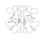
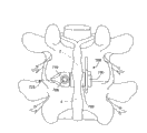
With reference to Fig. 4; In further embodiment, implant 400 according to the present invention can comprise one or two of first engaged element (be also referred to as and rise to the bait) 480 and second engaged element (being also referred to as down hook here) 482 that is used for the curvature movement of constrained motion sections here.For example, similarly hook was authorized the United States Patent(USP) No. 6,451 of Zucherman etc. on JIUYUE 17th, 2002; In 019 with the United States Patent(USP) No. 6 of authorizing Zucherman etc. on November 25th, 2003; More detailed explanation is arranged in 652,527, and these two parts of files are in document is included in as a reference.Can comprise this layout according to implant of the present invention.Implant 400 shown in the Figure 4 and 5 comprises from what pivot was connected to that the upper connecting rod 484 of main body 401 extends rises to the bait 480; Following hook 482 with the lower connecting rod that is connected to main body 401 from pivot 486 extensions.Alternately, connecting rod 484,486 can with main body 401 fixed correlations.Hook 480,482 comprises tapered close end 481,483, and they organize expander to come the upper and lower motion segment interspinous ligament of separate targets motion segment as importing.Along with being positioned between the adjacent spinous when main body 401; Hook 480,482 tapered close ends 481,483 can thrust and/or separate interspinous ligament similarly up and down; Make that hook 480,482 can be located rightly up and down; With when main body 401 is in place, be used for limiting or the curvature movement of constrained objective motion segment.As shown in the figure, hook 480,482 can pivot relatedly with connecting rod 484,486, makes that hook 480,482 can be with respect to connecting rod 484,486 rotations, thereby allows the doctor to improve contact and in hook 480,482 and spinous process 2, distributed load between 4 accordingly.Rotatable upper connecting rod 484 can provide flexible with lower connecting rod 486 in placement; Make when anatomical features in variation between the patient with when between motion segment, changing; The secondary yardstick of implant 400 and principal dimensions are arranged around the longitudinal axis 425 and are changed, thereby can hold implant 400.
Fig. 5 be positioned at adjacent spinous 2, between 4 and have and rise to the bait 480 and the rearview of the implant 400 of following hook 482, wherein said rising to the bait 480 is arranged to as required limit flexion and extends both with following hook 482.And then second alar part 360 launches with restriction implant 400 moving along the longitudinal axis 325.Rising to the bait 480 stops with following hook 482 and to move along the longitudinal axis 325 with the direction in contrast to direction of insertion, lets the first alar part no longer necessity that becomes.
With reference to Fig. 6 A and 6B; In another embodiment; Be used for method and implant 500 that this implant 500 is positioned between the spinous process can be comprised distraction guide 510 according to the present invention; Wherein the part of distraction guide 510 can be extended from distraction guide 510, thereby is positioned at the intracavity of main body 501 through insert 370, and forms the last winglet 512 and following winglet 514 of second alar part 560 respectively.This with the foregoing description in distraction guide integral body form by winglet and contrast.In this embodiment, winglet 512,514 extends the sidepiece of distraction guide 510.When not extending, shown in Fig. 6 A, winglet 512, the 514 local sidepieces that form distraction guide 510.After distraction guide 310 whole expansion (seeing Fig. 2 A to 3B), when hoping that second alar part 560 has limited height as stated with respect to implant 300,400, think that this embodiment is useful.For example, will navigate to the place of adjacent motion segment in implant 500, and for example possibly hope to be applied in the extension movements on the implant 500 when compressive load, second alar part 560 of implant 500 is not interfered with another implant.For above-mentioned implant, those skilled in the art will appreciate that there are many different distortion in the implant 500 among Fig. 6 A and the 6B.For example, in alternate embodiment, last winglet 512 can have some other shapes with following winglet 514.The position of for example going up winglet 512 and following winglet 514 is staggered, and the feasible implant 500 that is positioned at adjacent motion segment can more easily be located and do not interfered with other implants.This staggered state also can hold up and down spinous process one of them than another wide anatomical features.Utilize staggered state, for example go up winglet 512 and can be pivoted on the distraction guide 510, the position is pivoted on position on the distraction guide 510 more near separating end 511 than 514 of following winglets.In another embodiment, last winglet 512 can have some other shapes with following winglet 514.
With reference to Fig. 7 A to 8, in the another kind of embodiment of implant 600 according to the present invention, main body 601 can comprise hollow central body 605 (being shown in Fig. 7 C and 7D), and this centrosome extends from first alar part 630.Rotation distance piece 620 is arranged on around the hollow central body 605.Implant 600 can comprise distance piece 620, and it is similar to the for example distance piece described in Figure 1B.Distraction guide 610 can and can comprise winglet 612 and following winglet 614 from hollow central body 605 extensions; Perhaps both can be related with main body 611 pivots of distraction guide 610 for one of winglet about being somebody's turn to do, and feasible upward winglet 612 and/or following winglet 614 can launch as second alar part 660.With reference to Fig. 7 B, sell 606 bearings in main body 601, last winglet 612 can leave from pivoting each other with following winglet 614, make go up winglet 612 and following winglet 614 restrictions or prevention with in contrast to direction of insertion along the longitudinal axis 625 mobile.Therefore last winglet 612 is used as second alar part 660 with following winglet 614.
With reference to the partial cross section of Fig. 7 C and 7D, in an embodiment, distraction guide 610 can comprise glass portion's structure 616, and it is confirmed size and is arranged to receive pin 606.Bar structure 618,619 can pivot and be connected glass portion's structure 616 and one of last winglet 612 and following winglet 614 or between the two; Make when power is applied to glass portion structure 616 by pin 606; This power further is delivered to winglet 612 and following winglet 614; Cause winglet 612 and following winglet 614 on the hinge that is associated with distraction guide 610 major parts 611 613,615, to pivot, make second alar part 660 launch.Can find out; The pivotal point 613,615 of last winglet 612 and following winglet 614 with respect to the mounting points 617 of bar structure 618,619 near layout; Cause being advanced to a time-out when the pin 606 (seeing Fig. 7 D) that mounting points 617 is inserted into, last winglet 612 leaves from pivoting each other with following winglet 614.In another kind of embodiment, last winglet 612 can pivot with some other mechanism with following winglet 614 and leave.Implant according to the present invention is not intended to be limited to the second alar part development mechanism that specifies here.
With reference to Fig. 8, illustrate implant 600 be positioned at adjacent spinous 2, between 4.As shown in the figure, when being arranged to first structure (that is, as distraction guide 610), the size of second alar part 660 makes that going up winglet 612 can extend in the adjacent tissue with following winglet 614 with hoping.But the size and the moulding of last winglet 612 and following winglet 614 can be different from shown in Figure 8.The size of last winglet 612 and following winglet 614 and moulding only need let winglet 612,614 restrictions up and down or prevention with direction the moving along the longitudinal axis 625 in contrast to direction of insertion when being arranged to second structure.
Fig. 9 A to 9C illustrates the embodiment that is arranged in adjacent spinous 2, the further implant 700 between 4 according to the present invention.In this embodiment; Winglet 712,714 can be arranged in the distraction guide 710 up and down; And can arrange and launch through actuating an actuator; This actuator arranges and comprises the axle that is connected with cam 707 that this has engageable head 706, comprises alternately that perhaps some other mechanism is such as gear.From Fig. 9 A, can find out, implant 700 can be as above with reference to Fig. 3 saidly be arranged in adjacent spinous 2, between 4.The distraction guide 710 of implant 700 can be launched, and is connected adjacent spinous 2, interspinous ligament 6 between 4 to thrust and/or to separate.Implant 700 may be advanced into spinous process 2 then, between 4, makes distraction guide 710 further separate interspinous ligament 6, thereby form the space that distance piece 720 can be arranged.In an illustrated embodiment, distance piece 720 can center on the centrosome pivot that extends from first alar part 730 of implant 700.First alar part 730 restriction and/or stop with direction of insertion moving along the longitudinal axis of implant 700.
In case after implant 700 is arranged as required, can actuate said actuator and arrange and launch up and down winglet 712,714, thereby form second alar part 760 shown in Fig. 9 C.This second alar part 760 restrictions and/or stop with 725 move in contrast to direction of insertion along the longitudinal axis.After second alar part 760 launched, adjacent spinous 2,4 part at least was arranged on alar part 730, between 760, has prevented that implant 700 from undesirably shifting out from adjacent spinous 2, space between 4.Shown in Fig. 9 C; First alar part 730 and second alar part 760 can separate enough far away with arranging; Make adjacent spinous 2,4 can be relative to each other slightly move (for example, laterally---such as in the twist motion process), allow patient that bigger kinematic dexterity is arranged.
Fig. 9 B and 9C are the backsight partial sections of the implant 700 shown in Fig. 9 A.In an embodiment, extensible winglet 712,714 can utilize the actuator that comprises axle 707 and cam 716 to arrange from distraction guide 710 stretching, extensions.Cam 716 can rotate, and outwards pivots from distraction guide 710 to force winglet 712,714.As shown in the figure, the local at least intracavity that is arranged on distraction guide 710 of winglet 712,714.
Figure 10 A to 10E illustrates the further embodiment that is arranged in adjacent spinous 2, the implant between 4 800 according to the present invention.In this embodiment; Winglet 812,814 can be arranged in the distraction guide 810 up and down; And can arrange and launch that this actuator is arranged and comprised the screw 807 with engageable head 806, comprises alternately that perhaps some other mechanism is such as gear through actuating an actuator.From Figure 10 A, can find out, implant 800 can be as above with reference to Fig. 3 saidly be arranged on adjacent spinous 2, between 4.The distraction guide 810 of implant 800 can be used for thrusting and/or separate and be connected adjacent spinous 2, the interspinous ligament between 46.Implant 800 is advanced to spinous process 2 then, between 4, makes distraction guide 810 further separate interspinous ligament 6, thereby form the space of placing distance piece 820.In an illustrated embodiment, distance piece 820 can center on the centrosome pivot that extends from first alar part 830 of implant 800.First alar part 830 restriction and/or stop with direction of insertion moving along the longitudinal axis 825 of implant 800.
In case implant 800 cloth postpone as required can be actuated said actuator and arrange and launch up and down winglet 812,814, thereby formed second alar part 860 shown in Figure 10 B.Second alar part 860 restriction and/or stop with 825 move in contrast to direction of insertion along the longitudinal axis.After second alar part 860 launched, adjacent spinous 2,4 part at least was arranged on alar part 830, between 860, prevents that implant 800 from undesirably shifting out from adjacent spinous 2, space between 4.Shown in Fig. 9 B; First alar part 830 and second alar part 860 can separate enough far away with arranging; Make adjacent spinous 2,4 can be relative to each other slightly move (for example, laterally---such as in the twist motion process), allow patient that bigger kinematic dexterity is arranged.
Figure 10 C and 10D are that the implant 800 shown in Figure 10 A and the 10B is looked closely partial section.In an embodiment, extensible winglet 812,814 can utilize actuator to arrange that from distraction guide 810 stretching, extensions, this actuator is arranged and comprised screw 807 and threaded collar 816.Threaded collar 816 can be driven along screw 807, thereby forces winglet 812,814 outwards to pivot from distraction guide 810.As shown in the figure, the local at least intracavity that is arranged on distraction guide 810 of winglet 812,814.Winglet 812,814 is connected to threaded collar 816 at last pivotal point 817 and following pivotal point 819 pivots.The pin 813,815 or other hinder devices can be arranged on intracavity, and be arranged to let pin 813,815 not can with the layout interference of the winglet that is in embedding, non-expanded position 812,814.But, when threaded collar 816 along screw 807 when fore-and-aft direction is advanced, the inner surface contact plug 813,815 of winglet 812,814, and winglet 812,814 pivots from distraction guide 810 and leaves.If desired, winglet 812,814 can be spring biased against post 813,815, makes that at embedded location with at any expanded position, winglet 812,814 can remain against on the post 813,815.
Shown in Figure 10 D and 10E, when threaded collar 816 when screw 807 is advanced certain distance, winglet 812,814 launches to form second alar part 860.Winglet 812,814 stretches along the major part of spinous process 2,4 outer surfaces.When with in contrast to direction of insertion along the longitudinal axis 825 when advancing, winglet 812,814 contact adjacent spinous 2,4 and resist being moved further along said direction.The end-view of the implant 800 when Figure 10 E is 860 expansion of second alar part.As shown in the figure; The pieceable head 806 of screw extends from distraction guide 810; But; When embodiment, the pieceable head 806 of screw is preferably retreated with the surperficial concordant of distraction guide 810 or from the surface of distraction guide 810 slightly, makes that moving in interspinous ligament 6 and/or spinous process 2,4 separation processes of implant 800 is not interrupted.The pieceable head 806 of screw demonstrates from distraction guide 810 and extends, and is used for explaining possibly arrange with respect to distraction guide 810 close ends.
Figure 11 A and 11B illustrate the another kind of embodiment of the implant 900 with alternative actuator layout.In this embodiment, winglet 912,914 can reverse in layout, and making can be through advancing threaded collar 916 to launch winglet 912,914 towards the pieceable head 806 of screw.Figure 12 A and 12B illustrate the further embodiment of the implant 1000 with alternative actuator layout.In this embodiment, winglet 1012,1014 comprises two hinge portions, and each winglet 1012,1014 is folded-out to form the part of second alar part 1060.Second alar part 1060 can not launch so far away along spine axis, and promptly second alar part 1060 is along the total height of the spinal column embodiment less than the front.The second alar part height shortens, and this is positioned in implant under the situation of adjacent motion segment and has superiority, thereby prevents that adjacent implant from undesirably contacting.
As stated, in according to other embodiments of the invention, winglet can utilize other mechanisms except screw and threaded collar to launch from distraction guide.For example, can use one or more gear.And in other embodiments, the shape of winglet is followed other shapes outside the shape shown in Figure 10 A to 12B up and down.The present invention be not be intended to winglet be limited to such as shown in shape.In further embodiment, such as shown in Figure 13, implant 1100 can only comprise up and down winglet one of them.For example, be positioned in implant under the situation of adjacent motion segment, have following winglet 814 and have superiority, thereby prevent that adjacent implant 1100 from undesirably contacting.For those of ordinary skills, be apparent that, can adopt many different actuators to arrange and form second alar part.Implant according to the present invention is not limited to these implants that specify here.
The material that implant of the present invention is used
In certain embodiments; The assembly of implant and implant (that is, distance piece, distraction guide etc.) can be processed with medical grade metal such as titanium, rustless steel, cobalt chromium, their alloy or other suitable embedded materials with similar high strength and bio-compatible characteristic.In addition, implant is can be at least local to be processed by shape memory metal, Nitinol for example, and this metal is the conjugate of titanium and nickel.This material is that the typical case is radiopaque, and in the angiographic procedure of x-ray imaging and other types, manifests.According to implant of the present invention, and/or its part can also be with some flexible and/or deflectable material process.In these embodiment, implant and/or its part can all perhaps locally be processed with medical grade bioavailable polymer, copolymer, mixture and polymer complex.Copolymer is the polymer that derives from from more than a kind of monomer.Polymer complex is two kinds of perhaps hetero-junctions compounds of multiple material, and wherein component is inconsistent, therefore interface each other, the place of representing.Polymeric blends is two kinds of perhaps macroscopical homogeneous mixtures of multiple not similar polymers.Many polymer, copolymer, mixture and polymer complex are radiolucent, and in the moulding of X ray or other types, do not manifest.The implant that comprises this material can hinder for the doctor brings less observation when radiography than the implant that all comprises the radiopaque material.But implant needn't comprise any radiolucent materials.
Gang's bioavailable polymer is a PAEK family, and this family comprises several members, comprises polyether-ether-ketone (PEEK) and PEKK (PEKK).PEEK is proved to be to be used for the robust materials of implant, and satisfies criterion of biocompatibility.Medical grade PEEK can be from Victrex Corporation ofLancashire, and the product of the PEEK-OPTIMA by name of the product under the Great Britain obtains.The product that medical grade PEKK can be called OXPEKK from the name under the Oxford Performance Materials obtains, and also can obtain from the product of the BioPEKK by name under the CoorsTek.These medical grade material also obtain as the enhanced polymer resin, and this reinforced resins demonstrates the bigger strength of materials.In an embodiment, implant can be processed with PEEK 450G, and this material is unfilled PEEK, is used for medical implant through approval, can obtain from Victrex.Other sources of this material comprise the Gharda that is positioned at India Panoli.PEEK 450G has following approximate characteristic:
Characteristic value
Density 1.3g/cc
Rockwell?M 99
Rockwell?R 126
Hot strength 97MPa
Elastic modelling quantity 3.5GPa
Flexural modulus 4.1Gpa
PEEK 450G has suitable physical mechanical characteristic, and is adapted at bearing between the adjacent spinous and transmitting physics load.Implant and/or its part can through extrude, injection, pressure molding and/or machining technique form.
Should be noted that selected material also can fill.Filler can add polymer, copolymer, polymeric blends or polymer complex to, with reinforced polymeric material.Add filler and change characteristic, such as machinery, optics and thermal characteristics.For example, can add carbon fiber and come mechanically to strengthen this polymer, for special-purpose improves intensity, such as being the load-bearing device.In certain embodiments; Other PEEK of other levels also is available; And be considered as according to implant of the present invention, fill or 30% carbon is filled other PEEK of level such as 30% glass, if this material by FDA or other administrative organizations clearly for can be used for implantable device.With respect to unfilled PEEK, the PEEK that glass is filled has reduced elongation, but has increased the flexural modulus of PEEK.The product of processing is known to be ideal for improving intensity, rigidity or stability.With respect to unfilled PEEK, known compressive strength and the rigidity of PEEK that carbon is filled with lifting, but reduced elongation.The PEEK that carbon is filled also provides wearability and bearing capacity.
Should be appreciated that; Other suitable similar bio-compatible thermoplasticity or thermoplastic condensed polymer's materials also can use, and do not depart from the scope of the present invention, and wherein said material is wanted endurance; Has good memory; But and be flexible and/or deviation, have low-down water absorption and good wear-resisting and/or wear resistence.As mentioned, implant can comprise PEKK (PEKK).Other available materials comprise polyether-ketone (PEK), polyetherketoneetherketoneketone (PEKEKK), and polyether ether ketone ketone (PEEKK), and generally include PAEK.And, also can use other polyether-ketones and other thermoplastics.The list of references that is used for the suitable polymer of implant can be with reference to following file, they all as a reference document be included in this.These files comprise: the open WO02/02158A1 of PCT, open day on January 10th, 2002, subject name " Bio-Compatible Polymeric Materials "; The open WO02/00275A1 of PCT; Open day on January 3rd, 2002, the open WO02/00270A1 of subject name " Bio-Compatible PolymericMaterials " and PCT; Open day on January 3rd, 2002, subject name " Bio-Compatible Polymeric Materials ".Other materials is such as

polycarbonate polyurethane; From Polymer Technology Group; Berkeley; California can obtain; Also be suitable, because it has good oxidation stability, biocompatibility, mechanical strength and wearability.Also can use other thermoplastics and other heavy polymers.
The method of implant between implantation vertebra
Here disclose and instructed the minimum intrusive mood operation method that is used for the implant 300 shown in Fig. 2 A-8 is implanted to cervical vertebra.In the method, shown in figure 14, the cable 780 that preferably leads passes placement network 790 and is inserted in the neck of implant receptor.Guiding cable 780 is used for confirming that implant 300 will comprise where spinous process is placed on respect to cervical vertebra.After in case guiding cable 780 is located under the help of imaging technique; Side cuts at cervical region; Make and to pass this otch and be positioned in the cervical region, and guided in the end of guiding cable 780 along the route that is substantially perpendicular to guiding cable 780 according to the implant 300 of the embodiment of the invention.The main body 301 of implant 300 is inserted in the patient's neck.Preferably during insertion, distraction guide 310 is thrust or is separately organized, and does not cut off tissue.
After main body 301 was located satisfactorily, insert 370 can be positioned at the intracavity of main body 301, caused the distraction guide 310 of main body 301 to be arranged to second structure, made at least a portion of distraction guide 310 form second alar part.Insert 370 can be along the route insertion of the insertion route conllinear of general and main body 301.The anatomical features of cervical region makes that for main body 301 and insert 370, getting into cervical region from sidepiece is most convenient and minimum intrusion.
And, open here and instructed the minimum intrusive mood operation method of will implant shown in Fig. 2 A-8 implanting lumbar vertebra.In the method, the flow chart shown in Figure 15 A preferably can be through front and back near forming monolateral otch or opening (step 102).Monolateral otch can be formed on for example apart from the position along spinous process axis left side certain distance.This otch or opening can enlarge, and separating tool can be positioned in this otch, make that the close end of separating tool can be near the exposed side (step 104) of interspinous ligament.Separating tool can receive and advancing through interspinous ligament, receives implant (step 106) thereby separate interspinous ligament.After interspinous ligament was fully separated, separating tool can be freed and taking-up (step 108) from otch.
In case after separating tool took out from otch, implant can be positioned at the opening part of expansion, and the distraction guide of implant can receive advancing and passes the opening (step 110) of this expansion.Implant can further receive advancing passes this opening, is positioned at as required up to distance piece between the adjacent spinous of targeted motion segment (step 112).Distance piece rotates freely, and makes load more be evenly distributed on the spinous process surface.Randomly, implant can be urged into the opening that passes this expansion, up to the adjacent spinous process of first alar part contact, thereby stops being moved further along direction of insertion.In case after the appropriate layout of implant, insert can be positioned at the distal portion of implant, makes insert to be urged into and gets into and pass the cavity (step 114) of hollow central body.Along with the insert bearing in the intracavity side, distraction guide separately, last winglet and following small span are split into second alar part.The residue instrument can take out from otch, and closed this otch (step 116).Preferably during insertion, separating end thrusts or separately organizes, and can not cut off tissue.
And, open here and instructed the minimum intrusive mood operation method of will implant shown in Fig. 9 A-13 implanting lumbar vertebra.In the method, shown in the flow chart of Figure 15 B, can form otch or opening (step 202) with the front and back method.This otch or opening can enlarge, and separating tool can be positioned in this otch, make that the close end of separating tool can be near the exposed side (step 204) of interspinous ligament.Distraction guide can be urged into passes interspinous ligament and separation, receives implant (step 206) thereby separate interspinous ligament.In case after interspinous ligament was fully separated, implanting instrument can be freed and taking-up (step 208) from otch.
After in case distraction guide is taken out from otch; Implant can be positioned at the opening of this expansion; And the implant distraction guide is urged into the opening (step 210) that passes this expansion, and implant can be passed this opening by further propelling and is positioned at as required up to distance piece between the adjacent spinous of targeted motion segment (step 212).Distance piece rotates freely, and makes load more be evenly distributed on the spinous process surface.Randomly, implant can be urged into the opening that passes this expansion, up to first alar part contact adjacent spinous, thereby stops being moved further along direction of insertion.In case after the appropriate layout of implant, driving tool can be inserted in this otch from the insertion point, is positioned at the relative sidepiece (step 214) of adjacent spinous.Driving tool can mesh actuator and arrange, and can actuate this actuator and arrange, makes that going up winglet launches as second alar part, (step 216) as stated with following winglet.The residue instrument takes out from otch, and this cut closure (step 218).Preferably during insertion, separating end thrusts or separately organizes, and does not cut off tissue.
Above stated specification of the present invention is set forth in order to illustrate with illustrative purposes.It is not intended to exhaustive or limits the invention to disclosed precise forms.For many changes of those skilled in the art and distortion is tangible.Embodiment is selected and explanation is in order to explain principle of the present invention and practical application thereof best, thereby makes those skilled in the art understand different embodiments of the invention, and makes different distortion be suitable for the special purposes of being considered.Be intended to like this explain that scope of the present invention is limited claims and equivalent thereof.