CN100584235C - Molded surface fastener and cushion body formed integrally with the molded surface fastener - Google Patents
Molded surface fastener and cushion body formed integrally with the molded surface fastener Download PDFInfo
- Publication number
- CN100584235C CN100584235C CN200510005808.XA CN200510005808A CN100584235C CN 100584235 C CN100584235 C CN 100584235C CN 200510005808 A CN200510005808 A CN 200510005808A CN 100584235 C CN100584235 C CN 100584235C
- Authority
- CN
- China
- Prior art keywords
- basal component
- surface fastener
- molded surface
- joint element
- lateral sidewall
- Prior art date
- Legal status (The legal status is an assumption and is not a legal conclusion. Google has not performed a legal analysis and makes no representation as to the accuracy of the status listed.)
- Active
Links
Images


Classifications
-
- A—HUMAN NECESSITIES
- A44—HABERDASHERY; JEWELLERY
- A44B—BUTTONS, PINS, BUCKLES, SLIDE FASTENERS, OR THE LIKE
- A44B18/00—Fasteners of the touch-and-close type; Making such fasteners
- A44B18/0069—Details
- A44B18/0076—Adaptations for being fixed to a moulded article during moulding
-
- Y—GENERAL TAGGING OF NEW TECHNOLOGICAL DEVELOPMENTS; GENERAL TAGGING OF CROSS-SECTIONAL TECHNOLOGIES SPANNING OVER SEVERAL SECTIONS OF THE IPC; TECHNICAL SUBJECTS COVERED BY FORMER USPC CROSS-REFERENCE ART COLLECTIONS [XRACs] AND DIGESTS
- Y10—TECHNICAL SUBJECTS COVERED BY FORMER USPC
- Y10T—TECHNICAL SUBJECTS COVERED BY FORMER US CLASSIFICATION
- Y10T24/00—Buckles, buttons, clasps, etc.
- Y10T24/27—Buckles, buttons, clasps, etc. including readily dissociable fastener having numerous, protruding, unitary filaments randomly interlocking with, and simultaneously moving towards, mating structure [e.g., hook-loop type fastener]
- Y10T24/2792—Buckles, buttons, clasps, etc. including readily dissociable fastener having numerous, protruding, unitary filaments randomly interlocking with, and simultaneously moving towards, mating structure [e.g., hook-loop type fastener] having mounting surface and filaments constructed from common piece of material
Abstract
The invention provides a molded surface fastener and a cushion body formed integrally with it wherein a molded surface fastener has first resin invasion preventing means of an expandable resin material for molding a cushion body on each of right and left side edge portions along a longitudinal direction of a thermoplastic-resin base member surface, a number of engaging elements provided between the invasion preventing means, and second resin invasion preventing means for sectioning the engaging elements into desired number of regions along the longitudinal direction of the base member and extending in a width direction between adjacent sectioned regions, the second resin invasion preventing means comprising a function for engaging/disengaging a mating engaging element, thereby the molded surface fastener securing a required binding force.
Description
Technical field
The present invention relates to a kind of surface fastener and prevent intrusion device, above-mentioned surface fastener has some protruding formula joint elements (male engaging elements), described protruding formula joint element is made up of a plurality of hook-shaped products, the recessed formula joint element of ring-type (female engaging elements) of a lip-deep cooperation of above-mentioned hook-shaped its flat base member of product joint, above-mentioned prevent intrusion device at least on the longitudinal direction of basal component along left side and right side edge part, be used for when molded this product, stopping that a kind of molded resin material invades a joint element and form the district.
Background technology
Passenger's seat in automobile or the train, and various sofas and office's seat all have a kind of pad (cushion body) in their skin material inside.As this pad, adopt so-called asbestos or various molding, above-mentioned so-called asbestos are by with the monkey grass of various rigid fibers and flax or synthetic fibers tangle and harden with rubber or analog and to obtain, and above-mentioned molding is made with various expandables materials.These gasket materials have a curved surface, and above-mentioned curved surface comprises convex and the female shapes that satisfies the ergonomics factor, so that keep a kind of posture that is seated, also do not feel tired although described posture is seated for a long time.Make the gasket material that has this complex surface shape in a large number effectively if plan to consider its gasket performance, then require the above-mentioned asbestos of many manufacturing processes not satisfy the demand.In contrast, the pad of various Foamex systems has been extensive use of, because it can be with a procedure manufacturing, and can be easy to obtain diversified shape.That is to say,, simultaneously the expandables pad is molded as a kind of desirable shape when by a kind of expandables material such as a kind of polyurethane resin of sending out are poured into when foaming of inducting in the mould.
Various fiber cloth or natural leather or synthetic leather skin material be applied on the surface that in this way forms and with described surface becomes integral body.For this integration, used wherein a kind of expandables material has been poured into a device in the mould, above-mentioned mould has a kind of skin material that absorbs along die surface, so that when execution is molded, make the rear surface of a pad and skin material form integral body, perhaps use wherein after forming a kind of pad of expandables material, skin material is applied on its surface and the device that is fixed thereon with a mould.
According to above-mentioned a kind of Unitarily molded method, when skin material when the inner surface of mould is installed, it is absorbed device and absorbs.When skin material during along with the areal deformation of the pad with complicated structure, skin material must be material itself have fabulous stretching may.Yet, because a kind of stretch limit that depends on material is arranged,, and up to now, made very big effort between a seat surface and a perimeter side surface so that remedy this phenomenon so a lot of fold tends to especially produce.
In addition, because this Unitarily molded method forms backing material and skin material on their whole surfaces whole, if so for example apply a brute force towards a direction, on the above-mentioned direction between the actual operating period skin material at the surperficial upper deflecting of pad, then between skin material and pad, produce a kind of shearing force, pad usually partly tears and makes then skin material separately.Usually automatically be restricted as the material of skin material so that get rid of the generation of this class fold, and preferably can be between skin material and pad light exercise so that between them, do not apply any excessive power.For this reason, replace making skin material form integral body in molded pad, a kind of method that skin material is applied on the molded in advance pad has become very popular.
Skin material is applied to conventional method on a kind of pad of expandables material system as a kind of being used for, the joint element of surface fastener is formed the surface to be placed and is fixed on the surface portion corresponding to a protrusion at the bottom of the mould of a pad concave surface, so that it is relative with the surface portion that protrudes to make joint element form the surface, in mould, pour into a mould a kind of expandables material then, so that at a kind of foamed state lower mould pad, and simultaneously surface fastener is embedded in the concave surface of pad and becomes integral body with it, and above-mentioned pad has some joint elements that are exposed.When this foaming is molded, prevent that the expandables material from flowing into a joint element and forming the district.To be applied to the surfacing that various materials are made as fluffing woven/knitted fabric, natural leather and synthetic leather with on the molded pad of said method, above-mentioned various materials are made a kind of bag shape, and the shape of described bag is corresponding to the shape of pad.Then, pasting and become whole surface fastener joint element with pad and form the surface,, and preventing the pad rise so that skin material is bonding and fixing along the concave surface of pad with being arranged on recessed formula joint element on rear surface of skin material.
Invade joint element and form the district in order to prevent the expandables material when the molded pad, normally prevent that along the periphery setting of the basal component 102 of a surface fastener 101 the expandables material from invading wall 104,105, so that surround many joint elements 103, for example at United States Patent (USP) the 5th, 061, No. 540 and 5, disclosed reaching as shown in Figure 13 and 14 in 766, No. 723.Same symbol and like numerals will append on corresponding symbol and the label.
On the other hand, recently, the form of a kind of surface fastener with a kind of band formed continuously.Even in this case, also on the width of a surface fastener, prevent from vertically to invade wall along right side and whole formation of left side edge part, so that use and U.S. Patent No. 5,766, identical method in 723 is enclosed in formed many joint elements on the single side of flat base member from right side and left side.Therefore, the intrusion that prevents a kind of expandables material is invaded a joint element formation district from a side direction (width) direction, in addition, along a longitudinal direction joint element is formed the district and carry out segmentation, and one second of formation prevents to invade wall between adjacent segmentation, so that it extends, therefore prevent of length (vertically) the direction intrusion of expandables material from surface fastener on width.Be used for the expandables material and respectively prevent to invade the height of the height setting of wall greater than the joint element that surrounds.
When molded pad, as mentioned above, surface fastener is placed like this, so that joint element forms the surface portion of the protrusion on the aligning mold bottom of surface and is fixed thereon and then, the expandables material is poured in the mould.When cast expandables material, the intrusion of expandables material is by preventing that invading wall stops, describedly prevents to invade wall and holds up the some joint elements that are used for surrounding each segmentation, and therefore, prevents that the expandables material from invading joint element and forming the district.Treat that forming the rear surface and prevent of whole surface fastener by its basal component by molded and pad invades an outer wall surface of wall and be adhered on the pad and with pad and become integral body.So, do not have expandables to invade joint element and form the district, and therefore, exercise a kind of adhesive function of surperficial fastening zone reliably.In order to guarantee a kind of bond strength between pad and the surface fastener, when molded surface fastener, its rear surface forms a kind of surface of injustice, perhaps makes a kind of supatex fabric and rear surface become integral body.
For each joint element being placed and firmly is fixed on a pre-position of the surface portion that protrudes on the mold bottom, usually a permanent magnet is arranged on the base member of surface fastener, perhaps a permanent magnet 108 is embedded in the part corresponding to the mould of a surface fastener placement location, and simultaneously a magnetic 109 is arranged on the basal component of surface fastener, as at United States Patent (USP) 5, such in 766,723.Therefore, by a kind of magnetic pull of utilizing magnet 108 surface fastener 101 is located and is fixed on a placement location place of surface fastener 101 exactly.Permanent magnet or magnetic form the form of a kind of band, wire shape or bar usually, and use a kind of synthetic resin of material as mixing with a kind of ferrite magnet or magnetic powder of excellent elasticity.As magnetic, adopt a kind of thin-band material or wire rod of steel, and in molded surface fastener, this material is embedded in the basal component.
As mentioned above, in U.S. Patent No. 5,061,540 and No.5,766, in 723 disclosed surface fastener expandables material vertically prevent invade wall the basal component joint element form the surface width on form continuously along two lateral edge portions, and prevent that with one side direction from invading wall and being set to along the longitudinal direction of basal component and forming in the segmentation of formed each predetermined number joint element in the surface at the joint element of basal component, so that it forms between adjacent segmentation.This side direction that prevents is invaded wall and always is not limited to one, but can two of parallel formation prevent side direction intrusion wall.Because vertical and side direction prevents to invade the existence of wall, so when the molded pad of foaming, stop from vertical and lateral and invade the expandables material.As a result, stopped that fully the intrusion joint element forms the district.
As mentioned above, in recent years, generally be on the periphery surface by an injection moulding or extrusion molding resin to a mold wheel continuously, monoblock type and form many joint elements continuously on a kind of surface of band-shaped substrate member, above-mentioned mold wheel comprises some die cavitys that are used for molded many joint elements and prevent expandables material intrusion wall, and mold wheel is rotated towards single direction simultaneously.Yet, even the molded surface fastener that obtains in this way is long, but owing to prevent that a kind of interval of side direction intrusion wall is definite according to the external diameter of mold wheel, so should repeat by a kind of compulsory figure at interval.
On the other hand, for example, in passenger's seat of automobile, on a surface of seat, form a kind of surface that comprises the injustice of a suitable curved surface, so that guarantee to think the posture that is seated of the most comfortable from the ergonomics viewpoint.The structure on the surface of this injustice, especially its length are not changeless, but can change.Molded surface fastener becomes integral body along the concave surface part that one of the pad that has a non-planar surface is seated surperficial with a pad.When covering pad with skin material, by add depress will comprise a recessed formula bonding pad of skin material rear surface fovea superior formula joint element form the district with the joint element of surface fastener and be connected, surfacing is installed on the pad, so that it is stretched tightly.
If plan to install a kind of banded molded surface fastener with the said method continuous molding.Its length is different from the length of corresponding pad concave surface part, then long molded surface fastener must be cut into predetermined length before using.Because cutting position at this moment is the length decision according to the concave surface part, so Cutting Length is always not identical.Therefore, surface fastener usually must form cutting in the district by joint element in a segmentation, and above-mentioned segmentation is invaded wall and separated by the side direction that prevents with a predetermined number joint element.If surface fastener is cutting in composition surface forms the district, then the expandables material is invaded a joint element that cuts and is formed the district, and therefore, each joint element in this district is imbedded in the expandables.Therefore, each its function of joint element loss in the zone that expandables is invaded as joint element, and therefore, can not guarantee the bonding force of original needs when a surface fastener is cut into a predetermined length.
Especially, in above-mentioned U.S. Patent No. 5,061,540 and No.5,766, in the 723 disclosed conventional surface fasteners, the formed side direction that prevents is invaded wall and insertion and is prevented that side direction from invading the interval between each adjacent bond element of wall in the adjacent sectional, is generally equal to joint element and forms the interval between formed each joint element in the district.In addition, because in these intervals, do not have the joint element existence and prevent side direction intrusion wall thickness, so do not apply bonding force.As a result, it becomes and more is difficult to obtain desirable bonding force.
Summary of the invention
Therefore, the present invention has reached and has addressed these problems, and an object of the present invention is to provide a kind of banded continuous molding surface fastener, even described surface fastener energy is an optional position cutting in a longitudinal direction, also can form the intrusion of distinguishing to the expandables material to a joint element and be reduced to its minimum level, to guarantee a kind of indispensable bonding force.
Above-mentioned purpose reaches by a kind of molded surface fastener, above-mentioned molded surface fastener comprises: first prevents the resin intrusion device, described first prevents that expandables material that the resin intrusion device is used to stop that molded pad is used from invading the joint element of described molded surface fastener and forming the district, above-mentioned first prevents that the resin intrusion device is arranged on right side and the left side edge part along the longitudinal direction on a basal component surface, and above-mentioned base member is made with thermoplastic resin and is a kind of flat pattern; Several first protruding formula joint elements, the above-mentioned first protruding formula joint element are arranged on the described basal component on the right side first and prevent that the resin intrusion device and the left side first from preventing between the resin intrusion device; Reach second and prevent the resin intrusion device, described second prevents that the resin intrusion device is used for along the longitudinal direction of described basal component the described first protruding formula joint element being segmented into the district of desired number, described second prevents that the resin intrusion device from extending between the adjacent segment identifier on the width of described basal component, when molded described pad, described molded surface fastener and described pad become integral body, it is characterized in that described second prevents that the resin intrusion device has several second protruding formula joint elements.
More particularly, second prevents that the resin intrusion device from comprising a lateral sidewall part and a plurality of engagement head, above-mentioned lateral sidewall part is extended on the width on basal component surface continuously, and above-mentioned a plurality of engagement head is arranged on the head portion of lateral sidewall part, and extends backward and forward from antetheca and back wall surface on the longitudinal direction of basal component.
Preferably, lateral sidewall apart from the height on basal component surface engage the height on first top greater than each of extending from lateral sidewall and the top of a joint element engagement head equaling in a segment identifier, to form apart from the height on basal component surface on engagement head top that sidewall forms apart from the height on basal component surface.
In addition, what wish is, each engagement head is extended towards the back and the front direction of lateral sidewall, so that interconnecting along the width alternating expression on the width on the surface of basal component of flat pattern extended backward and forward, in addition preferably, the some joint elements that form and align on the basal component width in segment identifier link together by its at least a portion side surface that rises part.
According to the present invention, first prevent that the resin intrusion device from comprising the vertical wall part of two row or multi-row along what the longitudinal direction on basal component surface formed on right side and left side edge part, the vertical wall part of above-mentioned two row or multi-row is aligned on the width of basal component at interval, and on the adjacent row between each vertical wall part formed interval form a passage, described passage has predetermined length on the path direction of expandables.Then, preferably, by plurality of gaps with a predetermined spacing separately, the gap arrangement between adjacent respective wall parts is divided on row's direction becomes a kind of hunting dog odontoid to the respective wall of the vertical wall part of two row or multi-row part on the longitudinal direction of basal component.
In addition, preferably, the first wall of the vertical wall part of two row or multi-row is the joint element setting of contiguous plurality of segments partly, the first wall part second prevents the height of the lateral sidewall part of resin intrusion device apart from the basal component surface in fact apart from the height on basal component surface, and be arranged on wherein a part of height of a vertical wall part of first wall portion of external, set the height that is equal to or less than the first wall part.Molded surface fastener with this structure preferably with a kind of automobile seat, the pad of especially a kind of sofa and a kind of office seat becomes integral body.
Molded surface fastener of the present invention preferably comprises a kind of magnetic or a kind of magnet.As a preferred embodiment, a kind of magnetic or a kind of magnet are embedded in the basal component, so that extend continuously on the longitudinal direction of basal component.The invention is not restricted to this embodiment, but allow molded surface fastener a kind of formed resin material with a kind of magnetic or comprise that the pulverulent material of magnetic mixes, or allow resin material with a kind of magnetic or comprise that a kind of pulverulent material of magnetic mixes, and with an exposed portions serve of this compound application molded surface fastener.
Because of the present invention second prevents that the resin intrusion device has several second protruding formula joint elements, can eliminate can see in the prior art owing to preventing that side direction from invading the bonding force that the existence of wall causes and reducing.
Because second prevents that the resin intrusion device from comprising lateral sidewall part and a plurality of engagement head, above-mentioned lateral sidewall part is extended on the width on basal component surface continuously, be arranged on the top section of lateral sidewall part with above-mentioned a plurality of engagement head and on the longitudinal direction of basal component, extend backward and forward from antetheca and back wall surface, invade joint element and form the district so sidewall sections stops expandables, and have that to form in the district the recessed formula joint element on those identical engagement head of formed joint element and skin material rear surface bonding with joint element.Therefore, guarantee required bonding force by finishing usually a non-existent stick portion.
If lateral sidewall part apart from the height setting on basal component surface greater than each joint element that partly extends from lateral sidewall height on high summit, and simultaneously will be on a plurality of engagement head summit that forms on the sidewall sections apart from each joint element engagement head summit that the height setting on basal component surface equals to form in segment identifier apart from the height on basal component surface, then can stop reliably and attempt to invade the expandables that forms the district across the adjacent joint element of sidewall sections by the lateral sidewall part.Simultaneously, also use the joint ratio identical, engage the recessed formula joint element that is arranged on the skin material rear surface with formed each joint element other segment identifiers from each joint element that sidewall sections extends.
If the adjacent engagement head on the basal component width that sidewall sections extends backward and is forward extended alternately backward and forward with respect to width, then with lateral on the direction that engages of the recessed formula joint element that cooperates have both direction, that is forward and backward.As a result, engage than correspondingly increase, and simultaneously, engaging force also improves.In addition, if the wherein successfully combination of at least a portion lateral surface of rise part of the some joint elements that form in segment identifier and aim on the basal component width can prevent effectively that then corresponding joint element from descending towards a lateral.
First prevent that the resin intrusion device from comprising the vertical wall part of two row or multi-row along what the longitudinal direction on basal component surface formed on right side and left side edge part, the vertical wall part of described two row or multi-row is aligned at certain intervals along the width of basal component, and formed interval forms a passage between the corresponding vertical wall part of adjacent row, and described passage has predetermined length on the path direction of expandables.In this case, the vertical wall part of two row or multi-row wherein each wall part of each row is all separated with the spacing of regulation by plurality of gaps on the longitudinal direction of basal component, and the gap arrangement between corresponding partition wall portions adjacent on row's direction becomes the canine tooth shape.As a result, the expandables material passes between the respective row gap between the part of formed interval and longitudinal direction upper partition wall and invades, and it combines and form integral body with partition wall portions, so that flood each partition wall portions.Therefore, because pad and molded surface fastener are by the rear surface with vertically an outer wall section of wall is bonding and they so are bonded into the corresponding partition wall portions of surrounding each row in addition, so the bond strength between pad and the molded surface fastener improves.
Under the first wall situation that partly joint element of contiguous plurality of segments is provided with of the vertical wall part of two row or multi-row, the first wall part equals the height of lateral sidewall part apart from the height on basal component surface, the height of described lateral sidewall part is second to prevent the height of resin intrusion device apart from the basal component surface, and this part height setting that vertical wall part is arranged on the first wall portion of external is the height less than the first wall part, the expandables material that low vertical wall part is invaded surmounts, and covered by the expandables material and become integral body with it, thereby improved the bond strength between pad and the molded surface fastener.
If the magnetic that extends continuously or magnet is imbedded in the basal component and become integral body with it in a longitudinal direction then can utilize a polarity molded surface fastener to be placed and is fixed on pad exactly with surface fastener setting position in the mould.By on the peripheral direction at the part place of a mold wheel, adding a kind of wire or banded magnetic or magnet, then be easy to make magnetic or magnet and molded surface fastener to become integral body.When molded surface fastener is molded continuously, in above-mentioned mold wheel, form basal component.If the basal component of molded surface fastener is thin, then wire or banded magnetic or magnet most likely separate with basal component.Yet magnetic or magnet become whole part place with it basal component thickness increases, and perhaps vertically wall part is holded up on an above-mentioned part, and magnetic or magnet are embedded in the base member fully, so that eliminate possibility separately.If magnet is embedded in the mould, the magnetic powder that then allows to comprise alloy such as iron, cobalt, nickel or analog is blended at least a portion of base member, some joint elements and vertical wall.
When molded surface fastener is placed on the surface of the mould that is used for molded pad, by being arranged on magnet or the magnetic in the die surface securing member and being arranged on a kind of polarity between the magnet in the mould, molded surface fastener can be located exactly and is fixed in the mould.In addition, in the time can sending out the material foaming, prevent that molded surface fastener from moving from its position, and prevent from vertically producing any gap between wall part and sidewall sections and the die surface.
Become whole pad with this molded surface fastener and can guarantee bonding force, and a kind of slight deflection is played response a kind of regulation of skin material.
Description of drawings
Fig. 1 is that part illustrates the pre-view according to one the first described a kind of molded surface fastener of embodiment of the present invention;
Fig. 2 and 3 cutaway view that to be line segment II-II in Fig. 1 and III-III seen on the direction of arrow;
Fig. 4-the 8th, the cutaway view of being seen on the direction of arrow of the line segment IV-IV-IIX-IIX in Fig. 1;
Fig. 9 is that part illustrates the top view according to one the second described a kind of molded surface fastener of embodiment of the present invention;
Figure 10 and 11 cutaway view that to be line segment X-X in Fig. 9 and X1-X1 seen on the direction of arrow;
Figure 12 is the cutaway view that the line segment XII-XII in Fig. 9 is seen on the direction of arrow;
Figure 13 illustrates the fragmentary, perspective view that a surface fastener and a conventional pad become a whole example; And
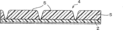
Figure 14 illustrates surface fastener and a conventional pad to become the partial sectional view of another whole example when foaming is molded.
The specific embodiment
Below, specify some embodiments of the present invention with reference to the accompanying drawings.Fig. 1-8 illustrates the first embodiment of the present invention.
As shown in fig. 1, the joint element 3 of a kind of hook-like shapes of many one-tenth joint element except two marginal portions on a surface of the basal component 2 of the flat pattern of the molded surface fastener 1 of the belt like shape of this embodiment forms in the district and forms, the vertical wall part 4 of three rows is holded up, as on two lateral edge portions of basal component 2, preventing the resin intrusion device, so that they become linear parallel ground to arrange along of the present invention first of a longitudinal direction.Shown in Fig. 1-3,6 and 8, these vertical wall parts 4 are made of many partition walls 5, and above-mentioned many partition walls 5 separate with a predetermined pitch (Pitch) in a longitudinal direction.The vertical wall part 4 of three rows is departing from about half pitch aspect their spaced-apart locations, formed gap becomes a kind of canine tooth shape to be arranged between the adjacent row between each partition wall portions 5 in a longitudinal direction.According to this embodiment, as shown in Fig. 1-3 and 7, in a longitudinal direction, some partition wall parts 6 with a lower height, be set at each interval between vertical wall part 4 each row that are arranged to three rows, prevent the resin intrusion device as of the present invention first.
The passage that formed gap was used as a kind of expandables material that injects a mould (not shown) when molded gasket between formed interval and the adjacent partition wall 5 between vertically wall part 4 was respectively arranged.The expandables material forms district's direction around each partition wall portions 5 towards joint element and invades gradually by each gap with at interval from the width of molded surface fastener 1.Arrive at the expandables material before first vertical wall part 4a in a most close joint element formation district, it hardens with a kind of swelling state, and does not arrive joint element formation district.As a result, it is bonding by this way and fixing, so that it surrounds all partition wall portions 5.At this moment,, cross partition wall parts 6, invade the partition wall parts 6 inner formed intervals between vertical wall part 4 then so invade the expandables material of vertical wall part 4 because partition wall parts 6 are lower than partition wall portions 5.As a result, partition wall parts 6 are imbedded in the expandables material.Therefore therefore, partition wall parts 6 are imbedded in the pad, increased constant intensity between molded surface fastener 1 and the pad (not shown) by so-called anchoring effect.
Formed many joint elements 3 are erected in the multirow of the width that strides across basal component 2 in joint element formation district.As shown in fig. 1, by a lateral sidewall part 7 three row's joint elements 3 are defined as a segmentation, described lateral sidewall part 7 is characteristic parts of the present invention.As shown in Fig. 1 and 5, each joint element 3 comprises that all one rises part 3a and an engagement head 3b, above-mentioned rise part 3a upwards rises, and engagement head 3b extends on the longitudinal direction of basal component 2, its front end is to be bent downwardly from the top of rising part 3a simultaneously, thereby a kind of hook of whole formation.In this embodiment, as shown in Fig. 1 and 5, two adjacent on basal component 2 widths joint elements 3 all have engagement head 3b, and described engagement head 3b extends with relative direction with the back in a longitudinal direction forward.The wherein a pair of of these joint elements 3 becomes one by the rise part 3a side surface with same shape.6 pairs of joint elements 3 become delegation to hold up on the width of basal component 2.Certainly, the shape of each joint element 3 is not limited to an example of pointing out and in addition, and the joint element number that becomes delegation to arrange also is not limited to pointed example.
In the lateral sidewall part 7 that is characteristic of the present invention, as Fig. 1, shown in 4 and 5, between vertical wall part of holding up on two lateral edge portions on the width of basal component 2, a lateral sidewall 7a extends across basal component 2 linearities.Lateral sidewall 7a equals the height of vertical wall part 4 from the height on basal component surface, and the maximum height of vertical wall part 4 and lateral sidewall 7a is set the peak height that is a bit larger tham joint element 3 engagement head 3b for.The wherein part of the rise part 8a of joint element 8 has the shape identical with above-mentioned paired joint element 3, and whole joint element head 8b in overall fixed on the longitudinal direction of basal component to the preceding and rear surface of lateral sidewall 7a so that the front end of engagement head 8b separately staggered in the opposite direction towards back and the place ahead to.The height of engagement head 8b equals above-mentioned and forms the height of the engagement head 3b of formed joint element 3 in the district at joint element.
According to this embodiment, the joint element on a lateral edge portions on 3 wire magnetics 9 and basal component 2 widths and the middle body of basal component 2 forms the surface and fuses into integral body so that their in a longitudinal direction wire extend.As wire magnetic 9, the monofilament that adopts a kind of synthetic resin that is mixed with magnetic to constitute, above-mentioned magnetic is made up of a kind of alloy such as iron, cobalt and nickel.According to this embodiment, be to get the surface fastener installed position that a magnet is placed on a mould that is used for molded pad although use above-mentioned linearity magnetic 9, also available shaped like narrow metal forming replaces a thread like body.If do not place magnet, then a wire or banded magnet directly can be fixed on the basal component 2 and replace magnetic at the mould that is used for molded pad.
If wire magnetic 9 a wherein part becomes integral body with basal component 2, so that be exposed on the surface of basal component 2, be used to guarantee a underlying structure intensity, if apply a slight external force, then wire magnetic 9 tends to separate with base member 2.Therefore, according to this embodiment, the becoming whole zone with wire magnetic 9 and form thickly in a longitudinal direction of base member 2.According to this embodiment, as shown in Fig. 2 and 3, thick part on the part of both sides of the edge is formation in the vertical wall 4 of three rows on vertical wall 4 is low than each partition wall parts 6 and basal component 2 widths, has two pairs of joint elements 3 corresponding to one of them the thick part of basal component 2 one of them in the middle body on width of wire magnetic 9.The engagement head 3b that is arranged on two joint elements 3 of these two pairs of joint element 3 outsides extends in the same direction, and two joint elements 3 that are arranged on the middle part extend towards the direction opposite with above-mentioned joint element, and the proximal part that is positioned at two adjacent bond elements 3 at middle part combines with a stop member (block piece) 10 and becomes integral body.
Being arranged on two wire magnetics 9 on the lateral edge portions on basal component 2 widths is separated wall part 5 and partition wall parts 6 respectively and surrounds and become integral body with them, the result is, partition wall portions 5 and partition wall parts 6 form the thick part of basal component 2, separate so that prevent linear magnetic 9 and basal component 2.Therefore, partition wall portions 5 and partition wall parts 6 have be used for stopping the function and the function that is used to prevent that wire magnetic 9 from separating with basal component 2 that the expandables material is invaded when molded pads.On the other hand, the part outer surface that is arranged on the wire magnetic 9 in the middle body on basal component 2 widths is surrounded with the stop member 10 that is connected joint element 3 by two pairs of joint elements 3 and becomes integral body with them.Therefore, the thick part of basal component 2 is formed by two pairs of joint elements 3 and stop member 10, thereby prevents that wire magnetic 9 and basal component 2 from separating.Attract because be fixed to the magnetic pull that wire magnetic 9 on the basal component 2 is fixed to the magnet on the mould (not shown) that is used for molded pad, so become a kind of molded surface fastener 1 of belt like shape accurately and securely to locate and be fixed on the preposition.
Simultaneously, magnetic needs not to be the wire shape, and can be for example a kind of band metal thin plate.Alternatively, this magnetic can separately be fixed.In addition, can be with a magnet without magnetic.For this magnetic or magnet are fixed on the molded surface fastener 1, allow basal surface with magnetic resin such as a kind of resin adhesive that mixes with magnetic or lacquer type organic coating coated substrate member 2, on basal component 2, form a magnetic film layers, perhaps by magnetic is mixed into basal component 2, joint element 3, vertically wall part 4 and lateral sidewall part 7 form the superimposed laminate layers in surface in one of them, perhaps a kind of resin bed that contains magnetic is laminated on the top surface of lateral sidewall part 7.As mentioned above, these processing are not limited to magnetic, and can handle equally magnet.
A kind of continuous notes mouth that is used for molten resin is provided, so that relative with the periphery surface of a mold wheel (die wheel), above-mentioned mold wheel is rotated towards single direction.Many die cavitys that are used to form joint element form in the central area of mold wheel periphery surface, and are used to form partition wall portions 5 and partition wall parts 6 are forming on two lateral edge portions on the axial direction of periphery surface, so that they extend intermittently.In addition, being used to form plurality of side forms therein in the zone of each joint element with die cavity to a plurality of die cavitys of wall part 7 and forms.The die cavity that is used for lateral sidewall part 7 is parallel to a rotation extension of mold wheel with a predetermined phase angle on peripheral direction.On the other hand, the part without interruption that will be used for wire magnetic 9 is arranged on a peripheral part upstream side place of mold wheel on the direction of rotation relative with annotating mouth.Then, wire magnetic 9 is fed on the position relative with mould alternate water injection mouth from supply section continuously.At the inner supply coolant of mold wheel, so that always cooling die is taken turns.In addition, following half part with this mold wheel immerses in the cooling bath described below.
In a kind of continuous manufacturing apparatus of molded surface fastener, a kind of molten resin material is expelled on the periphery surface of mold wheel continuously from continuous notes mouth with said structure.At this moment, mold wheel is rotated towards single direction, and the basal component 2 of surface fastener is formed by the molten resin on the periphery surface in the gap that is injected between mouth and the mold wheel.Simultaneously, each joint element 3, vertical wall part 4, partition wall parts 6 and sidewall sections 7 one after the other use die cavity separately to form.This when molded, each wire magnetic 9 on the mold wheel direction of rotation with respect to being added to injection position from the upstream side of annotating the moulded resin injection direction that mouth injects.According to this embodiment, because 2/3 being exposed on the surface of base member 2 basically of each wire magnetic 9, so except above-mentioned die cavity, form 3 gathering sills that are used for wire magnetic 9 on the peripheral direction in the mold wheel periphery surface continuously.
Therefore, in basal component 2 surfaces of the molded surface fastener 1 that becomes a kind of continuous belt like shape also to form in a manner described, surface with the some joint elements that form thereon, be the lower face that following 1/3 of each wire magnetic is embedded in basal component 2, a top surface of each wire magnetic 9 is partly used joint element 3, vertically one of them covering of wall part 4, partition wall parts 6 and lateral sidewall part 7.When molded above-mentioned molded surface fastener, each wire magnetic 9 is fixed on the surface of basal component 2 continuously simultaneously, and becomes integral body with the surface of described basal component 2.Molded surface fastener 1 is supported by the periphery surface of mold wheel, and carries half turn under a commentaries on classics situation of mold wheel.When carrying, its cooling and sclerosis separate with this periphery surface by the periphery surface that tightens up roller cooling and sclerosis mold wheel, are transported to a winding process subsequently then.
In above-mentioned example, the joint element of basal component 2 forms the surperficial 2a that surperficial rear surface forms a kind of injustice.The reason of doing like this is the bond area that increases Foamex, so that strengthen a kind of bonding force.Uneven surperficial 2a can be easy to form by a backer roll (not shown) that has a large amount of unevenness (uneveness) in its periphery surface is installed by this way, so that backer roll is relative with the periphery surface of mold wheel by molded surface fastener after molded.Although backer roll can be along with the mobile rotation of molded surface fastener, it is synchronous to be more preferably the rotary speed that drives it and mold wheel.Certainly, the rear surface can form smooth rather than uneven surperficial 2a.
In order to make molded surface fastener of the present invention 1 become integral body with a pad (not shown) of making by the expandables material by this method manufacturing, a kind of molded surface fastener 1 of growing continuous band-shaped shape is cut into desirable length, and the segmentation of cutting placed like this, so that the surface portion of the protrusion of the surface that each joint element 3 forms thereon in a mould (not shown), the surface portion of described protrusion is corresponding with a concave portions in the pad.A magnet (not shown) is embedded in the surface portion of mould protrusion, if and molded surface fastener 1 is placed on the surface portion of protrusion, then by a gravitational attraction of magnet, a kind of desirable posture of molded surface fastener 1 usefulness absorbs and is fixed on the surface portion of protrusion molded surface fastener 1 automatically then by wire magnetic 9.
A kind of expandables material is poured in the mould, and flow to each vertical wall part 4 and lateral sidewall part 7 of molded surface fastener 1 from the rear surface, be dispersed on the whole surface of mould, and foaming beginning simultaneously.At this moment, molded surface fastener 1 is located owing to the gravitation of magnet in the mould and is fixed, and its position flowing and can send out pressure and move because of the expandables material not.Although a kind of fluid inflatable resin material attempts to pass gap between each partition wall 5 of vertical wall part 4 of being made up of many rows and the gap between aforesaid each partition wall parts 6, invade the formation district of joint element 3 from the width of die surface securing member 1, but it is separated wall part 5 and partition wall parts 6 block, and therefore finishes its foaming and sclerosis before arriving joint element formation district.On the other hand, with regard to the longitudinal direction of molded surface fastener 1, a kind of molded surface fastener that obtains 1 must be cut into a predetermined length, as mentioned above.If lateral sidewall part 7 can be cut into two sections in a longitudinal direction at that time, then it is desirable.Yet required cutting part length is always not identical.In addition, in the surface fastener that forms continuously as mentioned above, the interval between each lateral sidewall part 7 can not change arbitrarily.Therefore, molded surface fastener 1 usually is to cut in the formation district of joint element 3.
As a result, all the other districts that wherein only form joint element 3 under without any the situation of lateral sidewall part 7 exist on shearing end one side of the molded surface fastener of cutting.Yet,, can prevent to influence the whole length of the molded surface fastener of incision if regulate interval between the lateral sidewall part 7.If in mould, place and the fixing molded surface fastener 1 that cuts after, pour into a mould the expandables material as mentioned above, then the expandables material is invaded all the other districts, joint element 3 exists by an incision end of molded surface fastener in described all the other districts, and arrives a nearest lateral sidewall part 7 sometimes.Because this intrusion, the joint element 3 that exists in all the other districts is imbedded the internal structure of a foaming body, and becomes integral body with the internal structure of described foaming body.
As a result, owing to the constant intensity of 1 pair of pad of molded surface fastener is strengthened by anchorage effect, so the joint element that exists in all the other districts is useful.The expandables material prevents by lateral sidewall part 7 further mobile after arriving lateral sidewall part 7, and therefore, it does not arrive in the joint element formation district by each joint element of vertical wall part 4 and 7 encirclements of lateral sidewall part.After molded surface fastener 1 was fixed to a desirable place and becomes integral body with it, pad was used according to the described skin material of a kind of prescriptive procedure and is covered.By compressing a mounting portion of molded surface fastener, the recessed formula joint element on the molded surface fastener table of joint leather material rear surface so that skin material does not rise from pad, thereby accurately and is suitably installed along the curved surface of pad.
In the present invention,, but on its top surface, have the joint element 8 of some one-tenth hook-like shapes because lateral sidewall part 7 is not a kind of simple wall, thus the district of no any joint element be provided with, and unlike conventional molded surface fastener.Therefore, the almost whole surface of molded surface fastener 1 all is bonded on the recessed formula joint element that forms on skin material (the surface skin material) rear surface, so bond strength obviously improves.As a result, even on yawing moment a power is applied in the seat segmentation of skin material, skin material also is not easy to take apart.In addition, combine the light exercise that can adapt between skin material and the pad between molded surface fastener 1 and the skin material, and close differently with a kind of high strength yarn or toe-in, and therefore protect pad to avoid damage.
Fig. 9-12 illustrates one second embodiment of the present invention.This second embodiment is different with the configuration aspects of paired partition wall parts 6 that are provided with of first embodiment and joint element 3, and promptly their broad ways are arranged.Since another kind of structure basically with first embodiment invariably with, so in the following description, utilize with first embodiment in identical title and the title and the label of some elements of label conduct except different elements.
According to this embodiment, replace partition wall parts 6, form a stop member 11, described stop member 11 equals stop member 10, be used to connect two pairs of joint elements 3, described two pairs of joint elements 3 are arranged in the middle body on molded surface fastener 1 width of first embodiment.As shown in Fig. 9 and 11, the ragged edge of three vertical wall parts 4 and the inside last two arrange partition wall portions 5 and lateral sidewall part 7 usefulness one first stop member 11 links together, above-mentioned three vertical wall parts 4 are positioned on the extension that joint element 3 extends on basal component 2 widths, in addition, three row's partition wall portions, 5 usefulness, one second stop member 11 is linked together.Stop member 11 is embedded in the pad, so that the partition wall parts 6 in first embodiment owing to anchorage effect increases the constant intensity of molded surface fastener 1, and prevent that wire magnetic 9 and basal component 2 from separating.
According to first embodiment, provide separately along the paired joint element 3 that is provided with of the width of basal component 2.According to this embodiment, as shown in Fig. 9 and 10, the side surface that each joint element 3 that is provided with in pairs along the width of basal component 2 rises part combines with ribs 12 and becomes integral body.If 3 pairs of joint elements that are arranged on basal component 2 widths mutually combine with ribs 12 by this way, then when the skin material (not shown) is pushed down the joint element formation district of molded surface fastener 1, each joint element 3 can not fall towards the side, and its setting projection posture is not subsided.As a result, each joint element 3 is engaged recessed formula joint element mostly and catches, and has increased the joint ratio, causes engaging force to increase.
Other operations are identical with first embodiment with effect.When molded surface fastener 1 when mold formed and pad when becoming integral body, the joint element formation that prevents the molded surface fastener 1 that the vertical wall part 4 of expandables material intrusion quilt surrounds is distinguished, and above-mentioned vertical wall part 4 forms on molded surface fastener 1 with the peculiar a kind of structure of the present invention and lateral sidewall part 7.In addition, eliminate on the main composition surface of molded surface fastener a kind of joint element with the engagement head 8b of lateral sidewall part 7 integrally formed surface fasteners and omitted the generation of segmentation, thereby improved bond strength with skin material greatly.
Representative embodiment more of the present invention have been described above.Yet, the invention is not restricted to pointed example, for example, it can adopt the known structure that is used for joint element of various routines, can in the surface of basal component, form groove with it, and each joint element is risen from the basal surface of groove, so that guarantee the elasticity of molded surface fastener and therefore reduced each joint element, vertical wall part and lateral sidewall height partly, thereby reduced the thickness of whole molded surface fastener.
Claims (13)
1. a molded surface fastener (1) comprising:
First prevents resin intrusion device (4), described first prevents that expandables material that resin intrusion device (4) is used to stop that molded pad is used from invading the joint element of described molded surface fastener and forming the district, described first prevents that resin intrusion device (4) is arranged on right side and the left side edge part along the longitudinal direction on the surface of a basal component (2), and above-mentioned basal component (2) is to make and be a kind of flat pattern with thermoplastic resin;
Several first protruding formula joint elements (3), the described first protruding formula joint element (3) are arranged on described basal component (2) and go up on the right side first and prevent that the resin intrusion device and the left side first from preventing between the resin intrusion device;
With second prevent resin intrusion device (7), described second prevents that resin intrusion device (7) is used for along the longitudinal direction of described basal component (2) the described first protruding formula joint element (3) being segmented into the district of desired quantity, described second prevents that resin intrusion device (7) width along described basal component (2) between the district of adjacent segmentation from extending, when molded described pad, described molded surface fastener (1) becomes integral body with described pad, it is characterized in that:
Described second prevents that resin intrusion device (7) has several second protruding formula joint elements (8).
2. according to the described molded surface fastener of claim 1 (1), it is characterized in that: second prevents that the resin intrusion device from comprising lateral sidewall part (7), and described lateral sidewall part (7) is extended on the width on basal component surface continuously, and
Lateral sidewall part (7) has lateral sidewall (7a) and a plurality of engagement head (8b), and described a plurality of engagement head (8b) are extended towards front and posterior direction from the preceding and back wall surface of lateral sidewall (7a).
3. according to the described molded surface fastener of claim 2 (1), it is characterized in that: lateral sidewall (7a) is apart from the height on the basal component surface height greater than the peak of each engagement head (8b) of extending from lateral sidewall (7a).
4. according to the described molded surface fastener of claim 2 (1), it is characterized in that: equal from the surperficial height of engagement head (3b) peak of formed joint element (3) a segment identifier of basal component from the height of going up the peak of formed each engagement head (8b) at lateral sidewall (7a) on basal component surface.
5. according to the described molded surface fastener of claim 2 (1), it is characterized in that: engagement head (8b) is so extended on the front and back direction of lateral sidewall (7a), so that adjoin each other on the width on basal component surface, above-mentioned each engagement head (8b) is extended alternately backward and forward along width.
6. according to the described molded surface fastener of claim 1 (1), it is characterized in that: in a segment identifier, form and the joint element (3) that is in line on the width of basal component (2) is holded up one after the other linking together to the small part side surface of part (3a) by them.
7. according to the described molded surface fastener of claim 1 (1), it is characterized in that: on right side and left side edge part, formed first prevent that the resin intrusion device from comprising vertical wall part (4) that two row or multi-row are aligned at interval on the width of basal component (2) along the longitudinal direction on basal component surface, and formed interval forms a passage between the vertical wall part (4) on the adjacent row, and described passage has predetermined length on the path direction of expandables.
8. according to the described molded surface fastener of claim 7 (1), it is characterized in that: each wall part of the vertical wall part of two row or multi-row (4) on the longitudinal direction of basal component (2) with a predetermined pitch by separated, and the gap between the adjacent partition wall portions (5) on row's direction is arranged into a kind of canine tooth shape between each row.
9. according to claim 7 or 8 described molded surface fasteners (1), it is characterized in that: the joint element setting of the contiguous segmentation of first wall part (4a) of the vertical wall part of two row or multi-row (4); Equal from the lateral sidewall on the basal component surface height of (7) partly from the height of the first wall part (4a) on basal component surface, above-mentioned lateral sidewall partly (7) is described second to prevent the resin intrusion device; The height setting that is arranged on the outside partition wall parts (6) of first wall (4a) and the part of vertical wall part (4) becomes to be lower than the partly height of (4a) of first wall.
10. according to the described molded surface fastener of claim 1 (1), it is characterized in that: molded surface fastener (1) comprises magnetic or magnet.
11. according to the described molded surface fastener of claim 10 (1), it is characterized in that: magnetic (9) is embedded in the basal component (2), so that extend continuously on the longitudinal direction of basal component (2).
12. according to the described molded surface fastener of claim 10 (1), it is characterized in that: magnet is embedded in the basal component (2), so that extend continuously on the longitudinal direction of basal component (2).
13. a pad is characterized in that: described pad with form according to claim 10 or 11 described molded surface fasteners (1) are whole.
Applications Claiming Priority (2)
| Application Number | Priority Date | Filing Date | Title |
|---|---|---|---|
| JP2004019693A JP3886971B2 (en) | 2004-01-28 | 2004-01-28 | Cushion body molded and integrated with the same surface fastener |
| JP2004019693 | 2004-01-28 |
Publications (2)
| Publication Number | Publication Date |
|---|---|
| CN1647712A CN1647712A (en) | 2005-08-03 |
| CN100584235C true CN100584235C (en) | 2010-01-27 |
Family
ID=34214301
Family Applications (1)
| Application Number | Title | Priority Date | Filing Date |
|---|---|---|---|
| CN200510005808.XA Active CN100584235C (en) | 2004-01-28 | 2005-01-27 | Molded surface fastener and cushion body formed integrally with the molded surface fastener |
Country Status (4)
| Country | Link |
|---|---|
| US (1) | US20050160534A1 (en) |
| JP (1) | JP3886971B2 (en) |
| CN (1) | CN100584235C (en) |
| GB (1) | GB2410528B (en) |
Cited By (1)
| Publication number | Priority date | Publication date | Assignee | Title |
|---|---|---|---|---|
| CN104114410A (en) * | 2011-12-13 | 2014-10-22 | 维尔克工业有限公司 | Mold-in touch fastening product |
Families Citing this family (25)
| Publication number | Priority date | Publication date | Assignee | Title |
|---|---|---|---|---|
| US20070101557A1 (en) * | 2005-11-07 | 2007-05-10 | Gallant Christopher M | Bendable fastener strips |
| US7493676B2 (en) | 2006-04-13 | 2009-02-24 | Ykk Corporation | Hook fastener structures |
| WO2010016122A1 (en) * | 2008-08-06 | 2010-02-11 | Ykk株式会社 | Molded hook surface fastener |
| CN102202539B (en) * | 2008-11-06 | 2014-07-16 | Ykk株式会社 | Molding male surface fastener |
| US7998548B2 (en) * | 2009-01-19 | 2011-08-16 | Ykk Corporation | Male surface fastener member for use in a cushion body mold and manufacturing method thereof |
| ES2396832B1 (en) * | 2009-06-17 | 2013-11-18 | Ykk Corporation | MOLDED MALE SURFACE HOLDING ELEMENT. |
| KR101159622B1 (en) | 2009-12-18 | 2012-06-27 | 풍국기업 주식회사 | A fastener assembly having a cover constituted of multi-layer |
| CN104757749B (en) * | 2010-08-23 | 2017-06-23 | Ykk株式会社 | Forming face slide fastener |
| US9271546B2 (en) | 2010-08-23 | 2016-03-01 | Ykk Corporation | Molding hook and loop fastener |
| WO2012120618A1 (en) * | 2011-03-07 | 2012-09-13 | Ykk株式会社 | Molded hook and loop fastener |
| CN104053376B (en) * | 2011-10-26 | 2016-06-15 | Ykk株式会社 | Profiled surface hasp |
| EP2941978B1 (en) * | 2013-01-07 | 2017-11-15 | YKK Corporation | Molded planar fastener and production method for cushion body |
| JP5709953B2 (en) * | 2013-09-19 | 2015-04-30 | Ykk株式会社 | Manufacturing method of molded surface fastener |
| US9504296B2 (en) | 2013-12-18 | 2016-11-29 | Velcro BVBA | Mold-in touch fastening product |
| US9635910B2 (en) * | 2015-04-28 | 2017-05-02 | Velcro BVBA | Mold-in touch fastener systems with wave-shaped wall |
| US9138032B1 (en) | 2015-04-28 | 2015-09-22 | Velcro Industries B.V. | Mold-in touch fastener systems with wave-shaped wall |
| US9826801B2 (en) | 2015-06-17 | 2017-11-28 | Velcro BVBA | Mold-in touch fastening product |
| US9918526B2 (en) | 2015-06-17 | 2018-03-20 | Velcro BVBA | Mold-in touch fastening product |
| US10548374B2 (en) | 2015-07-17 | 2020-02-04 | Ykk Corporation | Fastening tape with flexibility in the longitudinal direction and associated methods |
| US10189387B2 (en) | 2015-07-17 | 2019-01-29 | Ykk Corporation | Fastening tape with flexibility in the lateral direction and associated methods |
| KR101744495B1 (en) * | 2016-01-04 | 2017-06-08 | 원평산업 주식회사 | Fastener manufacturing apparatus |
| JP2017169616A (en) * | 2016-03-18 | 2017-09-28 | スリーエム イノベイティブ プロパティズ カンパニー | Surface fastener member and method for manufacturing the same |
| TWI655123B (en) * | 2018-08-10 | 2019-04-01 | 台灣百和工業股份有限公司 | Injection hook type seat cover fixing strip structure for seat foam |
| US11160381B2 (en) * | 2019-01-29 | 2021-11-02 | Vanco Products LLC | Removable cushion for a chair, mold for making a cushion and a chair having a removable cushion |
| JP7123990B2 (en) | 2019-04-17 | 2022-08-23 | Ykk株式会社 | fastening tape |
Citations (3)
| Publication number | Priority date | Publication date | Assignee | Title |
|---|---|---|---|---|
| US5606781A (en) * | 1995-02-17 | 1997-03-04 | Velcro Industries, B.V. | Separable fastener having a bald perimeter rib bounded by fastening elements |
| US5930876A (en) * | 1996-05-31 | 1999-08-03 | Ykk Corporation | Biodegradable separable fastener and method for production thereof |
| CN1340319A (en) * | 2000-06-30 | 2002-03-20 | Ykk株式会社 | Surfacial hooked buckle |
Family Cites Families (2)
| Publication number | Priority date | Publication date | Assignee | Title |
|---|---|---|---|---|
| AU589770B2 (en) * | 1986-06-20 | 1989-10-19 | Minnesota Mining And Manufacturing Company | Fastener assembly with peripheral temporary attachment layer |
| US6720059B2 (en) * | 2001-05-04 | 2004-04-13 | Ykk Corporation | Fastener strip having vertical sealing members l |
-
2004
- 2004-01-28 JP JP2004019693A patent/JP3886971B2/en not_active Expired - Lifetime
-
2005
- 2005-01-07 GB GB0500280A patent/GB2410528B/en active Active
- 2005-01-26 US US11/043,339 patent/US20050160534A1/en not_active Abandoned
- 2005-01-27 CN CN200510005808.XA patent/CN100584235C/en active Active
Patent Citations (3)
| Publication number | Priority date | Publication date | Assignee | Title |
|---|---|---|---|---|
| US5606781A (en) * | 1995-02-17 | 1997-03-04 | Velcro Industries, B.V. | Separable fastener having a bald perimeter rib bounded by fastening elements |
| US5930876A (en) * | 1996-05-31 | 1999-08-03 | Ykk Corporation | Biodegradable separable fastener and method for production thereof |
| CN1340319A (en) * | 2000-06-30 | 2002-03-20 | Ykk株式会社 | Surfacial hooked buckle |
Cited By (2)
| Publication number | Priority date | Publication date | Assignee | Title |
|---|---|---|---|---|
| CN104114410A (en) * | 2011-12-13 | 2014-10-22 | 维尔克工业有限公司 | Mold-in touch fastening product |
| CN104114410B (en) * | 2011-12-13 | 2016-12-21 | 维尔克有限公司 | In-molded contact secured product |
Also Published As
| Publication number | Publication date |
|---|---|
| JP2005211198A (en) | 2005-08-11 |
| CN1647712A (en) | 2005-08-03 |
| GB2410528A (en) | 2005-08-03 |
| GB2410528B (en) | 2006-03-29 |
| GB0500280D0 (en) | 2005-02-16 |
| US20050160534A1 (en) | 2005-07-28 |
| JP3886971B2 (en) | 2007-02-28 |
Similar Documents
| Publication | Publication Date | Title |
|---|---|---|
| CN100584235C (en) | Molded surface fastener and cushion body formed integrally with the molded surface fastener | |
| US11141899B2 (en) | Molding hook and loop fastener | |
| US7048818B2 (en) | Hook and loop fastening | |
| CN102712274B (en) | Releasable clamp device along convex tendon | |
| US8512845B2 (en) | Molded male surface fastener | |
| KR101151541B1 (en) | Male surface fastener member for use in a cushion body mold and manufacturing method thereof | |
| US7488527B2 (en) | Molded touch fasteners | |
| US9271547B2 (en) | Molded hook and loop fastener | |
| US8658068B2 (en) | Touch fastener products | |
| US11051590B2 (en) | Molded surface fastener | |
| US6828004B2 (en) | Connected fastening members and process for production of resin molded article with fastening member | |
| JP2566609B2 (en) | Method for manufacturing surface fastener member | |
| EP3973811A1 (en) | Hook-and-loop fastener-equipped resin molded body, method for manufacturing same, and method for fixing automobile ceiling material to vehicle body | |
| JP2014188179A (en) | Sheet having inclined stems on both sides and seat using the same | |
| JP2012102579A (en) | Rubber chip sheet |
Legal Events
| Date | Code | Title | Description |
|---|---|---|---|
| C06 | Publication | ||
| PB01 | Publication | ||
| C10 | Entry into substantive examination | ||
| SE01 | Entry into force of request for substantive examination | ||
| C14 | Grant of patent or utility model | ||
| GR01 | Patent grant |