CN100573417C - Find the method and system of the power supply on the external bus - Google Patents
Find the method and system of the power supply on the external bus Download PDFInfo
- Publication number
- CN100573417C CN100573417C CNB2005800241789A CN200580024178A CN100573417C CN 100573417 C CN100573417 C CN 100573417C CN B2005800241789 A CNB2005800241789 A CN B2005800241789A CN 200580024178 A CN200580024178 A CN 200580024178A CN 100573417 C CN100573417 C CN 100573417C
- Authority
- CN
- China
- Prior art keywords
- electronic equipment
- power
- power supply
- external bus
- battery
- Prior art date
- Legal status (The legal status is an assumption and is not a legal conclusion. Google has not performed a legal analysis and makes no representation as to the accuracy of the status listed.)
- Active
Links
Images


Classifications
-
- G—PHYSICS
- G06—COMPUTING; CALCULATING OR COUNTING
- G06F—ELECTRIC DIGITAL DATA PROCESSING
- G06F1/00—Details not covered by groups G06F3/00 - G06F13/00 and G06F21/00
- G06F1/26—Power supply means, e.g. regulation thereof
- G06F1/266—Arrangements to supply power to external peripherals either directly from the computer or under computer control, e.g. supply of power through the communication port, computer controlled power-strips
-
- G—PHYSICS
- G06—COMPUTING; CALCULATING OR COUNTING
- G06F—ELECTRIC DIGITAL DATA PROCESSING
- G06F1/00—Details not covered by groups G06F3/00 - G06F13/00 and G06F21/00
- G06F1/26—Power supply means, e.g. regulation thereof
-
- G—PHYSICS
- G06—COMPUTING; CALCULATING OR COUNTING
- G06F—ELECTRIC DIGITAL DATA PROCESSING
- G06F1/00—Details not covered by groups G06F3/00 - G06F13/00 and G06F21/00
- G06F1/26—Power supply means, e.g. regulation thereof
- G06F1/30—Means for acting in the event of power-supply failure or interruption, e.g. power-supply fluctuations
Abstract
Disclosing the power supply on the identification external bus and/or determined can be from the improvement technology of the electric energy of power supply acquisition by external bus.In general, external bus is by the cable support that is connected between main equipment and the electronic equipment.In this case, main equipment is power supply (for example, power supply adaptor or electric battery), and cable is used to electric energy is offered electronic equipment from power supply.Thereby, can be by understanding from the electric energy of power supply acquisition, electronic equipment can be managed the utilization of its electric energy, so that work according to stable and reliable mode.Electronic equipment is a portable computing device for example.The example of portable computing device comprises portable digital assistant (PDA) and portable electronic device.
Description
Technical field
The present invention relates to electronic equipment, more particularly, relate to the electronic equipment that can couple with external bus.
Background technology
Portable electric appts, battery-powered usually such as portable digital assistant and media player.These electronic equipments also have the external bus port that can support external bus sometimes, such as USB (universal serial bus) (USB) or FIREWIRE (IEEE 1394) bus port.External bus is used to provide the data communication with electronic equipment, and provides a limited number of electric energy to electronic equipment.
Recently,
 (by the media player of the Apple of California Cupertino exploitation) can be by the electric power that provides to its FIREWIRE bus port to its battery charge.Though to battery charge or convenient to the electronic equipment supply of electrical energy in other mode, the external bus purpose is not to be used to transmit a large amount of electric energy by external bus.With regard to usb bus, available electric energy is limited to about 0.5 watt, but process can be increased to about 2.5 watts through consultation.Unfortunately, negotiations process not only bothers, and the quantity of electric energy (even being increased through consultation) remains not enough usually concerning many electronic equipments.
Thereby, need to promote by external bus to the bigger electric energy of electronic equipment output.
Summary of the invention
In general, the present invention relates to discern the power supply on the external bus and/or determine can be from the improvement technology of the electric energy of power supply acquisition by external bus.External bus is generally by the cable support that is connected between main equipment and the electronic equipment.In this case, main equipment is power supply (for example, power supply adaptor or electric battery), and cable is used to electric energy is offered electronic equipment from power supply.Thereby, can be by understanding from the electric energy of power supply acquisition, electronic equipment can be managed the utilization of its electric energy, so that work according to stable and reliable mode.Electronic equipment is a portable computing device for example.The example of portable computing device comprises portable digital assistant (PDA) and portable electronic device.
The present invention can realize with numerous modes, comprises the method for being embodied as, system, device, equipment or computer-readable medium.Several embodiments of the present invention are discussed below.
As electronic equipment, one embodiment of the present of invention comprise at least: with the bus interface that Bussing connector couples, Bussing connector provides power transmission line (power line), ground wire and a plurality of data line to bus interface; The available power detector that is connected with bus interface in the operation, wherein, when power supply was connected with bus interface by Bussing connector in operation, available power detector read voltage level on described a plurality of data line with the available power level of detection from power transmission line; Power consumption Circuits System (circuitry); Go up the power supervisor that is connected with the power consumption Circuits System with the available electrical energy connector with operation, wherein, power supervisor is managed the utilization of power of the power consumption Circuits System of at least a portion according to available power level.
The method of utilization of power that has the electronic equipment of Bussing connector as management, an embodiment comprises following actions at least: detect being connected of Bussing connector of external bus and electronic equipment, described external bus has power transmission line and multiple bus data line at least; When described detection motion detection arrives the connection of external bus, read the voltage level (voltage level) on the described multiple bus data line; According to described voltage level, determining provides whether the main equipment of external bus is power supply adaptor; When definite main equipment is power supply adaptor,, determine the available power level of power supply adaptor according to described voltage level; With available power level according to power supply adaptor, the utilization of power of managing electronic equipment.
The method of utilization of power that has the electronic equipment of Bussing connector as management, another embodiment comprises following actions at least: detect being connected of Bussing connector of external bus and electronic equipment, described external bus has power transmission line and multiple bus data line at least; When described detection motion detection arrives the connection of external bus, read the voltage level on the described multiple bus data line; According to described voltage level, determining provides whether the main equipment of external bus is electric battery; When definite main equipment is electric battery,, determine the available power level of electric battery according to described voltage level; With available power level according to electric battery, the utilization of power of managing electronic equipment.
As the method for determining from the power availability of the power supply adaptor that couples by external bus and electronic equipment, described external bus has power transmission line and multiple bus data line at least, and one embodiment of the present of invention comprise following actions at least: read the voltage level that power supply adaptor is responded on described multiple bus data line; With according to described voltage level, determine the available power level of power supply adaptor.
As the method for determining from the power availability of the electric battery that couples by external bus and electronic equipment, described external bus has power transmission line and multiple bus data line at least, and another embodiment of the present invention comprises following actions at least: read the voltage level that electric battery is responded on described multiple bus data line; With according to described voltage level, determine the available power level of electric battery.
The method of the external unit that couples as the identification and the aerial lug of electronic equipment, one embodiment of the present of invention comprise following actions at least: being connected of Bussing connector of detecting external bus and electronic equipment, described external bus is associated with the main equipment that is connected with this external bus equally, and described external bus has power transmission line and multiple bus data line at least; After described detection motion detection arrives the connection of external bus, read the voltage level on the described multiple bus data line; With according to voltage level, determine that main equipment is power supply adaptor or electric battery.
According to the following detailed description that provides in conjunction with the accompanying drawings, other aspects and advantages of the present invention will become obviously, and described accompanying drawing is for example understood principle of the present invention.
Description of drawings
In conjunction with the accompanying drawings, according to following detailed description, with easy to understand the present invention, wherein identical Reference numeral is represented identical structural detail, wherein:
Figure 1A is the block scheme of power transmission system according to an embodiment of the invention.
Figure 1B is the block scheme of power transmission system according to another embodiment of the present invention.
Fig. 2 A is the block scheme of power supply adaptor according to an embodiment of the invention.
Fig. 2 B is the block scheme of electric battery according to an embodiment of the invention.
Fig. 3 A is the synoptic diagram of electrical resistor according to an embodiment of the invention.
Fig. 3 B graphic extension electrical resistor according to another embodiment of the present invention.
Fig. 3 C graphic extension electrical resistor according to another embodiment of the present invention.
Fig. 4 A graphic extension provides the form of the canonical correlation of high-voltage level and available electrical energy.
Fig. 4 B graphic extension provides the form of the canonical correlation of high-voltage level and available electrical energy.
Fig. 5 is the block scheme of electronic equipment according to an embodiment of the invention.
Fig. 6 is the synoptic diagram of a/D converter circuit according to an embodiment of the invention.
Fig. 7 is the block scheme of power-supply management system according to an embodiment of the invention.
Fig. 8 is the process flow diagram of available power process according to an embodiment of the invention.
Fig. 9 is the process flow diagram of bootup process according to an embodiment of the invention.
Figure 10 is the block scheme that is suitable for for the media player of the present invention's use.
Embodiment
The present invention relates to discern the power supply on the external bus and/or determine can be by the improvement technology of external bus from the electric power of described power supply acquisition.In general, external bus is by the cable support that is connected between main equipment and the electronic equipment.In this case, main equipment is power supply (for example power supply adaptor or an electric battery), and cable is used for providing electric power from power supply to electronic equipment.Thereby, can be by understanding from the electric power of power supply acquisition, electronic equipment can be managed its electric power utilization, so that turn round according to stable and reliable mode.Electronic equipment is a portable computing device for example.The example of portable computing device comprises portable digital assistant (PDA) and portable electronic device.
Below with reference to Figure 1A-10 explanation embodiments of the invention.But those skilled in the art is easy to recognize that here the detailed description that provides about these accompanying drawings is just illustrative, exceeds these limited embodiment because the present invention can expand.
Figure 1A is the block scheme of power transmission system 100 according to an embodiment of the invention.Power transmission system 100 comprises a power supply adaptor 102.Power supply adaptor 102 can by AC plug 104 and power lead 106 with exchange (AC) supply socket and couple.When such connection, by AC plug 106 and power lead 106, alternating current is provided for power supply adaptor 102 from the AC power supplies socket.In power supply adaptor 102, alternating current is converted into direct current (DC).Direct current is coupled to the aerial lug 108 of power supply adaptor 102, so that direct current can use for miscellaneous equipment.In one embodiment, aerial lug 108 can be USB (universal serial bus) (USB) connector.In another embodiment, aerial lug 108 can be FIREWIRE
TMConnector.
The direct current of supplying with electronic equipment 112 by external cable 110 can be consumed by electronic equipment 112.But power supply adaptor 102 is designed to the limited electric weight that only provides certain.Thereby the correct design of electronic circuit 112 can stipulate that electronic circuit 112 considerations are by power supply adaptor 102 obtainable certain limited electric weight.Electronic equipment 112 can make it complicated with the fact that the various different electrical power that different limited electric weight is provided are worked together.Yet consuming excessively for fear of electronic equipment 112 can be from the electric weight of power supply adaptor 102 acquisitions, and electronic equipment 112 comprises a power supervisor 116.Power supervisor 116 can operating electronic equipment power consumption Circuits System 118 in 112 so that can not consumed excessively from the available electrical energy of power supply adaptor 102.Thereby even when connecting with the different electrical power adapter that different limited electric weight is provided, it is stable that the work of electronic equipment 112 still keeps.For example, the use that power supervisor 116 can be forbidden, limit or arrange in order the various circuit of power consumption Circuits System 118, so that the electric energy that consumes is not more than usually by power supply adaptor 102 obtainable certain limited electric weight.In electronic equipment 112, battery can be set, electric energy is provided when not connecting power supply adaptor 102 with box lunch, perhaps when connecting power supply adaptor 102, can provide electric energy supplement (if necessary).
Figure 1B is the block scheme of power transmission system 150 according to another embodiment of the present invention.Except using electric battery 150 to replace the power supply adaptors 102, in general power transmission system 150 is similar to the power transmission system 100 shown in Figure 1A.Electric battery 150 provides direct current.External cable 110 is used to direct current is provided to electronic equipment 112 from electric battery 150.The direct current that offers electronic equipment 112 by external cable 110 can be consumed by electronic equipment 112.But, being similar to the power supply adaptor of Figure 1A, electric battery 150 is designed to the limited electric weight that only provides certain.Thereby the correct design of electronic circuit 112 can stipulate that electronic circuit 112 considerations are by electric battery 152 obtainable certain limited electric weight.But, can depend on cell types and the quantity that is arranged on the electric battery 150 from the electric power that electric battery 150 obtains.Power supervisor 116 can operating electronic equipment power consumption Circuits System 118 in 112 so that can not consumed excessively from the available electrical energy of electric battery 152.Thereby even when connecting with the different electric battery that different limited electric weight is provided, it is stable that the work of electronic equipment 112 still keeps.For example, the use that power supervisor 116 can be forbidden, limit or arrange in order the various circuit of power consumption Circuits System 118, so that the electric energy that consumes is not more than usually by electric battery 152 obtainable certain limited electric weight.In electronic equipment 112, battery can be set, electric energy is provided when not connecting electric battery 152 with box lunch, perhaps when connecting electric battery 152, can provide electric energy supplement (if necessary).
Fig. 2 A is the block scheme of power supply adaptor 200 according to an embodiment of the invention.Power supply adaptor 200 is suitable for the power supply adaptor 102 as graphic extension among Figure 1A.
Fig. 2 B is the block scheme of electric battery 250 according to an embodiment of the invention.Electric battery 250 is suitable for the electric battery 152 as graphic extension among Figure 1B.
When available power indicator 204 was implemented paired data line DP and DM and applies analog voltage level, available power indicator 204 can be realized by electrical resistor.Fig. 3 A-3C graphic extension can be used for realizing the different typical resistances apparatus according to the available power indicator 204 of some embodiments of the present invention.
Fig. 3 A is the synoptic diagram of electrical resistor 300 according to an embodiment of the invention.Electrical resistor 300 comprises first resistor 302 that is coupled between direct current (DC PWR) and the first node 304.Second resistor 306 is coupled between first node 304 and ground (GND).The 3rd resistor 308 is coupled between direct current and the Section Point 310.The 4th resistor 312 is coupled between Section Point 310 and the ground.Data line DP and Section Point 310 couple, and data line DM and first node 304 couple.Thereby, at the voltage V of Section Point 310
DPBe added on the data line DP, at the voltage V of first node 304
DMBe added on the data line DM.
Fig. 3 B graphic extension electrical resistor 320 according to another embodiment of the present invention.Electrical resistor 320 comprises first resistor 322 that is coupled between direct current and the first node 324.Be coupled in second resistor 326 between first node 324 and the Section Point 328.Be coupled in the 3rd resistor 330 between Section Point 328 and the ground.Data line DP and first node 324 couple, with voltage V
DPBe added on the data line DP.Data line DM and Section Point 328 couple, so that voltage V is provided on data line DM
DM
Fig. 3 C graphic extension electrical resistor 340 according to another embodiment of the present invention.First resistor 342 is coupled between direct current and the first node 344.Second resistor 346 is coupled between first node 344 and the Section Point 348.The 3rd resistor 350 is coupled between Section Point 348 and the ground.Data line DM is connected with first node 344, so that provide voltage V to data line DM
DMData line DP and Section Point 348 couple, so that provide voltage V to data line DP
DP
Should notice that the voltage that couples with data line DP and DM can directly be used or use according to different modes.For example, can utilize differential voltage, such as V
DPM=V
DP-V
DMThe advantage of using differential voltage is that the grade (gradation) of available power level that can be detected is increased (for example being doubled).Should notice that in addition the electrical resistor among Fig. 3 B guarantees voltage V
DPAlways can be greater than voltage V
DMOn the contrary, the electrical resistor among Fig. 3 C 340 guarantees voltage V
DMAlways can be greater than voltage V
DPThereby electrical resistor 320 and 340 is particularly suitable for the differential voltage method.
According to one embodiment of present invention, the voltage V on data line DP and the DM
DPAnd V
DMAlways can be considered as " height " by electronic equipment 112 respectively.That is, these voltage levels will be the minimum high level voltages of " height " or " low " greater than the voltage that is used on the specified data line.Thereby although these voltages are " height ", these voltages can surpass the different quantity of minimum high level, so that the high level voltage of a plurality of grades is provided.These different grades can be used to utilize the specified quantitative electronic device 112 of the available electrical energy that signal provides power supply adaptor 102.
Fig. 4 A graphic extension provides the form 400 of the canonical correlation of high level voltage and available electrical energy.As shown in the form 400 of graphic extension among Fig. 4 A, high-voltage level H
1Can indicate corresponding power supply can supply with 0.5 watt available electrical energy.Power supply can be power supply adaptor or electric battery.High-voltage level H
2Can indicate corresponding power supply can supply with 1 watt available electrical energy.High-voltage level H
3Can indicate corresponding power supply can supply with 3.0 watts available electrical energy.In addition, in general, n high-voltage level (H
n) can indicate corresponding power supply can supply with 8.0 watts available electrical energy.Although high-voltage level H
1, H
2, H
3..., H
nCan change along with realization, but these voltage levels all are " height " level.For example, if external bus thinks that from the voltage of 2.0-3.3 volt be " height " voltage, high-voltage level H so
1, H
2, H
3..., H
nRepresentative is different non-overlapped voltage or the voltage range in 2.0 volts of-3.3 volts of scopes all.
Fig. 4 B graphic extension provides the form 450 of the canonical correlation of high-voltage level and available electrical energy.Form 450 is suitable for using when power supply is electric battery.But the characteristic of form 450 pilot cell groups, this provides the indication of possibility electric energy indirectly.As shown in the form 450 of graphic extension among Fig. 4 B, high-voltage level H
1Can indicate corresponding electric battery to have a joint AA battery.High-voltage level H
2Can indicate corresponding electric battery to have two joint AA batteries.High-voltage level H
3Can indicate corresponding electric battery to have two joint AAA batteries.In addition, in general, n high-voltage level (H
n) can indicate corresponding electric battery to have three joint AAA batteries.Although high-voltage level H
1, H
2, H
3..., H
nCan change along with realization, but these voltage levels all are " height " level.
In other embodiments, pressure reduction (for example, V
DPM=V
DP-V
DM) symbol (plus or minus) can be used to distinguish different power supplys.For example, if pressure reduction can think so that for just power supply is a power supply adaptor.On the other hand, if pressure reduction can think so that for negative power supply is an electric battery.The value of pressure reduction can be used for representing directly or indirectly the level of power availability as mentioned above.
Fig. 5 is the block scheme of electronic equipment 500 according to an embodiment of the invention.Electronic equipment 500 can be represented the electronic equipment 112 of graphic extension in Figure 1A and 1B.
In general, electronic equipment 500 usually is a battery powered apparatus, and the available electric energy that provides by external bus is to the charging of the rechargeable battery in the electronic equipment 500.Thereby charging operations can influence the quantity of the electric energy of other Circuits System use in the subset 500 of can powering.In addition, fully charged with regard to battery, surpass in the work activities of electronic equipment 500 under the situation of the available electrical energy that power supply provides by external bus, battery can be supplied with extra electric energy power supply subset 500 and consume.The example of other power consumption Circuits System 514 will greatly change along with realization.But, some examples of other power consumption Circuits System 514 comprise disk drive, battery charger, memory storage (for example RAM, ROM), battery monitor and display.
In the embodiment of the electronic equipment shown in Fig. 5 500, available power detector 510 and power supervisor 512 are arranged in the controller 508.But will be appreciated that available power detector 510 and power supervisor 512 do not need to be set in the controller 508, also can be assembly or integrate independently.
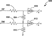
Fig. 6 is the synoptic diagram of a/D converter circuit 600 according to an embodiment of the invention.A/D converter circuit 600 is suitable for the a/D converter circuit 506 as graphic extension in Fig. 5.A/D converter circuit 600 comprises resistor 602 and 604, and the analog-digital converter (ADC) that the aanalogvoltage on the data line DP is converted to the numeral output of n position.Similarly, resistor 608 and 610 and ADC 612 aanalogvoltage on the data line DM is converted to the numeral output of n position.
In the alternative of the a/D converter circuit 506 of graphic extension in about Fig. 5, by switch or multiplexer and the only use of the a/D converter circuit 600 of a part, data line DP and DM can share the change-over circuit system.For example, switch or multiplexer can couple one of data line DM or DP and resistor 602 selectively, so the output of ADC 606 can be on the data line DM or data line DP on digital voltage, thereby do not need resistor 608 and 610 and ADC 612.
Fig. 7 is the block scheme of power-supply management system 700 according to an embodiment of the invention.Power-supply management system 700 is described power supervisor according to an embodiment of the invention, such as the typical operation of power supervisor 512.Power-supply management system 700 is represented the part of electronic equipment.
Power-supply management system 700 comprises a power supervisor 702.Power supervisor 702 is from available power detector, and for example available power detector 510 receives available power level (available power level:APL).Power supervisor 702 is according to the work of available power level control electronic circuit system.As shown in Figure 7, power-supply management system 700 can couple with battery 704 and battery monitor 706.Battery monitor 706 can monitoring battery electric weight (battery charge level:BCL), and battery electric quantity is offered power supervisor 702.Thereby power supervisor 702 can also be controlled the work of electronic circuit system according to battery electric quantity.In other words, power supervisor 702 can be according to available horsepower level and/or battery electric quantity, the energy consumption of managing electronic equipment.
The electric energy that power supply is supplied with electronic equipment can be coupled to battery 704 by battery charger 708.Battery charger 708 can be by power supervisor 702 control, so that the electric energy that can obtain from power supply or can be used for perhaps can preventing to be used to battery 704 chargings to battery 704 chargings.Power-supply management system 700 also comprises other power consumption Circuits System 710 relevant with electronic equipment.Described other power consumption Circuits System 710 can greatly change along with realization.But, some or whole power consumption Circuits System 710 can be by power supervisor 702 controls.For example, power supervisor 702 can limit the use of some Circuits System, can make Circuits System according to different sequence startings, can change the use of Circuits System etc.When doing like this, power supervisor 702 not only can utilize available power level, and can use battery electric quantity.As shown in Figure 7, from battery P
BATElectric energy with from power supply P
INThe electric energy combination, thereby produce equipment electric energy P
OUTEquipment electric energy P
OUTAt least be provided for power supervisor 702, battery monitor 706 and other power consumption Circuits System 710.Thereby even energy consumption is managed by power supervisor 702, the electric energy of drawing from electronic equipment also can surpass the electric energy of being imported electronic equipment by power amplifier, that is, and and electric energy P
INIf, can be from battery P
BATIt is poor to obtain electric energy.
Fig. 8 is the process flow diagram of available power process 800 according to an embodiment of the invention.Available power process 800 is by electronic equipment, carries out such as the electronic equipment of graphic extension among the electronic equipment 112 of graphic extension among Figure 1A and the 1B or Fig. 5.
In case determination step 802 determines to have detected external bus,, read voltage level from the bus data line of external bus just in step 804.For example, can be from data line DP and DM, such as the voltage level that reads of graphic extension among Fig. 5.Subsequently, at determination step 806, determine whether main equipment is power supply.Detected external bus can comprise power supply and computing machine from various equipment (for example main equipment).In one embodiment, the type of the notice of the voltage level available signal on bus data line main equipment.For example, the present invention is particularly suitable for being provided as the main equipment use of power supply.More specifically, the notice of the voltage level available signal on bus data line main equipment is a power supply.In one implementation, on the bus data line be the existence of the voltage level available signal notice power supply of " height ".
In a word, when determination step 806 determines that main equipment is not power supply, can carry out other standard so and handle 808.For example, if main equipment is a computing machine, other standard processing 808 can relate to the operation that promotes the exchange of data between computing machine and the electronic equipment so.
On the other hand, when determination step 806 determines that main equipment is power supply, determine the available power level of power supply in step 810.In one embodiment, by the voltage level on the further inspection bus data line, can determine the available power level of power supply.That is, the notice of the voltage level available signal on the bus data line can be from the power level of power supply acquisition.For example, as above described with reference to figure 4, the voltage level on the bus data line can be classified into a plurality of " height " voltage level H
1, H
2, H
3..., H
n, described a plurality of " height " voltage level H
1, H
2, H
3..., H
nBe considered to correspond respectively to the different available power level that provides by power supply, promptly 0.5,1,3 ..., 8 watts.
After step 810 has been determined available power level, in step 812, can be according to the utilization of power of the available power level managing electronic equipment of determining.That is, in the work of electronic equipment, but utilization of power Be Controlled or management, consequently operation or function can change along with the available power level of determining.
Next after square frame 808 and 812, determination step 814 determines whether external bus is disconnected.When determination step 814 determines that external bus is not disconnected, handle and return repetition determination step 812, so that can continue the utilization of power of managing electronic equipment.On the other hand, when determination step 814 determines that external bus has been disconnected, handle and return repetition determination step 802 and follow-up each square frame, so that when being connected to electronic equipment after the external bus, electronic equipment can be carried out available power process 800 once more.
Needing a kind of operation of high electric energy especially is bootup process, and bootup process relates to the initial start of electronic equipment.In general, the electronic equipment of carrying out bootup process can comprise a disk drive, and described disk drive is preserved the program code that is used for or guides the operating system of electronic equipment.
Fig. 9 is the process flow diagram of bootup process 900 according to an embodiment of the invention.Electronic equipment can be carried out bootup process 900, carries out work to start electronic equipment.
On the other hand, when determination step 902 is judged definite available power level more than or equal to minimum boot power level, can directly carry out homing sequence in step 901.Therefore, if the available power level of determining of being supplied with by power supply is considered to surpass the required minimum boot power level of proper operation electronic equipment in homing sequence, bootup process 900 allows to carry out immediately homing sequence so.But, be not equal to or do not surpass under the situation of minimum boot power level in the available power level of determining of supplying with by power supply, need draw extra electric energy from the battery of electronic equipment.Thereby determination step 906 guarantees that can be before step 910 is carried out homing sequence, battery has minimum amount of power at least.After step 910 was carried out homing sequence, bootup process 900 was finished and is finished.
Electronic equipment described herein can be the media player that can play (comprising demonstration) media item.Media item can and audio items (for example audio file or song), video (for example film) or image (for example photo) are relevant.
Figure 10 is the block scheme that is suitable for for the media player 1000 of the present invention's usefulness.Media player 1000 can comprise the electronic equipment 112 among Figure 1A and the 1B or the Circuits System of the electronic equipment 500 among Fig. 5, and/or can carry out the operations with reference to figure 8 and 9 explanations.
In one embodiment, media player 1000 is used for a plurality of media items (for example song) are kept at file system 1004.When the user wanted to make the specific media item of media renderer plays, the tabulation of available media items purpose was displayed on the display 1010.Subsequently, by utilizing user input apparatus 1008, the user can select one of available media items.When receiving that the certain media items purpose is selected, processor 1002 offers encoder/decoder (CODEC) 1012 to certain media items purpose media data (for example audio file).Codec 1012 produces the analog output signal of giving loudspeaker 1014 subsequently.Loudspeaker 1014 can be the boombox of media player 1000 or the external speaker of media player 1000.For example, head phone that is connected with media player 1000 or earplug can be counted as external speaker.
Various aspects of the present invention, embodiment, realization or feature can independently be used or combination in any ground uses.
The combination of the most handy hardware of the present invention, software or hardware and software realizes.Software also can be embodied in the computer-readable code on the computer-readable medium.Computer-readable medium is can be by the arbitrary data memory storage of the data of computer system reads after can preserving.The example of computer-readable medium comprises ROM (read-only memory), random access memory, CD-ROM, DVD, tape, optical data storage device and carrier wave.Computer-readable medium also can be distributed in the computer system of network connection, so that preserves and computer readable code executed according to distribution mode.
Advantage of the present invention is numerous.Different aspects, embodiment or realization can produce one or more following advantages.An advantage of the present invention is that portable media device can be easily and determine apace whether power supply is connected to its outside port, if can determine can draw how many electric energy from power supply by outside port so.Another advantage of the present invention is that the utilization of power of portable media device decided by available electrical energy, so that stable operation and reliable.
According to written description, many feature and advantage of the present invention are significantly, thereby additional claim intention covers all this feature and advantage of the present invention.In addition, owing to those skilled in the art is easy to expect numerous modifications and variations, so the present invention should not be limited to illustrational precise structure and operation here.Thereby modification and equivalent that all are suitable fall within the scope of the present invention.
Claims (34)
1, a kind of electronic equipment comprises:
With the bus interface that Bussing connector couples, Bussing connector provides power transmission line, ground wire and a plurality of data line to described bus interface;
The available power detector that is connected with described bus interface in the operation, wherein, when power supply was connected with described bus interface in operation by Bussing connector, described available power detector read voltage level on described a plurality of data line with the available power level of detection from power transmission line;
The power consumption Circuits System; With
The power supervisor that is connected with described power consumption Circuits System with described available power detector in the operation, wherein, described power supervisor is managed the utilization of power of the described power consumption Circuits System of at least a portion according to available power level.
2, according to the described electronic equipment of claim 1, wherein said electronic equipment also comprises battery.
3, according to the described electronic equipment of claim 2, wherein said electronic equipment also comprises:
The battery monitor that couples with described battery in the operation, described battery monitor monitors the electric weight of described battery.
4, according to the described electronic equipment of claim 3, wherein said power supervisor is managed the utilization of power of the described power consumption Circuits System of at least a portion according to available power level and electric weight.
5, according to the described electronic equipment of claim 3, wherein the described power consumption Circuits System of at least a portion comprises disk drive at least.
6, according to the described electronic equipment of claim 5, wherein said power supervisor is controlled described electronic equipment and when or how to be used disk drive to start.
7, according to the described electronic equipment of claim 1, wherein said power consumption Circuits System comprises disk drive at least.
8, according to the described electronic equipment of claim 7, wherein said power supervisor is controlled described electronic equipment and when or how to be used disk drive to start.
9, according to the described electronic equipment of claim 8, wherein said electronic equipment also comprises battery.
10, according to the described electronic equipment of claim 9, wherein said electronic equipment also comprises:
The battery monitor that couples with described battery in the operation, described battery monitor monitors the electric weight of described battery.
11, according to the described electronic equipment of claim 10, wherein said power supervisor is managed the utilization of power of the disk drive at least of described power consumption Circuits System according to available power level and electric weight.
12, according to the described electronic equipment of claim 1, wherein said electronic equipment is a portable electronic device.
13, according to the described electronic equipment of claim 12, wherein said power consumption Circuits System comprises disk drive at least, and described disk drive is preserved can be by a plurality of media items of portable electronic device broadcast.
14, according to the described electronic equipment of claim 12, wherein power supply is power supply adaptor or electric battery.
15, a kind of management has the method for utilization of power of the electronic equipment of Bussing connector, and described method comprises:
Detect being connected of Bussing connector of external bus and electronic equipment, described external bus has power transmission line and multiple bus data line at least;
When described detection motion detection arrives the connection of external bus, read the voltage level on the described multiple bus data line;
According to described voltage level, determining provides whether the main equipment of external bus is power supply adaptor;
When described definite action determines that main equipment is power supply adaptor,, determine the available power level of power supply adaptor according to described voltage level; With
According to the available power level of power supply adaptor, the utilization of power of managing electronic equipment.
16, in accordance with the method for claim 15, wherein Bussing connector is a USB connector.
17, in accordance with the method for claim 15, wherein Bussing connector is the FIREWIRE connector.
18, in accordance with the method for claim 15, wherein said electronic equipment comprises that processor and at least one preserve the disk drive of computer program code, and described processor can be according to the computer program code work of preserving,
When or how wherein said management activities management processor uses disk drive to start.
19, in accordance with the method for claim 18, wherein said electronic equipment is a portable electronic device.
20, in accordance with the method for claim 19,
Wherein Bussing connector is a USB connector, and
Wherein when described detection motion detection arrived the connection of external bus, the voltage level that is used to the available power level of definite power supply adaptor was the minimum levels voltage of " height " or " low " greater than the voltage that is used on the specified data line all.
21, in accordance with the method for claim 20, wherein, the voltage level of available power level that is used to determine power supply adaptor is in the scope of 2.0-3.3 volt.
22, a kind of management has the method for the utilization of power of the electronic equipment that bus connects, and described method comprises:
Detect being connected of Bussing connector of external bus and electronic equipment, described external bus has power transmission line and multiple bus data line at least;
When described detection motion detection arrives the connection of external bus, read the voltage level on the described multiple bus data line;
According to described voltage level, determining provides whether the main equipment of external bus is electric battery;
When described definite action determines that main equipment is electric battery,, determine the available electrical energy capacity of electric battery according to described voltage level; With
According to the available electrical energy capacity of electric battery, the utilization of power of managing electronic equipment.
23, a kind ofly determine that described external bus has power transmission line and multiple bus data line at least from the method for the power availability of the power supply adaptor that couples by external bus and electronic equipment, described method comprises:
Read the voltage level that power supply adaptor is responded on described multiple bus data line; With
According to described voltage level, determine the available power level of power supply adaptor.
24, in accordance with the method for claim 23, wherein said method also comprises:
Afterwards according to the available power level of power supply adaptor, the utilization of power of managing electronic equipment.
25, in accordance with the method for claim 24, wherein electronic equipment comprises that processor and at least one preserve the disk drive of computer program code, and described processor can be according to the computer program code work of preserving,
When or how wherein said management activities management processor uses disk drive to start.
26, in accordance with the method for claim 25, wherein said electronic equipment is a portable electronic device.
27, in accordance with the method for claim 23, wherein said electronic equipment is a portable electronic device.
28, a kind ofly determine that described external bus has power transmission line and multiple bus data line at least from the method for the power availability of the electric battery that couples by external bus and electronic equipment, described method comprises:
Read the voltage level that electric battery is responded on described multiple bus data line; With
According to described voltage level, determine the available power level of electric battery.
29, in accordance with the method for claim 28, wherein said method also comprises:
Afterwards according to the available power level of electric battery, the utilization of power of managing electronic equipment.
30, in accordance with the method for claim 29, wherein electronic equipment comprises that processor and at least one preserve the disk drive of computer program code, and described processor can be according to the computer program code work of preserving,
When or how wherein said management activities management processor uses disk drive to start.
31, in accordance with the method for claim 30, wherein said electronic equipment is a portable electronic device.
32, the method for the external unit that couples of the aerial lug of a kind of identification and electronic equipment, described method comprises:
Detect being connected of Bussing connector of external bus and electronic equipment, described external bus is associated with the same main equipment that is connected with this external bus, and described external bus has power transmission line and multiple bus data line at least;
After described detection motion detection arrives the connection of external bus, read the voltage level on the described multiple bus data line; With
According to voltage level, the identification main equipment is power supply adaptor or electric battery.
33, according to the described method of claim 32, wherein electronic equipment is a portable electronic device.
34, according to the described method of claim 33, wherein said method also comprises:
According to voltage level, determine the available power level of power supply adaptor or electric battery.
Applications Claiming Priority (6)
| Application Number | Priority Date | Filing Date | Title |
|---|---|---|---|
| US58895904P | 2004-07-18 | 2004-07-18 | |
| US60/588,959 | 2004-07-18 | ||
| US60895904P | 2004-10-08 | 2004-10-08 | |
| US60/608,959 | 2004-10-08 | ||
| US11/031,288 US7581119B2 (en) | 2004-07-18 | 2005-01-07 | Method and system for discovering a power source on a peripheral bus |
| US11/031,288 | 2005-01-07 |
Related Child Applications (1)
| Application Number | Title | Priority Date | Filing Date |
|---|---|---|---|
| CN2009102087422A Division CN101694595B (en) | 2004-07-18 | 2005-07-12 | Method and system for discovering a power source on a peripheral bus |
Publications (2)
| Publication Number | Publication Date |
|---|---|
| CN1989477A CN1989477A (en) | 2007-06-27 |
| CN100573417C true CN100573417C (en) | 2009-12-23 |
Family
ID=35004185
Family Applications (2)
| Application Number | Title | Priority Date | Filing Date |
|---|---|---|---|
| CN2009102087422A Active CN101694595B (en) | 2004-07-18 | 2005-07-12 | Method and system for discovering a power source on a peripheral bus |
| CNB2005800241789A Active CN100573417C (en) | 2004-07-18 | 2005-07-12 | Find the method and system of the power supply on the external bus |
Family Applications Before (1)
| Application Number | Title | Priority Date | Filing Date |
|---|---|---|---|
| CN2009102087422A Active CN101694595B (en) | 2004-07-18 | 2005-07-12 | Method and system for discovering a power source on a peripheral bus |
Country Status (7)
| Country | Link |
|---|---|
| US (3) | US7581119B2 (en) |
| EP (2) | EP2209059A1 (en) |
| JP (2) | JP4664362B2 (en) |
| KR (2) | KR100997309B1 (en) |
| CN (2) | CN101694595B (en) |
| HK (1) | HK1102339A1 (en) |
| WO (1) | WO2006019850A2 (en) |
Cited By (3)
| Publication number | Priority date | Publication date | Assignee | Title |
|---|---|---|---|---|
| CN103314339A (en) * | 2011-01-17 | 2013-09-18 | 高通股份有限公司 | Booting a mobile electronic device with a low battery based on a dynamic boot threshold |
| CN106462208A (en) * | 2014-06-27 | 2017-02-22 | 英特尔公司 | Usb power delivery controller sharing |
| CN108123520A (en) * | 2012-10-29 | 2018-06-05 | 高通股份有限公司 | High voltage special charging port |
Families Citing this family (79)
| Publication number | Priority date | Publication date | Assignee | Title |
|---|---|---|---|---|
| US9153960B2 (en) | 2004-01-15 | 2015-10-06 | Comarco Wireless Technologies, Inc. | Power supply equipment utilizing interchangeable tips to provide power and a data signal to electronic devices |
| US7868486B2 (en) | 2004-01-15 | 2011-01-11 | Comarco Wireless Technologies, Inc | Power supply having source determination circuitry utilized to disable battery charging circuitry in powered device |
| US7581119B2 (en) | 2004-07-18 | 2009-08-25 | Apple Inc. | Method and system for discovering a power source on a peripheral bus |
| US20060082934A1 (en) * | 2004-10-15 | 2006-04-20 | Dell Products L.P. | Power adapter featuring multiple power outputs |
| US7885622B2 (en) * | 2004-10-27 | 2011-02-08 | Chestnut Hill Sound Inc. | Entertainment system with bandless tuning |
| US8090309B2 (en) * | 2004-10-27 | 2012-01-03 | Chestnut Hill Sound, Inc. | Entertainment system with unified content selection |
| US20190278560A1 (en) | 2004-10-27 | 2019-09-12 | Chestnut Hill Sound, Inc. | Media appliance with auxiliary source module docking and fail-safe alarm modes |
| JP2007068333A (en) * | 2005-08-31 | 2007-03-15 | Sony Corp | Power supply-dedicated device, terminal, power supply system, and power supply method |
| US20070079153A1 (en) * | 2005-10-05 | 2007-04-05 | Dell Products L.P. | Information handling system, current and voltage mode power adapter, and method of operation |
| US7653823B2 (en) * | 2006-03-20 | 2010-01-26 | Lenovo (Singapore) Pte. Ltd. | Method and apparatus for informing computer of power environment |
| US20100201308A1 (en) * | 2006-06-29 | 2010-08-12 | Nokia Corporation | Device and method for battery charging |
| DE102006036770A1 (en) * | 2006-08-07 | 2008-02-14 | Siemens Ag | Method for commissioning at least one field device |
| US20080053770A1 (en) * | 2006-08-31 | 2008-03-06 | Timothy Tynyk | Travel case for a portable electronic device |
| US7728558B2 (en) * | 2007-01-05 | 2010-06-01 | Apple Inc. | Systems and methods for selectively changing current limit of a battery controller |
| FR2913508B1 (en) * | 2007-03-09 | 2009-07-24 | Archos Sa | DEVICE FOR FEEDING A PORTABLE ELECTRONIC DEVICE BY COMBINING ENTRY / EXIT PORTS OF AT LEAST ONE OTHER ELECTRONIC EQUIPMENT, SYSTEM, METHOD AND APPLICATION THEREOF. |
| PL2130108T3 (en) | 2007-03-29 | 2018-07-31 | Nokia Technologies Oy | Connection to a usb device |
| US7671559B2 (en) | 2007-07-31 | 2010-03-02 | Apple Inc. | Battery charging system and mobile and accessory devices |
| KR101339822B1 (en) * | 2007-10-15 | 2013-12-11 | 삼성전자주식회사 | Method for controlling device based on a kind of peripheral device and potable device using the same |
| US20090267570A1 (en) * | 2008-04-28 | 2009-10-29 | Nokia Corporation | Apparatus for providing boot-up capability signals and associated methods |
| TWI459190B (en) * | 2009-07-22 | 2014-11-01 | Htc Corp | Power supply device, portable electronic apparatus and related method for determining types of a power supply device |
| TWI398759B (en) | 2009-07-22 | 2013-06-11 | Htc Corp | Power supply device, portable electronic apparatus and related method for determining types of a power supply device |
| CN101989751B (en) * | 2009-07-30 | 2014-01-15 | 宏达国际电子股份有限公司 | Power supply device, portable electronic device and related judgment method |
| DE102009036586B4 (en) * | 2009-08-07 | 2014-02-20 | Fm Marketing Gmbh | Wireless remote control |
| US8626932B2 (en) * | 2009-09-01 | 2014-01-07 | Apple Inc. | Device-dependent selection between modes for asymmetric serial protocols |
| US9130400B2 (en) * | 2009-09-24 | 2015-09-08 | Apple Inc. | Multiport power converter with load detection capabilities |
| KR101667707B1 (en) * | 2009-10-22 | 2016-10-19 | 엘지전자 주식회사 | Mobile terminal and usb dedicated charger determinating method thereof |
| US8358100B2 (en) * | 2009-11-03 | 2013-01-22 | Maxim Integrated Products, Inc. | USB dedicated charger identification circuit |
| WO2011080915A1 (en) | 2009-12-28 | 2011-07-07 | パナソニック株式会社 | Electronic apparatus, method for controlling electronic apparatus, computer program, and recording medium |
| US8069356B2 (en) | 2010-01-06 | 2011-11-29 | Apple Inc. | Accessory power management |
| US8350522B2 (en) | 2010-03-10 | 2013-01-08 | Apple Inc. | External power source voltage drop compensation for portable devices |
| US8717044B2 (en) * | 2010-04-23 | 2014-05-06 | Apple Inc. | Charging systems with direct charging port support and extended capabilities |
| EP2383860B1 (en) * | 2010-04-29 | 2019-11-27 | Giga-Byte Technology Co., Ltd. | Rapid charging apparatus |
| EP2383630B1 (en) * | 2010-04-30 | 2018-09-26 | BlackBerry Limited | Configuring cable lines to provide data and power |
| US9292066B2 (en) | 2010-04-30 | 2016-03-22 | Blackberry Limited | Configuring cable lines to provide data and power |
| US9336170B2 (en) * | 2010-05-11 | 2016-05-10 | Mediatek Inc. | Universal serial bus device and charging and enumeration method |
| KR101771452B1 (en) | 2010-08-23 | 2017-08-25 | 엘지전자 주식회사 | Mobile terminal and usb dedicated charger determinating method thereof |
| US8513955B2 (en) * | 2010-09-28 | 2013-08-20 | Tyco Electronics Corporation | SSL budgeting and coding system for lighting assembly |
| KR101218359B1 (en) * | 2011-03-02 | 2013-01-03 | 삼성테크윈 주식회사 | Electric device comprising a movable battery-container |
| US8560031B2 (en) | 2011-03-16 | 2013-10-15 | David B. Barnett | Extending socket for portable media player |
| US8762746B1 (en) * | 2011-03-22 | 2014-06-24 | Amazon Technologies, Inc. | Power management in electronic devices |
| FR2974197B1 (en) * | 2011-04-14 | 2013-05-17 | Hongbing Zhang | POWER SUPPLY DEVICE FOR COMPUTER |
| CN102301305B (en) * | 2011-06-09 | 2015-12-16 | 华为终端有限公司 | A kind of method and system that USB device is powered |
| CN102265552A (en) * | 2011-06-24 | 2011-11-30 | 华为终端有限公司 | A power supplying method of a wireless net connection terminal and the wireless net connection terminal |
| JP5367030B2 (en) * | 2011-08-10 | 2013-12-11 | シャープ株式会社 | Electronic equipment and electronic equipment system |
| US8689022B2 (en) | 2011-08-30 | 2014-04-01 | Qualcomm Incorporated | Methods of and apparatus for controlling power drawn by an appliance through a USB port |
| WO2013058729A1 (en) * | 2011-10-17 | 2013-04-25 | Intel Corporation | Host controlled io power management |
| JP5773920B2 (en) * | 2012-03-19 | 2015-09-02 | ルネサスエレクトロニクス株式会社 | Charger |
| CN102769320A (en) * | 2012-07-31 | 2012-11-07 | 徐州华夏电子有限公司 | Car charging device for iphone |
| JP2014056287A (en) | 2012-09-11 | 2014-03-27 | Ricoh Co Ltd | Electronic apparatus and method of determining power source device by electronic apparatus |
| US8760123B2 (en) * | 2012-10-29 | 2014-06-24 | Qualcomm Incorporated | High voltage dedicated charging port |
| KR200472137Y1 (en) * | 2012-11-09 | 2014-04-10 | 최규택 | Universal gender for charging mobile phone |
| TWI460964B (en) * | 2012-12-07 | 2014-11-11 | Pegatron Corp | Adapter and electronic device and method for detecting power of the adapter |
| JP6288913B2 (en) * | 2012-12-28 | 2018-03-07 | キヤノン株式会社 | Electronic device and program |
| US10162399B2 (en) | 2013-03-06 | 2018-12-25 | Hewlett-Packard Development Company, L.P. | Power supply voltage and load consumption control |
| EP2965416B1 (en) * | 2013-03-06 | 2018-12-26 | Hewlett-Packard Development Company, L.P. | Power supply voltage and load consumption control |
| US9312707B2 (en) * | 2013-05-10 | 2016-04-12 | S P Technologies LLC | Portable compact multiple-outlet power supply with circuit for supplying device-specific charging profiles to mobile telephones |
| CN104810868B (en) * | 2014-01-24 | 2017-05-10 | 华硕电脑股份有限公司 | Charging system and charging method thereof |
| JP5922165B2 (en) * | 2014-02-21 | 2016-05-24 | ホシデン株式会社 | Charging holder |
| US9553341B2 (en) | 2014-02-25 | 2017-01-24 | Motorola Solutions, Inc. | Method and apparatus for controlling access to a logic circuit in a battery by multiple components connected to the battery |
| US10355505B2 (en) * | 2014-03-10 | 2019-07-16 | Dell Products L.P. | Method for adapter over-current-protection (OCP) protection and user warning |
| CN105278650B (en) * | 2014-05-28 | 2018-10-12 | 精工爱普生株式会社 | Electronic equipment |
| US9588563B2 (en) | 2014-05-30 | 2017-03-07 | Apple Inc. | Protocol for managing a controllable power adapter accessory |
| US9634502B2 (en) * | 2014-08-20 | 2017-04-25 | Qualcomm Incorporated | Fast battery charging through digital feedback |
| TWI547952B (en) * | 2014-10-07 | 2016-09-01 | 新唐科技股份有限公司 | Controlling device, controlled device, and operating method |
| CN105630124A (en) * | 2014-12-01 | 2016-06-01 | 鸿富锦精密工业(武汉)有限公司 | Electronic equipment interface switching device |
| US10234919B2 (en) | 2015-09-21 | 2019-03-19 | Microsoft Technology Licensing, Llc | Accessory-based power distribution |
| US9690346B1 (en) * | 2015-10-30 | 2017-06-27 | Seagate Technology Llc | Load sharing across multiple voltage supplies |
| AT517928A2 (en) * | 2015-11-06 | 2017-05-15 | Keba Ag | Control system for electrically controlled systems |
| US9800703B2 (en) | 2015-11-23 | 2017-10-24 | TecTide Group, LLC | Handling apparatus for portable electronic devices |
| US10666070B2 (en) | 2016-01-07 | 2020-05-26 | Fairchild Semiconductor Corporation | Battery charge termination voltage reduction |
| US10256653B2 (en) * | 2016-04-12 | 2019-04-09 | Samsung Electronics Co., Ltd. | Electronic device and method for charging battery |
| US10054259B2 (en) | 2016-08-17 | 2018-08-21 | Popsockets Llc | Expanding socket accessory for mobile electronic device |
| KR102597036B1 (en) | 2016-10-11 | 2023-11-02 | 삼성전자주식회사 | electronic device having a dual-display and operating method thereof |
| US10459502B2 (en) | 2016-10-21 | 2019-10-29 | Seagate Technology Llc | Adaptive charge leveling in a data storage device |
| EP3367210A1 (en) * | 2017-02-24 | 2018-08-29 | Thomson Licensing | Method for operating a device and corresponding device, system, computer readable program product and computer readable storage medium |
| US10447052B2 (en) | 2017-03-23 | 2019-10-15 | Intel Corporation | Apparatus, method, and system for dynamically controlling current and/or voltage profiles |
| CN110165725B (en) * | 2019-04-26 | 2021-05-11 | 华为技术有限公司 | Wireless charging method, receiver, terminal equipment and charger |
| CN110286731A (en) * | 2019-06-30 | 2019-09-27 | 联想(北京)有限公司 | A kind of information processing method and electronic equipment |
| WO2024010519A1 (en) * | 2022-07-08 | 2024-01-11 | Razer (Asia-Pacific) Pte. Ltd. | A bus powered device |
Family Cites Families (89)
| Publication number | Priority date | Publication date | Assignee | Title |
|---|---|---|---|---|
| US4257098A (en) * | 1978-10-30 | 1981-03-17 | Phillips Petroleum Company | Computer to recording medium interface |
| US6075340A (en) * | 1985-11-12 | 2000-06-13 | Intermec Ip Corp. | Battery pack having memory |
| US4673861A (en) * | 1986-04-03 | 1987-06-16 | General Electric Company | Battery charger/remote control for portable radio devices |
| US4965738A (en) * | 1988-05-03 | 1990-10-23 | Anton/Bauer, Inc. | Intelligent battery system |
| US5150031A (en) * | 1988-09-30 | 1992-09-22 | Motorola, Inc. | Battery charging system |
| US5103156A (en) * | 1990-12-21 | 1992-04-07 | Dallas Semiconductor Corporation | Battery manager chip with differential temperature sensing |
| US5514945A (en) * | 1990-12-21 | 1996-05-07 | Dallas Semiconductor Corporation | Battery charging systems |
| AU3816293A (en) * | 1992-03-18 | 1993-10-21 | Grid Systems Corporation | A power supply and battery charging system |
| US5402055A (en) * | 1992-09-30 | 1995-03-28 | Compaq Computer Corporation | AC adapter including differential comparator for tracking battery voltage during trickle charge |
| US5592069A (en) * | 1992-10-07 | 1997-01-07 | Dallas Semiconductor Corporation | Battery charger |
| US5483656A (en) * | 1993-01-14 | 1996-01-09 | Apple Computer, Inc. | System for managing power consumption of devices coupled to a common bus |
| US6321750B1 (en) * | 1993-05-03 | 2001-11-27 | Patrick D. Kelly | Condom lubricants with zinc salts as anti-viral additives |
| GB2286732B (en) * | 1993-09-15 | 1998-05-06 | Ericsson Ge Mobile Communicat | Power systems for plug-in modules |
| US5471128A (en) * | 1993-11-26 | 1995-11-28 | Motorola, Inc. | Battery and method for charging/discharging the battery |
| US5498950A (en) * | 1994-04-29 | 1996-03-12 | Delco Electronics Corp. | Battery monitoring, charging and balancing apparatus |
| US5602455A (en) * | 1994-11-04 | 1997-02-11 | Hewlett-Packard Company | Portable battery charger with integrally attached output cable |
| JPH08152945A (en) | 1994-11-28 | 1996-06-11 | Nec Corp | Power consumption managing device |
| WO1996019764A1 (en) * | 1994-12-22 | 1996-06-27 | Intel Corporation | Power budgeting with device specific characterization of power consumption |
| US5870615A (en) * | 1995-01-09 | 1999-02-09 | Intel Corporation | Automatic cellular phone battery charging by mobile personal computer using configuration write data and storage element for charging in accordance to battery charging parameter |
| US5504413A (en) * | 1995-07-25 | 1996-04-02 | Motorola, Inc. | Battery charging system with power management of plural peripheral devices |
| US5648712A (en) * | 1995-08-29 | 1997-07-15 | Asian Micro Sources, Inc. | Universally interchangeable and modular power supply with integrated battery charger |
| US5754027A (en) * | 1996-07-08 | 1998-05-19 | Motorola, Inc. | Battery pack and associated charging system |
| AU3803097A (en) * | 1996-07-17 | 1998-02-09 | Duracell Inc. | Battery operating system |
| WO1998012846A1 (en) * | 1996-09-18 | 1998-03-26 | Delorme Publishing Company, Inc. | Gps power/data cable system |
| US5783926A (en) * | 1996-11-05 | 1998-07-21 | Ericsson, Inc. | Apparatus for identifying accessories connected to radiotelephone equipment |
| US5914605A (en) * | 1997-01-13 | 1999-06-22 | Midtronics, Inc. | Electronic battery tester |
| KR100211801B1 (en) * | 1997-03-12 | 1999-08-02 | 윤종용 | Power control method and apparatus |
| US6459175B1 (en) | 1997-11-17 | 2002-10-01 | Patrick H. Potega | Universal power supply |
| US6025695A (en) * | 1997-07-09 | 2000-02-15 | Friel; Daniel D. | Battery operating system |
| US5859522A (en) * | 1997-07-16 | 1999-01-12 | Motorola, Inc. | Accessory identification apparatus and method |
| US6211581B1 (en) * | 1997-11-28 | 2001-04-03 | Harvard M. Farrant | Power bar with remote control |
| JP4124873B2 (en) * | 1997-12-17 | 2008-07-23 | キヤノン株式会社 | Power control system |
| US6169387B1 (en) * | 1997-12-22 | 2001-01-02 | Lifecor, Inc. | Battery management apparatus for portable electronic devices |
| US6152778A (en) * | 1998-02-26 | 2000-11-28 | Hewlett-Packard Company | Electronic connector adapter with power input |
| US5932989A (en) * | 1998-05-04 | 1999-08-03 | Motorola, Inc. | Method for an electronic device to detect the presence of a battery charger |
| JP2000020175A (en) * | 1998-06-26 | 2000-01-21 | Toshiba Corp | Electronic appliance |
| US6357011B2 (en) * | 1998-07-15 | 2002-03-12 | Gateway, Inc. | Bus-powered computer peripheral with supplement battery power to overcome bus-power limit |
| US6178514B1 (en) * | 1998-07-31 | 2001-01-23 | Bradley C. Wood | Method and apparatus for connecting a device to a bus carrying power and a signal |
| TW399796U (en) * | 1998-09-28 | 2000-07-21 | Delta Electronics Inc | Switching plug fastening structure of general type power receptacle |
| SE515626C2 (en) * | 1998-12-22 | 2001-09-10 | Ericsson Telefon Ab L M | Device for exchanging digital information between electrical circuits through current and voltage sequence and battery with such device |
| WO2000039907A1 (en) | 1998-12-31 | 2000-07-06 | Potega Patrick H | Systems for configuring and delivering power |
| US6204637B1 (en) * | 1999-03-16 | 2001-03-20 | International Business Machines Corporation | Method and system for remotely supplying power through an automated power adapter to a data processing system |
| US6211649B1 (en) * | 1999-03-25 | 2001-04-03 | Sourcenext Corporation | USB cable and method for charging battery of external apparatus by using USB cable |
| DE19914004B4 (en) * | 1999-03-29 | 2005-04-14 | Robert Bosch Gmbh | Identifiable electrical component with methods of identification and evaluation |
| US6326767B1 (en) * | 1999-03-30 | 2001-12-04 | Shoot The Moon Products Ii, Llc | Rechargeable battery pack charging system with redundant safety systems |
| US6353894B1 (en) * | 1999-04-08 | 2002-03-05 | Mitsumi Electric Co., Ltd. | Power management system |
| US6271605B1 (en) * | 1999-05-04 | 2001-08-07 | Research In Motion Limited | Battery disconnect system |
| JP2001069165A (en) | 1999-08-25 | 2001-03-16 | Matsushita Electric Works Ltd | Usb hub |
| JP4580132B2 (en) * | 1999-09-01 | 2010-11-10 | 富士通フロンテック株式会社 | Battery management circuit |
| US6633932B1 (en) | 1999-09-14 | 2003-10-14 | Texas Instruments Incorporated | Method and apparatus for using a universal serial bus to provide power to a portable electronic device |
| US6535983B1 (en) | 1999-11-08 | 2003-03-18 | 3Com Corporation | System and method for signaling and detecting request for power over ethernet |
| US6184655B1 (en) * | 1999-12-10 | 2001-02-06 | Stryker Corporation | Battery charging system with internal power manager |
| US6316916B2 (en) * | 1999-12-17 | 2001-11-13 | Motorola, Inc. | Method and mechanism to prevent corruption of data |
| US6130518A (en) * | 1999-12-22 | 2000-10-10 | Motorola, Inc. | Method and apparatus for charging a battery |
| JP3819658B2 (en) * | 1999-12-27 | 2006-09-13 | 三洋電機株式会社 | Portable electronic devices with a common serial bus connector |
| JP2001184147A (en) * | 1999-12-27 | 2001-07-06 | Sanyo Electric Co Ltd | Portable electronic equipment |
| JP4298878B2 (en) | 2000-02-17 | 2009-07-22 | インターナショナル・ビジネス・マシーンズ・コーポレーション | Display method of power consumption information and electronic device |
| DE20004691U1 (en) * | 2000-03-14 | 2000-06-29 | Yang Wen Chin | Charging device with USB interface for a GSM telephone battery |
| US6283789B1 (en) * | 2000-03-16 | 2001-09-04 | Shui Chuan Tsai | Data and power transmitting cable system |
| JP3690727B2 (en) | 2000-05-26 | 2005-08-31 | 株式会社平和 | Pachinko gaming machine with ball stop prevention structure |
| JP2001344047A (en) * | 2000-05-30 | 2001-12-14 | Toshiba Corp | Electronic equipment and power supply control method for electronic equipment |
| DE60136820D1 (en) * | 2000-07-11 | 2009-01-15 | Thomson Licensing | POWER ADAPTER FOR A MODULAR POWER SUPPLY NETWORK |
| JP2002041441A (en) * | 2000-07-27 | 2002-02-08 | Canon Inc | Communication equipment connection device and peripheral device having connection function |
| US20040225804A1 (en) * | 2000-12-05 | 2004-11-11 | Intel Corporation | Power supply with bus hub |
| JP2002204276A (en) * | 2000-12-28 | 2002-07-19 | Canon Inc | Data communication system, method for controlling power supply and power supply receiver |
| CA2374344C (en) * | 2001-03-01 | 2006-02-21 | Research In Motion Limited | Multifunctional charger system and method |
| JP3687740B2 (en) * | 2001-04-18 | 2005-08-24 | インターナショナル・ビジネス・マシーンズ・コーポレーション | Power supply system, computer apparatus, and maximum power control method |
| JP2002318647A (en) * | 2001-04-19 | 2002-10-31 | Mitsubishi Electric Corp | Detecting device and its detecting method |
| JP3629553B2 (en) * | 2001-05-08 | 2005-03-16 | インターナショナル・ビジネス・マシーンズ・コーポレーション | Power supply system, computer apparatus, battery, abnormal charging protection method, and program |
| TW512232B (en) * | 2001-05-08 | 2002-12-01 | Prolific Technology Inc | USB connection-detection circuitry and operation methods of the same |
| JP2003044179A (en) * | 2001-08-01 | 2003-02-14 | Canon Inc | Device and method for supplying power and device and method for receiving power |
| US7126241B2 (en) * | 2001-08-01 | 2006-10-24 | O2Micro International Limited | Intelligent adapter |
| US7054981B2 (en) * | 2001-10-22 | 2006-05-30 | Apple Computer, Inc. | Methods and apparatus for providing automatic high speed data connection in portable device |
| US6995963B2 (en) * | 2001-10-22 | 2006-02-07 | Apple Computer, Inc. | Methods and apparatus for charging a battery in a peripheral device |
| US7345671B2 (en) * | 2001-10-22 | 2008-03-18 | Apple Inc. | Method and apparatus for use of rotational user inputs |
| US7312785B2 (en) * | 2001-10-22 | 2007-12-25 | Apple Inc. | Method and apparatus for accelerated scrolling |
| US20030110403A1 (en) * | 2001-12-10 | 2003-06-12 | Intel Corporation | System for shared power supply in computer peripheral devices |
| JP2004166498A (en) * | 2001-12-25 | 2004-06-10 | Fujitsu Ltd | Electronic apparatus, charger, and charge control circuit |
| JP2003195985A (en) * | 2001-12-26 | 2003-07-11 | Toshiba Corp | Electronic equipment system, electronic equipment, peripheral device and power source control method |
| WO2003073688A1 (en) | 2002-02-22 | 2003-09-04 | Emc Corporation | Authenticating hardware devices incorporating digital certificates |
| JP2003263245A (en) * | 2002-03-07 | 2003-09-19 | Fuji Xerox Co Ltd | Usb device |
| US6597565B1 (en) * | 2002-05-10 | 2003-07-22 | Dell Products L.P. | Method and system to determine external power available and fault states |
| US6799226B1 (en) * | 2002-07-23 | 2004-09-28 | Apple Computer, Inc. | Hot unpluggable media storage device |
| JP2004127020A (en) * | 2002-10-03 | 2004-04-22 | Canon Inc | Power supply device for usb interface connector |
| JP2004135397A (en) * | 2002-10-08 | 2004-04-30 | I-O Data Device Inc | Power supply device and dc voltage converter for distributing power supply |
| US6723689B1 (en) * | 2003-01-08 | 2004-04-20 | Becton Dickinson And Company | Emollient alcohol skin disinfecting formulation |
| US7627343B2 (en) * | 2003-04-25 | 2009-12-01 | Apple Inc. | Media player system |
| GB2402819B (en) * | 2003-06-11 | 2005-08-03 | Research In Motion Ltd | Universal serial bus charger for a mobile device |
| US7581119B2 (en) | 2004-07-18 | 2009-08-25 | Apple Inc. | Method and system for discovering a power source on a peripheral bus |
-
2005
- 2005-01-07 US US11/031,288 patent/US7581119B2/en active Active
- 2005-07-12 EP EP20100161779 patent/EP2209059A1/en not_active Withdrawn
- 2005-07-12 KR KR1020097006247A patent/KR100997309B1/en active IP Right Grant
- 2005-07-12 JP JP2007522569A patent/JP4664362B2/en active Active
- 2005-07-12 CN CN2009102087422A patent/CN101694595B/en active Active
- 2005-07-12 CN CNB2005800241789A patent/CN100573417C/en active Active
- 2005-07-12 WO PCT/US2005/024906 patent/WO2006019850A2/en active Application Filing
- 2005-07-12 EP EP05771312.5A patent/EP1769313B1/en active Active
- 2005-07-12 KR KR1020077003665A patent/KR100947697B1/en active IP Right Grant
-
2007
- 2007-09-27 HK HK07110469.4A patent/HK1102339A1/en not_active IP Right Cessation
-
2009
- 2009-07-21 US US12/506,740 patent/US7890783B2/en active Active
-
2010
- 2010-07-05 JP JP2010153472A patent/JP4695220B2/en active Active
-
2011
- 2011-01-11 US US13/004,721 patent/US8332668B2/en active Active
Cited By (4)
| Publication number | Priority date | Publication date | Assignee | Title |
|---|---|---|---|---|
| CN103314339A (en) * | 2011-01-17 | 2013-09-18 | 高通股份有限公司 | Booting a mobile electronic device with a low battery based on a dynamic boot threshold |
| US9436479B2 (en) | 2011-01-17 | 2016-09-06 | Qualcomm Incorporated | Booting a mobile electronic device with a low battery based on a dynamic boot threshold |
| CN108123520A (en) * | 2012-10-29 | 2018-06-05 | 高通股份有限公司 | High voltage special charging port |
| CN106462208A (en) * | 2014-06-27 | 2017-02-22 | 英特尔公司 | Usb power delivery controller sharing |
Also Published As
| Publication number | Publication date |
|---|---|
| US20090278407A1 (en) | 2009-11-12 |
| CN101694595A (en) | 2010-04-14 |
| WO2006019850A2 (en) | 2006-02-23 |
| KR100997309B1 (en) | 2010-11-29 |
| EP1769313A2 (en) | 2007-04-04 |
| KR100947697B1 (en) | 2010-03-16 |
| JP4695220B2 (en) | 2011-06-08 |
| JP2010282633A (en) | 2010-12-16 |
| US8332668B2 (en) | 2012-12-11 |
| CN101694595B (en) | 2013-03-06 |
| JP4664362B2 (en) | 2011-04-06 |
| KR20070031460A (en) | 2007-03-19 |
| US20110107124A1 (en) | 2011-05-05 |
| KR20090046961A (en) | 2009-05-11 |
| WO2006019850A3 (en) | 2006-05-26 |
| CN1989477A (en) | 2007-06-27 |
| EP2209059A1 (en) | 2010-07-21 |
| US7581119B2 (en) | 2009-08-25 |
| US7890783B2 (en) | 2011-02-15 |
| HK1102339A1 (en) | 2007-11-16 |
| JP2008507062A (en) | 2008-03-06 |
| US20060015757A1 (en) | 2006-01-19 |
| EP1769313B1 (en) | 2016-02-03 |
Similar Documents
| Publication | Publication Date | Title |
|---|---|---|
| CN100573417C (en) | Find the method and system of the power supply on the external bus | |
| US8217639B2 (en) | System for supplying and receiving power, power supply device and method thereof | |
| US7868582B2 (en) | Portable devices having multiple power interfaces | |
| US9748778B2 (en) | Power supply apparatus | |
| US6078871A (en) | Method of displaying a status condition of a battery | |
| US8201008B2 (en) | Battery module, computer system and power supply method thereof | |
| CN104635899B (en) | Power supply circuit, power supply system and power supply method | |
| US5982147A (en) | System for displaying a status condition of a battery | |
| US20080084117A1 (en) | Methods and apparatuses for operating devices with solar power | |
| KR20120101699A (en) | Power converter with reduced power consumption when toggling between sleep and normal modes during device charging | |
| CN102986111B (en) | Portable equipment, electricity-generating method identification system and electricity-generating method recognition methods | |
| CN111756086B (en) | Power bridging device and bridging method using mobile robot battery | |
| CN103246336B (en) | Electronic installation and its drive control method | |
| KR101051060B1 (en) | Standard Charger / Adapter Converter | |
| EP2493048A1 (en) | Method and system for detecting power supply source electrical current capacity | |
| CN102035250A (en) | Semiconductor device, voltage comparison circuit, power management circuit and electronic instrument | |
| KR102099199B1 (en) | Apparatus for supplying power with vehicle | |
| JPS63110918A (en) | Battery-driven electronic equipment | |
| CN217159359U (en) | Sensor power management system | |
| CN219247497U (en) | Bluetooth adapter and Bluetooth adapter system | |
| WO2012039897A1 (en) | Energy converter, and associated method, for providing converted energy to a set of electronic devices | |
| AU2020286574A1 (en) | Method for identifying an electrical battery | |
| KR20100006950U (en) | / standard charger to adopter converter |
Legal Events
| Date | Code | Title | Description |
|---|---|---|---|
| C06 | Publication | ||
| PB01 | Publication | ||
| C10 | Entry into substantive examination | ||
| SE01 | Entry into force of request for substantive examination | ||
| C14 | Grant of patent or utility model | ||
| GR01 | Patent grant |