CN100558308C - Systemic conduit system and hollow coaxial cable based on radio frequency are used to ablate - Google Patents
Systemic conduit system and hollow coaxial cable based on radio frequency are used to ablate Download PDFInfo
- Publication number
- CN100558308C CN100558308C CNB2006101388062A CN200610138806A CN100558308C CN 100558308 C CN100558308 C CN 100558308C CN B2006101388062 A CNB2006101388062 A CN B2006101388062A CN 200610138806 A CN200610138806 A CN 200610138806A CN 100558308 C CN100558308 C CN 100558308C
- Authority
- CN
- China
- Prior art keywords
- antenna
- conduit
- radio
- guide
- organ
- Prior art date
- Legal status (The legal status is an assumption and is not a legal conclusion. Google has not performed a legal analysis and makes no representation as to the accuracy of the status listed.)
- Expired - Lifetime
Links
Images


Classifications
-
- A—HUMAN NECESSITIES
- A61—MEDICAL OR VETERINARY SCIENCE; HYGIENE
- A61B—DIAGNOSIS; SURGERY; IDENTIFICATION
- A61B18/00—Surgical instruments, devices or methods for transferring non-mechanical forms of energy to or from the body
- A61B18/04—Surgical instruments, devices or methods for transferring non-mechanical forms of energy to or from the body by heating
-
- A—HUMAN NECESSITIES
- A61—MEDICAL OR VETERINARY SCIENCE; HYGIENE
- A61B—DIAGNOSIS; SURGERY; IDENTIFICATION
- A61B18/00—Surgical instruments, devices or methods for transferring non-mechanical forms of energy to or from the body
- A61B18/18—Surgical instruments, devices or methods for transferring non-mechanical forms of energy to or from the body by applying electromagnetic radiation, e.g. microwaves
-
- A—HUMAN NECESSITIES
- A61—MEDICAL OR VETERINARY SCIENCE; HYGIENE
- A61B—DIAGNOSIS; SURGERY; IDENTIFICATION
- A61B18/00—Surgical instruments, devices or methods for transferring non-mechanical forms of energy to or from the body
- A61B18/04—Surgical instruments, devices or methods for transferring non-mechanical forms of energy to or from the body by heating
- A61B18/12—Surgical instruments, devices or methods for transferring non-mechanical forms of energy to or from the body by heating by passing a current through the tissue to be heated, e.g. high-frequency current
- A61B18/14—Probes or electrodes therefor
- A61B18/1492—Probes or electrodes therefor having a flexible, catheter-like structure, e.g. for heart ablation
-
- A—HUMAN NECESSITIES
- A61—MEDICAL OR VETERINARY SCIENCE; HYGIENE
- A61B—DIAGNOSIS; SURGERY; IDENTIFICATION
- A61B18/00—Surgical instruments, devices or methods for transferring non-mechanical forms of energy to or from the body
- A61B18/18—Surgical instruments, devices or methods for transferring non-mechanical forms of energy to or from the body by applying electromagnetic radiation, e.g. microwaves
- A61B18/1815—Surgical instruments, devices or methods for transferring non-mechanical forms of energy to or from the body by applying electromagnetic radiation, e.g. microwaves using microwaves
-
- A—HUMAN NECESSITIES
- A61—MEDICAL OR VETERINARY SCIENCE; HYGIENE
- A61B—DIAGNOSIS; SURGERY; IDENTIFICATION
- A61B17/00—Surgical instruments, devices or methods, e.g. tourniquets
- A61B17/00234—Surgical instruments, devices or methods, e.g. tourniquets for minimally invasive surgery
- A61B2017/00292—Surgical instruments, devices or methods, e.g. tourniquets for minimally invasive surgery mounted on or guided by flexible, e.g. catheter-like, means
- A61B2017/003—Steerable
-
- A—HUMAN NECESSITIES
- A61—MEDICAL OR VETERINARY SCIENCE; HYGIENE
- A61B—DIAGNOSIS; SURGERY; IDENTIFICATION
- A61B18/00—Surgical instruments, devices or methods for transferring non-mechanical forms of energy to or from the body
- A61B2018/00636—Sensing and controlling the application of energy
- A61B2018/00773—Sensed parameters
- A61B2018/00839—Bioelectrical parameters, e.g. ECG, EEG
-
- A—HUMAN NECESSITIES
- A61—MEDICAL OR VETERINARY SCIENCE; HYGIENE
- A61B—DIAGNOSIS; SURGERY; IDENTIFICATION
- A61B18/00—Surgical instruments, devices or methods for transferring non-mechanical forms of energy to or from the body
- A61B18/04—Surgical instruments, devices or methods for transferring non-mechanical forms of energy to or from the body by heating
- A61B18/12—Surgical instruments, devices or methods for transferring non-mechanical forms of energy to or from the body by heating by passing a current through the tissue to be heated, e.g. high-frequency current
- A61B18/14—Probes or electrodes therefor
- A61B2018/1405—Electrodes having a specific shape
- A61B2018/1407—Loop
-
- A—HUMAN NECESSITIES
- A61—MEDICAL OR VETERINARY SCIENCE; HYGIENE
- A61B—DIAGNOSIS; SURGERY; IDENTIFICATION
- A61B18/00—Surgical instruments, devices or methods for transferring non-mechanical forms of energy to or from the body
- A61B18/04—Surgical instruments, devices or methods for transferring non-mechanical forms of energy to or from the body by heating
- A61B18/12—Surgical instruments, devices or methods for transferring non-mechanical forms of energy to or from the body by heating by passing a current through the tissue to be heated, e.g. high-frequency current
- A61B18/14—Probes or electrodes therefor
- A61B2018/1405—Electrodes having a specific shape
- A61B2018/1435—Spiral
- A61B2018/1437—Spiral whereby the windings of the spiral touch each other such as to create a continuous surface
-
- A—HUMAN NECESSITIES
- A61—MEDICAL OR VETERINARY SCIENCE; HYGIENE
- A61B—DIAGNOSIS; SURGERY; IDENTIFICATION
- A61B18/00—Surgical instruments, devices or methods for transferring non-mechanical forms of energy to or from the body
- A61B18/18—Surgical instruments, devices or methods for transferring non-mechanical forms of energy to or from the body by applying electromagnetic radiation, e.g. microwaves
- A61B18/1815—Surgical instruments, devices or methods for transferring non-mechanical forms of energy to or from the body by applying electromagnetic radiation, e.g. microwaves using microwaves
- A61B2018/1861—Surgical instruments, devices or methods for transferring non-mechanical forms of energy to or from the body by applying electromagnetic radiation, e.g. microwaves using microwaves with an instrument inserted into a body lumen or cavity, e.g. a catheter
-
- A—HUMAN NECESSITIES
- A61—MEDICAL OR VETERINARY SCIENCE; HYGIENE
- A61B—DIAGNOSIS; SURGERY; IDENTIFICATION
- A61B90/00—Instruments, implements or accessories specially adapted for surgery or diagnosis and not covered by any of the groups A61B1/00 - A61B50/00, e.g. for luxation treatment or for protecting wound edges
- A61B90/39—Markers, e.g. radio-opaque or breast lesions markers
Abstract
A kind of improved radiofrequency catheter system of biological tissue of the patient body organ that is used to ablate, comprise a conduit (3), an extended antenna guide (36) and radio frequency (" RF ") antenna (54) that is installed on the antenna guide that is arranged on the end of conduit.The RF antenna comprises an axial passage that holds antenna guide, is applicable to that reception and emission are used for the RF energy of tissue ablation.When stretching, antenna guide obtains a kind of circular structure, and the line that this circular structure has been set up the organ that conforms to the organ in-profile contacts, so that no matter how organ moves, all can limit accurate and fixed tissue ablation path.Antenna guide is carried the RF antenna and is stretched out along the tissue ablation path of setting up.The intracardiac electrode that utilizes the radiation opaque labelling and install along antenna guide has made things convenient for annular and the tissue ablation path alignment of wishing.Be provided for guiding guiding or deflection mechanism can for conduit and antenna by the organ passage.The present invention also provides a kind of hollow coaxial cable of the RF of transmission energy.
Description
The application be that December in 1999 8 days, application number are 99802890.8 the applying date, denomination of invention divides an application for the Chinese patent application of " conduit system and the hollow coaxial cable based on the radio frequency that are used for ablation of body tissues ".
Background of invention/field
The present invention relates generally to the medical treatment device of radio frequency (" RF ") power supply and the ablation of biological tissue.More particularly, the present invention relates to be used to ablate interior biological tissue of patient body organ and the ARR RF antenna of treatment based on conduit.
Medical profession has been accepted widely with a kind of important way of medical treatment device as treatment heart disease and other serious disease in recent years, and these diseases are traditionally with medicine or operative treatment.Two kinds of basic trends have appearred in the disease treatment.First kind of trend is to change to less catheter treatment offensive and less cost from the open heart operation treatment, and catheter treatment is a comparison safety, and is also less to physical impairment.
Second kind of trend is from using antiarrhythmic drug to change to the offensive conduit of minimum or other diagnosis and treatment based on apparatus, to relax the arrhythmia that can not cure.For example, normally automatic electric converter-electroshock emitter is implanted and suffered from fatal ventricular arrhythmia patient's the body, to reduce the probability of sudden death.Therefore, now a large amount of patients with arrhythmia use radio frequency (" RF ") conduit to ablate.
Although these technical progress are arranged, atrial fibrillation (" AF ") remains a kind of serious problem.AF, a kind of by the atrium of non-homogeneous electric pulse induced heart or the quick irregular rhythm of the heart of epicoele, be the first cause and the major health of apoplexy and heart attack.Up to now, the most effective surgery traditional method of treatment AF is the Maze method of carrying out " happily " operation always.In the Maze operation, outside preset lines is cut along the atrium, and then sews up the incision.When healing, form cicatrix along cut-off lines, thereby form the conduction obstruction of electric pulse.By setting up this obstruction, AF can not be continued, and recovered normal cardiac rhythm.But, comprise the danger of opening the thoracic cavity and cutting off breastbone and fatal open heart operation because the Maze method relates to, so it can not be suitable for widely.
Conduit radio frequency ablation technology is being represented a kind of new method of the Maze of imitation operation, is not the incision that undergos surgery wherein, and is to use catheter electrode to destroy or the indoor heart tissue of ablation atrial chamber.As common doing in the medical field, make catheter electrode pass tremulous pulse to enter the atrium.In the atrium, normally make the location, tip of catheter electrode, and make it to contact with the appropriate position that needs to ablate or the heart tissue of point by means of x-ray or fluoroscopic equipment.The resistance heat that produces from catheter electrode destroys heart tissue at this point.After this, catheter electrode is repositioned at next ablation point.Therefore, a series of ablation point is similar to the straight line scar of the obstruction electric pulse conduction of finishing under the Maze operation.
Can think that existing conduit ablation operation is littler than the invasive of " happily " operation.In addition, in ablation process, reduced destruction to cardiovascular function.But, successful conduit radio frequency ablate interval that operation need make tissue ablation point usually in other words the minimal tolerance between the consecutive points pass through to prevent electric pulse less than 2 millimeters.For this consideration, accurately the task of positioning catheter electrode is the key factor of successfully performing the operation.
The major defect of this existing method is that when chambers of the heart muscle was beaten, appropriate ablation point positioning catheter electrode was a task consuming time in the atrium.The motion of atrial walls or cardiac muscle makes catheter electrode be difficult to the location usually, and catheter electrode may take place slides, thereby may damage and not wish the atrium part of ablating.As a result, location can not be finished effectively, and the operating time of length may be needed above 12 hours based on the RF ablation of conduit.In addition, in operation process, use guiding of x-ray or other radiological unit and positioning catheter electrode usually, electrophysiology stipulates that this will use heavy lead protection equipment.As a result, long operating time makes this inconvenience more outstanding usually again, and this has hindered catheter electrode to use as a kind of effective tissue ablation device.
For the danger that reduces to slide, for example, the 5th, 741, No. 249 United States Patent (USP) has disclosed a kind of microwave antenna based on conduit, and wherein the tip top is combined in the antenna, so that it is anchored on the atrial walls.But although this design has reduced the probability that antenna during each assisted ablation step or catheter electrode slide, it does not eliminate in each assisted ablation step the task consuming time along the accurate positioning antenna in ablation path of wishing.Therefore, after each assisted ablation step, must reorientate antenna and accurately anchor to next point, as mentioned above, this point must be positioned in the space or nearest tolerance on the ablation path.
Therefore, effectively the treatment atrial fibrillation need be at the inner surface foundation ablation scar long or eclipsed straight line or curve in atrium to utilize conduit to ablate.These scars can play the effect that hinders the electric pulse conduction, thereby have prevented atrial fibrillation.
Recognize that also it is will be conduit and microwave antenna stable and to be anchored at atrial chamber indoor carrying out effectively key request based on the ablation of conduit for atrial fibrillation.In order to develop the treatment for atrial fibrillation method based on conduit of minimally-invasive, need new, preferably can produce conduit ablation system long or eclipsed straight line or curve ablation scar.
In addition, United States Patent (USP) 5,776, the 176th, ablate about the microwave thermal of when injected organism tissue, it has disclosed a kind of microwave antenna, described microwave antenna can insert into cardiovascular conduit, and can be formed at the coaxial cable that comprises inner conductor and internal insulator, and wherein said internal insulator possesses the part of the reduction diameter of one section adjacent pipes end.
The invention provides the design of this conduit system, it not only can be used for atrial fibrillation, and can be used for the ablation in the biological tissue of other organ.This conduit system comprises the stable and anchoring mechanism that utilizes single track and loop aerial guide, is used at the pick off of ablation process monitoring different parameters and has the control sliding part with the handle of guiding and control lead easily.
Summary of the invention
According to the present invention, provide a kind of improved radiofrequency catheter system of biological tissue of organ of the atrium that comprises the patient of being used to ablate.Conduit system comprises that is applicable to a conduit and an extensile antenna guide that is arranged in the conduit cavity of inserting in the organ.End at conduit provides an extensile radio-frequency antenna, and a hollow coaxial cable, is used for the radio frequency energy of tissue ablation with reception and emission.In a representational embodiment of the present invention, antenna comprises spiral winding, and has the axial passage that holds antenna guide, has stipulated the ablation path of the antenna of tissue ablation when it stretches.Antenna guide comprises and is fixed in the elongated portion that is used to locate and stretch the control sliding part of control.Antenna guide can stretch in organ, to form a circular structure that meets the organ profile.The radiation opaque labelling be can utilize and annular and the tissue ablation path alignment of wishing helped along the intracardiac electrode that antenna guide is installed.In organ, form after the annular, radio-frequency antenna is stretched along antenna guide, carry out tissue ablation.
In an alternate embodiment of the present invention, an end of the elongated portion of antenna guide is fixed in the positioning control sliding part, and the other end is fixed in the end portion of conduit.As another alternate embodiment of the present invention, antenna guide is formed an elongated flexible element, it has and ends at a vertical attached end portion of tip.
Radiofrequency catheter of the present invention system also can be in conjunction with various lieu of radio-frequency Antenna Design.In such alternate embodiment of the present invention, radio-frequency antenna comprises an one pole pearl that is arranged on the catheter tip part, is used for transmitting and optimizes radiating pattern, makes reflection and voltage standing wave ratio minimum simultaneously.In another alternate embodiment of the present invention, provide a kind of little band flexible circuit.
In application, make antenna guide stretch out, to set up and the contacting of organ inner surface from conduit cavity.The flexible of antenna guide makes it can bend to the profile that meets organ, to limit the ablation path of radio-frequency antenna.
Even without the small repeatedly pinpoint needs of avoiding fully the ablation catheter electrode of prior art, the present invention has also alleviated these needs effectively.The present invention can place radio-frequency antenna along the track of the antenna guide that defines the tissue ablation path easily.Simultaneously, the present invention has also guaranteed successive ablation path, and has in fact reduced the danger that electric pulse leaks between the ablation point in the prior art.Therefore, in fact the present invention finishes the purpose of Maze method aspect the shaped form scar obtaining, and need not open heart operation.Can more clearly understand these and other aspect of the present invention and advantage from following detailed description and accompanying drawing, accompanying drawing has illustrated feature of the present invention in the mode of example.
Brief description of drawings
Fig. 1 is a radiofrequency catheter ablation of the present invention system, together with the concept map of radio-frequency power module, computer control and data recording equipment;
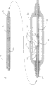
Fig. 2 is the perspective view of radiofrequency catheter ablation of the present invention system;
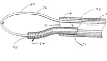
Fig. 3 A stretches out the antenna guide of state and the profile of radio-frequency antenna in the end portion of radiofrequency catheter ablation system;
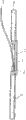
Fig. 3 B is at the antenna guide of the end portion retracted mode of radiofrequency catheter ablation system and the profile of radio-frequency antenna;
Fig. 4 A is the partial sectional view of the end portion of radiofrequency catheter ablation system;
Fig. 4 B is the partial sectional view of end portion of another embodiment of radiofrequency catheter ablation system;
Fig. 5 is the profile of radio-frequency antenna and the partial view of antenna guide;
Fig. 6 is the cutaway view along the 6-6 line of Fig. 5;
Fig. 7 is the perspective view of an alternative embodiment of the invention;
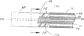
Fig. 8 is the typical cross-section of the end portion of conduit system;
Fig. 9 is the plane graph that is used for little band of the electrical connection between radio-frequency antenna and the source of radio frequency energy;
Figure 10 is the front view of little band of Fig. 9;
Figure 11 is the partial sectional view of radiofrequency catheter ablation system;
Figure 12 is the partial sectional view of the handle frame that uses in the radiofrequency catheter ablation system;
Figure 13 is arranged on the cross-sectional view of the little band in the handle frame of Figure 12;
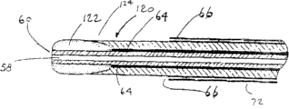
Figure 14 is the partial sectional view in conjunction with an alternative embodiment of the invention of a monopolar radio frequency Antenna Design;
Figure 15 is the partial sectional view in conjunction with an alternative embodiment of the invention of a little band flexible circuit radio-frequency antenna design;
Figure 16 is the cross-sectional view along little band flexible circuit of the 16-16 line of Figure 15;
Figure 17 is the partial sectional view of the end portion of the hollow cable of the present invention that uses in radiofrequency catheter ablation system;
Figure 18 is the partial sectional view in conjunction with the end portion of the conduit of the present invention of one or more leading lines;
Figure 19 is by another partial sectional view of the end portion of the conduit of the present invention of one or more leading line deflections.
Detailed description of the present invention
The invention provides a kind of in the patient body organ the improved radiofrequency catheter system of ablate biological tissue.System comprises a conduit that is suitable for inserting in the patient body organ.It is in conjunction with an extensible radio-frequency antenna that is used for transmitting to therapentic part electromagnetic energy.Providing a kind of is used to make antenna along the pinpoint single track guide in the ablation path of hope.The present invention also provides a kind of hollow coaxial cable that is used for conduct electricity magnetic energy.
As Fig. 1, shown in 2 and 3, the present invention includes one and be applicable to the intraorganic conduit 3 of insertion patient's body.Conduit has a flexible slender tube body 10 that has a proximal part 12 and an end portion 14.Inner chamber 16 extends to the end portion (Fig. 3 and 4) that has end openings 18 from the proximal part of conduit.What be positioned at conduit 3 proximal parts 12 is one and is used to hold as the guiding of the necessity that below will be described in more detail and the handle frame 20 of positioning control part.Be combined in conduit 3 near-ends be one be used to connect support ablation process the male part 22 of various electrode (not shown).
The size of conduit 3 is adaptive according to the needs that are fit to the specific medical process, and this is known in medical skill.The body 10 of conduit is generally by constituting with organ environmental organism compatible polymers material.These examples of material comprise, have in various degree radiation opaque, consistency and elasticity, from the Pebax of German Autochem company, polyethylene, polyurethane, polyester, polyimides and polyamide.
In one embodiment of the invention, conduit 3 is a plurality of sections formation that utilize one or more above-mentioned materials, thereby makes the catheter body little by little have more flexible to its end.By hot adhesion, correct connection or binding agent bonding each section combined.Add the braiding enhancement Layer can for the external peripheral surface of body 10, so that conduit obtains the hardness and the torsional strength of extend of hope.This makes conduit can advance and pass the patient's body organ, and makes conduit reverse conveying from the proximal part to the end portion along the length of conduit.
The end portion 14 of conduit 3 is to be made of the softer polymerizable compound that has seldom or do not weave stiffener, so that when the slype of control lead by the organ of tremulous pulse or vein and so on, provide the flexible of hope to allow the terminal deflection or the guiding of conduit.In the present invention, the guiding of conduit realizes that with a backguy 30 as shown in Figure 11, backguy 30 extends to the end portion 14 of conduit 3 from joystick frame 20.At the end of conduit 3, backguy 30 is fixed on the inwall of conduit cavity 16 with welding or other suitable method.
Conduit system 1 of the present invention provides a kind of and has been used for along the efficient apparatus of the predetermined ablation RF of ablation path transmitting tissue antenna.Fig. 1,3A, 4A and 4B show antenna guide or the single track 36 that stretches out on the extended position of the end portion 14 of adjacent pipes 3.As shown in Fig. 3 B, antenna guide or single track 36 also can be withdrawn in the conduit cavity 16.
In one embodiment of the invention, single track 36 comprises a flexible, elongate elements, and it can be made of strip material.As selection, single track 36 also can be made by minor diameter tubing as shown in the drawing like that.The prolongation 42 and 44 of single track 36 oriented proximal extensions in the conduit cavity 16 (Fig. 4 A, 8-10).At handle frame 20, the single track prolongation is fixed to control sliding part 46 and 48 separately.Similar with conduit deflection backguy 30, control sliding part 46 and 48 slidably mates in the longitudinal slot on handle frame 20, as shown in Figure 2, and can move along the Y-direction end or the near-end of conduit 3.Therefore, by moving one or two control sliding part, the single track guide can be set up an extended position as shown in Fig. 2 and Fig. 3 A, or the retracted position shown in Fig. 3 B.In order to stretch out single track 36, one or two control sliding part 46 and 48 is moved with respect to handle frame 20 terminads.In order to withdraw, will to control sliding part and move to proximal direction.Can be with the position of the fixing control of proper device sliding part, for example, loading spring friction fixture etc. are as deflection control or push those used devices of sliding part 32.
Fig. 3 B shows the single track 36 on complete retracted position, in that it is arranged to a kind of U-shaped state that compresses on this position in the conduit cavity 16 of the end portion 14 of conduit 3.Single track 36 has a flat or crooked top 40, thereby on retracted position, the end openings 18 of conduit 3 has been sealed in top 40 in fact, and conduit cavity 16 and biological external environment are isolated.Top 40 also makes conduit become " AT ", and provides a level and smooth end profile to conduit, so that it reduces to pierce through organ when the passage by organ danger.
Top 40 can be generally used for constituting conduit can be compatible with living organism material manufacture.In addition, it can add a kind of radiation opaque material, to help with x-ray or its position in organ of other fluoroscopic equipment identification, as normally used in the prior art.
In order when single track 36 advances, to determine its position in organ, can be on single track 36 with one or more radiation opaque mark installment.As shown in Fig. 1-4, a radiation opaque labelling is combined in the top 40 of single track 36.Utilize the radiation opaque material, top 40 becomes opaque under x-ray or fluoroscopy, thereby helps its position of identification in conduit insertion or tissue ablation process.The structure of this radiation opaque labelling and use are known in the prior art, no longer are described in detail here.
As the modification in a kind of design, can be combined together to form two of a single track independently elongated member constructing antennas guides with end.Can pre-determine according to the required single track profile of application-specific between two elongated members in conjunction with angle.Therefore, for example, little profile (the having extra small cross section) conduit that the intracavity operation is used in organ narrow, elongated member may need relatively little of angle, with the withdrawal of convenient guide rail with stretch out.Fig. 4 B shows an alternative embodiment of the invention, and wherein the end of single track guide 36a is fixed on close end openings 18 places of conduit 3.The other end in conjunction with the single track 36a of an extension 44a is connected in a control sliding part (not shown) at handle frame.This embodiment can stretch out single track with a single control sliding part and withdraws at handle frame.
As shown in Fig. 2-7, the present invention includes near the radio frequency that is used for tissue ablation (RF) antenna 54 the end portion 14 that is arranged on conduit 3.In a representative embodiment of the present invention, RF antenna 54 comprises a conductive material or a conductor strip of twining a spiral winding 56 of formation with spiral form.As well-known in the art, suitable coil coiling diameter, spacing and length, and conductive material or conductor strip select be the design the selection item, they can change according to the requirement of particular process.
As Fig. 2,3 and 4A and 4B shown in, RF antenna 54 comprises spiral winding 56, it has defined the axial passage 58 that holds single track 36.RF antenna 54 is slidably mounted on the single track 36.Therefore, single track has been stipulated its motion.
In order to improve the globality of shape, for RF antenna 54 provides a pipe lining or sleeve pipe 60, its have one from spiral winding 56 to the bendable extension body of proximal extension to the proximal part 12 of conduit 3.Sleeve pipe 60 is made of dielectric material, and it has reduced the probability of the electrical short between the body fluid in the metal surface of spiral winding 56 and the passage 58, and helps the restriction electromagnetic field to leak into outside the passage.
As shown in Fig. 5 and 6, spiral winding 56 is connected to first or interior conducting element or conductor 64 at contact point 65, and conductor 64 is electrically connected to the RF energy that RF power control source 5 provides again.At Fig. 5, among the embodiment shown in 6,11 and 17, inner wire 64 is made of flexible net or braided wire structure, or constitute by a thin film of conductive material, inner wire 64 is centered around on the outer surface 62 of sleeve pipe 60, and from spiral winding 56 to proximal extension to handle frame 20.In this embodiment, inner wire 64 is rendered as an elongate tubular structure.
As shown in Fig. 5 and 6, spiral winding 56 and is connected to outer conductor 66 at contact point 67 on the external peripheral surface of protective finish 68.Outer conductor 66 is electrically connected to the RF energy source that RF power control source 5 provides again.
In the embodiment shown in Fig. 5 and 6, outer conductor 66 is by constituting around the conductive material of dielectric protective finish 68, and from spiral winding 56 to proximal extension to handle frame 20.Outer conductor can be made of braided wire structure or thin film of conductive material.
As shown in Figure 5, spiral winding 56 has applied a polymer dielectric sealant 70 along its external peripheral surface, guaranteeing the structural integrity of spiral winding, and prevents that spiral winding from contacting with biotic environment.Sealant 70 is to constitute by silicon or based on the suitable material of the material of polymer or rubber compound and so on.Equally, provide a trocar sheath 72 that constitutes with similar material, to encapsulate outer conductor 66 and to provide to bioenvironmental electromagnetism and thermal isolation.
As shown in Figure 11, trocar sheath 72 is connected to one and littlely is with 80, littlely is with 80 to be fixed in handle frame 20 slidably, is used for making the displacement of RF antenna axial direction at proximal part, will illustrate in greater detail below.The prolongation 44 of single track 36 arrives the proximal part 12 of conduit 3 to proximal extension in passage 58.Therefore, the invention provides one group of electric conductor, they each all is formed in the elongated tubular structure, and arranges with coaxillay aligned mutual relation basically, formed one from spiral winding 56 to the hollow cable that be used to transmit RF energy of proximal extension to handle frame 20.
At handle frame 20, inner wire 64 and outer conductor 66 are terminal (Figure 11-13) to be connected to a little connecting plate separately 74 and 76 with 80 of impedance matching.Connecting plate is connected to an electric conductor 82 again, for example a solid coaxial cable that extends to an electromagnetic-energy (not shown) from handle frame 20 through electric wire connecting junction 22.At little band, single track 36 passes the sleeve pipe 60 of RF antenna, and this makes it can be connected to a control sliding part.
Littlely slidably mate along the side channel 84 and 86 on the opposing sidewalls 88 and 90 that is contained in assembling block 92a in the handle frame 20 and 92b with 80.For the axially-movable of RF antenna is provided, can make cable 82 with respect to handle frame terminad or near-end motion, to stretch out or the RF antenna of withdrawing.As selection, can with little be fixed in one with 80 can be along the location sliding part (not shown) that longitudinal slot on the handle frame 20 moves.
As mentioned above, can help to place rightly director element by the radiation opaque labelling.In addition, one or more intracardiac electrocardiogrphs (" ECG ") electrode 96 is provided for single track 36, make the doctor can be before tissue ablation and obtain the best afterwards and organize approach degree and electric conductivity, and obtain their active feedback informations.These electrodes are fixed along the length direction of single track 36.The typical case that Fig. 3 A shows a kind of intracardiac electrode 96 arranges, and intracardiac electrode 96 is electrically connected on the conductor that is arranged in the single track 36, so that its terminal is connected to the signal pins (not shown) in the conductor jointer 22.
Conduit can be inserted in the patient's body organ by an opening, makes conduit press close to the destination organization that will ablate in the patient's body organ.Before inserting conduit, director element 36 and RF antenna 54 are withdrawn in the conduit cavity 16, utilize radiation opaque labelling 40 to obtain an AT apex structure, be beneficial to conduit and pass through smoothly.Then, the end portion 14 of conduit 3 is inserted in the opening of health, and operates to arrive near the position that needs to ablate.Direction control is by the spinning movement on the handle frame and uses deflection control piece 32 to finish.
The placement of radiation opaque labelling 40 convenient RF antenna director elements or single track 36 as normally used in the art, can detect the position of radiation opaque labelling 40 with x-ray that is fit to or fluorescent apparatus.After the end portion 14 of conduit 3 being placed near the tissue ablation point, with the control sliding part single track terminad direction is moved, thereby make it stretch out conduit cavity opening 16, obtain above-mentioned prolongation or extended position circular structure.
According to the interior shape and the size of organ, can handle one or two single track control sliding part, to obtain appropriate single track annular size or profile.Obtain annular size or profile with intracardiac ECG electrode 96 further helps, make the doctor that RF antenna guide or single track 36 are aimed at the path of wishing ablation.
For example, under the situation of the atrium of heart, can regulate annular 50 size, meet the profile of atrium inwall, so that at least a portion of annular 50 can lean against on the atrial walls, this has set up the atrium and has contacted with line between the single track.The flexible in-profile that makes annular at least a portion can meet organ of single track 36, and lean against on its inwall.With beating of atrial walls, the single track that contacts with atrial walls also will as one man move, thereby obtain the fixing and stable positioning relation of the organ of handling with hope.
In case obtained the circular contour of single track, and during, will control sliding part 46 and 48 be fixed on the original position of handle controller with hope ablation path parallel alignment.RF antenna 54 terminads are moved, stretch out the end openings of conduit, and use the single track sliding guidance, reach the exact position that needs ablation.After this, tissue ablation can be finished by applying radio frequency.According to specific processing requirements,, apply the RF energy then, the length that can regulate ablation by making the location of RF antenna along annular diverse location.Therefore, can set up long and successive ablation line, the electric pulse of in fact having eliminated between the ablation tissue path leaks.According to the particular procedure requirement, can repeat above-mentioned steps on demand to other position in the atrium.
Fig. 7 shows an alternative embodiment of the invention, and it combines a kind of modification of antenna guide design.In the present embodiment, antenna guide 102 comprises an elongated flexible element with separable end portion 104, and end portion 104 is a terminal with a tip top 106.Tip top 106 is combined with a kind of radiation opaque material, so that help the placement of conduit as described above.The other end of guide 102 arrives the handle frame (not shown) to proximal extension, and the mode that embodiment is the same as previously described is fixed in a positioning control sliding part (not shown).Similarly, before it stretches, antenna guide 102 and RF antenna 110 together can be withdrawn in the inner chamber of conduit 100.
In use, be placed on conduit 100 near the tissue that will ablate after, make antenna guide 102 stretch out conduit cavity 108, tip top 106 can be anchored in the lip-deep crack of organ.Antenna guide 102 flexible makes it can be crooked, conforming to the profile of organ, and sets up guide 102 and contacts with line between the organ.As a result, just can make any relative motion between guide 102 and the organ reduce to minimum.After this, antenna guide 102 can be carried RF antenna 110 and is stretched over outside the conduit cavity 108, along basically with antenna guide 102 and organ between the line path that contacts parallel alignment ablate.
Embodiment as an alternative, radio-frequency antenna of the present invention can be in conjunction with the various different designs of radio-frequency antenna.Figure 14 shows such alternate embodiment.As shown in Figure 14, as above-mentioned spiral winding structure and alternate substituting thereof, provide an antenna 120 that comprises an one pole pearl 122 to conduit system.The one pole pearl is in antenna 120 terminal annular sleeve 60 excircle settings.Sleeve pipe 60 has an inner chamber 58, to hold director element, for example, aforesaid director element or single track 36 or antenna guide 102.
The one pole pearl is connected in inner wire 64, inner wire and outer conductor 66 electric insulations.As mentioned above, when powering up for inner wire 64 and outer conductor 66, produce an electromagnetic field between the outer conductor 66 of one pole pearl 122 and antenna outside, this electromagnetic field can be used for tissue ablation.Therefore, although do not have physics to contact between one pole pearl 122 and the outer conductor 66, can think that they are connected by electric coupling, to generate an electromagnetic field.
Suitably design the shape and size of one pole pearl 122, to optimize radiating pattern, make reflection and voltage standing wave ratio (" VSWR ") minimum simultaneously, as known in the art, realized providing the impedance matching function of the steady transition of mechanical impedance between the medium of the transmission line of supplying with the RF energy and RF energy emission.Preferably suitably design the shape and size of one pole pearl 122, so that the reflection coefficient minimum of antenna system, thereby make VSWR be reduced to about 1: 1.For example, the diameter of one pole pearl 122 increases gradually to its end direction, and terminates in the end openings of sleeve pipe 60 with the diameter that reduces, thereby roughly forms a tear drop shape, as shown in figure 14.
As mentioned above, inner wire and outer conductor all are applicable to and are connected to a RF energy.When powering up, the electromagnetic field of generation extends to quadrature and omnidirectional in the one pole pearl top of one pole bead surface from outer conductor.The electromagnetic field power of emission is in fact perpendicular to the longitudinal axis of RF antenna, thereby to have produced one be the homogeneous energy field on boundary around antenna and with the antenna.
As another alternate embodiment of the present invention, radio-frequency antenna can be in conjunction with a little band flex circuit design, as substituting of above-mentioned spiral winding or one pole pearl.As shown in Figure 15 and 16, little band flexible circuit antenna 132 comprises a pair of conductive microstrip 134 and 136 that is arranged on the space of the antenna end on the dielectric backing 69, backing 69 is the parts as the dielectric material 68 of inner wire 64 coatings, or the prolongation of sleeve pipe 60.Littlely be with 134 and 136 to be connected to inner wire 64 and outer conductor 66, thereby can generate an electromagnetic field at two little interbands when powering up, this electromagnetic field can be used for tissue ablation.
Suitably determine little with interval and size between 134 and 136, thereby can obtain technically from the transition of mechanical impedance in fact stably of conductor 64 and outer conductor 66 and ablated organ.Therefore, preferably as known to technical, little band flexible circuit Antenna Design is reflected the VSWR minimum for making.The size of micro belt conductor should be enough little, to allow needs bending in the above described manner and the deflection according to tissue ablation.
The material that uses in structure one pole or the micro belt conductor comprises biocompatible conductive material, and these examples of material have platinum, gold or silver-colored, or their combination in any, and these materials are biocompatible.As selection, when forming one pole pearl or micro belt conductor, also can use other conductive material that applies biocompatible material.
As selection, as shown in Figure 18 and 19, one or more leads 140 can be installed be connected with one or more electrodes 142 of RF antenna 138 end portion of the present invention, with provide a kind of can be before tissue ablation and obtain the best device of organizing adjacent degree and conductivity measurements afterwards.
In addition, antenna of the present invention can comprise one or more antenna deflection or leading lines that are fixed on the antenna end part, to obtain more obvious antenna pattern or curvature.Figure 18 and 19 shows an example embodiment, one of them deflection wire 144 is fixed in the end portion 146 of antenna 138, and in hollow coaxial cable inner chamber to proximal extension, so that be connected to handle place deflection controlling organization (not shown), and by the control of this controlling organization.Connect the deflection that deflection wire 144 makes it possible to increase at this position antenna in antenna end part 146, as shown in Figure 19.In use, as mentioned above, can extend into the antenna 138 that has this arrangement for deflecting in the body cavity by means of director element or single track 36.When needed, can spur deflection wire 144 to director element 36 withdrawals then, realize the deflection of the increase of radio-frequency antenna.As a result, can make antenna deformation in such a way, so that can enter the zone of otherwise inaccessiable atrium or other organ.
From top explanation, can recognize,, also alleviate these needs though the present invention does not eliminate the needed small repeatedly accurate location of the ablation catheter electrode of prior art.The present invention can place the RF antenna along the track of the antenna guide that defines the tissue ablation path easily.Simultaneously, the present invention has also guaranteed successive ablation path, and has in fact reduced the danger that electric pulse leaks between the ablation point of prior art.Therefore, in fact the present invention has reached and has obtained the purpose of the Maze method of straight line scar, and need not open heart operation.
Although the present invention can carry out various modifications and improvement, and not break away from the spirit and scope of the present invention according to embodiments of the invention and application example explanation.
Claims (10)
1. conduit system based on radio frequency that is used for the intraorganic biological tissue of ablation patient body; Described conduit system comprises the conduit (3) in the organ that inserts the patient; One extensile guide (36); One is used for transmitting to described biological tissue the radio-frequency antenna (54) of radio frequency energy; An and hollow cable (10) that is used for conduction radio frequency energy between source of radio frequency energy and described radio-frequency antenna; Wherein, Described conduit (3) is used for holding described extensile guide (36), described radio-frequency antenna (54) and described hollow cable (10)
Wherein, described source of radio frequency energy is connected in the proximal part of described hollow cable, described radio-frequency antenna is installed on the distal portions of described hollow cable, and described radio-frequency antenna has and be used to axial passage that described extensile guide is passed through, and described hollow cable comprises:
(a) be coupled to the first elongated conductive tubular element (64) of described radio-frequency antenna (54);
(b) be coupled to described radio-frequency antenna (54), and the second elongated conductive tubular element (66) that on the whole length of cable, essentially coaxially is provided with the first elongated conductive tubular element;
(c) be arranged at elongated tubular product such dielectric element (60) between the described first and second elongated conductive tubular elements; And
(d) axial bore (16), portion receives described extensible guide slidably within it,
Wherein, described extensile guide can stretch out to target ablation position from this conduit, and,
Described radio-frequency antenna (54) and hollow cable can be crossed this extensile guide by this hollow cable that slides and stretch out from this conduit.
2. conduit system as claimed in claim 1, wherein at least one in the first and second elongated conductive tubular elements (64,66) formed by the conductor wire net.
3. conduit system as claimed in claim 1, wherein at least one in the first and second elongated conductive tubular elements (64,66) formed by the conductive braided fabric material.
4. conduit system as claimed in claim 1, wherein at least one in the first and second elongated conductive tubular elements (64,66) formed by conductive film material.
5. conduit system as claimed in claim 1, wherein extensile guide (36) is flexible, and is suitable for the shape of this organ after stretching in organ.
6. conduit system as claimed in claim 1, wherein radio-frequency antenna (54) comprises one around the telescopic one pole of tubulose.
7. conduit system as claimed in claim 1, wherein radio-frequency antenna (54) comprises a spiral winding, this spiral winding defines and is used to the passage of allowing that described extensile guide therefrom passes through slidably.
8. conduit system as claimed in claim 6, wherein radio-frequency antenna (54) has tear drop shape.
9. conduit system as claimed in claim 1, wherein radio-frequency antenna (54) is to possess a pair of antenna end and the little band flexible circuit isolated conductive microstrip that is arranged on the dielectric backing (69).
10. conduit system as claimed in claim 1, further comprise the little band of impedance matching (80), the little band of described impedance matching has and connecting plate that with source of radio frequency energy be connected that be connected respectively with the described second elongated conductive tubular element (66) with the described first elongated conductive tubular element (64).
Applications Claiming Priority (2)
| Application Number | Priority Date | Filing Date | Title |
|---|---|---|---|
| US09/211,188 | 1998-12-14 | ||
| US09/211,188 US6190382B1 (en) | 1998-12-14 | 1998-12-14 | Radio-frequency based catheter system for ablation of body tissues |
Related Parent Applications (1)
| Application Number | Title | Priority Date | Filing Date |
|---|---|---|---|
| CNB998028908A Division CN1283212C (en) | 1998-12-14 | 1999-12-08 | Radio-frequency based catheter system and hollow co-axial cable for ablation of body tissues |
Publications (2)
| Publication Number | Publication Date |
|---|---|
| CN1943523A CN1943523A (en) | 2007-04-11 |
| CN100558308C true CN100558308C (en) | 2009-11-11 |
Family
ID=22785906
Family Applications (2)
| Application Number | Title | Priority Date | Filing Date |
|---|---|---|---|
| CNB998028908A Expired - Lifetime CN1283212C (en) | 1998-12-14 | 1999-12-08 | Radio-frequency based catheter system and hollow co-axial cable for ablation of body tissues |
| CNB2006101388062A Expired - Lifetime CN100558308C (en) | 1998-12-14 | 1999-12-08 | Systemic conduit system and hollow coaxial cable based on radio frequency are used to ablate |
Family Applications Before (1)
| Application Number | Title | Priority Date | Filing Date |
|---|---|---|---|
| CNB998028908A Expired - Lifetime CN1283212C (en) | 1998-12-14 | 1999-12-08 | Radio-frequency based catheter system and hollow co-axial cable for ablation of body tissues |
Country Status (11)
| Country | Link |
|---|---|
| US (2) | US6190382B1 (en) |
| EP (2) | EP1054639B8 (en) |
| JP (2) | JP2002532132A (en) |
| KR (1) | KR100550164B1 (en) |
| CN (2) | CN1283212C (en) |
| AT (1) | ATE297167T1 (en) |
| AU (1) | AU3115200A (en) |
| CA (1) | CA2321413C (en) |
| DE (2) | DE69925715T2 (en) |
| HK (1) | HK1037313A1 (en) |
| WO (1) | WO2000035363A1 (en) |
Families Citing this family (221)
| Publication number | Priority date | Publication date | Assignee | Title |
|---|---|---|---|---|
| US7022105B1 (en) * | 1996-05-06 | 2006-04-04 | Novasys Medical Inc. | Treatment of tissue in sphincters, sinuses and orifices |
| US8353908B2 (en) * | 1996-09-20 | 2013-01-15 | Novasys Medical, Inc. | Treatment of tissue in sphincters, sinuses, and orifices |
| US6702789B1 (en) | 1997-03-11 | 2004-03-09 | Alcove Medical, Inc. | Catheter having insertion control mechanism and anti-bunching mechanism |
| US9023031B2 (en) * | 1997-08-13 | 2015-05-05 | Verathon Inc. | Noninvasive devices, methods, and systems for modifying tissues |
| US6645200B1 (en) | 1997-10-10 | 2003-11-11 | Scimed Life Systems, Inc. | Method and apparatus for positioning a diagnostic or therapeutic element within the body and tip electrode for use with same |
| US20100114087A1 (en) * | 1998-02-19 | 2010-05-06 | Edwards Stuart D | Methods and devices for treating urinary incontinence |
| US6245062B1 (en) * | 1998-10-23 | 2001-06-12 | Afx, Inc. | Directional reflector shield assembly for a microwave ablation instrument |
| US20070066972A1 (en) * | 2001-11-29 | 2007-03-22 | Medwaves, Inc. | Ablation catheter apparatus with one or more electrodes |
| US7070595B2 (en) * | 1998-12-14 | 2006-07-04 | Medwaves, Inc. | Radio-frequency based catheter system and method for ablating biological tissues |
| US7594913B2 (en) * | 1998-12-14 | 2009-09-29 | Medwaves, Inc. | Radio-frequency based catheter system and method for ablating biological tissues |
| US7449019B2 (en) * | 1999-01-25 | 2008-11-11 | Smith & Nephew, Inc. | Intervertebral decompression |
| US7226446B1 (en) * | 1999-05-04 | 2007-06-05 | Dinesh Mody | Surgical microwave ablation assembly |
| US6277113B1 (en) * | 1999-05-28 | 2001-08-21 | Afx, Inc. | Monopole tip for ablation catheter and methods for using same |
| US6529756B1 (en) * | 1999-11-22 | 2003-03-04 | Scimed Life Systems, Inc. | Apparatus for mapping and coagulating soft tissue in or around body orifices |
| US6613046B1 (en) | 1999-11-22 | 2003-09-02 | Scimed Life Systems, Inc. | Loop structures for supporting diagnostic and therapeutic elements in contact with body tissue |
| US7033352B1 (en) * | 2000-01-18 | 2006-04-25 | Afx, Inc. | Flexible ablation instrument |
| US6673068B1 (en) * | 2000-04-12 | 2004-01-06 | Afx, Inc. | Electrode arrangement for use in a medical instrument |
| AU7346801A (en) * | 2000-07-13 | 2002-01-30 | Transurgical Inc | Energy application with inflatable annular lens |
| CN1241658C (en) | 2000-07-13 | 2006-02-15 | 普罗里森姆股份有限公司 | Thermal treatment method and apparatus with focused energy application |
| US7306591B2 (en) | 2000-10-02 | 2007-12-11 | Novasys Medical, Inc. | Apparatus and methods for treating female urinary incontinence |
| KR20010000523A (en) * | 2000-10-04 | 2001-01-05 | 김용성 | Operating method for remove wrinkle with Radio Frequency |
| US6916306B1 (en) * | 2000-11-10 | 2005-07-12 | Boston Scientific Scimed, Inc. | Steerable loop structures for supporting diagnostic and therapeutic elements in contact with body tissue |
| IL140136A (en) * | 2000-12-06 | 2010-06-16 | Intumed Ltd | Apparatus for self-guided intubation |
| US20020087151A1 (en) * | 2000-12-29 | 2002-07-04 | Afx, Inc. | Tissue ablation apparatus with a sliding ablation instrument and method |
| US20030163128A1 (en) * | 2000-12-29 | 2003-08-28 | Afx, Inc. | Tissue ablation system with a sliding ablating device and method |
| US7439319B2 (en) * | 2001-09-14 | 2008-10-21 | Burnham Institute For Medical Research | Selective substrates for matrix metalloproteinases |
| ATE375127T1 (en) * | 2001-11-29 | 2007-10-15 | Medwaves Inc | HIGH FREQUENCY CATHETER SYSTEM WITH IMPROVED DEFLECTION AND CONTROL MECHANISMS |
| US20040215310A1 (en) * | 2002-01-17 | 2004-10-28 | Omar Amirana | Stent and delivery method for applying RF energy to a pulmonary vein and the atrial wall around its ostium to eliminate atrial fibrillation while preventing stenosis of the pulmonary vein thereafter |
| US6814733B2 (en) | 2002-01-31 | 2004-11-09 | Biosense, Inc. | Radio frequency pulmonary vein isolation |
| US20050075629A1 (en) * | 2002-02-19 | 2005-04-07 | Afx, Inc. | Apparatus and method for assessing tissue ablation transmurality |
| DE10212841B4 (en) * | 2002-03-22 | 2011-02-24 | Karl Storz Gmbh & Co. Kg | Medical instrument for the treatment of tissue by means of high frequency current and medical system with such a medical instrument |
| US6893442B2 (en) | 2002-06-14 | 2005-05-17 | Ablatrics, Inc. | Vacuum coagulation probe for atrial fibrillation treatment |
| US8235990B2 (en) | 2002-06-14 | 2012-08-07 | Ncontact Surgical, Inc. | Vacuum coagulation probes |
| US7572257B2 (en) * | 2002-06-14 | 2009-08-11 | Ncontact Surgical, Inc. | Vacuum coagulation and dissection probes |
| US9439714B2 (en) * | 2003-04-29 | 2016-09-13 | Atricure, Inc. | Vacuum coagulation probes |
| US7063698B2 (en) * | 2002-06-14 | 2006-06-20 | Ncontact Surgical, Inc. | Vacuum coagulation probes |
| US20040106937A1 (en) * | 2002-06-21 | 2004-06-03 | Afx, Inc. | Clamp accessory and method for an ablation instrument |
| US20040082859A1 (en) | 2002-07-01 | 2004-04-29 | Alan Schaer | Method and apparatus employing ultrasound energy to treat body sphincters |
| US20040054350A1 (en) * | 2002-09-17 | 2004-03-18 | Shaughnessy Michael C. | Enteral feeding unit having a reflux device and reflux method |
| US6997924B2 (en) | 2002-09-17 | 2006-02-14 | Biosense Inc. | Laser pulmonary vein isolation |
| US7156816B2 (en) * | 2002-11-26 | 2007-01-02 | Biosense, Inc. | Ultrasound pulmonary vein isolation |
| US7351202B2 (en) * | 2002-12-05 | 2008-04-01 | Ethicon Endo-Surgery, Inc. | Medical device with track and method of use |
| US7226410B2 (en) * | 2002-12-05 | 2007-06-05 | Ethicon-Endo Surgery, Inc. | Locally-propelled, intraluminal device with cable loop track and method of use |
| US20040116899A1 (en) * | 2002-12-16 | 2004-06-17 | Shaughnessy Michael C. | Bolus for non-occluding high flow enteral feeding tube |
| US20040162507A1 (en) * | 2003-02-19 | 2004-08-19 | Assaf Govari | Externally-applied high intensity focused ultrasound (HIFU) for therapeutic treatment |
| US7201749B2 (en) * | 2003-02-19 | 2007-04-10 | Biosense, Inc. | Externally-applied high intensity focused ultrasound (HIFU) for pulmonary vein isolation |
| WO2004073505A2 (en) * | 2003-02-20 | 2004-09-02 | Prorhythm, Inc. | Cardiac ablation devices |
| GB0307715D0 (en) * | 2003-04-03 | 2003-05-07 | Ethicon Endo Surgery Inc | Guide wire structure for insertion into an internal space |
| AU2004227926B2 (en) * | 2003-04-03 | 2011-01-20 | Ethicon Endo-Surgery, Inc. | Guide wire structure for insertion into an internal space |
| US7455643B1 (en) | 2003-07-07 | 2008-11-25 | Nellcor Puritan Bennett Ireland | Continuous non-invasive blood pressure measurement apparatus and methods providing automatic recalibration |
| US6973339B2 (en) * | 2003-07-29 | 2005-12-06 | Biosense, Inc | Lasso for pulmonary vein mapping and ablation |
| US7367970B2 (en) * | 2003-11-11 | 2008-05-06 | Biosense Webster Inc. | Externally applied RF for pulmonary vein isolation |
| US7182762B2 (en) * | 2003-12-30 | 2007-02-27 | Smith & Nephew, Inc. | Electrosurgical device |
| US7244254B2 (en) * | 2004-04-29 | 2007-07-17 | Micrablate | Air-core microwave ablation antennas |
| US7467015B2 (en) | 2004-04-29 | 2008-12-16 | Neuwave Medical, Inc. | Segmented catheter for tissue ablation |
| WO2005113051A2 (en) * | 2004-05-14 | 2005-12-01 | Ethicon Endo-Surgery, Inc. | Medical instrument having a medical guidewire |
| US7758564B2 (en) * | 2004-05-14 | 2010-07-20 | Ethicon Endo-Surgery, Inc. | Medical instrument having a catheter and a medical guidewire |
| US8070693B2 (en) * | 2004-09-30 | 2011-12-06 | Cook Medical Technologies Llc | Articulating steerable wire guide |
| EP1658818A1 (en) | 2004-11-23 | 2006-05-24 | Biosense Webster, Inc. | Externally applied rf for pulmonary vein isolation |
| AU2005312310A1 (en) * | 2004-12-03 | 2006-06-08 | Duoject Medical Systems Inc. | Cartridge, device and method for pharmaceutical storage, mixing and delivery |
| US7976518B2 (en) * | 2005-01-13 | 2011-07-12 | Corpak Medsystems, Inc. | Tubing assembly and signal generator placement control device and method for use with catheter guidance systems |
| US20060217687A1 (en) * | 2005-03-24 | 2006-09-28 | Ethicon Endo-Surgery, Inc. | Catheter-gripping device which measures insertion force during a medical procedure |
| WO2006127847A2 (en) * | 2005-05-24 | 2006-11-30 | Micrablate, Llc | Microwave surgical device |
| WO2006138382A2 (en) | 2005-06-14 | 2006-12-28 | Micrablate, Llc | Microwave tissue resection tool |
| US7536218B2 (en) * | 2005-07-15 | 2009-05-19 | Biosense Webster, Inc. | Hybrid magnetic-based and impedance-based position sensing |
| US20070060898A1 (en) * | 2005-09-07 | 2007-03-15 | Shaughnessy Michael C | Enteral medical treatment assembly having a safeguard against erroneous connection with an intravascular treatment system |
| AU2006302057B2 (en) | 2005-10-11 | 2013-03-21 | Carnegie Mellon University | Sensor guided catheter navigation system |
| KR100778142B1 (en) * | 2005-11-09 | 2007-11-29 | 황창모 | Radio frequency ablation electrode for selected tissue removal |
| US7819802B2 (en) * | 2005-11-22 | 2010-10-26 | General Electric Company | Catheter tip |
| US7918850B2 (en) | 2006-02-17 | 2011-04-05 | Biosense Wabster, Inc. | Lesion assessment by pacing |
| WO2007112102A1 (en) | 2006-03-24 | 2007-10-04 | Micrablate | Center fed dipole for use with tissue ablation systems, devices, and methods |
| US10363092B2 (en) | 2006-03-24 | 2019-07-30 | Neuwave Medical, Inc. | Transmission line with heat transfer ability |
| EP1998699A1 (en) * | 2006-03-24 | 2008-12-10 | Neuwave Medical, Inc. | Energy delivery system |
| US8211114B2 (en) | 2006-04-24 | 2012-07-03 | Ethicon Endo-Surgery, Inc. | Medical instrument having a medical snare |
| US9138250B2 (en) | 2006-04-24 | 2015-09-22 | Ethicon Endo-Surgery, Inc. | Medical instrument handle and medical instrument having a handle |
| US7837620B2 (en) | 2006-04-25 | 2010-11-23 | Ethicon Endo-Surgery, Inc. | Medical tubular assembly |
| US7927327B2 (en) | 2006-04-25 | 2011-04-19 | Ethicon Endo-Surgery, Inc. | Medical instrument having an articulatable end effector |
| US7959642B2 (en) | 2006-05-16 | 2011-06-14 | Ethicon Endo-Surgery, Inc. | Medical instrument having a needle knife |
| US7892166B2 (en) | 2006-05-18 | 2011-02-22 | Ethicon Endo-Surgery, Inc. | Medical instrument including a catheter having a catheter stiffener and method for using |
| US10499937B2 (en) * | 2006-05-19 | 2019-12-10 | Recor Medical, Inc. | Ablation device with optimized input power profile and method of using the same |
| US20070299403A1 (en) * | 2006-06-23 | 2007-12-27 | Crowe John E | Directional introducer |
| US11389235B2 (en) | 2006-07-14 | 2022-07-19 | Neuwave Medical, Inc. | Energy delivery systems and uses thereof |
| US10376314B2 (en) | 2006-07-14 | 2019-08-13 | Neuwave Medical, Inc. | Energy delivery systems and uses thereof |
| DE102006034389B4 (en) * | 2006-07-25 | 2018-06-07 | Siemens Healthcare Gmbh | Catheter for use in magnetic resonance assisted interventional procedures |
| US8002714B2 (en) * | 2006-08-17 | 2011-08-23 | Ethicon Endo-Surgery, Inc. | Guidewire structure including a medical guidewire and method for using a medical instrument |
| WO2008021321A2 (en) * | 2006-08-17 | 2008-02-21 | Rjf Holdings Iv, Inc | Method and apparatus for plasma incision of cardiovascular tissue |
| US20080045863A1 (en) * | 2006-08-17 | 2008-02-21 | Ethicon Endo-Surgery, Inc. | Guidewire structure including a medical guidewire |
| US8715205B2 (en) * | 2006-08-25 | 2014-05-06 | Cook Medical Tecnologies Llc | Loop tip wire guide |
| US20080097331A1 (en) * | 2006-09-05 | 2008-04-24 | Ethicon Endo-Surgery, Inc. | Guidewire structure including a medical guidewire and method for using |
| US20080064920A1 (en) * | 2006-09-08 | 2008-03-13 | Ethicon Endo-Surgery, Inc. | Medical drive system for providing motion to at least a portion of a medical apparatus |
| US8197494B2 (en) | 2006-09-08 | 2012-06-12 | Corpak Medsystems, Inc. | Medical device position guidance system with wireless connectivity between a noninvasive device and an invasive device |
| US20080094228A1 (en) * | 2006-10-12 | 2008-04-24 | Welch James P | Patient monitor using radio frequency identification tags |
| US10932848B2 (en) | 2007-02-06 | 2021-03-02 | Microcube, Llc | Delivery system for delivering a medical device to a location within a patient's body |
| WO2008098074A2 (en) | 2007-02-06 | 2008-08-14 | Microcube, Llc | A delivery system for delivering a medical device to a location within a patient's body |
| EP2008598A1 (en) * | 2007-06-29 | 2008-12-31 | Edward A. Loeser | Composite fiber electrosurgical instrument |
| US8929988B2 (en) | 2007-07-11 | 2015-01-06 | Apollo Endosurgery, Inc. | Methods and systems for submucosal implantation of a device for diagnosis and treatment of a body |
| US8317771B2 (en) * | 2007-07-11 | 2012-11-27 | Apollo Endosurgery, Inc. | Methods and systems for performing submucosal medical procedures |
| US8128592B2 (en) | 2007-07-11 | 2012-03-06 | Apollo Endosurgery, Inc. | Methods and systems for performing submucosal medical procedures |
| US20100217151A1 (en) * | 2007-07-11 | 2010-08-26 | Zach Gostout | Methods and Systems for Performing Submucosal Medical Procedures |
| US8066689B2 (en) | 2007-07-11 | 2011-11-29 | Apollo Endosurgery, Inc. | Methods and systems for submucosal implantation of a device for diagnosis and treatment with a therapeutic agent |
| US20090082762A1 (en) * | 2007-09-20 | 2009-03-26 | Ormsby Theodore C | Radio frequency energy transmission device for the ablation of biological tissues |
| KR100954285B1 (en) * | 2007-12-04 | 2010-04-23 | 연세대학교 산학협력단 | Operation device of radiofrequency ablation comprised flexible tube |
| KR100949996B1 (en) | 2008-02-28 | 2010-03-26 | (주)트리플씨메디칼 | Electrosurgical unit using radiofrequency, and method of surgery using radiofrequency |
| US20090287045A1 (en) | 2008-05-15 | 2009-11-19 | Vladimir Mitelberg | Access Systems and Methods of Intra-Abdominal Surgery |
| US8133222B2 (en) * | 2008-05-28 | 2012-03-13 | Medwaves, Inc. | Tissue ablation apparatus and method using ultrasonic imaging |
| US8398556B2 (en) * | 2008-06-30 | 2013-03-19 | Covidien Lp | Systems and methods for non-invasive continuous blood pressure determination |
| US8660799B2 (en) | 2008-06-30 | 2014-02-25 | Nellcor Puritan Bennett Ireland | Processing and detecting baseline changes in signals |
| US20090326386A1 (en) * | 2008-06-30 | 2009-12-31 | Nellcor Puritan Bennett Ireland | Systems and Methods for Non-Invasive Blood Pressure Monitoring |
| US8679106B2 (en) * | 2008-07-01 | 2014-03-25 | Medwaves, Inc. | Angioplasty and tissue ablation apparatus and method |
| US8506498B2 (en) | 2008-07-15 | 2013-08-13 | Nellcor Puritan Bennett Ireland | Systems and methods using induced perturbation to determine physiological parameters |
| US20100016784A1 (en) | 2008-07-17 | 2010-01-21 | Microcube Llc | Positionable medical system for positioning medical components on or within a body |
| US9314168B2 (en) * | 2008-09-30 | 2016-04-19 | Nellcor Puritan Bennett Ireland | Detecting sleep events using localized blood pressure changes |
| US9687161B2 (en) * | 2008-09-30 | 2017-06-27 | Nellcor Puritan Bennett Ireland | Systems and methods for maintaining blood pressure monitor calibration |
| US8532751B2 (en) * | 2008-09-30 | 2013-09-10 | Covidien Lp | Laser self-mixing sensors for biological sensing |
| US9301697B2 (en) * | 2008-09-30 | 2016-04-05 | Nellcor Puritan Bennett Ireland | Systems and methods for recalibrating a non-invasive blood pressure monitor |
| US11219484B2 (en) | 2008-10-21 | 2022-01-11 | Microcube, Llc | Methods and devices for delivering microwave energy |
| US11291503B2 (en) * | 2008-10-21 | 2022-04-05 | Microcube, Llc | Microwave treatment devices and methods |
| CN102245119B (en) * | 2008-10-21 | 2017-06-06 | 微立方有限责任公司 | Energy is applied to the method and device of bodily tissue |
| US9980774B2 (en) * | 2008-10-21 | 2018-05-29 | Microcube, Llc | Methods and devices for delivering microwave energy |
| WO2010048334A1 (en) * | 2008-10-21 | 2010-04-29 | Microcube, Llc | Microwave treatment devices and methods |
| CN102256560B (en) * | 2008-11-10 | 2014-07-09 | 微立方有限责任公司 | Methods and devices for applying energy to bodily tissues |
| US11376061B2 (en) * | 2008-11-11 | 2022-07-05 | Covidien Lp | Energy delivery device and methods of use |
| WO2010080886A1 (en) * | 2009-01-09 | 2010-07-15 | Recor Medical, Inc. | Methods and apparatus for treatment of mitral valve in insufficiency |
| US8216136B2 (en) | 2009-03-05 | 2012-07-10 | Nellcor Puritan Bennett Llc | Systems and methods for monitoring heart rate and blood pressure correlation |
| US8934989B2 (en) * | 2009-04-15 | 2015-01-13 | Medwaves, Inc. | Radio frequency based ablation system and method with dielectric transformer |
| US9326819B2 (en) * | 2009-04-15 | 2016-05-03 | Medwaves, Inc. | Electrically tunable tissue ablation system and method |
| US9107666B2 (en) | 2009-04-17 | 2015-08-18 | Domain Surgical, Inc. | Thermal resecting loop |
| US9265556B2 (en) | 2009-04-17 | 2016-02-23 | Domain Surgical, Inc. | Thermally adjustable surgical tool, balloon catheters and sculpting of biologic materials |
| US9131977B2 (en) | 2009-04-17 | 2015-09-15 | Domain Surgical, Inc. | Layered ferromagnetic coated conductor thermal surgical tool |
| US9078655B2 (en) | 2009-04-17 | 2015-07-14 | Domain Surgical, Inc. | Heated balloon catheter |
| US9730749B2 (en) | 2009-04-17 | 2017-08-15 | Domain Surgical, Inc. | Surgical scalpel with inductively heated regions |
| US20100324431A1 (en) * | 2009-06-18 | 2010-12-23 | Nellcor Puritan Bennett Ireland | Determining Disease State Using An Induced Load |
| US9198582B2 (en) * | 2009-06-30 | 2015-12-01 | Nellcor Puritan Bennett Ireland | Determining a characteristic physiological parameter |
| US8290730B2 (en) * | 2009-06-30 | 2012-10-16 | Nellcor Puritan Bennett Ireland | Systems and methods for assessing measurements in physiological monitoring devices |
| US20110021929A1 (en) * | 2009-07-27 | 2011-01-27 | Nellcor Puritan Bennett Ireland | Systems and methods for continuous non-invasive blood pressure monitoring |
| EP2459096B1 (en) | 2009-07-28 | 2014-10-22 | Neuwave Medical, Inc. | Ablation device |
| US8628477B2 (en) * | 2009-07-31 | 2014-01-14 | Nellcor Puritan Bennett Ireland | Systems and methods for non-invasive determination of blood pressure |
| US9220440B2 (en) * | 2009-09-21 | 2015-12-29 | Nellcor Puritan Bennett Ireland | Determining a characteristic respiration rate |
| US9066660B2 (en) * | 2009-09-29 | 2015-06-30 | Nellcor Puritan Bennett Ireland | Systems and methods for high-pass filtering a photoplethysmograph signal |
| US8463347B2 (en) * | 2009-09-30 | 2013-06-11 | Nellcor Puritan Bennett Ireland | Systems and methods for normalizing a plethysmograph signal for improved feature analysis |
| US8409098B2 (en) * | 2009-10-14 | 2013-04-02 | St. Jude Medical, Atrial Fibrillation Division, Inc. | Method and apparatus for collection of cardiac geometry based on optical or magnetic tracking |
| US10660697B2 (en) | 2009-11-10 | 2020-05-26 | Cardea Medsystems (Tianjin) Co., Ltd. | Hollow body cavity ablation apparatus |
| WO2011059487A2 (en) * | 2009-11-10 | 2011-05-19 | Cardea MedSystems, Inc. | Hollow body cavity ablation apparatus |
| CN102711648B (en) * | 2009-11-30 | 2015-07-29 | 麦迪威公司 | There is the radio frequency ablation system of tracking transducer |
| US9451887B2 (en) | 2010-03-31 | 2016-09-27 | Nellcor Puritan Bennett Ireland | Systems and methods for measuring electromechanical delay of the heart |
| US8898037B2 (en) | 2010-04-28 | 2014-11-25 | Nellcor Puritan Bennett Ireland | Systems and methods for signal monitoring using Lissajous figures |
| ES2856026T3 (en) | 2010-05-03 | 2021-09-27 | Neuwave Medical Inc | Power supply systems |
| US9173705B2 (en) | 2010-05-13 | 2015-11-03 | Ncontact Surgical, Inc. | Subxyphoid epicardial ablation |
| US8672933B2 (en) * | 2010-06-30 | 2014-03-18 | Covidien Lp | Microwave antenna having a reactively-loaded loop configuration |
| EP2640280B1 (en) | 2010-11-16 | 2022-03-16 | TVA Medical, Inc. | Devices for forming a fistula |
| US8825428B2 (en) | 2010-11-30 | 2014-09-02 | Neilcor Puritan Bennett Ireland | Methods and systems for recalibrating a blood pressure monitor with memory |
| US9259160B2 (en) | 2010-12-01 | 2016-02-16 | Nellcor Puritan Bennett Ireland | Systems and methods for determining when to measure a physiological parameter |
| US9357934B2 (en) | 2010-12-01 | 2016-06-07 | Nellcor Puritan Bennett Ireland | Systems and methods for physiological event marking |
| AU2015202149B2 (en) * | 2011-04-08 | 2016-11-17 | Covidien Lp | Flexible microwave catheters for natural or artificial lumens |
| JP5763263B2 (en) | 2011-04-08 | 2015-08-12 | コビディエン エルピー | Flexible microwave catheter for natural or artificial lumens |
| US8932279B2 (en) | 2011-04-08 | 2015-01-13 | Domain Surgical, Inc. | System and method for cooling of a heated surgical instrument and/or surgical site and treating tissue |
| US8915909B2 (en) | 2011-04-08 | 2014-12-23 | Domain Surgical, Inc. | Impedance matching circuit |
| US8663190B2 (en) | 2011-04-22 | 2014-03-04 | Ablative Solutions, Inc. | Expandable catheter system for peri-ostial injection and muscle and nerve fiber ablation |
| US9240630B2 (en) | 2011-04-29 | 2016-01-19 | Cyberonics, Inc. | Antenna shield for an implantable medical device |
| US9089712B2 (en) | 2011-04-29 | 2015-07-28 | Cyberonics, Inc. | Implantable medical device without antenna feedthrough |
| US9259582B2 (en) | 2011-04-29 | 2016-02-16 | Cyberonics, Inc. | Slot antenna for an implantable device |
| US9265958B2 (en) | 2011-04-29 | 2016-02-23 | Cyberonics, Inc. | Implantable medical device antenna |
| WO2012158722A2 (en) | 2011-05-16 | 2012-11-22 | Mcnally, David, J. | Surgical instrument guide |
| EP2742893B1 (en) * | 2011-08-10 | 2016-10-19 | National University Corporation Shiga University OF Medical Science | Microwave surgical instrument |
| US20130053792A1 (en) | 2011-08-24 | 2013-02-28 | Ablative Solutions, Inc. | Expandable catheter system for vessel wall injection and muscle and nerve fiber ablation |
| CN102397099A (en) * | 2011-08-30 | 2012-04-04 | 北京工业大学 | Aneurysm interventional thermotherapy device |
| CN102319114A (en) * | 2011-09-02 | 2012-01-18 | 王宝根 | Wicresoft's hoe scaler resets under the multi-functional scope |
| WO2013040255A2 (en) | 2011-09-13 | 2013-03-21 | Domain Surgical, Inc. | Sealing and/or cutting instrument |
| US9060695B2 (en) | 2011-11-30 | 2015-06-23 | Covidien Lp | Systems and methods for determining differential pulse transit time from the phase difference of two analog plethysmographs |
| KR20140102668A (en) | 2011-12-06 | 2014-08-22 | 도메인 서지컬, 인크. | System and method of controlling power delivery to a surgical instrument |
| EP3769712A1 (en) | 2011-12-21 | 2021-01-27 | Neuwave Medical, Inc. | Energy delivery systems |
| US8403927B1 (en) | 2012-04-05 | 2013-03-26 | William Bruce Shingleton | Vasectomy devices and methods |
| CN104203136A (en) * | 2012-04-16 | 2014-12-10 | 波士顿科学西美德公司 | Helical tubing devices for fluid renal nerve modulation |
| US9375249B2 (en) * | 2012-05-11 | 2016-06-28 | Covidien Lp | System and method for directing energy to tissue |
| GB201217781D0 (en) * | 2012-10-04 | 2012-11-14 | Gyrus Medical Ltd | Electrosurgical apparatus and system |
| US9486276B2 (en) | 2012-10-11 | 2016-11-08 | Tva Medical, Inc. | Devices and methods for fistula formation |
| US10945787B2 (en) | 2012-10-29 | 2021-03-16 | Ablative Solutions, Inc. | Peri-vascular tissue ablation catheters |
| US9526827B2 (en) | 2012-10-29 | 2016-12-27 | Ablative Solutions, Inc. | Peri-vascular tissue ablation catheter with support structures |
| US9364277B2 (en) | 2012-12-13 | 2016-06-14 | Cook Medical Technologies Llc | RF energy controller and method for electrosurgical medical devices |
| US9204921B2 (en) | 2012-12-13 | 2015-12-08 | Cook Medical Technologies Llc | RF energy controller and method for electrosurgical medical devices |
| AU2014236149A1 (en) | 2013-03-14 | 2015-09-17 | Tva Medical, Inc. | Fistula formation devices and methods therefor |
| GB201312416D0 (en) | 2013-07-11 | 2013-08-28 | Creo Medical Ltd | Electrosurgical Device |
| EP3049005B1 (en) | 2013-09-24 | 2022-08-10 | Adagio Medical, Inc. | Endovascular near critical fluid based cryoablation catheter |
| US9931046B2 (en) | 2013-10-25 | 2018-04-03 | Ablative Solutions, Inc. | Intravascular catheter with peri-vascular nerve activity sensors |
| US9949652B2 (en) | 2013-10-25 | 2018-04-24 | Ablative Solutions, Inc. | Apparatus for effective ablation and nerve sensing associated with denervation |
| US10517666B2 (en) | 2013-10-25 | 2019-12-31 | Ablative Solutions, Inc. | Apparatus for effective ablation and nerve sensing associated with denervation |
| EP2881057A1 (en) | 2013-12-05 | 2015-06-10 | Region Nordjylland | Apparatus for creating linear lesions in body tissue within a body vessel |
| WO2015138998A1 (en) | 2014-03-14 | 2015-09-17 | Tva Medical, Inc. | Fistula formation devices and methods therefor |
| EP3131487A4 (en) | 2014-04-17 | 2017-12-13 | Adagio Medical, Inc. | Endovascular near critical fluid based cryoablation catheter having plurality of preformed treatment shapes |
| US10357306B2 (en) | 2014-05-14 | 2019-07-23 | Domain Surgical, Inc. | Planar ferromagnetic coated surgical tip and method for making |
| FR3023157B1 (en) * | 2014-07-06 | 2019-01-25 | Ab Medica | DEVICE FOR REALIZING THE RESECTION OF AN ORGAN IN A CAVITY OF A LIVING BODY |
| US10646666B2 (en) | 2014-08-27 | 2020-05-12 | Tva Medical, Inc. | Cryolipolysis devices and methods therefor |
| GB201418474D0 (en) * | 2014-10-17 | 2014-12-03 | Creo Medical Ltd | Electrosurgical apparatus |
| EP3217903A4 (en) | 2014-11-13 | 2018-05-30 | Adagio Medical, Inc. | Pressure modulated cryoablation system and related methods |
| US10603040B1 (en) | 2015-02-09 | 2020-03-31 | Tva Medical, Inc. | Methods for treating hypertension and reducing blood pressure with formation of fistula |
| US10888374B2 (en) * | 2015-07-08 | 2021-01-12 | The Johns Hopkins University | Tissue ablation and assessment system and method of use thereof |
| US11051867B2 (en) | 2015-09-18 | 2021-07-06 | Adagio Medical, Inc. | Tissue contact verification system |
| EP3367942B1 (en) | 2015-10-26 | 2021-01-20 | Neuwave Medical, Inc. | Energy delivery systems |
| GB2545179B (en) * | 2015-12-07 | 2020-09-09 | Creo Medical Ltd | Electrosurgical instrument |
| DE102015016060A1 (en) * | 2015-12-11 | 2017-06-14 | Olympus Winter & Ibe Gmbh | SURGICAL VAPORIZATION ELECTRODE |
| EP3402561B1 (en) | 2016-01-15 | 2024-02-28 | TVA Medical, Inc. | Devices for advancing a wire |
| WO2017124062A1 (en) | 2016-01-15 | 2017-07-20 | Tva Medical, Inc. | Devices and methods for forming a fistula |
| US10874422B2 (en) | 2016-01-15 | 2020-12-29 | Tva Medical, Inc. | Systems and methods for increasing blood flow |
| ES2854935T3 (en) | 2016-04-15 | 2021-09-23 | Neuwave Medical Inc | Power delivery system |
| CN105963013B (en) * | 2016-06-13 | 2019-01-04 | 北京米道斯医疗器械有限公司 | A kind of low temperature endoscopic vessel acquisition device and method |
| JP7194676B2 (en) | 2016-09-25 | 2022-12-22 | ティーブイエー メディカル, インコーポレイテッド | Vascular stent device and method |
| GB2559604A (en) * | 2017-02-13 | 2018-08-15 | Creo Medical Ltd | Microwave energy transfer component for electrosurgical apparatus |
| GB2562110A (en) * | 2017-05-05 | 2018-11-07 | Creo Medical Ltd | Apparatus for sterilising an instrument channel of a surgical scoping device |
| AU2018328115A1 (en) | 2017-09-05 | 2020-04-02 | Adagio Medical, Inc. | Ablation catheter having a shape memory stylet |
| EP3723633B1 (en) * | 2017-12-11 | 2024-04-10 | Covidien LP | Device for electrically enhanced retrieval of material from vessel lumens |
| US11058444B2 (en) | 2017-12-11 | 2021-07-13 | Covidien Lp | Electrically enhanced retrieval of material from vessel lumens |
| CA3087772A1 (en) | 2018-01-10 | 2019-07-18 | Adagio Medical, Inc. | Cryoablation element with conductive liner |
| US11672596B2 (en) | 2018-02-26 | 2023-06-13 | Neuwave Medical, Inc. | Energy delivery devices with flexible and adjustable tips |
| DE102018203102B3 (en) * | 2018-03-01 | 2019-05-16 | Epflex Feinwerktechnik Gmbh | Guidewire for medical MR applications |
| US11160571B2 (en) | 2018-06-22 | 2021-11-02 | Covidien Lp | Electrically enhanced retrieval of material from vessel lumens |
| CA3104358A1 (en) * | 2018-07-19 | 2020-01-23 | The University Of Sydney | Ablation lesion device |
| US11832879B2 (en) | 2019-03-08 | 2023-12-05 | Neuwave Medical, Inc. | Systems and methods for energy delivery |
| CN115334989A (en) * | 2020-01-24 | 2022-11-11 | 阿弗拉公司 | System and associated method for cardiac ablation |
| WO2021205342A1 (en) * | 2020-04-09 | 2021-10-14 | Baylis Medical Company Inc. | Catheter and perforation system including catheter |
| KR102346311B1 (en) * | 2020-10-12 | 2022-01-03 | 주식회사 밀알 | Laparoscopic |
| WO2023211915A1 (en) * | 2022-04-26 | 2023-11-02 | CRC EP, Inc. | Mapping and ablation system suitable for linear pulsed-field cardiac ablation |
Family Cites Families (30)
| Publication number | Priority date | Publication date | Assignee | Title |
|---|---|---|---|---|
| US3309455A (en) * | 1964-09-21 | 1967-03-14 | Dow Chemical Co | Coaxial cable with insulating conductor supporting layers bonded to the conductors |
| US4408089A (en) * | 1979-11-16 | 1983-10-04 | Nixon Charles E | Extremely low-attenuation, extremely low radiation loss flexible coaxial cable for microwave energy in the gigaHertz frequency range |
| US4583556A (en) | 1982-12-13 | 1986-04-22 | M/A-Com, Inc. | Microwave applicator/receiver apparatus |
| US4945912A (en) | 1988-11-25 | 1990-08-07 | Sensor Electronics, Inc. | Catheter with radiofrequency heating applicator |
| CA2089739A1 (en) * | 1990-09-14 | 1992-03-15 | John H. Burton | Combined hyperthermia and dilation catheter |
| US5413588A (en) | 1992-03-06 | 1995-05-09 | Urologix, Inc. | Device and method for asymmetrical thermal therapy with helical dipole microwave antenna |
| US5298682A (en) * | 1992-08-20 | 1994-03-29 | Wireworld By David Salz, Inc. | Optimized symmetrical coaxial cable |
| US5636634A (en) * | 1993-03-16 | 1997-06-10 | Ep Technologies, Inc. | Systems using guide sheaths for introducing, deploying, and stabilizing cardiac mapping and ablation probes |
| US5476495A (en) * | 1993-03-16 | 1995-12-19 | Ep Technologies, Inc. | Cardiac mapping and ablation systems |
| US5656796A (en) * | 1993-04-26 | 1997-08-12 | Fmc Corp. | High energy flexible coaxial cable and connections |
| US5545193A (en) * | 1993-10-15 | 1996-08-13 | Ep Technologies, Inc. | Helically wound radio-frequency emitting electrodes for creating lesions in body tissue |
| US5730127A (en) * | 1993-12-03 | 1998-03-24 | Avitall; Boaz | Mapping and ablation catheter system |
| DE4425195C1 (en) * | 1994-07-16 | 1995-11-16 | Osypka Peter | Heart catheter with multiple electrode device |
| ES2211918T3 (en) * | 1994-10-07 | 2004-07-16 | Boston Scientific Limited | FLEXIBLE SUPPORT STRUCTURE FOR ELECTRODES. |
| US5885278A (en) * | 1994-10-07 | 1999-03-23 | E.P. Technologies, Inc. | Structures for deploying movable electrode elements |
| US5741294A (en) | 1994-11-14 | 1998-04-21 | Stromberg; Brent B. | Method of fixsanguination of a limb |
| IT1278369B1 (en) * | 1995-02-14 | 1997-11-20 | Sorin Biomedica Cardio Spa | CATHETER, PARTICULARLY FOR THE TREATMENT OF HEART ARRHYTHMIA. |
| US5683382A (en) | 1995-05-15 | 1997-11-04 | Arrow International Investment Corp. | Microwave antenna catheter |
| US5702433A (en) | 1995-06-27 | 1997-12-30 | Arrow International Investment Corp. | Kink-resistant steerable catheter assembly for microwave ablation |
| US5837001A (en) | 1995-12-08 | 1998-11-17 | C. R. Bard | Radio frequency energy delivery system for multipolar electrode catheters |
| US5800482A (en) | 1996-03-06 | 1998-09-01 | Cardiac Pathways Corporation | Apparatus and method for linear lesion ablation |
| US6032077A (en) * | 1996-03-06 | 2000-02-29 | Cardiac Pathways Corporation | Ablation catheter with electrical coupling via foam drenched with a conductive fluid |
| US5863291A (en) * | 1996-04-08 | 1999-01-26 | Cardima, Inc. | Linear ablation assembly |
| US5776176A (en) * | 1996-06-17 | 1998-07-07 | Urologix Inc. | Microwave antenna for arterial for arterial microwave applicator |
| US5752951A (en) * | 1996-07-02 | 1998-05-19 | Yanik; Gary W. | Shielded monopolar electrosurgical apparatus |
| US5800494A (en) | 1996-08-20 | 1998-09-01 | Fidus Medical Technology Corporation | Microwave ablation catheters having antennas with distal fire capabilities |
| US5741249A (en) | 1996-10-16 | 1998-04-21 | Fidus Medical Technology Corporation | Anchoring tip assembly for microwave ablation catheter |
| US5785706A (en) * | 1996-11-18 | 1998-07-28 | Daig Corporation | Nonsurgical mapping and treatment of cardiac arrhythmia using a catheter contained within a guiding introducer containing openings |
| US5971983A (en) * | 1997-05-09 | 1999-10-26 | The Regents Of The University Of California | Tissue ablation device and method of use |
| US6014579A (en) * | 1997-07-21 | 2000-01-11 | Cardiac Pathways Corp. | Endocardial mapping catheter with movable electrode |
-
1998
- 1998-12-14 US US09/211,188 patent/US6190382B1/en not_active Expired - Lifetime
-
1999
- 1999-12-08 CN CNB998028908A patent/CN1283212C/en not_active Expired - Lifetime
- 1999-12-08 CN CNB2006101388062A patent/CN100558308C/en not_active Expired - Lifetime
- 1999-12-08 AU AU31152/00A patent/AU3115200A/en not_active Abandoned
- 1999-12-08 DE DE69925715T patent/DE69925715T2/en not_active Expired - Lifetime
- 1999-12-08 KR KR1020007008865A patent/KR100550164B1/en active IP Right Grant
- 1999-12-08 EP EP99965180A patent/EP1054639B8/en not_active Expired - Lifetime
- 1999-12-08 WO PCT/US1999/029148 patent/WO2000035363A1/en active IP Right Grant
- 1999-12-08 EP EP05011329A patent/EP1568331B1/en not_active Expired - Lifetime
- 1999-12-08 DE DE69941308T patent/DE69941308D1/en not_active Expired - Lifetime
- 1999-12-08 AT AT99965180T patent/ATE297167T1/en not_active IP Right Cessation
- 1999-12-08 JP JP2000587685A patent/JP2002532132A/en active Pending
- 1999-12-08 CA CA2321413A patent/CA2321413C/en not_active Expired - Lifetime
- 1999-12-11 US US09/459,058 patent/US6663625B1/en not_active Expired - Lifetime
-
2001
- 2001-09-28 HK HK01106890A patent/HK1037313A1/en unknown
-
2008
- 2008-04-16 JP JP2008107035A patent/JP4340320B2/en not_active Expired - Lifetime
Also Published As
| Publication number | Publication date |
|---|---|
| EP1054639A1 (en) | 2000-11-29 |
| EP1054639B1 (en) | 2005-06-08 |
| EP1568331A1 (en) | 2005-08-31 |
| DE69941308D1 (en) | 2009-10-01 |
| AU3115200A (en) | 2000-07-03 |
| HK1037313A1 (en) | 2002-02-08 |
| EP1568331B1 (en) | 2009-08-19 |
| CA2321413A1 (en) | 2000-06-22 |
| US6190382B1 (en) | 2001-02-20 |
| DE69925715T2 (en) | 2006-03-23 |
| KR20010040944A (en) | 2001-05-15 |
| ATE297167T1 (en) | 2005-06-15 |
| WO2000035363A1 (en) | 2000-06-22 |
| JP4340320B2 (en) | 2009-10-07 |
| US6663625B1 (en) | 2003-12-16 |
| EP1054639A4 (en) | 2001-11-21 |
| CN1943523A (en) | 2007-04-11 |
| EP1054639B8 (en) | 2005-08-03 |
| DE69925715D1 (en) | 2005-07-14 |
| CN1290148A (en) | 2001-04-04 |
| KR100550164B1 (en) | 2006-02-08 |
| CN1283212C (en) | 2006-11-08 |
| CA2321413C (en) | 2010-08-03 |
| JP2008206994A (en) | 2008-09-11 |
| JP2002532132A (en) | 2002-10-02 |
Similar Documents
| Publication | Publication Date | Title |
|---|---|---|
| CN100558308C (en) | Systemic conduit system and hollow coaxial cable based on radio frequency are used to ablate | |
| US7004938B2 (en) | Radio-frequency-based catheter system with improved deflection and steering mechanisms | |
| US7226446B1 (en) | Surgical microwave ablation assembly | |
| CN100563594C (en) | Electrophysiology device | |
| US5895417A (en) | Deflectable loop design for a linear lesion ablation apparatus | |
| JP2019213970A (en) | Ablation catheter with dedicated fluid paths and needle centering insert | |
| US20090157068A1 (en) | Intraoperative electrical conduction mapping system | |
| US20070198006A1 (en) | Microwave antenna having a curved configuration | |
| US20050090817A1 (en) | Bendable endoscopic bipolar device | |
| US20090198226A1 (en) | Medical Device Including Member that Deploys in a Spiral-Like Configuration and Method | |
| TW495354B (en) | Radio-frequency based co-axial cable and catheter system for ablation of body tissues |
Legal Events
| Date | Code | Title | Description |
|---|---|---|---|
| C06 | Publication | ||
| PB01 | Publication | ||
| C10 | Entry into substantive examination | ||
| SE01 | Entry into force of request for substantive examination | ||
| C14 | Grant of patent or utility model | ||
| GR01 | Patent grant | ||
| CX01 | Expiry of patent term |
Granted publication date: 20091111 |
|
| CX01 | Expiry of patent term |