CN100556666C - Be used to make the apparatus and method of the two-sided patterned width of cloth material of alignment - Google Patents
Be used to make the apparatus and method of the two-sided patterned width of cloth material of alignment Download PDFInfo
- Publication number
- CN100556666C CN100556666C CNB2004800301662A CN200480030166A CN100556666C CN 100556666 C CN100556666 C CN 100556666C CN B2004800301662 A CNB2004800301662 A CN B2004800301662A CN 200480030166 A CN200480030166 A CN 200480030166A CN 100556666 C CN100556666 C CN 100556666C
- Authority
- CN
- China
- Prior art keywords
- pattern
- width
- cloth material
- roller
- make
- Prior art date
- Legal status (The legal status is an assumption and is not a legal conclusion. Google has not performed a legal analysis and makes no representation as to the accuracy of the status listed.)
- Expired - Fee Related
Links
Images


Classifications
-
- B—PERFORMING OPERATIONS; TRANSPORTING
- B29—WORKING OF PLASTICS; WORKING OF SUBSTANCES IN A PLASTIC STATE IN GENERAL
- B29C—SHAPING OR JOINING OF PLASTICS; SHAPING OF MATERIAL IN A PLASTIC STATE, NOT OTHERWISE PROVIDED FOR; AFTER-TREATMENT OF THE SHAPED PRODUCTS, e.g. REPAIRING
- B29C59/00—Surface shaping of articles, e.g. embossing; Apparatus therefor
- B29C59/02—Surface shaping of articles, e.g. embossing; Apparatus therefor by mechanical means, e.g. pressing
- B29C59/04—Surface shaping of articles, e.g. embossing; Apparatus therefor by mechanical means, e.g. pressing using rollers or endless belts
-
- B—PERFORMING OPERATIONS; TRANSPORTING
- B41—PRINTING; LINING MACHINES; TYPEWRITERS; STAMPS
- B41F—PRINTING MACHINES OR PRESSES
- B41F23/00—Devices for treating the surfaces of sheets, webs, or other articles in connection with printing
- B41F23/04—Devices for treating the surfaces of sheets, webs, or other articles in connection with printing by heat drying, by cooling, by applying powders
- B41F23/0403—Drying webs
- B41F23/0406—Drying webs by radiation
-
- B—PERFORMING OPERATIONS; TRANSPORTING
- B29—WORKING OF PLASTICS; WORKING OF SUBSTANCES IN A PLASTIC STATE IN GENERAL
- B29C—SHAPING OR JOINING OF PLASTICS; SHAPING OF MATERIAL IN A PLASTIC STATE, NOT OTHERWISE PROVIDED FOR; AFTER-TREATMENT OF THE SHAPED PRODUCTS, e.g. REPAIRING
- B29C59/00—Surface shaping of articles, e.g. embossing; Apparatus therefor
- B29C59/02—Surface shaping of articles, e.g. embossing; Apparatus therefor by mechanical means, e.g. pressing
- B29C59/04—Surface shaping of articles, e.g. embossing; Apparatus therefor by mechanical means, e.g. pressing using rollers or endless belts
- B29C59/046—Surface shaping of articles, e.g. embossing; Apparatus therefor by mechanical means, e.g. pressing using rollers or endless belts for layered or coated substantially flat surfaces
-
- B—PERFORMING OPERATIONS; TRANSPORTING
- B29—WORKING OF PLASTICS; WORKING OF SUBSTANCES IN A PLASTIC STATE IN GENERAL
- B29C—SHAPING OR JOINING OF PLASTICS; SHAPING OF MATERIAL IN A PLASTIC STATE, NOT OTHERWISE PROVIDED FOR; AFTER-TREATMENT OF THE SHAPED PRODUCTS, e.g. REPAIRING
- B29C59/00—Surface shaping of articles, e.g. embossing; Apparatus therefor
- B29C59/08—Surface shaping of articles, e.g. embossing; Apparatus therefor by flame treatment ; using hot gases
-
- B—PERFORMING OPERATIONS; TRANSPORTING
- B29—WORKING OF PLASTICS; WORKING OF SUBSTANCES IN A PLASTIC STATE IN GENERAL
- B29C—SHAPING OR JOINING OF PLASTICS; SHAPING OF MATERIAL IN A PLASTIC STATE, NOT OTHERWISE PROVIDED FOR; AFTER-TREATMENT OF THE SHAPED PRODUCTS, e.g. REPAIRING
- B29C35/00—Heating, cooling or curing, e.g. crosslinking or vulcanising; Apparatus therefor
- B29C35/02—Heating or curing, e.g. crosslinking or vulcanizing during moulding, e.g. in a mould
- B29C35/08—Heating or curing, e.g. crosslinking or vulcanizing during moulding, e.g. in a mould by wave energy or particle radiation
- B29C35/0805—Heating or curing, e.g. crosslinking or vulcanizing during moulding, e.g. in a mould by wave energy or particle radiation using electromagnetic radiation
- B29C2035/0822—Heating or curing, e.g. crosslinking or vulcanizing during moulding, e.g. in a mould by wave energy or particle radiation using electromagnetic radiation using IR radiation
-
- B—PERFORMING OPERATIONS; TRANSPORTING
- B29—WORKING OF PLASTICS; WORKING OF SUBSTANCES IN A PLASTIC STATE IN GENERAL
- B29C—SHAPING OR JOINING OF PLASTICS; SHAPING OF MATERIAL IN A PLASTIC STATE, NOT OTHERWISE PROVIDED FOR; AFTER-TREATMENT OF THE SHAPED PRODUCTS, e.g. REPAIRING
- B29C35/00—Heating, cooling or curing, e.g. crosslinking or vulcanising; Apparatus therefor
- B29C35/02—Heating or curing, e.g. crosslinking or vulcanizing during moulding, e.g. in a mould
- B29C35/08—Heating or curing, e.g. crosslinking or vulcanizing during moulding, e.g. in a mould by wave energy or particle radiation
- B29C35/0805—Heating or curing, e.g. crosslinking or vulcanizing during moulding, e.g. in a mould by wave energy or particle radiation using electromagnetic radiation
- B29C2035/0827—Heating or curing, e.g. crosslinking or vulcanizing during moulding, e.g. in a mould by wave energy or particle radiation using electromagnetic radiation using UV radiation
-
- B—PERFORMING OPERATIONS; TRANSPORTING
- B29—WORKING OF PLASTICS; WORKING OF SUBSTANCES IN A PLASTIC STATE IN GENERAL
- B29C—SHAPING OR JOINING OF PLASTICS; SHAPING OF MATERIAL IN A PLASTIC STATE, NOT OTHERWISE PROVIDED FOR; AFTER-TREATMENT OF THE SHAPED PRODUCTS, e.g. REPAIRING
- B29C35/00—Heating, cooling or curing, e.g. crosslinking or vulcanising; Apparatus therefor
- B29C35/02—Heating or curing, e.g. crosslinking or vulcanizing during moulding, e.g. in a mould
- B29C35/08—Heating or curing, e.g. crosslinking or vulcanizing during moulding, e.g. in a mould by wave energy or particle radiation
- B29C35/0805—Heating or curing, e.g. crosslinking or vulcanizing during moulding, e.g. in a mould by wave energy or particle radiation using electromagnetic radiation
- B29C2035/0855—Heating or curing, e.g. crosslinking or vulcanizing during moulding, e.g. in a mould by wave energy or particle radiation using electromagnetic radiation using microwave
-
- B—PERFORMING OPERATIONS; TRANSPORTING
- B29—WORKING OF PLASTICS; WORKING OF SUBSTANCES IN A PLASTIC STATE IN GENERAL
- B29C—SHAPING OR JOINING OF PLASTICS; SHAPING OF MATERIAL IN A PLASTIC STATE, NOT OTHERWISE PROVIDED FOR; AFTER-TREATMENT OF THE SHAPED PRODUCTS, e.g. REPAIRING
- B29C35/00—Heating, cooling or curing, e.g. crosslinking or vulcanising; Apparatus therefor
- B29C35/02—Heating or curing, e.g. crosslinking or vulcanizing during moulding, e.g. in a mould
- B29C35/08—Heating or curing, e.g. crosslinking or vulcanizing during moulding, e.g. in a mould by wave energy or particle radiation
- B29C35/0866—Heating or curing, e.g. crosslinking or vulcanizing during moulding, e.g. in a mould by wave energy or particle radiation using particle radiation
- B29C2035/0877—Heating or curing, e.g. crosslinking or vulcanizing during moulding, e.g. in a mould by wave energy or particle radiation using particle radiation using electron radiation, e.g. beta-rays
-
- B—PERFORMING OPERATIONS; TRANSPORTING
- B29—WORKING OF PLASTICS; WORKING OF SUBSTANCES IN A PLASTIC STATE IN GENERAL
- B29C—SHAPING OR JOINING OF PLASTICS; SHAPING OF MATERIAL IN A PLASTIC STATE, NOT OTHERWISE PROVIDED FOR; AFTER-TREATMENT OF THE SHAPED PRODUCTS, e.g. REPAIRING
- B29C59/00—Surface shaping of articles, e.g. embossing; Apparatus therefor
- B29C59/02—Surface shaping of articles, e.g. embossing; Apparatus therefor by mechanical means, e.g. pressing
- B29C59/022—Surface shaping of articles, e.g. embossing; Apparatus therefor by mechanical means, e.g. pressing characterised by the disposition or the configuration, e.g. dimensions, of the embossments or the shaping tools therefor
- B29C2059/023—Microembossing
-
- B—PERFORMING OPERATIONS; TRANSPORTING
- B29—WORKING OF PLASTICS; WORKING OF SUBSTANCES IN A PLASTIC STATE IN GENERAL
- B29C—SHAPING OR JOINING OF PLASTICS; SHAPING OF MATERIAL IN A PLASTIC STATE, NOT OTHERWISE PROVIDED FOR; AFTER-TREATMENT OF THE SHAPED PRODUCTS, e.g. REPAIRING
- B29C35/00—Heating, cooling or curing, e.g. crosslinking or vulcanising; Apparatus therefor
- B29C35/02—Heating or curing, e.g. crosslinking or vulcanizing during moulding, e.g. in a mould
- B29C35/08—Heating or curing, e.g. crosslinking or vulcanizing during moulding, e.g. in a mould by wave energy or particle radiation
- B29C35/0888—Heating or curing, e.g. crosslinking or vulcanizing during moulding, e.g. in a mould by wave energy or particle radiation using transparant moulds
-
- B—PERFORMING OPERATIONS; TRANSPORTING
- B29—WORKING OF PLASTICS; WORKING OF SUBSTANCES IN A PLASTIC STATE IN GENERAL
- B29L—INDEXING SCHEME ASSOCIATED WITH SUBCLASS B29C, RELATING TO PARTICULAR ARTICLES
- B29L2011/00—Optical elements, e.g. lenses, prisms
-
- B—PERFORMING OPERATIONS; TRANSPORTING
- B41—PRINTING; LINING MACHINES; TYPEWRITERS; STAMPS
- B41P—INDEXING SCHEME RELATING TO PRINTING, LINING MACHINES, TYPEWRITERS, AND TO STAMPS
- B41P2213/00—Arrangements for actuating or driving printing presses; Auxiliary devices or processes
- B41P2213/90—Register control
Landscapes
- Engineering & Computer Science (AREA)
- Mechanical Engineering (AREA)
- Health & Medical Sciences (AREA)
- General Health & Medical Sciences (AREA)
- Toxicology (AREA)
- Shaping Of Tube Ends By Bending Or Straightening (AREA)
- Moulding By Coating Moulds (AREA)
- Application Of Or Painting With Fluid Materials (AREA)
- Casting Or Compression Moulding Of Plastics Or The Like (AREA)
- Treatment Of Fiber Materials (AREA)
Abstract
A kind of device is used for patterned surfaces on the direct casting of the both sides of width of cloth material.This device comprises: first pattern roller; Second pattern roller; And the device that is used to make this first and second pattern rollers rotation, make the pattern of this pattern roller when width of cloth material is in continuous motion, be transferred on the relative side of this width of cloth material.In this process, the pattern of this pattern roller remains at least 100 microns and the preferably interior alignment of at least 20 micrometer ranges.
Description
Technical field
The present invention relates generally to the continuous casting of material on width of cloth material, and relates more specifically to have between the pattern on the relative side of the width of cloth material casting of the article of high degree of registration.
Background technology
In the manufacturing of many article,, some temporary transient at least materials for liquid state need be coated on the relative side of matrix from the manufacturing that is printed onto the complicated electron-optical arrangement of precision of newspaper.Common is that coated material on matrix is applied with predetermined pattern; For example under the situation of printing, ink applies with the pattern of letter and picture.Under these circumstances, existence has minimum at least requirement to the degree of registration between the pattern on the opposite flank of matrix usually.
When matrix was discontinuous article as circuit board, the applicator of pattern can rely on the edge to help realize alignment usually.But at matrix is that width of cloth material and the edge that can't rely on matrix regularly keep when alignment, this problem a bit difficulty that just becomes.Even if under the situation of width of cloth material, when for the requirement of alignment when not really strict, for example allow to exceed complete matching greater than 100 microns departure, the coating control mechanical emergency measure so far that is used for material is known.Be full of the device that can satisfy this standard in the printing technology.
But, on the opposite flank of matrix, have in some products of pattern, need to align more accurately between the pattern.Under these circumstances, be not in the continuous motion as the fruit bat material, the device that then material can be coated to this standard is known.And be in the continuous motion as the fruit bat material, for example in the flexible circuit of some types, even, then still provided the relevant guidance how to proceed in the prior art in 100 micron 5 micrometer range of complete matching if each rotation of admissible chart table roll resets once.
Yet, for example in optical article, in brightness enhancement film, require to be coated on any point of pattern in the instrument rotation in the optical clear polymer on the opposite flank of matrix and only exceed the very little tolerance of alignment.Up to now, prior art is not put down in writing on the opposite flank of the width of cloth material in being in continuous motion how and is cast patterned surfaces, makes pattern keep in 100 micrometer ranges continuously and the content of uninterrupted alignment.
Summary of the invention
An aspect of present disclosure relates to a kind of device, and this device is used for casting patterned surfaces on the two sides of width of cloth material, and keeping simultaneously than passing by between pattern has been possible much meticulousr degree of registration.This device comprises first pattern roller and second pattern roller, is used for pattern is coated on the width of cloth material.This device also comprises the device that is used to rotate this first and second pattern roller, make their pattern when width of cloth material is in continuous motion, be transferred on the relative side of this width of cloth material, thereby and be communicated with the device that is used to make this first and second pattern rollers rotation and this device controlled and make this pattern on the opposite flank of described width of cloth material, remain on the control device that aligns continuously in 100 micrometer ranges.In another embodiment, the alignment accuracy in 50 micrometer ranges can be realized, and In yet another embodiment, the alignment accuracy in 10 micrometer ranges can be realized.
Another aspect of present disclosure relates to a kind of being used for and apply method of patterning on the two sides of width of cloth material, may further comprise the steps: make width of cloth material between first and second pattern rollers, form pattern, each roller all has pattern, make by utilizing dedicated control device that each pattern roller is controlled, thereby make these patterns when width of cloth material is in continuous motion, be transferred on the opposite flank of this width of cloth material, wherein, this dedicated control device is cooperated mutually, to control the alignment between this first and second pattern roller, all its corresponding motor sub-assembly of each driver module is connected and this motor sub-assembly is controlled.
In the context of present disclosure, " alignment " refers to: some structures are positioned on the edge and the desired location with respect to other structure on the opposite flank of same width of cloth material with respect to width of cloth material.
In the context of present disclosure, " width of cloth material " refers to: have fixed dimension in one direction, and have sheet material predetermined or indefinite length on orthogonal direction.
In the context of present disclosure, " continuously alignment " refers to: in each rotary course of first and second pattern rollers, on the roller only the degree of registration between the structure be better than the appointment limit value always.
In the context of present disclosure, " little duplicating " or " little duplicating " refer to: through following explained hereafter micro-structure surface, in this technology, structured surface features in manufacture course of products from a product to another product, keep the fidelity of single feature only in about 100 micrometer ranges, to change.
Description of drawings
In a few width of cloth figure of accompanying drawing, identical parts have identical Reference numeral, and:
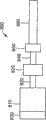
Fig. 1 shows the perspective view of the example embodiment of a system that comprises system according to the invention;
Fig. 2 shows the close-up illustration according to the part of system as shown in Figure 1 of the present invention;
Fig. 3 shows another perspective view according to system as shown in Figure 1 of the present invention;
Fig. 4 shows the schematic diagram according to an example embodiment of casting device of the present invention;
Fig. 5 shows the close-up illustration according to the cross section of casting device as shown in Figure 4 of the present invention;
Fig. 6 shows the schematic diagram according to the example embodiment of roller erecting device of the present invention;
Fig. 7 shows the schematic diagram according to the example embodiment of the erecting device that is used for a pair of pattern roller of the present invention;
Fig. 8 shows the schematic diagram according to the example embodiment of motor of the present invention and roller device;
Fig. 9 shows the schematic diagram according to the example embodiment of the device that is used for the alignment between the control roll of the present invention;
Figure 10 shows the schematic diagram according to the example embodiment of roller control device of the present invention;
Figure 11 shows the block diagram according to the example embodiment of the method and apparatus that is used to control alignment of the present invention.
The specific embodiment
Usually, the invention of present disclosure is a kind of system and method that is used to make two-sided little replicated architecture, and the degree of registration of a side and another side is better than about 100 microns, preferably is better than 50 microns, more preferably less than 25 microns, most preferably less than 5 microns.This system generally includes first pattern assembly and second pattern assembly.Each corresponding assembly all forms little copying pattern on the respective surfaces of the width of cloth material with first and second surfaces.First pattern generating is on the first surface of width of cloth material, and second pattern generating is on the second surface of width of cloth material.
Each pattern assembly all comprises the device that is used to apply coating, pattern formation parts and hardening element.Usually, pattern assembly comprises pattern roller and the supporting structure that is used to keep and drive each roller.The apparatus for coating of first pattern assembly is distributed in the first curable coating material on the first surface of width of cloth material.The apparatus for coating of second pattern assembly is distributed in the second curable coating material on the second surface of width of cloth material, and wherein second surface is relative with first surface.Usually, first and second coating materials have identical composition.
After being placed on first coating material on the width of cloth material, width of cloth material wherein, has produced pattern by first patterned member in first coating material.Then, first coating material is solidified or cooling, thereby form first pattern.Subsequently, after being placed on second coating material on the width of cloth material, width of cloth material wherein, has produced pattern by second patterned member in second coating material.Second coating material solidified, thereby form second pattern thereafter.Usually, each patterned member all is little instrument that duplicates, and each instrument generally all has special-purpose hardening element, with so that material cured.But, can have single hardening element, this single hardening element solidifies first and second patterns and forms material.And, coating can be placed on the described pattern instrument.
Described system also comprises the device that is used to make the rotation of first and second pattern rollers, make their pattern when width of cloth material is in the continuous motion, be transferred on the relative side of this width of cloth material, and described pattern remain on and is better than in about 100 micrometer ranges alignment continuously on the described relative side of width of cloth material.
An advantage of the invention is, by means of the little replicated architecture progressive forming that makes on each side of width of cloth material, little replicated architecture on the opposite flank is alignd in 100 micrometer ranges each other substantially, generally in 50 micrometer ranges, align, more generally in 20 micrometer ranges, align, and the most usually in 5 micrometer ranges, align, can produce the width of cloth material that on each apparent surface of width of cloth material, has little replicated architecture.
Referring now to Fig. 1-2,, there is shown the example embodiment that comprises according to the system 110 of casting device 120 of the present disclosure.Shown in casting device 120 in, provide width of cloth material 122 from main unwinding spool (not shown) to this casting device 120.According to the product of being produced, the definite character of width of cloth material 122 can change widely.But, when casting device 120 was used to make optical article, width of cloth material 122 was translucent or transparent normally easily, solidified by width of cloth material 122 to allow.Width of cloth material 122 is imported in the casting device 120 around each roller 126.
Need implement accurate tension force control to width of cloth material 122, with the optimum efficiency of realizing that the present invention can reach, thereby width of cloth material 122 is directed into the tension sensing device (not shown).Use lined web to protect under the situation of width of cloth material 122 in expectation, this lined web is generally separated on the unwinding spool, and is guided on the lined web winding reel (not shown).The width of cloth material 122 general dance rollers (dancer roller) that are used for accurate tension force control that are guided via idler roller.Idler roller directs into width of cloth material 122 on the position between the nip rolls 154 and first coater head 156.
In the embodiment shown, first coater head 156 is mould coater head (die coating).But, such just as one of ordinary skill in the art will appreciate, other coating process also can be suitable for this device.Then, width of cloth material 122 is by between the nip rolls 154 and first pattern roller 160.First pattern roller 160 has pattern and forms surface 162, and when width of cloth material 122 passed through between the nip rolls 154 and first pattern roller 160, the forming materials that is assigned on the width of cloth material 122 by first coater head 156 was the negative-appearing image that pattern forms surface 162.
When width of cloth material 122 contacted with first pattern roller 160, material was assigned on other surface of width of cloth material 122 from second coater head 164.With top with respect to first coater head 156 discussed identical, second coater head 164 is the mould apparatus for coating also, it comprises the second extruder (not shown) and second coating die head (coating die) (not shown).In certain embodiments, the material that is distributed by first coater head 156 is a synthetic, and this synthetic comprises polymer precursor, and is tending towards being solidified into solid polymer under the effect of ultraviolet radiation.
Then, being assigned to material and second pattern of second pattern roller 174 on the width of cloth material 122 by second coater head 164 forms surface 176 and contacts.Identical with above-mentioned situation, in certain embodiments, the material that is distributed by second coater head 164 also is a synthetic, and this synthetic comprises polymer precursor, and is tending towards being solidified into solid polymer under the effect of ultraviolet radiation.
At this moment, the two sides of width of cloth material 122 has all applied pattern.Can have stripper roll 182, width of cloth material 122 be peeled off from second pattern roller 174 with help.Usually, the tension force of width of cloth material turnover casting device almost is constant.
Then, the width of cloth material 122 that will have a two-sided microreplicated pattern via each idler roller directs to the winding reel (not shown).If expectation is protected width of cloth material 122 with interval film, then it is generally provided by auxiliary unwinding spool (not shown), and width of cloth material and interval film are wound onto on the winding reel under suitable tension force together.
Connect with first and second motor sub-assemblies 210,220 respectively referring to Fig. 1-3, the first and second pattern roller.By directly or indirectly assembly being installed on the frame 230, realized supporting to motor sub-assembly 210,220.Motor sub-assembly 210,220 adopts accurate erecting device and is connected on the frame.Shown in example embodiment in, first motor sub-assembly 210 is fixedly mounted on the frame 230.Second motor sub-assembly 220 needs resetting, and therefore can laterally and on the machine direction move, and wherein when width of cloth material 122 passed through Casting Equipment 120, this motor sub-assembly 220 was placed and puts in place.Active motors assembly 220 preferably is connected on the linear slide block 222, repeatedly accurately locatees with help, when for example changing between the pattern on roller.Second motor sub-assembly 220 also comprises second erecting device 225 that is positioned on frame 230 back sides, and it is used for second pattern roller 174 with respect to first pattern roller, 160 left-to-right location.Second erecting device 225 preferably includes linear slide block 223, and this linear slide block 223 is allowed on the traversed by machine direction accurately location.
Referring to Fig. 6, there is shown motor installation device.Being used for the motor 633 of driven tool or pattern roller 662 is installed on the frame 650, and is connected by shaft coupling 640 on the rotating shaft 601 of pattern roller 662.Motor 633 is connected on the main encoder 630.Secondary encoder 651 is connected on the instrument of controlling in order to the accurate angular alignment that pattern roller 662 is provided.Main encoder 630 and the 651 mutual cooperations of secondary encoder provide the control to pattern roller 662, align with second pattern roller to keep it, as will be described further below.
Shown in example embodiment in, the diameter of tool roll 662 is generally less than the diameter of its motor 633.In order to hold this device, two tool roll assemblies 610,710 are installed into mirror image, so that can allow two tool roll 662,762 as shown in Figure 7 together.Also referring to Fig. 1, first motor apparatus generally is connected on the frame regularly, and second motor apparatus is located by using movable optical quality.
Because axle resonance is that pattern position is controlled at the alignment error source of specifying in the limit value, thereby to reduce or eliminate axle resonance be important.Adopt the bigger shaft coupling 640 than general size plan regulation between motor 633 and axle 650, this also will reduce to be resonated by the axle that the bigger shaft coupling of flexibility causes.On in order to each position that swivel bearing is provided to motor apparatus, all located bearing assembly.
Referring to Fig. 4, there is shown the example embodiment of casting device 420, this casting device 420 is used for producing the two-sided web 422 of the little replicated architecture that has alignment on the apparent surface.Assembly comprises first and second apparatus for coating 456,464, nip rolls 454 and first and second pattern rollers 460,474.Width of cloth material 422 is positioned on first apparatus for coating 456, in this example, is positioned on first extrusion die 456.First extrusion die 456 is assigned to the first curable liquid coating 470 on the width of cloth material 422.By means of nip rolls 454, be generally the roller that rubber covers, first coating 470 is pressed in first pattern roller 460.And on first pattern roller 460, use outside curing source 480, and the lamp of the light of suitable wavelength for example, normally ultraviolet light makes paint solidification.
Adopt the second side extrusion die 464 second curable liquid layer to be coated on the opposite flank of width of cloth material 422.Second coating 481 is pressed in the second pattern tool roll 474, and second coating 481 is repeated solidification process.By tool roll 460,474 being kept accurate each other angular relationship, realized the alignment of two coated patterns, as will be described below.
Referring to Fig. 5, there is shown the close up view of the part of first and second pattern rollers 560,574.First pattern roller 560 has first pattern 562 that forms little replicated surfaces.Second pattern roller 574 has second little copying pattern 576.
Shown in example embodiment in, although pattern can be different, first and second patterns the 562, the 576th, identical pattern.Along with width of cloth material 522 passes through first roller 560, the first curable liquid (not shown) on the first surface 524 solidifies under near 525 effects of the curing light source the first area 526 on first pattern roller 560.After liquid curing, first little copying pattern structure 590 forms on first side 524 of width of cloth material 522.First patterning 590 is negative-appearing images of the pattern 562 on first pattern roller 560.After first patterning 590 forms, second curable liquid 581 is assigned on the second surface 527 of width of cloth material 522.Can not solidify prematurely in order to ensure second liquid 581, second liquid 581 and first be solidified light 525 separate, generally be positioned to make it not impinge upon on second liquid 581 first curing light source 525.Perhaps, can solidify placement screening arrangement 592 between the light 525 and second liquid 581 first.And, curing source can be positioned in its corresponding pattern roller, at this, it is unrealistic or difficult passing the curing of width of cloth material.
After first patterning 590 formed, width of cloth material 522 continued to extend along first roller 560, till it enters gap area 575 between first pattern roller 560 and second pattern roller 574.Then, second liquid 581 engages with second pattern 576 on second pattern roller, and is shaped to second little replicated architecture, and this second little replicated architecture solidifies under the effect of light 535 second and solidifies then.Along with width of cloth material 522 enters in the gap 575 between first pattern roller 560 and second pattern roller 574, substantially first patterning, the 590 restriction width of cloth materials 522 that solidify this moment and be attached on the width of cloth material 522 slide, and width of cloth material 522 begins to move into around gap 575 neutralizations second pattern roller 574 simultaneously.This width of cloth material of having eliminated as the alignment error between first and second patternings that form on the width of cloth material stretches and slides.
By width of cloth material 522 being supported on first pattern roller 560, second liquid 581 is contacted with second pattern roller 574, be formed at the control function that degree of registration between first and second the little replicated architecture 590,593 on the opposite flank 524,527 of width of cloth material 522 becomes the position relation between the surface of first and second pattern roller 560,574.Width of cloth material around first and second pattern roller 560,574 and the volume of the S shape between the gap 575 that forms by these two pattern rollers farthest reduced the influence controlled by the tension effect that mechanism caused of clamping width of cloth material, width of cloth material tension variations, temperature, microslip and lateral attitude.Usually, S shape volume makes coiled material 522 and each roller keep in touch the cornerite that surpasses 180 degree, but cornerite can be according to concrete needs or bigger or littler.
In order to increase the degree of registration between the pattern that forms on the width of cloth material apparent surface, preferably has pitch variation than low frequency around each roller average diameter.Usually, pattern roller has identical average diameter, but this point is optional.At the suitable roller of any concrete application choice in those of ordinary skills' ability and ken.
Be in meticulous alignment scope each other owing to wish the characteristic size that is positioned on two lip-deep little replicated architectures of width of cloth material, thereby need high precision ground control chart table roll.Described in hereinafter,, can realize described here in limited range, striding the alignment of width of cloth material direction by means of adopting the technology that is adopted when the alignment of control machine direction.Need be in the enterprising row alignment control of machine direction, up to now, this does not also realize on two-sided little width of cloth material that duplicates as yet.For example, in order to obtain the feature placement that about 10 microns head and the tail connect on the pattern roller of 10 inches circumference, each roller all must remain on ± the rotation accuracy of 32 second of arc/commentaries on classics in.Along with the pass through speed of system of width of cloth material increases, the control of the alignment difficulty more that becomes.
The applicant has set up and has proved that the system of the pattern roller with 10 inches circumference can be created in the width of cloth material that has pattern characteristics on the apparent surface, and this pattern characteristics aligns in 2.5 micrometer ranges.After reading present disclosure and being used in this principle of instructing, those of ordinary skill in the art will be understood that the degree of registration that how to realize with other little replicated surfaces.
Referring to Fig. 8, there is shown the schematic diagram of motor apparatus used in the applicant system 800.Motor apparatus comprises motor 810, and this motor 810 comprises main encoder 830 and driving shaft 820.Driving shaft 820 connects with the driven shaft 840 of pattern roller 860 by shaft coupling 825.Secondary encoder or load encoder (load encoder) 850 are incorporated on this driven shaft 840.Use two encoders in the described motor apparatus to allow and the position of survey map table roll more exactly, thereby reduce or the influence of the torque disturbance when eliminating motor apparatus 800 and turning round by measurement mechanism (encoder) 850 being positioned near the pattern roller 860.
Referring to Fig. 9, the schematic diagram when there is shown the motor apparatus shown in Fig. 8 and being connected on some control assemblies.In the exemplary device shown in Fig. 1-3, similar mechanism will control each motor apparatus 210 and 220.
Motor apparatus 900 is connected with control device 965, to allow accurately control chart table roll 960.Control device 965 comprises driver module 966 and program module 975.Program module 975 is via circuit 977, for example SERCOS fiber optic network and be connected with driver module 966.Program module 975 is used for to a plurality of parameters of driver module 966 inputs, such as setting value.Driver module 966 receives 3 phase power supplys 915 of 480 volts of input voltages, and it is rectified into direct current, distributes direct current via electric power connection 973 then, in order to control motor 910.Motor encoder 912 is fed to driver module 966 with position signalling.Secondary encoder 950 on the pattern roller 960 also feeds back to driver module 966 via circuit 971 with position signalling.Driver module 966 uses code device signal to come accurately network for location table roll 960.To describe in detail this below in order to realize the control design of degree of registration.
Shown in example embodiment in, each pattern roller is controlled by dedicated control device.A plurality of dedicated control devices first and second pattern of control of cooperating mutually forms alignment between roller.Each driver module all is connected with corresponding motor sub-assembly and this motor sub-assembly is controlled.
Various selection schemes can be used to make diaxon to coordinate mutually, the master/slave type and the parallel-connection structure that use in the system as the applicant.
Control device in the system of applicant's foundation and confirmation comprises following parts.In order to drive each pattern roller, used and had high-resolution sinusoidal coder feedback (512 sinusoidal period * 4096 drive interpolation much larger than 200 very much/change) high-performance, the motor of low change torque, this motor can obtain from Bosch-Rexroth (Indramat), and its model is MHD090B-035-NG0-UN.This system also comprises syncmotor, and it can obtain from Bosch-Rexroth (Indramat), and model is MHD090B-035-NG0-UN, but also can use other type of motor as induction motor.Each motor all passes through extremely hard bellows coupling and directly connects (not having gear-box or mechanical reduction gear (mechanicalreduction)), and this shaft coupling can obtain from R/W company, and model is BK5-300.Can adopt substituting connection design, but bellows generally can provide high rotation accuracy and hardness simultaneously.The size of each shaft coupling all is shaped such that selects the basic bigger shaft coupling of recommending than general manufacturer specification of shaft coupling.In addition, zero clearance engine base sleeve or compression-type locking axle center preferably between shaft coupling and axle.Each roll shaft is all by can being that the hollow shaft load side encoder of RON255C is connected on the encoder from continue model that the Heidenhain company of nurse fort obtains of Illinois, USA.The selection of encoder should have the highest accuracy and possible resolution ratio, general accuracy greater than 32 second of arcs.18000 sinusoidal period/commentaries on classics have been adopted in applicant's design, and it drives interpolation with 4096 bit resolutions and combines, and produce to exceed 5,000 ten thousand fens/resolution ratio of changeing, and make resolution ratio than accuracy height.The load end encoder has+accuracy of/-2 second of arcs; The maximum deviation of unit of transfer is less than+/-1 second of arc.
Preferably, it is big as much as possible that each axle is designed to diameter, and short as much as possible, so that hardness reaches maximum, thereby produces high as far as possible resonant frequency.The accurate aligning of wishing all rotary parts can be guaranteed to reach minimum by this caused alignment error in alignment error source.Those of ordinary skill in the art will recognize, have several different methods to reduce the alignment error that the alignment because of rotary components causes.
Each control strategy is implemented as follows:
Referring to Figure 11, in applicant's system, identical position coordinates order offers each axle by the SERCOS fiber optic network simultaneously with 2 milliseconds renewal speed.Each all utilize cubic spline with 250 microseconds position loop renewal speed at interval to this position coordinates interpolation.Interpolation method is not crucial, and this is because the time interval path that constant speed produces single constant multiple.Resolution ratio is for eliminating any round off or the numeric representation error is crucial.Also must handle the axle upset.Key is to make the control cycle of each synchronous down in current loop execution speed (intervals of 62 microseconds).
Deduct position command 1111 from current location 1114, thereby produce error signal 1116.This error signal 1116 is applied on the proportional controller 1115, thereby produces speed command coordinate 1117.From this speed command 1117, deduct speed feedback 1167, thereby produce speed error signal 1123, then this speed error signal 1123 is applied on the PID controller.Speed feedback 1167 is by means of motor encoder position signalling 1126 being carried out differential and producing.Because the differential and the numerical value limit of resolution have been used low pass Pasteur (Butterworth) wave filter 1124, in order to eliminate the high frequency noise composition in the error signal 1123.In the center applications of motor-roller resonant frequency arrowband resistance (line trap) wave filter 1129.This permission has applied higher substantially gain to speed control 1120.The increase of motor encoder resolution ratio also will improve performance.The exact position of wave filter in control chart is not key point; Depend on the position although regulate parameter, forward path or backward channel all are acceptables.
The PID controller also can be used in the position loop, but the additional phase lag of integrator makes and stable becomes more difficult.Current loop is traditional PI controller; Gain is set up by parameters of hydraulic motor.The current loop that bandwidth is high as far as possible will make performance the best.And, the pulsation minimum of wishing torque.
External interference minimize that alignment is important for obtaining farthest.This comprises motor structure previously discussed and current loop rectification, also is important but machinery is disturbed reach minimum.Tension force control extremely stably, supporting uniformly and hermetic resistance when example is included in turnover width of cloth material span, make the tension force disturbance of peeling off width of cloth material from roller reach minimum and rubber nip rolls uniformly.In current design, be provided with the 3rd that meshes with tool roll, as the pulling roller, to help to take off the structure of curing from instrument.
Width of cloth material material can be any suitable material that can produce little copying pattern structure in the above.Width of cloth material examples of material is PETG, polymethyl methacrylate or Merlon.Width of cloth material also can be a multilayer.Because liquid generally solidifies under the effect that is positioned at the curing source on the opposite flank that produces patterning, thereby width of cloth material material must be translucent at least in part for employed curing source.What solidify energy source is exemplified as infrared radiation, ultraviolet radiation, visible radiation, microwave or electron beam.Those of ordinary skill in the art will be understood that, can adopt other curing source, and the selection of concrete width of cloth material material/curing source combination will be depended on the special article (having the little replicated architecture that is in alignment) that will produce.
The alternative that is used to solidify the liquid by width of cloth material is to adopt two-part reaction to solidify, epoxy resin for example, and the width of cloth material that reaction is solidified being difficult to solidify is useful, such as metal width of cloth material or have the width of cloth material of metal level.By fractions on the part of on-line mixing pattern roller or spraying catalyst, can realize solidifying, when coating contacts with catalyst, it will make liquid curing, thereby form little replicated architecture.
The liquid that produces little replicated architecture generally is curable photopolymerization material, such as the acrylate that can solidify under the UV light action.Those of ordinary skill in the art will be understood that, can adopt other coating material, and the selection of for example polymerizable material, and material will be depended on the characteristic that little replicated architecture is desired.Similarly, in the concrete curing one skilled in the relevant art's who is adopted the ability and ken.The example of curing is reaction curing, heat cure or radiation curing.
To the example that liquid is transported on the width of cloth material and control useful apparatus for coating be: for example mould coating or the scraper coating that combines with any suitable pump as syringe pump or peristaltic pump.Those of ordinary skill in the art will be understood that, can adopt other apparatus for coating, and the selection of concrete device will be depended on the concrete property that will be transported to the liquid on the width of cloth material.
Various modification of the present invention and replacement will be conspicuous for a person skilled in the art, and can not depart from the scope of the present invention and marrow, and it should be understood that the present invention is not limited to illustrative embodiment described herein.
Claims (22)
1, a kind of device that is used for patterned surfaces on the direct casting of the two sides of width of cloth material, this device comprises:
First pattern roller;
Second pattern roller;
Be used to make the device of this first and second pattern rollers rotation, make the pattern of described two pattern rollers when width of cloth material is in continuous motion, be transferred on the relative side of this width of cloth material, and
Thereby being communicated with the device that is used to make this first and second pattern rollers rotation and this device controlled makes this pattern remain on the control device that aligns continuously in 100 micrometer ranges on the opposite flank of described width of cloth material.
2, device as claimed in claim 1 wherein, is transferred on the opposite flank of width of cloth material under the degree of registration of described pattern in 50 micrometer ranges.
3, device as claimed in claim 2 wherein, is transferred on the opposite flank of width of cloth material under the degree of registration of described pattern in 20 micrometer ranges.
4, device as claimed in claim 3 wherein, is transferred on the opposite flank of width of cloth material under the degree of registration of described pattern in 5 micrometer ranges.
5, device as claimed in claim 1, this device also comprises: first distributor, the material that is used for can forming pattern before width of cloth material and first pattern roller meet is directed to this width of cloth material; And this device also comprises second distributor, and the material that is used for can forming pattern before this width of cloth material and second pattern roller meet is directed to this width of cloth material.
6, device as claimed in claim 1, this device also comprises: first distributor, the material that is used for forming pattern is directed on first pattern roller; And this device also comprises second distributor, and the material that is used for forming pattern is directed on second pattern roller.
7, device as claimed in claim 5, wherein, described first and second distributors are suitable for distributing and can be solidified into polymer precursor solid polymer, the energy mold.
8, device as claimed in claim 7, this device comprise that also the material that is used to make contiguous first and second pattern rollers is exposed to the device under the heat.
9, device as claimed in claim 7, this device comprise that also the material that is used for making contiguous first and second pattern rollers is exposed to the device of radiant energy.
10, device as claimed in claim 9, wherein, the described device that is used for making the material of contiguous first pattern roller to be exposed to radiant energy is set in this first pattern roller, and this first pattern roller has at least one and can allow the permeable part of radiation basically.
11, device as claimed in claim 10, wherein, described radiant energy is selected from the group that is made of infrared radiation, visible radiation and ultraviolet radiation.
12, a kind of being used for applies method of patterning on the two sides of width of cloth material, may further comprise the steps:
Make width of cloth material between first and second pattern rollers, form pattern, each roller all has pattern, make by utilizing dedicated control device that each pattern roller is controlled, thereby make these patterns when width of cloth material is in continuous motion, be transferred on the opposite flank of this width of cloth material, wherein, this dedicated control device is cooperated mutually, and to control the alignment between this first and second pattern roller, all its corresponding motor sub-assembly of each driver module is connected and this motor sub-assembly is controlled.
13, method as claimed in claim 12 wherein, is transferred on the opposite flank of width of cloth material under the degree of registration of described pattern in 50 micrometer ranges.
14, method as claimed in claim 13 wherein, is transferred on the opposite flank of width of cloth material under the degree of registration of described pattern in 20 micrometer ranges.
15, method as claimed in claim 14 wherein, is transferred on the opposite flank of width of cloth material under the degree of registration of described pattern in 5 micrometer ranges.
16, method as claimed in claim 12, this method is further comprising the steps of:
Before width of cloth material and first pattern roller met, the material that can form pattern was directed on the side of this width of cloth material;
Before width of cloth material and second pattern roller met, the material that can form pattern was directed on another opposite flank of this width of cloth material.
17, method as claimed in claim 12, this method is further comprising the steps of:
The material that can form pattern is directed on first pattern roller; And
The material that can form pattern is directed on second pattern roller.
18, method as claimed in claim 16, wherein, described at least a material is to be solidified into polymer precursor solid polymer, the energy mold.
19, method as claimed in claim 18, this method also comprise make at least a material its with first and second pattern rollers one of them contacts at least the time be exposed to step under the heat.
20, method as claimed in claim 18, also comprise make at least a material its with first and second pattern rollers one of them contacts at least the time be exposed to step in the radiant energy.
21, method as claimed in claim 20, wherein, carry out described exposing step by means of the energy source in one of them at least that is arranged on first and second pattern rollers, and described first and second pattern rollers one of them has at least one and can allow the permeable part of radiation at least.
22, method as claimed in claim 21, wherein, described radiant energy is selected from the group that is made of infrared radiation, visible radiation and ultraviolet radiation.
Applications Claiming Priority (2)
| Application Number | Priority Date | Filing Date | Title |
|---|---|---|---|
| US10/657,859 US7165959B2 (en) | 2003-09-09 | 2003-09-09 | Apparatus and method for producing two-sided patterned webs in registration |
| US10/657,859 | 2003-09-09 |
Publications (2)
| Publication Number | Publication Date |
|---|---|
| CN1867444A CN1867444A (en) | 2006-11-22 |
| CN100556666C true CN100556666C (en) | 2009-11-04 |
Family
ID=34226655
Family Applications (1)
| Application Number | Title | Priority Date | Filing Date |
|---|---|---|---|
| CNB2004800301662A Expired - Fee Related CN100556666C (en) | 2003-09-09 | 2004-07-20 | Be used to make the apparatus and method of the two-sided patterned width of cloth material of alignment |
Country Status (8)
| Country | Link |
|---|---|
| US (2) | US7165959B2 (en) |
| EP (1) | EP1663618B1 (en) |
| JP (1) | JP4653094B2 (en) |
| KR (1) | KR101121811B1 (en) |
| CN (1) | CN100556666C (en) |
| BR (1) | BRPI0414234B1 (en) |
| MX (1) | MXPA06002714A (en) |
| WO (1) | WO2005025837A1 (en) |
Families Citing this family (47)
| Publication number | Priority date | Publication date | Assignee | Title |
|---|---|---|---|---|
| DE10161744A1 (en) * | 2001-12-15 | 2003-06-18 | Werner Jahn | Cling type plastic fastener strip manufacture involves pin creation by compression of plastic strip into holes in a rubber cover on a metal roll then shaping of heads on pins |
| US20040234724A1 (en) * | 2003-05-22 | 2004-11-25 | Eastman Kodak Company | Immisible polymer filled optical elements |
| US7165959B2 (en) * | 2003-09-09 | 2007-01-23 | 3M Innovative Properties Company | Apparatus and method for producing two-sided patterned webs in registration |
| US7224529B2 (en) * | 2003-09-09 | 2007-05-29 | 3M Innovative Properties Company | Microreplicated article |
| US7804649B2 (en) * | 2003-09-09 | 2010-09-28 | 3M Innovative Properties Company | Microreplicated achromatic lens |
| US20050231809A1 (en) * | 2003-09-09 | 2005-10-20 | Carlson Daniel H | Microreplicated polarizing article |
| JP2006165371A (en) * | 2004-12-09 | 2006-06-22 | Canon Inc | Transfer apparatus and device manufacturing method |
| BRPI0608406A2 (en) * | 2005-03-09 | 2009-12-29 | 3M Innovative Properties Co | set, apparatus, method for placing pattern on a continuous opaque sheet and pattern roller |
| JP2008536161A (en) * | 2005-03-09 | 2008-09-04 | スリーエム イノベイティブ プロパティズ カンパニー | Microreplicated articles with moiré reducing surfaces |
| EP1856566A1 (en) * | 2005-03-09 | 2007-11-21 | 3M Innovative Properties Company | Microreplicated article with defect-reducing surface |
| CN101137449B (en) * | 2005-03-09 | 2012-08-29 | 3M创新有限公司 | Microreplicated article and production method thereof |
| EP1874524B1 (en) * | 2005-03-09 | 2009-03-11 | 3M Innovative Properties Company | Apparatus and method for making microreplicated article |
| ATE496706T1 (en) * | 2005-03-09 | 2011-02-15 | 3M Innovative Properties Co | APPARATUS AND METHOD FOR PRODUCING A MICRREPLICATED OBJECT |
| US7830368B2 (en) | 2006-06-06 | 2010-11-09 | 3M Innovative Properties Company | Keypad with virtual image |
| WO2008042348A1 (en) * | 2006-10-02 | 2008-04-10 | Travel Tags, Inc. | Layered image display sheet |
| US8056929B2 (en) * | 2006-10-02 | 2011-11-15 | Travel Tags, Inc. | Layered image display applications and methods |
| US8339444B2 (en) * | 2007-04-09 | 2012-12-25 | 3M Innovative Properties Company | Autostereoscopic liquid crystal display apparatus |
| US7530721B2 (en) | 2007-04-18 | 2009-05-12 | Skc Haas Display Films Co., Ltd. | Double-sided turning film |
| EP3260893A3 (en) | 2007-11-27 | 2018-04-11 | 3M Innovative Properties Co. | Methods for forming sheeting with a composite image that floats and a master tooling |
| US8068187B2 (en) * | 2008-06-18 | 2011-11-29 | 3M Innovative Properties Company | Stereoscopic 3D liquid crystal display apparatus having a double sided prism film comprising cylindrical lenses and non-contiguous prisms |
| KR20110041507A (en) | 2008-07-10 | 2011-04-21 | 쓰리엠 이노베이티브 프로퍼티즈 컴파니 | Viscoelastic lightguide |
| US9285531B2 (en) * | 2008-08-08 | 2016-03-15 | 3M Innovative Properties Company | Lightguide having a viscoelastic layer for managing light |
| CA2735897C (en) | 2008-09-18 | 2015-08-04 | Taylor Corporation | Thin film high definition dimensional image display device and methods of making same |
| US8964297B2 (en) | 2008-09-18 | 2015-02-24 | Travel Tags, Inc. | Thin film high definition dimensional image display device and methods of making same |
| DE102008058458A1 (en) * | 2008-11-21 | 2010-05-27 | Robert Bosch Gmbh | Axis correction method for a processing machine and a processing machine |
| US8339573B2 (en) * | 2009-05-27 | 2012-12-25 | 3M Innovative Properties Company | Method and apparatus for photoimaging a substrate |
| US8659830B2 (en) | 2009-12-21 | 2014-02-25 | 3M Innovative Properties Company | Optical films enabling autostereoscopy |
| US8917447B2 (en) * | 2010-01-13 | 2014-12-23 | 3M Innovative Properties Company | Microreplicated film for attachment to autostereoscopic display components |
| US9146342B2 (en) | 2010-01-13 | 2015-09-29 | 3M Innovative Properties Company | Illumination device having viscoelastic lightguide |
| WO2011100277A1 (en) | 2010-02-10 | 2011-08-18 | 3M Innovative Properties Company | Illumination device having viscoelastic layer |
| US8538224B2 (en) | 2010-04-22 | 2013-09-17 | 3M Innovative Properties Company | OLED light extraction films having internal nanostructures and external microstructures |
| EP2426243A1 (en) * | 2010-09-01 | 2012-03-07 | Benninger Zell GmbH | Method and device for processing (softening) continuously transported goods |
| US8469551B2 (en) | 2010-10-20 | 2013-06-25 | 3M Innovative Properties Company | Light extraction films for increasing pixelated OLED output with reduced blur |
| US8547015B2 (en) | 2010-10-20 | 2013-10-01 | 3M Innovative Properties Company | Light extraction films for organic light emitting devices (OLEDs) |
| JP6105214B2 (en) * | 2012-06-07 | 2017-03-29 | 旭化成株式会社 | Method for producing substrate having fine concavo-convex structure on surface |
| US8915002B2 (en) | 2013-01-31 | 2014-12-23 | 3M Innovative Properties Company | Self illuminated signage for printed graphics |
| US9261641B2 (en) | 2013-03-25 | 2016-02-16 | 3M Innovative Properties Company | Dual-sided film with compound prisms |
| US9784902B2 (en) | 2013-03-25 | 2017-10-10 | 3M Innovative Properties Company | Dual-sided film with split light spreading structures |
| US9082326B2 (en) | 2013-05-02 | 2015-07-14 | 3M Innovative Properties Company | Self illuminated shaped and two-sided signage for printed graphics |
| BR112016006705A2 (en) | 2013-09-27 | 2017-08-01 | 3M Innovative Properties Co | double sided structured film articles |
| US9070312B2 (en) | 2013-11-05 | 2015-06-30 | 3M Innovative Properties Company | Hybrid self illuminated and actively back lit signage for printed graphics |
| CN107533286B (en) | 2015-04-29 | 2022-02-08 | 3M创新有限公司 | Swellable film-forming composition and method for nanoimprint lithography using the same |
| JP6174775B1 (en) * | 2016-03-31 | 2017-08-02 | 東芝機械株式会社 | Sheet / film forming roll apparatus, sheet / film forming method |
| US11633905B2 (en) * | 2016-06-15 | 2023-04-25 | Flooring Industries Limited, Sarl | Long decorative material with embossing in register with pattern and rolling method and device therefor |
| US11633904B2 (en) * | 2016-06-15 | 2023-04-25 | Flooring Industries Limited, Sarl | Long plastic layer with embossing in register with pattern and rolling method and device therefor |
| KR20190023095A (en) | 2016-06-29 | 2019-03-07 | 쓰리엠 이노베이티브 프로퍼티즈 캄파니 | Polymerizable ionic liquid composition |
| JP6311054B1 (en) * | 2017-07-20 | 2018-04-11 | 東芝機械株式会社 | Double-sided transfer type sheet / film forming roll device, Double-sided transfer type sheet / film forming method |
Family Cites Families (109)
| Publication number | Priority date | Publication date | Assignee | Title |
|---|---|---|---|---|
| US1234567A (en) * | 1915-09-14 | 1917-07-24 | Edward J Quigley | Soft collar. |
| US3154730A (en) * | 1961-03-14 | 1964-10-27 | Ibm | Speed control of a d. c. motor |
| US3241429A (en) | 1962-05-14 | 1966-03-22 | Pid Corp | Pictorial parallax panoramagram units |
| US3374303A (en) | 1964-02-14 | 1968-03-19 | Crown Zellerbach Corp | Method for manufacturing imprinted plastic film |
| US3551544A (en) | 1965-12-06 | 1970-12-29 | Tenex Corp | Method of continuously forming an elongated cleated runner of plastic material |
| US3893795A (en) * | 1970-08-20 | 1975-07-08 | Rowland Dev Corp | Embossing rolls with areas of differential hardness |
| US3917772A (en) | 1972-02-10 | 1975-11-04 | Grace W R & Co | Method for producing battery separator sheet |
| DE2344691C3 (en) * | 1973-09-05 | 1981-10-22 | Knorr-Bremse GmbH, 8000 München | Mechanical release device for a spring brake cylinder, in particular for rail vehicle compressed air brake systems |
| US4072403A (en) * | 1975-07-16 | 1978-02-07 | Ludwig Eigenmann | Retro-reflecting assembly |
| US4177304A (en) | 1977-03-17 | 1979-12-04 | Beloit Corporation | Method of coating both sides of a travelling web |
| US6630970B2 (en) * | 2001-07-02 | 2003-10-07 | 3M Innovative Properties Company | Polarizers for use with liquid crystal displays |
| US4219767A (en) * | 1979-03-29 | 1980-08-26 | Tektronix, Inc. | System and method of minimizing velocity fluctuations in a synchronous motor shaft |
| US4249878A (en) * | 1979-05-10 | 1981-02-10 | K. R. Komarek, Inc. | Briquetting press |
| US4280978A (en) * | 1979-05-23 | 1981-07-28 | Monsanto Company | Process of embossing and perforating thermoplastic film |
| US4414316A (en) | 1980-09-05 | 1983-11-08 | Rexham Corporation | Composite lenticular screen sheet |
| US4420502A (en) | 1980-09-05 | 1983-12-13 | Conley Kenneth E | Apparatus and method for producing a flexible sheet material having a predetermined surface characteristic |
| DE3279203D1 (en) * | 1981-03-16 | 1988-12-15 | Heinz Georg Baus | Method for producing multi-layered plates |
| DE3206164C2 (en) * | 1981-03-16 | 1985-02-21 | Heinz Georg Hünibach Thun Baus | Device for the production of multi-layer panels |
| EP0158085B1 (en) | 1984-03-08 | 1989-01-18 | Altura Leiden Holding B.V. | Apparatus for manufacturing sheets, and sheets manufactured by this apparatus |
| US4744936A (en) * | 1986-01-30 | 1988-05-17 | Plastic Film Corporation Of America | Process for embossing thermoplastic material |
| DE3609090A1 (en) * | 1986-03-18 | 1987-09-24 | Gao Ges Automation Org | SECURITY PAPER WITH SECURED THREAD STORED IN IT AND METHOD FOR THE PRODUCTION THEREOF |
| US4836874A (en) | 1987-01-30 | 1989-06-06 | Foster Michael S | Method of mass producing damage-resistant compact discs |
| US5164227A (en) * | 1987-06-19 | 1992-11-17 | Van Leer Metallized Products (Usa) Limited | Method for embossing a coated sheet with a diffraction or holographic pattern |
| US5028361A (en) * | 1987-11-09 | 1991-07-02 | Takeo Fujimoto | Method for molding a photosensitive composition |
| JP2692095B2 (en) | 1987-12-16 | 1997-12-17 | ソニー株式会社 | Screen manufacturing method |
| DE4001105C1 (en) * | 1990-01-17 | 1991-08-08 | Hermann Berstorff Maschinenbau Gmbh, 3000 Hannover, De | |
| US6724536B2 (en) * | 1990-05-18 | 2004-04-20 | University Of Arkansas | Directional image lenticular window sheet |
| US5177637A (en) * | 1990-09-11 | 1993-01-05 | Nikon Corporation | Focusing screen including different height microlenses arranged in a cyclical pattern |
| JP3158476B2 (en) | 1991-03-28 | 2001-04-23 | 凸版印刷株式会社 | Method for manufacturing double-sided lenticular sheet |
| JPH0580530A (en) * | 1991-09-24 | 1993-04-02 | Hitachi Ltd | Production of thin film pattern |
| EP0534471A1 (en) * | 1991-09-27 | 1993-03-31 | Toppan Printing Co., Ltd. | Composite laminate and method for the manufacture thereof |
| WO1993023244A1 (en) | 1992-05-08 | 1993-11-25 | Raymond Enterprises, Inc. | Lenticular optical system |
| JP2756211B2 (en) * | 1992-06-17 | 1998-05-25 | ワイケイケイ株式会社 | Method and apparatus for manufacturing integrally molded surface fastener having engagement pieces on both sides |
| US5301981A (en) | 1992-07-09 | 1994-04-12 | Docusafe, Ltd. | Copy preventing device and method |
| DE4226906A1 (en) * | 1992-08-14 | 1994-02-17 | Basf Magnetics Gmbh | Anti-copy film or layer for documents |
| US5330799A (en) * | 1992-09-15 | 1994-07-19 | The Phscologram Venture, Inc. | Press polymerization of lenticular images |
| US5448401A (en) * | 1992-12-25 | 1995-09-05 | Sony Corporation | Screen of projection display |
| KR0168879B1 (en) * | 1992-12-25 | 1999-04-15 | 기따지마 요시또시 | Renticular lens, surface light source and liquid crystal display apparatus |
| US5333072A (en) * | 1992-12-31 | 1994-07-26 | Minnesota Mining And Manufacturing Company | Reflective liquid crystal display overhead projection system using a reflective linear polarizer and a fresnel lens |
| DE69405451T2 (en) * | 1993-03-16 | 1998-03-12 | Koninkl Philips Electronics Nv | Method and device for producing a structured relief image from cross-linked photoresist on a flat substrate surface |
| US5691846A (en) | 1993-10-20 | 1997-11-25 | Minnesota Mining And Manufacturing Company | Ultra-flexible retroreflective cube corner composite sheetings and methods of manufacture |
| US5579164A (en) * | 1993-11-12 | 1996-11-26 | Pharos Technology Corporation | Spatially multiplexed image display system |
| US6025897A (en) * | 1993-12-21 | 2000-02-15 | 3M Innovative Properties Co. | Display with reflective polarizer and randomizing cavity |
| US5759455A (en) * | 1994-07-08 | 1998-06-02 | Canon Kabushiki Kaisha | Roller-shaped stamper for fabricating optical scales |
| US5540147A (en) * | 1994-12-02 | 1996-07-30 | Corning Incorporated | Method for forming a contoured planarizing layer for a color filter |
| EP0741143B1 (en) * | 1995-04-25 | 2005-07-06 | Ajinomoto Co., Inc. | Fibroblast growth factor fragments |
| EP0871923A1 (en) * | 1995-06-26 | 1998-10-21 | Minnesota Mining And Manufacturing Company | Transflective displays with reflective polarizing transflector |
| US6130777A (en) * | 1996-05-16 | 2000-10-10 | Dai Nippon Printing Co., Ltd. | Lenticular lens sheet with both a base sheet having lenticular elements and a surface diffusing part having elements of elementary shape smaller than lenticular elements |
| US5800723A (en) * | 1996-12-10 | 1998-09-01 | Motorola, Inc. | Process for fabricating flex circuits and product thereby |
| US6197397B1 (en) * | 1996-12-31 | 2001-03-06 | 3M Innovative Properties Company | Adhesives having a microreplicated topography and methods of making and using same |
| JPH10211650A (en) * | 1997-01-31 | 1998-08-11 | Asahi Chem Ind Co Ltd | Synthetic resin sheet molding roll equipment |
| JP3665836B2 (en) * | 1997-02-05 | 2005-06-29 | 大日本印刷株式会社 | Film screen manufacturing apparatus and manufacturing method |
| US5922238A (en) * | 1997-02-14 | 1999-07-13 | Physical Optics Corporation | Method of making replicas and compositions for use therewith |
| US6280063B1 (en) * | 1997-05-09 | 2001-08-28 | 3M Innovative Properties Company | Brightness enhancement article |
| DE19721170A1 (en) | 1997-05-21 | 1998-11-26 | Emtec Magnetics Gmbh | Method and device for producing a film or a layer with a surface structure on both sides |
| US6577358B1 (en) * | 1997-06-25 | 2003-06-10 | Dai Nippon Printing Co., Ltd. | Lens film with conductive lens layer or conductive layer |
| KR100485218B1 (en) | 1997-06-30 | 2005-08-10 | 주식회사 엘지화학 | Projection TV Screen |
| JP3685433B2 (en) * | 1997-09-09 | 2005-08-17 | 大日本印刷株式会社 | Film screen manufacturing apparatus and manufacturing method |
| US6074192A (en) * | 1997-09-11 | 2000-06-13 | Mikkelsen; Oeystein | Lenticular pattern forming roll and method for making the roll |
| CN100409043C (en) * | 1997-12-16 | 2008-08-06 | “尼奥匹克”俄罗斯联邦全国科技中心 | Polaroid and liquid crystal display element |
| US6024455A (en) * | 1998-01-13 | 2000-02-15 | 3M Innovative Properties Company | Reflective article with concealed retroreflective pattern |
| US6183671B1 (en) * | 1998-01-30 | 2001-02-06 | Springs Window Fashions Division, Inc. | Apparatus and method for embossing and printing elongated substrates |
| CA2318790C (en) * | 1998-02-18 | 2004-03-30 | Minnesota Mining And Manufacturing Company | Optical film |
| US6628460B1 (en) * | 1998-08-05 | 2003-09-30 | Mitsubishi Rayon Co., Ltd. | Lens sheet and method for producing the same |
| US6149849A (en) * | 1998-08-14 | 2000-11-21 | The Procter & Gamble Copmany | Process and apparatus for making papermaking belt |
| US6187250B1 (en) * | 1998-08-19 | 2001-02-13 | James Champagne | Continuous gel casting method and apparatus |
| US6266476B1 (en) * | 1998-08-25 | 2001-07-24 | Physical Optics Corporation | Optical element having an integral surface diffuser |
| JP3542329B2 (en) * | 1998-09-16 | 2004-07-14 | 富士通株式会社 | Optical device and display device using the same |
| JP2000275406A (en) * | 1999-03-29 | 2000-10-06 | Dainippon Printing Co Ltd | Lens sheet and its manufacture |
| US6272275B1 (en) * | 1999-06-25 | 2001-08-07 | Corning Incorporated | Print-molding for process for planar waveguides |
| BR0007172A (en) * | 1999-09-30 | 2001-09-04 | Koninkl Philips Electronics Nv | Lenticular device, and, set of lenticular devices |
| DE60007535T2 (en) * | 1999-10-08 | 2004-11-11 | Sumitomo Bakelite Co. Ltd. | METHOD AND DEVICE FOR PRODUCING A POLYMER FILM |
| US6368682B1 (en) * | 1999-10-22 | 2002-04-09 | 3M Innovative Properties Company | Composition and structures made therefrom |
| US6908295B2 (en) * | 2000-06-16 | 2005-06-21 | Avery Dennison Corporation | Process and apparatus for embossing precise microstructures and embossing tool for making same |
| US6373636B1 (en) * | 2000-09-08 | 2002-04-16 | Kenneth E. Conley | Heat stabilized and dimensionally stable thin lenticular film |
| JP2002090889A (en) * | 2000-09-14 | 2002-03-27 | Kuraray Co Ltd | Rear projection screen and its manufacture |
| JP2002113728A (en) * | 2000-10-06 | 2002-04-16 | Mitsubishi Rayon Co Ltd | Method for manufacturing lens sheet |
| JP2002210915A (en) * | 2001-01-22 | 2002-07-31 | Tokyo Kikai Seisakusho Ltd | Multi-color printing lithographic printing press which drives split plate cylinder individually |
| KR100870800B1 (en) * | 2001-02-07 | 2008-11-27 | 코닝 인코포레이티드 | Self-aligned aperture masks having high definition apertures |
| ITPS20010006A1 (en) * | 2001-02-23 | 2002-08-23 | Canti & Figli Srl | PROCEDURE AND MACHINE FOR OBTAINING EMBOSSING ON PAINTED SURFACES OF PANELS OR COATING FILMS AND OBTAINED ELEMENTS |
| DE60233838D1 (en) * | 2001-04-03 | 2009-11-12 | Sharp Kk | Developing device, method of charging applied thereto, and printing apparatus with the developing device |
| DE60228943D1 (en) * | 2001-04-10 | 2008-10-30 | Harvard College | MICROLINS FOR PROJECTION SLITHOGRAPHY AND ITS PRODUCTION PROCESS |
| DE60200225T2 (en) * | 2001-04-20 | 2004-07-15 | Matsushita Electric Industrial Co., Ltd., Kadoma | Microlens array and method for its manufacture |
| US7420005B2 (en) * | 2001-06-28 | 2008-09-02 | Dai Nippon Printing Co., Ltd. | Photocurable resin composition, finely embossed pattern-forming sheet, finely embossed transfer sheet, optical article, stamper and method of forming finely embossed pattern |
| US6863107B2 (en) * | 2001-10-02 | 2005-03-08 | Sca Hygiene Products Gmbh | Device for applying a spot embossing pattern to a web of multi-ply tissue paper |
| US6881471B2 (en) * | 2001-10-25 | 2005-04-19 | The Procter & Gamble Company | High speed embossing and adhesive printing process and apparatus |
| US6717749B2 (en) * | 2001-11-01 | 2004-04-06 | Pentax Corporation | Cemented lens group |
| US20030108710A1 (en) * | 2001-12-07 | 2003-06-12 | General Electric Company | Articles bearing patterned microstructures and method of making |
| KR20040111413A (en) * | 2002-03-15 | 2004-12-31 | 더 프록터 앤드 갬블 캄파니 | Elements for embossing and adhesive application |
| AT502319B1 (en) | 2002-04-11 | 2009-11-15 | Hueck Folien Gmbh | SUBSTRATES WITH PREFERABLY TRANSFERABLE LAYERS AND / OR SURFACE STRUCTURES, METHOD FOR THEIR PRODUCTION AND THEIR USE |
| US7140812B2 (en) * | 2002-05-29 | 2006-11-28 | 3M Innovative Properties Company | Diamond tool with a multi-tipped diamond |
| DE10242441A1 (en) * | 2002-09-11 | 2004-04-01 | Erco Leuchten Gmbh | lamp |
| US6963184B2 (en) * | 2002-09-26 | 2005-11-08 | 3M Innovative Properties Company | Adaptable spatial notch filter |
| JP4023294B2 (en) * | 2002-11-11 | 2007-12-19 | 凸版印刷株式会社 | Method for manufacturing lenticular lens sheet |
| US7186004B2 (en) * | 2002-12-31 | 2007-03-06 | Karlton David Powell | Homogenizing optical sheet, method of manufacture, and illumination system |
| CN100429067C (en) * | 2003-05-23 | 2008-10-29 | 大日本印刷株式会社 | Optical sheet and its manufacturing method |
| US20050008821A1 (en) * | 2003-07-07 | 2005-01-13 | Pricone Robert M. | Process and apparatus for fabricating precise microstructures and polymeric molds for making same |
| US7165959B2 (en) * | 2003-09-09 | 2007-01-23 | 3M Innovative Properties Company | Apparatus and method for producing two-sided patterned webs in registration |
| US20050231809A1 (en) * | 2003-09-09 | 2005-10-20 | Carlson Daniel H | Microreplicated polarizing article |
| US7804649B2 (en) * | 2003-09-09 | 2010-09-28 | 3M Innovative Properties Company | Microreplicated achromatic lens |
| US7224529B2 (en) * | 2003-09-09 | 2007-05-29 | 3M Innovative Properties Company | Microreplicated article |
| US7106517B2 (en) * | 2003-12-31 | 2006-09-12 | General Electric Company | Display optical films |
| US7808706B2 (en) * | 2004-02-12 | 2010-10-05 | Tredegar Newco, Inc. | Light management films for displays |
| US20050224997A1 (en) * | 2004-04-08 | 2005-10-13 | Tsung-Neng Liao | Method of fabricating optical substrate |
| BRPI0608406A2 (en) * | 2005-03-09 | 2009-12-29 | 3M Innovative Properties Co | set, apparatus, method for placing pattern on a continuous opaque sheet and pattern roller |
| EP1874524B1 (en) * | 2005-03-09 | 2009-03-11 | 3M Innovative Properties Company | Apparatus and method for making microreplicated article |
| CN101137449B (en) * | 2005-03-09 | 2012-08-29 | 3M创新有限公司 | Microreplicated article and production method thereof |
| EP1856566A1 (en) * | 2005-03-09 | 2007-11-21 | 3M Innovative Properties Company | Microreplicated article with defect-reducing surface |
| ATE496706T1 (en) * | 2005-03-09 | 2011-02-15 | 3M Innovative Properties Co | APPARATUS AND METHOD FOR PRODUCING A MICRREPLICATED OBJECT |
-
2003
- 2003-09-09 US US10/657,859 patent/US7165959B2/en not_active Expired - Lifetime
-
2004
- 2004-07-20 WO PCT/US2004/023415 patent/WO2005025837A1/en active Application Filing
- 2004-07-20 CN CNB2004800301662A patent/CN100556666C/en not_active Expired - Fee Related
- 2004-07-20 BR BRPI0414234-9B1A patent/BRPI0414234B1/en not_active IP Right Cessation
- 2004-07-20 MX MXPA06002714A patent/MXPA06002714A/en not_active Application Discontinuation
- 2004-07-20 JP JP2006526070A patent/JP4653094B2/en not_active Expired - Fee Related
- 2004-07-20 KR KR1020067006680A patent/KR101121811B1/en active IP Right Grant
- 2004-07-20 EP EP04778768.4A patent/EP1663618B1/en not_active Not-in-force
-
2006
- 2006-12-21 US US11/614,433 patent/US20070141249A1/en not_active Abandoned
Also Published As
| Publication number | Publication date |
|---|---|
| JP4653094B2 (en) | 2011-03-16 |
| US7165959B2 (en) | 2007-01-23 |
| JP2007504973A (en) | 2007-03-08 |
| KR20060120017A (en) | 2006-11-24 |
| EP1663618A1 (en) | 2006-06-07 |
| BRPI0414234B1 (en) | 2014-09-09 |
| WO2005025837A1 (en) | 2005-03-24 |
| MXPA06002714A (en) | 2006-06-05 |
| CN1867444A (en) | 2006-11-22 |
| US20070141249A1 (en) | 2007-06-21 |
| KR101121811B1 (en) | 2012-03-20 |
| BRPI0414234A (en) | 2006-10-31 |
| EP1663618B1 (en) | 2013-08-21 |
| US20050051931A1 (en) | 2005-03-10 |
Similar Documents
| Publication | Publication Date | Title |
|---|---|---|
| CN100556666C (en) | Be used to make the apparatus and method of the two-sided patterned width of cloth material of alignment | |
| CN100519157C (en) | Microreplicated polarizing article | |
| CN101171090B (en) | Apparatus and method for making microreplicated article | |
| CN101137493B (en) | Apparatus and method for making microreplicated article | |
| CN101171536B (en) | Microreplicated article with defect-reducing surface | |
| US7804649B2 (en) | Microreplicated achromatic lens | |
| KR101323524B1 (en) | Microreplicated article with moire reducing surface |
Legal Events
| Date | Code | Title | Description |
|---|---|---|---|
| C06 | Publication | ||
| PB01 | Publication | ||
| C10 | Entry into substantive examination | ||
| SE01 | Entry into force of request for substantive examination | ||
| C14 | Grant of patent or utility model | ||
| GR01 | Patent grant | ||
| CF01 | Termination of patent right due to non-payment of annual fee |
Granted publication date: 20091104 Termination date: 20190720 |
|
| CF01 | Termination of patent right due to non-payment of annual fee |