CN100555683C - Nitride semiconductor device - Google Patents
Nitride semiconductor device Download PDFInfo
- Publication number
- CN100555683C CN100555683C CNB2006100827147A CN200610082714A CN100555683C CN 100555683 C CN100555683 C CN 100555683C CN B2006100827147 A CNB2006100827147 A CN B2006100827147A CN 200610082714 A CN200610082714 A CN 200610082714A CN 100555683 C CN100555683 C CN 100555683C
- Authority
- CN
- China
- Prior art keywords
- mentioned
- pad electrode
- nitride semiconductor
- layer
- metal
- Prior art date
- Legal status (The legal status is an assumption and is not a legal conclusion. Google has not performed a legal analysis and makes no representation as to the accuracy of the status listed.)
- Active
Links
Images


Classifications
-
- H—ELECTRICITY
- H01—ELECTRIC ELEMENTS
- H01L—SEMICONDUCTOR DEVICES NOT COVERED BY CLASS H10
- H01L33/00—Semiconductor devices with at least one potential-jump barrier or surface barrier specially adapted for light emission; Processes or apparatus specially adapted for the manufacture or treatment thereof or of parts thereof; Details thereof
- H01L33/36—Semiconductor devices with at least one potential-jump barrier or surface barrier specially adapted for light emission; Processes or apparatus specially adapted for the manufacture or treatment thereof or of parts thereof; Details thereof characterised by the electrodes
- H01L33/40—Materials therefor
- H01L33/42—Transparent materials
-
- H—ELECTRICITY
- H01—ELECTRIC ELEMENTS
- H01L—SEMICONDUCTOR DEVICES NOT COVERED BY CLASS H10
- H01L33/00—Semiconductor devices with at least one potential-jump barrier or surface barrier specially adapted for light emission; Processes or apparatus specially adapted for the manufacture or treatment thereof or of parts thereof; Details thereof
- H01L33/36—Semiconductor devices with at least one potential-jump barrier or surface barrier specially adapted for light emission; Processes or apparatus specially adapted for the manufacture or treatment thereof or of parts thereof; Details thereof characterised by the electrodes
- H01L33/40—Materials therefor
-
- H—ELECTRICITY
- H01—ELECTRIC ELEMENTS
- H01L—SEMICONDUCTOR DEVICES NOT COVERED BY CLASS H10
- H01L2924/00—Indexing scheme for arrangements or methods for connecting or disconnecting semiconductor or solid-state bodies as covered by H01L24/00
- H01L2924/0001—Technical content checked by a classifier
- H01L2924/0002—Not covered by any one of groups H01L24/00, H01L24/00 and H01L2224/00
-
- H—ELECTRICITY
- H01—ELECTRIC ELEMENTS
- H01L—SEMICONDUCTOR DEVICES NOT COVERED BY CLASS H10
- H01L33/00—Semiconductor devices with at least one potential-jump barrier or surface barrier specially adapted for light emission; Processes or apparatus specially adapted for the manufacture or treatment thereof or of parts thereof; Details thereof
- H01L33/02—Semiconductor devices with at least one potential-jump barrier or surface barrier specially adapted for light emission; Processes or apparatus specially adapted for the manufacture or treatment thereof or of parts thereof; Details thereof characterised by the semiconductor bodies
- H01L33/26—Materials of the light emitting region
- H01L33/30—Materials of the light emitting region containing only elements of group III and group V of the periodic system
- H01L33/32—Materials of the light emitting region containing only elements of group III and group V of the periodic system containing nitrogen
Abstract
The invention provides a kind of high reliability nitride semiconductor device with electroconductive oxide film.It is a kind of nitride semiconductor device with nitride semiconductor layer, wherein on nitride semiconductor layer, have electroconductive oxide film, pad electrode successively, and pad electrode has knitting layer that comprises first metal that is connected to the electroconductive oxide film mutually and the pad layer that comprises second metal.
Description
Technical field
The present invention relates to a kind of nitride semiconductor device that uses nitride-based semiconductor and constitute.
Background technology
Nitride-based semiconductor is used in: the light-emitting component of light-emitting diode (LED), laser diode (LD) etc.; The light-sensitive device of solar cell, optical sensor etc.; The electronic device of transistor, power device etc.Particularly used the light-emitting diode of nitride-based semiconductor, extensively be used in semaphore, giant display, bias light with on light source etc.
Used the nitride semiconductor luminescent element of nitride-based semiconductor, its structure is stacked p type semiconductor layer and a n type semiconductor layer on substrate basically, and forms the electrode that is electrically connected with p type and n type semiconductor layer respectively.And, well-known, as the electrode that is electrically connected with the p type semiconductor layer, the electrode that its structure is made of translucent material for formation on whole of p type semiconductor layer, and form the pad electrode (pad electrode) that constitutes by metal thereon.By whole the electrode that the translucent material on the p type semiconductor layer constitutes, be will be in the semiconductor diffusion from the electric current of pad electrode (pad electrode) input, picked-up sees through the light from nitride semiconductor luminescent element.
As whole electrode on this p type semiconductor layer, use metallic film and ITO, ZnO, In
2O
3, SnO
2Deng electroconductive oxide film (for example, with reference to Japanese documentation 1).
And, when using the electroconductive oxide film as whole electrode, form pad electrode (pad electrode) for connecting its electrode and external circuit, and as with the electroconductive oxide film metal material of good adaptation being arranged, Rh, Pt, W etc. are arranged, and pad electrode (pad electrode) uses these metals and forms.
Japanese documentation 1: the spy opens the 2001-196633 communique
Japanese documentation 2: the spy opens the 2005-11857 communique
But, as the pad electrode (padelectrode) on the electroconductive oxide film of Japanese documentation 1, can not fully satisfy the dhering strength with the electroconductive oxide film, its reliability neither be very high.
For this reason, in Japanese documentation 2, adopted and on ITO, formed peristome, and directly connect the structure of p pad electrode (pad electrode) and p type nitride-based semiconductor at this peristome, but in the method, though improved and pad electrode (pad electrode) between adaptation, can not guarantee fully to nitride semiconductor layer supplying electric current equably.And, when selecting the material of pad electrode, just there is the problem that can not efficiently switch between the two if only consider the adaptation between electroconductive oxide film and the pad electrode (pad electrode).
Summary of the invention
Therefore, the objective of the invention is to, a kind of nitride semiconductor device with high reliability of electroconductive oxide film is provided.
For reaching above purpose, nitride semiconductor device of the present invention is the nitride semiconductor device with nitride semiconductor layer, it is characterized in that:
On above-mentioned nitride semiconductor layer, have electroconductive oxide film, pad electrode (padelectrode) successively;
Above-mentioned pad electrode (pad electrode) has: the knitting layer that comprises first metal and the pad layer that comprises second metal different with above-mentioned first metal that are connected to above-mentioned electroconductive oxide film mutually.
As the above-mentioned nitride semiconductor device of the present invention that constitutes, owing to have the pad layer that above-mentioned pad electrode (pad electrode) is connected to the knitting layer that comprises first metal of above-mentioned electroconductive oxide film mutually and comprises second metal, therefore, can improve adaptation between above-mentioned pad electrode (pad electrode) and the above-mentioned electroconductive oxide film.
Description of drawings
Fig. 1 is the sectional view of structure of the nitride semiconductor luminescent element of model utility ground expression embodiments of the present invention 1;
Fig. 2 is the partial cross section figure of example of the preferred implementation of first metal film in the nitride semiconductor luminescent element of model utility ground expression execution mode 1;
Fig. 3 is the partial cross section figure of other execution modes of first metal film in the nitride semiconductor luminescent element of model utility ground expression execution mode 1;
Fig. 4 is the partial cross section figure of structure of the nitride semiconductor luminescent element of model utility ground expression embodiments of the present invention 2;
Fig. 5 is the vertical view of the preferable shape of the p pad electrode (pad electrode) in the nitride semiconductor luminescent element of model utility ground expression execution mode 1 and 2;
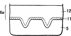
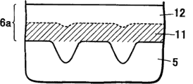
Fig. 6 is the sectional view of structure of the nitride semiconductor luminescent element of model utility ground expression embodiments of the invention 4 and 7.
Among the figure:
1, substrate
2, n type nitride semiconductor layer
3, active layer
4, p type nitride semiconductor layer
5, electroconductive oxide film
6, pad electrode (pad electrode)
6a, knitting layer
6b, pad layer
7, n pad electrode (pad electrode)
10, nitride semiconductor luminescent element
11, first metal film
12, current-diffusion layer
61, prolong conductive part
Embodiment
Below, by the description of drawings embodiments of the present invention.Just, execution mode shown below only is for specializing the example of the nitride semiconductor device that the technology of the present invention thought proposes, but does not represent that the present invention only limits to following execution mode.
Fig. 1 is the sectional view of the nitride semiconductor luminescent element 10 of expression embodiments of the present invention 1.As shown in Figure 1, constituting of the nitride semiconductor luminescent element of execution mode 1: on substrate 1 arbitrarily via one or more layers (not diagram) resilient coating etc., and press the sequential cascade of n type nitride semiconductor layer 2, active layer 3, p type nitride semiconductor layer 4, and in n type nitride semiconductor layer 2 and p type nitride semiconductor layer 4 connection electrode respectively.
In execution mode 1, be formed at the electrode on the p type nitride semiconductor layer 4, for example, constitute by the sequential cascade of electroconductive oxide film 5 that is electrically connected with nitride-based semiconductor and pad electrode (pad electrode) 6.And, pad electrode (pad electrode) the 6th is for being connected the electrode that forms with external circuit, facing up (when being key light picked-up face with the semiconductor layer side) when assembling, pad electrode (pad electrode) is connected with external circuit by lead-in wire bonding etc.And when flip-chip assemblies, that is, when with the substrate being key light picked-up face, pad electrode (padelectrode) is connected on the electrode of external circuit via eutectic layer [projection (bump): Ag, Au, Sn, In, Bi, Cu, Zn etc.].
In the nitride semiconductor luminescent element 10 of present embodiment 1, pad electrode (padelectrode) 6 has the knitting layer 6a that comprises first metal that whole of nitride semiconductor layer side is connected to electroconductive oxide film 5 mutually, has at the first included metal of described knitting layer 6a to be connected to first metal film electroconductive oxide film 5 and that formed by first metal mutually.
In present embodiment 1, make the value of its thickness when forming first metal film less than the average surface roughness Ra on electroconductive oxide film surface.Thus, not only can obtain can be to the whole face of the nitride semiconductor layer semiconductor element of input current equably, but also can obtain the semiconductor element that has good adaptation between electroconductive oxide film and the pad electrode (pad electrode).
And in present embodiment 1, the thickness of first metal film is formed on 5~
 Scope, and
 electroconductive oxide film 5 is formed by ITO.Thus, not only can obtain can be to the whole face of the nitride semiconductor layer semiconductor element of input current equably, but also can obtain the semiconductor element that has good adaptation between electroconductive oxide film and the pad electrode (pad electrode).And then, because the electroconductive oxide film is ITO, so can equably in the input current, efficiently switch on to the whole face of nitride semiconductor layer to semiconductor element.Particularly, further improve the light ingestion efficiency for nitride semiconductor luminescent element.
And, if first metal film forms as above-mentioned thickness, just further improve the adaptation between electroconductive oxide film and the pad electrode (pad electrode) on electroconductive oxide film 5, therefore even more ideal.
In the present embodiment, particularly the average surface roughness Ra on electroconductive oxide film surface is bigger than the thickness of first metal film, so can obtain good adaptation, is elaborated below by following research.First metal film is on the surface of electroconductive oxide film, and the average surface roughness Ra of electroconductive oxide film is bigger than the thickness of first metal film, become and have the concavo-convex of protuberance or recess etc. so have the surface of the electroconductive oxide film of average surface roughness Ra, and this concavo-convex surface has first metal film.And as shown in Figure 2, in the recess of electroconductive oxide film, oxidation film institute area surrounded can think that first metal is oxidized easily, and first a metal film part is oxidized.On the other hand, in the zones except that recess such as protuberance of electroconductive oxide film, can think and compare that first metal is difficult for oxidized with recess area, and as engaging of in the past metal level and electroconductive oxide film, electronics and cavity energy move expeditiously.Promptly be included in first metal in the knitting layer, in the oxidized zone of recess, combine with the oxygen of electroconductive oxide film and consolidate joint between electroconductive oxide film and the pad electrode (pad electrode), and, in the zone beyond the recess, move between pad electrode (padelectrode) and electroconductive oxide film expeditiously in electronics and hole, can think thus to access the semiconductor element with good adaptation and luminous efficiency.
For example, as shown in Figure 3, the film that constitutes by first metal, when its thickness is bigger than the average surface roughness Ra on electroconductive oxide film surface, though it is good in its adaptation of the part with oxide, but because the first not oxidized metal be integral body tabular to horizontal connection, so can think that first metal film 11 easily peels off.
But, as shown in Figure 2, first metal film 11, its thickness than the little situation of the average surface roughness Ra on the surface of electroconductive oxide film 5 under, the position of the upper surface of first metal film 11 on the recess of electroconductive oxide film 5 is lower than the surface of the protuberance of electroconductive oxide film.
If become this state, then not oxidized part just can tabularly not connect among first metal film 11, and becomes the state that zone oxidized and that adaptation is good disperses on first metal film 11.Thus, have, and the first not oxidized metal also is present in first metal film 11 in the adaptation that has improved first metal film, 11 integral body, thus can think can reduce and electroconductive oxide film 5 between contact resistance.
And, the average surface roughness Ra on electroconductive oxide film of the present invention surface, (SII company makes, and SPI3800N) measures can to pass through the scan detector microscope.
And, when the face of observing mensuration with the cross section (below, be called the mensuration face), can obtain based on the definition of the arithmetic average roughness Ra of JIS B0601.
According to JIS B0601, obtain average line (waviness curve) from the cross section curve of measuring face, and from cross section curve, deduct average line, that is,, average line obtains bold curve by being replaced as straight line.Then, according to the coordinate system of JIS B0601 definition, direction that will be consistent with the average line that is replaced as above-mentioned straight line is as X-axis, will be parallel to direction with the rectangular cross section of X-axis as the Z axle.
Only extract datum length l out from bold curve on X-direction, this extracts the average line of part out, can be represented by following formula (1).
Several 1
At this moment, average surface roughness Ra is Z (x) and Z
0The average absolute of difference, can obtain by following formula (2).
Several 2
Particularly, for example, use as microscope that TEM etc. can observe with high power, observation mensuration face in above-mentioned cross section, and obtain average line and bold curve from cross section curve.On X-axis, select the zone of 500nm arbitrarily, in the zone of selecting, get 100 X value (X with certain interval
1~X
100), and measure Z value [Z (x on each X value
1)~Z (x
100)].
From the Z value of having measured, Z
0Can obtain with formula (3).
Z
0=(1/100)×{Z(X
1)+Z(X
2)+Z(X
3)+…+Z(X
100)}(3)
The Z that utilization is obtained
0, average surface roughness Ra can obtain with formula (4).
Ra=(1/100)×{|Z(X
1)-Z
0|+|Z(X
2)-Z
0|+…+|Z(X
100)-Z
0|} (4)
In the present invention, this first metal preferably uses at least a metal of selecting from the cohort of being made up of titanium (Ti), zirconium (Zr), hafnium (Hf).If first metal is these metals, then in p pad electrode (pad electrode), can obtain and the electroconductive oxide film between good adaptation, and can reduce contact resistance.And, in n pad electrode (pad electrode), can obtain and nitride semiconductor layer between good adaptation, and can reduce contact resistance.Especially it is good using Ti.
And, in pad electrode (pad electrode) 6, the layer 6b above the knitting layer 6a (below, be called pad layer 6b), be the layer that comprises second metal different, and compare with knitting layer 6a with first metal, can also can not comprise first metal to comprise first metal than small scale.
And knitting layer 6a is different from first metal film 11, between first metal film 11 and pad layer 6b, for example, can comprise current-diffusion layer 12.This current-diffusion layer 12, it can be layer with first metal film 11 and the different compositions of pad layer 6b, perhaps shown in the embodiment 1 as described later, can make its via intermediate layer (not diagram) form with pad layer 6b difference, with the layer of pad layer 6b same composition, but this current-diffusion layer preferably is made of the material that is difficult to oxidation than first metal.Concrete material is select from W, Mo, Cd, Ni, Cu, Ag, Rh, Au, Pt, Pd at least a.Thus, owing in current-diffusion layer, be difficult for forming oxide, so can dissufion current in knitting layer.
As mentioned above, between knitting layer 6a and pad layer 6b, can have the intermediate layer that constitutes by the 3rd metal different with first metal and second metal.Form the 3rd metal in intermediate layer, for example, can select, that is: improve adaptation between knitting layer 6a and the pad layer 6b, prevent the diffusion etc. of the metal material of knitting layer 6a and/or pad layer 6b in conjunction with following purpose.
In the nitride semiconductor luminescent element 10 of present embodiment 1, can on this pad layer 6b, directly connect conductivity electric wire, eutectic layer, and on pad layer 6b, can also be provided with the layers such as Au that are used to connect conductivity electric wire, eutectic layer.Au is set if so, then owing to guaranteeing and the conductivity electric wire that for example is main component, good being connected of eutectic layer, so ideal with Au.
And, preferably, constitute pad layer or the second included metal of pad layer, on dominant wavelength from the light of nitride semiconductor luminescent element, its luminance factor first metal height.Thus, owing to can reflect the light that enters in the pad electrode (pad electrode), so can improve the light ingestion efficiency with this.
When pad layer 6b has multiple metal, be preferably in knitting layer 6a side and have the high metal of reflectivity.Thus, can more effectively reflect the light that enters in the pad electrode (pad electrode).
And, when second metal is the high metal of light reflectivity, be preferably knitting layer and pad layer joins.Thus, can more effectively reflect the light that enters in the pad electrode (pad electrode).
Second metal preferably uses select at least a from the cohort of being made of the high rhodium of light reflectivity (Rh), aluminium (Al), silver (Ag), platinum (Pt).If second metal is these metals, just can prevents the light absorption in pad electrode (pad electrode), thereby can absorb light expeditiously.If the item of particularly considering to prevent to move etc. is then preferably used Rh.And above-mentioned current-diffusion layer can comprise second metal.Thus, can absorb light more expeditiously.
The thickness of pad layer 6b as mentioned above, when directly connecting conductivity electric wire, eutectic layer on pad layer 6b, needs
 Above thickness.And, also be provided with on the
 pad layer 6b under the situation of layer that Au etc. is used to connect conductivity electric wire, eutectic layer, when pad layer 6b is made of the high metal of aforesaid reflectivity, if thickness is
 More than, just give full play to as the function that is used for catoptrical layer.
As the method for the pad electrode (pad electrode) that forms the present embodiment 1 that constitutes as described above, can enumerate as sputtering method etc.In present embodiment 1, can enumerate following method: for example by sputtering method film forming knitting layer 6a the time, use first metal, and form pad layer by halfway target (target) being replaced by second metal as target (target).
Be formed at the pad electrode (pad electrode) 6 on the electroconductive oxide film 5, can form and almost cover the whole of electroconductive oxide film 5, but preferably be configured to expose the part on electroconductive oxide film 5 surfaces.The shape of pad electrode (pad electrode) 6 is not particularly limited, and for example, can be polygonal various shapes such as circle, triangle, quadrangle.The size of pad electrode (padelectrode) 6 also is not particularly limited, so long as can to conductivity oxidation film 5, p type nitride semiconductor layer effectively the size of supplying electric current just can.
And for example, when constituting pad layer 6b by easy light absorbing material, preferably the absorption of the light that will send from active layer is limited to Min., and is set at the size that can absorb light expeditiously.
And, in nitride semiconductor luminescent element, usually, in a part of zone of nitride semiconductor luminescent element, remove the part of the depth direction arbitrarily of p type nitride semiconductor layer and active layer, n type nitride semiconductor layer, and the surface of exposing n type nitride semiconductor layer.Then, form n pad electrode (padelectrode) [that is, p pad electrode (pad electrode) and n pad electrode (pad electrode) are positioned at the one side side] on the surface of this n type nitride semiconductor layer that has exposed.
But in the present invention, n pad electrode (pad electrode) can be formed on n type nitride semiconductor layer and the face face opposition side that has formed electroconductive oxide film 5.When particularly being formed on the conductive boards such as nitride-based semiconductor at nitride semiconductor luminescent element, usually, because conductive board and n type nitride semiconductor layer are electrically connected, so n pad electrode (padelectrode) is electrically connected with n type nitride semiconductor layer via conductive board etc.
And, constitute the material of n pad electrode (pad electrode), preferably identical with the material that constitutes above-mentioned p pad electrode (pad electrode) 6 [below, the pad electrode on the above-mentioned conductivity oxide-film (pad electrode) is called p pad electrode (pad electrode)].Because first metal of above-mentioned listed p pad electrode (pad electrode) 6 is good with the adaptation of n type nitride semiconductor layer, the material that contact resistance is low, so, at the material that constitutes n pad electrode (pad electrode) is identical with p pad electrode (pad electrode) kind, when thickness is identical, can improve the adaptation between n pad electrode (pad electrode) and the n type nitride semiconductor layer, also can reduce simultaneously the contact resistance between n pad electrode (pad electrode) and the n type nitride semiconductor layer, therefore, can reduce contact resistance between n pad electrode (padelectrode) and the n type nitride semiconductor layer.
When forming p pad electrode (pad electrode) 6 and n pad electrode (padelectrode) with same material, the thickness of p pad electrode (pad electrode) 6 is preferably and forms thicklyer than the thickness of n pad electrode (pad electrode).About the knitting layer 6a of p pad electrode (pad electrode), thereby can think that a part by first metal absorbs the oxygen of electroconductive oxide film and the oxidized volume that causes increases.Thus, in p type pad electrode (pad electrode), because it has a lot of first metal oxides, therefore can improve adaptation with the electroconductive oxide film, when p pad electrode (pad electrode) 6 has catoptrical pad layer 6b, can improve the light ingestion efficiency in n pad electrode (pad electrode).
And then, p pad electrode (pad electrode) and n pad electrode (pad electrode) are in the structure with the one side side, if p pad electrode (pad electrode) 6 and n pad electrode (pad electrode) are same materials, just can form p pad electrode (pad electrode) and n pad electrode (pad electrode) with identical manufacturing process.If can be like this form p pad electrode (pad electrode) and n pad electrode (pad electrode) with identical manufacturing process, energy simplified manufacturing technique just, and obtain the nitride semiconductor luminescent element of cheapness, high reliability.
As the method that forms p pad electrode (pad electrode) and n pad electrode (pad electrode) with same material, identical manufacturing process, for example, have on electroconductive oxide film and n type nitride semiconductor layer, utilize resist (Resist) and form and to have after the mask of predetermined pattern (pattern), for example stack gradually knitting layer 6a and pad layer 6b by sputtering unit.
And, electroconductive oxide film 5, preferably include from by zinc (Zn), indium (In), tin (Sn), and the cohort formed of magnesium (Mg) the film of at least a element selected.More particularly, can list ZnO, In
2O
3, SnO
2, ITO (composite oxides of In and Sn).Wherein, ITO has high photopermeability in visible light (visibility region), and owing to be the high material of conductance, so can preferably use.
The upper surface side that is preferably at the electroconductive oxide film forms the good and transparent film of crystallinity.And in the low-density zone of the semiconductor side of electroconductive oxide film 5, a part can be noncrystalline (amorphous) film, is formed with transparent film or slightly sub-translucent film but be preferably.
This density regions preferably is suppressed in: from the border of p type nitride semiconductor layer, 10~50% scope of the full thickness of electroconductive oxide film.Like this by the density step-down of p type nitride semiconductor layer side just, can reduce the contact resistance with p type nitride semiconductor layer, and can obtain good light transmittance.And the density height of the face side of electroconductive oxide film thus, obtains the good adaptation between the knitting layer of electroconductive oxide film and pad electrode (pad electrode).
And the full thickness of electroconductive oxide film 5 is not particularly limited, and for example, can be set at 100~1000nm.And density regions can be set at 10~500nm.
And preferably, electroconductive oxide film 5 does not only absorb visible light, nor absorb the light that for example produces from the active layer that forms by above-mentioned gallium nitride compound semiconductor, promptly, wavelength is contiguous at 360nm~650nm, the light of the wavelength of 380nm~560nm, 400nm~600nm preferably, thus with light transmittance for example more than 90% or more than 85%, 80% with the printing opacity expeditiously that comes up.Thus, the electrode that can be used as the nitride semiconductor luminescent element of desired wavelength is used.
Particularly, for example when film forming ITO film, can enumerate target (target) that the ITO film forming uses and the method for coming film forming electroconductive oxide film by sputtering unit etc. used.And, can also enumerate by vacuum evaporation method of film forming etc. in room temperature or high temperature.
In addition, for example also can after having formed the ITO film, the electroconductive oxide film be heat-treated.As heat treatment method, annealing in process that annealing laser handles, carries out with heating furnace etc. is for example arranged.And the processing as after the ITO film film forming also can utilize the laser ablation method.And, also can these methods of combination in any.
And, can list following method as the method that on film thickness direction, forms the electroconductive oxide film of different densities: for example, when coming film forming electroconductive oxide film, for example ITO film by sputtering method, gas as sputter gas that oxygen partial pressure is little or zero is replaced by the big gas of dividing potential drop or is increased the method that oxygen partial pressure utilizes gradually; Except the target (target) that the ITO film forming is used, use many target (target) or the few targets (target) of amount of oxygen of In amount, be replaced by the method for the few target (target) of many targets (target) of In amount or amount of oxygen halfway; The input power that increases sputtering unit gradually or is sharply come method of film forming etc.Can also list in addition: when coming film forming electroconductive oxide film, for example ITO film by vacuum evaporation, sharply or gradually make the temperature rising of semiconductor layer or the method that descends; The method that rate of film build is descended; The use ion gun shines the method for oxonium ion etc. in film forming procedure.
Can list in addition, after forming electroconductive oxide film, for example ITO film, for example (particularly at reducibility gas, carbon monoxide, hydrogen, argon gas etc., perhaps these two or more mists) under the condition, under 200~650 ℃ temperature, carry out the method etc. of the annealing in process of stipulated time corresponding to the thickness of electroconductive oxide film.And also can form after the electroconductive oxide film for example heat-treats in the process of ITO film the rapid heat treatment of multistep such as continue film forming and heat-treat.And, as heat-treating methods, annealing in process that radium-shine annealing (Lamp Anneal) handles, carries out with heating furnace etc. is for example arranged.As the processing after the ITO film film forming, can utilize electron beam irradiation, laser ablation method etc.And, can these methods of combination in any.
As the substrate that forms nitride semiconductor luminescent element of the present invention, for example, can adopt known insulating properties substrate or conductive boards such as sapphire, spinelle, SiC, nitride-based semiconductor (as GaN etc.), GaAs.The insulating properties substrate finally also can be removed, and also can not remove.When finally not removing the insulating properties substrate, usually, p electrode and n electrode all are formed on the same one side side on the semiconductor layer.And when finally removing the insulating properties substrate or use conductive board, as mentioned above, p electrode and n electrode all can be formed on the same one side side on the nitride semiconductor layer, also can be respectively formed at not on the coplanar.
As n type and p type nitride semiconductor layer and active layer, be not particularly limited, for example, can suitably use In
xAl
YGa
1-x-YThe gallium nitride compound semiconductor of N (0≤X, 0≤Y, X+Y≤1) etc.These nitride semiconductor layers can be respectively single layer structures, also can be different the compositions and the stepped construction of thickness etc., superlattice structure etc.Active layer is preferably especially, with the single quantum well of the stacked film that produces quantum effect or the structure of multiple quantum well.And, can omit active layer.
And usually, this nitride semiconductor layer can be used as and has MIS engages, PIN engages or PN engages homostyructure, heterostructure or double-heterostructure and wait and constitute.Nitride semiconductor layer for example can form by MOVPE, organic metal vapor growth method (MOCVD), hydride gas phase epitaxial growth method (HVPE), molecular beam epitaxial growth method technique known such as (MBE).And the thickness of nitride semiconductor layer does not have qualification especially, can be suitable for various thickness.
And, stepped construction as nitride semiconductor layer, for example, can list: the active layer of the multiple quantum well structure of the superlattice layer of the resilient coating that constitutes by AlGaN, the GaN layer that undopes, the n side contact layer that constitutes by the n type GaN that mixes Si, stacked mutually GaN layer and InGaN layer, stacked mutually GaN layer and InGaN layer, the stacked mutually superlattice layer of mixing the AlGaN layer of Mg and mixing the InGaN layer of Mg, the p side contact layer that constitutes by the GaN that mixes Mg etc.
Fig. 4 is the fragmentary cross-sectional view of the nitride semiconductor luminescent element of expression embodiments of the present invention 2.Except the item that the following describes, other identical with execution mode 1.
In present embodiment 2, on the knitting layer 6a of pad electrode (pad electrode) 6, comprise as the alloy film layer that is connected to the electroconductive oxide film mutually, that constitute by the alloy of first metal and second metal.Thus, can improve adaptation between pad electrode (pad electrode) 6 and the electroconductive oxide film 5.And, when knitting layer is made of the alloy of first metal and second metal, can improve adaptation, and then when second metal is the high material of reflectivity, can improve the light ingestion efficiency of pad electrode (pad electrode) with minimal material.
And second metal when high, if strengthen the ratio of second metal of above-mentioned alloy, just can improve the reflection of light rate than the first metallic reflection rate in the dominant wavelength of nitride semiconductor luminescent element, and raising light ingestion efficiency.
As implement as described in the mode 2, when the alloy by first metal and second metal forms knitting layer, the thickness of knitting layer, for example can be set at 50~
 If the thickness of this scope just improves adaptation effectively.Therefore, in the structure of
 present embodiment 2, need not must be thinner as the film that constitutes by first metal in the enforcement mode 1 with film thickness monitoring, thus improve rate of finished products.
In the pad electrode (pad electrode) 6 of execution mode 2, on knitting layer 6a, during pad layer that second metal that luminance factor first metal is high in being provided with by the dominant wavelength at nitride semiconductor luminescent element constitutes, if for example the thickness of knitting layer 6a is made as 50~
The adaptation of then above-mentioned pad electrode (pad electrode) is good, and can improve the light ingestion efficiency, so be more preferably.
First metal in the knitting layer 6a of execution mode 2 and the alloy ratio of second metal are preferably first tenor at 10~40wt%.If first tenor below 10wt%, then and the contact resistance between the nitride-based semiconductor uprise, if first tenor more than 40wt%, then the reflection of light rate descends.If first tenor is at 10~40wt%, then in p pad electrode (pad electrode), just have and the electroconductive oxide film between good adaptation, can reduce contact resistance simultaneously.And, in n pad electrode (pad electrode), have and nitride semiconductor layer between good adaptation, simultaneously can reduce contact resistance.And then first tenor is set in 15~30wt% and then is more preferably.
In present embodiment 2, electroconductive oxide film 5 also is preferably has concavo-convex surface.If this concavo-convex surface is arranged,,, can further improve adaptation at the just easy oxide that forms first metal of the boundary vicinity of knitting layer 6a and electroconductive oxide film particularly at recess.
As the method that forms the knitting layer 6a that forms by this alloy, can enumerate: for example, with the alloy of first metal and second metal the method for utilizing the sputtering method film forming as target (target) use.As first metal of target (target) use and the alloy of second metal, can enumerate: for example, the sintered body of first metal and second metal etc.
In present embodiment 2, when using same material to form p pad electrode (pad electrode) 6 and n pad electrode (pad electrode), the thickness of Film Thickness Ratio n pad electrode (pad electrode) that is preferably p pad electrode (pad electrode) is thick.Thus, the adaptation between p pad electrode (pad electrode) and the electroconductive oxide film can be improved, and the light ingestion efficiency of n pad electrode (pad electrode) can be improved.
And in the nitride semiconductor luminescent element of the embodiments of the present invention 1 of above explanation and 2, p pad electrode (pad electrode) 6 for example as shown in Figure 5, is preferably and has the shape that prolongs conductive part 61.If pad electrode (pad electrode) 6 has this prolongation conductive part 61, just can make active layer integral body luminous expeditiously, nitride semiconductor luminescent element particularly of the present invention, effect was better when p pad electrode (pad electrode) formation face was key light picked-up face.And, have above-mentioned knitting layer and pad layer owing to prolong conductive part, therefore have and the electroconductive oxide film between good adaptation, and can reduce contact resistance.And then, when second metal is the high material of reflectivity, improve the light ingestion efficiency.
And, in Fig. 5, the 2nd, n type nitride semiconductor layer, the 4th, p type nitride semiconductor layer, the 7th, n pad electrode (pad electrode).
Particularly as shown in Figure 5, when p side and n pad electrode (pad electrode) are formed on same one side side on the nitride semiconductor layer, usually, n pad electrode (pad electrode) 7 is formed at least one limit of approaching nitride semiconductor luminescent element.For example, as shown in Figure 5, n pad electrode (pad electrode) 7 is set at two limits in a bight of approaching nitride semiconductor luminescent element, and p pad electrode (pad electrode) 6 is preferably and is set at other bights that become the diagonal angle with the approaching bight of n pad electrode (pad electrode) 7.
And the prolongation conductive part 61 of p pad electrode (pad electrode) 6 extends across the bight at welding disk place and along the limit of adjacency.Thus, can make the active layer that is positioned between p pad electrode (pad electrode) 6 and the n pad electrode (pad electrode) 7 luminous expeditiously, and then, be connected in the prolongation conductive part 61 of p pad electrode (pad electrode) 6 and make it to conduct by formation on electroconductive oxide film 5, thus can be more effectively to the whole dissufion current of p type nitride semiconductor layer, and can make active layer integral body luminous expeditiously.And then, obtain the light of high brightness at p pad electrode (pad electrode) 6 and the periphery that prolongs conductive part 61.
In above execution mode 1 and 2, the example that has formed electroconductive oxide film and p pad electrode (pad electrode) on p type nitride semiconductor layer has been described, but the present invention is not limited only to this, even on n type nitride semiconductor layer, formed the nitride semiconductor luminescent element of electroconductive oxide film and n pad electrode (pad electrode), also can access same functional effect.
Embodiment
The nitride semiconductor luminescent element of present embodiment is described based on Fig. 1.This nitride semiconductor luminescent element 10, be the stacked resilient coating that constitutes by AlGaN on sapphire substrate 1 (not diagram), non-impurity-doped GaN layer (not diagram), and thereon, stack gradually n type nitride semiconductor layer 2, active layer 3, p type nitride semiconductor layer 4 and constitute.Wherein, the n type contact layer that n type nitride semiconductor layer 2 is stacked is made of the GaN that mixes Si, and superlattice n type metal bag (clad) layer of stacked mutually GaN layer and InGaN layer; The formed multiple quantum well structure in second barrier layer that active layer 3 is repeatedly mutually stacked first barrier layers that are initially the barrier layer that is made of the GaN that undopes and the well layer that is made of InGaN then, are made of InGaN, be made of the GaN that undopes; P type nitride semiconductor layer 4 is the AlGaN layer of the stacked Mg of mixing mutually and the superlattice p type clad of mixing the InGaN layer of Mg, reaches the p type contact layer that is made of the GaN that mixes Mg.
In a part of zone of n type nitride semiconductor layer 2, remove stacked active layer 3 and p type nitride semiconductor layer 4 thereon, and remove 2 of n type nitride semiconductor layers and expose in the part of thickness direction, on its exposed n type nitride semiconductor layer 2, form n pad electrode (pad electrode) 7.
On p type nitride semiconductor layer 4, almost on whole, be formed with the electroconductive oxide film 5 that constitutes by ITO, and, on the part of this electroconductive oxide film 5, be formed with pad electrode (pad electrode) 6.
The nitride semiconductor luminescent element of present embodiment 1 is to be made by following manufacture method.
The formation of semiconductor layer
Be on 2 inches the sapphire substrate, to use the MOVPE reaction unit at diameter, generate successively: by Al
0.1Ga
0.9The resilient coating that N constitutes
 Non-impurity-doped GaN layer 1.5 μ m; N type
 nitride semiconductor layer 2, the n type contact layer 2.165 μ m that its GaN of mixing Si of serving as reasons constitutes, stacked ten GaN layers mutually
 With the InGaN layer
Superlattice n type clad
With the InGaN layer
Superlattice n type clad
Active layer 3, its structure for each mutual repeatedly stacked six layers of initial thickness is
 The barrier layer that constitutes by the GaN that undopes, thickness is then
 By In
0.3Ga
0.7Well layer, thickness that N constitutes are
By In
0.3Ga
0.7Well layer, thickness that N constitutes are

 By In
0.02Ga
0.98First barrier layer, thickness that N constitutes are
By In
0.02Ga
0.98First barrier layer, thickness that N constitutes are
 The formed multiple quantum well structure in second barrier layer that constitutes by the GaN that undopes (total film thickness is
 ); P type
 nitride semiconductor layer 4, it is for mixing the Al of Mg mutually for stacked ten times
0.1Ga
0.9The N layer
 With the InGaN layer of mixing Mg
 Superlattice p type clad 0.2 μ m, the thickness of the p type contact layer 0.5 μ m that constitutes by the GaN that mixes Mg, make wafer thus.
Etching
Resulting wafer in reaction vessel, is annealed with 600 ℃ of temperature in nitrogen, and further reduce the resistance of p type clad and p type contact layer.
After the annealing, from reaction vessel, take out wafer, form the mask of regulation shape on the surface of the p of the superiors type contact layer, use Etaching device, above mask, begin to carry out etching, and expose the part of n type contact layer.
The formation of ITO film
After removing mask, wafer is set in sputtering unit, and in sputtering unit, is provided with by In
2O
3And SnO
2The oxide target (target) that constitutes of sintered body.Utilize sputtering unit on almost whole of the p of wafer type contact layer 8, to form thickness to be
 And be as the average surface roughness Ra on the surface of
 electroconductive oxide film 5
 The ITO film.
The formation of pad electrode (pad electrode) 6
On electroconductive oxide film 5, utilize resist (Resist) to form and have the mask of predetermined pattern, and in the above, stack gradually
 And, form pad electrode (pad electrode) 6 by method of stripping.Thereafter, on n type contact layer, with
 Thickness form the n pad electrode (padelectrode) 7 that constitutes by W/Pt/Au.
Then, in annealing device, heat-treat with the temperature more than 300 ℃.
Resulting wafer in the cutting of regulation place, thus, is obtained nitride semiconductor luminescent element 10.That is, in the nitride semiconductor luminescent element of embodiment 1, knitting layer 6a by by
First metal film 11 that constitutes of Ti film and by
The current-diffusion layer 12 that constitutes of Rh layer form, and via with
 The intermediate layer that constitutes of Au layer, form as
 pad layer 6b's

 The Rh layer.
The nitride semiconductor luminescent element of the embodiment 1 of Xing Chenging has good adaptation between its electroconductive oxide film and the pad electrode (pad electrode), and can reduce contact resistance thus.And, improve the light ingestion efficiency.
The nitride semiconductor luminescent element of embodiment 2, in the nitride semiconductor luminescent element of embodiment 1, except form pad electrode (pad electrode) 6 with following method, other structures are identical.
The formation of pad electrode (pad electrode) 6
On conductivity oxide-film 5, utilize resist (Resist) to form mask with predetermined pattern, in the above, as knitting layer 6a formation thickness be
 Ti, and above it, form thickness as
 pad layer 6b and be
 Rh.Form this Rh and cover whole of Ti, also play a role thus as current-diffusion layer.And, by forming thickness in the above be
 Au, and by method of stripping, form pad electrode (pad electrode) 6.After this, on n type contact layer with
 Thickness form the n pad electrode (pad electrode) 7 that constitutes by W/Pt/Au.
Secondly, in annealing device, heat-treat with the temperature more than 300 ℃.
Cut at the regulation place by the wafer that will obtain, obtain nitride semiconductor luminescent element 10 thus.
The nitride semiconductor luminescent element of this embodiment 2 more can improve reflection of light rate at p pad electrode (pad electrode) than the nitride semiconductor luminescent element of embodiment 1, and further improve the light ingestion efficiency.
As a comparative example 1, except with Rh/Pt/Au as p pad electrode (pad electrode), with W/Pt/Au as the n pad electrode (pad electrode), make nitride semiconductor luminescent element by the method identical with embodiment 2, and compare with the nitride semiconductor luminescent element of embodiment 2, just confirm the still nitride semiconductor luminescent element of embodiment 2, the closing force between its electroconductive oxide film and the p pad electrode (pad electrode) is high 1.4 times than comparative example 1.
And then, as a comparative example 2, except the thickness of the Ti that makes pad electrode (pad electrode) 6 is
In addition, make nitride semiconductor luminescent element by the method identical with embodiment 2, and with the p pad electrode (pad electrode) of above-mentioned comparative example 1 be that Rh/Pt/Au, n pad electrode (pad electrode) are the comparison of W/Pt/Au, the closing force of electroconductive oxide film and p pad electrode (pad electrode) is roughly the same.
Further, as a comparative example 3, except the Ti thickness that makes p pad electrode (pad electrode) 6 is
 In addition, make by the method identical with
 embodiment 2, p pad electrode (padelectrode) is just peeled off from the electroconductive oxide film, and can not obtain nitride semiconductor luminescent element.
The nitride semiconductor luminescent element of this embodiment 3, as shown in Figure 6, in the manufacturing process of embodiment 2, forming n pad electrode (pad electrode) 7 o'clock, by forming n pad electrode (pad electrode) 7, and make the thick nitride semiconductor luminescent element of thickness of knitting layer of Film Thickness Ratio n pad electrode (pad electrode) 7 of the knitting layer 6a of p pad electrode (pad electrode) 6 with p pad electrode (pad electrode) 6 identical materials.
The nitride semiconductor luminescent element of this embodiment 3 except the effect of embodiment 2, can also improve the reflection of light rate at n pad electrode (pad electrode), and further improve the light ingestion efficiency.And, even compare with the situation of the knitting layer of n pad electrode (pad electrode) with the knitting layer that forms p pad electrode (pad electrode) with identical thickness, also still with the state of good adaptation, raising is in the reflection of light rate of n pad electrode (pad electrode), and further improves the light ingestion efficiency of nitride semiconductor luminescent element.
The nitride semiconductor luminescent element of this embodiment 4, as shown in Figure 6, in the manufacturing process of embodiment 2, forming pad electrode (pad electrode) 6 o'clock, except utilization forms n pad electrode (padelectrode) 7 with p pad electrode (pad electrode) 6 identical materials, in same operation, other identical with embodiment 2 made nitride semiconductor luminescent element.
And in present embodiment 4, the pad electrode of p side and n side (pad electrode) can form by the following method.
On electroconductive oxide film 5 that constitutes by ITO and the n type contact layer that exposes, utilize resist (Resist) to form mask with predetermined pattern, in the above, form thickness as knitting layer 6a and be
 Ti, in the above, form thickness as
 pad layer 6b and be
Rh, form thickness again and be
 Au, and form p pad electrode (pad electrode) 6 and n pad electrode (pad electrode) 7 by method of stripping.
Afterwards, in annealing device, heat-treat with the temperature more than 300 °.
Resulting wafer is cut at the regulation place, obtain the nitride semiconductor luminescent element 10 of embodiment 4 thus.
The nitride semiconductor luminescent element of Xing Chenging thus, more can improve reflection of light rate than embodiment 2 at n pad electrode (pad electrode), and, when further improving the light ingestion efficiency of nitride semiconductor luminescent element, can simplify manufacturing process.
The nitride semiconductor luminescent element of present embodiment 5 is embodiment that embodiments of the present invention 2 as shown in Figure 4 are correlated with.That is, the nitride semiconductor luminescent element of present embodiment 5 is that other the nitride semiconductor luminescent element with embodiment 2 is identical formation except the metal material difference of the knitting layer in p pad electrode (pad electrode) 6.
Particularly, in the nitride semiconductor luminescent element of present embodiment 5, the knitting layer of p pad electrode (pad electrode) 6 is formed by the alloy of Ti and Rh.
P pad electrode (padelectrode) 6 in the nitride semiconductor luminescent element of present embodiment 5 is made according to the following steps.
At first, after having formed the electroconductive oxide film 5 that constitutes by ITO, on electroconductive oxide film 5, utilize resist (Resist) to form the mask of predetermined pattern.Then, the target (target) that the alloy by Ti and Rh constitutes is set in sputtering unit, and utilizes sputtering unit, with
 The stacked Ti of thickness and the alloy of Rh.Then, respectively with Rh, Au as target (target), and by sputter successively respectively with
Thickness stacked.Afterwards, form p pad electrode (pad electrode) 6 by method of stripping.
The stacked Ti of thickness and the alloy of Rh.Then, respectively with Rh, Au as target (target), and by sputter successively respectively with
Thickness stacked.Afterwards, form p pad electrode (pad electrode) 6 by method of stripping.
And in the present embodiment, the ratio of the Ti in the alloy of Ti and Rh is 25wt%.
The nitride semiconductor luminescent element of present embodiment 5 than the nitride semiconductor luminescent element of embodiment 1, more can improve the reflection of light rate at p pad electrode (pad electrode), and further improve the light ingestion efficiency.
As a comparative example, gone out with Rh/Pt/Au as p pad electrode (pad electrode), with W/Pt/Au in addition as n pad electrode (pad electrode), make nitride semiconductor luminescent element by the method identical with embodiment 5, compare with the nitride semiconductor luminescent element of embodiment 5, just confirm the still nitride semiconductor luminescent element of embodiment 5, the closing force between its electroconductive oxide film and the p pad electrode (pad electrode) is high 1.4 times than the nitride semiconductor luminescent element of comparative example.
And in the nitride semiconductor luminescent element of present embodiment 5, the light ingestion efficiency of pad electrode (padelectrode) is also very remarkable.
The nitride semiconductor luminescent element of present embodiment 6, in the manufacturing process of embodiment 5, forming n pad electrode (pad electrode) 7 o'clock, use with p pad electrode (pad electrode) identical materials and form n pad electrode (pad electrode) 7, and the thick nitride semiconductor luminescent element of thickness of the knitting layer of the Film Thickness Ratio n pad electrode (pad electrode) of the knitting layer 6a of making p pad electrode (pad electrode) 6.
The nitride semiconductor luminescent element of present embodiment 6 except the effect that can obtain embodiment 5, can also improve the reflection of light rate at n pad electrode (pad electrode), and further improve the light ingestion efficiency.And, even compare with the situation of the knitting layer of n pad electrode (pad electrode) with the knitting layer that forms p pad electrode (padelectrode) with identical thickness, also still with the state of good adaptation, can improve reflection of light rate, and further improve the light ingestion efficiency of nitride semiconductor luminescent element at n pad electrode (pad electrode).
The nitride semiconductor luminescent element of present embodiment 7, in the manufacturing process of embodiment 5, when forming pad electrode (pad electrode), form simultaneously the n pad electrode (pad electrode) except using, make by the method identical with embodiment 5 with p pad electrode (pad electrode) identical materials.
That is, this nitride semiconductor luminescent element, the knitting layer 6a of p pad electrode (pad electrode) 6 are that alloy by Ti and Rh forms.And with the join part of side of this n pad electrode (padelectrode) 7 and n type nitride semiconductor layer, also the alloy by Ti and Rh forms.
The pad electrode (padelectrode) of the p side of the nitride semiconductor luminescent element of present embodiment 7 and n side forms by the following method.
At first, after forming the electroconductive oxide film that constitutes by ITO, expose at the electroconductive oxide film and by etching on the n type nitride semiconductor layer, utilize resist (Resist) to form mask with predetermined pattern.Secondly, the target (target) that the alloy by Ti and Rh constitutes is set in sputtering unit, and by sputtering unit, the alloy of stacked Ti and Rh.Then, respectively with Rh, Au as target (target), and stack gradually by sputter.Afterwards, form p pad electrode (pad electrode) 6 and n pad electrode (pad electrode) 7 by method of stripping.
In the nitride semiconductor luminescent element of present embodiment 7, more can improve reflection of light rate than embodiment 5 at n pad electrode (pad electrode), and further improve the light ingestion efficiency of nitride semiconductor luminescent element, and can simplify production process.
Industrial applicibility
Nitride semiconductor device of the present invention is fit to be used in formation background light source, display, photograph On the semiconductor light-emitting elements of the various light sources such as bright, vehicle lamp and optical semiconductor sensing device etc. other On the semiconductor devices.
Claims (20)
1. nitride semiconductor device, it has nitride semiconductor layer, it is characterized in that:
On above-mentioned nitride semiconductor layer, have electroconductive oxide film, pad electrode successively;
Above-mentioned pad electrode, whole knitting layer that comprises first metal and the pad layer that comprises second metal different that is connected to above-mentioned electroconductive oxide film mutually with above-mentioned nitride-based semiconductor side with above-mentioned first metal;
Above-mentioned knitting layer has first metal film that is connected to above-mentioned electroconductive oxide film mutually and is made of first metal;
The thickness of above-mentioned first metal film is less than the value of above-mentioned electroconductive oxide film surface average roughness Ra.
2. nitride semiconductor device according to claim 1 is characterized in that:
Above-mentioned knitting layer comprises current-diffusion layer on above-mentioned first metal film.
3. nitride semiconductor device according to claim 2 is characterized in that:
Between above-mentioned knitting layer and above-mentioned pad layer, has the intermediate layer that constitutes by the 3rd metal different with above-mentioned first metal and above-mentioned second metal.
4. nitride semiconductor device according to claim 2 is characterized in that:
Above-mentioned current-diffusion layer comprises above-mentioned second metal.
5. nitride semiconductor device according to claim 1 is characterized in that:
Above-mentioned electroconductive oxide film, comprise from by zinc, indium, tin, and the group that forms of magnesium at least a element selected.
6. nitride semiconductor device according to claim 1 is characterized in that:
Above-mentioned electroconductive oxide film is ITO.
7. nitride semiconductor device, it has nitride semiconductor layer, it is characterized in that:
On above-mentioned nitride semiconductor layer, have electroconductive oxide film, pad electrode successively;
Above-mentioned pad electrode has knitting layer that comprises first metal that is connected to above-mentioned electroconductive oxide film mutually and the pad layer that comprises second metal different with above-mentioned first metal;
Above-mentioned knitting layer comprises the alloy film that is made of the alloy of above-mentioned first metal and above-mentioned second metal, and as the layer that is connected to above-mentioned electroconductive oxide film mutually.
8. nitride semiconductor device according to claim 7 is characterized in that:
Above-mentioned knitting layer is to be made of above-mentioned alloy film.
9. nitride semiconductor device according to claim 7 is characterized in that:
Above-mentioned electroconductive oxide film, comprise from by zinc, indium, tin, and the group that forms of magnesium at least a element selected.
10. nitride semiconductor device according to claim 7 is characterized in that:
Above-mentioned electroconductive oxide film is ITO.
11. a nitride semiconductor device, it has nitride semiconductor layer, it is characterized in that:
On above-mentioned nitride semiconductor layer, have the electroconductive oxide film, the pad electrode that constitute by ITO successively;
Above-mentioned pad electrode, whole knitting layer that comprises first metal and the pad layer that comprises second metal different that is connected to above-mentioned electroconductive oxide film mutually with above-mentioned nitride-based semiconductor side with above-mentioned first metal;
Above-mentioned knitting layer has first metal film that is connected to above-mentioned electroconductive oxide film mutually and is made of first metal;
The thickness of above-mentioned first metal film exists
 Scope in.
12. nitride semiconductor device according to claim 11 is characterized in that:
The thickness of above-mentioned first metal film is less than the value of above-mentioned electroconductive oxide film surface average roughness Ra.
13. nitride semiconductor device according to claim 11 is characterized in that:
Above-mentioned knitting layer comprises current-diffusion layer on above-mentioned first metal film.
14. nitride semiconductor device according to claim 13 is characterized in that:
Between above-mentioned knitting layer and above-mentioned pad layer, has the intermediate layer that constitutes by the 3rd metal different with above-mentioned first metal and above-mentioned second metal.
15. nitride semiconductor device according to claim 13 is characterized in that:
Above-mentioned current-diffusion layer comprises above-mentioned second metal.
16., it is characterized in that according to any described nitride semiconductor device in the claim 1 to 15:
The part of included above-mentioned first metal is oxidized in the above-mentioned knitting layer.
17., it is characterized in that according to any described nitride semiconductor device in the claim 1 to 15:
Above-mentioned nitride semiconductor layer comprises the n type nitride semiconductor layer and the p type nitride semiconductor layer that are formed with the n pad electrode;
On above-mentioned p type nitride semiconductor layer, form above-mentioned electroconductive oxide film;
Above-mentioned pad electrode is formed in the p pad electrode on the above-mentioned conductivity oxide-film;
The said n pad electrode is identical with the formation of above-mentioned p pad electrode.
18., it is characterized in that according to any described nitride semiconductor device in the claim 1 to 15:
Above-mentioned first metal is the material of selecting from the group that is made up of Ti, Zr, Hf and constituting.
19., it is characterized in that according to any described nitride semiconductor device in the claim 1 to 15:
Above-mentioned nitride semiconductor device is a light-emitting component, and above-mentioned second metal is higher than above-mentioned first metal for its reflectivity of the light that sends.
20., it is characterized in that according to any described nitride semiconductor device in the claim 1 to 15:
Above-mentioned nitride semiconductor device is a light-emitting component, and second metal is the material of selecting from the group that is made up of Rh, Al, Ag, Pt and constituting.
Applications Claiming Priority (2)
| Application Number | Priority Date | Filing Date | Title |
|---|---|---|---|
| JP2005146952 | 2005-05-19 | ||
| JP2005146952A JP5138873B2 (en) | 2005-05-19 | 2005-05-19 | Nitride semiconductor device |
Publications (2)
| Publication Number | Publication Date |
|---|---|
| CN1866560A CN1866560A (en) | 2006-11-22 |
| CN100555683C true CN100555683C (en) | 2009-10-28 |
Family
ID=36791571
Family Applications (1)
| Application Number | Title | Priority Date | Filing Date |
|---|---|---|---|
| CNB2006100827147A Active CN100555683C (en) | 2005-05-19 | 2006-05-18 | Nitride semiconductor device |
Country Status (6)
| Country | Link |
|---|---|
| US (1) | US8981420B2 (en) |
| EP (1) | EP1724847B1 (en) |
| JP (1) | JP5138873B2 (en) |
| KR (1) | KR101161897B1 (en) |
| CN (1) | CN100555683C (en) |
| TW (1) | TWI382563B (en) |
Families Citing this family (21)
| Publication number | Priority date | Publication date | Assignee | Title |
|---|---|---|---|---|
| WO2008047923A1 (en) * | 2006-10-20 | 2008-04-24 | Mitsubishi Chemical Corporation | Nitride semiconductor light-emitting diode device |
| CN102779918B (en) | 2007-02-01 | 2015-09-02 | 日亚化学工业株式会社 | Semiconductor light-emitting elements |
| JP5040355B2 (en) * | 2007-02-24 | 2012-10-03 | 日亜化学工業株式会社 | Semiconductor light emitting device and light emitting device having the same |
| JP2008244161A (en) * | 2007-03-27 | 2008-10-09 | Toyoda Gosei Co Ltd | Method for forming electrode of group iii nitride-based compound semiconductor light-emitting element |
| TWI366291B (en) * | 2007-03-30 | 2012-06-11 | Epistar Corp | Semiconductor light-emitting device having stacked transparent electrodes |
| JP2008282979A (en) * | 2007-05-10 | 2008-11-20 | Sharp Corp | Semiconductor light-emitting element, and manufacturing method thereof |
| KR101457204B1 (en) * | 2008-02-01 | 2014-11-03 | 서울바이오시스 주식회사 | Light emitting device and method for manufacturing thereof |
| US20110018022A1 (en) * | 2008-03-13 | 2011-01-27 | Okabe Takehiko | Semiconductor light-emitting device and method for manufacturing the same |
| JP2010062425A (en) * | 2008-09-05 | 2010-03-18 | Showa Denko Kk | Semiconductor light emitting device and method of manufacturing the same, and lamp |
| CN102124574B (en) | 2008-06-16 | 2013-07-17 | 丰田合成株式会社 | Semiconductor light emitting element, electrode and manufacturing method for the element, and lamp |
| WO2011111642A1 (en) * | 2010-03-08 | 2011-09-15 | 日亜化学工業株式会社 | Semiconductor light-emitting element, and method for producing same |
| KR101158080B1 (en) | 2010-07-22 | 2012-06-22 | 서울옵토디바이스주식회사 | Light emitting diode |
| BR112013014356B1 (en) * | 2010-12-08 | 2021-01-12 | Nichia Corporation | semiconductor light emitting device of the nitride group |
| JP2012138465A (en) * | 2010-12-27 | 2012-07-19 | Showa Denko Kk | Group-iii nitride semiconductor light-emitting element manufacturing method, group-iii nitride semiconductor light-emitting element, lamp, electronic apparatus and machinery |
| JP4960511B1 (en) | 2011-01-26 | 2012-06-27 | 株式会社東芝 | Semiconductor light emitting device and manufacturing method thereof |
| JP6077201B2 (en) | 2011-08-11 | 2017-02-08 | 昭和電工株式会社 | Light emitting diode and manufacturing method thereof |
| JP2012191232A (en) * | 2012-06-05 | 2012-10-04 | Mitsubishi Chemicals Corp | GaN BASED LIGHT EMITTING DIODE ELEMENT |
| JP6023660B2 (en) * | 2013-05-30 | 2016-11-09 | スタンレー電気株式会社 | Semiconductor light emitting device and semiconductor light emitting device |
| JP5705950B2 (en) * | 2013-11-18 | 2015-04-22 | 株式会社東芝 | Semiconductor light emitting device |
| CN104109839A (en) * | 2014-07-04 | 2014-10-22 | 宜昌南玻显示器件有限公司 | ITO film and preparation method thereof |
| JP2018006535A (en) * | 2016-06-30 | 2018-01-11 | ウシオ電機株式会社 | Semiconductor light-emitting device |
Family Cites Families (50)
| Publication number | Priority date | Publication date | Assignee | Title |
|---|---|---|---|---|
| JPH08250540A (en) | 1995-03-13 | 1996-09-27 | Toyoda Gosei Co Ltd | Semiconductor device |
| JP3309756B2 (en) | 1997-02-14 | 2002-07-29 | 豊田合成株式会社 | Gallium nitride based compound semiconductor device |
| JPH10256602A (en) | 1997-03-12 | 1998-09-25 | Sharp Corp | Semiconductor light emitting device |
| JPH10308533A (en) | 1997-05-09 | 1998-11-17 | Toshiba Corp | Galium-nitride-based compound semiconductor light emitting element, its manufacture and light emitting element |
| JPH118410A (en) | 1997-06-18 | 1999-01-12 | Nichia Chem Ind Ltd | Electrode of n-type nitride semiconductor |
| JPH11220168A (en) * | 1998-02-02 | 1999-08-10 | Toyoda Gosei Co Ltd | Gallium nitride compound semiconductor device and manufacture thereof |
| JP4183299B2 (en) * | 1998-03-25 | 2008-11-19 | 株式会社東芝 | Gallium nitride compound semiconductor light emitting device |
| JP3847477B2 (en) | 1998-12-17 | 2006-11-22 | 豊田合成株式会社 | Group III nitride compound semiconductor light emitting device |
| US6936859B1 (en) * | 1998-05-13 | 2005-08-30 | Toyoda Gosei Co., Ltd. | Light-emitting semiconductor device using group III nitride compound |
| JP2006005378A (en) | 1998-05-13 | 2006-01-05 | Toyoda Gosei Co Ltd | Group iii nitride compound semiconductor light-emitting device |
| JP3736181B2 (en) | 1998-05-13 | 2006-01-18 | 豊田合成株式会社 | Group III nitride compound semiconductor light emitting device |
| JP2004363621A (en) | 1998-05-13 | 2004-12-24 | Toyoda Gosei Co Ltd | Group iii nitride compound semiconductor light-emitting device |
| JP3739951B2 (en) * | 1998-11-25 | 2006-01-25 | 東芝電子エンジニアリング株式会社 | Semiconductor light emitting device and manufacturing method thereof |
| JP2000244012A (en) | 1998-12-22 | 2000-09-08 | Toyoda Gosei Co Ltd | Manufacture of group iii nitride compound semiconductor element |
| JP3567790B2 (en) * | 1999-03-31 | 2004-09-22 | 豊田合成株式会社 | Group III nitride compound semiconductor light emitting device |
| JP4298861B2 (en) | 1999-08-04 | 2009-07-22 | 昭和電工株式会社 | AlGaInP light emitting diode |
| JP2001102673A (en) | 1999-09-28 | 2001-04-13 | Toyoda Gosei Co Ltd | Iii nitride compound semiconductor laser diode |
| TW439304B (en) * | 2000-01-05 | 2001-06-07 | Ind Tech Res Inst | GaN series III-V compound semiconductor devices |
| DE10023459A1 (en) | 2000-05-12 | 2001-11-15 | Balzers Process Systems Gmbh | Depositing transparent conducting indium-tin oxide layers on substrate used in the production of transparent conducting electrodes in organic LED displays comprises using combined HF/DC sputtering of indium-tin oxide target |
| JP3498698B2 (en) | 2000-11-08 | 2004-02-16 | 日亜化学工業株式会社 | Gallium nitride compound semiconductor device |
| KR100906760B1 (en) * | 2001-03-28 | 2009-07-09 | 니치아 카가쿠 고교 가부시키가이샤 | Nitride semiconductor device |
| JP3912044B2 (en) * | 2001-06-06 | 2007-05-09 | 豊田合成株式会社 | Method for manufacturing group III nitride compound semiconductor light emitting device |
| JP4023121B2 (en) * | 2001-09-06 | 2007-12-19 | 豊田合成株式会社 | N-type electrode, group III nitride compound semiconductor device, method for manufacturing n-type electrode, and method for manufacturing group III nitride compound semiconductor device |
| JP2003101071A (en) | 2001-09-25 | 2003-04-04 | Hitachi Cable Ltd | Semiconductor light-emitting device |
| US7148520B2 (en) | 2001-10-26 | 2006-12-12 | Lg Electronics Inc. | Diode having vertical structure and method of manufacturing the same |
| JP4123828B2 (en) | 2002-05-27 | 2008-07-23 | 豊田合成株式会社 | Semiconductor light emitting device |
| JP2004006498A (en) * | 2002-05-31 | 2004-01-08 | Toyoda Gosei Co Ltd | Group iii nitride based compound semiconductor light emitting element |
| JP2004014725A (en) | 2002-06-06 | 2004-01-15 | Toyoda Gosei Co Ltd | Semiconductor light emitting device |
| US20040140474A1 (en) * | 2002-06-25 | 2004-07-22 | Matsushita Electric Industrial Co., Ltd. | Semiconductor light-emitting device, method for fabricating the same and method for bonding the same |
| JP2004088083A (en) | 2002-06-25 | 2004-03-18 | Matsushita Electric Ind Co Ltd | Semiconductor light emitting device, its manufacturing method, and its packaging method |
| JP4507532B2 (en) | 2002-08-27 | 2010-07-21 | 日亜化学工業株式会社 | Nitride semiconductor device |
| JP2004111623A (en) | 2002-09-18 | 2004-04-08 | Toyoda Gosei Co Ltd | Light emitting device |
| JP4493902B2 (en) | 2002-10-15 | 2010-06-30 | 大阪府 | Method for producing transparent conductive film |
| JP4895466B2 (en) | 2002-10-29 | 2012-03-14 | 日亜化学工業株式会社 | Nitride semiconductor device and manufacturing method thereof |
| JP2004319671A (en) | 2003-04-15 | 2004-11-11 | Hitachi Cable Ltd | Light emitting diode |
| JP2004319672A (en) | 2003-04-15 | 2004-11-11 | Hitachi Cable Ltd | Light emitting diode |
| KR100612832B1 (en) * | 2003-05-07 | 2006-08-18 | 삼성전자주식회사 | Metal thin film and the produce method for development of ohmic contact using Ni-based solid solution for high-quality optical devices related to GaN |
| JP4411871B2 (en) * | 2003-06-17 | 2010-02-10 | 日亜化学工業株式会社 | Nitride semiconductor light emitting device |
| JP4889193B2 (en) * | 2003-07-23 | 2012-03-07 | 日亜化学工業株式会社 | Nitride semiconductor light emitting device |
| TWI247437B (en) * | 2003-07-28 | 2006-01-11 | Toyoda Gosei Kk | Light-emitting semiconductor device, manufacturing method thereof, and electrode forming method |
| JP2005302804A (en) | 2004-04-07 | 2005-10-27 | Toyoda Gosei Co Ltd | Light emitting diode and its manufacturing method |
| US7109048B2 (en) * | 2003-09-30 | 2006-09-19 | Lg Electronics Inc. | Semiconductor light emitting device and fabrication method thereof |
| JP2005109284A (en) | 2003-09-30 | 2005-04-21 | Toyoda Gosei Co Ltd | Semiconductor light-emitting element |
| JP4449405B2 (en) * | 2003-10-20 | 2010-04-14 | 日亜化学工業株式会社 | Nitride semiconductor light emitting device and manufacturing method thereof |
| KR100647279B1 (en) * | 2003-11-14 | 2006-11-17 | 삼성전자주식회사 | light emitting device and method of manufacturing thereof |
| CN100459189C (en) * | 2003-11-19 | 2009-02-04 | 日亚化学工业株式会社 | Semiconductor element and manufacturing method for the same |
| JP2005158904A (en) | 2003-11-21 | 2005-06-16 | Toyoda Gosei Co Ltd | Iii-v nitride semiconductor element and light emitting device |
| WO2005055675A2 (en) * | 2003-11-28 | 2005-06-16 | Alara, Inc. | Method and apparatus for improved energy readout |
| TWI244221B (en) * | 2004-03-01 | 2005-11-21 | Epistar Corp | Micro-reflector containing flip-chip light emitting device |
| TWI244768B (en) * | 2005-04-08 | 2005-12-01 | South Epitaxy Corp | Photodetector |
-
2005
- 2005-05-19 JP JP2005146952A patent/JP5138873B2/en active Active
-
2006
- 2006-05-18 US US11/436,026 patent/US8981420B2/en active Active
- 2006-05-18 TW TW095117663A patent/TWI382563B/en active
- 2006-05-18 CN CNB2006100827147A patent/CN100555683C/en active Active
- 2006-05-19 KR KR1020060045032A patent/KR101161897B1/en active IP Right Grant
- 2006-05-19 EP EP06010373A patent/EP1724847B1/en active Active
Also Published As
| Publication number | Publication date |
|---|---|
| US20060261355A1 (en) | 2006-11-23 |
| TWI382563B (en) | 2013-01-11 |
| EP1724847A2 (en) | 2006-11-22 |
| US8981420B2 (en) | 2015-03-17 |
| KR101161897B1 (en) | 2012-07-03 |
| EP1724847B1 (en) | 2012-06-13 |
| JP2006324511A (en) | 2006-11-30 |
| JP5138873B2 (en) | 2013-02-06 |
| CN1866560A (en) | 2006-11-22 |
| EP1724847A3 (en) | 2011-01-05 |
| TW200739941A (en) | 2007-10-16 |
| KR20060120482A (en) | 2006-11-27 |
Similar Documents
| Publication | Publication Date | Title |
|---|---|---|
| CN100555683C (en) | Nitride semiconductor device | |
| KR100601945B1 (en) | Top emitting light emitting device and method of manufacturing thereof | |
| KR100972359B1 (en) | Gallium nitride-based compound semiconductor light-emitting device | |
| KR100634503B1 (en) | Light emitting device and method of manufacturing thereof | |
| EP1709695B1 (en) | Gallium nitride-based iii-v group compound semiconductor device and method of manufacturing the same | |
| EP2426743B1 (en) | GaN compound semiconductor light emitting element and method of manufacturing the same | |
| US7785910B2 (en) | Light emitting device having protrusion and recess structure and method of manufacturing the same | |
| KR100794306B1 (en) | Light emitting device and method of manufacturing thereof | |
| EP1750310A2 (en) | Omni-directional reflector and light emitting diode adopting the same | |
| WO2013046419A1 (en) | Nitride semiconductor element and method for producing same | |
| JP2008041866A (en) | Nitride semiconductor element | |
| CN101331616B (en) | Method for manufacturing gallium nitride compound semiconductor light-emitting device and lamp | |
| US6946372B2 (en) | Method of manufacturing gallium nitride based semiconductor light emitting device | |
| JP2005123489A (en) | Nitride semiconductor light emitting element and its manufacturing method | |
| JP5011628B2 (en) | Semiconductor light emitting device | |
| JP5471485B2 (en) | Nitride semiconductor device and pad electrode manufacturing method for nitride semiconductor device | |
| CN100442549C (en) | Gan-based III - V group compound semiconductor light emitting device and method of fabricating the same | |
| KR100755649B1 (en) | Gan-based semiconductor light emitting device and method of manufacturing the same | |
| JP4543700B2 (en) | Semiconductor light emitting device | |
| JP2005244129A (en) | Semiconductor light emitting element | |
| CN100511731C (en) | Method for preparing flip chip bonding light emitting diode chip | |
| Kim et al. | High-brightness GaN-based light-emitting diode with indium tin oxide based transparent ohmic contact | |
| JP2005259971A (en) | Semiconductor light emitting element | |
| Markov et al. | Reflecting p-contact based on thin ITO films for AlGaInN flip-chip LEDs | |
| TWI740418B (en) | Light-emitting device and the manufacturing method thereof |
Legal Events
| Date | Code | Title | Description |
|---|---|---|---|
| C06 | Publication | ||
| PB01 | Publication | ||
| C10 | Entry into substantive examination | ||
| SE01 | Entry into force of request for substantive examination | ||
| C14 | Grant of patent or utility model | ||
| GR01 | Patent grant |