CN100553104C - Vibration wave motor - Google Patents
Vibration wave motor Download PDFInfo
- Publication number
- CN100553104C CN100553104C CNB2006100877305A CN200610087730A CN100553104C CN 100553104 C CN100553104 C CN 100553104C CN B2006100877305 A CNB2006100877305 A CN B2006100877305A CN 200610087730 A CN200610087730 A CN 200610087730A CN 100553104 C CN100553104 C CN 100553104C
- Authority
- CN
- China
- Prior art keywords
- moving component
- extraction part
- permanent magnet
- wave motor
- vibration
- Prior art date
- Legal status (The legal status is an assumption and is not a legal conclusion. Google has not performed a legal analysis and makes no representation as to the accuracy of the status listed.)
- Expired - Fee Related
Links
- 238000000605 extraction Methods 0.000 claims abstract description 69
- 230000033001 locomotion Effects 0.000 claims abstract description 37
- 230000004907 flux Effects 0.000 claims abstract description 26
- 238000000034 method Methods 0.000 claims abstract description 8
- 230000015572 biosynthetic process Effects 0.000 claims abstract description 4
- 229910000831 Steel Inorganic materials 0.000 claims description 8
- 239000010959 steel Substances 0.000 claims description 8
- 230000005415 magnetization Effects 0.000 claims description 7
- 230000002194 synthesizing effect Effects 0.000 claims 1
- 230000007246 mechanism Effects 0.000 abstract description 6
- 238000003825 pressing Methods 0.000 abstract description 6
- 230000014509 gene expression Effects 0.000 description 6
- 238000005266 casting Methods 0.000 description 4
- ZZUFCTLCJUWOSV-UHFFFAOYSA-N furosemide Chemical compound C1=C(Cl)C(S(=O)(=O)N)=CC(C(O)=O)=C1NCC1=CC=CO1 ZZUFCTLCJUWOSV-UHFFFAOYSA-N 0.000 description 4
- 229910017110 Fe—Cr—Co Inorganic materials 0.000 description 3
- WBWJXRJARNTNBL-UHFFFAOYSA-N [Fe].[Cr].[Co] Chemical compound [Fe].[Cr].[Co] WBWJXRJARNTNBL-UHFFFAOYSA-N 0.000 description 2
- 230000002950 deficient Effects 0.000 description 2
- 238000005516 engineering process Methods 0.000 description 2
- 230000005284 excitation Effects 0.000 description 2
- 239000002994 raw material Substances 0.000 description 2
- 230000004044 response Effects 0.000 description 2
- 229910001021 Ferroalloy Inorganic materials 0.000 description 1
- 230000009471 action Effects 0.000 description 1
- 239000000853 adhesive Substances 0.000 description 1
- 230000001070 adhesive effect Effects 0.000 description 1
- 230000008901 benefit Effects 0.000 description 1
- 238000006073 displacement reaction Methods 0.000 description 1
- 230000000694 effects Effects 0.000 description 1
- 238000005530 etching Methods 0.000 description 1
- 238000003754 machining Methods 0.000 description 1
- 239000000463 material Substances 0.000 description 1
- 239000007769 metal material Substances 0.000 description 1
- 239000000843 powder Substances 0.000 description 1
- 238000005245 sintering Methods 0.000 description 1
- 230000008719 thickening Effects 0.000 description 1
Images


Classifications
-
- H—ELECTRICITY
- H02—GENERATION; CONVERSION OR DISTRIBUTION OF ELECTRIC POWER
- H02N—ELECTRIC MACHINES NOT OTHERWISE PROVIDED FOR
- H02N2/00—Electric machines in general using piezoelectric effect, electrostriction or magnetostriction
- H02N2/10—Electric machines in general using piezoelectric effect, electrostriction or magnetostriction producing rotary motion, e.g. rotary motors
- H02N2/16—Electric machines in general using piezoelectric effect, electrostriction or magnetostriction producing rotary motion, e.g. rotary motors using travelling waves, i.e. Rayleigh surface waves
- H02N2/163—Motors with ring stator
Abstract
The application relates to a kind of vibration wave motor, and it comprises a pressing mechanism and a guide, and they are used for moving component and can thinning.Can eliminate the influence of restoring force.This vibration wave motor comprises: elastic vibration parts (4), and it is made of permanent magnet that interfixes (1) and piezoelectric element (3); Be located at a plurality of extraction parts (2A and 2B) on the permanent magnet (1); And moving component (5), it is squeezed to contact with described a plurality of extraction parts (2A and 2B).By the closed magnetic circuit of described a plurality of extraction parts (2A and 2B) formation magnetic flux, to be connected between elastic vibration parts (4) and the moving component (5).The flow direction of the magnetic flux of process moving component (5) is consistent with the direction of motion of moving component (5).
Description
Technical field
The present invention relates to a kind of vibration wave motor, come the vibration wave motor of drive motion components by elastic vibration parts more specifically to a kind of being used for the excitation of multiple vibration mode.
Background technology
Up to now, known have a following vibration wave motor.In these vibration wave motors, the multiple vibration that obtains with multiple vibration mode is synthesized, and drives tabular elastic vibration parts by synthetic vibration, is compressed against on the elastic vibration parts moving component of CONTACT WITH FRICTION with it thereby drive.As the representative illustration of vibration wave motor, JP6-311765A has disclosed a kind of like this vibration wave motor, has wherein synthesized two kinds of beam modes.
In addition, JP7-143771A has disclosed a kind of like this vibration wave motor, wherein longitudinal vibration mode and beam mode is synthesized.
As the example that causes the pressure method that rubs between elastic vibration parts in this vibration wave motor and the moving component, JP7-143770A has disclosed a kind of mechanical means that adopts spring etc.
As at JP59-185179A, JP4-088890A with the same disclosed in the JP6-292374A, also known a kind of method of utilizing magnetic force.
JP11-285279A and JP2004-257844A have proposed a kind of magnetic force that utilizes respectively and moving component have been exerted pressure and along the device of direction of motion guided-moving parts.
The maximum of the tabular vibration wave motor that discloses respectively in for example JP6-311765A and JP7-143771A is characterised in that and can makes the vibration wave motor attenuation.
In order to make full use of this feature, must design pressing mechanism and the guide that is used for this moving component.
For example, JP7-143770A has disclosed pressing mechanism and the guide based on mechanical means.But, be difficult to make this vibration wave motor attenuation.
For example JP59-185179A, JP4-088890A or JP6-292374A have disclosed the pressing mechanism that utilizes magnetic force respectively.This pressing mechanism is effective aspect thinning.But, do not consider guide.
For example, JP11-285279A and JP2004-257844A have proposed a kind of like this device respectively, and wherein the formation of the pressing mechanism of vibration wave motor and guide has all been utilized magnetic force.
That is to say, from effectively utilizing the magnetic force aspect, preferably take a kind of like this device, as proposing among the JP11-285279A, this device utilizes magnetic force to pressurize under the state of the magnetic flux flow formation closed magnetic circuit of permanent magnet.But,, must make square U-shaped linear guide spare and square U-shaped yoke toward each other, thereby it is not suitable for making this device thinning in order to form closed magnetic path.Guide needs special parts, and this is disadvantageous aspect cost.
JP2004-257844A has proposed a kind of device that pressurizes and guide by the attraction of two strip permanent magnets under state respect to one another.Though do not go wrong in the situation of rotation motor, when the attraction of the permanent magnet that two are combined is used in the linear motor, following problem can appear.
Fig. 7 A and 7B are end view, demonstrate two the strip-shaped permanent-magnet bodies corresponding with the parts of conventional linear oscillator ripple motor.
For example, permanent magnet (the N utmost point) 101 is fixed on the moving component, and permanent magnet (the S utmost point) 102 is fixed on the elastic vibration parts.Permanent magnet (the N utmost point) 101 and permanent magnet (the S utmost point) 102 are with predetermined interval toward each other.
In general, magnetic flux is attempted to flow according to the mode that makes the magnetic resistance minimum.When the relative position relation between permanent magnet (the N utmost point) 101 and the permanent magnet (the S utmost point) 102 is when concerning in the position shown in Fig. 7 A, it is minimum that magnetic resistance becomes.In contrast, when relative position relation that permanent magnet (the N utmost point) 101 and permanent magnet (the S utmost point) 102 are in shown in Fig. 7 B, magnetic resistance increases, and magnetic force is along such directive effect as a result: permanent magnet attempts to turn back to the position of magnetic resistance minimum.Therefore, restoring force F acts on the permanent magnet (the N utmost point) 101.This restoring force F is along with respect to the increase of the side-play amount of the position of magnetic resistance minimum shown in Fig. 7 A and become big.Therefore, when the stroke of moving component was elongated, the elastic vibration parts must produce the thrust of the restoring force F that is used to offset this position.
When making the moving component that just stopping when the operation of very little amount is returned in the position of magnetic resistance minimum in the position of the position of magnetic resistance minimum shown in the slip chart 7A, also existing problems, promptly moving component is owing to restoring force F exceeds the position of being instructed.
Fig. 8 A and 8B illustrate the excess of stroke of moving component in traditional linear oscillator ripple motor.Fig. 8 A demonstrates the drive pulse signal that inputs to vibration wave motor.Fig. 8 B demonstrates when vibration wave motor is worked based on this drive pulse signal, the variation of the movement velocity of moving component.
In Fig. 8 B, indicatrix C0 is illustrated in without any the ideal movements speed in the situation of restoring force F.On the other hand, indicatrix C1 is illustrated in the movement velocity in the situation that has restoring force.Indicatrix C1 compares with indicatrix C0 and shows excess of stroke operation.
Summary of the invention
According to an aspect of the present invention, propose a kind of vibration wave motor, it comprises: the elastic vibration parts, and it comprises permanent magnet and the energy converting between mechanical element that interfixes; Be located at a plurality of extraction parts on the elastic vibration parts; And moving component, thereby it is pressed in described a plurality of extraction and partly goes up with it contact.In this vibration wave motor, the closed magnetic circuit that partly forms magnetic flux by described a plurality of extraction to be being connected between elastic vibration parts and the moving component, and consistent with the direction of motion of moving component through the flow direction of the magnetic flux of moving component.
From the following detailed description that provides in conjunction with the accompanying drawings, will understand above and other objects of the present invention, feature and advantage more.
Description of drawings
Figure 1A is a perspective view, demonstrates the structure according to the elastic vibration parts of the vibration wave motor of first embodiment of the invention, and Figure 1B is a perspective view, demonstrates the moving component of this vibration wave motor;
Fig. 2 is an end view, demonstrates the position relation between permanent magnet, extraction part and the moving component;
Fig. 3 is an end view, demonstrates a kind of like this vibration wave motor, wherein is bonded with a rear magnetic yoke between permanent magnet and piezoelectric element, and permanent magnet is subjected to the magnetization of vertical the two poles of the earth;
Fig. 4 A is a plane graph, demonstrates the structure according to the elastic vibration parts of the vibration wave motor of second embodiment of the invention, and Fig. 4 B is its end view;
Fig. 5 A is a plane graph, demonstrates the structure according to the rotational motion parts of the vibration wave motor of second embodiment of the invention, and Fig. 5 B is its end view;
Fig. 6 is the end view that launches along circumferencial direction, demonstrates the position relation between discoid permanent magnet, extraction part and the rotational motion parts;
Fig. 7 A is an end view, demonstrates a kind of like this state: the magnetic resistance of two the strip-shaped permanent-magnet bodies corresponding with the parts of conventional linear oscillator ripple motor becomes minimum; Fig. 7 B is an end view, and demonstrate a kind of like this state: the magnetic resistance of described two strip-shaped permanent-magnet bodies is higher than the magnetic resistance in the state shown in Fig. 7 A; And
Fig. 8 A demonstrates the drive pulse signal that inputs to conventional linear oscillator ripple motor in conventional linear oscillator ripple motor when the moving component excess of stroke is moved, and Fig. 8 B demonstrates the variation of the movement velocity of moving component when at this moment vibration wave motor works.
Embodiment
Explanation at least one exemplary only is illustrational character below, will limit the present invention, its application or use anything but.
Can not be elaborated for person of ordinary skill in the relevant's known method, technology, equipment and material, but in appropriate circumstances, can implement for making specification, it should be considered as the part of specification.
Describe being used to implement optimal mode of the present invention with reference to these accompanying drawings below.
First embodiment
Figure 1A and 1B are perspective view, demonstrate the structure according to the vibration wave motor of first embodiment of the invention.This vibration wave motor is a linear oscillator ripple motor.Figure 1A demonstrates the elastic vibration parts, and Figure 1B demonstrates moving component.
In Figure 1A, Reference numeral 1 expression permanent magnet, and 3 expressions are as the piezoelectric element of energy converting between mechanical element.Elastic vibration parts 4 comprise permanent magnet 1 and piezoelectric element 3.Permanent magnet 1 is subjected to the bipolar magnetization of single face.Permanent magnet 1 be subjected to be provided with a plurality of extraction part 2A and 2B on the bipolar magnetized surface of single face, and piezoelectric element 3 is by for example being adhesively fixed on its another surface.Extraction part 2A is geomagnetic into the N utmost point and is fixed on the N utmost point side of permanent magnet 1.Extraction part 2B is geomagnetic into the S utmost point and is fixed on the S utmost point side of permanent magnet 1.
Be formed with the electrode pattern (not shown) that is used for encouraging piezoelectric element 3 being bonded on another relative surface, surface on the permanent magnet 1 of piezoelectric element 2 with multiple vibration mode with it.From external power source (not shown) when electrode pattern applies high-frequency alternating voltage, this piezoelectric element 3 with the vibration of multiple vibration mode so that described a plurality of extraction part 2A and 2B produce elliptic motion.
In Figure 1B, Reference numeral 5 its raw materials of expression are the moving component of grain-orientated magnetic steel sheet.The direction of motion of moving component 5 is consistent with the easy magnetization axis direction of grain-orientated magnetic steel sheet.As shown in Figure 2, moving component 5 is according to being arranged on the elastic vibration parts 4 with mode that extraction part 2A contacts with 2B.Moving component 5 along with the width of the vertical direction of the direction of motion of moving component 5 at least in movement travel the width (along the width of the direction vertical) with extraction part 2A and 2B with the pole orientation of permanent magnet 1 identical.That is to say that each width is set to contact width W.The width of moving component 5 is not the width that must equal extraction part 2A and 2B.But, when two width are equal to each other, between extraction part 2A and 2B and moving component 5, can produce pressurization most effectively.
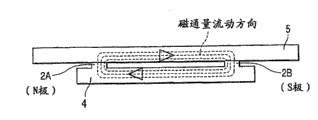
Fig. 2 is an end view, demonstrates the position relation between permanent magnet 1, extraction part 2A and 2B and the moving component 5.
In the vibration wave motor (linear oscillator ripple motor) according to first embodiment, the extraction part 2A that is located on the permanent magnet 1 contacts with moving component 5 with 2B.Therefore, form following magnetic flux closed magnetic circuit.Magnetic flux from extraction part 2A (the N utmost point) flows to moving component 5 along the direction identical with the direction of motion of moving component 5, and enters extraction part 2B (the S utmost point).Then, magnetic flux flows to the N utmost point from the S utmost point of permanent magnet 1, and turns back to extraction part 2A (the N utmost point).
When forming the magnetic flux closed magnetic circuit, magnetic flux is assembled on the contact surface between each and the moving component 5 at extraction part 2A and 2B.Therefore, moving component 5 can be pressed on extraction part 2A and the 2B effectively.
Magnetic flux is assembled on described contact surface constantly, and flows through moving component 5, so magnetic resistance becomes constant.Therefore, at moving component 5 during, even under situation about changing with extraction part 2A and 2B position contacting, also can not produce shown in Fig. 7 B along the restoring force of the direction of motion with respect to elastic vibration parts 4 motion.
The flow direction of magnetic flux is consistent with the direction of motion of moving component 5, so magnetic resistance even become minimum along the direction vertical with the direction of motion of moving component 5.At moving component 5 when the direction vertical with the direction of motion moved, the variation that exists magnetic resistance to increase.Therefore, produce calibrated force, to prevent lateral deviation with respect to the direction of motion to this variation.Therefore, needn't be provided for the guide of moving component 5, the result can reduce amount of parts.
Make moving component 5 along in movement travel, all equating at least with contact width W with the width of the vertical direction of the direction of motion of moving component 5 and the width of each extraction part 2A and 2B.Therefore, when the moving component 5 lateral run-out directions of motion, it is remarkable that the variation of magnetic resistance becomes.Therefore, can improve the response of calibrated force to produce high-precision magnetic guiding.
The permanent magnet 1 that is used as the part of elastic vibration parts 4 also can adopt the sintered magnet of making by powder sintering method to constitute.But sintered magnet breaks easily or is cracked, thereby the percent defective when machining or assembling is higher.Therefore in addition, the elastic limit of sintered magnet is lower, has such defective, promptly when sintered magnet during with big displacement deformation generation break.
Therefore, the permanent magnet 1 of this embodiment adopts iron-chromium-cobalt (Fe-Cr-Co) casting magnet to constitute.Though iron-chromium-cobalt casting magnet is a kind of magnet, it has the quality identical with ordinary metallic material, can carry out cut or plastic working, and have high elastic limit.Can on Fe-Cr-Co casting magnet, form extraction part 2A and 2B by etching etc., thereby be fit to use Fe-Cr-Co casting magnet as permanent magnet 1.
Also a kind of method is adopted in expectation, this method adopts the parts of being made by soft magnetic member (for example ferroalloy) different with permanent magnet 1 to form extraction part 2A and 2B, and by bonding etc. formed extraction part 2A and 2B is connected on the flat permanent magnet 1.But in view of in the arrangement precision of extraction part 2A and 2B and the reliability aspect the adhesive strength thereof, this is unsatisfactory.
In the first embodiment, having described wherein, permanent magnet 1 is subjected to the bipolar magnetized example of single face.As shown in Figure 3, the rear magnetic yoke of being made by soft magnetic member 6 can be by for example being adhesively fixed between permanent magnet 1 and the piezoelectric element 3 (not having shown in Figure 3), and permanent magnet 1 can magnetize for vertical bipolar.Therefore, form the magnetic flux closed magnetic circuit of the rear magnetic yoke 6 of flowing through, thus with compare in the structure shown in Fig. 2, between each of moving component 5 and extraction part 2A and 2B, produce stronger sucking action.
Any parts of being made by soft magnetic member all are enough to as moving component 5.The magnetic steel plate that employing is widely used in electromagnetic motor or electromagnetic transformers is being effective aspect magnetic efficiency and the cost in particular for the grain-orientated magnetic steel sheet of linear oscillator ripple motor.
According to the explanation of first embodiment, supposed that moving component 5 is with respect to 4 motions of elastic vibration parts.Also can adopt the structure of elastic vibration parts 4 wherein with respect to moving component 5 motions.
In the first embodiment, permanent magnet 1 and piezoelectric element 3 each all have plate-like shape.In addition, for example, moving component can be bonded on the spherical member to obtain bowed shape, perhaps can with permanent magnet and piezoelectric element further thickening to obtain cylindrical shape.
In the first embodiment, permanent magnet 1 and piezoelectric element 3 for example interfix by bonding.But, preferably, piezoelectric element can be clipped between permanent magnet 1 and the different parts with fixed permanent magnet and piezoelectric element.
Second embodiment
Fig. 4 A and 4B are respectively a plane graph and an end view, demonstrate the structure according to the elastic vibration parts of the vibration wave motor of second embodiment of the invention.This vibration wave motor is a whirling vibration ripple motor.
The discoid permanent magnet of Reference numeral 11 expressions, the discoid piezoelectric element of 13 expressions.Discoid elastic vibration parts 14 comprise disc permanent magnet 11 and disc piezoelectric element 13.
Disc permanent magnet 11 is subjected to the magnetization of single face four utmost points.Disc permanent magnet 11 be subjected to that the circumferencial direction along disc permanent magnet 11 is provided with a plurality of extraction part 12A, 12B, 12C and 12D on the extremely magnetized surface of single face four, and disc piezoelectric element 13 is by for example being adhesively fixed on its another surface.Extraction part 12A is geomagnetic into the N utmost point, and is fixed on the N utmost point side of disc permanent magnet 11.Extraction part 12B is geomagnetic into the S utmost point and is fixed on the S utmost point side of disc permanent magnet 11.Extraction part 12C is geomagnetic into the N utmost point and is fixed on the N utmost point side of disc permanent magnet 11.Extraction part 12D is geomagnetic into the S utmost point and is fixed on the S utmost point side of disc permanent magnet 11.
This disc piezoelectric element 13 with a surface that is bonded in its another surface opposite on the disc permanent magnet 11 on be formed with the electrode pattern (not shown) that is used for multiple vibration mode excitation disc piezoelectric element 13.When high-frequency alternating voltage being applied on this electrode pattern from external power source (not shown), disc piezoelectric element 13 vibrates with multiple vibration mode, so that extraction part 12A, 12B, 12C and 12D produce elliptic motion.
Fig. 5 A and 5B are respectively a plane graph and an end view, demonstrate the structure according to the rotating moving part of the vibration wave motor of second embodiment of the invention.
In Fig. 5 A and 5B, Reference numeral 15 its raw materials of expression are the rotating moving part of non-orientated magnetic steel plate.It is not preferred that rotating moving part 15 adopts grain-orientated magnetic steel sheet.As shown in Figure 6, rotating moving part 15 is according to being arranged on the disc elastic vibration parts 14 with mode that extraction part 12A, 12B, 12C contact with 12D.At least in movement travel, make rotating moving part 15 equal the width (along the width of the radial direction of disc permanent magnet 11) of extraction part 12A, 12B, 12C and 12D along the width of the direction vertical (radial direction) with the circumferencial direction of rotating moving part 15.That is to say, be contact width W with each width setup.
Fig. 6 is the end view that launches along circumferencial direction, demonstrates the position relation between disc permanent magnet 11, extraction part 12A, 12B, 12C and 12D and the rotating moving part 15.
In the vibration wave motor (whirling vibration ripple motor) according to second embodiment, the extraction part 12A, 12B, 12C and the 12D that are located on the disc permanent magnet 11 contact with rotating moving part 15.Therefore, form following magnetic flux closed magnetic circuit.Magnetic flux from extraction part 12A (the N utmost point) and extraction part 12C (the N utmost point) flows to rotating moving part 15 along the direction identical with the direction of motion of rotating moving part 15, and enters into extraction part 12D (the S utmost point) and extraction part 12B (the S utmost point) each.Then, magnetic flux flows to the N utmost point from the S utmost point of disc permanent magnet 11, and turns back to extraction part 12A (the N utmost point) and extraction part 12C (the N utmost point) each.
When forming the magnetic flux closed magnetic circuit, magnetic flux is assembled on the contact surface between each and the rotating moving part 15 at extraction part 12A, 12B, 12C and 12D.Therefore, can effectively rotational motion parts 15 be pressed on extraction part 12A, 12B, 12C and the 12D.
Magnetic flux is assembled and the moving component 5 of flowing through on contact surface constantly, so magnetic resistance becomes constant.Therefore, when moving component 15 moves with respect to elastic vibration parts 14, even the restoring force F along the direction of motion can not produce under the situation that the contact position with extraction part 12A, 12B, 12C and 12D changes yet shown in Fig. 7 B.
The flow direction of magnetic flux is consistent with the direction of rotation (direction of motion) of rotating moving part 15, so magnetic resistance even also become minimum along the radial direction with rotating moving part 15.When radial direction moves, exist magnetic resistance to increase such variation at rotating moving part 15.Therefore, produce calibrated force, to prevent lateral deviation with respect to direction of rotation to this variation.Therefore, needn't be provided for the guide of rotating moving part 15, the result can reduce amount of parts.
Rotating moving part 15 is all equated with contact width W in movement travel at least along the width of the radial direction of rotating moving part 15 and the width of each extraction part 12A, 12B, 12C and 12D.Therefore, when rotating moving part 15 lateral run-out direction of rotation, it is remarkable that the variation of magnetic resistance becomes.Therefore, can improve the response of calibrated force to obtain high-precision magnetic guiding.
Owing to can under the situation that does not break away from the spirit and scope of the present invention, make many visibly different embodiments to it, thus it being understood that and the invention is not restricted to its specific embodiments, and only be defined by the following claims.
Claims (8)
1. vibration wave motor comprises:
The elastic vibration parts, it comprises permanent magnet fixed to one another and energy converting between mechanical element;
Be located at first extraction part and the second extraction part on the elastic vibration parts; And
Moving component, thus it is pressed in described first extraction part and partly goes up with it with second extraction and contact,
Wherein the magnetic flux from first extraction part flows to moving component, and flow to the second extraction part, and turn back to the first extraction part, thus the closed magnetic circuit of formation magnetic flux; And
The flow direction of the magnetic flux of process moving component is consistent with the direction of motion of moving component.
2. vibration wave motor as claimed in claim 1, wherein said elastic vibration parts produce the vibration corresponding with a plurality of vibration modes, thereby by making described first extraction part and second extraction partly produce elliptic motion synthesizing of these vibrations.
3. vibration wave motor as claimed in claim 1, wherein, contact width along the direction vertical with the direction of motion of moving component between moving component and described first extraction part and second extraction part is equal to each other, and flux concentration flows through moving component and described first extraction part and second extraction magnetic circuit partly thereby form wherein.
4. vibration wave motor as claimed in claim 1, wherein, described first extraction part and second extraction partly are geomagnetic into the opposite polarity with alternate.
5. vibration wave motor as claimed in claim 1, wherein:
Described moving component is made by grain-orientated magnetic steel sheet; And
The direction of motion of moving component and easy magnetization axis direction one are shown and are carried out Linear Driving.
6. vibration wave motor as claimed in claim 1, wherein:
Described moving component is made by non-orientated magnetic steel plate;
In described moving component and the elastic vibration parts each forms disc-shape; And
By the elastic vibration parts described moving component is rotated.
7. vibration wave motor as claimed in claim 1, wherein:
The permanent magnet that is included in the described elastic vibration parts is subjected to the bipolar magnetization of single face; And
Described first extraction part and second extraction part are fixed on the permanent magnet corresponding to its magnetic pole.
8. vibration wave motor as claimed in claim 1 also comprises:
Soft magnetic member is between its permanent magnet and energy converting between mechanical element in being included in the elastic vibration parts;
Wherein, described permanent magnet is subjected to bipolar magnetization along thickness direction; And
The closed magnetic circuit of described magnetic flux forms by described first extraction part and second extraction part and permanent magnet and is connected between soft magnetic member and the moving component.
Applications Claiming Priority (2)
| Application Number | Priority Date | Filing Date | Title |
|---|---|---|---|
| JP2005159856 | 2005-05-31 | ||
| JP2005159856A JP4756916B2 (en) | 2005-05-31 | 2005-05-31 | Vibration wave motor |
Publications (2)
| Publication Number | Publication Date |
|---|---|
| CN1874135A CN1874135A (en) | 2006-12-06 |
| CN100553104C true CN100553104C (en) | 2009-10-21 |
Family
ID=37462440
Family Applications (1)
| Application Number | Title | Priority Date | Filing Date |
|---|---|---|---|
| CNB2006100877305A Expired - Fee Related CN100553104C (en) | 2005-05-31 | 2006-05-31 | Vibration wave motor |
Country Status (3)
| Country | Link |
|---|---|
| US (1) | US7425770B2 (en) |
| JP (1) | JP4756916B2 (en) |
| CN (1) | CN100553104C (en) |
Families Citing this family (16)
| Publication number | Priority date | Publication date | Assignee | Title |
|---|---|---|---|---|
| JP2010532150A (en) * | 2007-06-29 | 2010-09-30 | スティヒティング・イメック・ネーデルラント | Moving permanent magnet based electromagnetic energy scavenger |
| US7969065B2 (en) | 2008-09-09 | 2011-06-28 | Canon Kabushiki Kaisha | Vibration wave driving device |
| US9696803B2 (en) | 2009-03-12 | 2017-07-04 | Immersion Corporation | Systems and methods for friction displays and additional haptic effects |
| US9874935B2 (en) * | 2009-03-12 | 2018-01-23 | Immersion Corporation | Systems and methods for a texture engine |
| US9746923B2 (en) | 2009-03-12 | 2017-08-29 | Immersion Corporation | Systems and methods for providing features in a friction display wherein a haptic effect is configured to vary the coefficient of friction |
| US9927873B2 (en) | 2009-03-12 | 2018-03-27 | Immersion Corporation | Systems and methods for using textures in graphical user interface widgets |
| US10564721B2 (en) * | 2009-03-12 | 2020-02-18 | Immersion Corporation | Systems and methods for using multiple actuators to realize textures |
| US10007340B2 (en) | 2009-03-12 | 2018-06-26 | Immersion Corporation | Systems and methods for interfaces featuring surface-based haptic effects |
| US20110115709A1 (en) * | 2009-11-17 | 2011-05-19 | Immersion Corporation | Systems And Methods For Increasing Haptic Bandwidth In An Electronic Device |
| WO2011062910A1 (en) * | 2009-11-17 | 2011-05-26 | Immersion Corporation | Systems and methods for a friction rotary device for haptic feedback |
| JP5656429B2 (en) * | 2010-03-23 | 2015-01-21 | キヤノン株式会社 | Vibration wave drive |
| US8643252B2 (en) | 2010-05-11 | 2014-02-04 | Canon Kabushiki Kaisha | Vibration wave actuator |
| WO2014063223A1 (en) * | 2012-10-26 | 2014-05-01 | Sullivan William Paul | System and apparatus for generating electricity from motion of fluid |
| JP6249203B2 (en) * | 2013-05-17 | 2017-12-20 | パナソニックIpマネジメント株式会社 | Power generation vibration sensor, tire and electric device using the same |
| JP6876960B2 (en) * | 2017-03-29 | 2021-05-26 | パナソニックIpマネジメント株式会社 | Power generation device and input device equipped with it |
| CN110445299B (en) * | 2019-08-21 | 2021-11-30 | 国网江苏省电力有限公司泰州供电分公司 | Disk type mobile phone vibrating motor |
Citations (5)
| Publication number | Priority date | Publication date | Assignee | Title |
|---|---|---|---|---|
| US4453103A (en) * | 1982-04-16 | 1984-06-05 | Kievsky Politekhnichesky Institut | Piezoelectric motor |
| US5128580A (en) * | 1990-04-02 | 1992-07-07 | Canon Kabushiki Kaisha | Vibration wave driven motor |
| US5359251A (en) * | 1992-01-29 | 1994-10-25 | Canon Kabushiki Kaisha | Vibration driven actuator |
| US5952766A (en) * | 1985-08-05 | 1999-09-14 | Canon Kabushiki Kaisha | Vibration wave motor |
| CN1617366A (en) * | 2003-11-13 | 2005-05-18 | 佳能株式会社 | Multilayer piezoelectric element and vibration-wave drive device |
Family Cites Families (72)
| Publication number | Priority date | Publication date | Assignee | Title |
|---|---|---|---|---|
| US3394275A (en) * | 1966-02-09 | 1968-07-23 | Fed Electronics Inc | Vibration transducers |
| CA1208269A (en) * | 1982-02-25 | 1986-07-22 | Toshiiku Sashida | Motor device utilizing ultrasonic oscillation |
| JPS59185179A (en) | 1983-04-04 | 1984-10-20 | Canon Inc | Supersonic motor |
| US4752711A (en) * | 1985-03-29 | 1988-06-21 | Canon Kabushiki Kaisha | Vibration wave motor |
| US4728843A (en) * | 1985-11-11 | 1988-03-01 | Taga Electric Co., Ltd. | Ultrasonic vibrator and drive control method thereof |
| US4703214A (en) * | 1985-11-27 | 1987-10-27 | Taga Electric Co., Ltd. | Ultrasonic vibrator and its drive control method |
| JP2632811B2 (en) * | 1986-08-29 | 1997-07-23 | キヤノン株式会社 | Vibration drive motor |
| US5099166A (en) * | 1987-01-12 | 1992-03-24 | Canon Kabushiki Kaisha | Vibration wave driven motor |
| US4868446A (en) * | 1987-01-22 | 1989-09-19 | Hitachi Maxell, Ltd. | Piezoelectric revolving resonator and ultrasonic motor |
| JPS63294279A (en) * | 1987-05-25 | 1988-11-30 | Hiroshi Shimizu | Piezoelectric driving device |
| EP0356591B1 (en) * | 1988-09-02 | 1995-11-15 | Honda Electronic Co., Ltd. | Ultrasonic driving devices |
| DE69030827T2 (en) * | 1989-02-14 | 1998-01-15 | Canon Kk | Vibration wave motor |
| US5039899A (en) * | 1989-02-28 | 1991-08-13 | Brother Kogyo Kabushiki Kaisha | Piezoelectric transducer |
| JP2935504B2 (en) * | 1989-07-05 | 1999-08-16 | キヤノン株式会社 | motor |
| US5191688A (en) * | 1989-07-27 | 1993-03-09 | Olympus Optical Co., Ltd. | Method for producing a superior longitudinal vibrator |
| US5136200A (en) * | 1989-07-27 | 1992-08-04 | Olympus Optical Co., Ltd. | Ultransonic motor |
| US5006749A (en) * | 1989-10-03 | 1991-04-09 | Regents Of The University Of California | Method and apparatus for using ultrasonic energy for moving microminiature elements |
| JPH03183376A (en) * | 1989-12-08 | 1991-08-09 | Canon Inc | Oscillation wave motor |
| JP2996477B2 (en) * | 1990-02-05 | 1999-12-27 | キヤノン株式会社 | Vibration wave drive |
| JPH0488890A (en) | 1990-07-27 | 1992-03-23 | Fujitsu Ltd | Ultrasonic motor |
| JP2879955B2 (en) * | 1990-08-03 | 1999-04-05 | キヤノン株式会社 | Vibration wave drive |
| JP2925272B2 (en) * | 1990-08-31 | 1999-07-28 | キヤノン株式会社 | Vibration wave motor |
| US5610468A (en) * | 1990-10-22 | 1997-03-11 | Seiko Epson Corporation | Ultrasonic step motor |
| JPH0523796U (en) * | 1991-09-03 | 1993-03-26 | 山武ハネウエル株式会社 | Surface wave motor |
| JP2803939B2 (en) * | 1992-01-23 | 1998-09-24 | キヤノン株式会社 | Vibration wave device |
| US5410204A (en) * | 1992-02-28 | 1995-04-25 | Olympus Optical Co. Ltd. | Ultrasonic oscillator |
| JP3107933B2 (en) * | 1992-12-03 | 2000-11-13 | キヤノン株式会社 | Vibration wave driving device and device provided with vibration wave driving device |
| JPH06292374A (en) | 1993-04-05 | 1994-10-18 | Rion Denshi Kk | Piezoelectric actuator |
| JP3363510B2 (en) | 1993-04-16 | 2003-01-08 | キヤノン株式会社 | Vibration wave drive |
| JP3059031B2 (en) * | 1993-09-22 | 2000-07-04 | キヤノン株式会社 | Vibration wave drive device and device provided with vibration wave drive device |
| JP3279020B2 (en) | 1993-11-15 | 2002-04-30 | 株式会社ニコン | Ultrasonic motor |
| JP3279021B2 (en) | 1993-11-15 | 2002-04-30 | 株式会社ニコン | Ultrasonic motor and its manufacturing method |
| EP0661764B1 (en) * | 1993-12-27 | 1999-03-10 | Canon Kabushiki Kaisha | Vibration wave actuator |
| DE69507857T2 (en) * | 1994-07-05 | 1999-08-19 | Nikon Corp | Vibration driven motor |
| JP3402816B2 (en) * | 1994-12-22 | 2003-05-06 | キヤノン株式会社 | Ultrasonic motor drive circuit |
| US5665918A (en) * | 1994-12-26 | 1997-09-09 | Canon Kabushiki Kaisha | Linear vibration actuator utilizing combined bending and longitudinal vibration modes |
| JP3432321B2 (en) * | 1995-01-31 | 2003-08-04 | 太平洋セメント株式会社 | Multilayer ceramic piezoelectric element |
| JPH08280185A (en) * | 1995-04-07 | 1996-10-22 | Nikon Corp | Ultrasonic actuator |
| US5814919A (en) * | 1995-04-28 | 1998-09-29 | Canon Kabushiki Kaisha | Electro-mechanical energy conversion element and a vibration wave actuator using the electro-mechanical energy conversion element |
| JPH099651A (en) * | 1995-06-15 | 1997-01-10 | Nikon Corp | Ultrasonic actuator |
| JPH09121570A (en) * | 1995-08-22 | 1997-05-06 | Nikon Corp | Vibration actuator |
| JPH09219980A (en) * | 1995-12-04 | 1997-08-19 | Nikon Corp | Free multidegree drive device |
| FR2743457B1 (en) * | 1996-01-04 | 1998-03-06 | Figest Bv | PROGRESSIVE WAVE PIEZOELECTRIC MOTOR |
| US5912525A (en) * | 1996-03-21 | 1999-06-15 | Nikon Corporation | Vibration actuator |
| WO1997036365A1 (en) * | 1996-03-26 | 1997-10-02 | Stefan Johansson | An actuator motor and a method for fabrication of such an actuator |
| JP4026885B2 (en) * | 1997-05-16 | 2007-12-26 | キヤノン株式会社 | Piezoelectric element and vibration type driving device |
| JP3184117B2 (en) * | 1997-05-23 | 2001-07-09 | セイコーインスツルメンツ株式会社 | Ultrasonic motor and electronic device with ultrasonic motor |
| US6404104B1 (en) * | 1997-11-27 | 2002-06-11 | Canon Kabushiki Kaisha | Vibration type actuator and vibration type driving apparatus |
| US6252333B1 (en) * | 1998-02-20 | 2001-06-26 | Seiko Instruments Inc. | Stage utilizing ultrasonic motor and electronic equipment and printer utilizing the stage |
| JPH11285279A (en) | 1998-03-30 | 1999-10-15 | Tdk Corp | Acoustic wave actuator |
| US6198201B1 (en) * | 1998-06-03 | 2001-03-06 | Canon Kabushiki Kaisha | Vibration wave apparatus |
| JP4328412B2 (en) * | 1999-05-14 | 2009-09-09 | キヤノン株式会社 | Vibration type actuator and vibration type drive device |
| JP3526298B2 (en) * | 2001-01-22 | 2004-05-10 | キヤノン株式会社 | Vibrating body and vibration wave driving device |
| US6930436B2 (en) * | 2001-01-22 | 2005-08-16 | Canon Kabushiki Kaisha | Vibration element and vibration wave driving apparatus |
| JP4726167B2 (en) * | 2001-03-12 | 2011-07-20 | キヤノン株式会社 | Vibration wave drive |
| JP4027090B2 (en) * | 2001-12-27 | 2007-12-26 | キヤノン株式会社 | Vibration body and vibration wave drive device |
| JP2004215389A (en) * | 2002-12-27 | 2004-07-29 | Victor Co Of Japan Ltd | Surface acoustic wave actuator and deflector employing surface acoustic wave actuator |
| JP4095913B2 (en) | 2003-02-26 | 2008-06-04 | 株式会社日立ハイテクノロジーズ | High precision micro movement device |
| JP4328113B2 (en) * | 2003-03-13 | 2009-09-09 | オリンパス株式会社 | Ultrasonic motor |
| JP4086690B2 (en) * | 2003-03-19 | 2008-05-14 | キヤノン株式会社 | manipulator |
| US7187104B2 (en) * | 2003-03-28 | 2007-03-06 | Canon Kabushiki Kaisha | Vibration-type driving device, control apparatus for controlling the driving of the vibration-type driving device, and electronic equipment having the vibration-type driving device and the control apparatus |
| US7148605B2 (en) * | 2003-12-15 | 2006-12-12 | Palo Alto Research Center, Incorporated | Biaxial piezoelectric motor |
| JP4576154B2 (en) * | 2004-05-13 | 2010-11-04 | オリンパス株式会社 | Ultrasonic motor |
| DE102004024656A1 (en) * | 2004-05-18 | 2005-12-08 | Physik Instrumente (Pi) Gmbh & Co. Kg | Piezoelectric ultrasonic motor |
| KR100631884B1 (en) * | 2004-11-24 | 2006-10-09 | 삼성전기주식회사 | Flat Plate Piezoelectric Ultrasonic Motor |
| JP4794901B2 (en) * | 2005-05-09 | 2011-10-19 | キヤノン株式会社 | Driving system for vibration type actuator and driving method thereof |
| JP2007089246A (en) * | 2005-09-20 | 2007-04-05 | Konica Minolta Opto Inc | Driver and lens barrel, and imaging apparatus |
| JP4838567B2 (en) * | 2005-10-26 | 2011-12-14 | キヤノン株式会社 | Frequency control circuit, motor drive device, frequency control method, motor drive device control method, and program for causing computer to execute control method |
| JP2008035685A (en) * | 2006-02-13 | 2008-02-14 | Nikon Corp | Motor, lens barrel, camera system, and manufacturing method of motor |
| US7471030B2 (en) * | 2006-03-08 | 2008-12-30 | Dynamic Structures And Materials, Llc | Spring biasing locking mechanism for step and repeat motors |
| JP2008067539A (en) * | 2006-09-08 | 2008-03-21 | Konica Minolta Opto Inc | Ultrasonic actuator and method of manufacturing its vibrator |
| JP2008136318A (en) * | 2006-11-29 | 2008-06-12 | Olympus Corp | Ultrasonic motor and microscope stage |
-
2005
- 2005-05-31 JP JP2005159856A patent/JP4756916B2/en not_active Expired - Fee Related
-
2006
- 2006-04-25 US US11/410,209 patent/US7425770B2/en not_active Expired - Fee Related
- 2006-05-31 CN CNB2006100877305A patent/CN100553104C/en not_active Expired - Fee Related
Patent Citations (5)
| Publication number | Priority date | Publication date | Assignee | Title |
|---|---|---|---|---|
| US4453103A (en) * | 1982-04-16 | 1984-06-05 | Kievsky Politekhnichesky Institut | Piezoelectric motor |
| US5952766A (en) * | 1985-08-05 | 1999-09-14 | Canon Kabushiki Kaisha | Vibration wave motor |
| US5128580A (en) * | 1990-04-02 | 1992-07-07 | Canon Kabushiki Kaisha | Vibration wave driven motor |
| US5359251A (en) * | 1992-01-29 | 1994-10-25 | Canon Kabushiki Kaisha | Vibration driven actuator |
| CN1617366A (en) * | 2003-11-13 | 2005-05-18 | 佳能株式会社 | Multilayer piezoelectric element and vibration-wave drive device |
Also Published As
| Publication number | Publication date |
|---|---|
| US20060267416A1 (en) | 2006-11-30 |
| US7425770B2 (en) | 2008-09-16 |
| JP4756916B2 (en) | 2011-08-24 |
| CN1874135A (en) | 2006-12-06 |
| JP2006340443A (en) | 2006-12-14 |
Similar Documents
| Publication | Publication Date | Title |
|---|---|---|
| CN100553104C (en) | Vibration wave motor | |
| JP7173119B2 (en) | permanent magnet piece | |
| EP2375098A2 (en) | Magnetic spring system in a resonant motor | |
| JP2007288828A (en) | Inertia-driven actuator | |
| JP2011217595A (en) | Vibration wave driving apparatus and method for manufacturing vibrating body thereof | |
| JP5185640B2 (en) | Inertial drive actuator | |
| CN104467524A (en) | Working method of plate type linear piezoelectric motor based on in-plane mode | |
| CN109039146B (en) | Inertial stick-slip driving trans-scale precision motion platform | |
| JP2011200053A (en) | Vibration wave driver | |
| CN103684039A (en) | Magnetostrictive inertial impact driver | |
| CN102118118B (en) | Linear type ultrasonic micromotor | |
| CN102005964B (en) | Magnetostriction type inertial impact micro linear motor | |
| CN105162354A (en) | Giant magnetostrictive material-based rocking head type micromotor | |
| CN104716864B (en) | Linear piezoelectric motor of inertia type middle-sized structure and control method thereof | |
| CN203608110U (en) | Magnetostriction-type inertial impact driver | |
| JP4602888B2 (en) | Vibration generator | |
| JP5851210B2 (en) | Inertial drive actuator | |
| JP5349768B2 (en) | Vibration wave drive | |
| Ueno et al. | Miniature magnetostrictive linear actuator based on smooth impact drive mechanism | |
| CN203608111U (en) | Magnetostriction-type inertial impact rotation driver | |
| CN103684040A (en) | Magnetostrictive inertial impact rotating driver | |
| CN213637443U (en) | Galfenol alloy driven double-inertia impact type precise stepping micro linear motor | |
| JP5003992B2 (en) | Cylindrical linear motor | |
| JP2010213537A (en) | Actuator and positioning device using it | |
| KR101264259B1 (en) | An Apparatus and Method of precise alignment for bonding jig |
Legal Events
| Date | Code | Title | Description |
|---|---|---|---|
| C06 | Publication | ||
| PB01 | Publication | ||
| C10 | Entry into substantive examination | ||
| SE01 | Entry into force of request for substantive examination | ||
| C14 | Grant of patent or utility model | ||
| GR01 | Patent grant | ||
| CF01 | Termination of patent right due to non-payment of annual fee |
Granted publication date: 20091021 |
|
| CF01 | Termination of patent right due to non-payment of annual fee |