CN100523709C - Portable coordinate measurement machine with articulated jib - Google Patents
Portable coordinate measurement machine with articulated jib Download PDFInfo
- Publication number
- CN100523709C CN100523709C CNB038036851A CN03803685A CN100523709C CN 100523709 C CN100523709 C CN 100523709C CN B038036851 A CNB038036851 A CN B038036851A CN 03803685 A CN03803685 A CN 03803685A CN 100523709 C CN100523709 C CN 100523709C
- Authority
- CN
- China
- Prior art keywords
- measuring machine
- coordinate measuring
- joint
- bearing
- housing
- Prior art date
- Legal status (The legal status is an assumption and is not a legal conclusion. Google has not performed a legal analysis and makes no representation as to the accuracy of the status listed.)
- Expired - Fee Related
Links
Images


Classifications
-
- G—PHYSICS
- G01—MEASURING; TESTING
- G01B—MEASURING LENGTH, THICKNESS OR SIMILAR LINEAR DIMENSIONS; MEASURING ANGLES; MEASURING AREAS; MEASURING IRREGULARITIES OF SURFACES OR CONTOURS
- G01B11/00—Measuring arrangements characterised by the use of optical techniques
- G01B11/24—Measuring arrangements characterised by the use of optical techniques for measuring contours or curvatures
- G01B11/25—Measuring arrangements characterised by the use of optical techniques for measuring contours or curvatures by projecting a pattern, e.g. one or more lines, moiré fringes on the object
-
- B—PERFORMING OPERATIONS; TRANSPORTING
- B23—MACHINE TOOLS; METAL-WORKING NOT OTHERWISE PROVIDED FOR
- B23Q—DETAILS, COMPONENTS, OR ACCESSORIES FOR MACHINE TOOLS, e.g. ARRANGEMENTS FOR COPYING OR CONTROLLING; MACHINE TOOLS IN GENERAL CHARACTERISED BY THE CONSTRUCTION OF PARTICULAR DETAILS OR COMPONENTS; COMBINATIONS OR ASSOCIATIONS OF METAL-WORKING MACHINES, NOT DIRECTED TO A PARTICULAR RESULT
- B23Q35/00—Control systems or devices for copying directly from a pattern or a master model; Devices for use in copying manually
- B23Q35/04—Control systems or devices for copying directly from a pattern or a master model; Devices for use in copying manually using a feeler or the like travelling along the outline of the pattern, model or drawing; Feelers, patterns, or models therefor
-
- B—PERFORMING OPERATIONS; TRANSPORTING
- B25—HAND TOOLS; PORTABLE POWER-DRIVEN TOOLS; MANIPULATORS
- B25J—MANIPULATORS; CHAMBERS PROVIDED WITH MANIPULATION DEVICES
- B25J17/00—Joints
- B25J17/02—Wrist joints
- B25J17/0241—One-dimensional joints
- B25J17/025—One-dimensional joints mounted in series
-
- B—PERFORMING OPERATIONS; TRANSPORTING
- B25—HAND TOOLS; PORTABLE POWER-DRIVEN TOOLS; MANIPULATORS
- B25J—MANIPULATORS; CHAMBERS PROVIDED WITH MANIPULATION DEVICES
- B25J19/00—Accessories fitted to manipulators, e.g. for monitoring, for viewing; Safety devices combined with or specially adapted for use in connection with manipulators
- B25J19/0008—Balancing devices
- B25J19/0016—Balancing devices using springs
-
- B—PERFORMING OPERATIONS; TRANSPORTING
- B25—HAND TOOLS; PORTABLE POWER-DRIVEN TOOLS; MANIPULATORS
- B25J—MANIPULATORS; CHAMBERS PROVIDED WITH MANIPULATION DEVICES
- B25J19/00—Accessories fitted to manipulators, e.g. for monitoring, for viewing; Safety devices combined with or specially adapted for use in connection with manipulators
- B25J19/0091—Shock absorbers
-
- B—PERFORMING OPERATIONS; TRANSPORTING
- B25—HAND TOOLS; PORTABLE POWER-DRIVEN TOOLS; MANIPULATORS
- B25J—MANIPULATORS; CHAMBERS PROVIDED WITH MANIPULATION DEVICES
- B25J9/00—Programme-controlled manipulators
- B25J9/0009—Constructional details, e.g. manipulator supports, bases
- B25J9/0012—Constructional details, e.g. manipulator supports, bases making use of synthetic construction materials, e.g. plastics, composites
-
- B—PERFORMING OPERATIONS; TRANSPORTING
- B25—HAND TOOLS; PORTABLE POWER-DRIVEN TOOLS; MANIPULATORS
- B25J—MANIPULATORS; CHAMBERS PROVIDED WITH MANIPULATION DEVICES
- B25J9/00—Programme-controlled manipulators
- B25J9/02—Programme-controlled manipulators characterised by movement of the arms, e.g. cartesian coordinate type
- B25J9/023—Cartesian coordinate type
-
- B—PERFORMING OPERATIONS; TRANSPORTING
- B25—HAND TOOLS; PORTABLE POWER-DRIVEN TOOLS; MANIPULATORS
- B25J—MANIPULATORS; CHAMBERS PROVIDED WITH MANIPULATION DEVICES
- B25J9/00—Programme-controlled manipulators
- B25J9/06—Programme-controlled manipulators characterised by multi-articulated arms
-
- B—PERFORMING OPERATIONS; TRANSPORTING
- B25—HAND TOOLS; PORTABLE POWER-DRIVEN TOOLS; MANIPULATORS
- B25J—MANIPULATORS; CHAMBERS PROVIDED WITH MANIPULATION DEVICES
- B25J9/00—Programme-controlled manipulators
- B25J9/16—Programme controls
- B25J9/1602—Programme controls characterised by the control system, structure, architecture
-
- G—PHYSICS
- G01—MEASURING; TESTING
- G01B—MEASURING LENGTH, THICKNESS OR SIMILAR LINEAR DIMENSIONS; MEASURING ANGLES; MEASURING AREAS; MEASURING IRREGULARITIES OF SURFACES OR CONTOURS
- G01B11/00—Measuring arrangements characterised by the use of optical techniques
- G01B11/002—Measuring arrangements characterised by the use of optical techniques for measuring two or more coordinates
- G01B11/005—Measuring arrangements characterised by the use of optical techniques for measuring two or more coordinates coordinate measuring machines
-
- G—PHYSICS
- G01—MEASURING; TESTING
- G01B—MEASURING LENGTH, THICKNESS OR SIMILAR LINEAR DIMENSIONS; MEASURING ANGLES; MEASURING AREAS; MEASURING IRREGULARITIES OF SURFACES OR CONTOURS
- G01B11/00—Measuring arrangements characterised by the use of optical techniques
- G01B11/02—Measuring arrangements characterised by the use of optical techniques for measuring length, width or thickness
- G01B11/03—Measuring arrangements characterised by the use of optical techniques for measuring length, width or thickness by measuring coordinates of points
-
- G—PHYSICS
- G01—MEASURING; TESTING
- G01B—MEASURING LENGTH, THICKNESS OR SIMILAR LINEAR DIMENSIONS; MEASURING ANGLES; MEASURING AREAS; MEASURING IRREGULARITIES OF SURFACES OR CONTOURS
- G01B21/00—Measuring arrangements or details thereof, where the measuring technique is not covered by the other groups of this subclass, unspecified or not relevant
- G01B21/02—Measuring arrangements or details thereof, where the measuring technique is not covered by the other groups of this subclass, unspecified or not relevant for measuring length, width, or thickness
- G01B21/04—Measuring arrangements or details thereof, where the measuring technique is not covered by the other groups of this subclass, unspecified or not relevant for measuring length, width, or thickness by measuring coordinates of points
- G01B21/045—Correction of measurements
-
- G—PHYSICS
- G01—MEASURING; TESTING
- G01B—MEASURING LENGTH, THICKNESS OR SIMILAR LINEAR DIMENSIONS; MEASURING ANGLES; MEASURING AREAS; MEASURING IRREGULARITIES OF SURFACES OR CONTOURS
- G01B5/00—Measuring arrangements characterised by the use of mechanical techniques
- G01B5/004—Measuring arrangements characterised by the use of mechanical techniques for measuring coordinates of points
- G01B5/008—Measuring arrangements characterised by the use of mechanical techniques for measuring coordinates of points using coordinate measuring machines
-
- G—PHYSICS
- G06—COMPUTING; CALCULATING OR COUNTING
- G06T—IMAGE DATA PROCESSING OR GENERATION, IN GENERAL
- G06T7/00—Image analysis
- G06T7/50—Depth or shape recovery
- G06T7/521—Depth or shape recovery from laser ranging, e.g. using interferometry; from the projection of structured light
-
- Y—GENERAL TAGGING OF NEW TECHNOLOGICAL DEVELOPMENTS; GENERAL TAGGING OF CROSS-SECTIONAL TECHNOLOGIES SPANNING OVER SEVERAL SECTIONS OF THE IPC; TECHNICAL SUBJECTS COVERED BY FORMER USPC CROSS-REFERENCE ART COLLECTIONS [XRACs] AND DIGESTS
- Y10—TECHNICAL SUBJECTS COVERED BY FORMER USPC
- Y10S—TECHNICAL SUBJECTS COVERED BY FORMER USPC CROSS-REFERENCE ART COLLECTIONS [XRACs] AND DIGESTS
- Y10S33/00—Geometrical instruments
- Y10S33/01—Magnetic
Abstract
A portable coordinate measurement machine (10) comprises an articulated arm (14) having jointed arm segments. The arm (14) includes joint assemblies which include at least two read heads in communication with a periodic pattern of a measurable characteristic, the pattern and read heads being positioned within the joint so as to be rotatable with respect to each other.
Description
Technical field
Present invention relates in general to a kind of coordinate measuring machine (CMM), and relate in particular to a kind of portable CMM with articulated jib.
Background of invention
At present, a kind of portable articulated arms that has main frame and application software as measuring system has been proposed.This articulated jib is commonly used to some points on the object are measured, and with these points that measure be stored in that computer-aided design (CAD) (CAD) data in this main frame compare and be positioned within the CAD standard (CAD specification) so that determine whether this object is in.In other words, this cad data is a reference data, is measured the back actual measured value that is obtained and is compared to reference data by this articulated jib.Also can contain application software in the main frame comes pilot operationp person to carry out this checking process.Relating under the multiple situation of complicated applications, this arrangement is proper, because the user will observe the three-dimensional CAD data on this main frame when the complex command in the application software is responded.
U.S. Pat 5402582 (below abbreviate ' 582 as) has disclosed a kind of example that is used for the existing portable CMM of above-mentioned measuring system, and this patent has been transferred to assignee of the present invention, and this patent comprises in this application in the reference mode at this.This patent ' 582 has disclosed a kind of common three-dimension measuring system, and this three-dimension measuring system comprises a kind of articulated jib that can manually-operatedly have a plurality of joints, and an end of this articulated jib has a supporting base and has a measuring probe at its other end.One main frame links with this articulated jib by a middle controller or a serial box (serial box).Be understandable that ' in 582, this articulated jib will carry out electronic communication with this serial box, otherwise this serial box is also carried out electronic communication with this main frame in this patent.The common U.S. Pat of transferring the possession of 5611147 (below abbreviate ' 147 as) the also mode with reference comprises in this application, and this patent ' 147 has disclosed a kind of CMM that similarly has articulated jib.In this patent ' in 147, this articulated jib comprises the feature that some are important, comprise: be used for to an arm provides a kind of 2-1-3 or 2-2-3 articulation structure (latter event is a kind of 7 armshafts) at one of this probe end place additional turning axle, and the bearing arrangement of improved preload that is used for the bearing of this arm.
Also have other relevant existing CMM, comprise the U.S. Pat 5926782 (below abbreviate ' 782 as) of common transfer and U.S. Pat 5956857 (below abbreviate ' 857 as), patent ' 782 provides a kind of articulated jib, this articulated jib has lockable conversion housing, so that eliminate one or more degree of freedom; Patent ' 857 provides a kind of installation system of quick disconnection.
The portable CMM of more existing type as described herein must adopt a kind of middle controller or serial box, because its function is comprised in the software that main frame provides now.For example, the common U.S. Pat of transferring the possession of 5978748 (below abbreviate ' 748 as, comprise in this application in this mode with reference) disclosed and a kind ofly had at plate controller (on-board controller) articulated jib, should store one or more executable programs and instruction (for example checking step) is provided and stores cad data for the user at the plate controller as reference data.' in 748, a controller is installed on this articulated jib and moves this executable program, and this executable program instructs the user through for example as the process of checking step in patent.In a kind of like this system, can adopt a main frame to generate this executable program.Be installed in that controller on this articulated jib is used for moving this executable program but can not be with generating executable program or revising executable program.By simulating some video game systems (video gamingsystem), this main frame has played the effect that is used to write video-game or revises the platform of video-game, and this controller that is installed on the articulated jib has played the effect that moves the platform of video-game.This controller (for example, resembling the player of recreation) can not be made amendment to this executable program.As ' described in 748, owing to eliminate the demand that each articulated jib all needs to be equipped with a main frame, therefore having obtained a kind of three-dimensional coordinate measurement cheaply system in patent.The U.S. Patent application No.09/775236 (below abbreviate ' 236 as, and comprise in this application in the reference mode) that transfers the application's assignee has disclosed a kind of method and system that is used for sending to the user of the coordinate measuring system that uses patent ' 748 to disclose executable program.This method comprises: accept customer requirement and generate the request of an executable program and obtain the information relevant with this executable program; Develop this executable program subsequently, the bootable operator of this executable program is through some measuring processs that adopt this three-dimensional coordinate measurement system to carry out.Preferably by spider lines for example internet this executable program is sent to this client.
The common U.S. Pat of transferring the possession of 6131299 (below abbreviate ' 299 as, its all the elements all comprise in this application in this mode with reference) disclosed a kind of articulated jib that is furnished with a display device on it, this display device is convenient to that the operator obtains position data convenient show and System menu is pointed out.This display device comprises for example LED, and this LED can show whether system switches on, transducer position situation and error situation.The U.S. Pat 6219928 (below abbreviate ' 928 as, comprise in this application in this mode with reference) that transfers the application's assignee has disclosed a kind of serial network (serial network) that is used for articulated jib.The data that this serial network will be arranged in the converter of this articulated jib are sent to a controller.Each converter comprises that all one has the switching device interface (transducer interface) of storer, these memory storage converter data.This controller carries out serial addressing and data is sent to this controller from this transducer interface memory each storer.Common U.S. Pat of transferring the possession of 66253458 and US6298569 (following abbreviate ' 458 and ' 569 respectively as) have disclosed the adjustable balanced controls that are used for the portable CMM of the sort of articulated jib described herein.
Although these technical schemes can both be applicable to the purpose that it will be realized well, but the demand that always has the improved portable CMM of needs in the sector, need this improved CMM can use simply, the manufacturing cost benefit is better, can make characteristic improvement and selling cost lower.
Summary of the invention
Several purposes according to the present invention can know that a kind of portable CMM comprises an articulated jib, and this articulated jib has multistage linking arm section.In one embodiment, these arm sections comprise bearing/encoder cartridge, and these movements adopt a kind of pair of muff joint (dual socketjoint) to couple together with predetermined angle each other.Each movement all includes at least one a preloaded bearing assembly (preferably two) and a scrambler (preferably optical encoder), and all is assembled in the cylinder blanket.Preferably, in each joint, all adopt two or more scrambler playback heads so that produce the cancellation effect (cancellation effect) that to average.Because this arm is to attenuate to being positioned at the less part of probe tips diameter gradually from the bigger part of base diameter, so this arm section can be connected with each other by the mode that is threaded.
According to another embodiment of the invention; one or more snippets linking arm section of this articulated jib comprises replaceable protective cover and/or bolster, be used for limiting bigger impact and wearing and tearing and be used for producing a kind of meet ergonomics and have have aesthetic feeling and the comfortable gripping position.
In another embodiment of the present invention, this articulated jib comprises the integrally formed internal counter balance that articulation joint is interior therein.This equalizing feature has adopted the volute spring of a kind of end loops with relative broad and narrower interior ring, and this volute spring adopts a kind of metal cylinder (metal cylinder) to process.This spring comprises that also at least two (preferably three) are used for fixing a pillar (post) and the spring governor motion in the hinge member of this articulated jib.
In another embodiment of the present invention, this articulated jib comprises that one is positioned at the measuring probe of its end.This measuring probe has the contact trigger probe that an one is installed, and this probe can convert a kind of common hard probe (hard probe) easily to.Measuring probe also comprises some improved switches and a measurement pilot lamp.In one embodiment, these switches have the rectangle of an arc, and can be driven by the operator at an easy rate.These improved switches have different colors, surface pattern and/or weight, so that the operator can distinguish them at an easy rate, this pilot lamp is preferably compiled and gone up colour coding (color-coded) so that operation simultaneously.
An alternative embodiment of the invention comprises an articulated jib, and this articulated jib has an one and recharges the unit in the plate power supply.This unit that powers/recharge make CMM can realize sufficient portable function and make its can be easily in remote position and/or do not needing articulated jib is directly connect under the situation of electricity and use CMM.
The present invention also has another embodiment to comprise an articulated jib, and an end of this articulated jib has a measuring probe.This measuring probe comprises rotatable handle cover (handle cover) and switch module, this measuring probe of this assembly encirclement person.This rotatable handle cover and switch module make this measuring probe more easily to control and to excite and need not consider the position of hand.Use this rotatable handle cover has also been eliminated needs the 3rd turning axle at probe end needs, therefore obtain the simpler portable CMM of the lower structure of a kind of cost (with respect to 7 CMM or on measuring probe, have for the CMM of the 3rd anglec of rotation).
In another embodiment of the present invention, portable CMM comprises an articulated jib, and this articulated jib has multistage linking arm section, has measuring probe at this articulated jib end and is pedestal at its other end.According to the novel characteristics of this embodiment, have an one magnetic mount in this pedestal, be used for this articulated jib is fixed to magnetic surface.This one magnetic mount preferably adopts thread connecting mode to be connected on this articulated jib and has an ON/OFF (on/off) control lever so that use (this control lever preferably plays engagement automatically when this fixture is positioned at a magnetic surface).
Those of ordinary skill in the art can be according to following detailed description and accompanying drawing understanding and cognition above-mentioned and other advantage and feature of the present invention.
Brief Description Of Drawings
Referring now to accompanying drawing,, wherein components identical adopts identical figure notation in several accompanying drawings.
Fig. 1 is the front, perspective view of portable CMM of the present invention, and it comprises an articulated jib and relevant main frame;
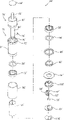
Fig. 2 be among Fig. 1 the rear perspective view of CMM;
Fig. 3 be among Fig. 1 the right side view (wherein main frame is removed) of CMM;
Fig. 3 A be among Fig. 1 the right side view of CMM, the protective sleeve that wherein covers on two long joints (longjoint) wherein slightly changes;
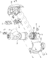
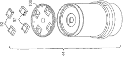
Fig. 4 is the partial, exploded perspective view of CMM of the present invention, has wherein expressed the pedestal and the first articulated jib part;
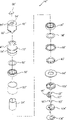
Fig. 5 is the partial, exploded perspective view of CMM of the present invention, has wherein expressed the second articulated jib part of pedestal, first articulated jib part and exploded;
Fig. 6 is the partial, exploded perspective view of CMM of the present invention, has wherein expressed the 3rd articulated jib part of pedestal, first articulated jib part and exploded;
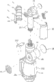
Fig. 7 is a partial, exploded perspective view, has wherein expressed a pair of scrambler of the present invention/bearing movement, and it is assembled between two two muff joints;
Fig. 8 be shown in Fig. 7 bearing/encoder cartridge and the front view of two muff joints;
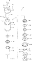
Fig. 9 is the decomposition diagram of short bearing/encoder cartridge of the present invention;
Fig. 9 A is the skeleton view similar to Fig. 9, and different is to have expressed single playback head;
Fig. 9 B is the decomposition diagram similar to Fig. 9, and different is to have expressed four playback heads;
Fig. 9 C is the skeleton view after the assembling similar to Fig. 9 B;
Fig. 9 D is the decomposition diagram similar to Fig. 9, and different is to have expressed three playback heads;
Fig. 9 E is the skeleton view after the assembling similar to Fig. 9 D;
Figure 10 is the cut-open view of movement shown in Fig. 9;
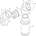
Figure 11 is the decomposition diagram of long bearing/encoder cartridge of the present invention;
Figure 11 A is the decomposition diagram similar to Figure 11, and different is to have expressed single playback head;
Figure 12 is the cut-open view of movement shown in Figure 11;
Figure 12 A is the movement cut-open view shown in Figure 12, has expressed two playback heads that can rotate together with the axis;
Figure 13 is the decomposition diagram of another bearing/encoder cartridge of the present invention;
Figure 13 A is the decomposition diagram similar to Figure 13, and different is to have expressed single playback head;
Figure 14 is the cut-open view of movement shown in Figure 13;
Figure 15 is the decomposition diagram of bearing/encoder cartridge of the present invention and balancing spring;
Figure 15 A is the decomposition diagram similar to Figure 15, and different is to have expressed single playback head;
Figure 16 is the cut-open view of movement shown in Figure 15 and equalizing feature;
Figure 17 is the vertical view that is used for two playback head assemblies of the bigger bearing/encoder cartridge of a kind of diameter of the present invention;
Shown in Figure 180 is the cut-open view of being done along the line 18-18 among Figure 17;
Shown in Figure 19 is the upward view of the two playback head assemblies shown in Figure 17;
Shown in Figure 20 is is used for the vertical view of two playback head assemblies of less bearing/encoder cartridge of the present invention;
Shown in Figure 21 is the cut-open view of being done along Figure 20 midship section 21-21;
Shown in Figure 22 is the upward view of the two playback head assemblies shown in Figure 20;
Figure 23 A is a block scheme of describing the electronics configuration that CMM adopted of the single playback head of use of the present invention;
Figure 23 B is a block scheme of describing the electronics configuration that CMM adopted of the two playback heads of use of the present invention;
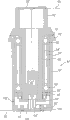
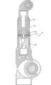
Shown in Figure 24 is CMM longitudinal sectional view of the present invention (wherein having removed pedestal);
Shown in Figure 24 A is the cut-open view of the CMM shown in Fig. 3 A;
Shown in Figure 25 is the amplification view of the part among Figure 24, has expressed the pedestal and the first long joint of the CMM among Figure 24;
Figure 25 A is the view of representing long joint according to another embodiment of the present invention and lacking the state that interconnects between the joint;
Shown in Figure 25 B is vertical positive view of the part among Figure 25 A;
Shown in Figure 26 is the amplification view of the part among Figure 24, has expressed the second and the 3rd long joint segments (long joint segment);
Shown in Figure 26 A and the B is the amplification view of the part among Figure 24 A, has expressed the second and the 3rd long joint and probe;
Shown in Figure 27 A is a decomposition side view, has expressed of the present invention first short joint/balanced component;
Figure 27 B is a skeleton view of expressing the element among Figure 27 A;
Figure 28 is the positive view of expression internal counter balance of the present invention;
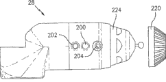
Figure 29 is the side direction positive view of first embodiment of measuring probe of the present invention;
Figure 29 A is the side view of another embodiment of probe of the present invention;
Figure 29 B is the cut-open view that the cross section 29B-29B along Figure 29 A is done;
Figure 29 C is used for a pair of " the carrying out (take) " of Figure 29 A-B or the skeleton view of " confirming (confirm) " switch;
Figure 30 A-C be successively the expression one contact probe assembly of the present invention and convert to rigid probe plan view;
Figure 31 is the side cross section view of another embodiment of measuring probe of the present invention;
Figure 32 is the decomposition diagram of one magnetic base of the present invention;
Figure 33 is the positive view of the magnetic base among Figure 32;
Figure 34 is the top plan view of the magnetic mount among Figure 32;
Figure 35 is the positive view of the CMM joint (joint) with two playback heads in the patent that comes from Raab ' 356;
Figure 36 is the positive view of the CMM joint (joint) with two playback heads in the patent that comes from Eaton ' 148;
Figure 37 is the side view with measuring probe of the 7th converter;
Figure 38 is and the similar side view of Figure 37 that different is comprising a detachable handle;
Figure 39 is the end view of the measuring probe among Figure 38; And
Figure 40 is the positive view of the measuring probe among Figure 38.
Embodiment
Referring to accompanying drawing 1-3, CMM of the present invention totally adopts mark 10 expressions, CMM10 comprise one have a plurality of that link together, can manually operated, articulated jib 14, an end of this articulated jib is connected on the base part 12, and the other end is connected on the measuring probe 28.Constituting by two types joint (joint) basically of articulated jib 14, promptly long joint (being used to do gyration) and short joint (being used to do pivotal motion).This long joint arranges that along the axial or longitudinal direction of this articulated jib short joint then preferably becomes 90 ° of layouts with respect to the longitudinal axis of this articulated jib basically.This long joint and the pairing of short joint occur, and the pairing structure in this joint is referred to as 2-2-2 (although also can adopt the structural form in other joint, for example 2-1-2,2-1-3,2-2-3 etc.) usually.Each that expressed these joint centerings among Fig. 4-6 is right.
Fig. 4 has expressed the right decomposition view in first joint, promptly long joint 16 and short joint 18.Fig. 4 has also expressed the decomposition view of pedestal 12, comprises portable power electronic installation 20, portable battery pack 22, magnetic mount 24 and two-piece type base housing 26A and 26B.All these elements all can be described in more detail below.
Importantly, it will be appreciated that the diameter of the various critical pieces of articulated jib 14 all is 28 to be tapered from pedestal 12 to probe.This tapered process is continuous, and perhaps shown in embodiment in the drawings, this being tapered is discontinuous or stair-stepping.In addition, each critical piece of articulated jib 14 can connect by the mode that is threaded, and therefore can eliminate the existing involved a large amount of securing member of CMM.For example, as what will set forth in the back, magnetic mount 23 is to adopt thread connecting mode to be installed on the first long joint 16.Preferably, this screw thread is a tapered thread, and it can carry out oneself's locking and can increase axial/bending stiffness.Perhaps, shown in Figure 25 A and 25B, as what will discuss in the back, the critical piece of this articulated jib can have complementary taper convex-concave end, and these ends have corresponding flange, and this flange can link together by bolt.
Referring to Fig. 5, second shown group leader joint and short joint are connected on described first group leader joint and the short joint.The second joint group comprises long joint 30 and short joint 32.With magnetic mount 24 is installed on the long joint 16 the same, long joint 30 also is connected on the screw thread of inside surface in long joint 16 by thread connecting mode.Equally, referring to Fig. 6, the 3rd joint set comprises the 3rd long joint 34 and the 3rd short joint 36.The 3rd long joint 34 is connected with thread connecting mode on the screw thread of inside surface in the second short joint 32.As to be described in detail below, probe 28 also is connected on the short joint 36 with thread connecting mode.
Preferably, each short joint 18,32 and 36 all is made of the aluminium matter element that casting and/or machining are crossed, and perhaps also can adopt light rigidity alloy or complex to constitute.Each long joint 16,30 and 34 preferred aluminium, light rigidity alloy or the fiber reinforced polymkeric substance of all being crossed by casting and/or machining constitute.Three pairs of right mechanical axis (promptly first pair comprises that the joint comprises that to 16,18, the second pairs the joint comprises that to 30,32, the three pairs the joint is to 34,36) in aforementioned joint align so that obtain level and smooth identical mechanical characteristic with respect to this pedestal.28 aforementioned tapered structure is preferred from pedestal 12 to probe, so that can be increased in the rigidity at the bigger pedestal place of load, the cross section at very important probe or handle place is less aspect can unobstructed use simultaneously.As will describing in detail in the back, on the two ends in each short joint bolster 38 is housed all, and all is covered with a protective cover 40 or 41 on each long joint.It will be appreciated that the first long joint 16 is subjected to the protection of base housing 26A, 26B, the protection that this base housing provided is identical for the protection type that the second and the 3rd long joint 30,34 is provided with protective cover 40,41.
According to an important characteristic of the present invention, a kind of molded (modular) bearing/encoder cartridge, for example short movement 42 shown in Fig. 7 and 8 and long cartridge 44 are all adopted in each joint of articulated jib.These movements 42,44 are installed in the opening of two muff joints 46,48.Each muff joint 46,48 all comprises the first cylindrical extension part 47 with first recess or sleeve 120 and has second recess or the second cylindrical extension part 49 of sleeve 51.Usually, sleeve 120 and 51 but also can adopt other relative angle structure each other at an angle of 90.Short movement 42 is arranged in each sleeves 51 of two muff joints 46 and 48 so that constitute a kind of articulation joint (hinge joint), simultaneously long cartridge 44 is arranged in the sleeve 120 of joint 46 (seeing Figure 25) and long cartridge 44 ' (seeing Figure 26) is arranged in the sleeve 120 of joint 48, thereby each all constitutes a kind of revolution longitudinally and connects (swivel joint).Molded bearing/encoder cartridge 42,44 allows that independent the manufacturing on it is equipped with the prestress of this molded encoder components or the duplex bearing movement of preload.This bearing encoder cartridge can be fixedly installed on the external bone parts (that is two muff joints 46,48) of articulated jib 14 subsequently.Adopt the remarkable advantage of this movement to be that it can high-quality produces these complicated subassemblies of articulated jib 14 at high speed.
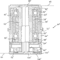
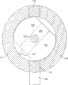
Among the described herein embodiment, four different cartridge types are arranged, that is, be used for two axial long cartridge in joint 30,34, the axial movement of pedestal that is used for joint 16, pedestal movement (it comprises an equalizing feature) and two the hinged movements that are used for joint 32 and 36 that are used for short joint 18 and 16.In addition, consistent with tapered articulated jib 14, the diameter of the movement (for example, being arranged in the movement in long joint 16 and short joint 18) of close pedestal is relative has than the joint 30,32,34 of minor diameter and 36 and Yan Yaoda is a little.Each movement all comprises a preload bearing arrangement and a converter, and in this embodiment, this converter comprises a digital encoder.Referring to Fig. 9 and 10, now the movement 44 that is arranged in axial long joint 16 is described.
Movement 44 comprises a pair of bearing 50,52 that is separated by interior cover for seat 54 and outer cover for seat 56.Importantly want preload on the bearing 50,52.In this embodiment, this preload provides by cover for seat 54,56, this cover for seat 54,56 has different length (interior cover for seat 54 is than about 0.0005 inch of outer cover for seat 56 weak points), thereby produces a previously selected preload when fastening on bearing 50,52.Bearing 50,52 adopts seal 58 to seal, and this assembly that these parts constitute is rotatably installed on the axle 60.Surface thereon, the end of axle 60 forms a upper body 62.Between axle 60 and axle upper body 62, form an annular space 63.Whole assembly is disposed in the core shell body 64, wherein adopts the combination of inner nut 66 and outer nut 68 firmly to be installed on the core shell body 64 with its bearing assembly by axle 60.It should be noted that the top 65 of shell body 64 will be accommodated in the annular space 63 in assembling.What be appreciated that is, carry out this bearing being applied force of compression when fastening at internal outer nut 66 and 68, thereby above-mentioned preload is applied on the bearing 50,52, and because therefore the length difference of internal and external partition cover (cover for seat) 54,56 can apply required preload.
Preferably, bearing 50,62 is two duplex ball bearings.In order to obtain enough preloads, it is very important making carrying plane parallel as much as possible.This depth of parallelism can have influence on the uniformity coefficient of the preload on the bearing periphery.Uneven load can cause very uneven moment of torsion sensation and can cause uncertain diameter run-out and reduce encoder performance.The diameter run-out meeting of the scrambler dish (will discuss below) that modularization is installed causes a kind of unfavorable fringe pattern shift below playback head.This situation can cause encoder angular measurement great error to occur.And the rigidity of this preferred duplex ball bearing structure is also directly related with separating of bearing.Bearing is at a distance of far away more, and this assembly has rigidity more.Adopt spacer sleeve 54,56 can strengthen the separation of this bearing.Because movement shell 64 is preferably aluminium matter, so spacer sleeve 54,56 preferably also adopts aluminium to make and accurately processing aspect the length and the depth of parallelism.Therefore, temperature change can not cause uneven expansion, and this uneven expansion can have influence on this preload.As previously mentioned, can obtain this preload by the difference that designs the length aspect of spacer sleeve 54,56 with a kind of known way.In case after this nut 66,68 was fastened fully, this length difference can cause a bearing preload.Use seal 58 that sealing bearing can be provided, rotatablely move and the precision and the arthresthesia (joint feel) of scrambler because any pollution of bearing all can have influence on all.
Although movement 44 preferably includes a pair of isolated bearing, movement 44 also can comprise single bearing or three or more bearings.Therefore, each movement needs a bearing at least, as subsistence level.
Connection movement of the present invention both can be done unlimited rotatablely moving, and perhaps also can do limited rotatablely moving as a kind of selection.In order to realize limited rotatablely moving, a groove 70 on the flange on the outside surface of housing 64 72 has formed a cylindrical rails 70 of holding a shuttle (shuttle) 74.This shuttle 74 will travel in track 70 till it is resisted against a dismountable shuttle retainer, and this shuttle retainer for example rotates stop set screw 76, can stop by this set screw to rotatablely move.The revolution that rotatablely moves can change as required.In a preferred embodiment, the revolution of shuttle can be defined as and be lower than 720 °.The type of rotation shuttle retainer herein has detailed description in the common U.S. Pat of transferring the possession of 5611147, all the elements of this patent comprise in this application in the mode of reference.
As mentioned above, in another alternative embodiment, unlimited rotatablely moving carried out in joint used in the present invention.Under a kind of in the back situation, adopted a kind of known slip ring assembly.Preferably, axle 60 has hollow or axial hole 78, and an end in this hole has a part 80 that diameter is bigger.On the shoulder that forms between axial hole 78 and 80 against a cylindrical slip ring assembly 82 is arranged.With respect to for this preload bearing assembly that proposes in this molded connection movement, (that is to say that it does not provide any mechanical function, only provide electricity and/or signal transfer function) that slip ring assembly 82 can not be that structure rents.Although slip ring assembly 82 can be the slip ring that can buy on any market, but in a preferred embodiment, slip ring assembly 82 comprises can be from United Kingdom Reading, the slip ring of the H series that the worker DMElectronics Ltd. company of BERKSHRE buys.This slip ring size is compact and have cylindrical structural, and can ideally be applicable in the hole 80 of axle in 60.The end that passes the axial hole 80 of axle 60 forms hole 84, and this hole 84 is communicated with conduit 86, and the size of this conduit 86 and structure can be held the electric wire that comes from slip ring assembly 82.This electric wire is by wire cover 88 fix in position and be protected, and this wire cover 88 is installed in conduit 86 and the hole 84.This electric wire is schematically shown by the mark among Figure 10 90.
As mentioned above, modular cartridge 44 comprises an above-mentioned preload bearing components and the following molded encoder structure that will describe.Still referring to Fig. 9 and 10, be used for this preferred converter of the present invention and comprise a moulded optical scrambler, this scrambler has critical piece in two, i.e. playback head 92 and grating dish 94.In this embodiment, a pair of playback head 92 is arranged in a playback head connector board 96.This connector board 96 is installed on the installing plate 100.Grating dish 94 preferred (preferably adopting a kind of suitable adhesive) is installed on axle 60 the lower support surface 102 and is spaced apart with this playback head 92 (this magnetic head is fixed by plate 100 supportings) and align with this playback head.One electric wire hoop 104 and gland bonnet 106 provide outermost covering for the lower end of housing 64.Electric wire 90 can be taken in and keep to electric wire hoop 104 as shown in Figure 10.What be appreciated that is, this scrambler dish 94 has and is fixed on being coated with bonding agent on 102 on the axle 60 and can be along with this rotation.Fig. 9 and 10 has expressed a kind of pair of playback head 92, and but, what be appreciated that is can use plural playback head, perhaps the single playback head of use as shown in Fig. 9 A.Fig. 9 B-C has expressed four playback heads 92 being installed in the plate 100 and has separated (also is suitable although adopt different relative spacings) with 90 ° compartment.Fig. 9 D-E has expressed three playback heads 92 being installed in the plate 100 and has separated (also is suitable although adopt different relative spacings) with 120 ° compartment.
For align disk 94 with one heart, providing a hole (not shown) that passes housing 64 in position near dish 94.Adopt a kind of instrument (not shown) will coil 94 subsequently and be pushed to concentric aligned position, making the bonding agent between dish 94 and the axle 60 solidify on this position so that will coil 94 locks in place.Subsequently in the described hole (not shown) that stopple 73 is inserted in the housing 64.
The position that importantly it may be noted that this dish 94 and playback head 92 can be conversely, is fixed on the outer cover for seat 56 and playback head 92 can be with axle 60 rotations thereby coil 94.Expressed such embodiment among Figure 12 A, wherein plate 96 ' (passing through bonding agent) is fixed on axle 60 ' upward so that therewith rotation.A pair of playback head 92 ' is fixed on plate 96 ' and upward and therefore rotates together with axle 60 '.Dish 94 ' is arranged on the supporting member 100 ', and this supporting member 100 ' is fixed on the shell 64 '.Under any circumstance, what be appreciated that is, no matter is that dish 94 or playback head 92 can be mounted to and rotate together with the axis.Importantly coil 94 and playback head 92 to be arranged in the movement (or joint) so that when keeping optical communication, can rotate relative to one another.Preferably, in the present invention the rotary encoder that is adopted than in U.S. Pat 5486923 and US5559600, disclose that is little, all the elements of these two patents all comprise in this application by the mode of reference.This modular encoder can buy from MicroE Systems company, and its trade name is Pure Precision Optics.These scramblers are interference between the basic detection of diffracted level with physical optics all, are close to perfect sinusoidal signal thereby generate from a photodetector array that inserts the interference fringe.Adopt the method for electronics this sinusoidal signal to be carried out interpolate value so that can detect the only displacement of sub-fraction optical stripe.
Adopt a kind of lasing light emitter, at first adopt lens to make this laser beam become parallel beam, sieve (sized) by an aperture subsequently.Collimated laser beam after this screening passes a grating, and this grating makes optical diffraction become to have the discrete stages (discrete order) of 0th and be subjected to all even levels (even order) that optical grating construction (gratingconstruction) suppresses.Because this 0 grade is suppressed, outside the 3rd branch stage (), there is a zone, in this zone, have only ± the mutual crossover formation one intimate pure sinusoidal interference of 1st level.In this zone, arrange one or more photodetector arrays (playback head), and when have relative motion between grating and the detecting device the almost pure sinusoidal output quantity of four channels of this photodetector array generation.Output quantity is carried out being inserted into desirable level of resolution (level of resolution) in electronics amplification, the normalization also.
Simplification to this coder structure has produced several advantages that are better than existing optical encoder.Only adopt a lasing light emitter and collimation optical device thereof, diffraction grating and a detector array just can measure.For comparatively clumsy existing conventional coders, this just makes encoder apparatus of the present invention seem very compact.In addition, direct relation between this grating and the fringe movement (fringe movement) weakened this scrambler to external world the caused error of environment susceptibility, and conventional device just is easy to be subjected to the influence of this error.And because this interference region is bigger, and can obtain almost sinusoidal interference in any position in this zone, therefore, the requirement of collimation tolerance (alignmenttolerance) is much loose more than existing scrambler requiring in this respect.
A significant advantage of aforementioned optical encoder is, and is much lower with respect to the strict degree of the precision of the deviation position of this scrambler dish and distance or distance and position to playback head.So just can obtain a kind of high-precision wheel measuring and a kind of packing that is easy to assemble.Adopt the encoder techniques of this " having tolerance (geometry tolerant) how much " to make that the cost of CMM10 significantly reduces and make that manufacturing is more easy.
People will recognize that although above preferred embodiment contains a kind of CD (optical disk) 94, the preferred embodiments of the present invention also can comprise any optical interference candy strip, and this pattern makes this playback head can detect relative motion.As used in this, this interference fringe pattern has been expressed any periodic array of the optical element that is used for measuring motion.These optical elements or interference fringe pattern can be installed on aforesaid rotation or the fixing dish, perhaps can store, fixing or arrange or be placed on the parts (for example axle, bearing or housing) of any relative motion of this movement.
In fact, this playback head and relevant periodic array or pattern must not need fully based on (aforesaid) optical device.Broadly, this playback head can also be read many other periodic patterns of (or detecting) many other measurable quantity or characteristic, and these measurable quantity or characteristic can be used for detecting motion, for example is generally to rotatablely move.These other measurable characteristic for example can comprise reflectivity, opacity, magnetic field, electric capacity, induction coefficient or surfaceness (noticing that the surfaceness pattern can adopt to have camera for example the playback head or the sensor of this form of CCD camera are read).In these cases, playback head will be measured for example cycle variation of magnetic field, reflectivity, electric capacity, induction coefficient, surfaceness etc.As term used herein, a kind of optics playback head as a preferred embodiment of term " playback head " any employing of expression is analyzed sensor or the converter and the relevant electronics device of measurable quantity or characteristic.Certainly, the periodic pattern of being read by playback head can be positioned on any surface, as long as have relative motion (be generally and rotatablely move) between playback head and the periodic pattern.Some examples of periodic pattern comprise with pattern form be deposited on one the rotation or fixed part on magnetic, the induction or capacitive media.And, if surfaceness is this periodic pattern to be read, just there is no need deposition or a periodic pattern independently is provided, because use this surfaceness on the parts that any playback head relevant with this (may be a camera, for example be the CCD camera) be connected just passable.
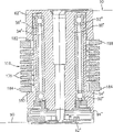
As mentioned above, Fig. 9 and 10 expressions is to be used for the molded bearing of axial long joint 16 and some examples of encoder cartridge.Shown in Figure 11 and 12 is bearing and the encoder cartridge that is used for axial long joint 30 and 34.These cartridge assemblies basically all to Fig. 9 with similar shown in 10 and therefore be labeled as 44 '.Can draw some trickle differences that are different from movement 44 significantly from these figure, these differences for example relate to wire cover/cover 88 ' structure different, electric wire hoop/cover 104 ', 106 ' the position difference slightly of the flange 72 ' of the upper end of difference and shell body 64 ' slightly.And the flange between housing 64 ' and the axle upper body 62 is flared.Certainly, the relative length of Figure 11 and the various parts shown in 12 is also different with the situation shown in Fig. 9 and 10.Because all these parts are all similar basically, so these parts all adopt identical numeral to add a symbol, and " ' " refers to.Figure 11 A is similar to Figure 11, and different is, and that to express is the embodiment with single playback head.
Referring to Figure 13 and 14, the bearing in the short articulation joint (short hinge joint) 32 and 36 that shown is and the view sub-anatomy of encoder cartridge.Shown in the axial long joint 44 ' in Figure 11 and 12, the movement that is used for short articulation joint 32 and 36 is similar with the movement of describing in detail above 44 basically, therefore the component labelling of these movements is 44 ", and similar element adopts original bamboo to add symbol " " " represent.It will be understood that, because movement 44 " will be used for short joint 32,36, therefore not need slip ring assembly, because this electric wire will pass this axial hole 78 ", 80 " simply owing to the pivotal motion in these joints.Figure 13 A and Figure 13 are similar, expression that different is be the embodiment of a single playback head.
At last, referring to Figure 15 and 16, the molded bearing/encoder cartridge of short articulation joint 18 is illustrated as 108.Cognosciblely be, basically all parts of movement 108 all with movement 44,44 ' and 44 " in parts similar or identical, wherein important difference is to include a balanced component.This balanced component comprises a balancing spring 110, and this spring housing is contained in housing 64 " goes up and is that CMM10 provides a kind of important equilibrium function in the mode that will be described with reference to Figure 26-28 below a kind of.Figure 15 A is similar to Figure 15, but shown in be a single playback head embodiment.
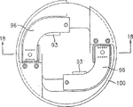
As implied above, in a preferred embodiment, in this scrambler, can adopt more than one playback head.What be appreciated that is, can be by because the measurement of angle of scrambler is carried out in the diameter run-out or the radial motion of the dish that the load that is applied causes.It has been determined that two playback heads each other in 180 ° of layouts can cause diameter run-out, this diameter run-out is returned in each playback head and is produced cancellation effect.These cancellation effects are averaged obtain final " (immune) of a release " angle measurement.Therefore the possibility that adopts two playback heads and resultant error counteracting can cause makeing mistakes reduces and obtains more accurate encoder measurement.What Figure 17-19 represented respectively is upward view, cut-open view and the vertical view that is used for two playback head embodiment of larger-diameter movement, and this large diameter movement for example can find in joint 16 and 18 (just those joints of the most close pedestal).Therefore, a pair of circuit board 96 is installed on the cartridge end cap 100, all has one on each circuit board 96 and adopt mechanical system playback head 92 mounted thereto.This playback head 92 is preferably arranged for and is spaced apart from each other 180 °, in order to the error counteracting that diameter run-out or radial motion caused by described dish.Each circuit board 96 comprises also that all one is used for this circuit board 96 is connected to following internal bus that will describe and/or the connector 93 on other electric wires.Parts shown in Figure 20-22 are identical with the parts shown in Figure 17-19 basically, and wherein main difference is that a cartridge end cap 100 than minor diameter is arranged.Be connected with the described of joint 30,32,34 and 36 on these two playback head embodiment than the minor diameter movement than minor diameter.
Preferably, adopt at least two playback heads (or multihead more, four playback heads shown in three playback heads shown in Fig. 9 D-E and Fig. 9 B-C for example) also can be adopted, thereby reduce the manufacturing cost and the complicacy of this measuring machine significantly by multiple common coordinate measuring machine.For example, U.S. Pat 5794356 (is designated hereinafter simply as patent ' 356, and comprise in this application in the reference mode) described in a kind of coordinate measuring machine in the structure in each joint all simple relatively, each joint all comprises first housing and second housing, this first housing is maintained fixed and has a joint half sheet (joint half), and second housing is maintained fixed and have second joint half sheet, and this first and second housing has the preload bearing, and this bearing can rotate it relatively.First housing is fixed a scrambler that installs and second problem comprises an axial arranged interior axle, in this axle extend in first housing and with the scrambler that installs from this this scrambler axle of protruding be complementary.This existing scrambler that installs requires not have load to apply thereon, although and should in the axis of axle and the axis of this scrambler that installs right be not too neat, the motion of second housing will accurately be delivered on this scrambler so that keep the wheel measuring of degree of precision.In order to adapt to, connect a special hitch bar between the axle in just need and being somebody's turn to do at this scrambler axle in the manufacturing tolerance aspect axially not lining up.This member is as in the patent of Raab ' shown in Figure 7 in 356.
Contrast, shown in Figure 35 is a kind of variation structure, ' coupling device of CMM is removed and adopts scrambler dish 96 and end cap 100 to substitute with the scrambler that installs to the patent of Raab in 356.At this, two joints are 90 ° of layouts each other, and each joint has first housing 420 and second housing 410.In axle 412 extend to first housing 410 from second housing 420.As shown in the figure, scrambler dish 96 for example adopts bonding agent to be installed in this end of interior 412, and end cap 100 is fixed in first housing 420.But, be understandable that, scrambler dish 96 can be fixed in first housing 420 and end cap 100 can be fixed on the axle 412 and can not have influence on the running in this joint.
As mentioned above, the possibility that adopts two (or more) playback heads and resultant error counteracting can cause makeing mistakes reduces and obtains more accurate encoder measurement, although axis is not too neat to getting.In addition, the direct relation between grating and the fringe movement has weakened this scrambler susceptibility of the error that causes of environment to external world, and existing apparatus then is easy to be subjected to the influence of this error.And because this interference region is bigger, and each position in this zone can obtain almost sinusoidal interference, therefore to the requirement of alignment tolerances than aforementioned existing scrambler require much loose.
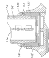
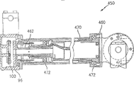
In another example, the U.S. Pat 5829148 of Eaton (' 148 that are designated hereinafter simply as the patent of Eaton, its mode with reference covers among the application) a kind of existing CMM described, wherein a scrambler that installs is by providing main rotating shaft to hold to form the integral part in each joint, do not need therefore that ' situation that axially do not line up in 356 compensates to aforesaid Raab patent.But, because this scrambler provides main rotating shaft to hold, therefore importantly this scrambler structurally has shock resistance (rugged) and can stand various loads and can not have influence on its performance.This has just increased the cost and the clumsy degree of this scrambler.Shown in Figure 4 in the patent of this structure such as Eaton ' 148.
Contrast, shown in Figure 36 is a kind of variation structure, wherein, this scrambler that installs in the patent of Eaton ' 148 and the coupling shaft in one of them joint are removed and are substituted by end cap 100 and scrambler dish 96.At this, first housing 470 keeps end cap 100 and keeps the interior axle 462 of second housing 460 by bearing 472.Interior axle 462 extends to terminal near end cap 100, and scrambler dish 96 for example adopts bonding agent to be installed in this end of interior 462.Embodiment as shown in Figure 35 is the same, and adopting two (or more) playback heads to return the cost and the complicacy that reduce this joint significantly simultaneously can loss of accuracy.
Look back at Figure 23 A, shown in it is the block scheme of electronic circuit that is used for single playback head embodiment of Fig. 9 A, 11A, 13A and 15A.What be appreciated that is, CMM10 preferably includes an external bus (being preferably usb bus) 260 and an internal bus (being preferably RS-485) 261, this external bus is designed to extendible, for use in a plurality of scramblers and a handrail (rail) of installing from the outside or additional turning axle, for example the 7th.This internal bus is preferably consistent with RS485, and this bus preferably is arranged to and can be used as a serial network in the identical mode of the serial networks a kind of and data that are used for transmitting the converter that comes from a portable CMM articulated jib, and this CMM articulated jib is disclosed in the common U.S. Pat of transferring the possession of 6219928 (its full content comprises in this application in the reference mode).
Referring to Figure 23 A, be understandable that each scrambler in each movement all links to each other with an encoder plate.The encoder plate of the movement in the joint 16 is disposed in the pedestal 12 and in Figure 25 and is marked as 112.Joint 18 and 30 scrambler are handled on a pair of encoder plate, and this dual coding device plate is arranged in the second long joint 30 and is marked as 114 at Figure 26.Figure 26 has also represented a kind of similar dual coding device plate 116, is used for the scrambler of joint 32 and 34, and encoder plate 116 is arranged in the 3rd long joint 34 as shown in figure 26.At last, this end encoder plate 118 is arranged in measurement probe handle 28 as shown in figure 24 and is used to handle the scrambler in short joint 36.In these encoder plates 114,116 and 118 each all is connected with a thermopair so that provide because the thermal compensation that temperature transient causes.Each encoder plate 112,114,116 and 118 all includes embedded analog to digital conversion, encoder to count and serial port communications (serial port communication).Each encoder plate all has the short-access storage of read programmable so that service data can be stored in this locality.Primary processor plugboard 112 also is can be by the zone (field) of external USB bus 260 programmings.As mentioned above, this internal bus (RS-485) 261 be designed to expandable type for use in more scrambler, this scrambler also comprises a handrail (rail) and/or the 7th turning axle of installing from the outside.Be provided with an axis hole so that provide diagnosis for internal bus.Because the capacity of external USB communication protocol can be connected to a single application scenario (single applicaiton) with the CMM that is expressed as 10 in a plurality of these accompanying drawings.And can be owing to identical former thereby a plurality of application are connected on the single CMM10.
Preferably, each encoder plate 112,114,116 and 118 all comprises one 16 digital signal processor, for example can be from the processor that is designated DSP56F807 of Motorola purchase.This single processing element combines multiple processing feature (these features comprise serial communication, integration decoding, A/D converter and at board memory), therefore can reduce the sum of the required chip of each encoder plate.
According to another key character of the present invention, each scrambler all links to each other with a chip 120 with personalized identification.This chip is used for identifying each individual encoder and therefore identifies each other bearing/encoder modular cartridge, thereby can carry out quality control, test and reparation easily and quickly.
Figure 23 B is an electronics block diagram similar to Figure 23 A, but shown in be Figure 10,12,14 and 16-22 in two playback head embodiment.
Assembly below with reference to Figure 24-26 pair of each movement in this articulated jib 14 is described (notices that articulated jib 14 shown in Figure 24 does not have pedestal 12.Also have, Figure 24-26 has adopted the single playback head embodiment shown in Fig. 9 A, 11A, 13A and the 15A).As shown in figure 25, the first long joint 16 comprises a relatively long movement 44, and the upper end of this movement is inserted in the cylindrical sleeve 120 of two muff joints 46.Movement 44 is securely fixed in the sleeve 120 by suitable adhesive.The relative lower end of this movement 44 is inserted in the extension (extension tube), and in this embodiment, extension can be aluminium matter sleeve pipe 122 (but sleeve pipe 122 also can comprise a kind of rigidity alloy or compound substance).Movement 44 adopts suitable adhesive to be fixed in this sleeve pipe 122 once more.The lower end of this sleeve pipe 122 comprises a bigger overall diameter part 124, has internal thread 126 on this part.This screw thread is outwards tapered and be arranged to and can carry out threaded engagement with the inside tapered screw thread 128 (know and be illustrated in Fig. 4) that is arranged on the magnetic mount housing 130.As mentioned above, all joints of CMM10 all adopt this tapered thread to interconnect.Preferably, this tapered thread is can fastening American standard taper pipe thread (NPT) the type screw thread of oneself, does not therefore need lock nut or other fastener.This screw thread is also allowed and should be comprised thread lock agent (thread locking agent).
Referring to Figure 26, the same with the first long joint 16, long cartridge 44 ' is that the employing adhesive is in the cylinder open 120 ' of two muff joints 46 '.The shell body 64 ' of this movement 44 ' comprises a shoulder 132 that is formed by the lower surface of flange 72 '.These shoulder 132 supporting cylinder-shaped extension pipes 134, this extension setting also is enclosed within on the outside surface of shell body 64 '.Extension is used for these joints so that form an adjustable length pipe that is installed on the threaded parts.Therefore extension 134 stretches out from the bottom of shell body 64 ' and has wherein inserted a threaded sleeve 136.Adopting suitable adhesive that this shell body 64 ' is bonded on the extension 134 and with sleeve pipe 136 and extension 132 bonds together.The end of sleeve pipe 136 is a tapering part, has external thread 138 on this tapering part.This external thread matches with internal thread 140 on being positioned at web member 142 with thread connecting mode, and this web member has adopted bonding way to be fixed in the opening 144 of two muff joints 48 before this.Preferably, extension 134 adopts compound substances to constitute, and for example a kind of suitable carbon fibre composite, and threaded sleeve 136 is made of aluminium is so that be complementary with the thermal characteristic of this pair socket joint 48.What be appreciated that is, PC spot 114 is fastened on the supporting member 146, and this supporting member is fixed on again on two socket joint parts 142.
Except above-mentioned being threaded, one or more or all joints can adopt the threaded fastener as shown in Figure 25 A-B to interconnect.Be not the threaded sleeve 136 among Figure 26 but sleeve pipe 136 ' among Figure 25 B has smooth tapered end 137, this tapered end is contained in one to have in the supporting member 142 ' of complementary conical sleeve.Flange 139 136 ' stretches out along periphery from sleeve, has a collection of bolt hole (being 6 bolts hole in this example) on this flange, passes these bolts hole bolt 141 is installed.Bolt 141 is installed in the corresponding bolts hole with thread connecting mode along the upper surface of socket support 142 '.Extension 134 ' is sleeved on the sleeve pipe 136 ' among the embodiment shown in Figure 26.The taper convex-concave interconnection of these this complementations in joint has improved linkage interface with respect to prior art.
Still referring to Figure 26, the long cartridge 44 in the 3rd long joint 34 " adopts the mode similar with the movement 44 ' in long joint 30 to be fixed on the articulated jib 14.That is to say an opening 120 of movement 44 " top adopt bonding mode to be fixed to two socket joint 46 " " in.Extension 148 (preferred adopt described compound substance constitutes when describing at pipe 134) is sleeved on shell body 64 " to be gone up and by stretching out on it; cooperate sleeve pipe 150 so that hold one, this cooperation sleeve pipe is fixed on the internal diameter of extension 148 with bonding mode.Cooperate the end of sleeve pipe 150 to form a tapering part, have external thread 152 on this tapering part and match, be bonded in before this supporting member 154 on the cylindrical sleeve 156 in two socket joint 148 ' with complementary internal thread 153 on two socket joint parts 154.The printed circuit board (PCB) 116 same PCB supporting members 146 ' that adopt are connected on this pair socket joint, and this PCB supporting member 146 ' is fixed on two socket joint parts 154.
As described at Fig. 7 and 8, short joint movement 44 ' in Figure 13 and 14 and the movement 108 among Figure 15 are arranged between two two socket joint 46,48 simply and adopt a kind of suitable bonding to be fixed in this pair socket joint.Therefore, this length movement can both more easily couple together each other in right angle (any angle outside can meeting at right angles if necessary).
Aforesaid molded bearing encoder cartridge has constituted as the patent at aforementioned Raab a kind of important techniques progress of the portable CMM as shown in patent ' 148 of ' 356 and Eaton.This be because, this movement (or shell of this movement) has in fact formed the structural detail in each joint, this articulated jib has been formed in each joint.In the meaning of this employed term " structural detail " is that the surface (for example movement housing) of this movement is rigidly connected on other structural elements parts of articulated jib, so as under the situation that does not make this articulated jib distortion (or can only be out of shape minimum at most) transferring rotational motion.This and conventional portable CMM (for example disclosed in patent ' 148 of patent ' 356 of Raab and Eaton the sort of) form contrast, wherein, need independent and distinct joint component and transmitting element, because this rotary encoder is the part (but being the part of transmitting element) of joint component.In fact, the present invention does not need independent transmitting element (for example transferring elements), because the function of joint component and transmitting element enough has been integrated in the single moulding part (that is movement).Therefore, different with the articulated jib that constitutes by independent and distinct joint and transmitting element, the articulated jib that the present invention has adopted a kind of assembly by the length joint component (that is, movement) to constitute, these length joints all are the structural details of this articulated jib.This can obtain better efficient relative to existing technologies.For example, in patent in ' 148 and patent ' 582 in one joint/transferring elements assembly the quantity of employed bearing be four (two bearings are arranged in the joint and two bearings are arranged in the transferring elements), and the molded bearing/converter movement among the present invention that runs quickly can use a minimum bearing (although using two bearings for preferred) and still can realize identical functions (although can adopt a kind of difference and improved mode).
Figure 24 A and 26A-B are some cut-open views similar to Figure 24-26, but express be Figure 10,12,14 and 16-22 shown in two playback head embodiment, and be the cut-open view of the CMM10 ' shown in Fig. 3 A.
The total length of this articulated jib 14 and/or each arm section can change according to its occasion that will use.In one embodiment, the total length of this articulated jib is approximately 24 inches and the measured value of about 0.0002 to 0.0005 inch order of magnitude is provided.The size of this articulated jib and measuring accuracy provide a kind of can the adaptation preferably to adopt typical hand-operated tools for example milscale, altitude gauge, slide calliper rule etc. just can be realized the portable CMM that measures immediately.Certainly, articulated jib 14 can have less or bigger size and accuracy class.For example, the total length of bigger articulated jib is 8 feet or 12 feet, and measuring accuracy is 0.001 inch accordingly, therefore can be used in the most real-time inspection purposes or is used for reverse-engineering.
CMM10 can also use with controller mounted thereto, and this controller is used to carry out one as the executable program in the relative simplification disclosed in aforementioned patent US5978748 and the U.S. Patent application NO.09/775226; Perhaps CMM10 can use with the program or the main frame 172 of a relative complex.
Referring to Fig. 1-6 and 24-26; in a preferred embodiment; in long joint and the short joint each all is subjected to the protection of an elastomeric bumpers or cover, and this impact damper or cover role are restrictions than high impact power and a kind of comfortable grip position with ergonomics (and a kind of outward appearance of feeling comfortable of making us from attractive in appearance going up) is provided.Long joint 16,30 and 34 all is subjected to the protection of removable rigid plastic (for example ABS) cover, and this rigid plastic cover plays the effect of the protective device of a kind of protecting against shock and wearing and tearing.For the first long joint 16, this removable rigid plastic cover can form two-piece type base housing 26A and 26B, as shown in Figure 4.Long joint 30 and 34 each all be subjected to a pair of case spare 40 and 41 (as illustrated in Figures 5 and 6) protection, this group case spare can adopt suitable screw to tighten together with the clam shell form so that form a protective sleeve.Be understandable that in a preferred embodiment, this removable rigid plastic cover that is used for each long joint 30 and 34 all surrounds the extension 134 and 138 that this is preferably compound substance (carbon fiber) respectively.
Preferably, one of them cover for example covers part 41, comprises the support column 166 built in wherein inclination of phantom one by one, and this support column limits the rotation at the ancon place of this articulated jib, thereby prevents that under static state probe 28 collides pedestal 12.It is the clearest that this shows in Fig. 3,24 and 26.What be appreciated that is that therefore this support column 166 can limit unnecessary impact and wearing and tearing.
As will at Figure 29 and 31 described, probe 28 can also comprise a removable plastic safety cover, this protective cover adopts a kind of hard plastics to make.
Shown in Fig. 3 A, 24A and the 26A-B is interchangeable protective sleeve 40 ', 41 ', and these protective sleeves also have the clamshell style structure, and different is that they adopt clamping plate (strap) or spring clamp 167 rather than threaded fastener to fix in place.
Each short joint 18,32 and 36 all comprises a pair of elastic body (for example thermoplastic elastomer, for example SANTOPRENE ﹠amp; COMMAT) impact damper 38, with foregoing and clear expression in Fig. 1-3 and 5-6 the same.Impact damper 38 can adopt a kind of threaded fastener, suitable adhesive or adopt any other suitable mode to install.Elastic body or rubber bumper 38 will limit higher impulsive force and provide has the comfortable holding area that aesthetic feeling is pleasant and have ergonomics.
Aforementioned protective cover 40,41,40 ', 41 ' and impact damper 38 can be changed ( base housing 26A, 26B are too) easily and make articulated jib 14 to rebuild fast and at an easy rate under the situation of the mechanical property that does not influence CMM10.
Still referring to Fig. 1-3, base housing 26A, 26B comprise at least two cylindrical propeller boss (boss), are used for installing as a spheroid shown in 168 among Fig. 3.This spheroid can be used for installing the clamp computer mount 170 of clamp type, and the main officer of Tibet clamper is supporting portable or other computer installations 172 (for example described " main frame ") again.Preferably, cylindrical propeller boss is arranged on any side of this base housing 26A, B, makes this spheroid and clamp computer mount can be installed in any side of this CMM.
Referring now to Figure 15,16,27A, B and 28, this preferred equalizing feature that is used for CMM10 is described.Usually, portable CMM described herein has adopted a kind of volute spring of installing from the outside, and this volute spring is installed in the outside of articulated jib so that as an equalizing feature independently with a kind of form of pole bracket.Contrast, the present invention adopts a kind of internal counter balance that constitutes one fully, and this equalizing feature makes the whole exterior contour of this articulated jib reduce.Usually, existing equalizing feature all is to adopt a kind of coiling volute spring in balanced controls.But according to an important feature of the present invention, what this equalizing feature adopted but is a kind of volute spring that adopts machining to come out (relative with the coiling volute spring).Shown in Figure 16 and the 27A-B is the spring 110 that this employing machining is come out, and this spring 110 adopts single metal (steel) cylinders to form, and this metal cylinder forms the ring 174,176 of a pair of terminal relative broad relatively at this spiral by machining and some constitute the ring of the relative narrower of the middle spring coil between the invalid spring coil 174,176.What be appreciated that is, the invalid spring coil 174,176 of this broad respectively with the side surface 180 and the housing 64 of axle 62 ' " side surface 182 be meshed, prevent spring 110 transverse movements thus.The firm invalid spring coil 174,176 of broad plays the effect of an anti-twist device and the function that is better than existing wind spring is provided.Invalid spring coil 174 preferably includes pair of locking post 184,186 (although can only with a locking column) and invalid spring coil 176 comprises a locking column (locking post) 188.
Referring to Figure 27 B, each two socket joint 46,48 all comprises as the groove shown in mark 190 and 191, is used to hold corresponding locking column 184,186 or 188.Referring to Figure 28, although locking column 184,186 can remain in the suitable groove of two socket joint 48 with stationary state, the position of locking column 188 be can change in case make on the spring 110 whole wind-up optimization and the most effective equilibrant is provided.This can adopt a kind of threaded hole 192 to realize, screw 194 is installed in this threaded hole.As shown in figure 28, can operate it is contacted with locking column 188 and counterclockwise promote this locking column 188 along inner guide groove 196 in a circumferential direction to screw 194, shown in Figure 27 B, this inside guide groove and locking column to enter groove 190 vertical.Preferably in factory, just screw 194 is arranged in and makes spring 110 optimized positions.
What be appreciated that is, in the process of using this articulated jib 14, this scrambler/bearing movement 108 will play the effect of an articulation joint, and in case when being inserted into and adopting bonding way to be fixed in the sleeve of two socket joint 46,48, this locking column 184,186 and 188 will be locked in its corresponding grooves.When the relative socket joint 46 of socket joint 48 (through the articulation joint of movement 108) was rotated, this spring 110 will rolling-in.When its original position was got back in needs socket joint 48 rotation, the take-up force of this spring 110 will loosen and required equilibrant is provided.
When needs are put upside down installation articulated jib 14, for example be installed in thing 4 on grinding machine, crossbeam or the ceiling, the orientation of spring 110 can be turned (or conversely) around equally so that can obtain the necessary required proper orientation of balance.
One preferred embodiment of measuring probe 28 is described referring to Figure 29 and 30A-C.Probe 28 comprises a housing 196, and inner space 198 is arranged in this housing, is used to hold printed circuit board (PCB) 118.What be appreciated that is, housing 196 constitutes two socket joint of the above-mentioned types and comprises sleeve 197, bonds to a support unit 199 in this sleeve, and this support unit is used to support circuit board 118.Preferably, handle 28 comprises two switches, promptly carries out (take) switch 200 and confirms (confirm) switch 202.These switches by the operator be used in operating process (by carrying out switch 200) measure also (by confirming switch 202) and confirm this measurement.According to an important feature of the present invention, but this switch is come so that in use make the energy minimization of obscuring by difference each other.This difference can adopt multiple mode to carry out, these modes comprise for example to make switch 200,202 have different height and/or has different lines and (it should be noted that, impression again on the switch 202, and the upper surface of switch 200 is level and smooth in contrast) and/or have a different color (for example switch 200 for green switch 202 for red).Still according to a key character of the present invention, pilot lamp 204 also links to each other so that indicate suitable detection behavior with switch 200,202.Preferably, pilot lamp 204 is a kind of bicolored light so that for example pilot lamp 204 is when measuring (and when pressing green executive button 200) show green and when confirming to measure (and when pressing red ACK button 202) show red.Utilize a kind of existing LED just can realize using polychromatic light at an easy rate.In order to help to grip,, on the part of probe 28, provide the outer protective cover that is labeled as 206 the above-mentioned type in order to produce improved aesthetic feeling and for shock-resistant.Switching circuit board 208 is used for button 200,202 and pilot lamp 204, and this circuit board is by support unit 199 supportings.Switching circuit board 208 is electrically connected with circuit board 118, and the element that is used for handling this switch and pilot lamp and the short articulation joint 36 of processing is installed on this circuit board 118.
According to another key character of the present invention and referring to Figure 29 and Figure 30 A-C, probe 28 comprises a permanent contact trigger probe and a dismountable lid of installing, and this lid matches to merge with a stationary probe and protects this to contact trigger probe.Shown in the mark 210 among Figure 29 is this contact trigger probe mechanism, and this probe mechanism is a pedestal with a kind of three kinematics of point probe bases of simplification.The common structure of compromising comprises a probe nose 212, and this preceding nose contacts with the spheroid 214 that is subjected to contact spring 216 bias voltages.Three contact plugs 212 (having only one at 218 places shows) all with a circuit contacts of hiding.All can cause in three contact plugs 218 any one to rise to any power that the probe nose applies, and the rising of this contact plug can cause this circuit of hiding to be opened extorting a confession so drive a switch.Preferably, contact trigger probe 210 can also be with 200 collaborative works of foregoing " execution " switch.
Shown in Figure 30 B, when using contact trigger probe 210, protectiveness threaded cover 220 can be installed on trigger probe 210 screw thread 222 on every side threadably.But, when needs adopt a kind of stationary probe rather than adopt the contact trigger probe, can remove this detachable lid 220, as Figure 29 the sort of required stationary probe shown in the mark 224 among the 30A-C be installed on the screw thread 222 with thread connecting mode.What be appreciated that is, although stationary probe 224 has a ball mounted thereto, any heteroid required stationary probe is installed on the probe 28 by screw thread with thread connecting mode easily.Trigger probe assembly 210 is installed in the housing 228, and this housing 228 can be installed in the threaded connector 230 with being threaded, and this threaded connector forms the part of probe housing 196.This being threaded mutually makes that contacting very much trigger probe 210 is completely integrated in this probe 28.A kind of proposition of fully-integrated probe has showed key character of the present invention and significantly has been different from the existing detachable contact probe that is installed on the existing CMM.In addition, this permanent contact trigger probe of installing also and easily converts aforesaid hard probe to.
What Figure 29 A-C disclosed also is another preferred embodiment of measuring probe of the present invention.In Figure 29 A-C, the measuring probe shown in 28 ' is substantially similar to the measuring probe 28 shown in Figure 29, and its key distinction is the textural of " execution " and " affirmation " switch.Different with the distributing button-type switch shown in Figure 29, measuring probe 28 ' has adopted two couples of arc oblong switches 200a-b and 202a-b.The every couple of corresponding oblong switches 200a-b and 202a-b are correspondingly corresponding to the execution switch described in Figure 29 with confirm switch.This embodiment of this measuring probe 28 ' is that with respect to the advantage of measuring probe 28 this embodiments every pair of oblong switches 202 and 200 in fact all surrounds the whole circumference of this measuring probe (perhaps surrounding the most of at least of circumference) and therefore easier operator's driving by this portable CMM.The same with the embodiment shown in Figure 29, pilot lamp 204 links to each other with each switch, and this pilot lamp 204 and switch 200,202 are installed on the corresponding circuit board 208 '.Still the same with the embodiment shown in Figure 29, switch 200,202 can adopt for example different height, different lines and/or different colors to distinguish.Preferably, switch 200,202 floats slightly so that this button can be activated when being pressed by any position along this button.The same with the embodiment shown in Figure 29, used the outer protective cover of the above-mentioned type at 206 places, and this protective cover is installed on a part of probe 28 '.
Referring to Figure 31, a kind of alternative measuring probe that is used for CMM10 is shown in mark 232.Measuring probe 232 is similar to the measuring probe 28 among Figure 29, and the key distinction wherein is that probe 232 comprises a rotary handle cover 234.This rotary handle cover 234 is installed on a pair of isolated bearing 236,238, and this bearing is installed in again on an inner core or the supporting member 240, thereby this rotary cover 234 can be freely around inner core 240 rotations.
Bearing 236,238 is preferably transverse bearing and makes because the additional moment on this articulated jib that probe handle produces minimizes.It should be noted that this switching circuit board 208 ' and corresponding switch 200 ', 202 ' and LED204 ' all be installed on this rotary handle cover 234 so that therewith rotation.During rotation, adopt a kind of common slip ring mechanism 242 to provide electrical connection for treatment circuit plate 118 ', this slip ring mechanism comprises some existing isolated spring fingers (spring finger) 242, and this spring detent contacts with stationary annular groove 244.These contact grooves 244 adopt slip ring conductor 242 to be electrically connected with circuit board 118 ' again.Therefore this rotary handle cover 234 and switch module adopt slip ring conductor 242 to be electrically connected with inner core or probe shaft 240.The rotation of this probe handle cover 234 makes switch 200 ', 202 ' to be oriented and is convenient to the user.This makes that this articulated jib 14 ' can be by making the bright power of impunity real example (undocumented force) minimize accurately and measure in operating process.Some suitable recesses 246 and 248 are made and be which is provided with to this rotary handle cover preferably by a rigid polymer, so that make things convenient for the operator of this probe to grip easily and control.
Be understandable that the remainder of probe 232 and probe 28 are quite similar, be included in permanent and a contact probe 210 that one is installed is set in the lid 220.It is pointed out that switch 200 ', 202 ' all has different height and surface pattern so that conveniently recognized.
In the CMM field, a significant advantage of rotary handle cover 234 is that he can weaken and resembles needs to the 7th turning axle disclosed in the aforesaid U.S. Patent US5611147.What be appreciated that is, increases the 7th meeting and makes that CMM is more complicated and expensive and increased the possibility that system causes error.Use rotatable probe 232 to weaken, because it makes probe can be provided at the required rotation of handle position of probe end under the complex situations that do not have the 7th converter and corresponding bearing, scrambler and electron device to the needs of a kind of " real " the 7th.
Use at needs under the situation of the measuring probe with " really " the 7th, that is to say to have at measuring probe under the situation that is used to measure the 7th rotary encoder that rotatablely moves, Figure 37-40 has expressed this middle measuring probe.Referring to these figure, shown measuring probe 500 has such measuring probe, this probe is similar to the measuring probe among Figure 29 basically, its key distinction has been to insert the molded bearing/converter movement 502 of type as mentioned above, carries out and confirms that switch 540,506 is positioned at the side of this measuring probe and comprises a detachable handle 508.
What be appreciated that is, this molded bearing/converter movement 502 is similar to the movement of describing in detail above basically and comprise: a rotatable axle, the a pair of bearing that is positioned on this, one optical encoder dish, that at least one (being preferably two) optics playback head is spaced apart from each other and with this scrambler dish optical communication and a housing that surrounds this bearing, optical encoder dish, playback head and at least a portion axle so that constitute the molded bearing/converter movement of this dispersion (discrete).The circuit board 503 of scrambler electron device is arranged in the opening 504 of probe 500.Paired execution and ACK button 504,506 are arranged in any side of housing parts 510 of the downward protrusion of probe 500, and wherein these buttons are connected with suitable substance P C plate 512, just with Figure 29 in embodiment in measuring probe the same.Equally, with described embodiment is the same in front, pilot lamp 513 is between button 504,506.A pair of threaded hole 514 in housing 510 receives securing members so that handle 508 removably is installed, and this handle is used for conveniently being rotated in the measuring probe use to be controlled.
Aspect all other essence; measuring probe 500 is all similar to the measuring probe 28 among Figure 29; comprise permanent contact trigger probe 516 and the detachable lid of installing of preferred use, this lid matches with a stationary probe 518 and protects this to contact trigger probe simultaneously.It will be appreciated that, be included in the 7th rotary encoders 502 in the measuring probe 500 and make CMM10 can be at an easy rate couple together use with existing laser line scan instrument and other peripherals.
Referring to Fig. 2-4 and 25, according to an important characteristic of the present invention, compact power is used for being the CMM10 power supply, therefore a kind of complete portable CMM is provided.Compare different these power supplys that are only based on a kind of AC cable with existing CMM.In addition, CMM10 can also pass through the AC/DC adapter directly by the AC cable power supply through common socket.Shown in Fig. 2,3 and 25, shown in the mark 22 is a kind of common rechargeable battery (for example lithium ion electromagnetism).Battery 22 adopts mechanical systems to be connected electrically in the common batteries supporting member 252, and this battery support 252 is electrically connected with common power and the battery charger parts 254 that are arranged in circuit board 20 again.One ON/OFF, 258 (see figure 3)s and be communicated with interface (being preferably USB interface) fast and also be communicated with circuit board 20.The electron device in the joint of this articulated jib 14 adopts the RS-485 bus to link to each other with circuit board 20.Battery 22 can independently charge on the charger one, perhaps resembles charging on the spot on supporting member 252 seen on the common video recorder.Understandable is that these portable computer 172 (see figure 2)s can rely on its internal battery work several hrs and/or or can be electrically connected on the power supply unit of CMM10.
Should preferably be set to the integrated part of CMM10 in plate power supply/charger unit according to of the present invention, for example by with these parts as integrated part of pedestal 12 and more particularly as the part of this plastic base housing 26A, 26B.It is pointed out that base housing 26A, 26B comprise a less storage area 259, this zone has a pivotable lid 262, so that store reserve battery, probe etc.
Below with reference to Fig. 4,25 and 32-34 the novel magnetic erecting device that is used for CMM10 is described.This magnetic erecting device adopts mark 24 totally to represent in Fig. 4,25,32 and 33.This magnetic mount 24 comprises a cylindrical non-magnetic housing 266, and the end of the upper end of this housing forms threaded portion 268.The same with employed all preferred screw threads in CMM10, screw thread 268 is a tapered thread, and this tapered thread is used for being threaded with first screw thread of growing on the joint 16 126, as shown in figure 25.Non magnetic housing 266 has a cylindrical structural basically, and difference is two longitudinal extension parts 270,272, and these two extensions become 180 ° and outwards and downwards extend from housing 266 toward each other.A pair of semi-cylindrical shells 274,276 is installed on any side of longitudinal extension part 270,272, and wherein each all is made of a kind of " magnetic " material, that is to say, adopts a kind of material that can be magnetized to constitute, for example iron or magnetic stainless steel.Two halves 274,276 of " magnetic " housing and longitudinal extension part 270,272 form an open-ended cylindrical closure member together, so that accept and hold a magnetic core 278.This magnetic core 278 is an ellipse, and wherein a non magnetic central module 280 is clipped between a pair of rare earth magnets (for example neodymium iron boron) 282,284.One axial hole 286 passes this nonmagnetic central module 280.One circular cover 288 is positioned at the following of magnetic core 278 and is positioned at by housing parts 274,276 lower case that forms of longitudinal extension part 270,272.Pass the circular port 292 in the housing 266 for one 290 and extend through the axial hole 286 of magnetic core 278 downwards.Axle 290 is supported so that rotation by a upper bearing 292 and a bottom bearing 294.Upper bearing 292 is installed in one in the housing 266 in the cylindrical recess and lower bearing 294 is installed in the circle of similitude cylindrical recess in the cover plate 288.One control lever stretches out perpendicular to axle 290, and and afterwards will as described in an open/close mechanism that is used for this magnetic mount 264 is provided.Control lever 296 extends to outside the housing 266 through a groove 297 that passes housing 266 (sees Figure 25).
The assembly that control lever 296, axle 290 and bearing 292,294 constitute adopts a upper threaded fastener 298 and a bottom set collar 300 to be fixed together.Be understandable that, the various parts of magnetic mount 264 are also fixed by for example threaded fastener 302 and 304, threaded fastener 302 is connected to housing 266 on " magnetic " material housing part 274,276, and threaded fastener 304 is connected with each other housing parts 274,276 and cover plate 288.In addition, threaded fastener 306 is fixed to the longitudinal extension part 270,272 of housing 266 on the cover plate 288.Thereby pin 308 is installed in the transverse holes in transverse holes in the magnetic core 278 and the axle 290 axle 290 is locked onto on the magnetic core 278.Like this, when control lever 296 rotations, axle 290 will return by means of shaft coupling piece 208 magnetic core 278 is rotated.
Shown in Fig. 1,3 and 25, control lever 296 links to each other with handle 310, this handle be positioned at the outside of pedestal 12 and be easy near and be used for driving magnetic mount 264.In order to realize this driving, only need make handle 310 move (in Fig. 1 and from right to left).The motion of handle 310 makes control lever 296 rotate again, and the rotation of control lever 296 makes axle 290 rotate, with the rotation of rear axle 290 make rare earth magnets 282,284 from its off position (in this position, magnet 282,284 aligns with non magnetic extension 270,272) turn to an activation point, at this activation point, magnet 282,284 aligns with magnetic material 274,276.When this magnet aligns with this magnetic material as mentioned above, just form a magnetic field (magnetic flux).Equally, when magnet 282,284 and this magnetic material 274,276 did not line up, this magnetic flux path was interrupted.
Under this state, magnetic base is separated with the desktop that it is sitting in.But, it should be noted that and under the non-alignment state, will have some residual fluxes.These less residual fluxes under " closing " state are positive feature of the present invention, because react on magnet and make control lever 296 automatically rotate " unlatching " state that turns back at magnetic base a spot of magnetic flux when desktop is replaced.It will be appreciated that, when magnet aligns with magnetic material, will form a high-intensity magnetic field and semicircular feature 274,276 and will return and magnetically be connected on the annular surface that is formed at its bottom place, shown in the mark in Figure 25 and 33 312.
Magnetic mount 264 of the present invention provides a kind of together fully-integrated and device that can remove and install, because its (by screw thread 268) is removably mounted on together and can for example screw retention part or vacuum fixture substitute by other web members.Indifferently, in order suitably to use, magnetic mount 264 must be arranged on the magnetizable surface and (by control lever 296) is activated and carries out work.Under needs are installed to situation on the non magnetic surface (for example grouan), just must between this magnetic core pedestal and non magnetic surface, use conversion panel and other suitable mechanism.
Although shown and described is preferred embodiment, under the situation that does not break away from the present invention and spirit and scope, still carry out various changes and replacement.Therefore, it will be appreciated that the present invention has carried out some illustrative explanations rather than carried out restricted explanation.
Claims (48)
1. coordinate measuring machine is used to measure the position of the target in the selected volume, and it comprises:
One articulated jib that can manually locate, this articulated jib have first relative terminal and second end, and described articulated jib comprises some rotary joints; At least one described rotary joint comprises at least one bearing/converter movement;
One is installed in the measuring probe of first end of described articulated jib;
One electronic circuit, this electronic circuit receive the position signalling that some converters in the described articulated jib send and provide and the corresponding digital coordinates in position of the probe in a selected volume; And
Wherein at least one described rotary joint also comprises:
One rotatable axle;
At least one is positioned at the bearing on the described axle;
But one has the periodic pattern of measurement features;
Playback head that at least one is opened with described pattern spacing and that be communicated with described pattern;
One housing, surround at least a portion of described at least one bearing, pattern, playback head and described axle, so that constitute a single part, described housing has pair of end portions, one outside surface is arranged between this is to the end, and described outside surface constitutes the structural detail of described at least one described rotary joint;
Described pattern and described playback head link to each other so that described pattern and described playback head can rotate each other relatively with housing with described axle; And
Wherein, described single part includes the function of measuring rotation, supporting rotation and transmitting rotation.
2. coordinate measuring machine as claimed in claim 1, wherein,
Described housing comprises a cylindrical housings.
3. coordinate measuring machine as claimed in claim 1, wherein,
Described at least one bearing comprises at least one preload bearing.
4. coordinate measuring machine as claimed in claim 3, wherein, described at least one preload bearing comprises:
Clutch shaft bearing;
Second bearing;
Interior spacer sleeve between the clutch shaft bearing and second bearing;
Outer spacer sleeve between the clutch shaft bearing and second bearing;
Spacer sleeve has different predetermined lengths with outer spacer sleeve in described; And
Thereby described internal and external partition cover is pressed against and forms a predetermined preload on described first and second bearings.
5. coordinate measuring machine as claimed in claim 1, wherein,
Described at least one bearing is sealed.
6. coordinate measuring machine as claimed in claim 1, it comprises at least two playback heads.
7. coordinate measuring machine as claimed in claim 6, wherein, described two playback heads are arranged to each other in 180 ° separately.
8. coordinate measuring machine as claimed in claim 1, it comprises at least three playback heads.
9. coordinate measuring machine as claimed in claim 8, wherein, described three playback heads are arranged to each other in 120 ° separately.
10. coordinate measuring machine as claimed in claim 1, it comprises at least four playback heads..
11. coordinate measuring machine as claimed in claim 10, wherein, described four playback heads are arranged to each other in 90 ° separately.
12. coordinate measuring machine as claimed in claim 1, wherein,
Described pattern comprises a kind of optical interference candy strip; And
Described at least one playback head comprises a kind of optics playback head.
13. coordinate measuring machine as claimed in claim 12, wherein, described optical interference candy strip is arranged on the optical encoder dish.
14. coordinate measuring machine as claimed in claim 12, wherein,
Interference between the described playback head detection of diffracted level, thus sinusoidal signal produced by the described playback head that inserts in the described interference fringe pattern, adopt the method for electronics described sinusoidal signal to be carried out interpolate value so that detect displacement.
15. coordinate measuring machine as claimed in claim 14, wherein, each described playback head all comprises: a laser instrument, parallel light tube, and an aperture, described thus laser instrument is launched beam of laser, this Shu Jiguang is by described parallel light tube alignment, and sieve by described aperture subsequently, described interference fringe pattern comprises a grating, this grating makes optical diffraction become discrete stages.
16. coordinate measuring machine as claimed in claim 15, wherein, each described playback head also comprises a photodetector array, produces the pure sinusoidal output quantity of four channels when there is relative motion in described photodetector array between described grating and playback head.
17. coordinate measuring machine as claimed in claim 1, described at least one playback head comprises some playback heads, and these playback heads cause the cancellation effect that can average.
18. coordinate measuring machine as claimed in claim 1, wherein, but the described pattern with measurement features is for being selected from at least one feature in next stack features: reflectivity, opacity, magnetic field, electric capacity, induction coefficient and surfaceness.
19. coordinate measuring machine as claimed in claim 1, it comprises
One is arranged in the slip ring assembly of described housing.
20. coordinate measuring machine as claimed in claim 19, wherein, described axle comprises the axial hole that passes wherein, and wherein said slip ring assembly is positioned at described axial hole.
21. coordinate measuring machine as claimed in claim 1, wherein, described axle comprises a flange, and this flange stretches out from the one end, described flange limit one annular space, and, wherein,
One of them is contained in the described end of described housing in the described annular space.
22. coordinate measuring machine as claimed in claim 1, wherein, another in the described end of described housing has an openend, and comprises
At least one covers on the cap of this openend.
23. coordinate measuring machine as claimed in claim 1, wherein, the energy-conservation unlimited rotation in described at least one described pass.
24. coordinate measuring machine as claimed in claim 1, wherein,
Described at least one described rotary joint comprises two joints, and each the corresponding housing in described two joints all is joined to one another with predetermined angle.
25. coordinate measuring machine as claimed in claim 24, wherein, described housing adopts socket joint to be joined to one another.
26. coordinate measuring machine as claimed in claim 25, wherein, described socket joint comprises:
First extension that wherein has a sleeve;
At least one second extension that wherein has a sleeve, described first and second extensions are joined to one another with an angle and each size and structure of described sleeve is arranged to hold one of them described housing.
27. coordinate measuring machine as claimed in claim 26, wherein, at least one described housing is limited between a pair of sleeve of a pair of socket joint that is spaced apart from each other.
28. coordinate measuring machine as claimed in claim 27, wherein, described confined housing is connected on each of described a pair of sleeve by bonding way.
29. coordinate measuring machine as claimed in claim 26, it comprises:
Be arranged in the screw thread of at least one described sleeve.
30. coordinate measuring machine as claimed in claim 29, it comprises:
One screwed part stretches out from least one described movement, described screwed part can be threaded with described sleeve in threads engaged.
31. coordinate measuring machine as claimed in claim 1, it comprises
Be positioned at the extension on the described housing.
32. coordinate measuring machine as claimed in claim 31, wherein,
Described extension comprises a kind of fibre reinforced composites.
33. coordinate measuring machine as claimed in claim 25, wherein,
Described housing adopts bonding way to be fixed on the described socket joint.
34. coordinate measuring machine as claimed in claim 1, wherein, but at least two described joints adopt thread connecting mode to be interconnected with one another together.
35. coordinate measuring machine as claimed in claim 1, wherein, at least two described joints adopt the securing member that can be threaded to be interconnected with one another together.
36. coordinate measuring machine as claimed in claim 35, wherein, at least two described joints comprise the complementary tapering part that can adopt described securing member to tighten together.
37. coordinate measuring machine as claimed in claim 1, wherein, described joint comprises the short joint that is used to carry out the long joint of gyration and is used for pivotal motion.
38. coordinate measuring machine as claimed in claim 32, it comprises that three joints are right, and each joint is to all comprising a long joint and a short joint.
39. coordinate measuring machine as claimed in claim 38, wherein, each joint centering, described long joint approximately becomes 90 ° mutually with described short joint.
40. coordinate measuring machine as claimed in claim 39, it comprises that one is arranged in the 7th joint of described measuring probe.
41. coordinate measuring machine as claimed in claim 1, wherein, described joint all is arranged to selected a kind of ball and socket structure from the one group of ball and socket structure that is made of 2-2-2,2-1-2,2-2-3 and 2-1-3.
42. coordinate measuring machine as claimed in claim 1, it comprises the electronic recognition chip that links to each other with described joint, is used for discerning without peer described housing.
43. coordinate measuring machine as claimed in claim 1, wherein,
The described relatively axle of described pattern can rotate; And
Described playback head is static with respect to described axle.
44. coordinate measuring machine as claimed in claim 43, wherein, described pattern directly is connected on the described axle.
45. coordinate measuring machine as claimed in claim 1, wherein,
The described relatively axle of described playback head can rotate; And
Described pattern is static with respect to described axle.
46. coordinate measuring machine as claimed in claim 1, wherein, described at least one bearing only comprises a bearing.
47. coordinate measuring machine as claimed in claim 1, wherein, described at least one bearing only comprises two bearings.
48. coordinate measuring machine as claimed in claim 19, wherein, described slip ring assembly does not provide mechanical function.
Applications Claiming Priority (4)
| Application Number | Priority Date | Filing Date | Title |
|---|---|---|---|
| US35759902P | 2002-02-14 | 2002-02-14 | |
| US60/357,599 | 2002-02-14 | ||
| US39490802P | 2002-07-10 | 2002-07-10 | |
| US60/394,908 | 2002-07-10 |
Publications (2)
| Publication Number | Publication Date |
|---|---|
| CN1630805A CN1630805A (en) | 2005-06-22 |
| CN100523709C true CN100523709C (en) | 2009-08-05 |
Family
ID=27737606
Family Applications (3)
| Application Number | Title | Priority Date | Filing Date |
|---|---|---|---|
| CNB038036789A Expired - Fee Related CN100473940C (en) | 2002-02-14 | 2003-02-13 | Portable coordinate measurement machine with articulated jib |
| CNB038036851A Expired - Fee Related CN100523709C (en) | 2002-02-14 | 2003-02-13 | Portable coordinate measurement machine with articulated jib |
| CNB038036746A Expired - Fee Related CN100473942C (en) | 2002-02-14 | 2003-02-13 | Portable coordinate measurement machine with integrated line laser scanner |
Family Applications Before (1)
| Application Number | Title | Priority Date | Filing Date |
|---|---|---|---|
| CNB038036789A Expired - Fee Related CN100473940C (en) | 2002-02-14 | 2003-02-13 | Portable coordinate measurement machine with articulated jib |
Family Applications After (1)
| Application Number | Title | Priority Date | Filing Date |
|---|---|---|---|
| CNB038036746A Expired - Fee Related CN100473942C (en) | 2002-02-14 | 2003-02-13 | Portable coordinate measurement machine with integrated line laser scanner |
Country Status (8)
| Country | Link |
|---|---|
| US (13) | US7069664B2 (en) |
| EP (3) | EP1474650B1 (en) |
| JP (3) | JP2005517909A (en) |
| CN (3) | CN100473940C (en) |
| AT (2) | ATE382845T1 (en) |
| AU (3) | AU2003213046A1 (en) |
| DE (2) | DE60314598T2 (en) |
| WO (3) | WO2003069277A1 (en) |
Cited By (1)
| Publication number | Priority date | Publication date | Assignee | Title |
|---|---|---|---|---|
| CN101512285B (en) * | 2006-09-05 | 2011-12-07 | 瑞尼斯豪公司 | Surface sensing device |
Families Citing this family (238)
| Publication number | Priority date | Publication date | Assignee | Title |
|---|---|---|---|---|
| GB9515311D0 (en) | 1995-07-26 | 1995-09-20 | 3D Scanners Ltd | Stripe scanners and methods of scanning |
| US7246030B2 (en) * | 2002-02-14 | 2007-07-17 | Faro Technologies, Inc. | Portable coordinate measurement machine with integrated line laser scanner |
| US7073271B2 (en) * | 2002-02-14 | 2006-07-11 | Faro Technologies Inc. | Portable coordinate measurement machine |
| US7881896B2 (en) | 2002-02-14 | 2011-02-01 | Faro Technologies, Inc. | Portable coordinate measurement machine with integrated line laser scanner |
| US6957496B2 (en) | 2002-02-14 | 2005-10-25 | Faro Technologies, Inc. | Method for improving measurement accuracy of a portable coordinate measurement machine |
| USRE42082E1 (en) | 2002-02-14 | 2011-02-01 | Faro Technologies, Inc. | Method and apparatus for improving measurement accuracy of a portable coordinate measurement machine |
| JP2005517909A (en) | 2002-02-14 | 2005-06-16 | ファロ テクノロジーズ インコーポレーテッド | Portable coordinate measuring instrument with articulated arm |
| US6952882B2 (en) | 2002-02-14 | 2005-10-11 | Faro Technologies, Inc. | Portable coordinate measurement machine |
| ATE333599T1 (en) * | 2002-02-26 | 2006-08-15 | Faro Tech Inc | STURDY VACUUM ADAPTER |
| WO2004046651A1 (en) * | 2002-11-15 | 2004-06-03 | Alan George Rock | Level, angle and distance measuring device |
| JP4707306B2 (en) * | 2003-02-28 | 2011-06-22 | 株式会社小坂研究所 | Articulated coordinate measuring device |
| US7257248B2 (en) * | 2003-03-27 | 2007-08-14 | General Electric Company | Non-contact measurement system and method |
| KR20060015557A (en) | 2003-04-28 | 2006-02-17 | 스티븐 제임스 크램톤 | Cmm arm with exoskeleton |
| US7672810B2 (en) * | 2003-10-15 | 2010-03-02 | 3D Scanners Ltd. | Method, device and computer program for evaluating an object using a virtual representation of said object |
| FR2861843B1 (en) * | 2003-10-29 | 2006-07-07 | Romain Granger | CONNECTING DEVICE ASSOCIATED WITH A THREE DIMENSIONAL MEASURING APPARATUS ARM WITH ARTICULATED ARMS |
| JP4481137B2 (en) * | 2003-11-13 | 2010-06-16 | アスモ株式会社 | Motor, rotation control device, and rotation detection circuit |
| US7693325B2 (en) | 2004-01-14 | 2010-04-06 | Hexagon Metrology, Inc. | Transprojection of geometry data |
| US7152456B2 (en) | 2004-01-14 | 2006-12-26 | Romer Incorporated | Automated robotic measuring system |
| US7508971B2 (en) * | 2004-05-28 | 2009-03-24 | The Boeing Company | Inspection system using coordinate measurement machine and associated method |
| US7253908B2 (en) * | 2004-07-22 | 2007-08-07 | The Boeing Company | Non-destructive inspection using laser profiling and associated method |
| JP5129566B2 (en) * | 2004-07-23 | 2013-01-30 | エレクトリック パワー リサーチ インスチテュート インコーポレイテッド | Flexible electromagnetic acoustic transducer sensor |
| DE602005024968D1 (en) * | 2004-07-26 | 2011-01-05 | Electric Power Res Inst | MEASURING DEVICE |
| GB0424729D0 (en) | 2004-11-09 | 2004-12-08 | Crampton Stephen | Probe end module for articulated arms |
| US7167252B2 (en) * | 2004-11-23 | 2007-01-23 | Kevin Gallup | Method and apparatus for creating cavities in packaging materials for artifacts, art objects and fragile or other valuable items |
| US7222543B2 (en) * | 2004-11-23 | 2007-05-29 | Dr. Johannes Heidenhain Gmbh | Modular encoder, method of producing a modular encoder, and system for measuring angular movement |
| US7617603B2 (en) | 2005-02-28 | 2009-11-17 | Electric Power Research Institute, Inc. | Method for inspection and repair |
| US7333219B2 (en) * | 2005-03-29 | 2008-02-19 | Mitutoyo Corporation | Handheld metrology imaging system and method |
| FR2884910B1 (en) * | 2005-04-20 | 2007-07-13 | Romer Sa | THREE-DIMENSIONAL MEASURING APPARATUS WITH ARTICULATED ARMS COMPRISING A PLURALITY OF JOINT AXES |
| CN101203730B (en) * | 2005-06-23 | 2010-08-25 | Faro科技有限公司 | Apparatus and method for relocating an articulating-arm coordinate measuring machine |
| EP1920215B1 (en) * | 2005-08-08 | 2016-10-05 | Nikon Metrology NV | Cmm arm with enhanced manual control |
| GB0516276D0 (en) * | 2005-08-08 | 2005-09-14 | Crampton Stephen | Robust cmm arm with exoskeleton |
| US7525276B2 (en) * | 2005-09-13 | 2009-04-28 | Romer, Inc. | Vehicle having an articulator |
| FR2892034A1 (en) * | 2005-10-14 | 2007-04-20 | Soudure Autogene Francaise Sa | ARC WELDING STATION WITH DATA MASS STORAGE MEMORY |
| US8142528B2 (en) * | 2005-11-30 | 2012-03-27 | General Electric Company | Methods and systems of reducing viscosity of gasification system slag |
| DE202006005643U1 (en) * | 2006-03-31 | 2006-07-06 | Faro Technologies Inc., Lake Mary | Device for three-dimensional detection of a spatial area |
| US7568293B2 (en) * | 2006-05-01 | 2009-08-04 | Paul Ferrari | Sealed battery for coordinate measurement machine |
| US7805854B2 (en) | 2006-05-15 | 2010-10-05 | Hexagon Metrology, Inc. | Systems and methods for positioning and measuring objects using a CMM |
| DE102006031580A1 (en) | 2006-07-03 | 2008-01-17 | Faro Technologies, Inc., Lake Mary | Method and device for the three-dimensional detection of a spatial area |
| JP4918593B2 (en) * | 2006-08-21 | 2012-04-18 | ジーエスアイ・グループ・コーポレーション | Optical rotary encoder utilizing a plurality of sub-encoders having a shared reticle substrate |
| CN102564306B (en) * | 2006-09-05 | 2014-09-24 | 瑞尼斯豪公司 | Surface sensing device |
| US7439713B2 (en) * | 2006-09-20 | 2008-10-21 | Pratt & Whitney Canada Corp. | Modulation control of power generation system |
| US7743524B2 (en) * | 2006-11-20 | 2010-06-29 | Hexagon Metrology Ab | Coordinate measurement machine with improved joint |
| CN101542227A (en) * | 2006-11-30 | 2009-09-23 | 法罗技术股份有限公司 | Portable coordinate measurement machine |
| WO2008080142A1 (en) * | 2006-12-22 | 2008-07-03 | Romer, Inc. | Improved joint axis for coordinate measurement machine |
| US20080189072A1 (en) * | 2007-02-01 | 2008-08-07 | Nescom Inc. | High resolution encoder within a swivel |
| EP2132523B1 (en) * | 2007-04-03 | 2019-11-13 | Hexagon Technology Center GmbH | Method and device for exact measurement of objects |
| US9545009B2 (en) | 2007-05-23 | 2017-01-10 | Spectra Logic, Corporation | Passive alterable electrical component |
| WO2008154408A1 (en) * | 2007-06-06 | 2008-12-18 | Tobey Wayland E | Modular hybrid snake arm |
| US7546689B2 (en) * | 2007-07-09 | 2009-06-16 | Hexagon Metrology Ab | Joint for coordinate measurement device |
| DE102007032538B4 (en) * | 2007-07-12 | 2015-03-26 | Siemens Aktiengesellschaft | Medical diagnostic and / or intervention device |
| US8457790B2 (en) * | 2007-09-14 | 2013-06-04 | Zimmer, Inc. | Robotic calibration method |
| EP2037214A1 (en) | 2007-09-14 | 2009-03-18 | Leica Geosystems AG | Method and measuring device for measuring surfaces |
| US7774949B2 (en) * | 2007-09-28 | 2010-08-17 | Hexagon Metrology Ab | Coordinate measurement machine |
| US7797849B2 (en) * | 2007-10-31 | 2010-09-21 | Immersion Corporation | Portable metrology device |
| JP2009122066A (en) * | 2007-11-19 | 2009-06-04 | Mitsutoyo Corp | Non-contact three-dimensional measurement method and device thereof |
| EP2068124A1 (en) | 2007-12-04 | 2009-06-10 | Metris IPR N.V. | Articulated arm measuring machine endowed with multiple measurement disks |
| US7779548B2 (en) * | 2008-03-28 | 2010-08-24 | Hexagon Metrology, Inc. | Coordinate measuring machine with rotatable grip |
| US8122610B2 (en) * | 2008-03-28 | 2012-02-28 | Hexagon Metrology, Inc. | Systems and methods for improved coordination acquisition member comprising calibration information |
| EP2108917B1 (en) | 2008-04-07 | 2012-10-03 | Leica Geosystems AG | Articulated arm coordinate measuring machine |
| US7640674B2 (en) * | 2008-05-05 | 2010-01-05 | Hexagon Metrology, Inc. | Systems and methods for calibrating a portable coordinate measurement machine |
| US8035823B2 (en) * | 2008-09-05 | 2011-10-11 | 3Dm Devices Inc. | Hand-held surface profiler |
| US7908757B2 (en) * | 2008-10-16 | 2011-03-22 | Hexagon Metrology, Inc. | Articulating measuring arm with laser scanner |
| US9482755B2 (en) | 2008-11-17 | 2016-11-01 | Faro Technologies, Inc. | Measurement system having air temperature compensation between a target and a laser tracker |
| EP2194357A1 (en) | 2008-12-03 | 2010-06-09 | Leica Geosystems AG | Optical sensor element for a measuring device and coupling element for this containing measuring device unit |
| US8176809B2 (en) * | 2008-12-10 | 2012-05-15 | GM Global Technology Operations LLC | Planar torsion spring |
| DE102008062624A1 (en) * | 2008-12-17 | 2010-06-24 | Kuka Roboter Gmbh | Hand-held device and method for detecting the spatial position of an operating point of a manipulator |
| US7983790B2 (en) * | 2008-12-19 | 2011-07-19 | The Boeing Company | Component repair using reverse engineering |
| DE102009010465B3 (en) * | 2009-02-13 | 2010-05-27 | Faro Technologies, Inc., Lake Mary | laser scanner |
| DE102009015920B4 (en) | 2009-03-25 | 2014-11-20 | Faro Technologies, Inc. | Device for optically scanning and measuring an environment |
| US9551575B2 (en) | 2009-03-25 | 2017-01-24 | Faro Technologies, Inc. | Laser scanner having a multi-color light source and real-time color receiver |
| US8082673B2 (en) | 2009-11-06 | 2011-12-27 | Hexagon Metrology Ab | Systems and methods for control and calibration of a CMM |
| US9187876B2 (en) * | 2009-04-06 | 2015-11-17 | Aktiebolaget Skf | Detection system, joint system provided with such a detection system and automotive vehicle equipped with such a joint system |
| DE102009017581B4 (en) * | 2009-04-18 | 2021-06-24 | Igus Gmbh | Multi-axis joint especially for robotics |
| US8423190B1 (en) | 2009-06-11 | 2013-04-16 | Kabushiki Kaisha Yaskawa Denki | Manipulator system |
| CN102472662B (en) * | 2009-06-30 | 2014-06-18 | 六边形度量衡股份公司 | Coordinate measurement machine with vibration detection |
| DE102009031712A1 (en) | 2009-07-04 | 2011-08-04 | Schaeffler Technologies GmbH & Co. KG, 91074 | Bearing cartridge, in particular for the articulated arm of a three-dimensional coordinate measuring device |
| DE102009035337A1 (en) | 2009-07-22 | 2011-01-27 | Faro Technologies, Inc., Lake Mary | Method for optically scanning and measuring an object |
| DE102009035336B3 (en) | 2009-07-22 | 2010-11-18 | Faro Technologies, Inc., Lake Mary | Device for optical scanning and measuring of environment, has optical measuring device for collection of ways as ensemble between different centers returning from laser scanner |
| US20110285981A1 (en) * | 2010-05-18 | 2011-11-24 | Irvine Sensors Corporation | Sensor Element and System Comprising Wide Field-of-View 3-D Imaging LIDAR |
| CN102112275B (en) * | 2009-10-22 | 2016-03-16 | Abb研究有限公司 | The method of robot part and protection robot part |
| DE102009055988B3 (en) | 2009-11-20 | 2011-03-17 | Faro Technologies, Inc., Lake Mary | Device, particularly laser scanner, for optical scanning and measuring surrounding area, has light transmitter that transmits transmission light ray by rotor mirror |
| DE102009055989B4 (en) | 2009-11-20 | 2017-02-16 | Faro Technologies, Inc. | Device for optically scanning and measuring an environment |
| US9210288B2 (en) | 2009-11-20 | 2015-12-08 | Faro Technologies, Inc. | Three-dimensional scanner with dichroic beam splitters to capture a variety of signals |
| US9529083B2 (en) | 2009-11-20 | 2016-12-27 | Faro Technologies, Inc. | Three-dimensional scanner with enhanced spectroscopic energy detector |
| US9113023B2 (en) | 2009-11-20 | 2015-08-18 | Faro Technologies, Inc. | Three-dimensional scanner with spectroscopic energy detector |
| DE102009057101A1 (en) | 2009-11-20 | 2011-05-26 | Faro Technologies, Inc., Lake Mary | Device for optically scanning and measuring an environment |
| US20110213247A1 (en) * | 2010-01-08 | 2011-09-01 | Hexagon Metrology, Inc. | Articulated arm with imaging device |
| US8630314B2 (en) | 2010-01-11 | 2014-01-14 | Faro Technologies, Inc. | Method and apparatus for synchronizing measurements taken by multiple metrology devices |
| US9879976B2 (en) | 2010-01-20 | 2018-01-30 | Faro Technologies, Inc. | Articulated arm coordinate measurement machine that uses a 2D camera to determine 3D coordinates of smoothly continuous edge features |
| US9163922B2 (en) | 2010-01-20 | 2015-10-20 | Faro Technologies, Inc. | Coordinate measurement machine with distance meter and camera to determine dimensions within camera images |
| US8677643B2 (en) | 2010-01-20 | 2014-03-25 | Faro Technologies, Inc. | Coordinate measurement machines with removable accessories |
| US9607239B2 (en) | 2010-01-20 | 2017-03-28 | Faro Technologies, Inc. | Articulated arm coordinate measurement machine having a 2D camera and method of obtaining 3D representations |
| US8875409B2 (en) | 2010-01-20 | 2014-11-04 | Faro Technologies, Inc. | Coordinate measurement machines with removable accessories |
| US8832954B2 (en) | 2010-01-20 | 2014-09-16 | Faro Technologies, Inc. | Coordinate measurement machines with removable accessories |
| US8615893B2 (en) | 2010-01-20 | 2013-12-31 | Faro Technologies, Inc. | Portable articulated arm coordinate measuring machine having integrated software controls |
| US9628775B2 (en) | 2010-01-20 | 2017-04-18 | Faro Technologies, Inc. | Articulated arm coordinate measurement machine having a 2D camera and method of obtaining 3D representations |
| US8898919B2 (en) | 2010-01-20 | 2014-12-02 | Faro Technologies, Inc. | Coordinate measurement machine with distance meter used to establish frame of reference |
| US8683709B2 (en) * | 2010-01-20 | 2014-04-01 | Faro Technologies, Inc. | Portable articulated arm coordinate measuring machine with multi-bus arm technology |
| CN102782442A (en) | 2010-01-20 | 2012-11-14 | 法罗技术股份有限公司 | Coordinate measuring machine having an illuminated probe end and method of operation |
| DE112011100292B4 (en) * | 2010-01-20 | 2016-11-24 | Faro Technologies Inc. | Display for a coordinate measuring machine |
| EP2372302A1 (en) * | 2010-03-26 | 2011-10-05 | Leica Geosystems AG | Measuring method for a surface measuring machine |
| USD643319S1 (en) | 2010-03-29 | 2011-08-16 | Hexagon Metrology Ab | Portable coordinate measurement machine |
| DE102010013923A1 (en) * | 2010-04-01 | 2011-10-06 | Wittenstein Ag | Manipulator, particularly robotic palletizer, hinged bracket robot or linear actuator for machine tool, has moving manipulator element, and drive disposed on moving element of manipulator |
| US8619265B2 (en) | 2011-03-14 | 2013-12-31 | Faro Technologies, Inc. | Automatic measurement of dimensional data with a laser tracker |
| US8724119B2 (en) | 2010-04-21 | 2014-05-13 | Faro Technologies, Inc. | Method for using a handheld appliance to select, lock onto, and track a retroreflector with a laser tracker |
| US9377885B2 (en) | 2010-04-21 | 2016-06-28 | Faro Technologies, Inc. | Method and apparatus for locking onto a retroreflector with a laser tracker |
| US9772394B2 (en) | 2010-04-21 | 2017-09-26 | Faro Technologies, Inc. | Method and apparatus for following an operator and locking onto a retroreflector with a laser tracker |
| US8422034B2 (en) | 2010-04-21 | 2013-04-16 | Faro Technologies, Inc. | Method and apparatus for using gestures to control a laser tracker |
| US9400170B2 (en) | 2010-04-21 | 2016-07-26 | Faro Technologies, Inc. | Automatic measurement of dimensional data within an acceptance region by a laser tracker |
| US8537371B2 (en) | 2010-04-21 | 2013-09-17 | Faro Technologies, Inc. | Method and apparatus for using gestures to control a laser tracker |
| EP2564156B1 (en) * | 2010-04-26 | 2019-04-17 | Nikon Corporation | Profile measuring apparatus |
| DE102010020925B4 (en) | 2010-05-10 | 2014-02-27 | Faro Technologies, Inc. | Method for optically scanning and measuring an environment |
| DE102010017304A1 (en) | 2010-06-09 | 2011-12-15 | Martin Knauer | Coordinate measuring apparatus, method for operating a coordinate measuring apparatus and computer program product |
| US9368046B2 (en) | 2010-07-14 | 2016-06-14 | Macronix International Co., Ltd. | Color tactile vision system |
| DE102010032725B4 (en) * | 2010-07-26 | 2012-04-26 | Faro Technologies, Inc. | Device for optically scanning and measuring an environment |
| DE102010032723B3 (en) | 2010-07-26 | 2011-11-24 | Faro Technologies, Inc. | Device for optically scanning and measuring an environment |
| DE102010032726B3 (en) | 2010-07-26 | 2011-11-24 | Faro Technologies, Inc. | Device for optically scanning and measuring an environment |
| DE102010033561B3 (en) | 2010-07-29 | 2011-12-15 | Faro Technologies, Inc. | Device for optically scanning and measuring an environment |
| US8127458B1 (en) | 2010-08-31 | 2012-03-06 | Hexagon Metrology, Inc. | Mounting apparatus for articulated arm laser scanner |
| CN103003713B (en) | 2010-09-08 | 2015-04-01 | 法罗技术股份有限公司 | A laser scanner or laser tracker having a projector |
| US9168654B2 (en) | 2010-11-16 | 2015-10-27 | Faro Technologies, Inc. | Coordinate measuring machines with dual layer arm |
| JP5771286B2 (en) | 2011-01-14 | 2015-08-26 | ファロ テクノロジーズ インコーポレーテッド | Case for equipment |
| GB2518769A (en) | 2011-03-03 | 2015-04-01 | Faro Tech Inc | Target apparatus and method |
| EP2511656A1 (en) * | 2011-04-14 | 2012-10-17 | Hexagon Technology Center GmbH | Measuring system for determining the 3D coordinates of an object surface |
| US9164173B2 (en) | 2011-04-15 | 2015-10-20 | Faro Technologies, Inc. | Laser tracker that uses a fiber-optic coupler and an achromatic launch to align and collimate two wavelengths of light |
| US9482529B2 (en) | 2011-04-15 | 2016-11-01 | Faro Technologies, Inc. | Three-dimensional coordinate scanner and method of operation |
| US9686532B2 (en) | 2011-04-15 | 2017-06-20 | Faro Technologies, Inc. | System and method of acquiring three-dimensional coordinates using multiple coordinate measurement devices |
| GB2504890A (en) | 2011-04-15 | 2014-02-12 | Faro Tech Inc | Enhanced position detector in laser tracker |
| US9671257B2 (en) * | 2011-07-08 | 2017-06-06 | Carl Zeiss Industrielle Messtechnik Gmbh | Correcting and/or preventing errors during the measurement of coordinates of a workpiece |
| JP2014524570A (en) | 2011-08-12 | 2014-09-22 | ウオーターズ・テクノロジーズ・コーポレイシヨン | Rotating rheometer with dual read head optical encoder |
| DE102011113611B3 (en) * | 2011-09-16 | 2012-10-04 | PTW-Freiburg Physikalisch-Technische Werkstätten Dr. Pychlau GmbH | Measuring system for use in water phantom in context of quality assurance or commissioning of accelerator, has conversion unit passing commands to control unit, so that movement of support takes place and system comprises RZ-axis |
| CN102445172A (en) * | 2011-10-23 | 2012-05-09 | 江苏阳明船舶装备制造技术有限公司 | Measurement method used for space object position relationship |
| CN102410933B (en) * | 2011-11-24 | 2015-06-10 | 河北省电力建设调整试验所 | Bank side measuring rocker arm base |
| CN102519361B (en) * | 2011-12-28 | 2014-03-05 | 二重集团(德阳)重型装备股份有限公司 | Special worktable for laser tracker and laser tracking measurement method |
| US8763267B2 (en) | 2012-01-20 | 2014-07-01 | Hexagon Technology Center Gmbh | Locking counterbalance for a CMM |
| DE102012100609A1 (en) | 2012-01-25 | 2013-07-25 | Faro Technologies, Inc. | Device for optically scanning and measuring an environment |
| GB2515922A (en) | 2012-01-27 | 2015-01-07 | Faro Tech Inc | Inspection method with barcode identification |
| CN102632508B (en) * | 2012-04-17 | 2015-04-29 | 浙江大学 | Planar torsion spring suitable for robot joints |
| CN103455045A (en) * | 2012-05-30 | 2013-12-18 | 鸿富锦精密工业(深圳)有限公司 | Touch movement control system and touch movement control method |
| US9069355B2 (en) | 2012-06-08 | 2015-06-30 | Hexagon Technology Center Gmbh | System and method for a wireless feature pack |
| CN104350356A (en) * | 2012-06-11 | 2015-02-11 | 法罗技术股份有限公司 | Coordinate measurement machines with removable accessories |
| EP2677270B1 (en) | 2012-06-22 | 2015-01-28 | Hexagon Technology Center GmbH | Articulated Arm CMM |
| EP2870433B1 (en) | 2012-07-04 | 2016-09-07 | Hexagon Technology Center GmbH | Optical positioner with analogue memory |
| US8997362B2 (en) | 2012-07-17 | 2015-04-07 | Faro Technologies, Inc. | Portable articulated arm coordinate measuring machine with optical communications bus |
| EP2690395A1 (en) | 2012-07-24 | 2014-01-29 | Hexagon Technology Center GmbH | Interferometric distance measuring assembly and method |
| EP2690396A1 (en) | 2012-07-24 | 2014-01-29 | Hexagon Technology Center GmbH | Interferometric distance measuring assembly and method |
| EP2698599A1 (en) | 2012-08-17 | 2014-02-19 | Hexagon Technology Center GmbH | Coordinate measuring method and coordinate measurement machine for measuring surfaces with an optical sensor |
| DE102012107544B3 (en) | 2012-08-17 | 2013-05-23 | Faro Technologies, Inc. | Optical scanning device i.e. laser scanner, for evaluating environment, has planetary gears driven by motor over vertical motor shaft and rotating measuring head relative to foot, where motor shaft is arranged coaxial to vertical axle |
| US9513107B2 (en) | 2012-10-05 | 2016-12-06 | Faro Technologies, Inc. | Registration calculation between three-dimensional (3D) scans based on two-dimensional (2D) scan data from a 3D scanner |
| DE102012109481A1 (en) | 2012-10-05 | 2014-04-10 | Faro Technologies, Inc. | Device for optically scanning and measuring an environment |
| US10067231B2 (en) | 2012-10-05 | 2018-09-04 | Faro Technologies, Inc. | Registration calculation of three-dimensional scanner data performed between scans based on measurements by two-dimensional scanner |
| EP2762832B1 (en) | 2013-01-30 | 2018-06-13 | Hexagon Technology Center GmbH | Optical single-point measurement |
| US9250214B2 (en) | 2013-03-12 | 2016-02-02 | Hexagon Metrology, Inc. | CMM with flaw detection system |
| US9041914B2 (en) | 2013-03-15 | 2015-05-26 | Faro Technologies, Inc. | Three-dimensional coordinate scanner and method of operation |
| WO2015031602A1 (en) * | 2013-08-29 | 2015-03-05 | Rhk Technology, Inc. | Optical alignment interface |
| CN103644861B (en) * | 2013-12-09 | 2016-04-06 | 中联重科股份有限公司 | The analytic system of the jib formed precision of engineering mechanical device and analytical approach |
| US9594250B2 (en) | 2013-12-18 | 2017-03-14 | Hexagon Metrology, Inc. | Ultra-portable coordinate measurement machine |
| US9163921B2 (en) * | 2013-12-18 | 2015-10-20 | Hexagon Metrology, Inc. | Ultra-portable articulated arm coordinate measurement machine |
| EP2887011B1 (en) | 2013-12-20 | 2017-02-08 | Hexagon Technology Center GmbH | Coordinate measuring machine with high precision 3D printing functionality |
| EP2916099B1 (en) | 2014-03-07 | 2020-09-30 | Hexagon Technology Center GmbH | Articulated arm coordinate measuring machine |
| CN103954246B (en) * | 2014-03-21 | 2017-02-15 | 北京信息科技大学 | Variable arm articulated coordinate measuring machine provided with magneto-electric locking arm apparatus |
| JP2015227816A (en) | 2014-05-30 | 2015-12-17 | 株式会社ミツトヨ | Multi-joint arm shape measuring instrument |
| US9759540B2 (en) | 2014-06-11 | 2017-09-12 | Hexagon Metrology, Inc. | Articulating CMM probe |
| CN104029068B (en) * | 2014-06-19 | 2016-04-13 | 李强 | The centering positioner of large-scale pump housing class part processing and localization method |
| US9395174B2 (en) | 2014-06-27 | 2016-07-19 | Faro Technologies, Inc. | Determining retroreflector orientation by optimizing spatial fit |
| US10656617B2 (en) | 2014-07-16 | 2020-05-19 | Faro Technologies, Inc. | Measurement device for machining center |
| WO2016044658A1 (en) | 2014-09-19 | 2016-03-24 | Hexagon Metrology, Inc. | Multi-mode portable coordinate measuring machine |
| WO2016073208A1 (en) | 2014-11-03 | 2016-05-12 | Faro Technologies, Inc. | Method and apparatus for locking onto a retroreflector with a laser tracker |
| DE102014118359A1 (en) | 2014-12-10 | 2016-06-16 | Carl Zeiss Industrielle Messtechnik Gmbh | Rotor assembly for a slip ring assembly and rotary joint assembly with such a rotor assembly |
| US10285698B2 (en) * | 2015-02-26 | 2019-05-14 | Covidien Lp | Surgical apparatus |
| FR3033635B1 (en) * | 2015-03-10 | 2019-03-29 | Safran Aircraft Engines | THREE-DIMENSIONAL MEASURING MACHINE ROD, IN PARTICULAR OF DIMENSIONS OF AN INTERNAL CAVITY OF A TURBOMACHINE ROTOR |
| US9866035B2 (en) * | 2015-03-27 | 2018-01-09 | Irobot Corporation | Rotatable coupling |
| DE112015006669B4 (en) * | 2015-06-30 | 2019-11-28 | Kabushiki Kaisha Yaskawa Denki | robot system |
| US10184794B2 (en) * | 2015-07-01 | 2019-01-22 | Makita Corporation | Laser marker |
| CN105058403A (en) * | 2015-08-17 | 2015-11-18 | 苏州速腾电子科技有限公司 | Foldable sorting clamp |
| US10107654B2 (en) * | 2015-09-02 | 2018-10-23 | Nikon Corporation | Rotary probe head |
| CN105203056A (en) * | 2015-10-09 | 2015-12-30 | 中国电子科技集团公司第三十八研究所 | Three-coordinate measurement device and measurement method thereof |
| US20190061143A1 (en) * | 2015-10-09 | 2019-02-28 | Suryansh CHANDRA | Robot arm |
| EP3182053B1 (en) | 2015-12-17 | 2018-08-29 | Hexagon Technology Center GmbH | Optical probe and coordinate measuring machine having an integrally formed interface |
| DE102015122844A1 (en) | 2015-12-27 | 2017-06-29 | Faro Technologies, Inc. | 3D measuring device with battery pack |
| US10179282B2 (en) | 2016-02-26 | 2019-01-15 | Impyrium, Inc. | Joystick input apparatus with living hinges |
| CN105843162B (en) * | 2016-03-16 | 2019-01-22 | 珞石(北京)科技有限公司 | The method for solving arc track in industrial robot based on interspace analytic geometry |
| DE102016004787B4 (en) * | 2016-04-20 | 2023-02-02 | Franka Emika Gmbh | Driving device for a robot and method for its manufacture |
| BR112019000728B1 (en) | 2016-07-15 | 2023-03-28 | Fastbrick Ip Pty Ltd | VEHICLE INCORPORATING BRICK LAYING MACHINE |
| EP3485109B1 (en) | 2016-07-15 | 2021-09-29 | Fastbrick IP Pty Ltd | Boom for material transport |
| CN106041993B (en) * | 2016-07-26 | 2018-08-31 | 中国人民解放军军械工程学院 | A kind of mechanical arm and its localization method being accurately positioned |
| CN106338245B (en) * | 2016-08-15 | 2019-05-10 | 南京工业大学 | A kind of non-contact traverse measurement method of workpiece |
| DE202016006669U1 (en) | 2016-10-26 | 2017-08-29 | Tesa Sa | Optical sensor with variable measuring channels |
| CN106441183A (en) * | 2016-11-18 | 2017-02-22 | 九江如洋精密科技有限公司 | Portable probe measuring machine |
| US10663274B2 (en) * | 2017-01-27 | 2020-05-26 | Faro Technologies, Inc | Articulated arm coordinate measuring machine |
| US10423197B2 (en) * | 2017-02-08 | 2019-09-24 | Hewlett-Packard Development Company, L.P. | Object scanners with openings |
| JP2018155533A (en) * | 2017-03-16 | 2018-10-04 | 株式会社ミツトヨ | Shape measurement device |
| US10267614B2 (en) | 2017-04-13 | 2019-04-23 | Sa08700334 | Ultra-light and ultra-accurate portable coordinate measurement machine |
| US10634478B2 (en) | 2017-04-13 | 2020-04-28 | Sa08700334 | Ultra-light and ultra-accurate portable coordinate measurement machine with serial bus capture |
| US11054237B2 (en) | 2019-04-04 | 2021-07-06 | Sa08700334 | Ultra-light and ultra-accurate portable coordinate measurement machine with unique base plate arrangement |
| US11566880B2 (en) | 2017-04-13 | 2023-01-31 | Sa08700334 | Ultra-light and ultra-accurate portable coordinate measurement machine substantially immune to bearing assembly thermal effects |
| US9803973B1 (en) | 2017-04-13 | 2017-10-31 | Sa08700334 | Ultra-light and ultra-accurate portable coordinate measurement machine |
| US11092419B2 (en) | 2017-04-13 | 2021-08-17 | Sa08700334 | Ultra-light and ultra-accurate portable coordinate measurement machine with multi-piece joint engagement |
| JP6850687B2 (en) * | 2017-06-16 | 2021-03-31 | 株式会社ミツトヨ | Indicator inspection machine and its inspection method and inspection program |
| CN107097122A (en) * | 2017-06-27 | 2017-08-29 | 长春工程学院 | A kind of robot for independently grinding large-scale free form surface |
| AU2018295572B2 (en) | 2017-07-05 | 2022-09-29 | Fastbrick Ip Pty Ltd | Real time position and orientation tracker |
| CN109269402A (en) * | 2017-07-17 | 2019-01-25 | 天津玛特检测设备有限公司 | The detection system of view-based access control model measurement |
| EP3435032B1 (en) | 2017-07-26 | 2020-11-11 | Hexagon Technology Center GmbH | Optical roughness sensor for a coordinate measuring machine |
| WO2019033170A1 (en) | 2017-08-17 | 2019-02-21 | Fastbrick Ip Pty Ltd | Laser tracker with improved roll angle measurement |
| CN107504052B (en) * | 2017-08-24 | 2019-09-06 | 合肥工业大学 | A kind of precision rotating pitching articulation mechanism |
| CN107457802B (en) * | 2017-09-13 | 2020-10-09 | 北京理工大学 | Humanoid robot tumble protection device |
| WO2019067774A1 (en) | 2017-09-28 | 2019-04-04 | Hexagon Metrology, Inc. | Systems and methods for measuring various properties of an object |
| EP3688404B1 (en) * | 2017-09-29 | 2023-06-07 | Mitutoyo Corporation | Compact measurement device configuration for integrating complex circuits |
| AU2018348785A1 (en) | 2017-10-11 | 2020-05-07 | Fastbrick Ip Pty Ltd | Machine for conveying objects and multi-bay carousel for use therewith |
| CN111542728A (en) | 2017-11-13 | 2020-08-14 | 海克斯康测量技术有限公司 | Thermal management of optical scanning device |
| EP3495771A1 (en) | 2017-12-11 | 2019-06-12 | Hexagon Technology Center GmbH | Automated surveying of real world objects |
| CN107901044A (en) * | 2017-12-29 | 2018-04-13 | 上海交通大学 | The drive control integral system of joint of robot |
| EP3521781A1 (en) | 2018-01-31 | 2019-08-07 | Hexagon Technology Center GmbH | Analysis of vibrations affecting objects produced by means of additive manufacturing |
| EP3581881A1 (en) | 2018-06-15 | 2019-12-18 | Hexagon Technology Center GmbH | Surface measurement by means of excited fluorescence |
| EP3581884A1 (en) | 2018-06-15 | 2019-12-18 | Hexagon Technology Center GmbH | Additive manufacturing with optical process monitoring |
| CN108789408A (en) * | 2018-06-20 | 2018-11-13 | 上海交通大学 | Cooperation robot based on torque sensor controls integral control system |
| FR3083602B1 (en) | 2018-07-06 | 2020-09-18 | Hexagon Metrology Sas | MEASURING ARM WITH MULTIFUNCTIONAL END |
| FR3083604B1 (en) * | 2018-07-06 | 2020-09-18 | Hexagon Metrology Sas | MEASURING ARM WITH MULTIFUNCTIONAL END |
| FR3083603B1 (en) | 2018-07-06 | 2020-11-20 | Hexagon Metrology Sas | MEASURING ARM WITH MULTIFUNCTIONAL END |
| FR3083600B1 (en) * | 2018-07-06 | 2020-09-18 | Hexagon Metrology Sas | MEASURING ARM WITH MULTIFUNCTIONAL END |
| US10683067B2 (en) * | 2018-08-10 | 2020-06-16 | Buffalo Automation Group Inc. | Sensor system for maritime vessels |
| JP6875348B2 (en) * | 2018-10-17 | 2021-05-26 | ファナック株式会社 | Robot and 1st arm member |
| CN109676596B (en) * | 2019-01-30 | 2023-09-22 | 华南理工大学 | Six-degree-of-freedom intelligent grabbing mechanical arm |
| CN109591032B (en) * | 2019-01-31 | 2022-03-11 | 四川智吉科技有限公司 | Prevent government affairs robot that emptys was prevented |
| EP3693694A1 (en) | 2019-02-07 | 2020-08-12 | Hexagon Technology Center GmbH | Method for gauging surfaces with classification of measurements as valid or non-valid |
| CN109732568A (en) * | 2019-03-12 | 2019-05-10 | 苏州科技大学 | A kind of mechanical arm automation hoist |
| CN109751943B (en) * | 2019-03-15 | 2023-10-24 | 福建船政交通职业学院 | Contact type measuring tool for inner ring face gear and using method |
| JP7276050B2 (en) | 2019-09-30 | 2023-05-18 | 株式会社ニデック | Spectacle frame shape measuring device and lens processing device |
| CN211761651U (en) * | 2019-11-13 | 2020-10-27 | 富士能电子(昆山)有限公司 | Multi-axis mechanical arm |
| EP3822578A1 (en) | 2019-11-15 | 2021-05-19 | Hexagon Technology Center GmbH | Adaptive 3d scanner with variable measuring range |
| CN115515764A (en) * | 2020-04-09 | 2022-12-23 | 灵巧机器人有限公司 | Mechanical arm with hinged joint |
| EP3978863A1 (en) * | 2020-09-30 | 2022-04-06 | Nidek Co., Ltd. | Eyeglass frame shape measurement apparatus and control program for eyeglass frame shape measurement apparatus |
| CN112556579A (en) * | 2020-12-25 | 2021-03-26 | 深圳市中图仪器股份有限公司 | Six-degree-of-freedom space coordinate position and attitude measuring device |
| CN114454208A (en) * | 2021-02-01 | 2022-05-10 | 仙居行至科技有限公司 | Electric locking rotary joint |
| CN114571451B (en) * | 2022-02-25 | 2023-08-22 | 山东新一代信息产业技术研究院有限公司 | Self-adaptive sliding mode control method and device for adjustable funnel boundary |
| US11747126B1 (en) | 2022-05-20 | 2023-09-05 | Sa08700334 | Ultra-light and ultra-accurate portable coordinate measurement machine with reduced profile swivel joints |
| EP4332495A1 (en) | 2022-09-01 | 2024-03-06 | Leica Geosystems AG | Measuring instrument with a scanning absolute distance meter |
| CN116839634B (en) * | 2023-08-29 | 2023-11-21 | 北京信普尼科技有限公司 | Method for calibrating gyroscope by mechanical arm and mechanical arm |
Citations (5)
| Publication number | Priority date | Publication date | Assignee | Title |
|---|---|---|---|---|
| US4570065A (en) * | 1983-01-28 | 1986-02-11 | Pryor Timothy R | Robotic compensation systems |
| US4675502A (en) * | 1985-12-23 | 1987-06-23 | General Electric Company | Real time tracking control for taught path robots |
| US4939678A (en) * | 1987-11-19 | 1990-07-03 | Brown & Sharpe Manufacturing Company | Method for calibration of coordinate measuring machine |
| US5008555A (en) * | 1988-04-08 | 1991-04-16 | Eaton Leonard Technologies, Inc. | Optical probe with overlapping detection fields |
| US6081339A (en) * | 1997-05-29 | 2000-06-27 | Aim Controls, Inc. | Method and apparatus for measuring the direction and position of rotating bodies |
Family Cites Families (196)
| Publication number | Priority date | Publication date | Assignee | Title |
|---|---|---|---|---|
| US479211A (en) * | 1892-07-19 | Pile-wire | ||
| US377932A (en) * | 1888-02-14 | Haeey m | ||
| US344279A (en) * | 1886-06-22 | Jambs m | ||
| US410477A (en) * | 1889-09-03 | Chusetts | ||
| US493470A (en) * | 1893-03-14 | Tongue-support | ||
| US423534A (en) * | 1890-03-18 | Noiseless blackboard-eraser | ||
| US1888454A (en) * | 1927-04-09 | 1932-11-22 | Ames Co B C | Loose play indicator |
| US1778481A (en) * | 1929-10-11 | 1930-10-14 | Leo P Boucher | Dial-test indicator |
| US2280437A (en) * | 1939-11-02 | 1942-04-21 | Brown & Sharpe Mfg | Releasable permanent magnet holding device |
| US2431099A (en) * | 1944-04-21 | 1947-11-18 | Sheffield Corp | Gauging device |
| US2579168A (en) * | 1948-08-05 | 1951-12-18 | Fed Electric Prod Co | Key lock for push-button switches |
| US2906179A (en) | 1957-01-28 | 1959-09-29 | North American Aviation Inc | Vector gage |
| US3531868A (en) * | 1968-04-18 | 1970-10-06 | Ford Motor Co | Surface scanner for measuring the coordinates of points on a three-dimensional surface |
| US4153998A (en) * | 1972-09-21 | 1979-05-15 | Rolls-Royce (1971) Limited | Probes |
| DE2356030C3 (en) * | 1973-11-09 | 1978-05-11 | Ernst Leitz Wetzlar Gmbh, 6330 Wetzlar | Button for touching the workpiece |
| US3944798A (en) | 1974-04-18 | 1976-03-16 | Eaton-Leonard Corporation | Method and apparatus for measuring direction |
| US3945129A (en) | 1974-11-13 | 1976-03-23 | Bergkvist Lars A | Instrument for the indication or checking of the angular position of an object |
| US4038756A (en) * | 1975-08-21 | 1977-08-02 | The Valeron Corporation | Electronic column gage |
| GB1568053A (en) | 1975-10-04 | 1980-05-21 | Rolls Royce | Contactsensing probe |
| US4141149A (en) * | 1976-09-30 | 1979-02-27 | Gravure Research Institute, Inc. | Portable comparator gage for measuring the relative deviation in the diameter of cylinders |
| GB1593050A (en) * | 1976-09-30 | 1981-07-15 | Renishaw Electrical Ltd | Contact sensing probe |
| US4136458A (en) * | 1976-10-01 | 1979-01-30 | The Bendix Corporation | Bi-axial probe |
| JPS5924516B2 (en) | 1976-10-09 | 1984-06-09 | エブレン株式会社 | tool equipment |
| GB1597842A (en) * | 1977-02-07 | 1981-09-09 | Rolls Royce | Indexing mechanism |
| GB2045437B (en) | 1979-03-30 | 1984-02-08 | Renishaw Electrical Ltd | Coordinate measuring machine |
| US4274205A (en) | 1979-04-23 | 1981-06-23 | General Electric Company | Measuring fixture |
| JPS5662783A (en) | 1979-10-19 | 1981-05-28 | Fujikoshi Kk | Multiple joint type continuous course controlling robot |
| US4313238A (en) * | 1980-03-10 | 1982-02-02 | Amcs Corporation | Shoe cleaning machine |
| US4338772A (en) * | 1980-03-11 | 1982-07-13 | Sterlingworth Music, Inc. | Musical instrument string modifying device |
| DE3018496A1 (en) | 1980-05-14 | 1981-11-19 | Walter Dipl.-Ing. Dr.-Ing. 8012 Ottobrunn Mehnert | METHOD AND DEVICE FOR MEASURING AN ANGLE |
| US4338722A (en) * | 1980-06-16 | 1982-07-13 | Microlec, S.A. | Optoelectronic displacement sensor |
| JPS5745407A (en) * | 1980-09-02 | 1982-03-15 | Kosaka Kenkyusho:Kk | Three dimensional coordinate measuring device |
| JPS5773602A (en) | 1980-10-27 | 1982-05-08 | Kosaka Kenkyusho:Kk | Three-dimensional coordinate measuring instrument |
| JPS57132015A (en) * | 1981-02-09 | 1982-08-16 | Kosaka Kenkyusho:Kk | Coordinate transformation device |
| JPS57169611A (en) | 1981-04-13 | 1982-10-19 | Tokyo Optical Co Ltd | Measuring device for angular displacement |
| US4449292A (en) | 1982-03-26 | 1984-05-22 | Kaufman Lance R | Method of clamping a circuit package to enhance heat transfer |
| JPS58196404A (en) | 1982-05-11 | 1983-11-15 | Mitsutoyo Mfg Co Ltd | Touch signal probe |
| US4593470A (en) | 1982-07-14 | 1986-06-10 | Micro Control Systems, Inc. | Portable three dimensional graphics tablet |
| US4567462A (en) | 1983-03-25 | 1986-01-28 | Hewlett-Packard Company | Method and apparatus for reducing crosstalk effects upon phase measurement |
| JPS6080591A (en) | 1983-10-05 | 1985-05-08 | 株式会社日立製作所 | Manipulator |
| US4492036A (en) | 1984-01-11 | 1985-01-08 | Brown & Sharp Manufacturing Company | Magnetic ball bar gauge |
| JPS60170709A (en) * | 1984-02-16 | 1985-09-04 | Toshiba Corp | Measuring insturment for shape |
| US4571834A (en) * | 1984-02-17 | 1986-02-25 | Orthotronics Limited Partnership | Knee laxity evaluator and motion module/digitizer arrangement |
| US4676002A (en) | 1984-06-25 | 1987-06-30 | Slocum Alexander H | Mechanisms to determine position and orientation in space |
| US4606696A (en) * | 1984-06-25 | 1986-08-19 | Slocum Alexander H | Mechanism to determine position and orientation in space |
| GB8423086D0 (en) | 1984-09-12 | 1984-10-17 | March A A C | Position sensor |
| US4693663A (en) * | 1984-10-05 | 1987-09-15 | Donaldson Company, Inc. | Robot with articulated arm |
| JPS61105411A (en) * | 1984-10-29 | 1986-05-23 | Mitsutoyo Mfg Co Ltd | Measuring method of multidimensional measuring machine |
| US4730923A (en) | 1985-01-14 | 1988-03-15 | Nissan Motor Company, Limited | Headlight optical axis aiming measuring apparatus and method |
| DE3523188A1 (en) | 1985-06-28 | 1987-01-08 | Zeiss Carl Fa | CONTROL FOR COORDINATE MEASURING DEVICES |
| US4679331A (en) | 1985-08-26 | 1987-07-14 | Ppg Industries, Inc. | Apparatus and method for determining contour characteristics of a contoured article |
| US4808064A (en) | 1985-12-05 | 1989-02-28 | Odetics, Inc. | Micropositioning apparatus for a robotic arm |
| US4973215A (en) * | 1986-02-18 | 1990-11-27 | Robotics Research Corporation | Industrial robot with servo |
| US4937759A (en) | 1986-02-18 | 1990-06-26 | Robotics Research Corporation | Industrial robot with controller |
| JPS62200225A (en) * | 1986-02-27 | 1987-09-03 | Canon Inc | Rotary encoder |
| FR2597969B1 (en) | 1986-04-29 | 1990-11-16 | Granger Romain | DEVICE FOR MEASURING THE SHAPE OR POSITION OF AN OBJECT |
| US4766775A (en) * | 1986-05-02 | 1988-08-30 | Hodge Steven W | Modular robot manipulator |
| US4791934A (en) | 1986-08-07 | 1988-12-20 | Picker International, Inc. | Computer tomography assisted stereotactic surgery system and method |
| US4786847A (en) * | 1986-11-20 | 1988-11-22 | Unimation Inc. | Digital control for multiaxis robots |
| CA1299362C (en) | 1986-12-10 | 1992-04-28 | Gregory James Mcdonald | Coordinate measuring system |
| US4945501A (en) * | 1987-01-20 | 1990-07-31 | The Warner & Swasey Company | Method for determining position within the measuring volume of a coordinate measuring machine and the like and system therefor |
| US4819195A (en) * | 1987-01-20 | 1989-04-04 | The Warner & Swasey Company | Method for calibrating a coordinate measuring machine and the like and system therefor |
| EP0306509B1 (en) | 1987-03-06 | 1990-11-22 | Renishaw plc | Position determination apparatus |
| IT1214292B (en) * | 1987-05-05 | 1990-01-10 | Garda Impianti Srl | EQUIPMENT FOR MEASUREMENT AND / OR CONTROL OF THE POSITION AND ORIENTATION OF POINTS OR AREAS CHARACTERISTIC OF STRUCTURES, IN PARTICULAR OF VEHICLE BODIES. |
| DE3726260A1 (en) | 1987-08-07 | 1989-02-16 | Heidenhain Gmbh Dr Johannes | POSITION MEASURING DEVICE WITH SEVERAL SENSING POINTS |
| DE3740070A1 (en) | 1987-11-26 | 1989-06-08 | Zeiss Carl Fa | TURN SLEWING DEVICE FOR TEST COOKING OF COORDINATE MEASURING DEVICES |
| GB8729638D0 (en) * | 1987-12-19 | 1988-02-03 | Renishaw Plc | Mounting for surface sensing device |
| US5251127A (en) | 1988-02-01 | 1993-10-05 | Faro Medical Technologies Inc. | Computer-aided surgery apparatus |
| GB8803847D0 (en) | 1988-02-18 | 1988-03-16 | Renishaw Plc | Mounting for surface-sensing device |
| US4835410A (en) * | 1988-02-26 | 1989-05-30 | Black & Decker Inc. | Dual-mode corded/cordless system for power-operated devices |
| US4937769A (en) | 1988-06-15 | 1990-06-26 | Asea Brown Boveri Inc. | Apparatus and method for reducing transient exponential noise in a sinusoidal signal |
| US5050608A (en) * | 1988-07-12 | 1991-09-24 | Medirand, Inc. | System for indicating a position to be operated in a patient's body |
| FR2634279B1 (en) | 1988-07-13 | 1991-08-09 | France Etat Armement | THREE-DIMENSIONAL SURVEYING DEVICE |
| AU3879789A (en) | 1988-07-22 | 1990-02-19 | Sandoz Ag | Use of benzo(g)quinolines in treatment of nicotine addiction |
| US4904514A (en) * | 1988-09-13 | 1990-02-27 | Kimberly-Clark Corporation | Protective covering for a mechanical linkage |
| US5189806A (en) | 1988-12-19 | 1993-03-02 | Renishaw Plc | Method of and apparatus for scanning the surface of a workpiece |
| JPH02168303A (en) | 1988-12-21 | 1990-06-28 | Shin Meiwa Ind Co Ltd | Control method for robot |
| JPH02212085A (en) | 1989-02-09 | 1990-08-23 | Toshiba Corp | Decision of attitude of manipulator |
| GB8921338D0 (en) | 1989-09-21 | 1989-11-08 | Smiths Industries Plc | Optical encoders |
| JPH02220106A (en) | 1989-02-22 | 1990-09-03 | Okuma Mach Works Ltd | Digitization controller containing measuring function |
| DE69003429T2 (en) * | 1989-04-14 | 1994-01-20 | Renishaw Plc | Probe. |
| JPH02290506A (en) * | 1989-04-28 | 1990-11-30 | Mitsutoyo Corp | Three-dimensional measuring instrument |
| KR910005508B1 (en) | 1989-05-23 | 1991-07-31 | 박준호 | Measuring and analysing method of numerical controller |
| JPH02309223A (en) | 1989-05-24 | 1990-12-25 | Minebea Co Ltd | Error adjusting method of load converter |
| US5274203A (en) | 1989-06-30 | 1993-12-28 | Otis Elevator Company | "Smart" position transducer system for elevators |
| SE8902416L (en) * | 1989-07-04 | 1991-01-05 | Asea Brown Boveri | ABSOLUTELY MEASURING DETECTOR EQUIPMENT FOR INDUSTRIAL BOTTLE |
| JPH07104146B2 (en) * | 1989-08-29 | 1995-11-13 | 株式会社ミツトヨ | Rotation table scanning control method for coordinate measuring probe |
| JPH03140820A (en) * | 1989-10-25 | 1991-06-14 | Matsushita Electric Ind Co Ltd | Encoder |
| US4975548A (en) * | 1989-12-15 | 1990-12-04 | Alco Electronic Products, Inc. | Miniature dual in-line package electrical switch |
| GB9004117D0 (en) * | 1990-02-23 | 1990-04-18 | Renishaw Plc | Touch probe |
| US5086401A (en) * | 1990-05-11 | 1992-02-04 | International Business Machines Corporation | Image-directed robotic system for precise robotic surgery including redundant consistency checking |
| FR2662793B1 (en) | 1990-05-30 | 1994-03-18 | Renault | INSTALLATION FOR THE CONTINUOUS MEASUREMENT OF DEFECTS IN A PART, AND MEASUREMENT METHOD USED IN THIS INSTALLATION. |
| GB9013390D0 (en) | 1990-06-15 | 1990-08-08 | Renishaw Plc | Method and apparatus for measurement of angular displacement |
| DE69108817T2 (en) * | 1990-08-17 | 1995-10-05 | Toshiba Kawasaki Kk | Displacement measuring device. |
| US5251156A (en) | 1990-08-25 | 1993-10-05 | Carl-Zeiss-Stiftung, Heidenheim/Brenz | Method and apparatus for non-contact measurement of object surfaces |
| US5104225A (en) | 1991-01-25 | 1992-04-14 | Mitutoyo Corporation | Position detector and method of measuring position |
| FR2674017B1 (en) | 1991-03-12 | 1995-01-13 | Romer Srl | DEVICE FOR MEASURING THE SHAPE OR POSITION OF AN OBJECT. |
| US5189866A (en) * | 1991-04-08 | 1993-03-02 | Krutza Lloyd J | Element protection cover applicator for round hay bales |
| EP0526056B1 (en) * | 1991-07-27 | 1996-01-31 | Renishaw Transducer Systems Limited | Calibration and measurement device |
| DE69225847T2 (en) | 1991-08-14 | 1998-12-24 | Philips Electronics Nv | X-ray analyzer |
| US5230623A (en) * | 1991-12-10 | 1993-07-27 | Radionics, Inc. | Operating pointer with interactive computergraphics |
| GB9127139D0 (en) | 1991-12-20 | 1992-02-19 | 3D Scanners Ltd | Scanning unit |
| FR2685764B1 (en) | 1991-12-30 | 1995-03-17 | Kreon Ind | HIGH RESOLUTION COMPACT OPTICAL SENSOR FOR THREE-DIMENSIONAL SHAPE ANALYSIS. |
| GB9127548D0 (en) | 1991-12-31 | 1992-02-19 | 3D Scanners Ltd | Scanning sensor |
| IL100664A0 (en) | 1992-01-15 | 1992-09-06 | Laser Ind Ltd | Method and apparatus for controlling a laser beam |
| USD344279S (en) | 1992-01-17 | 1994-02-15 | Kawasaki Jukogyo Kabushiki Kaisha | Industrial robot |
| US5253458A (en) * | 1992-02-21 | 1993-10-19 | Dean Christian | Simulated log and panel prefabricated house structure |
| US5430643A (en) * | 1992-03-11 | 1995-07-04 | The United States Of America As Represented By The Administrator Of The National Aeronautics And Space Administration | Configuration control of seven degree of freedom arms |
| JPH06131032A (en) * | 1992-04-14 | 1994-05-13 | Hitachi Ltd | Robot device and teaching method for robot device |
| JP3390440B2 (en) * | 1992-05-05 | 2003-03-24 | ビーイーアイ・エレクトロニクス・インク | Device for detecting relative movement |
| US5486923A (en) * | 1992-05-05 | 1996-01-23 | Microe | Apparatus for detecting relative movement wherein a detecting means is positioned in the region of natural interference |
| DE4231040C2 (en) | 1992-09-17 | 2002-11-28 | Zett Mess Technik Gmbh | Height measuring and marking device |
| JPH0699376A (en) * | 1992-09-22 | 1994-04-12 | Nippon Telegr & Teleph Corp <Ntt> | Method and system for teaching robot track |
| US5283682A (en) | 1992-10-06 | 1994-02-01 | Ball Corporation | Reactionless scanning and positioning system |
| DE4238139C2 (en) | 1992-11-12 | 2002-10-24 | Zeiss Carl | The coordinate |
| US5305091A (en) * | 1992-12-07 | 1994-04-19 | Oreo Products Inc. | Optical coordinate measuring system for large objects |
| JPH06186025A (en) * | 1992-12-16 | 1994-07-08 | Yunisun:Kk | Three dimensional measuring device |
| WO1994015173A1 (en) | 1992-12-18 | 1994-07-07 | 3D Scanners Ltd. | Scanning sensor |
| US6535794B1 (en) * | 1993-02-23 | 2003-03-18 | Faro Technologoies Inc. | Method of generating an error map for calibration of a robot or multi-axis machining center |
| US5412880A (en) * | 1993-02-23 | 1995-05-09 | Faro Technologies Inc. | Method of constructing a 3-dimensional map of a measurable quantity using three dimensional coordinate measuring apparatus |
| US5402582A (en) * | 1993-02-23 | 1995-04-04 | Faro Technologies Inc. | Three dimensional coordinate measuring apparatus |
| US5611147A (en) * | 1993-02-23 | 1997-03-18 | Faro Technologies, Inc. | Three dimensional coordinate measuring apparatus |
| DE69415517T3 (en) | 1993-04-16 | 2005-03-17 | Brooks Automation, Inc., Lowell | HANDLING DEVICE WITH JOINT CARRIER |
| US5341574A (en) * | 1993-06-29 | 1994-08-30 | The United States Of America As Represented By The Department Of Energy | Coordinate measuring machine test standard apparatus and method |
| US5413454A (en) * | 1993-07-09 | 1995-05-09 | Movsesian; Peter | Mobile robotic arm |
| US5724264A (en) | 1993-07-16 | 1998-03-03 | Immersion Human Interface Corp. | Method and apparatus for tracking the position and orientation of a stylus and for digitizing a 3-D object |
| US5519393A (en) * | 1993-07-22 | 1996-05-21 | Bouens, Inc. | Absolute digital position encoder with multiple sensors per track |
| EP0640902A3 (en) | 1993-08-26 | 1996-11-06 | Faro Technologies | Method for programming computer controlled multi-axis devices. |
| DE4344494C2 (en) | 1993-12-24 | 1997-04-30 | Kodak Ag | Method and device for measuring an axis rotation |
| US5515599A (en) * | 1994-05-03 | 1996-05-14 | Best; Norman D. | Apparatus for processing small parts utilizing a robot and an array of tools mounted on the outer robot arm |
| CA2189959C (en) | 1994-05-14 | 2005-11-15 | Andrew N. Dames | Position encoder |
| DE59510796D1 (en) | 1994-05-27 | 2003-10-23 | Zeiss Carl | Coordinate measurement on workpieces with a correction of the bending behavior of the coordinate measuring machine, which is dependent on the measuring force |
| US5510977A (en) | 1994-08-02 | 1996-04-23 | Faro Technologies Inc. | Method and apparatus for measuring features of a part or item |
| DE4433917A1 (en) * | 1994-09-23 | 1996-03-28 | Zeiss Carl Fa | Method for measuring workpieces with a hand-held coordinate measuring machine |
| GB9506358D0 (en) | 1995-03-28 | 1995-05-17 | Switched Reluctance Drives Ltd | Position encoder with fault indicator |
| DE19681395T1 (en) * | 1995-05-16 | 1998-04-16 | Brown & Sharpe Mfg | Coordinate measuring machine with articulated arm |
| GB9515311D0 (en) * | 1995-07-26 | 1995-09-20 | 3D Scanners Ltd | Stripe scanners and methods of scanning |
| DE19534535C2 (en) | 1995-09-18 | 2000-05-31 | Leitz Mestechnik Gmbh | Coordinate measuring machine |
| USD377932S (en) * | 1995-10-31 | 1997-02-11 | Immersion Human Interface Corporation | Mechanical digitizing arm used to input three dimensional data into a computer |
| JP3575506B2 (en) * | 1996-01-12 | 2004-10-13 | 株式会社安川電機 | Optical encoder |
| US5603400A (en) * | 1996-01-24 | 1997-02-18 | The Whitaker Corporation | Rocker switch |
| US5768792A (en) * | 1996-02-09 | 1998-06-23 | Faro Technologies Inc. | Method and apparatus for measuring and tube fitting |
| US6064497A (en) * | 1996-03-08 | 2000-05-16 | Intel Corporation | Low cost digital scanners |
| US5829148A (en) * | 1996-04-23 | 1998-11-03 | Eaton; Homer L. | Spatial measuring device |
| CA2183004A1 (en) | 1996-08-23 | 1998-02-24 | Nino Camurri | Articulated-arm measuring machine and twist-net network |
| US5926782A (en) | 1996-11-12 | 1999-07-20 | Faro Technologies Inc | Convertible three dimensional coordinate measuring machine |
| DE19648864C2 (en) * | 1996-11-12 | 2000-09-07 | Helmut Piko | Positioning procedure and positioning system |
| US5807449A (en) * | 1997-01-08 | 1998-09-15 | Hooker; Jeffrey A. | Workpiece treating apparatus and method of treating same |
| CN1136430C (en) * | 1997-02-10 | 2004-01-28 | 株式会社三丰 | Measuring method and device |
| US6366861B1 (en) * | 1997-04-25 | 2002-04-02 | Applied Materials, Inc. | Method of determining a wafer characteristic using a film thickness monitor |
| US5956857A (en) * | 1997-05-19 | 1999-09-28 | Faro Technologies, Inc. | Mounting device for a coordinate measuring machine |
| JPH10332732A (en) * | 1997-06-04 | 1998-12-18 | Harmonic Drive Syst Ind Co Ltd | Angular acceleration detecting device with built-in resolver |
| US5889658A (en) * | 1997-11-25 | 1999-03-30 | Motorola, Inc. | Package assembly for an electronic component |
| USD410477S (en) | 1998-03-24 | 1999-06-01 | Fanuc Ltd. | Industrial robot |
| US5991704A (en) * | 1998-03-26 | 1999-11-23 | Chrysler Corporation | Flexible support with indicator device |
| ITTO980462A1 (en) * | 1998-05-29 | 1999-11-29 | Brown & Sharpe Dea Spa | GROUP FOR CONNECTION OF A MEASURING TOOL TO A MEASURING HEAD SUITABLE TO BE MOVED BY A MEASURING ROBOT |
| US6151789A (en) | 1998-07-01 | 2000-11-28 | Faro Technologies Inc. | Adjustable handgrip for a coordinate measurement machine |
| US6131299A (en) * | 1998-07-01 | 2000-10-17 | Faro Technologies, Inc. | Display device for a coordinate measurement machine |
| US5978748A (en) | 1998-07-07 | 1999-11-02 | Faro Technologies, Inc. | Host independent articulated arm |
| US6219928B1 (en) * | 1998-07-08 | 2001-04-24 | Faro Technologies Inc. | Serial network for coordinate measurement apparatus |
| US6246200B1 (en) * | 1998-08-04 | 2001-06-12 | Intuitive Surgical, Inc. | Manipulator positioning linkage for robotic surgery |
| US6157188A (en) | 1998-08-31 | 2000-12-05 | Mitutoyo Corporation | Compact, long-range absolute position transducer with an extensible compact encoding |
| US6253458B1 (en) | 1998-12-08 | 2001-07-03 | Faro Technologies, Inc. | Adjustable counterbalance mechanism for a coordinate measurement machine |
| US6215119B1 (en) | 1999-01-19 | 2001-04-10 | Xerox Corporation | Dual sensor encoder to counter eccentricity errors |
| USD423534S (en) | 1999-02-19 | 2000-04-25 | Faro Technologies, Inc. | Articulated arm |
| US6271661B2 (en) * | 1999-03-16 | 2001-08-07 | Mitutoyo Corporation | Absolute position transducer having a non-binary code-track-type scale |
| JP3901396B2 (en) * | 1999-06-10 | 2007-04-04 | 日本電信電話株式会社 | Encoder |
| JP3210963B2 (en) | 1999-06-18 | 2001-09-25 | 経済産業省産業技術総合研究所長 | Ball step gauge |
| NO313113B1 (en) * | 1999-07-13 | 2002-08-12 | Metronor Asa | System for scanning large geometry of objects |
| GB9926574D0 (en) | 1999-11-11 | 2000-01-12 | Renishaw Plc | Absolute position measurement |
| US6435297B1 (en) | 1999-11-29 | 2002-08-20 | Cosma International Inc. | Vehicle component mounting assembly |
| US6543149B1 (en) | 1999-12-02 | 2003-04-08 | The Regents Of The University Of California | Coordinate measuring system |
| DE10008133B4 (en) | 2000-02-22 | 2006-06-14 | Zett-Mess-Technik Gmbh | Height measuring and marking device |
| FR2806657B1 (en) | 2000-03-21 | 2002-08-16 | Romain Granger | POSITIONAL MARKING SYSTEM OF A THREE-DIMENSIONAL MACHINE IN A FIXED REFERENCE SYSTEM |
| GB0008303D0 (en) * | 2000-04-06 | 2000-05-24 | British Aerospace | Measurement system and method |
| US6643599B1 (en) * | 2000-10-17 | 2003-11-04 | Charles L. Mohr | Automated machine and method for fruit testing |
| US6668466B1 (en) * | 2000-10-19 | 2003-12-30 | Sandia Corporation | Highly accurate articulated coordinate measuring machine |
| US6519860B1 (en) * | 2000-10-19 | 2003-02-18 | Sandia Corporation | Position feedback control system |
| DE10053033A1 (en) | 2000-10-26 | 2002-05-16 | Zett Mess Technik Gmbh | Height measurement and marking-out device for three-dimensional measurement of objects has an articulated arm, with the positions of the arm joints determined to deduce the position of the measurement head |
| AT410372B (en) * | 2000-11-30 | 2003-04-25 | Rsf Elektronik Gmbh | ANGLE MEASURING SYSTEM |
| US6435315B1 (en) | 2000-12-11 | 2002-08-20 | Otis Elevator Company | Absolute position reference system for an elevator |
| US6541757B2 (en) | 2001-02-21 | 2003-04-01 | Fanuc Robotics North America, Inc. | Detection assembly for detecting dispensed material |
| US6606798B2 (en) * | 2001-02-23 | 2003-08-19 | Black & Decker Inc. | Laser level |
| CN1121298C (en) * | 2001-02-27 | 2003-09-17 | 江苏工业学院 | Three-dimensional translation parallel mechanism for virtual-axis numerically controlled machine tool and coordinate measuring machine |
| DE10112977C1 (en) | 2001-03-17 | 2002-11-21 | Zett Mess Technik Gmbh | Height measurement and tracking device for 3-dimensional measurement of workpiece has hydraulically or pneumatically operated brake piston for fixing position of each rotary linkage |
| JP4763914B2 (en) | 2001-05-17 | 2011-08-31 | キヤノン株式会社 | Rotation angle detector |
| AU2002357737A1 (en) * | 2001-11-16 | 2003-06-10 | Faro Technologies, Inc. | Method and system for assisting a user taking measurements using a coordinate measurement machine |
| WO2003064118A1 (en) * | 2002-01-31 | 2003-08-07 | Abb Research Ltd. | Robot machining tool position and orientation calibration |
| JP2005517909A (en) | 2002-02-14 | 2005-06-16 | ファロ テクノロジーズ インコーポレーテッド | Portable coordinate measuring instrument with articulated arm |
| JP3964754B2 (en) * | 2002-07-30 | 2007-08-22 | アルプス電気株式会社 | Switch device |
| US6817108B2 (en) * | 2003-02-05 | 2004-11-16 | Homer L. Eaton | Articulation measuring arm having rotatable part-carrying platen |
| JP4707306B2 (en) * | 2003-02-28 | 2011-06-22 | 株式会社小坂研究所 | Articulated coordinate measuring device |
| KR20060015557A (en) * | 2003-04-28 | 2006-02-17 | 스티븐 제임스 크램톤 | Cmm arm with exoskeleton |
| FR2861843B1 (en) * | 2003-10-29 | 2006-07-07 | Romain Granger | CONNECTING DEVICE ASSOCIATED WITH A THREE DIMENSIONAL MEASURING APPARATUS ARM WITH ARTICULATED ARMS |
| US7693325B2 (en) * | 2004-01-14 | 2010-04-06 | Hexagon Metrology, Inc. | Transprojection of geometry data |
| US7152456B2 (en) * | 2004-01-14 | 2006-12-26 | Romer Incorporated | Automated robotic measuring system |
-
2003
- 2003-02-13 JP JP2003568342A patent/JP2005517909A/en active Pending
- 2003-02-13 US US10/366,589 patent/US7069664B2/en not_active Expired - Lifetime
- 2003-02-13 US US10/366,636 patent/US6892465B2/en not_active Expired - Lifetime
- 2003-02-13 CN CNB038036789A patent/CN100473940C/en not_active Expired - Fee Related
- 2003-02-13 DE DE60314598T patent/DE60314598T2/en not_active Expired - Lifetime
- 2003-02-13 JP JP2003568341A patent/JP2005517908A/en active Pending
- 2003-02-13 US US10/366,680 patent/US6935036B2/en not_active Expired - Lifetime
- 2003-02-13 US US10/366,591 patent/US6904691B2/en not_active Expired - Lifetime
- 2003-02-13 WO PCT/US2003/004289 patent/WO2003069277A1/en active Application Filing
- 2003-02-13 AU AU2003213046A patent/AU2003213046A1/en not_active Abandoned
- 2003-02-13 AT AT03707875T patent/ATE382845T1/en not_active IP Right Cessation
- 2003-02-13 WO PCT/US2003/004319 patent/WO2003069266A2/en active IP Right Grant
- 2003-02-13 EP EP03709088A patent/EP1474650B1/en not_active Revoked
- 2003-02-13 DE DE60318396T patent/DE60318396T2/en not_active Expired - Lifetime
- 2003-02-13 AU AU2003223173A patent/AU2003223173A1/en not_active Abandoned
- 2003-02-13 JP JP2003568352A patent/JP4576002B2/en not_active Expired - Fee Related
- 2003-02-13 EP EP03719301A patent/EP1474653B1/en not_active Expired - Lifetime
- 2003-02-13 AT AT03709088T patent/ATE365903T1/en not_active IP Right Cessation
- 2003-02-13 US US10/366,533 patent/US7043847B2/en not_active Expired - Lifetime
- 2003-02-13 US US10/366,635 patent/US6925722B2/en not_active Expired - Lifetime
- 2003-02-13 WO PCT/US2003/004312 patent/WO2003069267A1/en active IP Right Grant
- 2003-02-13 AU AU2003209143A patent/AU2003209143A1/en not_active Abandoned
- 2003-02-13 US US10/366,536 patent/US6920697B2/en not_active Expired - Fee Related
- 2003-02-13 CN CNB038036851A patent/CN100523709C/en not_active Expired - Fee Related
- 2003-02-13 EP EP03707875A patent/EP1474649B1/en not_active Revoked
- 2003-02-13 US US10/366,678 patent/US6965843B2/en not_active Expired - Lifetime
- 2003-02-13 CN CNB038036746A patent/CN100473942C/en not_active Expired - Fee Related
-
2005
- 2005-01-04 US US11/028,844 patent/US7032321B2/en not_active Expired - Lifetime
- 2005-01-07 US US11/031,398 patent/US7017275B2/en not_active Expired - Lifetime
- 2005-05-31 US US11/141,444 patent/US7050930B2/en not_active Expired - Lifetime
- 2005-10-12 US US11/248,407 patent/US7051450B2/en not_active Expired - Lifetime
- 2005-12-20 US US11/312,282 patent/US7174651B2/en not_active Expired - Lifetime
Patent Citations (5)
| Publication number | Priority date | Publication date | Assignee | Title |
|---|---|---|---|---|
| US4570065A (en) * | 1983-01-28 | 1986-02-11 | Pryor Timothy R | Robotic compensation systems |
| US4675502A (en) * | 1985-12-23 | 1987-06-23 | General Electric Company | Real time tracking control for taught path robots |
| US4939678A (en) * | 1987-11-19 | 1990-07-03 | Brown & Sharpe Manufacturing Company | Method for calibration of coordinate measuring machine |
| US5008555A (en) * | 1988-04-08 | 1991-04-16 | Eaton Leonard Technologies, Inc. | Optical probe with overlapping detection fields |
| US6081339A (en) * | 1997-05-29 | 2000-06-27 | Aim Controls, Inc. | Method and apparatus for measuring the direction and position of rotating bodies |
Cited By (1)
| Publication number | Priority date | Publication date | Assignee | Title |
|---|---|---|---|---|
| CN101512285B (en) * | 2006-09-05 | 2011-12-07 | 瑞尼斯豪公司 | Surface sensing device |
Also Published As
Similar Documents
| Publication | Publication Date | Title |
|---|---|---|
| CN100523709C (en) | Portable coordinate measurement machine with articulated jib | |
| CN100543403C (en) | Swivel bearing in the articulated measurement arm | |
| CN100408968C (en) | Improved portable coordinate measurement machine | |
| CN100429471C (en) | Method for improving measurement accuracy of a portable coordinate measurement machine | |
| CN100447529C (en) | Method for providing sensory feedback to the operator of a portable measurement machine |
Legal Events
| Date | Code | Title | Description |
|---|---|---|---|
| C06 | Publication | ||
| PB01 | Publication | ||
| C10 | Entry into substantive examination | ||
| SE01 | Entry into force of request for substantive examination | ||
| C14 | Grant of patent or utility model | ||
| GR01 | Patent grant | ||
| CF01 | Termination of patent right due to non-payment of annual fee |
Granted publication date: 20090805 Termination date: 20170213 |
|
| CF01 | Termination of patent right due to non-payment of annual fee |