CN100522504C - Master-slave manipulator system and its operation input device - Google Patents
Master-slave manipulator system and its operation input device Download PDFInfo
- Publication number
- CN100522504C CN100522504C CNB2006100824562A CN200610082456A CN100522504C CN 100522504 C CN100522504 C CN 100522504C CN B2006100824562 A CNB2006100824562 A CN B2006100824562A CN 200610082456 A CN200610082456 A CN 200610082456A CN 100522504 C CN100522504 C CN 100522504C
- Authority
- CN
- China
- Prior art keywords
- arm
- mentioned
- manipulator
- master
- joint
- Prior art date
- Legal status (The legal status is an assumption and is not a legal conclusion. Google has not performed a legal analysis and makes no representation as to the accuracy of the status listed.)
- Expired - Fee Related
Links
Images


Classifications
-
- B—PERFORMING OPERATIONS; TRANSPORTING
- B25—HAND TOOLS; PORTABLE POWER-DRIVEN TOOLS; MANIPULATORS
- B25J—MANIPULATORS; CHAMBERS PROVIDED WITH MANIPULATION DEVICES
- B25J3/00—Manipulators of master-slave type, i.e. both controlling unit and controlled unit perform corresponding spatial movements
- B25J3/04—Manipulators of master-slave type, i.e. both controlling unit and controlled unit perform corresponding spatial movements involving servo mechanisms
-
- A—HUMAN NECESSITIES
- A61—MEDICAL OR VETERINARY SCIENCE; HYGIENE
- A61B—DIAGNOSIS; SURGERY; IDENTIFICATION
- A61B34/00—Computer-aided surgery; Manipulators or robots specially adapted for use in surgery
- A61B34/30—Surgical robots
- A61B34/37—Master-slave robots
-
- A—HUMAN NECESSITIES
- A61—MEDICAL OR VETERINARY SCIENCE; HYGIENE
- A61B—DIAGNOSIS; SURGERY; IDENTIFICATION
- A61B34/00—Computer-aided surgery; Manipulators or robots specially adapted for use in surgery
- A61B34/70—Manipulators specially adapted for use in surgery
-
- B—PERFORMING OPERATIONS; TRANSPORTING
- B25—HAND TOOLS; PORTABLE POWER-DRIVEN TOOLS; MANIPULATORS
- B25J—MANIPULATORS; CHAMBERS PROVIDED WITH MANIPULATION DEVICES
- B25J13/00—Controls for manipulators
- B25J13/02—Hand grip control means
-
- B—PERFORMING OPERATIONS; TRANSPORTING
- B25—HAND TOOLS; PORTABLE POWER-DRIVEN TOOLS; MANIPULATORS
- B25J—MANIPULATORS; CHAMBERS PROVIDED WITH MANIPULATION DEVICES
- B25J19/00—Accessories fitted to manipulators, e.g. for monitoring, for viewing; Safety devices combined with or specially adapted for use in connection with manipulators
- B25J19/0004—Braking devices
-
- B—PERFORMING OPERATIONS; TRANSPORTING
- B25—HAND TOOLS; PORTABLE POWER-DRIVEN TOOLS; MANIPULATORS
- B25J—MANIPULATORS; CHAMBERS PROVIDED WITH MANIPULATION DEVICES
- B25J9/00—Programme-controlled manipulators
- B25J9/16—Programme controls
- B25J9/1674—Programme controls characterised by safety, monitoring, diagnostic
- B25J9/1676—Avoiding collision or forbidden zones
-
- B—PERFORMING OPERATIONS; TRANSPORTING
- B25—HAND TOOLS; PORTABLE POWER-DRIVEN TOOLS; MANIPULATORS
- B25J—MANIPULATORS; CHAMBERS PROVIDED WITH MANIPULATION DEVICES
- B25J9/00—Programme-controlled manipulators
- B25J9/16—Programme controls
- B25J9/1679—Programme controls characterised by the tasks executed
- B25J9/1689—Teleoperation
-
- A—HUMAN NECESSITIES
- A61—MEDICAL OR VETERINARY SCIENCE; HYGIENE
- A61B—DIAGNOSIS; SURGERY; IDENTIFICATION
- A61B34/00—Computer-aided surgery; Manipulators or robots specially adapted for use in surgery
- A61B34/30—Surgical robots
-
- A—HUMAN NECESSITIES
- A61—MEDICAL OR VETERINARY SCIENCE; HYGIENE
- A61B—DIAGNOSIS; SURGERY; IDENTIFICATION
- A61B90/00—Instruments, implements or accessories specially adapted for surgery or diagnosis and not covered by any of the groups A61B1/00 - A61B50/00, e.g. for luxation treatment or for protecting wound edges
- A61B90/36—Image-producing devices or illumination devices not otherwise provided for
- A61B90/361—Image-producing devices, e.g. surgical cameras
-
- G—PHYSICS
- G05—CONTROLLING; REGULATING
- G05B—CONTROL OR REGULATING SYSTEMS IN GENERAL; FUNCTIONAL ELEMENTS OF SUCH SYSTEMS; MONITORING OR TESTING ARRANGEMENTS FOR SUCH SYSTEMS OR ELEMENTS
- G05B2219/00—Program-control systems
- G05B2219/30—Nc systems
- G05B2219/39—Robotics, robotics to robotics hand
- G05B2219/39088—Inhibit movement in one axis if collision danger
-
- G—PHYSICS
- G05—CONTROLLING; REGULATING
- G05B—CONTROL OR REGULATING SYSTEMS IN GENERAL; FUNCTIONAL ELEMENTS OF SUCH SYSTEMS; MONITORING OR TESTING ARRANGEMENTS FOR SUCH SYSTEMS OR ELEMENTS
- G05B2219/00—Program-control systems
- G05B2219/30—Nc systems
- G05B2219/39—Robotics, robotics to robotics hand
- G05B2219/39114—Hand eye cooperation, active camera on first arm follows movement of second arm
-
- G—PHYSICS
- G05—CONTROLLING; REGULATING
- G05B—CONTROL OR REGULATING SYSTEMS IN GENERAL; FUNCTIONAL ELEMENTS OF SUCH SYSTEMS; MONITORING OR TESTING ARRANGEMENTS FOR SUCH SYSTEMS OR ELEMENTS
- G05B2219/00—Program-control systems
- G05B2219/30—Nc systems
- G05B2219/40—Robotics, robotics mapping to robotics vision
- G05B2219/40161—Visual display of machining, operation, remote viewing
-
- G—PHYSICS
- G05—CONTROLLING; REGULATING
- G05B—CONTROL OR REGULATING SYSTEMS IN GENERAL; FUNCTIONAL ELEMENTS OF SUCH SYSTEMS; MONITORING OR TESTING ARRANGEMENTS FOR SUCH SYSTEMS OR ELEMENTS
- G05B2219/00—Program-control systems
- G05B2219/30—Nc systems
- G05B2219/40—Robotics, robotics mapping to robotics vision
- G05B2219/40181—Operator can fine position in small area, free, but if contact, force feedback
-
- G—PHYSICS
- G05—CONTROLLING; REGULATING
- G05B—CONTROL OR REGULATING SYSTEMS IN GENERAL; FUNCTIONAL ELEMENTS OF SUCH SYSTEMS; MONITORING OR TESTING ARRANGEMENTS FOR SUCH SYSTEMS OR ELEMENTS
- G05B2219/00—Program-control systems
- G05B2219/30—Nc systems
- G05B2219/40—Robotics, robotics mapping to robotics vision
- G05B2219/40212—Two-way clutch for joint, prevents movement in unallowable direction
-
- G—PHYSICS
- G05—CONTROLLING; REGULATING
- G05B—CONTROL OR REGULATING SYSTEMS IN GENERAL; FUNCTIONAL ELEMENTS OF SUCH SYSTEMS; MONITORING OR TESTING ARRANGEMENTS FOR SUCH SYSTEMS OR ELEMENTS
- G05B2219/00—Program-control systems
- G05B2219/30—Nc systems
- G05B2219/40—Robotics, robotics mapping to robotics vision
- G05B2219/40478—Graphic display of work area of robot, forbidden, permitted zone
-
- G—PHYSICS
- G05—CONTROLLING; REGULATING
- G05B—CONTROL OR REGULATING SYSTEMS IN GENERAL; FUNCTIONAL ELEMENTS OF SUCH SYSTEMS; MONITORING OR TESTING ARRANGEMENTS FOR SUCH SYSTEMS OR ELEMENTS
- G05B2219/00—Program-control systems
- G05B2219/30—Nc systems
- G05B2219/45—Nc applications
- G05B2219/45118—Endoscopic, laparoscopic manipulator
Abstract
In a master-slave manipulator system capable of presenting an obstacle and a limit to an operating range as a force feed-back with no use of a motor in an operation input device (190) and having high reliability, a small size and good operability, the system comprises a manipulator (110, 130) having an arm, an operation input device (190) or moving the arm of the manipulator (110, 130), and a controller (145, 150) for controlling the manipulator (110, 130) and the operation input device (190), and the operation input device (190) is provided on joints (175) with a mode change-over mechanism.
Description
Technical field
The present invention relates to master-slave mode arm-and-hand system and input device thereof.
Background technology
Now developed a lot of master-slave mode arm-and-hand systems, these systems are operated input device by the operator, and manipulator moves according to this operation.
; in the common master-slave mode manipulator; must hide dangerous field that the barrier that passes through maybe can not enter etc. even in the actuating range of mechanical arm, exist; but when input device is moved to the locational words corresponding with this barrier or dangerous field, mechanical arm still can be run into barrier or enter dangerous field.
In order to solve this class problem, in the Te Kaiping 7-124876 communique (patent documentation 1), with the actuating range of the corresponding input device in position that becomes barrier owing to mechanical arm in disposed position regulation member so that input device can not shifted to the field of forbidding that mechanical arm moves.
In addition, the spy opens in the 2004-22328 communique (patent documentation 2), obtain the actuating range information of mechanical arm in advance by diagnostic device, the mechanical arm that is identified for treating is the field movably, when the operator will make mechanical arm move outside the setting field, by being configured in the movable range of the motor restriction input device in the input device, thereby the limit mechanical arm moves outside the setting field.
In addition, the spy opens in the flat 11-333764 communique (patent documentation 3), and when the arm contact object, working power is transmitted tunable arrangement input device is pointed out force feedback and made it to feel resistance.
Existing master-slave mode arm-and-hand system moves in the immovable field of mechanical arm in order not make input device, is provided with actuator in input device, by power is returned to the operator with limit movement., if actuator is set on input device, input device maximizes, and because of failure and other reasons the operator is produced excessive power sometimes.
In addition,, use actuator in force feedback, to show actuating range and wall, then, the problem of controlling complexity and being easy to generate the vibratility movement also can occur in the field of the part of feeling arm with the part that can freely move if in input device.
In addition, do not wishing to occur under the environment of noise etc., using common motor as actuator also difficulty relatively sometimes.For example, using the MRI device to support in the arm-and-hand system, when input device uses motor, interfering, so be difficult to utilize owing to producing MRI device and noise as this operation of diagnostic device.
Have again, patent documentation 1 is because physical property has disposed position regulation member and the contact element actuating range with the restriction input device in input device, so though do not need to use motor, but but when the position of barrier or the frequent conversion of actuating range, be difficult to correspondence.
Patent documentation 2, but be the establishing method of relevant mechanical arm actuating range, as the method for restriction input device movable range, can only consider to use motor.
Patent documentation 3, the force feedback prompting of the input device when being relevant subordinate arm contact object, its purpose is not avoid-obstacles or dangerous field.In addition, the not action that contacts with object, though be not subjected to the influence of motor because tunable arrangement is transmitted in working power, when manipulator contacted with object, the power that but uses motor was with the prompting force feedback.
Summary of the invention
The objective of the invention is to, restriction that can not use under the situation of motor prompting barrier and actuating range in force feedback at input device is provided, and reliability excellence, small-sized and master-slave mode arm-and-hand system and input device thereof that operability is good.
To achieve these goals, first form of the present invention is, in the master-slave mode arm-and-hand system of the input device of the arm action that possesses manipulator, makes above-mentioned manipulator, controller that above-mentioned manipulator and aforesaid operations input unit are controlled with arm, the aforesaid operations input unit, possessing on its joint can be to the cut-out of transmission of power and this transmission of power that transmission of power is continued direction of action restriction switching mechanism that direction selects that continues.
The more satisfactory concrete configuration example that is fit to this present invention's first form is as follows.
(1) has the geometry information in the actuating range of the arm that can obtain above-mentioned manipulator and the sensor or the diagnostic device of obstacle information, and possesses basis by geometry information and obstacle information in the actuating range of the arm of the above-mentioned manipulator of the sensor or the detection of above-mentioned diagnostic device, the means that the movable field of the arm of above-mentioned manipulator is set, above-mentioned controller, in the time will operating the arm of above-mentioned manipulator in the field that the arm of above-mentioned manipulator can not move by the aforesaid operations input unit, utilization can be limited in the immovable field operation of the arm aforesaid operations input unit of above-mentioned manipulator to the cut-out of the transmission of power on each joint that is configured in the aforesaid operations input unit and the transmission of power mechanism that direction selects that continues.
(2) can be to the cut-out of the transmission of power on each joint that is configured in the aforesaid operations input unit and the transmission of power mechanism that direction selects that continues, be to use the straight movable joint mechanism of bidirectional clutch and three position solenoids and rack pinion.
(3) can be to the cut-out of the transmission of power on each joint that is configured in the aforesaid operations input unit and the transmission of power mechanism that direction selects that continues, be to use bidirectional clutch and three position solenoids and constitute the rotary joint mechanism of two connecting rods in joint.
(4) aforesaid operations input unit possesses and can select the cut-out of above-mentioned transmission of power and the transmission of power direction that continues, and can limit arbitrarily and grip the gripping switching mechanism that opens and closes size.
(5) use the diagnostic device of MRI device as geometry information in the actuating range of the arm of obtaining above-mentioned manipulator.
(6) the CT device is the diagnostic device as geometry information in the actuating range of the arm of obtaining above-mentioned manipulator.
(7) above-mentioned controller is that the selection of the above-mentioned direction of action of control restriction switching mechanism constitutes with the actuating range of the arm that limits above-mentioned manipulator.
(8) direction that continues above-mentioned controller, cut-out by selecting above-mentioned transmission of power and transmission of power continues to switch subtly, thus the force feedback when pointing out the arm contact object of above-mentioned manipulator.
In addition, second form of the present invention, be the input device that makes the arm action of manipulator in the master-slave mode arm-and-hand system, wherein possessing on its joint can be to the cut-out of transmission of power and this transmission of power that transmission of power is continued direction of action restriction switching mechanism that direction selects that continues.
According to the present invention, restriction that can not use under the situation of motor prompting barrier and actuating range in force feedback at input device can be provided, and reliability excellence, small-sized and master-slave mode arm-and-hand system and input device thereof that operability is good.
Description of drawings
Fig. 1 is the concept map of overall formation of the master-slave mode arm-and-hand system of expression the present invention one example.
Fig. 2 is the concept map of input device among Fig. 1.
Fig. 3 is the concept map of direction of action restriction switching mechanism among Fig. 1.
Fig. 4 is used for straight diarthrodial stereogram to direction of action restriction switching mechanism among Fig. 1.
Fig. 5 has been to use the direction of action of Fig. 4 to limit the stereogram of the input device of switching mechanism.
Fig. 6 is the concept map that grips the input unit open mode among Fig. 5.
Fig. 7 is the concept map that grips the input unit closure state among Fig. 5.
The specific embodiment
Below, use Fig. 1 to Fig. 7 that an example of the present invention is described.
Fig. 1 is the concept map of overall formation of the master-slave mode arm-and-hand system of expression the present invention one example.The arm-and-hand system of this example for example be the operation support system.
The information of patient 140 affected part can be obtained by diagnostic device 120 before operation or in the operation, and this information is collected into positional information ICU 115.For the affected part information that is obtained by positional information ICU 115, by the inputting interface 165 of inputting interface 116 or input device 190, the dangerous field that input manipulator 110,130 movable security fields and manipulator 110,130 are not movable etc.Information such as security fields (can move field) and dangerous field overlap by converter 105 and to reflect on the image of introscope 125, thereby can point out on reference display 100.
The information of manipulator 110,130 is collected into slave controller 145, and the information such as posture of manipulator 110,130 are sent to positional information ICU 115.Positional information ICU 115, information to the current location of information such as the security fields set and dangerous field and manipulator 110,130 compares, when manipulator 110,130 will leave security fields or will enter dangerous field, then calculating manipulator 110,130 can not travel direction, and this information is sent to slave controller 145.Slave controller 145 sends to master controller 150 to this information.
Master controller 150, with manipulator 110,130 can not the corresponding input device 190 of travel direction 175 places, more than one joint, by driving solenoid 185, transmission of power to bidirectional clutch 180 continues, with the inputting interface 165 of constraint manipulation input unit 190, can not the travel direction motion at manipulator 110,130.
When common operation input, be installed in the bidirectional clutch 180 on each joint 175, be in the state that transmission of power is cut off by solenoid 185, operative doctor 170 can make inputting interface 165 freely-movables.Each joint 175 is provided with sensors 155 such as encoder and potential difference meter, and the joint amount of movement information that is obtained by sensor 155 is sent to master controller 150.Master controller 150, according to these joint amount of movement information, calculating operation person 170 wishes direction and the posture amount that manipulator 110,130 moves, and information is sent to slave controller 145.Slave controller 145, the inverse kinematics of calculating machine hand 110,130, each joint of driving device hand 110,130, thus make manipulator 110,130 realize operator's 170 desirable actions.Thus, introscope 125 and surgical instrument 135 can be according to operator 170 intention actions.
In addition, diagnostic device 120 is MRI device, CT device, ultrasonic probe, airborne laser range finder or introscope etc., can show affected part and information on every side thereof with image or CG etc.Inputting interface 116 is the posture input units that are made of mouse, control stick and keyboard etc.
In addition, the integration of the coordinate system of the diagnostic image coordinate system of diagnostic device 120 and manipulator 110,130, can be by the pedestal of physical property ground constraint diagnostic device 120 and manipulator 110,130, perhaps measure diagnostic device 120 and manipulator 110,130, obtain transformation matrix and realize with the integration of carrying out coordinate system with the three-dimensional optical position-measurement device that does not show among the figure.
To be expression utilize the figure of the situation that 190 pairs of manipulators of input device 110,130 operate as operator's operative doctor 170 to Fig. 2.
In addition, ancon 235 though be located at from the member of operation table 240 gin poles prolongation, also can be made the configuration that does not produce physical interference with the actuating range of input device 190.On the gin pole of operation table 240 and member that ancon 235 is connected, be provided with among the figure switch of using to input device 190 input commands of not demonstration and information indicating with lamp etc.
Fig. 3 is the cut-out of the transmission of power of expression when using bidirectional clutch 180 on the straight movable joint in each joint 175 be located at input device shown in Figure 1 190 and the figure of the situation that continues.In Fig. 3, state when solid line represents that the transmission of power of bidirectional clutch 180 is disconnected, dotted line represents that the transmission of power of any one direction of subtend bidirectional clutch 180 continues, the state when rightabout rotation rotates freely because of the transmission of power cut-out.In addition, each inscape indexing a of solid line represents that each the inscape indexing b or the c of dotted line represent, then omit subscript a~c when simultaneously each inscape being carried out general name and describe.
The characteristics of simple declaration bidirectional clutch 180.Bidirectional clutch 180 possesses pole 315, housing 320, bearing 325.When pole 315 relative housings 320 were in the state of solid line 315a, the axle 330 that is configured in bearing 325 internal side diameters can rotate freely.Pole 315 is in the state of right side dotted line 315b at diagram right side rotation and pole 315 relative housings 320, then is configured in spools 330 of bearing 325 internal side diameters, and become in arrow 345 directions and can not rotate, and the state that can rotate freely in arrow 350 sides.Pole 315 is in the state of left-hand broken line 315c at diagram left side rotation and pole 315 relative housings 320, then is configured in spools 330 of bearing 325 internal side diameters, and become in arrow 350 directions and can not rotate, and the state that can rotate freely in arrow 345 sides.
With bar 300 all-in-one-piece connecting rods 305, have slotted hole 306, continue between axle 310 and pole 315.Axle 310 is arranged to and pole 315 one.When pole 310 relative housings 320 are in the state of pole 310a of solid line, be configured in the axle 330 of bearing 325 internal side diameters, can rotate freely.Axle 330 and coaxial pinion 335 consistent actions.In addition, pinion 335 and tooth bar 340 engagements.Tooth bar 340 is fixing, pinion 335 is owing to being tied with these fixing tooth bar 340 engagements, so housing 320 is when forces are applied on the direction of arrow 355 or 360, if pole 315 is in the state of the pole 315a of solid line, housing 320 can move freely on the direction of arrow 355 or 360 so.
The bar 300a of solid line is by solenoid 185 grades during from the state of the afterburning bar 300b that becomes dotted line of left, becomes the state of the connecting rod 305b of dotted line with bar 300b all-in-one-piece connecting rod 305.At this moment, Yi Bian axle 310 on one side the slotted hole 306 of connecting rod 305 in motion become the state of a 310b of dotted line, become the state of the pole 315b of dotted line with axle 310 all-in-one-piece poles 315.At this moment, by the effect of bidirectional clutch 180, the axle 330 and integrated and the motion pinion 335 can not on the direction of arrow 345, rotate, can only rotate to arrow 350 directions.For this reason, even housing 320 is subjected to the effect of the power of arrow 360 directions, can not move at arrow 360 direction upper shells 320 yet.On the other hand, can freely-movable in arrow 355 directions.
On the contrary, bar 300a when right-hand reinforcing is in the state of bar 300c of dotted line, becomes the state of the connecting rod 305c of dotted line with bar 300c all-in-one-piece connecting rod 305 by solenoid 185 (with reference to Fig. 1 and Fig. 4) etc.Axle 310 on one side the slotted hole 306 of connecting rod 305 in motion become the state of a 310c of dotted line on one side, become the state of the pole 315c of dotted line with axle 310 all-in-one-piece poles 315.At this moment, by the effect of bidirectional clutch, the axle 330 and integrated and the motion pinion 335 can not on the direction of arrow 350, rotate, can only rotate to arrow 345 directions.For this reason, even housing 320 is subjected to the effect of the power of arrow 355 directions, can not move at arrow 355 direction upper shells 320 yet.On the other hand, can freely-movable in arrow 360 directions.
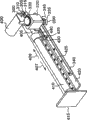
Fig. 4 is to use the stereogram of an axle of the straight movable joint mechanism of Fig. 3 bidirectional clutch 180.This straight movable joint mechanism is the straight movable joint mechanism that bar 410 relative pedestals 420 move on arrow 406,407 directions, after the pedestal 415 in next joint, has linked several same articulation mechanism, and has been connected with grip part 200 (with reference to Fig. 2).
The power of importing when operative doctor 170 passes to by grip part 200 (with reference to Fig. 2) on the pedestal 415 in next joint, will be subjected on this joint along the power effect of arrow 406 or 407 directions so.If three position solenoids 400 keep bar 300 under the state of the bar 300a of solid line, the transmission of power of bidirectional clutch is cut off so, and axle 330 and pinion 335 can rotate freely.Pinion 335 like this, owing to can rotate freely motion on one side on one side on tooth bar 340, so corresponding with the power on acting on next joint pedestal 415, guidance 430 can move freely at line slideway 425 upper edge arrows 406 or 407 directions.
On the other hand, the power of establishing operative doctor 170 inputs passes to by grip part 200 (with reference to Fig. 2) on the pedestal 415 in next joint, and the masterpiece of arrow 406 directions is used for this joint.At this moment, make the words of input device 190 in the motion of arrow 406 directions, suppose dangerous field on the direction of the manipulator 110 of corresponding and motion with it or 130 so, and calculate by master controller 150 (with reference to Fig. 1) and can not make manipulator 110 or 130 in the motion of this direction, at this moment, master controller 150, send the signal that drives three position solenoids 400, make pole 315 motion and the transmission of power function of bidirectional clutch is continued, pinion 335 can not and can be rotated in arrow 350 directions in the rotation of arrow 345 directions.Thus, guidance 430 by the engagement of pinion 335 and tooth bar 340, can move on arrow 407 directions, but can not move in arrow 406 directions.Therefore, operative doctor 170 can be imported at the enterprising line operate of arrow 407 directions of secure side, but can not operate input towards arrow 406 directions in dangerous field, thereby can solve the problem that manipulator 110 or 130 is moved to dangerous field.
Equally, if the masterpiece of arrow 407 directions is used for the pedestal 415 in next joint, at this moment, if make input device 190 move to words on arrow 407 directions, be located at it dangerous field on the manipulator 110 of corresponding and motion or 130 the direction so, and calculate by master controller 150 (with reference to Fig. 1) and can not make manipulator in this direction motion.At this moment, master controller 150 sends the signal that drives three position solenoids 400, makes pole 315 motions and the transmission of power function of bidirectional clutch is continued, and pinion 335 can not and can be rotated in arrow 345 directions in the rotation of arrow 350 directions.Thus, guidance 430 by the engagement of pinion 335 and tooth bar 340, can move on arrow 406 directions, but can not move in arrow 407 directions.
In addition, though do not show among the figure that the amount of movement in this joint can be measured by linear encoder, and available master controller 150 is obtained the operation input quantity.
Fig. 5 is the figure that input device 190 overall pictures of this example behind the operation table 240 have been omitted in expression.
The fixture 530 that is installed on the bar 535 continues between axle 525 and connecting rod 520, and connecting rod 520 becomes rotary joint between axle 525.Connecting rod 520 continues axle 515 as rotating shaft and connecting rod 510, connecting rod 510 continues between axle 505 and grip part 200.
The input device 190 of Fig. 5 is made of three straight movable joint and three rotary joints, and operative doctor can be imported six posture frees degree.In addition, grip part 200 has the switching joint of the illustrated surgical instrument of Fig. 6.
On the straight movable joint corresponding with arrow 563,537, for the deadweight of compensating operation input unit, disposed do not show among the figure decide the load spring.Therefore, operative doctor 170 is when catching grip part 220 to operate, and free operant is carried out in the deadweight of the input device 190 of can forgetting it.
In Fig. 5, on axle 525,515,505 as rotary joint, though do not represent direction of action restriction switching mechanism among the figure, but be fixed on the connecting rod of pedestal as joint shaft, housing 220 by axle 330 Fig. 3, and the connecting rod in next joint is fixed on the axle 330 to substitute pinion 350, then can realizes direction of action restriction switching mechanism.
In Fig. 5, by direction of action restriction switching mechanism only is used for three straight movable joint, can free input gestures, and only the position input is limited.Also can be by on three rotary joints, adding direction of action restriction switching mechanism, to limit the free degree of six postures.
Fig. 6 and Fig. 7 are the vertical views of the grip part 220 different operating states of this example of expression.In the symbol of the inscape that moves in grip part 200, indexing a represents under the state of Fig. 6, and indexing b represents under the state of Fig. 7, then omits subscript a~b when simultaneously each inscape being carried out general name and describes.
This grip part 200, be with forefinger and thumb by on fin 625,640, the mechanism that can import the opening and closing operations of surgical instrument 135.The characteristics of this grip part 200 are, pedestal 630 relatively, even only press fin 640, fin 625 also can symmetry move, and even press fin 625 on the contrary, fin 640 moves similarly.Thus, opening and closing operations can be fit to be accustomed to only only using with these three kinds of methods of human of two fingers with the people or the custom of forefinger with people, the custom of thumb.
With pedestal 630 all-in-one-piece cam chairs 605 on, formed the hole 606 that cam disc 610 can directly move.Axle 615 is central rotating shafts of fin 625,640, passes the axle that pedestal 630 becomes direction of action restriction switching mechanism 645.Axle 615, by the form of being arranged in advance rotate with fin 625 one, the angle that can utilize direction of action restriction switching mechanism 645 restriction fins to open and close.Direction of action restriction switching mechanism 645 comprises three position solenoids 600.In addition, also constitute and utilize among the figure encoder that does not show to obtain the angle that fin opens and closes.
In addition, axle 615 passes the cam hole 651 of cam disc 610.On the cam hole 651 of cam disc 610, pass respectively with fin 640 all-in-one-piece axles 650 with fin 625 all-in-one-piece axles 620.
In the stressed effect of closing direction, fin 640a is center rotation with axle 615 to the fin 640a of Fig. 6 so as Fig. 7 fin 640b, is integral with fin 640a and the axle 650a that moves is that pivot moves with axle 615 also.Axle 650a passes cam hole 651a and image pattern 7 cam disc 610b make the cam disc 610a of Fig. 6 move like that.Because cam disc 610a moves as cam disc 610b, by cam hole 651a axle 620a is applied the power of the direction that becomes a 620b, 625a becomes fin 625b with axle 620a all-in-one-piece fin.
In this example, owing to be the mechanism that simultaneously two fins is opened and closed, so compare with the mechanism of the common parallel rod of existing use etc., simple in structure, cost of manufacture is low.
In addition,, can limit gripping the size that opens and closes, perhaps keep closed state etc. by usage operation direction restriction switching mechanism 645.Using surgical instrument fin 640,625 to clamp or decontrol in the action of affected part, when the amount of surgical instrument 135 is opened in the hope restriction, can limit the size that surgical instrument fin 640,625 opens and closes, so help to improve security.In addition, owing to can keep closed state,, thus, reduced fatigue under the state of holding object such as pin so operative doctor 170 need not firmly be held with a firm grip.Also have, fin 640,625 utilizes the spring that does not show among the figure, is in open state shown in Figure 6 usually.
Open and close pedestal 630 and disposed microswitch 635, by firmly fin 640a being pressed into the state of 640b, microswitch 635 produces reaction.In this example, when constituting microswitch 635 reactions, direction of action restriction switching mechanism 645 works, and fin 640,625 remains on closed state.In addition, in order to remove the state of fin 640,625 closures, can realize by the other button that does not show in the figure below that press...withes one's finger.
When restriction surgical instrument switching amount, utilize the maximum switching amount of inputting interface 116 inputs in advance, usage operation direction restriction switching mechanism 645 is realized.
In addition, in direction of action restriction switching mechanism 645, continue direction and disconnection by with master controller 150 control transmission of power not only can show the wall in barrier and dangerous field, and pliability and hardness can point out mechanical arm to touch object in force feedback the time.That is to say, controller 150, cut-out by selecting transmission of power and the transmission of power direction that continues continues to switch subtly, the force feedback in the time of can pointing out the knee-joint of manipulator 110 or 130 to contact object.
As mentioned above, utilize this example, when not needing to point out situation such as security fields and dangerous field, can freely make input device 190 motions; When situations such as needs prompting security fields and dangerous field, can not use the motion of motor ground restriction, thereby can realize freely moving to the security fields direction to dangerous field direction.And input device 190 can not use motor ground to point out the actuating range and the barrier of restriction operative doctor in force feedback, and is very effective aspect miniaturization and control security, and can make the input device 190 of good operability.In addition, owing to there is not motor, reducing under the environment of noise effect in hope such as using the MRI device, is very effective.And then, owing to do not have motor, so low cost of manufacture.
In addition, in the opening and closing operations of surgical instrument 135, can also realize for example opening of restriction surgical instrument 135 in the action of clamping or decontroling by surgical instrument 135, perhaps alleviate the fatigue of firmly grasping grip part 200 when making surgical instrument 135 closures and causing, thereby can improve operability.
In addition, in this example,, also can use each two one-way clutch and solenoid to realize though used the disconnection and the mechanism that continues of bidirectional clutch as the transmission of power that realizes direction of action restriction switching mechanism.
In this example, having introduced the input device that manipulator is supported in operation, but the present invention can also be in addition practical as the input device of the arm of apery and the arm of device for industrial robot etc.
Claims (8)
1. master-slave mode arm-and-hand system possesses: have the manipulator of arm,
Input device, operator input is used to make the operation of the arm action of above-mentioned manipulator on this input device,
The controller that above-mentioned manipulator and aforesaid operations input unit are controlled,
Wherein, the aforesaid operations input unit possesses direction of action restriction switching mechanism on the joint, and this direction of action restriction switching mechanism has following pattern and selects one of them pattern and switch to selected pattern from a pattern, wherein
In a pattern, the action on direction on the joint is freely,
In another pattern, the action on direction on the joint is confined,
It is characterized in that, have the geometry information in the actuating range of the arm that can obtain above-mentioned manipulator and the sensor or the diagnostic device of obstacle information, and possesses basis by geometry information and obstacle information in the actuating range of the arm of the above-mentioned manipulator of the sensor or the detection of above-mentioned diagnostic device, the means that the movable field of the arm of above-mentioned manipulator is set, above-mentioned controller, when operate the arm of above-mentioned manipulator in the field that the arm of above-mentioned manipulator can not move, utilization is configured in the described direction of action restriction switching mechanism on each joint of aforesaid operations input unit, be limited in the immovable field operation of the arm aforesaid operations input unit of above-mentioned manipulator
The above-mentioned direction of action restriction switching mechanism that is configured on each joint of aforesaid operations input unit comprises bidirectional clutch.
2. master-slave mode arm-and-hand system as claimed in claim 1 is characterized in that, above-mentioned direction of action restriction switching mechanism also comprises the straight movable joint mechanism of three position solenoids and rack pinion.
3. master-slave mode arm-and-hand system as claimed in claim 1 or 2 is characterized in that, above-mentioned direction of action restriction switching mechanism also comprises three position solenoids and constitutes the rotary joint mechanism of two connecting rods in joint.
4. master-slave mode arm-and-hand system as claimed in claim 1 is characterized in that the aforesaid operations input unit possesses, and has the function of above-mentioned direction of action restriction switching mechanism, and can limit the gripping switching mechanism of the switching size of gripping arbitrarily.
5. master-slave mode arm-and-hand system as claimed in claim 1 is characterized in that, uses the diagnostic device of MRI device as geometry information in the actuating range of the arm of obtaining above-mentioned manipulator.
6. master-slave mode arm-and-hand system as claimed in claim 1 is characterized in that, the CT device is the diagnostic device as geometry information in the actuating range of the arm of obtaining above-mentioned manipulator.
7. master-slave mode arm-and-hand system as claimed in claim 1 is characterized in that, the selection that above-mentioned controller is controlled above-mentioned direction of action restriction switching mechanism is with the actuating range of the arm that limits above-mentioned manipulator.
8. master-slave mode arm-and-hand system as claimed in claim 1, it is characterized in that, above-mentioned controller, by repeatedly and with multiple duty ratio selecting above-mentioned direction of action to limit the pattern of switching mechanism, be used for switching subtly continuing, thus prompting force feedback when the arm contact object of above-mentioned manipulator.
Applications Claiming Priority (2)
| Application Number | Priority Date | Filing Date | Title |
|---|---|---|---|
| JP2005147786 | 2005-05-20 | ||
| JP2005147786A JP2006321027A (en) | 2005-05-20 | 2005-05-20 | Master slave type manipulator system and its operation input device |
Publications (2)
| Publication Number | Publication Date |
|---|---|
| CN1864938A CN1864938A (en) | 2006-11-22 |
| CN100522504C true CN100522504C (en) | 2009-08-05 |
Family
ID=36758241
Family Applications (1)
| Application Number | Title | Priority Date | Filing Date |
|---|---|---|---|
| CNB2006100824562A Expired - Fee Related CN100522504C (en) | 2005-05-20 | 2006-05-19 | Master-slave manipulator system and its operation input device |
Country Status (4)
| Country | Link |
|---|---|
| US (1) | US7391177B2 (en) |
| EP (1) | EP1724071A1 (en) |
| JP (1) | JP2006321027A (en) |
| CN (1) | CN100522504C (en) |
Families Citing this family (92)
| Publication number | Priority date | Publication date | Assignee | Title |
|---|---|---|---|---|
| US8944070B2 (en) | 1999-04-07 | 2015-02-03 | Intuitive Surgical Operations, Inc. | Non-force reflecting method for providing tool force information to a user of a telesurgical system |
| US9789608B2 (en) | 2006-06-29 | 2017-10-17 | Intuitive Surgical Operations, Inc. | Synthetic representation of a surgical robot |
| CN101291635B (en) * | 2005-10-20 | 2013-03-27 | 直观外科手术操作公司 | Auxiliary image display and manipulation on a computer display in a medical robotic system |
| US9060678B2 (en) * | 2006-06-13 | 2015-06-23 | Intuitive Surgical Operations, Inc. | Minimally invasive surgical system |
| US10008017B2 (en) | 2006-06-29 | 2018-06-26 | Intuitive Surgical Operations, Inc. | Rendering tool information as graphic overlays on displayed images of tools |
| US9718190B2 (en) | 2006-06-29 | 2017-08-01 | Intuitive Surgical Operations, Inc. | Tool position and identification indicator displayed in a boundary area of a computer display screen |
| US20090192523A1 (en) | 2006-06-29 | 2009-07-30 | Intuitive Surgical, Inc. | Synthetic representation of a surgical instrument |
| US10258425B2 (en) | 2008-06-27 | 2019-04-16 | Intuitive Surgical Operations, Inc. | Medical robotic system providing an auxiliary view of articulatable instruments extending out of a distal end of an entry guide |
| JP4911701B2 (en) | 2007-01-19 | 2012-04-04 | 株式会社日立製作所 | Master / slave manipulator system |
| JP4891823B2 (en) * | 2007-03-29 | 2012-03-07 | オリンパスメディカルシステムズ株式会社 | Endoscope device |
| US8903546B2 (en) | 2009-08-15 | 2014-12-02 | Intuitive Surgical Operations, Inc. | Smooth control of an articulated instrument across areas with different work space conditions |
| US9084623B2 (en) | 2009-08-15 | 2015-07-21 | Intuitive Surgical Operations, Inc. | Controller assisted reconfiguration of an articulated instrument during movement into and out of an entry guide |
| US8620473B2 (en) | 2007-06-13 | 2013-12-31 | Intuitive Surgical Operations, Inc. | Medical robotic system with coupled control modes |
| US9138129B2 (en) | 2007-06-13 | 2015-09-22 | Intuitive Surgical Operations, Inc. | Method and system for moving a plurality of articulated instruments in tandem back towards an entry guide |
| US9089256B2 (en) | 2008-06-27 | 2015-07-28 | Intuitive Surgical Operations, Inc. | Medical robotic system providing an auxiliary view including range of motion limitations for articulatable instruments extending out of a distal end of an entry guide |
| US9469034B2 (en) | 2007-06-13 | 2016-10-18 | Intuitive Surgical Operations, Inc. | Method and system for switching modes of a robotic system |
| JP5209903B2 (en) * | 2007-06-18 | 2013-06-12 | オリンパスメディカルシステムズ株式会社 | Power transmission device for electric bending endoscope |
| JP5024763B2 (en) * | 2007-11-30 | 2012-09-12 | 国立大学法人 東京大学 | Master manipulator used in surgery support system |
| US8864652B2 (en) * | 2008-06-27 | 2014-10-21 | Intuitive Surgical Operations, Inc. | Medical robotic system providing computer generated auxiliary views of a camera instrument for controlling the positioning and orienting of its tip |
| US8332072B1 (en) | 2008-08-22 | 2012-12-11 | Titan Medical Inc. | Robotic hand controller |
| US8918211B2 (en) | 2010-02-12 | 2014-12-23 | Intuitive Surgical Operations, Inc. | Medical robotic system providing sensory feedback indicating a difference between a commanded state and a preferred pose of an articulated instrument |
| US9492927B2 (en) | 2009-08-15 | 2016-11-15 | Intuitive Surgical Operations, Inc. | Application of force feedback on an input device to urge its operator to command an articulated instrument to a preferred pose |
| CN103237633B (en) * | 2010-11-30 | 2015-07-22 | 奥林巴斯株式会社 | Master control input device and master-lave manipulator |
| US9119655B2 (en) | 2012-08-03 | 2015-09-01 | Stryker Corporation | Surgical manipulator capable of controlling a surgical instrument in multiple modes |
| JP5669590B2 (en) * | 2011-01-20 | 2015-02-12 | オリンパス株式会社 | Master-slave manipulator and medical master-slave manipulator |
| JP2012171088A (en) * | 2011-02-24 | 2012-09-10 | Olympus Corp | Master operation input device, and master-slave manipulator |
| WO2012170256A1 (en) * | 2011-05-31 | 2012-12-13 | Intuitive Surgical Operations, Inc. | Positive control of robotic surgical instrument end effector |
| EP2732344B1 (en) * | 2011-07-11 | 2019-06-05 | Board of Regents of the University of Nebraska | Robotic surgical system |
| JP6009840B2 (en) | 2011-08-04 | 2016-10-19 | オリンパス株式会社 | Medical equipment |
| JP5855656B2 (en) * | 2011-08-04 | 2016-02-09 | オリンパス株式会社 | Medical manipulator and method of operating the same |
| JP6081061B2 (en) | 2011-08-04 | 2017-02-15 | オリンパス株式会社 | Surgery support device |
| CN103732173B (en) | 2011-08-04 | 2016-03-09 | 奥林巴斯株式会社 | Surgical instrument and medical manipulator |
| EP2740435B8 (en) | 2011-08-04 | 2018-12-19 | Olympus Corporation | Surgical support apparatus |
| JP6005950B2 (en) | 2011-08-04 | 2016-10-12 | オリンパス株式会社 | Surgery support apparatus and control method thereof |
| JP5936914B2 (en) | 2011-08-04 | 2016-06-22 | オリンパス株式会社 | Operation input device and manipulator system including the same |
| JP6021353B2 (en) | 2011-08-04 | 2016-11-09 | オリンパス株式会社 | Surgery support device |
| EP2740434A4 (en) | 2011-08-04 | 2015-03-18 | Olympus Corp | Medical manipulator and method for controlling same |
| JP5841451B2 (en) | 2011-08-04 | 2016-01-13 | オリンパス株式会社 | Surgical instrument and control method thereof |
| JP6000641B2 (en) | 2011-08-04 | 2016-10-05 | オリンパス株式会社 | Manipulator system |
| JP6021484B2 (en) | 2011-08-04 | 2016-11-09 | オリンパス株式会社 | Medical manipulator |
| JP5931497B2 (en) | 2011-08-04 | 2016-06-08 | オリンパス株式会社 | Surgery support apparatus and assembly method thereof |
| JP5953058B2 (en) | 2011-08-04 | 2016-07-13 | オリンパス株式会社 | Surgery support device and method for attaching and detaching the same |
| CN106725857B (en) * | 2012-02-15 | 2019-06-07 | 直观外科手术操作公司 | Robot system |
| EP2844181B1 (en) | 2012-05-01 | 2021-03-10 | Board of Regents of the University of Nebraska | Single site robotic device and related systems |
| WO2014022786A2 (en) | 2012-08-03 | 2014-02-06 | Stryker Corporation | Systems and methods for robotic surgery |
| US9226796B2 (en) | 2012-08-03 | 2016-01-05 | Stryker Corporation | Method for detecting a disturbance as an energy applicator of a surgical instrument traverses a cutting path |
| EP2882331A4 (en) | 2012-08-08 | 2016-03-23 | Univ Nebraska | Robotic surgical devices, systems, and related methods |
| CN103085055B (en) * | 2013-01-29 | 2016-06-22 | 山东电力集团公司电力科学研究院 | Hot-line repair robot position feedback master system |
| US10507066B2 (en) | 2013-02-15 | 2019-12-17 | Intuitive Surgical Operations, Inc. | Providing information of tools by filtering image areas adjacent to or on displayed images of the tools |
| JP6132904B2 (en) * | 2013-03-29 | 2017-05-24 | オリンパス株式会社 | Master-slave system and its operation method |
| CA2918531A1 (en) | 2013-07-17 | 2015-01-22 | Board Of Regents Of The University Of Nebraska | Robotic surgical devices, systems and related methods |
| JP6164964B2 (en) * | 2013-07-26 | 2017-07-19 | オリンパス株式会社 | Medical system and control method thereof |
| JP6358463B2 (en) * | 2013-11-13 | 2018-07-18 | パナソニックIpマネジメント株式会社 | Master device for master-slave device, control method therefor, and master-slave device |
| KR102327948B1 (en) * | 2014-03-17 | 2021-11-17 | 인튜어티브 서지컬 오퍼레이션즈 인코포레이티드 | Structural adjustment systems and methods for a teleoperational medical system |
| KR102455799B1 (en) * | 2014-03-31 | 2022-10-18 | 인튜어티브 서지컬 오퍼레이션즈 인코포레이티드 | Surgical instrument with shiftable transmission |
| WO2015153636A1 (en) * | 2014-04-01 | 2015-10-08 | Intuitive Surgical Operations, Inc. | Control input accuracy for teleoperated surgical instrument |
| CN109512516B (en) * | 2014-04-24 | 2021-12-14 | 柯惠Lp公司 | Robot interface positioning determination system and method |
| EP3177436B1 (en) * | 2014-08-08 | 2018-12-26 | BBZ S.r.l. | Remote manipulation input device |
| US9592608B1 (en) | 2014-12-15 | 2017-03-14 | X Development Llc | Methods and systems for providing feedback during teach mode |
| US10582979B2 (en) | 2015-03-26 | 2020-03-10 | Covidien Lp | Input device assemblies for robotic surgical systems |
| CN113017841A (en) | 2015-06-16 | 2021-06-25 | 提坦医疗公司 | Handle apparatus for receiving operator input in a robotic surgical system |
| JP6520478B2 (en) * | 2015-06-30 | 2019-05-29 | 株式会社デンソーウェーブ | Robot arm operation system |
| CA2994823A1 (en) | 2015-08-03 | 2017-02-09 | Board Of Regents Of The University Of Nebraska | Robotic surgical devices, systems and related methods |
| US11351001B2 (en) | 2015-08-17 | 2022-06-07 | Intuitive Surgical Operations, Inc. | Ungrounded master control devices and methods of use |
| WO2017070266A1 (en) * | 2015-10-22 | 2017-04-27 | Covidien Lp | Variable sweeping for input devices |
| JP6660157B2 (en) * | 2015-11-16 | 2020-03-11 | 川崎重工業株式会社 | Robot and work method by robot |
| US9919422B1 (en) * | 2016-01-06 | 2018-03-20 | X Development Llc | Methods and systems to provide mechanical feedback during movement of a robotic system |
| WO2017146890A1 (en) | 2016-02-26 | 2017-08-31 | Intuitive Surgical Operations, Inc. | System and method for collision avoidance using virtual boundaries |
| JP2017176307A (en) * | 2016-03-29 | 2017-10-05 | ソニー株式会社 | Control unit of medical support arm, control method of medical support arm device, and medical system |
| TWI595986B (en) * | 2016-04-19 | 2017-08-21 | Hiwin Tech Corp | Endoscopic movement control method driven by a mechanical arm |
| JP7176757B2 (en) | 2016-05-18 | 2022-11-22 | バーチャル インシジョン コーポレイション | ROBOTIC SURGICAL DEVICES, SYSTEMS AND RELATED METHODS |
| CN107708594B (en) | 2016-06-03 | 2021-03-05 | 柯惠Lp公司 | Control arm assembly for robotic surgical system |
| WO2017210499A1 (en) * | 2016-06-03 | 2017-12-07 | Covidien Lp | Control arm for robotic surgical systems |
| CN114504387A (en) | 2016-06-03 | 2022-05-17 | 柯惠Lp公司 | Passive shaft system for robotic surgical system |
| EP3554414A1 (en) | 2016-12-16 | 2019-10-23 | MAKO Surgical Corp. | Techniques for modifying tool operation in a surgical robotic system based on comparing actual and commanded states of the tool relative to a surgical site |
| JP2018198750A (en) * | 2017-05-26 | 2018-12-20 | ソニー株式会社 | Medical system, control device for medical support arm, and control method for medical support arm |
| EP3709923A4 (en) * | 2017-11-15 | 2021-08-11 | Intuitive Surgical Operations, Inc. | Master control device with multi-finger grip and methods therefor |
| US11712314B2 (en) | 2017-11-15 | 2023-08-01 | Intuitive Surgical Operations, Inc. | Master control device and methods therefor |
| JP6936712B2 (en) * | 2017-11-24 | 2021-09-22 | 川崎重工業株式会社 | Operating device |
| CN117140580A (en) | 2018-01-05 | 2023-12-01 | 内布拉斯加大学董事会 | Single arm robotic device with compact joint design and related systems and methods |
| US10758311B2 (en) * | 2018-10-30 | 2020-09-01 | Titan Medical Inc. | Hand controller apparatus for gesture control and shared input control in a robotic surgery system |
| US11166769B2 (en) | 2018-10-30 | 2021-11-09 | Titan Medical Inc. | Hand controller apparatus with feedback responsive to function change in a robotic surgery system |
| US10426561B1 (en) | 2018-10-30 | 2019-10-01 | Titan Medical Inc. | Hand controller apparatus for detecting input position in a robotic surgery system |
| US11116591B2 (en) | 2018-10-30 | 2021-09-14 | Titan Medical Inc. | Hand controller apparatus including ergonomic features for a robotic surgery system |
| US11903658B2 (en) | 2019-01-07 | 2024-02-20 | Virtual Incision Corporation | Robotically assisted surgical system and related devices and methods |
| JP2020049300A (en) * | 2019-12-25 | 2020-04-02 | 株式会社メディカロイド | Remote handling equipment and remote surgery system |
| KR102261262B1 (en) * | 2020-04-22 | 2021-06-07 | 주식회사 이지엔도서지컬 | Master device for controlling an slave device |
| CN111730598B (en) * | 2020-07-06 | 2022-01-04 | 武汉联影智融医疗科技有限公司 | Robot force position interlocking control method, device and system |
| CN112716608B (en) * | 2021-01-20 | 2022-06-24 | 山东威高手术机器人有限公司 | Master-slave tracking control method for minimally invasive surgery robot |
| WO2023112732A1 (en) * | 2021-12-13 | 2023-06-22 | ソニーグループ株式会社 | Robot system and coordinate registration method |
| CN114789432B (en) * | 2022-03-31 | 2023-08-29 | 西安交通大学 | Double-arm robot manpower-position hybrid control method for building board installation |
| CN114770458B (en) * | 2022-04-28 | 2023-09-15 | 燕山大学 | Master-slave bidirectional control method and system for redundancy degree-of-freedom teleoperation robot |
Citations (3)
| Publication number | Priority date | Publication date | Assignee | Title |
|---|---|---|---|---|
| US5399951A (en) * | 1992-05-12 | 1995-03-21 | Universite Joseph Fourier | Robot for guiding movements and control method thereof |
| US6233504B1 (en) * | 1998-04-16 | 2001-05-15 | California Institute Of Technology | Tool actuation and force feedback on robot-assisted microsurgery system |
| US6437771B1 (en) * | 1995-01-18 | 2002-08-20 | Immersion Corporation | Force feedback device including flexure member between actuator and user object |
Family Cites Families (10)
| Publication number | Priority date | Publication date | Assignee | Title |
|---|---|---|---|---|
| US5672044A (en) * | 1974-01-24 | 1997-09-30 | Lemelson; Jerome H. | Free-traveling manipulator with powered tools |
| JP2567198B2 (en) | 1993-10-29 | 1996-12-25 | 株式会社明電舎 | Master-slave type manipulator |
| US5792135A (en) * | 1996-05-20 | 1998-08-11 | Intuitive Surgical, Inc. | Articulated surgical instrument for performing minimally invasive surgery with enhanced dexterity and sensitivity |
| JP3178813B2 (en) | 1998-05-29 | 2001-06-25 | 川崎重工業株式会社 | Remote control device |
| JP4656700B2 (en) * | 2000-07-11 | 2011-03-23 | オリンパス株式会社 | Endoscopic surgery system |
| US7831292B2 (en) * | 2002-03-06 | 2010-11-09 | Mako Surgical Corp. | Guidance system and method for surgical procedures with improved feedback |
| JP2003299674A (en) * | 2002-04-12 | 2003-10-21 | Masasuke Shiraishi | Operation table device |
| JP3912251B2 (en) | 2002-10-02 | 2007-05-09 | 株式会社日立製作所 | manipulator |
| JP2004223128A (en) * | 2003-01-27 | 2004-08-12 | Hitachi Ltd | Medical practice supporting apparatus and method |
| JP2005030451A (en) * | 2003-07-08 | 2005-02-03 | Alps Electric Co Ltd | Kinesthetic sense application type input device |
-
2005
- 2005-05-20 JP JP2005147786A patent/JP2006321027A/en active Pending
-
2006
- 2006-05-17 US US11/434,900 patent/US7391177B2/en active Active
- 2006-05-19 CN CNB2006100824562A patent/CN100522504C/en not_active Expired - Fee Related
- 2006-05-19 EP EP06010411A patent/EP1724071A1/en not_active Withdrawn
Patent Citations (3)
| Publication number | Priority date | Publication date | Assignee | Title |
|---|---|---|---|---|
| US5399951A (en) * | 1992-05-12 | 1995-03-21 | Universite Joseph Fourier | Robot for guiding movements and control method thereof |
| US6437771B1 (en) * | 1995-01-18 | 2002-08-20 | Immersion Corporation | Force feedback device including flexure member between actuator and user object |
| US6233504B1 (en) * | 1998-04-16 | 2001-05-15 | California Institute Of Technology | Tool actuation and force feedback on robot-assisted microsurgery system |
Also Published As
| Publication number | Publication date |
|---|---|
| CN1864938A (en) | 2006-11-22 |
| EP1724071A1 (en) | 2006-11-22 |
| US20060261770A1 (en) | 2006-11-23 |
| JP2006321027A (en) | 2006-11-30 |
| US7391177B2 (en) | 2008-06-24 |
Similar Documents
| Publication | Publication Date | Title |
|---|---|---|
| CN100522504C (en) | Master-slave manipulator system and its operation input device | |
| US20230240775A1 (en) | Actuated grips for controller | |
| US20200330172A1 (en) | Methods, Systems, and Devices Relating to Force Control Surgical Systems | |
| US6233504B1 (en) | Tool actuation and force feedback on robot-assisted microsurgery system | |
| Tavakoli et al. | A force reflective master-slave system for minimally invasive surgery | |
| US20220015852A1 (en) | User interface device having grip linkages | |
| JP2002059380A (en) | Master-slave device | |
| JP2013034851A (en) | Manipulator system | |
| Hadavand et al. | A novel remote center of motion mechanism for the force‐reflective master robot of haptic tele‐surgery systems | |
| US11730556B2 (en) | Compact actuation configuration and expandable instrument receiver for robotically controlled surgical instruments | |
| WO2019039612A2 (en) | Forceps system | |
| US20210251707A1 (en) | Control switch position sensing across a rotational joint | |
| Shim et al. | An all-joint-control master device for single-port laparoscopic surgery robots | |
| US20220104892A1 (en) | Actuation carriage with integrated measurement for robotically controlled surgical instruments | |
| JP4346615B2 (en) | Medical manipulator | |
| EP3787852B1 (en) | User interface device having grip linkages | |
| Li et al. | Haptic device with gripping force feedback | |
| EP3998980A1 (en) | Compact actuation configuration and expandable instrument receiver for robotically controlled surgical instruments | |
| Bleuler et al. | Trends in surgical robotics | |
| Gosselin | Modern devices for telesurgery | |
| Ishii et al. | Lyapunov function based bilateral control for teleoperation system with time varying delay | |
| Prasanga et al. | Achievement of real haptic sensation with tendon driven segregated jaws for laparoscopic forceps | |
| Agarwal et al. | Additive Manufacturing and Series Elastic Actuation for Hand Exoskeletons | |
| Zhang et al. | Application research of telesurgical robot control system with force feedback device | |
| MICROSURGERY | I11111 111111ll Ill11 Ill11 IIIII 11111 IIIII IIIII IIIII Ill11 11ll1111ll11l111 |
Legal Events
| Date | Code | Title | Description |
|---|---|---|---|
| C06 | Publication | ||
| PB01 | Publication | ||
| C10 | Entry into substantive examination | ||
| SE01 | Entry into force of request for substantive examination | ||
| C14 | Grant of patent or utility model | ||
| GR01 | Patent grant | ||
| CF01 | Termination of patent right due to non-payment of annual fee |
Granted publication date: 20090805 |
|
| CF01 | Termination of patent right due to non-payment of annual fee |