CN100489637C - Components and methods for use in electro-optic displays - Google Patents
Components and methods for use in electro-optic displays Download PDFInfo
- Publication number
- CN100489637C CN100489637C CNB038134543A CN03813454A CN100489637C CN 100489637 C CN100489637 C CN 100489637C CN B038134543 A CNB038134543 A CN B038134543A CN 03813454 A CN03813454 A CN 03813454A CN 100489637 C CN100489637 C CN 100489637C
- Authority
- CN
- China
- Prior art keywords
- electro
- layer
- optic medium
- conductive
- conductive layer
- Prior art date
- Legal status (The legal status is an assumption and is not a legal conclusion. Google has not performed a legal analysis and makes no representation as to the accuracy of the status listed.)
- Expired - Lifetime
Links
Images


Classifications
-
- B—PERFORMING OPERATIONS; TRANSPORTING
- B05—SPRAYING OR ATOMISING IN GENERAL; APPLYING FLUENT MATERIALS TO SURFACES, IN GENERAL
- B05D—PROCESSES FOR APPLYING FLUENT MATERIALS TO SURFACES, IN GENERAL
- B05D7/00—Processes, other than flocking, specially adapted for applying liquids or other fluent materials to particular surfaces or for applying particular liquids or other fluent materials
- B05D7/50—Multilayers
- B05D7/52—Two layers
- B05D7/54—No clear coat specified
- B05D7/548—No curing step for the last layer
- B05D7/5483—No curing step for any layer
-
- G—PHYSICS
- G02—OPTICS
- G02F—OPTICAL DEVICES OR ARRANGEMENTS FOR THE CONTROL OF LIGHT BY MODIFICATION OF THE OPTICAL PROPERTIES OF THE MEDIA OF THE ELEMENTS INVOLVED THEREIN; NON-LINEAR OPTICS; FREQUENCY-CHANGING OF LIGHT; OPTICAL LOGIC ELEMENTS; OPTICAL ANALOGUE/DIGITAL CONVERTERS
- G02F1/00—Devices or arrangements for the control of the intensity, colour, phase, polarisation or direction of light arriving from an independent light source, e.g. switching, gating or modulating; Non-linear optics
- G02F1/01—Devices or arrangements for the control of the intensity, colour, phase, polarisation or direction of light arriving from an independent light source, e.g. switching, gating or modulating; Non-linear optics for the control of the intensity, phase, polarisation or colour
- G02F1/165—Devices or arrangements for the control of the intensity, colour, phase, polarisation or direction of light arriving from an independent light source, e.g. switching, gating or modulating; Non-linear optics for the control of the intensity, phase, polarisation or colour based on translational movement of particles in a fluid under the influence of an applied field
- G02F1/166—Devices or arrangements for the control of the intensity, colour, phase, polarisation or direction of light arriving from an independent light source, e.g. switching, gating or modulating; Non-linear optics for the control of the intensity, phase, polarisation or colour based on translational movement of particles in a fluid under the influence of an applied field characterised by the electro-optical or magneto-optical effect
- G02F1/167—Devices or arrangements for the control of the intensity, colour, phase, polarisation or direction of light arriving from an independent light source, e.g. switching, gating or modulating; Non-linear optics for the control of the intensity, phase, polarisation or colour based on translational movement of particles in a fluid under the influence of an applied field characterised by the electro-optical or magneto-optical effect by electrophoresis
-
- B—PERFORMING OPERATIONS; TRANSPORTING
- B32—LAYERED PRODUCTS
- B32B—LAYERED PRODUCTS, i.e. PRODUCTS BUILT-UP OF STRATA OF FLAT OR NON-FLAT, e.g. CELLULAR OR HONEYCOMB, FORM
- B32B37/00—Methods or apparatus for laminating, e.g. by curing or by ultrasonic bonding
- B32B37/12—Methods or apparatus for laminating, e.g. by curing or by ultrasonic bonding characterised by using adhesives
-
- B—PERFORMING OPERATIONS; TRANSPORTING
- B32—LAYERED PRODUCTS
- B32B—LAYERED PRODUCTS, i.e. PRODUCTS BUILT-UP OF STRATA OF FLAT OR NON-FLAT, e.g. CELLULAR OR HONEYCOMB, FORM
- B32B37/00—Methods or apparatus for laminating, e.g. by curing or by ultrasonic bonding
- B32B37/14—Methods or apparatus for laminating, e.g. by curing or by ultrasonic bonding characterised by the properties of the layers
- B32B37/16—Methods or apparatus for laminating, e.g. by curing or by ultrasonic bonding characterised by the properties of the layers with all layers existing as coherent layers before laminating
- B32B37/18—Methods or apparatus for laminating, e.g. by curing or by ultrasonic bonding characterised by the properties of the layers with all layers existing as coherent layers before laminating involving the assembly of discrete sheets or panels only
-
- G—PHYSICS
- G02—OPTICS
- G02B—OPTICAL ELEMENTS, SYSTEMS OR APPARATUS
- G02B1/00—Optical elements characterised by the material of which they are made; Optical coatings for optical elements
- G02B1/10—Optical coatings produced by application to, or surface treatment of, optical elements
- G02B1/14—Protective coatings, e.g. hard coatings
-
- G—PHYSICS
- G02—OPTICS
- G02F—OPTICAL DEVICES OR ARRANGEMENTS FOR THE CONTROL OF LIGHT BY MODIFICATION OF THE OPTICAL PROPERTIES OF THE MEDIA OF THE ELEMENTS INVOLVED THEREIN; NON-LINEAR OPTICS; FREQUENCY-CHANGING OF LIGHT; OPTICAL LOGIC ELEMENTS; OPTICAL ANALOGUE/DIGITAL CONVERTERS
- G02F1/00—Devices or arrangements for the control of the intensity, colour, phase, polarisation or direction of light arriving from an independent light source, e.g. switching, gating or modulating; Non-linear optics
- G02F1/01—Devices or arrangements for the control of the intensity, colour, phase, polarisation or direction of light arriving from an independent light source, e.g. switching, gating or modulating; Non-linear optics for the control of the intensity, phase, polarisation or colour
- G02F1/13—Devices or arrangements for the control of the intensity, colour, phase, polarisation or direction of light arriving from an independent light source, e.g. switching, gating or modulating; Non-linear optics for the control of the intensity, phase, polarisation or colour based on liquid crystals, e.g. single liquid crystal display cells
- G02F1/1306—Details
- G02F1/1309—Repairing; Testing
-
- G—PHYSICS
- G02—OPTICS
- G02F—OPTICAL DEVICES OR ARRANGEMENTS FOR THE CONTROL OF LIGHT BY MODIFICATION OF THE OPTICAL PROPERTIES OF THE MEDIA OF THE ELEMENTS INVOLVED THEREIN; NON-LINEAR OPTICS; FREQUENCY-CHANGING OF LIGHT; OPTICAL LOGIC ELEMENTS; OPTICAL ANALOGUE/DIGITAL CONVERTERS
- G02F1/00—Devices or arrangements for the control of the intensity, colour, phase, polarisation or direction of light arriving from an independent light source, e.g. switching, gating or modulating; Non-linear optics
- G02F1/01—Devices or arrangements for the control of the intensity, colour, phase, polarisation or direction of light arriving from an independent light source, e.g. switching, gating or modulating; Non-linear optics for the control of the intensity, phase, polarisation or colour
- G02F1/13—Devices or arrangements for the control of the intensity, colour, phase, polarisation or direction of light arriving from an independent light source, e.g. switching, gating or modulating; Non-linear optics for the control of the intensity, phase, polarisation or colour based on liquid crystals, e.g. single liquid crystal display cells
- G02F1/133—Constructional arrangements; Operation of liquid crystal cells; Circuit arrangements
- G02F1/1333—Constructional arrangements; Manufacturing methods
- G02F1/1339—Gaskets; Spacers; Sealing of cells
-
- G—PHYSICS
- G02—OPTICS
- G02F—OPTICAL DEVICES OR ARRANGEMENTS FOR THE CONTROL OF LIGHT BY MODIFICATION OF THE OPTICAL PROPERTIES OF THE MEDIA OF THE ELEMENTS INVOLVED THEREIN; NON-LINEAR OPTICS; FREQUENCY-CHANGING OF LIGHT; OPTICAL LOGIC ELEMENTS; OPTICAL ANALOGUE/DIGITAL CONVERTERS
- G02F1/00—Devices or arrangements for the control of the intensity, colour, phase, polarisation or direction of light arriving from an independent light source, e.g. switching, gating or modulating; Non-linear optics
- G02F1/01—Devices or arrangements for the control of the intensity, colour, phase, polarisation or direction of light arriving from an independent light source, e.g. switching, gating or modulating; Non-linear optics for the control of the intensity, phase, polarisation or colour
- G02F1/165—Devices or arrangements for the control of the intensity, colour, phase, polarisation or direction of light arriving from an independent light source, e.g. switching, gating or modulating; Non-linear optics for the control of the intensity, phase, polarisation or colour based on translational movement of particles in a fluid under the influence of an applied field
- G02F1/1675—Constructional details
-
- B—PERFORMING OPERATIONS; TRANSPORTING
- B32—LAYERED PRODUCTS
- B32B—LAYERED PRODUCTS, i.e. PRODUCTS BUILT-UP OF STRATA OF FLAT OR NON-FLAT, e.g. CELLULAR OR HONEYCOMB, FORM
- B32B2307/00—Properties of the layers or laminate
- B32B2307/20—Properties of the layers or laminate having particular electrical or magnetic properties, e.g. piezoelectric
- B32B2307/202—Conductive
-
- B—PERFORMING OPERATIONS; TRANSPORTING
- B32—LAYERED PRODUCTS
- B32B—LAYERED PRODUCTS, i.e. PRODUCTS BUILT-UP OF STRATA OF FLAT OR NON-FLAT, e.g. CELLULAR OR HONEYCOMB, FORM
- B32B2457/00—Electrical equipment
- B32B2457/20—Displays, e.g. liquid crystal displays, plasma displays
-
- G—PHYSICS
- G02—OPTICS
- G02F—OPTICAL DEVICES OR ARRANGEMENTS FOR THE CONTROL OF LIGHT BY MODIFICATION OF THE OPTICAL PROPERTIES OF THE MEDIA OF THE ELEMENTS INVOLVED THEREIN; NON-LINEAR OPTICS; FREQUENCY-CHANGING OF LIGHT; OPTICAL LOGIC ELEMENTS; OPTICAL ANALOGUE/DIGITAL CONVERTERS
- G02F1/00—Devices or arrangements for the control of the intensity, colour, phase, polarisation or direction of light arriving from an independent light source, e.g. switching, gating or modulating; Non-linear optics
- G02F1/01—Devices or arrangements for the control of the intensity, colour, phase, polarisation or direction of light arriving from an independent light source, e.g. switching, gating or modulating; Non-linear optics for the control of the intensity, phase, polarisation or colour
- G02F1/165—Devices or arrangements for the control of the intensity, colour, phase, polarisation or direction of light arriving from an independent light source, e.g. switching, gating or modulating; Non-linear optics for the control of the intensity, phase, polarisation or colour based on translational movement of particles in a fluid under the influence of an applied field
- G02F1/1675—Constructional details
- G02F1/1679—Gaskets; Spacers; Sealing of cells; Filling or closing of cells
- G02F1/1681—Gaskets; Spacers; Sealing of cells; Filling or closing of cells having two or more microcells partitioned by walls, e.g. of microcup type
-
- G—PHYSICS
- G02—OPTICS
- G02F—OPTICAL DEVICES OR ARRANGEMENTS FOR THE CONTROL OF LIGHT BY MODIFICATION OF THE OPTICAL PROPERTIES OF THE MEDIA OF THE ELEMENTS INVOLVED THEREIN; NON-LINEAR OPTICS; FREQUENCY-CHANGING OF LIGHT; OPTICAL LOGIC ELEMENTS; OPTICAL ANALOGUE/DIGITAL CONVERTERS
- G02F1/00—Devices or arrangements for the control of the intensity, colour, phase, polarisation or direction of light arriving from an independent light source, e.g. switching, gating or modulating; Non-linear optics
- G02F1/01—Devices or arrangements for the control of the intensity, colour, phase, polarisation or direction of light arriving from an independent light source, e.g. switching, gating or modulating; Non-linear optics for the control of the intensity, phase, polarisation or colour
- G02F1/165—Devices or arrangements for the control of the intensity, colour, phase, polarisation or direction of light arriving from an independent light source, e.g. switching, gating or modulating; Non-linear optics for the control of the intensity, phase, polarisation or colour based on translational movement of particles in a fluid under the influence of an applied field
- G02F1/1675—Constructional details
- G02F2001/1678—Constructional details characterised by the composition or particle type
-
- G—PHYSICS
- G02—OPTICS
- G02F—OPTICAL DEVICES OR ARRANGEMENTS FOR THE CONTROL OF LIGHT BY MODIFICATION OF THE OPTICAL PROPERTIES OF THE MEDIA OF THE ELEMENTS INVOLVED THEREIN; NON-LINEAR OPTICS; FREQUENCY-CHANGING OF LIGHT; OPTICAL LOGIC ELEMENTS; OPTICAL ANALOGUE/DIGITAL CONVERTERS
- G02F2202/00—Materials and properties
- G02F2202/28—Adhesive materials or arrangements
-
- G—PHYSICS
- G02—OPTICS
- G02F—OPTICAL DEVICES OR ARRANGEMENTS FOR THE CONTROL OF LIGHT BY MODIFICATION OF THE OPTICAL PROPERTIES OF THE MEDIA OF THE ELEMENTS INVOLVED THEREIN; NON-LINEAR OPTICS; FREQUENCY-CHANGING OF LIGHT; OPTICAL LOGIC ELEMENTS; OPTICAL ANALOGUE/DIGITAL CONVERTERS
- G02F2203/00—Function characteristic
- G02F2203/69—Arrangements or methods for testing or calibrating a device
-
- Y—GENERAL TAGGING OF NEW TECHNOLOGICAL DEVELOPMENTS; GENERAL TAGGING OF CROSS-SECTIONAL TECHNOLOGIES SPANNING OVER SEVERAL SECTIONS OF THE IPC; TECHNICAL SUBJECTS COVERED BY FORMER USPC CROSS-REFERENCE ART COLLECTIONS [XRACs] AND DIGESTS
- Y10—TECHNICAL SUBJECTS COVERED BY FORMER USPC
- Y10T—TECHNICAL SUBJECTS COVERED BY FORMER US CLASSIFICATION
- Y10T156/00—Adhesive bonding and miscellaneous chemical manufacture
- Y10T156/10—Methods of surface bonding and/or assembly therefor
-
- Y—GENERAL TAGGING OF NEW TECHNOLOGICAL DEVELOPMENTS; GENERAL TAGGING OF CROSS-SECTIONAL TECHNOLOGIES SPANNING OVER SEVERAL SECTIONS OF THE IPC; TECHNICAL SUBJECTS COVERED BY FORMER USPC CROSS-REFERENCE ART COLLECTIONS [XRACs] AND DIGESTS
- Y10—TECHNICAL SUBJECTS COVERED BY FORMER USPC
- Y10T—TECHNICAL SUBJECTS COVERED BY FORMER US CLASSIFICATION
- Y10T428/00—Stock material or miscellaneous articles
- Y10T428/14—Layer or component removable to expose adhesive
- Y10T428/1476—Release layer
Abstract
A front plane laminate (10) useful in the manufacture of electro-optic displays comprises, in order, a light-transmissive electrically-conductive layer (14), a layer (16) of an electro-optic medium in electrical contact with the electrically-conductive layer (14), an adhesive layer (26) and a release sheet (28). This front plane laminate (10) can be prepared as a continuous web, cut to size, the release sheet (28) removed and the laminate (10) laminated to a backplane to form a display. Methods for providing conductive vias through the electro-optic medium and for testing the front plane laminate are also described.
Description
The present invention relates to be used to form the process and the parts of Electro-Optical Display. more particularly, (this display hereinafter for convenience to the present invention relates to be used to form the Electro-Optical Display that contains solid-state electro-optic medium, be referred to as " solid-state Electro-Optical Display ") process and parts, usually this electro-optic medium has solid-state outside surface, although this medium may (having usually) have the space of internal liquid or gas filling, and relates to the method that the such electro-optic medium of use is come assembled display.Like this, term " solid-state Electro-Optical Display " comprises the electrophoretic display device (EPD) of encapsulation, the LCD of encapsulation and the display of other types to be discussed below.
As the term " photoelectricity " that in material or display, uses, what here use is its conventional sense in imaging field, refer to have first and second show states material of (there are differences aspect a kind of optical property at least), by applying electric field to material, this material changes to second show state from first show state.Although, usually optical property is perceptible on color for human eye, but also may be other optical property, such as light transmission rate, reflectivity, brightness or be used for the demonstration that machine is read in some cases, or the pseudo-colours of the reflectance varies that is arranged in the electromagnetic wavelength outside the visible-range under certain conditions.
Here the term of Shi Yonging " bistable state " and " bistability " are the implications in its traditional this area, refer to and comprise have first and second show states display of display element of (there are differences aspect a kind of optical property at least), make after the addressing pulse by the limited lasting cycle drives any point element, suppose and be in first or second show state, after addressing pulse finishes, it is many times that the minimum that changes the required addressing pulse of status display module continues the cycle at least that this state will keep, and for example is 4 times at least.Known in the application of laid-open U.S. Patents application number No.2002/0180687, some based on the electrophoretic display device (EPD) of particle not only at their extreme black and white state, gray shade scale is stable, and at their middle gray state, gray shade scale also is stable, and like this equally for the Electro-Optical Display of many other types.Such display correctly should be referred to as " multistable " rather than bistable state, although for convenience's sake, here the term of Shi Yonging " bistable state " may comprise bistable state and multistable display.
Polytype Electro-Optical Display is known.One type Electro-Optical Display is rotation dichromatic (bichromate) unit type, for example at U.S. Patent number No.5808783,5777782,5706761,6054071,6055091,6097531,6128124,6137467, and described in 6147791 (although such display often b referred to as " rotating dichromatic ball " display, it is accurate more that term " rotates dichromatic parts ", this is because in the partial monopoly of mentioning in the above, and rotary part is not spherical).Such display has used a large amount of wisp (spherical or cylindrical typically) with two or more parts, these two or more parts have different optical properties and internal dipole. and these objects are suspended in the interior vacuole who is filled with liquid of matrix, these vacuoles are by liquid filling, so that object rotates freely.The outward appearance that changes display is to apply electric field on it, object is rotated to all places like this, and by watching the part of the object that surface modification sees. such electro-optic medium is bistable typically.
The Electro-Optical Display of another type makes electricity consumption look (electrochromic) medium, the electric look medium of nanometer chromium (nanochromic) form of film for example, it comprises the electrode that formed by semiconductive metal oxide to small part and attached on this electrode and can carry out a plurality of dye molecules that reversible color changes; For example referring to O ' Regan, B. waits people's article, Nature1991,353,737 and Wood, D., Information Display, 18 (3), 24 (March 2002). and also referring to Bach, U. waits people, Adv.Mater., 2002,14 (11), 845.Such nanometer chromium thin film has been described among the pending application sequence number No.10/249128 that International Publication No. No.WO10/27690 and on March 18th, 2003 submit to also at U.S. Patent number No.6301038. and such medium is bistable state typically.
Be to concentrate another type Electro-Optical Display of researching and developing target to be based on the electrophoretic display device (EPD) of particle for many years, wherein a plurality of charged particles move through the fluid of suspension under electric field effects always.Electrophoretic display device (EPD) is compared with LCD has following attribute: however good brightness and contrast, wide visual angle, bistable state and low-power consumption., the problems affect relevant with the long-term image quality of this display promoting the use of of they.For example, the particle that constitutes electrophoretic display device (EPD) is easy to sedimentation, has finally influenced the serviceable life of these displays.
The many patent of Massachusetts Institute of Technology (MIT) (Massachusetts Institute ofTechnology (MIT)) and E Ink Corporation and electrophoretic media that application discloses described encapsulation recently of authorizing.The medium of this encapsulation comprises a large amount of Caplet (capsule), each capsule self comprises the inside phase that contains the particle that moves in the electrophoresis mode, these particle suspendings are in the suspension medium of liquid, and capsule wall surrounds these inner phases. typically, these capsules itself are maintained in the cementing agent of polymkeric substance to form the adhesion layer between two electrodes.Such encapsulation medium is put down in writing in below the United States Patent (USP): No.5,930,026; 5,961,804; 6,017,584; 6,067,185; 6,118,426; 6,120,588; 6,120,839; 6,124,851; 6,130,773; 6,130,774; 6,172,798; 6,177,921; 6,232,950; 6,249,721; 6,252,564; 6,262,706; 6,262,833; 6,300,932; 6,312,304; 6,312,971; 6,323,989; 6,327,072; 6,376,828; 6,377,387; 6,392,785; 6,392,786; 6,413,790; 6,422,687; 6,445,374; 6,445,489; 6,459,418; 6,473,072; 6,480,182; 6,498,114; 6,504,524; 6,506,438; 6,512,354; 6,515,649; 6,518,949; 6,521,489; 6,531,997; 6,535,197; 6,538,801; And at Application No. No.2002/0019081; 2002/0021270; 2002/0053900; 2002/0060321; 2002/0063661; 2002/0063677; 2002/0090980; 2002/0106847; 2002/0113770; 2002/0130832; 2002/0131147; 2002/0145792; 2002/0154382,2002/0171910; 2002/0180687; 2002/0180688; 2002/0185378; 2003/0011560; 2003/0011867; 2003/0011868; 2003/0020844; 2003/0025855; 2003/0034949; 2003/0038755; Put down in writing in 2003/0053189 the patented claim; And at International Publication No. No.WO 99/67678; WO 00/05704; WO00/20922; WO 00/26761; WO 00/38000; WO 00/38001; WO 00/36560; WO 00/67110; WO 00/67327; WO 01/07961; Put down in writing in the patented claim of WO 01/08241.
Above-mentioned many patents and the application of mentioning recognized, the wall that surrounds discrete microcapsules in the electrophoretic media of encapsulation can be with continuous replacing mutually, so just produced the electrophoretic display device (EPD) of so-called dispersed polymeres, wherein electrophoretic media comprises a plurality of discrete droplet of electrophoretic fluid and the external phase of polymeric material, and the discrete droplet of the electrophoretic fluid in the electrophoretic display device (EPD) of this dispersed polymeres can be regarded as capsule or microcapsules, although the discrete capsule film that is not associated with each droplet, for example see also above-mentioned 2002/0131147. therefore, for purposes of the present invention, the electrophoretic media of this dispersed polymeres is regarded as the subspecies (subspecies) of the electrophoretic media of encapsulation.
The electrophoretic display device (EPD) of encapsulation does not typically suffer the gathering of conventional electrophoretic device and the influence of sedimentation failure mode, and further advantage is provided, such as the ability of printing on multiple softness and rigid substrate or coating display.(use term " printing " to refer to printing and the coating that comprises form of ownership, comprise following form, but be not limited thereto: the pre-metering of covering such as batch clamp (patchdie) coating, groove coating or extrusion coated, slip coating or cascade coating, curtain coating applies; The cylinder that applies, applies with counter-drum forward such as the cutter on the cylinder applies; Photogravure applies; Drip and apply; Spray and apply; Meniscus applies; Spin coating, brushing; Air knife applies; Screen printing process; The xeroprinting process; Hot stamping brush process; Ink jet printing process and other similar techniques).Final like this display can be soft.In addition, because the display medium can be (the use several different methods) of printing, so display itself is cheaper.
A kind of electrophoretic display device (EPD) of correlation type is so-called " microcell electrophoretic display ".In microcell electrophoretic display, charged particle and suspension are not to be encapsulated in the microcapsules, but remain in a plurality of cavitys that form in the carrier medium (being typically thin polymer film). for example see also the patented claim of international patent application no No.WO02/01281 and laid-open U.S. Patents No.2002-0075556, these two patented claims all are to assign Inc to SipixImaging.
Although electrophoretic display device (EPD) normally opaque (because particle stopped the visible light transmissive display basically) and be under reflective-mode, to work, but can be so that electrophoretic display device (EPD) is operated in so-called " cutting out " pattern, " close " in the pattern at this and to arrange that particle laterally moves it in display, so that display is lighttight basically under a kind of show state, and under another show state, be printing opacity. for example referring to U.S. Patent number No.6130774 above-mentioned and 6172798 and U.S. Patent number No.5,872,552; 6,144,361; 6,271,823; 6,225,971; With 6,184,856 patent.Dielectrophoresis (dielectrophoretic) display (be similar to electrophoretic display device (EPD), but it depending on the variation of electric field intensity) can be operated under the similar pattern, referring to U.S. Patent No. 4418346.The Electro-Optical Display of other types also can be operated under the " shut " mode".
The method that many parts that use in solid-state Electro-Optical Display and being used for are made this display derives from the employed technology of LCD (LCD), and is like this equally for Electro-Optical Display certainly, though what use is liquid rather than solid-state medium.For example, solid-state Electro-Optical Display can use the active matrix base plate that comprises transistor or diode array and corresponding pixel electrode array, and uses " continuous " preceding electrode on transparent substrates (a plurality of pixels of extend through and typically the electrode of the whole display of extend through).Yet the method that is used to assemble LCD can not be used to assemble solid-state Electro-Optical Display.Common following mode is assembled LCD: by form base plate and preceding electrode on independent glass substrate, then these parts are fixed together with adhesion, between them, stay little fenestra (aperture), final assembly is placed under the vacuum, and assembly is immersed in the liquid crystal groove, makes liquid crystal flow cross the fenestra between base plate and the preceding electrode.At last, liquid crystal is placed the position that needs, the sealing fenestra, thus final display is provided.
The LCD assembling process can not easily be transferred in the solid-state Electro-Optical Display. and this is solid-state because of photoelectric material, and by before fastened to each other, photoelectric material must be present between base plate and the preceding electrode at base plate and preceding electrode.In addition, be, do not needing under the situation that base plate and preceding electrode is fastened to each other that this liquid crystal material is placed between base plate and the preceding electrode easily, and solid-state electro-optic medium need be fixed both usually with liquid crystal material forms contrast; In many cases, be on preceding electrode, to form solid-state electro-optic medium, this is because than to form medium easy containing on the base plate of circuit, and typically by using bonding agent and lamination mode to cover the whole surface of electro-optic medium under the condition of heat, pressure and possibility vacuum, the combination layer with preceding electrode/electro-optic medium is pressed onto on the base plate then.
As what discuss in the U.S. Patent No. of mentioning in the above 6312304, to make solid-state Electro-Optical Display and also have problems, reason is that optics (electro-optic medium) has different performance standards with electronic unit (base plate).For example, for optical device, what expect is with reflectivity, contrast rating and response time optimization, and be for the electron device expectation, with conductance, voltage-to-current relation and electric capacity optimization, perhaps electron device has the electron device ability of storage, logic or other high-orders. and therefore, the process that is used to make optics may be unfavorable to the process of making electronic unit, and vice versa.For example, the process of making electronic unit may relate to processing procedure at high temperature.This treatment temperature may arrive about 600 ℃ scope at about 300 ℃.Yet, if many opticses experience this high temperature, owing to worsened the chemical property of electro-optic medium or cause physical damage and be harmful to for these opticses.
The invention describes a kind of method of making Electro-Optical Display, comprising: a kind of modulating layer is provided, and this modulating layer comprises the photoelectric material that first substrate and contiguous this first substrate are provided, and this modulating layer can change visual state according to the electric field that is applied; A kind of pixel layer is provided, this pixel layer comprises second substrate, be configured in a plurality of pixel electrodes on the front surface of second substrate and be configured in the lip-deep a plurality of contact pads of the back of the body of second substrate, and each pixel electrode is connected to contact pad by the through hole that extends through second substrate; A kind of circuit layer is provided, and it comprises the 3rd substrate and at least one circuit component; And this modulating layer of lamination, pixel layer and circuit layer are to form Electro-Optical Display.
Electro-Optical Display is normally expensive; The normally whole computing machine expense of the expense of the color LCD that for example in portable computer, uses quite most of. because the use of Electro-Optical Display has expanded in the device (more cheap than portable computer) such as cell phone and PDA(Personal Digital Assistant), therefore exist bigger pressure to reduce the expense of this display. as discussing in the above, feasible might the passing through of ability that forms some solid-state electro-optic medium layer by the printing technology on soft substrate uses large batch of production technology (such as the cylinder-cylinder paint-on technique that uses business equipment, this technology is used to make the paper of coating, thin polymer film and similar medium) however the expense of the optoelectronic components of display reduced., the area of such apparatus expensive and present electro-optic medium of selling may not satisfy the needs of specialized equipment, make and the medium that applies need be transferred to the factory that is used for finally assembling Electro-Optical Display from a commercial factory that applies usually, and do not damage the frangible relatively layer of electro-optic medium.
In addition, the method that is used for the prior art of the solid-state Electro-Optical Display of final lamination is batch method basically, just before final assembling, electro-optic medium, laminating adhesive, base plate are only combined in the method, therefore be expected to provide the better method that is suitable for producing in enormous quantities.
The present invention seeks to provide the optoelectronic components of solid-state Electro-Optical Display, and these parts are suitable for producing in enormous quantities.The present invention also seeks to provide, and uses these parts to assemble the process of solid-state Electro-Optical Display.
The present invention also seeks to provide, and is used for the method for testing photoelectronic parts before the final assembling of display.
Making Electro-Optical Display particularly in the process of soft display, practical problems is the sealing display to prevent that material from environment from entering (and/or in some cases, the outflow of electro-optic medium parts).For example, the infringement that Organic Light Emitting Diode (electro-optic medium as display is useful) is caused for entering of atmospheric moisture is very responsive, and some electrophoretic media based on particle has certain susceptibility for moisture. on the other hand, the invention provides the Electro-Optical Display of sealing.
Therefore, on the one hand, the invention provides a kind of article (being referred to as " frontal plane laminated product " hereinafter sometimes) of making, comprise on the order:
The conductive layer of printing opacity;
The solid-state electro-optic medium layer that electrically contacts with this conductive layer;
Adhesion layer; And
Releasing piece.
In such frontal plane laminated product, conductive layer can comprise for example indium tin oxide of metal oxide.Although the frontal plane laminated product can use the above-mentioned solid-state electro-optic medium of mentioning type arbitrarily, for example rotate dichromatic parts medium or electric look medium, preferably this electro-optic medium is an electrophoretic media usually, the electrophoretic media that it is desirable to encapsulate.
The adhesion layer that uses in the frontal plane laminated product can be the adhesion or the pressure-sensitive adhesion of warm start, and this depends on that the frontal plane laminated product will be in turn laminated to the condition of base plate, as described in detail below.
A kind of preferred form of frontal plane laminated product has join domain, exposes at this zone conductive layer, does not contain electro-optic medium and adhesion layer.Join domain can form by the fenestra that extends through electro-optic medium and adhesion layer, makes this join domain be surrounded by electro-optic medium and adhesion layer.It is desirable to, releasing piece does not extend through join domain. and for the reason that will introduce in detail below, the contact pad of conductive material may be provided on the conductive layer in the join domain.
The frontal plane laminated product can have the conductive through hole that electrically contacts with conductive layer, and extends through from here or process electro-optic medium layer and adhesion layer.In the frontal plane laminated product of this form, it is desirable to end away from the conductive through hole of conductive layer and be not released sheet and cover.Conductive through hole can be formed by deformable material, such as comprising the material that is dispersed in the conductive particle in the polymeric matrix.The contact pad of conductive material can be inserted between conductive layer and the conductive through hole.
Second conductive layer is provided for the releasing piece of frontal plane laminated product.This second conductive layer can be provided on arbitrary surface of releasing piece, but is provided at typically near on the surface of electro-optic medium.As described below, the test to the frontal plane laminated product before the frontal plane laminated product is assembled into display of this second conductive layer is useful. interchangeable scheme is, perhaps in addition, the frontal plane laminated product has auxiliary adhesion layer on the opposite side of the conductive layer of distance electro-optic medium; The auxiliary releasing piece that covers the aid adhesion layer can be provided.
In another aspect of this invention, provide second article of making (perhaps frontal plane laminated product), these article comprise successively: the conductive layer of printing opacity; The solid-state electro-optic medium layer that electrically contacts with this conductive layer; Adhesion layer.These article of making have a join domain, expose at this zone conductive layer, do not contain electro-optic medium and adhesion layer.
In such frontal plane laminated product, join domain can extend to or not extend to the edge of this laminated product, but preferably do not extend to the edge of this laminated product usually, so that form this join domain, make this join domain be surrounded by electro-optic medium and adhesion layer by the fenestra that extends through electro-optic medium and adhesion layer. the frontal plane laminated product can also comprise the releasing piece that is arranged in apart from the contiguous adhesion layer on the opposite side of electro-optic medium layer. releasing piece can not extend through join domain. and can give this releasing piece by second conductive layer.The frontal plane laminated product can also be included in the contact pad that join domain is superimposed upon the conductive material on the conductive layer; For the following reason that will explain, the zone that the thickness that in fact existence of this contact pad provides in the conductive layer of join domain needs increases.Although this frontal plane laminated product can use the above-mentioned solid-state electro-optic medium of mentioning type arbitrarily, preferably this electro-optic medium is an electrophoretic media usually, the electrophoretic media that it is desirable to encapsulate.
On the other hand, the invention provides the 3rd article (frontal plane laminated product) of making, these article comprise successively: the conductive layer of printing opacity; The solid-state electro-optic medium layer that electrically contacts with this conductive layer; Adhesion layer.Yet the 3rd frontal plane laminated product of the present invention also comprises the conductive through hole that electrically contacts with conductive layer, and extends through from here or process electro-optic medium layer and adhesion layer.
The 3rd frontal plane laminated product of the present invention also comprises the releasing piece of arranging near the adhesion layer on the opposite side of distance electro-optic medium layer.Can not be released sheet away from the end of the through hole of conductive layer covers.This conductive through hole can be formed by deformable material, for example comprises the material that is dispersed in the conductive particle in the polymeric matrix.Be similar to other frontal plane laminated products of the present invention, and for the same reason, the 3rd frontal plane laminated product can also be included in the contact pad that join domain is superimposed upon the conductive material on the conductive layer.Although the 3rd frontal plane laminated product can use the above-mentioned solid-state electro-optic medium of mentioning type arbitrarily, preferably this electro-optic medium is an electrophoretic media usually, the electrophoretic media that it is desirable to encapsulate.
The present invention also provides a kind of Electro-Optical Display, and it comprises successively: the conductive layer of printing opacity; The solid-state electro-optic medium layer that electrically contacts with this conductive layer; Adhesion layer; With the base plate with at least one pixel electrode, the feasible electromotive force that is applied between conductive layer and the pixel electrode can change the optical states of electro-optic medium, at least one contact pad that this base plate also comprises and at least one pixel electrode electricity is isolated.This display also comprises at least one conductive through hole, and this conductive through hole passes or extends to contact pad or one of them contact pad through electro-optic medium and adhesion layer from conductive layer.
As already noted, conductive through hole can extend through or the process electro-optic medium in this display, but it is normally preferred to extend through electro-optic medium, thereby this conductive through hole extends through electro-optic medium and adhesion layer, makes conductive through hole fully be surrounded by electro-optic medium and adhesion layer.This conductive through hole can be formed by deformable material, for example comprises the material that is dispersed in the conductive particle in the polymeric matrix.Although this display can use any above-mentioned solid-state electro-optic medium of mentioning type, preferably electro-optic medium is an electrophoretic media, the electrophoretic media that it is desirable to encapsulate.
Electro-Optical Display of the present invention can also provide protective seam and/or restraining barrier, and they are disposed on the opposite side apart from the conductive layer of electro-optic medium.Transparent adhesion layer can be used for protective seam and/or restraining barrier are fixed to conductive layer. Electro-Optical Display can have the material of sealing, the material arrangements of sealing the electro-optic medium layer near the small part periphery.In a kind of form of this sealing display, protective seam that provides and/or restraining barrier extend beyond the periphery of electro-optic medium, and encapsulant be arranged in electro-optic medium between protective seam and/or restraining barrier and the base plate near the small part periphery.
On the other hand, the invention provides the process that is used to make solid-state Electro-Optical Display.This process comprises a kind of article that making is provided, and these article comprise successively: the conductive layer of printing opacity; The solid-state electro-optic medium layer that electrically contacts with this conductive layer; Adhesion layer; And releasing piece.This process also comprises provides a kind of base plate, this base plate to comprise that a plurality of pixel electrodes and layout are applied to variable potential the drive unit of pixel electrode. and this process also comprises removes releasing piece from adhesion layer; And, adhesion layer is contacted with base plate, thereby adhesion layer, electro-optic medium layer and conductive layer are fixed to base plate making adhesion layer adhere under the condition of base plate effectively.
In this process, adhesion layer and contacting of base plate wish to stand the influence of the relative humidity of about 20 to 60 number percents.As described in detail below, in order to prevent problem owing to static discharge produced, this process can also comprise: at least one is removed releasing piece from adhesion layer during, Ionized particle is added in the frontal plane laminated product, and adhesion layer is contacted with base plate.
In this process, join domain is provided for the frontal plane laminated product, exposes, not contain electro-optic medium and adhesion layer at this zone conductive layer, base plate provides the contact pad of isolating with the pixel electrode electricity, and this process placement join domain electrically contacts itself and contact pad.Join domain can form by the fenestra that extends through electro-optic medium and adhesion layer, and with adhesion layer with before base plate contacts, deformable conductive material is placed on the contact pad, so that at adhesion layer and base plate period of contact, deformable conductive material enters fenestra and forms the conductive through hole that contact pad is electrically connected with conductive layer.Interchangeable scheme is, join domain can provide the conductive through hole that passes electro-optic medium and adhesion layer and extend from conductive layer, and this process places conductive through hole, and itself and contact pad are electrically contacted.
This process can be included on the opposite side apart from the conductive layer of electro-optic medium protective seam and/or restraining barrier are provided.For this purpose, the frontal plane laminated product can comprise the aid adhesion layer that is positioned at apart from the opposite side of the conductive layer of electro-optic medium, and this process adheres to the aid adhesion layer with protective seam and/or restraining barrier.The frontal plane laminated product can have the auxiliary releasing piece that covers the aid adhesion layer, and before the aid adhesion layer was adhered to protective seam and/or restraining barrier, this process comprised the step of removing auxiliary releasing piece from the aid adhesion layer.
In this process, releasing piece can provide second conductive layer, and this process is included between the conductive layer of printing opacity and second conductive layer and applies the voltage that is enough to change the electro-optic medium optical states.
Although this process can be used the electro-optic medium of any the above-mentioned type, such as rotation dichromatic parts medium or electric look medium, expectation be that electro-optic medium is an electrophoretic media, be preferably the electrophoretic media of encapsulation.
On the other hand, the invention provides the process that is used to form Electro-Optical Display. this process comprises:
Front assembly is provided, and it comprises successively: the conductive layer of printing opacity; The solid-state electro-optic medium layer that electrically contacts with conductive layer; And adhesion layer;
Electro-optic medium and adhesion layer are removed from the part front assembly, thereby a kind of join domain is provided, conductive layer exposes in this join domain, does not contain electro-optic medium and adhesion layer place.
On conductive region, form conductive through hole;
Provide a kind of base plate, at least one contact pad that this base plate has at least one pixel electrode and isolates with this at least one pixel electrode electricity; And
Front assembly is laminated on the base plate, so that adhesion layer adheres to base plate, and contiguous at least one pixel electrode of electro-optic medium and arranging, and conductive through hole and at least one contact pad electrically contact, and makes conductive layer be electrically connected with at least one contact pad by conductive through hole.
In this process, join domain can form by the fenestra that extends through electro-optic medium and adhesion layer, make join domain be surrounded by electro-optic medium and adhesion layer. front assembly can comprise releasing piece, this releasing piece is arranged in apart near the adhesion layer on the opposite side of electro-optic medium layer, and before being in turn laminated to base plate, from adhesion layer, removes front assembly this releasing piece. when such releasing piece exists, the step that electro-optic medium and adhesion layer are removed from the part front assembly can comprise from the part front assembly removes releasing piece, makes join domain not contain releasing piece.This releasing piece can provide second conductive layer, and this process can be included between the conductive layer of printing opacity and second conductive layer and applies the voltage that is enough to change the electro-optic medium optical states.
In this process of the present invention, conductive through hole can form from deformable material, for example comprises the material of conductive particle in polymeric matrix.
In this process of the present invention, before lamination step, conductive through hole may reside in the front assembly, perhaps forms conductive through hole during lamination step.Under latter event, the material that forms conductive through hole can be placed on the base plate before the lamination step, so that during being laminated to front assembly on the base plate, form conductive through hole.For the reason of top institute brief explanation and following detailed introduction, front assembly can have the preceding contact pad of the conductive material that is superimposed upon on the partially conductive layer, and can form join domain so that be exposed to the preceding contact pad of small part.
In this process of the present invention; front assembly can have apart from the transparent adhesion layer on the opposite side of the conductive layer of electro-optic medium; and second releasing piece of contiguous this transparent adhesion layer layout; and this process also comprises to be removed second releasing piece and transparent adhesion layer is laminated to protective seam and/or restraining barrier from transparent adhesion layer. typically, after being laminated to front assembly on the base plate, carry out the removal of second releasing piece and the lamination of transparent adhesion layer.
In this process of the present invention, after front assembly is laminated to base plate, can encapsulant be placed on front assembly near the small part periphery.When as preceding description; when display is provided with protective seam and/or restraining barrier; this protective seam and/or restraining barrier can extend beyond the periphery of electro-optic medium, and encapsulant should be placed on electro-optic medium between protective seam and/or restraining barrier and the base plate near the small part periphery.
The present invention also provides the further process that is used to form Electro-Optical Display. and this further process comprises:
The substrate that comprises light transmission conductive layer is provided;
Apply solid-state electro-optic medium on the part substrate, the join domain that stays substrate does not have applied;
On electro-optic medium, apply adhesion layer, stay join domain do not have coated, thereby form front assembly;
A kind of base plate is provided, and this base plate comprises at least one pixel electrode and the contact pad of isolating with this at least one pixel electrode electricity; And
Front assembly is laminated on the base plate, so that adhesion layer adheres on the base plate, and contiguous at least one pixel electrode of electro-optic medium and arranging, and the conductive layer in the join domain and contact pad electrically contact.
This process of the present invention can be included in and place releasing piece on the adhesion layer, removes releasing piece before front assembly is laminated to base plate from adhesion layer.Releasing piece can provide second conductive layer, and this process can be included between the conductive layer of printing opacity and second conductive layer and applies the voltage that is enough to change the electro-optic medium optical states.This process can be included in front assembly is laminated to before the base plate, deformable conductive material is placed on the contact pad of base plate, so that the conductive layer in join domain is connected with contact pad by deformable conductive material.
In process of the present invention; front assembly can have the transparent adhesion layer that is positioned at apart from the opposite side of the conductive layer of electro-optic medium; the releasing piece of arranging with contiguous this transparent adhesion layer, and this process can comprise and releasing piece removed from transparent adhesion layer and transparent adhesion layer is laminated to protective seam and/or restraining barrier.Typically, after being laminated to front assembly on the base plate, can carry out the removal of releasing piece and the lamination of transparent adhesion layer.
In process of the present invention, after being laminated to front assembly on the base plate, encapsulant can be placed on front assembly near the small part periphery.As previously mentioned; when display is provided with protective seam and/or restraining barrier; this protective seam and/or restraining barrier can extend beyond the periphery of electro-optic medium, and encapsulant can be placed on electro-optic medium between protective seam and/or restraining barrier and the base plate near the small part periphery.
On the other hand, the invention provides (sealing) a kind of Electro-Optical Display, it comprises: the base plate that contains at least one pixel electrode; The solid-state electro-optic medium layer that contiguous this pixel electrode is arranged; The euphotic electrode of on the opposite side of the electro-optic medium of distance base plate, arranging; Protective seam and/or the restraining barrier on the opposite side of the euphotic electrode of distance electro-optic medium, arranged; And the material of the environment that is used for preventing coming from the outside enters the encapsulant of electro-optic medium, the sealing material along the electro-optic medium layer to the small part peripheral disposition, and encapsulant extends from the base plate on protective seam and/or restraining barrier.
In the Electro-Optical Display of this sealing, encapsulant can have transverse gage (be parallel to base plate plane measure), and this transverse gage is to reduce to protective seam and/or restraining barrier from base plate.Interchangeable embodiment is, protective seam and/or restraining barrier can be less than the electro-optic medium layers along the plane surveying that is parallel to base plate, and the periphery that encapsulant can extend through electro-optic medium layer and contact with the periphery on protective seam and/or restraining barrier.In another modification of the Electro-Optical Display of sealing of the present invention; protective seam and/or restraining barrier can be greater than the electro-optic medium layers along the plane surveying that is parallel to base plate; and encapsulant extends between the periphery on base plate and protective seam and/or restraining barrier, and the periphery on this protective seam and/or restraining barrier has extended beyond the periphery of electro-optic medium layer.
The present invention also provides a kind of second (sealing) Electro-Optical Display, and it comprises: the base plate that contains at least one pixel electrode; The solid-state electro-optic medium layer that contiguous this pixel electrode is arranged; The euphotic electrode of on the opposite side of the electro-optic medium of distance base plate, arranging; The electrode support of on the opposite side of the euphotic electrode of distance electro-optic medium, arranging, euphotic electrode and electrode support are greater than the electro-optic medium layer along the plane surveying that is parallel to base plate; And the material of the environment that is used for preventing coming from the outside enters the encapsulant of electro-optic medium, and the sealing material extends between the periphery of base plate and euphotic electrode, and the periphery of this euphotic electrode has extended beyond the periphery of electro-optic medium layer.
At last, the invention provides two kinds of methods that are used to test solid-state electro-optic medium.First method comprises:
A kind of article of making are provided, and these article comprise successively:
The conductive layer of printing opacity;
The solid-state electro-optic medium layer that electrically contacts with conductive layer;
Adhesion layer; And
Releasing piece with second conductive layer;
Between two conductive layers, apply electric potential difference, thereby on medium, form image; And
Observe the image that forms like this.
Second kind of method of testing of the present invention comprises:
A kind of article of making are provided, and these article comprise successively:
The conductive layer of printing opacity;
The solid-state electro-optic medium layer that electrically contacts with conductive layer;
Adhesion layer; And
Releasing piece;
Electrostatic charge is placed on the releasing piece, thereby on medium, forms image; And
Observe the image that forms like this.
With reference to the accompanying drawings,, will explain the preferred embodiments of the present invention by only being the explanation of exemplary, wherein:
Fig. 1 showed before laminated product is combined into display, in the mode that releasing piece is peeled off from laminated product, passed the sectional view of frontal plane laminated product of the present invention;
Fig. 2 is similar to Fig. 1, the sectional view of the second frontal plane laminated product of the present invention of the process under test case;
Fig. 3 is similar to Fig. 1, the sectional view of the frontal plane laminated product of the Fig. 1 under test case;
Fig. 4 is the side view that is used to carry out the equipment of method of testing shown in Figure 3;
Fig. 5,6,7 show three views of the actual form of equipment shown in Fig. 4;
Fig. 8 is similar to Fig. 1, through the sectional view of the 3rd frontal plane laminated product of the present invention;
Fig. 9 is similar to Fig. 8, through the sectional view of the 4th frontal plane laminated product of the present invention;
Figure 10 used in the interstage of process, in order to the sectional view of the frontal plane laminated product of Fig. 9 of forming the present invention's first Electro-Optical Display;
Figure 11 is the sectional view of the final form of the present invention's first Electro-Optical Display;
Figure 12-the 17th is similar to Figure 11, shows the sectional view of the variations of the Electro-Optical Display that uses the different sealing layout;
Figure 18 is the sectional view through the 5th frontal plane laminated product of testing of the present invention;
Figure 19 is in process of the present invention, is in turn laminated to the sectional view of Figure 18 frontal plane laminated product of base plate;
Figure 20 is that the interstage in this process is shown in Figure 19 by the sectional view of the final Electro-Optical Display of this process making; And
Figure 21 and 22 is the plan views that are used to form the coating procedure of frontal plane laminated product of the present invention.
As above-mentioned, a kind of article that the invention provides making (are hereinafter Convenience, be called " frontal plane laminated product " or " FPL "), these article comprise successively: The conductive layer of printing opacity; The solid-state electro-optic medium layer that electrically contacts with conductive layer; Adhesion layer; And release Film releasing.
The conductive layer of the printing opacity of frontal plane laminated product plays dual purpose: before the formation display Electrode, this display finally are that the plane layer stampings form in the past; Plane layer stampings forward Mechanical integrity is provided, thereby allows to handle by this way the frontal plane laminated product, should The structure that only comprises electro-optic medium and adhesion layer may be used or do not used to mode. In principle On say that as long as this individual layer has necessary conductance and engineering properties, conductive layer can be individual layer; For example, conductive layer can comprise relatively thick (approximately 100-175 micron) conductive polymer coating. Yet, be difficult to find the material with necessary electricity and mechanical performance combination, and do not have thin Film is suitable for commercially available this single conductive layer. Therefore, present conductive layer In fact preferred form comprises two-layer, i.e. thin light transmission conductive layer, and it provides necessary conduction The property; And light-transmissive substrates, be used for providing mechanical integrity. This light-transmissive substrates is preferably soft, That is to say that substrate can manually be wound in the cydariform of 10 feet (254mm), and at diameter On do not have permanent distortion. The term " printing opacity " that here uses refers to the such layer of design In order to see through enough light, observe the demonstration of electro-optic medium to allow observer's (seeing through this layer) The variation of state, and these usually by conductive layer and contiguous substrate (if existence) will by Observe. This substrate is thin polymer film typically, and usually has about 1 to about 25 The thickness of mil (25-634 micron) scope preferably has about 2 to about 10 The thickness of mil (51-254 micron) scope. conductive layer is for example aluminium or indium tin easily Oxide or can be the thin layer of conducting polymer. be coated with the polyethylene pair of aluminium or ITO Phthalic acid ester (PET) film commercially can obtain, for example from the U.S. The E.I.du Pont de Nemours ﹠ Company company of Wilmington Delaware The polyester film of calorize, no matter such commercial materials is (to have suitable being coated with as conductive layer Cover) or it has good effect in the present invention as the releasing piece that carries second conductive layer.
In modification of the present invention, can begin to make from releasing piece the solid-state photoelectricity of self-supporting Medium. By apply at releasing piece, printing or other modes form the electro-optic medium layer, And form adhesion layer (namely in the phase of the electro-optic medium of distance releasing piece in electro-optic medium subsequently On the offside). Electro-optic medium and the adhesion layer of combination can be used to electro-optic medium is applied to arbitrarily On the substrate that needs (may be three-dimensional body). If necessary, second adhesion layer can by Be applied on the opposite side apart from the electro-optic medium that applies ground floor, thereby electro-optic medium is changed The double-sided adhesive membrane that one-tenth can be adhered to, for example the one side is adhered on the base plate, the opposite side quilt Adhere to electrode.
In the present preferred form of modification of the present invention, the electrophoretic media based on particle of encapsulation The preparation of capsule individual layer basically (can also be referring to the state of correspondence such as front 2002/0185378 Border application PCT/US02/15337) described, example 7 is deposited on the releasing piece, through super-dry, (NeoRez R-9320 is from U.S. Wilmington with moisture urethane adhesive Massachusetts 01887,730 Main Street, NeoResins is obtainable) Apply, play effect and formation adhesion layer with the planarization of capsule layer. In the adhesion layer drying After, the capsule layer of combination and adhesion layer may be peeled off from substrate and as the self-supporting film.
Frontal plane laminated product of the present invention is suitable for producing in enormous quantities. for example use traditional merchant Coating equipment on the industry, by roller-roller coating procedure with the coml types of metallized plastic films Lift-over changes the frontal plane laminated product into. and this metallized plastic foil is at first by the capsule in the adhesive Slurry applies, as described at above-mentioned patent application serial numbers No.10/063803, and this A little capsule layers are dried. adhesive layer (above-mentioned moisture urethane resin for example then NeoRez R-9320) being applied on the capsule layer and dry. releasing piece is applied in sticking then On the mixture, the frontal plane laminated product of combination can form and be suitable for the roller that stores and/or transport then Shape. when in making display, needing to use the frontal plane laminated product, use traditional commerce Equipment spreads out this frontal plane laminated product, and cuts into for individual monitor or demonstration The sheet of device group required size (is that lamination is a plurality of in single operation in some cases, easily Display, and in the stage of back it is divided into single display).
The releasing piece that uses in frontal plane laminated product of the present invention can be any known class Type, certainly as long as it does not contain the material that might have a negative impact to the performance of electro-optic medium, And a large amount of suitably releasing pieces of type are known to those skilled in the art. Allusion quotation The releasing piece of type comprise be coated with low-surface-energy material for example the substrate of silicon (such as paper, perhaps mould The material film).
When frontal plane laminated product of the present invention is used in the display, certainly need will with lead Electrically contacting of electricity layer be produced in the frontal plane laminated product, and display need to be provided usually At least one zone (being referred to herein as " join domain "), conductive layer does not contain photoelectricity in this zone Medium is noted that contact area can be coated with adhesive, so that in final demonstration In the device join domain is fixed to suitable conductor and the adhesive that in join domain, uses May be identical with the adhesive that uses at the remaining area (having electro-optic medium) of display or It is not identical. although the additional electrical impedance has been introduced in the existence of this adhesive really, most of light To such an extent as to very low this additional impedance of the electricity needed electric current of medium can not become problem, and if Need, the electroconductive binder that contains the fiber of known type in this area or conductive particle can To be used to reduce the impedance of being introduced by adhesive in the join domain. interchangeable scheme is, As be discussed in more detail below, can use deformable material that join domain is fixed to base plate On.
Can adopt two kinds of different modes that join domain is provided. At first, as reference Figure 21 and 22 is described, can control the distortion of electro-optic medium layer, in order to stay uncoated zone (" groove ") do not have electro-optic medium to exist in this zone, and the part in these uncoated zones can With subsequently as join domain. Interchangeable scheme is the whole surface of frontal plane laminated product Can be coated with electro-optic medium, and this electro-optic medium can adopt arbitrarily easily mode from Remove in the join domain, for example wipe or chemical degradation by the machinery of electro-optic medium. at certain In a little situations, after electro-optic medium is removed, need to clean the frontal plane lamination from join domain Goods are to remove the residue of electro-optic medium; For example, if electro-optic medium is the electrophoresis matchmaker of encapsulation Matter, then during electrophoretic media is removed from join domain, need to remove capsules break it Rear residual any inner phase.
An important advantage of frontal plane laminated product of the present invention is, in frontal plane lamination system Product are combined into the ability that final display is tested frontal plane laminated product quality before. As applying Technical staff in the technology is known, the defective of the material that in display, usually applies such as Space, striped, coat varied in thickness, some layering and other problem, these problems may Performance to coating material causes negative effect or even makes it unavailable. The photoelectricity matchmaker of encapsulation Matter also is subjected to during applying because the impact of the defective that capsules break produces. Therefore, common Before using final product, need to apply by eyes or NI Vision Builder for Automated Inspection inspection Product in order to identify arbitrary defective. This is for the photoelectricity matchmaker that will be used in the Active Matrix Display Matter is special needs, and this is because of the active matrix base plate of in fact this display Expense is far longer than the expense of the combination of electro-optic medium and front electrode structure; If defective light Electricity medium coating is laminated on the base plate, must swipe medium and base plate, and this is because usually do not have The method of removing medium and preserving simultaneously base plate is arranged.
Regrettably, the inspection electro-optic medium is compared with other coating materials of inspection and is had special difficulty. When electro-optic medium had been applied in electric field, the key that this electro-optic medium only experiences optical states changed, And carry out polytype coating that ability that optical states changes has negative effect for medium Defective (for example inclusion in adhesion layer or ruptured capsules or impurity) visually is difficult to Observe. Like this, be expected at test period electric field is applied on the medium. Yet, many existing Have that to carry out such process in the technology be unlikely. typically, in such prior art In the process, base plate and front electrode structure form respectively, and the electro-optic medium layer is provided in these parts Parts on (normally before electrode structure) and base plate and front electrode structure and electro-optic medium Laminated together, this electro-optic medium is sandwiched between base plate and the front electrode structure. Such process is not Any point can be provided before lamination, these some place electro-optic medium can it optical states it Between switch, the defective in electro-optic medium or adhesive can not be observed like this, until form Just observe after the final display, cause final scraping to be laminated to accidentally defective light The good base plate of electricity medium or adhesive costly. (note in many cases, impossible Subsequently by coming the mechanical presses electro-optic medium to test this electro-optic medium with respect to electrode simply, this Usually so that can not in the optical states of medium because of the surface imperfection on medium or the electrode Can produce uniformly change, and this uniform optical states change is tested for whole medium Need .)
As already noted, the invention provides before laminated product is attached on the base plate the most at last, test the electro-optic medium of this laminated product and the method for miscellaneous part.
With reference to Fig. 1 and 2, with the process of describing basic frontal plane laminated product of the present invention and testing this frontal plane laminated product.
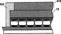
Fig. 1 showed before laminated product is combined into display; in the mode that releasing piece is peeled off from laminated product; sectional view through the basic frontal plane laminated product of the present invention. as shown in FIG. 1; this laminated product (be often referred to and be decided to be 10) comprises light-transmissive substrates 12; this substrate has the form of transparent plastic film; be 7 mils (177 microns) easily although the PET sheet. in Fig. 1, do not illustrate; substrate 12 can have one or more extra play; the basal surface of this substrate 12 (as shown in FIG. 1) forms the observation surface of final display, and these one or more extra plays are the protective seams that for example absorb UV radiation; prevent that oxygen or moisture from entering the restraining barrier of final display; be used to improve the anti-reflection coating of the optical property of final display.Substrate 12 is loaded with thin light transmission conductive layer 14, ITO preferably, and this thin light transmission conductive layer 14 is used as preceding electrode in final display.
Electro-optic medium layer (be often referred to and be decided to be 16) is deposited on the conductive layer 14, and electrically contacts with it.In the electro-optic medium shown in Fig. 1 is the electrophoretic media of the two particles encapsulation of anti-electric charge of type described in aforementioned 2002/0185378, and the electrophoretic media of the two particle encapsulation of this anti-electric charge comprises a plurality of microcapsules, each microcapsules comprises the capsule wall 18 that contains based on hydrocarbon liquid 20, is negative charge white particle 22 and the positive charge black particle 24 that suspends in hydrocarbon liquid 20.Microcapsules are maintained in the cementing agent 25.When on layer 16, applying electric field, white particle 22 is shifted to positive electrode, black particle 24 is shifted to negative electrode, like this for the observer who comes observation display by substrate 12, is just or negative according to any point layer 14 in final display with respect to base plate, makes layer 16 present white or black.
Fig. 2 shows the frontal plane laminated product (be often referred to be decided to be 10 ') of modification, it is except towards providing on the surface of the releasing layer 28 of electrophoretic media thin second conductive layer 30 (preferably aluminium), and it is consistent with the laminated product 10 shown in Fig. 1.Yet (on the surface of being provided at of can replacing of second conductive layer 30 away from the releasing layer of electrophoretic media., normally preferred in the layout shown in Fig. 2, this be because, as described below, second conductive layer 30 is used to test electrophoretic media, and on this medium, produce big as far as possible electric field for any given operating voltage, wish to keep the distance between two conductive layers as much as possible little .) as already noted, releasing piece 28 and conductive layer 30 can be formed by the PET film of calorize, although and this film is being obtainable on the market. in Fig. 2, do not illustrate, in some cases, character according to electro-optic medium, the coating that may need or wish to provide low-surface-energy material on second conductive layer 30 adheres to electro-optic medium such as silicon to prevent this layer.Although this lower-energy material has been introduced the additional electrical impedance to system, the impedance of most of electro-optic medium is very high, to such an extent as to the existence of additional impedance is not a problem.If necessary, can be adjusted in the used driving voltage of test period (as follows) so that allow additional impedance.
Fig. 2 show the laminated product 10 that is in the test ', conductive layer 14 ground connection and driving voltage V (be enough to cause that the optical states of electro-optic medium changes, and preferably equal the driving voltage that uses in final display) are applied to second conductive layer 30.Can realize by the zonule of releasing layer 28 is peeled off from adhesion layer 26 with contacting of second conductive layer 30, can obtain by similarly peeling off or from the zonule of laminated product, remove electro-optic medium or for example using crocodile clip to pierce through this medium with contacting of conductive layer 14.Advantageously, alternating voltage (preferably square wave) is applied to second conductive layer 30, so that whole laminated product 10 ' sheet flicker black or white. human eye even very responsive for the zonule that not have flicker in this zone, feasible even little defective is also observed easily.In addition, because this method of testing can easily be applied in large stretch of laminated product, in many cases little defective can be labeled out, and can regulate the process that subsequently sheet is cut into the required a plurality of parts of individual monitor, so just allow from sheet, to obtain the individual monitor of maximum quantity with some defective.
Under the low pressure situation of the driving voltage that the permission of the method for testing shown in Fig. 2 is used in corresponding to actual display, realize accurate the inspection, guaranteed so basically in the character of the shown laminated product of test period corresponding to the character that in final display, obtains.For example, (optical states changes more many slowly than needed by design rule) can easily be detected by this method in the zone of the electro-optic medium that the experience optical states changes. and this method for designing does not need high-voltage power supply, high-voltage power supply is harmful in some cases, so basically can residual electrostatic charge on this laminated product, so just be particularly suitable for automatic detection.
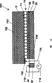
In Fig. 3, exemplarily show the preferred embodiment of the present invention's second method of testing, show second method of testing of the laminated product 10 that will be applied to shown in Fig. 1. as shown in FIG. 3, conductive layer 14 is with as the mode ground connection shown in Fig. 2. and electrostatic head 32 is to arrange near releasing layer 28, thereby distributes electrostatic charge on the exposed surface of releasing layer 28; Although shown in Figure 3 is positive charge, also can use negative charge and like this really, for the similar reason of having discussed, its favourable part is to apply the electric charge of negative polarity in the consecutive steps of test process.The electrostatic charge that is placed on the releasing layer 28 makes the optical states of laminated product 10 change.
Fig. 4 is the side height that the preferred embodiment (be often referred to and be decided to be 40) that (although being exemplary) be used for the method for testing of execution graph 3 is shown in more detail. and this device 40 comprises and is used for laminated product 10 is fixed on " transparent electrostatic chuck " (be often referred to and be decided to be 42) that is used on the position test. and (electrostatic chuck is better than the machinery folder, this is because electrostatic chuck guarantees that laminated product is definitely entirely supporting glass supporter, thereby in the image of seeing, eliminated the illusion of reflection .) chuck 42 comprises smooth glass plate 44, the optical adhesive of use is arranged and the plastic foil 46 (advantageously PET) of combination thereon, the surface of the exposure of this glass plate 44 is loaded with the spring nail 50 that ITO layer 48. is installed in the solenoid-activated on the chuck 42 and contacts with conductive layer 14 (see figure 1)s of laminated product 10, and between conductive layer 14 and 48, apply voltage, to produce electrostatic attraction between these layers, this electrostatic attraction is firmly held in laminated product 10 on the position of chuck 42 at test period.
Line scan camera 52 be installed in chuck 42 below, making that it passes through chuck can scanning slice stampings 10.The print head 54 of ion printing is installed on the chuck 42, with on the releasing layer 28 that electrostatic charge is applied to laminated product 10 according to mode shown in Figure 3 (Fig. 1). in U.S. Patent No. 4,160, the print head of describing the ion printing of type in 257 can obtain on market, a kind of experimental facilities has used the callable printhead from Xerox Docuprint 1300 electron beam printers, and this printer is to be sold by the Xerox Corporation company of the Stamford Connecticut of the U.S..Printhead 54 is provided the slide mechanism 56 (illustrating in highly exemplary mode) that is mounted with spring in Fig. 4, kept printhead 54 to be in constant distance place apart from the exposed surface of releasing layer 28 like this, typically about 0.5mm.Camera 52 and printhead 54 are attached (not shown) on shared linear movement platform, and their left sides from Fig. 4 of test period at laminated product 10 move to the right side, camera 52 is positioned in apart from the short distance of printhead 54 " downstream ", makes that the camera 52 scanned ranges of linearity are zones of passing through printhead 54 imagings recently.
Be the preference pattern of the device operation shown in Fig. 4 below. the operator is placed on laminate 10 on the electrostatic chuck 42.The operator uses the record mark (not shown) of fit bolt or printing to guarantee that sheet correctly aligns.When the interlocking lid (not shown) of operator's closed safe, nail 50 electrically contacts with conductive layer 14. and this device starts chuck 42 then, like this generation electric field and they are pulled in together between two conductive layers 14 and 48.
The print head 54 of ion printing becomes the saturated optical states of optics by driving electrophoretic media to releasing layer 28 injection ion beams. and this ion makes to form on conductive layer 14 and equates or opposite image charge, and final electric field has changed the color on the observation surface (the low surface among Fig. 4) of laminated product 10. along with the past of time, cross over electrophoretic media and be stored in energy in the electric field and lead by electricity and be dissipated.
Line scan camera 52 comes imaging layer stampings 10. these devices of design so that the laminated product by camera imaging is carried out accurately, shines uniformly by electrostatic chuck 42.The various parts of controller (not shown) opertaing device (camera, platform, light source etc.), and the image of handling camera 52 with the laminate determining to measure whether within manufacturing specification.Because need to detect the zone (promptly change the white portion of black inefficacy or change the black region that white lost efficacy) that in either direction, changes optical states and lost efficacy, at least need the scanning slice stampings for test completely 10 twice, the reversal of poles of printhead 54 between scanning. controller can use simple thresholding algorithm to determine the position of defective: for the optical states of each test, the pixel of the image of outside, reflectivity boundary line was considered to defective above and/or under those dropped on. and computing machine can be carried out more complicated processing to final picture element flaw data then, to determine whether laminated product has satisfied specification requirement.For example, the defect pixel of one group of vicinity may be referred to as individual defect.Computing machine can be counted other calculating parameters of the picture element flaw quantity on every area, the position of each defective, average defect area and any amount.
If equipment can indicate this sheet to be accepted or to refuse then. the unaccepted words of this sheet, this equipment can produce the numerical control program that is used for laser cutting machine, cuts into the littler sheet that satisfies specification with the laminated product sheet that will be under the test mode. perhaps abandon these unaccepted.
Should be noted that, compare with the situation of electro-optic medium, the voltage that needs to be applied to printhead 54 in this equipment is much smaller than think needed voltage according to the ignorant of the impedance of typical release layer, and as already noted, the print head voltage that needs in practice just in time is positioned within the limit of power of printhead of coml ion printing. for example, in an experimental program, used the equipment shown in Fig. 4, come the electrophoretic media of test package, in final display, this electrophoretic media switches it by the 15V driving pulse that use has 150 to 500 milliseconds of (msec) duration between the black and white state.In laminated product, the releasing layer of use is to have 10
13Ohm square centimeter (ohm cm
2) the PET film of impedance. only consider the impedance (about 10 of electrophoretic media
8Ohm square centimeter) with the impedance of releasing layer, people can reach a conclusion, and driving ink by releasing layer will need to surpass 100 ten thousand volts voltage.Yet the electric capacity of these layers is approximately identical, and (for electrophoretic media is 28pF/cm
2, and be 50pF/cm for releasing layer
2), therefore in practice, the pulse combined less than 1000V of crossing over electrophoretic media and releasing layer causes impedance-electric capacity spike of crossing over electrophoretic media, and they are loaded with enough energy and are used for the wherein conversion fully between the optical states.
In experiment, use the releasing layer and the Xerox printhead above-mentioned of electrophoretic media and 0.05mm (2 microns) as discussed above, use between driving pulse width, printhead and the releasing layer of drive electrode frequency, 30Hz of drive electrode voltage, the 50KHz of 1900VPP interval, successfully realized conversion fully between the black and white state with the tracking velocity of 10 mm/second as 0.5mm.Be its white optical state in order to drive medium, control electrode voltage is arranged on that 0V, screen electrode voltage are arranged on 180V and accelerating potential is arranged on+and 1000V. is its black optic state in order to drive medium, and control electrode voltage is set at that 200V, screen electrode voltage are arranged on 20V and accelerating potential is arranged on-and all voltages that provide of 1000V. are all with respect to common ground.
Fig. 5,6,7th, the photo of the physical device that in these experiments, uses.Fig. 5 illustrates whole testing device, and Fig. 6 illustrates the switching electro-optic medium and makes its printhead from white to black, and Fig. 7 illustrates the printhead control panel relevant with it that ion is printed.
This method of testing of the present invention has shown and has realized that optical states completely changes and provides breaking of capsule in the electro-optic medium that non-contact test method, this method of testing can not cause encapsulation and can obtain high test speed.
Fig. 8 illustrates a kind of laminated product (be often referred to and be decided to be 200), this laminated product assembles the laminated product shown in Fig. 1 10 closely, but be provided join domain with fenestra 202 shapes, this fenestra 202 extends through releasing piece 28, adhesion layer 26 and electro-optic medium layer 16, has exposed the zone of the conductive layer 14 at the place, bottom that is positioned at fenestra 202 like this.Fenestra 202 can form by the technology of any conventional, comprises for example degree of depth routing (depth routing) technology.Can form fenestra 202 with two stages (stage), phase one is removed releasing piece 28, and the phase one that subordinate phase is removed adhesion layer 26 and electro-optic medium layer 16. this process can be provided with degree of depth control by use and physically cut releasing piece 28 with the mechanical cutter of restriction depth of cut and finish.The bad part of releasing piece 28 can be removed by the absorption of for example vacuum plant. perhaps, can by laser ablation or dry etching particularly reactive ion etching (it is to carry out in the mode of high controllability and repeatability) releasing layer is removed.Etching can also be used to remove adhesion layer 26 and electro-optic medium layer 16, yet preferably uses the lithographic technique of conductive layer 14 as etching barrier layer., the optimization technique that is used to remove adhesion layer 26 and electro-optic medium layer 16 at present is wet method mechanical lapping; This technology can also be used to remove releasing piece 28. this mechanical lappings use non-wovens and non-pulverizing band (non-shredding tape) is effective especially such as the polyester regenerated fiber, and removes material by the effect of guillotine style.
Do not recommend to use the high energy material removal technology such as laser ablation to remove layer 26 and 16, this is because in fact this high energy technology tends to damage conductive layer 14.As already mentioned, from the PET film that covers ITO, form substrate 12 and conductive layer 14 easily, yet and such film can obtain on market., in this obtainable film, the thickness of ITO only is the magnitude of 100nm (0.1 micron), and therefore this ITO is damaged by high energy removal technology easily comparatively speaking.
In order to reduce infringement, advantageously increase the thickness of layer 14 in the location that will form fenestra 202 to conductive layer 14; Obviously, the thickness that increases whole conductive layer 14 is unpractiaca, and this is because when using display, and this layer and increases whole layer 14 thickness and will the optical property of display be had a negative impact between observer and electro-optic medium layer 16.Yet, fenestra 202 will typically be formed on the outer peripheral areas of display, normally sightless in use zone for example below the bezel (bezel) of display and be hidden, can increase the thickness of layer 14 like this and can the optical property of display not exerted an influence in this zone.The thickness of the conductive layer 14 that exposes by fenestra 202 the most at last in this zone can be realized by printed conductive ink on the ITO layer (such as silver or Graphite ink); What note is, conductive ink is before electro-optic medium layer 16 is applied to or is deposited on the conductive layer 14 and be printed on the relevant range of the PET/ITO film film of substrate 12 and conductive layer 14 (or similarly be used to form) in practice.
Form the generation that fenestra can cause a large amount of chips by some electro-optic medium.For example in Fig. 8, illustrate in the left side of fenestra 202 that microcapsules have lost " the blank zone territory, and this white space shows that (size of the microcapsules in Fig. 8 is too amplified certainly with respect to aperture window dimension owing to fenestra 202; In practice, the diameter that typical fenestra will have about 10 microcapsules magnitudes) formation, microcapsules that caused feasible layer 16 to disappear. microcapsules that should " losing " are pulverized during the formation of fenestra 202, therefore form chip in fenestra.These chips must be removed before the frontal plane laminated product is used in the display, and this is to disturb because it can electrically contact to produce to the necessity between conductive layer 14 and the display base plate.Some method that is used to form fenestra 202 for example wet method mechanical lapping itself can be used for chip is effectively removed from electro-optic medium, if but the method itself that is used to form fenestra 202 can not be removed chip, then can use for example plasma etching or use liquid or gas stream flushing fenestra removes chip of arbitrarily known chip removals technology, to such an extent as to can not produce the negative effect that infringement can not receive the optical property generation of final display as long as employed chip is removed technology certainly to electro-optic medium.
In final display, fenestra 202 is filled with conductive material, thereby forms conductive path between the base plate of preceding electrode (conductive layer 14) and display.Although (fenestra 202 only is shown in Fig. 8, but in fact can advantageously provide more than one fenestra at the partial interior of the frontal plane laminated product 10 that is used to form individual monitor, between the base plate of display and preceding electrode, a plurality of conductive paths are provided like this, even like this for example owing to form under the situation of the conductive path disabler that fragmentation caused of material of conductive path, still allow display correctly to work.Yet) before being laminated to the frontal plane laminated product on the base plate or be simultaneously basically, it is effective using conductive material to fill fenestra 202.
Fig. 9 illustrates frontal plane laminated product (be often referred to and be decided to be 210), wherein filling fenestra 202. before the lamination in Fig. 9, fenestra 202 shown in Fig. 8 has been filled with conductive material to form conductive through hole 204, and this through hole is the exposed surface that extends to releasing piece 28 from conductive layer 14.Through hole 204 can form by any conductive material, although the material that uses deformable conductive material for example to comprise conductive particle in the polymeric matrix is easily.Such conductive material comprises silver-colored ink, fills epoxy resin, the silicon that contains metal and the other materials of silver. interchangeable scheme is that through hole 204 can be formed by conductive strips.Can be in mode easily arbitrarily, for example by ink being printed onto the frontal plane laminated product or the mode that conductive material is expelled in the fenestra 202 being inserted into conductive material in the fenestra 202 by pin.Should be noted that, it is not unacceptable using such process such as printing process (may stay unnecessary conductive material on the surface of releasing piece 28), this is because before being laminated to the frontal plane laminated product on the base plate, and unnecessary conductive material and releasing piece 28 are removed.If this conductive material is the type that needs curing, then after conductive material is inserted into fenestra 202, partly solidified conductive material is effective, but expectation is the final curing of conductive material to be postponed be cured after being laminated to the frontal plane laminated product on the base plate again, so that conductive material can keep being out of shape slightly during lamination, thereby better electrically contacting of feasible and base plate. the advantage of using the epoxy resin of filling silver to form conductive through hole 204 is that this material does not need the residence time for curing before lamination; As described below, the laminated product that conducts electricity in the preferred temperature range that raises makes the silver filling during lamination epoxy resin cure.
Typically form the frontal plane laminate structures shown in Fig. 8 and 9, and the frontal plane laminated product still is the form of body piece or grid. next, the frontal plane laminated product will typically be cut into a plurality of that form the individual monitor required size.It is effective using laser cutting machine or cutting clamp to carry out this cutting. a significant advantage of the present invention is, can prepare the frontal plane laminated product with the form of grid, the sheet that is cut to multiple different size then is to be used for different displays; The manufacturer of frontal plane laminated product does not need to preserve the sheet of the different size of huge stocks like this, and can prepare the frontal plane laminated product of grid configuration, and this grid is cut into the sheet of different size according to received order. in addition, it should be noted that, the electro-optic medium of cutting some type may cause the formation of chip, for example, therefore after cutting, may need suitable cleaning so that remove these chips from the chip of ruptured capsules of the electrophoretic media of encapsulation.
The present invention carries out in the various steps of preparation frontal plane laminated product in order, and pliability is provided.For example, this grid can at first be cut off and remove each layer that acts on the single laminated product sheet, rather than remove (perhaps randomly inserting conductive material) in the grid part with releasing piece, adhesion layer and electro-optic medium the past plane layer stampings. in this case, that may expect provides anchor clamps or clamp keeping the sheet of laminated product, removes releasing layer, adhesion layer and electro-optic medium so that guarantee effectively from the zone of the explication of laminated product sheet. and it is possible that other in the process steps change in proper order that yes; For example when the laminated product of preparation among Fig. 9, on the grid of laminated product, form fenestra 202 (Fig. 8) and may be effectively (this laminated product is cut off subsequently to produce single sheet), and (may just before the laminated product sheet is in turn laminated on the base plate) inserts conductive material to form conductive through hole after cutting off.
, before being integrated into following display with reference to Figure 10 to 17, the frontal plane laminated product shown in Fig. 8 and 9 need be tested the frontal plane laminated product by aforesaid any means.
Ensuing key step in forming the Electro-Optical Display process is that the frontal plane laminated product is laminated on the base plate. before being laminated to the frontal plane laminated product shown in Fig. 8 and 9 on the base plate, must remove releasing piece 28.By on the exposed surface that adherent zone is applied to releasing piece and use adherent zone that releasing piece is peeled off from adhesion layer, can effectively carry out the step that this is removed. perhaps, in some cases, can arrange releasing piece with the edge that extends beyond adhesion layer 26 and electro-optic medium layer 16 (for example using the releasing piece grid wideer than the adhesion layer that applies 26), " projection " that stay one or more releasing piece of can hand grabbing and drawing is (tab) to remove releasing piece. remove releasing piece 28 to expose the adhesion layer 26 that preparation is used for lamination process.
Exemplary illustrating is laminated to base plate 406 with the frontal plane laminated product 210 shown in Fig. 9 among Figure 10; this base plate 406 is provided with pixel electrode 408 and contact pad 410. Figure 10 and is illustrated in when the frontal plane laminated product is laminated to base plate 406, protective seam 412 is laminated on the substrate 12 of frontal plane laminated product 10.Although need provide such protective seam for the reason of discussing below; but protective seam does not need to be attached to and is used for the frontal plane laminated product is laminated to same laminated product used on the base plate; and typically after the frontal plane laminated product has been in turn laminated on the base plate, protective seam will be applied in the second layer stampings.Perhaps before electro-optic medium 16 was applied to substrate, protective seam 412 can be applied to substrate 12.Should be noted in the discussion above that with respect to position shown in Figure 9, the frontal plane laminated product is reverse in Figure 10.
Figure 10 is illustrated in removable warm table 416 and the roller 414 that use is moved along the arrow A direction in the lamination process and carries out lamination.Base plate 406 is placed on the platform 416, the cutting blade of frontal plane laminated product 210 is placed on the base plate 406, use pre-aligned aligning reference marker for example the edge with reference to frontal plane laminated product 210 and base plate 406 are preferentially aimed at, so that control is parallel to the aligning in the both direction on plane of platform 416, thereby before lamination, realize the accurate aligning of two parts.Protective seam 412 can be placed on the frontal plane laminated product 210 then.
When on time; by on roller 414 times along advance platform 416 and protective seam 412, frontal plane laminated product 210, base plate 406 is laminated together of arrow A direction; and the stacking material on the platform 416 remains under the temperature of specific rising; it is desirable to scope at 50-150 ℃; and for hot melt adhesive such as vinyl acetate ethylene preferably 80-110 ℃ scope. roller 414 can be heated or not heat, and expectation is exerted pressure scope 0.2 to 0.5Mpa and preferably at 0.35 to 0.5Mpa pressure.Lamination adhesion layer preferably temperature activates or pressure activation, so that these heat and pressure have so just formed Electro-Optical Display with frontal plane laminated product 210 and base plate 406 bottoms of passing through roller 414 as lamination laminated together.As can be seen from Fig. 10 be, arrange that laminated product makes conductive through hole 204 contact with contact pad 410, the while electro-optic medium be arranged in pixel electrode 408 near; What need certainly is that contact pad 410 is isolated with pixel electrode 408 electricity, so that the electromotive force that is applied on public preceding electrode (conductive layer by the frontal plane laminated product forms) and the pixel electrode can independently change, be enough to change the wherein electric field of the leap electro-optic medium of optical states with generation.
Can change the laminated product process with several different methods. for example, it is static that platform 416 can keep, roller 414 moves. and roller 414 and platform 416 can not heat, if and the adhesive of laminated product can be activated by roller 414 applied pressures. use frontal plane laminated product rather than the frontal plane laminated product among Fig. 9 among Fig. 8 to make laminated product conduct electricity, the epoxy resin that then deformable conductive material is for example filled silver can be printed on or be deposited on the contact pad 410, make that this deformable conductive material is injected into (Fig. 8) in the fenestra 202 during lamination, conduct the hole thereby during lamination process, form.Can also use two rollers (heating or not heating) rather than roller and Tai Lai to carry out lamination.
Can also carry out the multiple basic modification of lamination process.Lamination process shown in Figure 10 is " sheet-sheet " process, and wherein the single section of frontal plane laminated product is in turn laminated on the single base plate.Yet, can carry out lamination process with roller-roller pattern, the grid of frontal plane laminated product is in turn laminated on the grid that comprises a plurality of base plates (being formed on the soft substrate); Such grid may use the transistor that is formed by polymer semiconductor, as described in the patent of aforesaid some E Ink and MIT and open application.This roller-roller lamination can be by carrying out these two grids through the clip between the pair roller, this pair roller can be heating or without heating, this depends on the type of employed adhesive.For the technician in conductive roller-roller process field, it is evident that in such roller-roller lamination, releasing piece removed the take-up roller of can be by stress application releasing piece being separated in the plane layer stampings in the past in the plane layer stampings in the past and " online " carry out, and the separated releasing piece on the frontal plane laminated product twines.Such roller-roller lamination process can also be adjusted well to be used for lamination protective seam simultaneously.After roller-roller lamination process, certainly " display " grid of cutting combination is to produce single display.
Can also carry out lamination with the pattern that is referred to as " grid-sheet " on the term, make the continuous grids (being stripped from releasing piece) of frontal plane laminated product be laminated on a plurality of base plates that are arranged on the suitable holder, the grid that cuts this frontal plane laminated product then is to produce single display.
Must be careful when the environmental baseline of selection such as relative humidity and temperature, frontal plane laminated product/backplane level stampings are affected under such environmental baseline, this is because shown these conditions, at least under the situation of electrophoretic media display of encapsulation, influence the optical property of the display that laminated product produces.For such electrophoretic display device (EPD), laminated product should be under the relative humidity of 20 to 60 number percents effectively, and best is effective under the relative humidity of 40 number percents.In addition, for such electrophoretic display device (EPD), preferably, about room temperature for example 15-25 ℃ temperature range carry out lamination process. except relative humidity and temperature, need other environmental parameter of control.Lamination process expectation be to carry out having under the clean room environmental situation of low granule number, to improve output. this environment also should not have static. when being removed in releasing piece the past plane layer stampings, because the Electrostatic Discharge that a large amount of generations of static cause may damage base plate. in order to reduce ESD, the lining of current plane layer stampings is stamped releasing piece and after removing releasing piece, and the frontal plane laminated product is placed on the laminating bench or in roller-roller process during by lamination, can use ion big gun or rifle with electroneutral Ionized particle jetting on the frontal plane laminated product.This Ionized particle be used to the discharge or with the charge neutrality of frontal plane laminated product. in addition, the environment of laminated product should be comprised ground connection such as operator, base plates by suitable ground connection, so that further reduce the danger of ESD.
As can be seen from Fig. 10, after lamination, even applied diaphragm, but the edge of electro-optic medium is exposed to environment at least, and as mentioning in front, many electro-optic medium are subjected to Effect of Environmental such as humidity, oxygen and particulate easily.Therefore,, can seal the negative effect of display, increase the mission life of display like this to prevent that these environmental factors from causing electro-optic medium according to the present invention.The example of these useful sealings has been shown in Figure 11-17.
Figure 11 shows " chamfering " edge sealing 520.(for brevity, in Figure 11 to 17, having omitted pixel electrode).In such sealing; substrate 12 and protective seam 412 are sizes (be parallel to the plane surveying of base plate 406) identical with the electro-optic medium layer and to seal 520 be leg-of-mutton cross section basically; has a kind of lateral thickness (being parallel to the plane surveying of base plate 406); this thickness is that to be reduced to protective seam 412. sealing 520 from base plate 406 be that surface from base plate 406 extends upward; but do not pass through protective seam 412, as shown in figure 11.
The sealing 520 and shown in Figure 12 to 17 other the sealing, can the periphery of suitable seal material distribution in electro-optic medium be formed by the standard distributing equipment that use is used to prepare.For example can use conventional robot pin divider (robotic needle dispenser) to distribute sealing 520 with 0.3 to 0.6 millimeter thickness and 0.8 to 1.5 millimeter width.Perhaps, printing process such as the serigraphy, printing, decoration firing (transfer) that can use standard etc. is being printed on encapsulant on frontal plane laminated product 10 or the base plate 406 before the lamination.
The angle that chamfering sealing 520 shown in Figure 11 is handled and made from display has superiority; this is because it is easily mutually integrated with other steps that are used to make display. claimed layer 412 of the geometric configuration of other edges sealings shown in Figure 12 to 17 (in some cases; also have substrate 12) have a size different with the size of electro-optic medium layer; and such size difference may need additionally to handle and/or making step, makes the complex manufacturing process of whole display like this.
Figure 12 shows " overlapping " sealing 522. in such sealing; protective seam 412 extends beyond the periphery of electro-optic medium layer segment less than electro-optic medium layer (being parallel to the plane surveying of base plate 406) and encapsulant; and contacting with the periphery of protective seam 412. sealing 522 extends upward from base plate 406; but do not pass through protective seam 412, as shown in Figure 12.
Figure 13 shows " underfill " sealing 524.In the sealing of such type; protective seam 412 extends between the periphery of base plate 406 and protective seam 412 greater than electro-optic medium layer (being parallel to the plane surveying of base plate 406) and encapsulant, and the periphery of this protective seam 412 extends beyond the periphery of substrate 12 and electro-optic medium.
" real underfill " shown in Figure 14 sealing 526.In such sealing, protective seam 412, substrate 12 and (optional) conductive layer 14 be all greater than electro-optic medium layer (being parallel to the plane surveying of base plate 406), expectation be to have about 0.5 to 1.5 mm distance.Before frontal plane laminated product 10 or 210 is laminated to base plate 406; by can provide near remove the electro-optic medium layer periphery of display periphery must " suspension " protective seam 412, substrate 12 and conductive layer 14. in addition; before this lamination; encapsulant is dispensed near the periphery of display; make to be laminated on a time-out when base plate 406 and frontal plane laminated product 10, form edge sealing 526.Perhaps, by use capillary force or directly extruding sealant be filled into carry out near the electro-optic medium the areola can applying encapsulant after the lamination.
Underfill in Figure 13 and 14 seals its superiority and is, before environmental factor can affact electro-optic medium 16, only allows environmental factor to spread (in Figure 13 and 14 from left to right) in the one dimension direction and through the basic thickness of encapsulant.Screening glass tends to the environmental factor diffusion influence that is not vulnerable to wherein pass with respect to encapsulant; therefore the sealing that is to use underfill of expectation; the sealing of this underfill guarantees that these environmental factors must spread and the basic thickness of process encapsulant in arrival with before influencing electro-optic medium in the one dimension direction, this contrasts with these factors of permission are moved to electro-optic medium in two-dimensional directional seal type formation.
Figure 15 illustrates " noncontact is overlapping " sealing 550.The very similar lap seal shown in Figure 12 522 of such sealing, but the sealing material does not extend to the edge of diaphragm 412, stays the slit between encapsulant and diaphragm.What expect is as shown in figure 15, and soft sealant 522 is inserted in the slit to improve the sealing of electro-optic medium 16.Rule of thumb have been found that; in the lap seal 522 of Figure 12; for the possibility of encapsulant existence from the edge effusion of diaphragm; this is because the difference between the various material coefficient of thermal expansion coefficients that use in display; and the difference degree at the layer at the different distance place of distance base plate is the restriction of laterally moving that is subjected to respect to base plate. the fracture that forms between the neighbouring surface of encapsulant and diaphragm; sealing for electro-optic medium has negative effect; therefore and having a negative impact for the mission life of display. noncontact lap seal 550 allows relatively moving slightly between encapsulants and the diaphragm, and can the sealing of electro-optic medium not had a negative impact.
Figure 16 illustrates " dam of underfill " sealing 560.Yet such sealing is very similar to the real underfill sealing 526. shown in Figure 14, and in underfill dam sealing 560, the end of photonic layer and conductive layer lacks the edge of substrate 12, makes the periphery of substrate 12 expose like this.In addition; underfill dam sealing 560 comprises that protection 562. dams 562, dam form from curable material; epoxy resin for example; this curable material is distributed in arbitrary end of base plate 406 or on the frontal plane laminated product; and before base plate and frontal plane laminated product is laminated together, this curable material is cured, dam 562 is positioned it is extended between the exposed periphery part of base plate 406 and above-mentioned substrate 12.
Figure 17 shows " raceway groove " sealing 570.Such sealing is very similar to underfill dam sealing 560 shown in Figure 16, but two the isolated globules 572 and 574 that distribute have been to use, these globules are carrying out base plate and frontal plane laminated product to be cured before the lamination, to define two raceway grooves between the globule. fill this raceway groove with encapsulant then, but carried out this step before lamination step.
In the sealing shown in Figure 16 and 17, can between base plate and frontal plane laminated product, introduce globule at interval, to prevent outstanding (promptly the extruding) of encapsulant in lamination step.
In some cases, advantageously before using encapsulant, adhesion promoter (adhesion promoter) is applied on frontal plane laminated product and/or the base plate, to realize the improved adhesiveness of encapsulant base plate and frontal plane laminated product.
If independent edge sealing can not provide enough protection with the opposing Effect of Environmental, then should apply barrier strip.Such barrier strip is preferably along the peripheral disposition of frontal plane laminated product 10, to realize the barrier properties of edge sealing 510.This barrier strip can be the die-cut small pieces of the adhesion of polychlorotrifluoroethylene (by Honeywell International, selling registered trademark MarkAclar on the Inc market), metallized PET, aluminium or stainless steel support.Similarly be can apply additional barrier film to diaphragm and make it avoid such environmental effects to the protection of display with further enhancing. similarly be on diaphragm 412, to apply the environmental integrity of additional barrier film with further enhancing display.
Figure 18 illustrates by being similar to another frontal plane laminated product of the present invention (be often referred to and be decided to be 600) of method test shown in Figure 2.Frontal plane laminated product 600 comprises releasing piece 28, adhesion layer 26, electro-optic medium layer 16, conductive layer 14 and the substrate 12 that provides conductive layer 30, yet they basically all with the frontal plane laminated product 10 shown in Fig. 2 ' counterpart identical., frontal plane laminated product 600 also comprises the aid adhesion layer 702 that is positioned at apart from the apparent surface of the substrate 12 of conductive layer 14, this aid adhesion layer 702 is to be formed by transparent adhesive, and auxiliary releasing piece 704 is positioned on the opposite flank apart from the adhesion layer 702 of substrate 12.Frontal plane laminated product 600 also comprises the contact pad 706 on the periphery that is positioned at conductive layer 14 that is formed by silver-colored ink.Releasing piece 28 by contiguous contact pad 706 forms fenestra 708, and removes part electro-optic medium layer 16 and the adhesion layer 26 that covers on the contact pad 706, makes contact pad 706 can contact by the exposed surface of fenestra 708 from releasing piece 28.
Figure 18 illustrate use with Fig. 2 in used essentially identical process test frontal plane laminated product 600. as can be seen from Fig. 18 be, the periphery 28 of releasing piece ' extend beyond substrate 12, stay like this zone 30 of the conductive layer 30 of exposure '.Electric conductor 710 is with zone 30 ' contact with voltage source 712, and this voltage source also contacts with second conductor 714.Conductor 714 passes fenestra 708 and contacts with contact pad 706, makes voltage source 712 that voltage is applied between conductive layer 14 and 30 like this, and changes the optical states of electro-optic medium layer 16.
Frontal plane laminated product 600 can be at first made by aid adhesion layer 702 and auxiliary releasing piece 704 are applied on the substrate 12 that is provided with conductive layer 14; As described in front, advantageously, substrate 12 and conductive layer 14 are that the film by obtainable PET/ITO or similar components on the market constitutes.Contact pad 706 is printed on the surface of exposure of conductive layer 14 then.Next, conductive layer 14 (comprise and be touched 706 zones that occupy) is coated with electro-optic medium, follows by adhesion layer 26, and the releasing piece 28 that this adhesion layer 26 is provided with conductive layer 30 successively covers.Finally, fenestra 708 is by releasing piece 28 and adhesion layer 26 and adopts the above-mentioned electro-optic medium of removing from contact pad 706 with reference to figure 2 described any-modes 16 to form.Frontal plane laminated product 600 has been ready for the test shown in Figure 18 now.
The frontal plane laminated product 600 that Figure 19 illustrates Figure 18 is laminated on the base plate 406 that is provided with pixel electrode 408 and conductive welding disk 410, they all with the appropriate section basically identical of the base plate shown in Figure 10.Set up electrically contacting between the contact pad 410 of frontal plane laminated product 600 and base plate 406 by the conductor 720 that forms of conduction adhesive; Yes and pixel electrode 408 electricity are isolated for this contact pad 410. in order to make the structure shown in Figure 19, the conduction adhesive can be printed on the contact pad 410, remove releasing piece 28 in the plane layer stampings 600 in the past, and use aforesaid any technology that base plate and frontal plane laminated product is laminated together.
Figure 20 illustrates a kind of display (be often referred to and be decided to be 800) of form; this display can prepare from the laminar structure shown in Figure 19. in order to make display 800; auxiliary releasing piece 704 is removed from the aid adhesion layer; frontal plane laminated product/base arrangement is (in order to illustrate conveniently then; in Figure 20, omitted contact pad 410 and pixel electrode 408) be in turn laminated to barrier film 802; this barrier film 802 is greater than (plane that is parallel to base plate 406) frontal plane laminated product 600. another diaphragms 802; the PET film that preferably has about 200 micron thickness; this diaphragm 802 is provided with the adhesion layer of the lamination that is formed by transparent adhesive, is in turn laminated to then on the surface of exposure of diaphragm 802.Next; encapsulant 808 is injected in the slit between base plate 406 and the barrier film 802; thereby, formed the sealing of the underfill type that is similar to the sealing 524 shown in Figure 13 on the principle except encapsulant 808 is to extend to barrier film 802 rather than extend to the diaphragm 412 from base plate 406.
Although do not have shown in the drawings, base plate 406 is provided with circuit, this circuit links to each other with contact pad 410 (Figure 19) pixel electrode 408 with the periphery of base plate, base plate 406 is attached with provides the band of driver IC 812 (work of control display) to connect packaging body 810; Band connects packaging body 810 and is connected to printed circuit board (PCB) 814.
Used the frontal plane laminated product with at least one fenestra with reference to figs. 2 to the 20 concrete displays of describing above, this fenestra is formed by releasing layer, adhesion layer and electro-optic medium layer, makes this fenestra be surrounded by these layers fully.Yet it is not main using these fenestras.Releasing layer, adhesion layer and electro-optic medium layer can be removed from the location of the periphery of contiguous frontal plane laminated product, make " fenestra " have the shape of depression in the edge of releasing layer, adhesion layer and electro-optic medium layer.Perhaps, the exposed region of the conductive layer that need electrically contact with base plate of frontal plane laminated product does not provide by removing releasing layer, adhesion layer and electro-optic medium layer, but by not using these extra plays to come the specific region of coated with conductive layer to form, as shown in Figure 21 and 22.
Figure 21 illustrates " road " coating procedure, wherein deposits the continuous bar 920 of electro-optic medium on grid 922, and this grid 922 can form the substrate of frontal plane laminated product.A plurality of zones of conductive material (only showing two zones in Fig. 9) are provided on the grid 922, each city, district in these zones has the shape of rectangle 924 (it is covered fully by the bar 920 of electro-optic medium), the edge that has exceeded bar 920 from the projection 926 of rectangle 924 extensions, although make the part of projection 926 do not covered by electro-optic medium. in Figure 21, do not illustrate, the adhesion layer of frontal plane laminated product applies with identical pattern as electro-optic medium subsequently, make in the final grid of frontal plane laminated product, part projection 926 does not contain electro-optic medium and adhesion layer, thereby there is no need before being laminated to the frontal plane laminated product on the base plate these two layers to be removed from the partially conductive layer.
The projection 926 of the exposure of conductive material can be laminated directly on the suitable contact pad on the base plate.Yet, usually preferably, before lamination, with deformable conductive material such as those previously mentioned coated materials on base plate, make these deformable conductive materials between contact pad on the base plate and projection 926, to guarantee the excellent electric contact between contact pad and the clip.
Should be understood that the form of conductive layer may have a large amount of modification in process shown in Figure 21.For example, conductive layer can have the form of continuous striped, the projection that provides with predetermined distance along one or two edges of striped is provided this continuous striped, make these stripeds can be cut off so that the sheet of the frontal plane laminated product that is suitable for individual monitor to be provided, and each display have at least one projection.Perhaps, conductive layer can be for the form of the simple shape of projection, and the form with striped applies electro-optic medium, this striped is narrower than the striped of conductive material, stayed one or more edge of the conductive material that exposes like this, the join domain that contacts with base plate so that current plane layer stampings to be provided by lamination.
Figure 22 illustrates the process that is similar to Figure 21, but wherein electro-optic medium applies as a series of sticking patch 930 rather than as continuous striped, each sticking patch 930 is used for a display. and can use the process of the modification of Figure 22, the frontal plane laminated product that is fit to use the real underfill sealing among Figure 14 is provided.If revise the whole surface of conductive layer with the grid 922 of extend through backing material, and electro-optic medium is applied by the sticking patch 930 of appropriate size, cut off grid 922 between the adjacent sticking patch sheet of frontal plane laminated product is provided, wherein substrate and conductive layer extend beyond all peripheries around the electro-optic medium layer of electro-optic medium, as it is needed to be used to form the real underfill sealing of Figure 14.
Choose wantonly, in process of the present invention, after being laminated to the frontal plane laminated product on the base plate and before or after sealing forms (although the latter is typical preferred), can be in autoclave the making layer laminated structure, be about to it and put into autoclave, this autoclave is the chamber that environment is controlled, and the temperature and pressure that wherein can raise is to toast this structure.Such autoclave helps forcing those little air voids in laminate structures to be removed by heating.Perhaps, removing of space can be realized by under vacuum condition the frontal plane laminated product being laminated on the base plate.
Process of the present invention is compared with the traditional monitor manufacturing technology by reducing step number and needed material, can simplify the making of Electro-Optical Display and the output of increase display manufacturing process greatly, so just reduce the cost of making this display significantly.
Those skilled in the art should be understood that, can carry out change on various forms and the details to above-described specific embodiments of the invention.For example, can replace with vacuum chuck at the electrostatic chuck shown in Fig. 4 42, although vacuum chuck has such shortcoming: vacuum chuck has the shortcoming of visual vacuum hole, make that the defective that detects near the hole is very difficult, and may test each laminated product sheet twice in the diverse location place on chuck subsequently, so that detect the defective of covering owing to vacuum hole a position.Similarly be that line scan camera 52 can be replaced by the optical devices of matrix camera and focusing.
Claims (24)
1. frontal plane laminated product that is used for Electro-Optical Display comprises successively:
The conductive layer of printing opacity;
The solid-state electro-optic medium layer that electrically contacts with conductive layer;
Adhesion layer; And
Releasing piece.
2. frontal plane laminated product according to claim 1 is characterized in that conductive layer comprises metal oxide.
3. frontal plane laminated product according to claim 2 is characterized in that conductive layer comprises indium tin oxide.
4. each described frontal plane laminated product in requiring according to aforesaid right is characterized in that electro-optic medium comprises dichromatic parts medium of rotation or electric look medium.
5. frontal plane laminated product according to claim 1 is characterized in that electro-optic medium is an electrophoretic media.
6. frontal plane laminated product according to claim 5 is characterized in that, electrophoretic media is the electrophoretic media of encapsulation.
7. frontal plane laminated product according to claim 1 is characterized in that join domain, and this join domain constitutes the part of the periphery of conductive layer, and conductive layer exposes in this join domain, does not have electro-optic medium and adhesion layer.
8. frontal plane laminated product according to claim 7 is characterized in that, join domain is to be formed by the fenestra that extends through electro-optic medium and adhesion layer, makes this join domain be surrounded by electro-optic medium and adhesion layer.
9. frontal plane laminated product according to claim 7 is characterized in that releasing piece does not extend across join domain.
10. frontal plane laminated product according to claim 7 is characterized in that, the contact pad of conductive material covers on the conductive layer in the join domain, and contact pad and conductive layer and conductive through hole electrically contact, and form conductive through hole on join domain.
11. frontal plane laminated product according to claim 1 is characterized in that conductive through hole and conductive layer electrically contact, and extends through therefrom or process electro-optic medium layer and adhesion layer.
12. frontal plane laminated product according to claim 11 is characterized in that, is not released sheet away from the end of the conductive through hole of conductive layer and covers.
13. frontal plane laminated product according to claim 11 is characterized in that, conductive through hole is to be formed by deformable material.
14. frontal plane laminated product according to claim 13 is characterized in that, conductive through hole is by comprising that the material that is dispersed in the conductive particle in the polymeric matrix forms.
15. frontal plane laminated product according to claim 11 is characterized in that, the contact pad of conductive material is inserted between conductive layer and the conductive through hole, and contact pad and conductive layer and conductive through hole electrically contact.
16. frontal plane laminated product according to claim 1 is characterized in that second conductive layer is arranged on the releasing piece.
17. frontal plane laminated product according to claim 1 is characterized in that, the aid adhesion layer is on the apparent surface away from the conductive layer of electro-optic medium.
18., it is characterized in that auxiliary releasing piece covers the aid adhesion layer according to the described frontal plane laminated product of claim 17.
19. a frontal plane laminated product that is used for Electro-Optical Display comprises successively:
The conductive layer of printing opacity;
The solid-state electro-optic medium layer that electrically contacts with conductive layer; With
Adhesion layer,
These article are characterised in that join domain, and conductive layer exposes in this join domain, do not have electro-optic medium and adhesion layer.
20. a frontal plane laminated product that is used for Electro-Optical Display comprises successively:
The conductive layer of printing opacity;
The solid-state electro-optic medium layer that electrically contacts with conductive layer;
Adhesion layer,
These article are characterised in that the conductive through hole that electrically contacts with conductive layer, and extend through therefrom or process electro-optic medium layer and adhesion layer.
21. an Electro-Optical Display comprises successively:
The conductive layer of printing opacity;
The solid-state electro-optic medium layer that electrically contacts with conductive layer;
Adhesion layer and
Base plate with at least one pixel electrode, the feasible electromotive force that is applied between conductive layer and the pixel electrode can change the optical states of electro-optic medium, at least one contact pad that this base plate also comprises and at least one pixel electrode electricity is isolated,
This display is characterised in that, thereby at least one conductive through hole extends through or arrives contact pad or a plurality of contact pad one through electro-optic medium and adhesion layer from conductive layer.
22. a method that is used to make solid-state Electro-Optical Display, its process comprises:
A kind of frontal plane laminated product that is used for Electro-Optical Display of making is provided, and it comprises successively:
The conductive layer of printing opacity;
The solid-state electro-optic medium layer that electrically contacts with conductive layer;
Adhesion layer; With
Releasing piece;
Provide and comprise a plurality of pixel electrodes and arrange the base plate that applies the drive unit of variable potential to this pixel electrode;
From adhesion layer, remove releasing piece; With
Making adhesion layer adhere under the condition on the base plate, adhesion layer is contacted with base plate, thereby adhesion layer, electro-optic medium layer and conductive layer are fixed on the base plate.
23. a method that is used to form Electro-Optical Display, its process comprises:
A kind of front assembly is provided, and this front assembly comprises successively: the conductive layer of printing opacity; The solid-state electro-optic medium layer that electrically contacts with conductive layer; Adhesion layer;
Electro-optic medium and adhesion layer are removed from the part front assembly, thereby a kind of join domain are provided,
Expose at this join domain conductive layer, do not have electro-optic medium and adhesion layer;
On join domain, form conductive through hole;
A kind of base plate is provided, it comprise at least one pixel electrode and at least one contact pad of isolating with this at least one pixel electrode electricity and
Front assembly is laminated to base plate, make adhesion layer adhere to base plate, electro-optic medium be disposed at least one pixel electrode near, and conductive through hole and at least one contact pad electrically contact, thus conductive layer is electrically connected with at least one contact pad by conductive through hole.
24. a method that is used to form Electro-Optical Display, its process comprises:
A kind of substrate that comprises the conductive layer of printing opacity is provided;
On the part substrate, apply solid-state electro-optic medium, stay the join domain of uncoated substrate;
On electro-optic medium, apply adhesion layer, stay uncoated join domain, thereby form front assembly;
A kind of base plate is provided, and it comprises at least one pixel electrode and the contact pad of isolating with this at least one pixel electrode electricity; With
Front assembly is laminated to base plate, makes adhesion layer adhere to base plate, electro-optic medium be disposed at least one pixel electrode near, and the conductive layer in the join domain and contact pad electrically contact.
Applications Claiming Priority (4)
| Application Number | Priority Date | Filing Date | Title |
|---|---|---|---|
| US31930002P | 2002-06-10 | 2002-06-10 | |
| US60/319,300 | 2002-06-10 | ||
| US32018603P | 2003-05-12 | 2003-05-12 | |
| US60/320,186 | 2003-05-12 |
Related Child Applications (1)
| Application Number | Title | Priority Date | Filing Date |
|---|---|---|---|
| CN2009101332766A Division CN101520587B (en) | 2002-06-10 | 2003-05-23 | Component and method for electro-optic display |
Publications (2)
| Publication Number | Publication Date |
|---|---|
| CN1659473A CN1659473A (en) | 2005-08-24 |
| CN100489637C true CN100489637C (en) | 2009-05-20 |
Family
ID=29739317
Family Applications (2)
| Application Number | Title | Priority Date | Filing Date |
|---|---|---|---|
| CNB038134543A Expired - Lifetime CN100489637C (en) | 2002-06-10 | 2003-05-23 | Components and methods for use in electro-optic displays |
| CN2009101332766A Expired - Lifetime CN101520587B (en) | 2002-06-10 | 2003-05-23 | Component and method for electro-optic display |
Family Applications After (1)
| Application Number | Title | Priority Date | Filing Date |
|---|---|---|---|
| CN2009101332766A Expired - Lifetime CN101520587B (en) | 2002-06-10 | 2003-05-23 | Component and method for electro-optic display |
Country Status (8)
| Country | Link |
|---|---|
| US (14) | US6982178B2 (en) |
| EP (3) | EP2916168B1 (en) |
| JP (10) | JP4986397B2 (en) |
| KR (10) | KR100937612B1 (en) |
| CN (2) | CN100489637C (en) |
| AU (1) | AU2003256260A1 (en) |
| HK (2) | HK1079294A1 (en) |
| WO (1) | WO2003104884A2 (en) |
Cited By (4)
| Publication number | Priority date | Publication date | Assignee | Title |
|---|---|---|---|---|
| CN103913920A (en) * | 2013-01-09 | 2014-07-09 | 元太科技工业股份有限公司 | Electrophoretic display device |
| CN106660354A (en) * | 2014-05-08 | 2017-05-10 | 哥兹有限公司 | Device for producing and testing electrical switchable glasses and method of doing the same |
| CN109656077A (en) * | 2019-01-24 | 2019-04-19 | 中山大学 | Stretchable color electric paper and the stretchable color electric paper of self-powered |
| CN109983399A (en) * | 2016-11-30 | 2019-07-05 | 伊英克公司 | It is laminated electro-optic displays and its manufacturing method |
Families Citing this family (519)
| Publication number | Priority date | Publication date | Assignee | Title |
|---|---|---|---|---|
| US7848006B2 (en) * | 1995-07-20 | 2010-12-07 | E Ink Corporation | Electrophoretic displays with controlled amounts of pigment |
| US8139050B2 (en) * | 1995-07-20 | 2012-03-20 | E Ink Corporation | Addressing schemes for electronic displays |
| US7411719B2 (en) | 1995-07-20 | 2008-08-12 | E Ink Corporation | Electrophoretic medium and process for the production thereof |
| US7999787B2 (en) | 1995-07-20 | 2011-08-16 | E Ink Corporation | Methods for driving electrophoretic displays using dielectrophoretic forces |
| US7327511B2 (en) * | 2004-03-23 | 2008-02-05 | E Ink Corporation | Light modulators |
| US7193625B2 (en) | 1999-04-30 | 2007-03-20 | E Ink Corporation | Methods for driving electro-optic displays, and apparatus for use therein |
| US7583251B2 (en) * | 1995-07-20 | 2009-09-01 | E Ink Corporation | Dielectrophoretic displays |
| US7002728B2 (en) * | 1997-08-28 | 2006-02-21 | E Ink Corporation | Electrophoretic particles, and processes for the production thereof |
| US8040594B2 (en) | 1997-08-28 | 2011-10-18 | E Ink Corporation | Multi-color electrophoretic displays |
| US7247379B2 (en) * | 1997-08-28 | 2007-07-24 | E Ink Corporation | Electrophoretic particles, and processes for the production thereof |
| WO2000003291A1 (en) * | 1998-07-08 | 2000-01-20 | E Ink Corporation | Methods for achieving improved color in microencapsulated electrophoretic devices |
| US7119772B2 (en) * | 1999-04-30 | 2006-10-10 | E Ink Corporation | Methods for driving bistable electro-optic displays, and apparatus for use therein |
| US7119759B2 (en) * | 1999-05-03 | 2006-10-10 | E Ink Corporation | Machine-readable displays |
| US8009348B2 (en) * | 1999-05-03 | 2011-08-30 | E Ink Corporation | Machine-readable displays |
| US8115729B2 (en) | 1999-05-03 | 2012-02-14 | E Ink Corporation | Electrophoretic display element with filler particles |
| US7158282B2 (en) * | 2000-03-03 | 2007-01-02 | Sipix Imaging, Inc. | Electrophoretic display and novel process for its manufacture |
| US20070237962A1 (en) * | 2000-03-03 | 2007-10-11 | Rong-Chang Liang | Semi-finished display panels |
| US7557981B2 (en) * | 2000-03-03 | 2009-07-07 | Sipix Imaging, Inc. | Electrophoretic display and process for its manufacture |
| US7715088B2 (en) * | 2000-03-03 | 2010-05-11 | Sipix Imaging, Inc. | Electrophoretic display |
| US7893435B2 (en) * | 2000-04-18 | 2011-02-22 | E Ink Corporation | Flexible electronic circuits and displays including a backplane comprising a patterned metal foil having a plurality of apertures extending therethrough |
| AU2002250304A1 (en) * | 2001-03-13 | 2002-09-24 | E Ink Corporation | Apparatus for displaying drawings |
| US20050156340A1 (en) * | 2004-01-20 | 2005-07-21 | E Ink Corporation | Preparation of capsules |
| US8390918B2 (en) * | 2001-04-02 | 2013-03-05 | E Ink Corporation | Electrophoretic displays with controlled amounts of pigment |
| US7679814B2 (en) | 2001-04-02 | 2010-03-16 | E Ink Corporation | Materials for use in electrophoretic displays |
| US7230750B2 (en) * | 2001-05-15 | 2007-06-12 | E Ink Corporation | Electrophoretic media and processes for the production thereof |
| US20090009852A1 (en) * | 2001-05-15 | 2009-01-08 | E Ink Corporation | Electrophoretic particles and processes for the production thereof |
| US8582196B2 (en) | 2001-05-15 | 2013-11-12 | E Ink Corporation | Electrophoretic particles and processes for the production thereof |
| US7535624B2 (en) * | 2001-07-09 | 2009-05-19 | E Ink Corporation | Electro-optic display and materials for use therein |
| US7110163B2 (en) * | 2001-07-09 | 2006-09-19 | E Ink Corporation | Electro-optic display and lamination adhesive for use therein |
| US6982178B2 (en) * | 2002-06-10 | 2006-01-03 | E Ink Corporation | Components and methods for use in electro-optic displays |
| US8593396B2 (en) | 2001-11-20 | 2013-11-26 | E Ink Corporation | Methods and apparatus for driving electro-optic displays |
| US8125501B2 (en) | 2001-11-20 | 2012-02-28 | E Ink Corporation | Voltage modulated driver circuits for electro-optic displays |
| US9530363B2 (en) | 2001-11-20 | 2016-12-27 | E Ink Corporation | Methods and apparatus for driving electro-optic displays |
| US7528822B2 (en) * | 2001-11-20 | 2009-05-05 | E Ink Corporation | Methods for driving electro-optic displays |
| US8558783B2 (en) * | 2001-11-20 | 2013-10-15 | E Ink Corporation | Electro-optic displays with reduced remnant voltage |
| US9412314B2 (en) | 2001-11-20 | 2016-08-09 | E Ink Corporation | Methods for driving electro-optic displays |
| US7952557B2 (en) * | 2001-11-20 | 2011-05-31 | E Ink Corporation | Methods and apparatus for driving electro-optic displays |
| US7190008B2 (en) | 2002-04-24 | 2007-03-13 | E Ink Corporation | Electro-optic displays, and components for use therein |
| US7223672B2 (en) * | 2002-04-24 | 2007-05-29 | E Ink Corporation | Processes for forming backplanes for electro-optic displays |
| US6958848B2 (en) * | 2002-05-23 | 2005-10-25 | E Ink Corporation | Capsules, materials for use therein and electrophoretic media and displays containing such capsules |
| TW583497B (en) * | 2002-05-29 | 2004-04-11 | Sipix Imaging Inc | Electrode and connecting designs for roll-to-roll format flexible display manufacturing |
| US9470950B2 (en) | 2002-06-10 | 2016-10-18 | E Ink Corporation | Electro-optic displays, and processes for the production thereof |
| US8363299B2 (en) * | 2002-06-10 | 2013-01-29 | E Ink Corporation | Electro-optic displays, and processes for the production thereof |
| US7843621B2 (en) | 2002-06-10 | 2010-11-30 | E Ink Corporation | Components and testing methods for use in the production of electro-optic displays |
| US8049947B2 (en) | 2002-06-10 | 2011-11-01 | E Ink Corporation | Components and methods for use in electro-optic displays |
| US7649674B2 (en) | 2002-06-10 | 2010-01-19 | E Ink Corporation | Electro-optic display with edge seal |
| US7583427B2 (en) * | 2002-06-10 | 2009-09-01 | E Ink Corporation | Components and methods for use in electro-optic displays |
| US7110164B2 (en) * | 2002-06-10 | 2006-09-19 | E Ink Corporation | Electro-optic displays, and processes for the production thereof |
| US20040031167A1 (en) * | 2002-06-13 | 2004-02-19 | Stein Nathan D. | Single wafer method and apparatus for drying semiconductor substrates using an inert gas air-knife |
| US20080024482A1 (en) * | 2002-06-13 | 2008-01-31 | E Ink Corporation | Methods for driving electro-optic displays |
| US20110199671A1 (en) * | 2002-06-13 | 2011-08-18 | E Ink Corporation | Methods for driving electrophoretic displays using dielectrophoretic forces |
| JP2005534996A (en) * | 2002-08-06 | 2005-11-17 | イー−インク コーポレイション | Protection of electro-optic display against thermal effects |
| US7312916B2 (en) * | 2002-08-07 | 2007-12-25 | E Ink Corporation | Electrophoretic media containing specularly reflective particles |
| WO2004023202A1 (en) | 2002-09-03 | 2004-03-18 | E Ink Corporation | Electrophoretic medium with gaseous suspending fluid |
| EP3056941B1 (en) * | 2002-09-03 | 2019-01-09 | E Ink Corporation | Electro-phoretic medium |
| US7839564B2 (en) * | 2002-09-03 | 2010-11-23 | E Ink Corporation | Components and methods for use in electro-optic displays |
| US7166182B2 (en) * | 2002-09-04 | 2007-01-23 | Sipix Imaging, Inc. | Adhesive and sealing layers for electrophoretic displays |
| TW575646B (en) * | 2002-09-04 | 2004-02-11 | Sipix Imaging Inc | Novel adhesive and sealing layers for electrophoretic displays |
| JP4366059B2 (en) * | 2002-09-10 | 2009-11-18 | キヤノン株式会社 | Electrophoretic display device |
| US7616374B2 (en) * | 2002-09-23 | 2009-11-10 | Sipix Imaging, Inc. | Electrophoretic displays with improved high temperature performance |
| US20130063333A1 (en) | 2002-10-16 | 2013-03-14 | E Ink Corporation | Electrophoretic displays |
| KR20050086917A (en) * | 2002-12-16 | 2005-08-30 | 이 잉크 코포레이션 | Backplanes for electro-optic displays |
| US7572491B2 (en) * | 2003-01-24 | 2009-08-11 | Sipix Imaging, Inc. | Adhesive and sealing layers for electrophoretic displays |
| US9346987B2 (en) * | 2003-01-24 | 2016-05-24 | E Ink California, Llc | Adhesive and sealing layers for electrophoretic displays |
| US6987603B2 (en) * | 2003-01-31 | 2006-01-17 | E Ink Corporation | Construction of electrophoretic displays |
| US7339715B2 (en) * | 2003-03-25 | 2008-03-04 | E Ink Corporation | Processes for the production of electrophoretic displays |
| US7910175B2 (en) * | 2003-03-25 | 2011-03-22 | E Ink Corporation | Processes for the production of electrophoretic displays |
| EP2273307B1 (en) | 2003-03-27 | 2012-08-22 | E Ink Corporation | Electrophoretic medium for an electrophoretic display |
| US10726798B2 (en) | 2003-03-31 | 2020-07-28 | E Ink Corporation | Methods for operating electro-optic displays |
| WO2004099862A2 (en) * | 2003-05-02 | 2004-11-18 | E Ink Corporation | Electrophoretic displays |
| JP4572533B2 (en) * | 2003-06-02 | 2010-11-04 | 凸版印刷株式会社 | Front plate for electrophoretic display device, its inspection method and inspection device |
| US8174490B2 (en) * | 2003-06-30 | 2012-05-08 | E Ink Corporation | Methods for driving electrophoretic displays |
| WO2005006290A1 (en) | 2003-06-30 | 2005-01-20 | E Ink Corporation | Methods for driving electro-optic displays |
| US20050122563A1 (en) * | 2003-07-24 | 2005-06-09 | E Ink Corporation | Electro-optic displays |
| US7313262B2 (en) * | 2003-08-06 | 2007-12-25 | Taiwan Semiconductor Manufacturing Co., Ltd. | Apparatus for visualization of process chamber conditions |
| EP2698784B1 (en) | 2003-08-19 | 2017-11-01 | E Ink Corporation | Electro-optic display |
| WO2005029458A1 (en) * | 2003-09-19 | 2005-03-31 | E Ink Corporation | Methods for reducing edge effects in electro-optic displays |
| JP4665386B2 (en) * | 2003-10-03 | 2011-04-06 | 凸版印刷株式会社 | Microcapsule type electrophoretic display panel and manufacturing method thereof |
| JP4517620B2 (en) * | 2003-10-03 | 2010-08-04 | 凸版印刷株式会社 | Microcapsule type electrophoretic display panel and manufacturing method thereof |
| CN101930118B (en) * | 2003-10-08 | 2013-05-29 | 伊英克公司 | Electro-wetting displays |
| US8319759B2 (en) | 2003-10-08 | 2012-11-27 | E Ink Corporation | Electrowetting displays |
| JP2007509379A (en) * | 2003-10-24 | 2007-04-12 | イー インク コーポレイション | Electro-optic display |
| GB2407645A (en) * | 2003-10-30 | 2005-05-04 | Hewlett Packard Development Co | Electrophoretic liquid crystal display device |
| US7173752B2 (en) * | 2003-11-05 | 2007-02-06 | E Ink Corporation | Electro-optic displays, and materials for use therein |
| US7672040B2 (en) * | 2003-11-05 | 2010-03-02 | E Ink Corporation | Electro-optic displays, and materials for use therein |
| US20110164301A1 (en) | 2003-11-05 | 2011-07-07 | E Ink Corporation | Electro-optic displays, and materials for use therein |
| US7551346B2 (en) * | 2003-11-05 | 2009-06-23 | E Ink Corporation | Electro-optic displays, and materials for use therein |
| US8177942B2 (en) * | 2003-11-05 | 2012-05-15 | E Ink Corporation | Electro-optic displays, and materials for use therein |
| US8928562B2 (en) * | 2003-11-25 | 2015-01-06 | E Ink Corporation | Electro-optic displays, and methods for driving same |
| JP4790622B2 (en) | 2003-11-26 | 2011-10-12 | イー インク コーポレイション | Low residual voltage electro-optic display |
| US20050123767A1 (en) * | 2003-12-08 | 2005-06-09 | Xerox Corporation | Pillow packaged for display media |
| US7206119B2 (en) * | 2003-12-31 | 2007-04-17 | E Ink Corporation | Electro-optic displays, and method for driving same |
| US7075703B2 (en) * | 2004-01-16 | 2006-07-11 | E Ink Corporation | Process for sealing electro-optic displays |
| US20070171185A1 (en) * | 2004-02-10 | 2007-07-26 | Bridgestone Corporation | Information display device |
| US7388572B2 (en) * | 2004-02-27 | 2008-06-17 | E Ink Corporation | Backplanes for electro-optic displays |
| US7492339B2 (en) * | 2004-03-26 | 2009-02-17 | E Ink Corporation | Methods for driving bistable electro-optic displays |
| US8289250B2 (en) * | 2004-03-31 | 2012-10-16 | E Ink Corporation | Methods for driving electro-optic displays |
| JP2005309075A (en) * | 2004-04-21 | 2005-11-04 | Koninkl Philips Electronics Nv | Electronic ink display device and its manufacturing method |
| US20050253777A1 (en) * | 2004-05-12 | 2005-11-17 | E Ink Corporation | Tiled displays and methods for driving same |
| JP4579768B2 (en) * | 2004-06-02 | 2010-11-10 | セイコーエプソン株式会社 | Method for producing electrophoretic display sheet, electrophoretic display sheet and use thereof |
| US20070178658A1 (en) * | 2004-06-21 | 2007-08-02 | Kelley Tommie W | Patterning and aligning semiconducting nanoparticles |
| FR2872590B1 (en) * | 2004-07-02 | 2006-10-27 | Essilor Int | METHOD FOR PRODUCING AN OPHTHALMIC GLASS AND OPTICAL COMPONENT SUITABLE FOR CARRYING OUT SAID METHOD |
| US11250794B2 (en) | 2004-07-27 | 2022-02-15 | E Ink Corporation | Methods for driving electrophoretic displays using dielectrophoretic forces |
| WO2006015044A1 (en) * | 2004-07-27 | 2006-02-09 | E Ink Corporation | Electro-optic displays |
| US20080136774A1 (en) | 2004-07-27 | 2008-06-12 | E Ink Corporation | Methods for driving electrophoretic displays using dielectrophoretic forces |
| US20060032841A1 (en) * | 2004-08-10 | 2006-02-16 | Tan Kee C | Forming features in printhead components |
| US7301693B2 (en) * | 2004-08-13 | 2007-11-27 | Sipix Imaging, Inc. | Direct drive display with a multi-layer backplane and process for its manufacture |
| US20060062899A1 (en) * | 2004-09-17 | 2006-03-23 | Eastman Kodak Company | Method of discontinuous stripe coating |
| US20060062898A1 (en) * | 2004-09-17 | 2006-03-23 | Eastman Kodak Company | Method of making a display sheet comprising discontinuous stripe coating |
| US7417735B2 (en) * | 2004-09-27 | 2008-08-26 | Idc, Llc | Systems and methods for measuring color and contrast in specular reflective devices |
| JP4696535B2 (en) * | 2004-11-15 | 2011-06-08 | 凸版印刷株式会社 | Probe contact mechanism for front plate inspection in electrophoretic display |
| JP2006154513A (en) * | 2004-11-30 | 2006-06-15 | Koninkl Philips Electronics Nv | Electronic ink display apparatus and manufacturing method therefor |
| JP2006154515A (en) * | 2004-11-30 | 2006-06-15 | Koninkl Philips Electronics Nv | Electronic ink display apparatus and manufacturing method therefor |
| FR2879757B1 (en) * | 2004-12-17 | 2007-07-13 | Essilor Int | METHOD FOR PRODUCING A TRANSPARENT OPTICAL ELEMENT, OPTICAL COMPONENT INVOLVED IN THIS METHOD AND OPTICAL ELEMENT THUS OBTAINED |
| US7304780B2 (en) * | 2004-12-17 | 2007-12-04 | Sipix Imaging, Inc. | Backplane design for display panels and processes for their manufacture |
| JP4839617B2 (en) * | 2005-01-05 | 2011-12-21 | 凸版印刷株式会社 | Manufacturing method of microcapsule type electrophoretic display panel |
| US7230751B2 (en) * | 2005-01-26 | 2007-06-12 | E Ink Corporation | Electrophoretic displays using gaseous fluids |
| JP4380558B2 (en) * | 2005-02-21 | 2009-12-09 | セイコーエプソン株式会社 | Electro-optical device and electronic apparatus |
| US8576162B2 (en) * | 2005-03-14 | 2013-11-05 | Sipix Imaging, Inc. | Manufacturing processes of backplane for segment displays |
| US20060227080A1 (en) * | 2005-04-07 | 2006-10-12 | Cheermore Huang | Charge-recycling circuit of display device |
| US20060225831A1 (en) * | 2005-04-08 | 2006-10-12 | Herong Lei | Process for forming polarizer plate |
| US20060225827A1 (en) * | 2005-04-08 | 2006-10-12 | Herong Lei | Process for forming polarizer plate |
| US7408263B2 (en) * | 2005-05-03 | 2008-08-05 | E.I. Du Pont De Nemours And Company | Anisotropic conductive coatings and electronic devices |
| US7459850B2 (en) * | 2005-06-22 | 2008-12-02 | Eastman Kodak Company | OLED device having spacers |
| WO2007002452A2 (en) | 2005-06-23 | 2007-01-04 | E Ink Corporation | Edge seals and processes for electro-optic displays |
| TW200702780A (en) * | 2005-07-08 | 2007-01-16 | Ind Tech Res Inst | Flexible reflective display device and manufacturing method for the same |
| US7531955B2 (en) * | 2005-07-12 | 2009-05-12 | Eastman Kodak Company | OLED device with improved efficiency and robustness |
| US20070013293A1 (en) * | 2005-07-12 | 2007-01-18 | Eastman Kodak Company | OLED device having spacers |
| FR2888951B1 (en) * | 2005-07-20 | 2008-02-08 | Essilor Int | RANDOMIZED PIXELLIZED OPTICAL COMPONENT, METHOD FOR MANUFACTURING THE SAME, AND USE THEREOF IN THE MANUFACTURE OF A TRANSPARENT OPTICAL ELEMENT |
| FR2888948B1 (en) | 2005-07-20 | 2007-10-12 | Essilor Int | PIXELLIZED TRANSPARENT OPTIC COMPONENT COMPRISING AN ABSORBENT COATING, METHOD FOR PRODUCING THE SAME AND USE THEREOF IN AN OPTICAL ELEMENT |
| FR2888947B1 (en) * | 2005-07-20 | 2007-10-12 | Essilor Int | OPTICAL CELL COMPONENT |
| FR2888950B1 (en) * | 2005-07-20 | 2007-10-12 | Essilor Int | TRANSPARENT PIXELLIZED OPTICAL COMPONENT WITH ABSORBENT WALLS ITS MANUFACTURING METHOD AND USE IN FARICATION OF A TRANSPARENT OPTICAL ELEMENT |
| JP2007041386A (en) * | 2005-08-04 | 2007-02-15 | Seiko Epson Corp | Electrophoretic display module, electronic appliance, and method for manufacturing the electrophoretic display module |
| TWI291047B (en) * | 2005-08-08 | 2007-12-11 | Ind Tech Res Inst | Method and apparatus for inspection flexible display medium layer |
| US20070069883A1 (en) * | 2005-09-23 | 2007-03-29 | Collier Bill G Jr | Product display system and container |
| CN100533241C (en) * | 2005-10-14 | 2009-08-26 | 精工爱普生株式会社 | Display device and electronic apparatus |
| JP4508160B2 (en) * | 2005-10-14 | 2010-07-21 | セイコーエプソン株式会社 | Display device and electronic device |
| KR20080015507A (en) | 2005-10-18 | 2008-02-19 | 이 잉크 코포레이션 | Components for electro-optic displays |
| US20080043318A1 (en) | 2005-10-18 | 2008-02-21 | E Ink Corporation | Color electro-optic displays, and processes for the production thereof |
| US20070091417A1 (en) * | 2005-10-25 | 2007-04-26 | E Ink Corporation | Electrophoretic media and displays with improved binder |
| CN1991557B (en) * | 2005-12-28 | 2012-06-20 | 精工爱普生株式会社 | Electrophoretic display device |
| JP5167624B2 (en) * | 2005-12-28 | 2013-03-21 | セイコーエプソン株式会社 | Electrophoretic display device and electronic apparatus |
| JP5070827B2 (en) * | 2006-01-12 | 2012-11-14 | セイコーエプソン株式会社 | Electrophoresis sheet, electrophoresis apparatus, method for producing electrophoresis apparatus, and electronic apparatus |
| JP5167632B2 (en) * | 2006-02-02 | 2013-03-21 | セイコーエプソン株式会社 | Electrophoretic display device and electronic apparatus |
| JP5034268B2 (en) * | 2006-03-02 | 2012-09-26 | 凸版印刷株式会社 | Front plate for electrophoretic display device, extraction electrode forming method and wiping device |
| TWI350793B (en) * | 2006-03-08 | 2011-10-21 | E Ink Corp | Methods for production of electro-optic displays |
| US7843624B2 (en) * | 2006-03-08 | 2010-11-30 | E Ink Corporation | Electro-optic displays, and materials and methods for production thereof |
| US8390301B2 (en) * | 2006-03-08 | 2013-03-05 | E Ink Corporation | Electro-optic displays, and materials and methods for production thereof |
| US8610988B2 (en) * | 2006-03-09 | 2013-12-17 | E Ink Corporation | Electro-optic display with edge seal |
| US7952790B2 (en) | 2006-03-22 | 2011-05-31 | E Ink Corporation | Electro-optic media produced using ink jet printing |
| US7982479B2 (en) * | 2006-04-07 | 2011-07-19 | Sipix Imaging, Inc. | Inspection methods for defects in electrophoretic display and related devices |
| WO2007117668A2 (en) | 2006-04-07 | 2007-10-18 | Qd Vision, Inc. | Methods and articles including nanomaterial |
| WO2007120877A2 (en) * | 2006-04-14 | 2007-10-25 | Qd Vision, Inc. | Transfer surface for manufacturing a light emitting device |
| US20070243670A1 (en) * | 2006-04-17 | 2007-10-18 | Industrial Technology Research Institute | Thin Film Transistor (TFT) and Method for Fabricating the Same |
| US7683606B2 (en) * | 2006-05-26 | 2010-03-23 | Sipix Imaging, Inc. | Flexible display testing and inspection |
| DE102007029066B4 (en) * | 2006-06-21 | 2013-01-03 | Flabeg Gmbh & Co. Kg | Electrically active element |
| WO2008111947A1 (en) * | 2006-06-24 | 2008-09-18 | Qd Vision, Inc. | Methods and articles including nanomaterial |
| TWI434119B (en) * | 2006-06-28 | 2014-04-11 | Creator Technology Bv | Improved common contact layout for flexible displays |
| US7903319B2 (en) * | 2006-07-11 | 2011-03-08 | E Ink Corporation | Electrophoretic medium and display with improved image stability |
| US8018640B2 (en) | 2006-07-13 | 2011-09-13 | E Ink Corporation | Particles for use in electrophoretic displays |
| US20080024429A1 (en) * | 2006-07-25 | 2008-01-31 | E Ink Corporation | Electrophoretic displays using gaseous fluids |
| US7492497B2 (en) * | 2006-08-02 | 2009-02-17 | E Ink Corporation | Multi-layer light modulator |
| WO2008033388A2 (en) * | 2006-09-12 | 2008-03-20 | Qd Vision, Inc. | A composite including nanoparticles, methods, and products including a composite |
| EP2487540A1 (en) | 2006-09-18 | 2012-08-15 | E-Ink Corporation | Color electro-optic displays |
| EP2064581A4 (en) * | 2006-09-20 | 2011-01-26 | E Ink Corp | Components and methods for use in electro-optic displays |
| US7986450B2 (en) | 2006-09-22 | 2011-07-26 | E Ink Corporation | Electro-optic display and materials for use therein |
| US7477444B2 (en) | 2006-09-22 | 2009-01-13 | E Ink Corporation & Air Products And Chemical, Inc. | Electro-optic display and materials for use therein |
| FR2907559B1 (en) * | 2006-10-19 | 2009-02-13 | Essilor Int | ELECRO-COMMANDABLE OPTICAL COMPONENT COMPRISING A SET OF CELLS |
| JP4497328B2 (en) * | 2006-10-25 | 2010-07-07 | セイコーエプソン株式会社 | Electro-optical device and electronic apparatus |
| FR2907922B1 (en) * | 2006-10-30 | 2009-02-13 | Essilor Int | PROCESS FOR MANUFACTURING A SERIES OF OPHTHALMIC GLASSES AND FILM SHEET USED IN SUCH A METHOD. |
| DE102006052606B4 (en) | 2006-11-08 | 2008-09-18 | Leonhard Kurz Gmbh & Co. Kg | Process for the preparation of PDLCDs |
| US7905977B2 (en) * | 2006-11-17 | 2011-03-15 | Sipix Imaging, Inc. | Post conversion methods for display devices |
| WO2008069219A1 (en) * | 2006-12-05 | 2008-06-12 | Semiconductor Energy Laboratory Co., Ltd. | Antireflective film and display device |
| US7649666B2 (en) * | 2006-12-07 | 2010-01-19 | E Ink Corporation | Components and methods for use in electro-optic displays |
| KR101328879B1 (en) * | 2006-12-12 | 2013-11-13 | 엘지디스플레이 주식회사 | Flexible substrate and flexible display device having the same |
| TWI349823B (en) * | 2006-12-15 | 2011-10-01 | Prime View Int Co Ltd | Electronic-ink display panel and the forming method thereof |
| KR101386295B1 (en) * | 2006-12-19 | 2014-04-17 | 엘지디스플레이 주식회사 | Ink substrate, electrophoretic display device having the same and fabrcating mthod thereof |
| US8482514B2 (en) * | 2006-12-19 | 2013-07-09 | Lg Display Co., Ltd. | Ink subs rate, electrophoretic display device having the same, and method of fabricating the same |
| FR2910642B1 (en) * | 2006-12-26 | 2009-03-06 | Essilor Int | TRANSPARENT OPTICAL COMPONENT WITH TWO CELL ARRAYS |
| FR2911404B1 (en) * | 2007-01-17 | 2009-04-10 | Essilor Int | TRANSPARENT OPTICAL COMPONENT WITH CELLS FILLED WITH OPTICAL MATERIAL |
| US7688497B2 (en) | 2007-01-22 | 2010-03-30 | E Ink Corporation | Multi-layer sheet for use in electro-optic displays |
| EP2111562B1 (en) | 2007-01-22 | 2018-09-19 | E Ink Corporation | Multi-layer sheet for use in electro-optic displays |
| US20080174519A1 (en) * | 2007-01-23 | 2008-07-24 | Chan-Long Shieh | Reconfigurable color signage using bistable light valve |
| TWI354955B (en) * | 2007-02-21 | 2011-12-21 | Creator Technology Bv | A flexible display and a method of producing a fle |
| US7826129B2 (en) | 2007-03-06 | 2010-11-02 | E Ink Corporation | Materials for use in electrophoretic displays |
| US7564067B2 (en) * | 2007-03-29 | 2009-07-21 | Eastman Kodak Company | Device having spacers |
| WO2008134019A2 (en) * | 2007-04-25 | 2008-11-06 | Tesserae Technologies Corporation | System and method for color-changing decorative construction materials |
| US8902152B2 (en) | 2007-04-30 | 2014-12-02 | Motorola Mobility Llc | Dual sided electrophoretic display |
| US8243013B1 (en) | 2007-05-03 | 2012-08-14 | Sipix Imaging, Inc. | Driving bistable displays |
| CN101681211A (en) * | 2007-05-21 | 2010-03-24 | 伊英克公司 | Methods for driving video electro-optic displays |
| US20080303780A1 (en) | 2007-06-07 | 2008-12-11 | Sipix Imaging, Inc. | Driving methods and circuit for bi-stable displays |
| US9122092B2 (en) | 2007-06-22 | 2015-09-01 | Google Technology Holdings LLC | Colored morphing apparatus for an electronic device |
| US9199441B2 (en) | 2007-06-28 | 2015-12-01 | E Ink Corporation | Processes for the production of electro-optic displays, and color filters for use therein |
| WO2009006248A1 (en) * | 2007-06-29 | 2009-01-08 | E Ink Corporation | Electro-optic displays, and materials and methods for production thereof |
| KR101124183B1 (en) * | 2007-06-29 | 2012-03-27 | 이 잉크 코포레이션 | Electro-optic displays, and materials and testing methods therefor |
| KR101358907B1 (en) * | 2007-07-11 | 2014-02-06 | 삼성디스플레이 주식회사 | Manufacturing method of display device |
| US7782191B2 (en) * | 2007-07-25 | 2010-08-24 | Tomas Flores | Portable alarm apparatus for warning persons |
| US8902153B2 (en) | 2007-08-03 | 2014-12-02 | E Ink Corporation | Electro-optic displays, and processes for their production |
| US7687810B2 (en) * | 2007-10-22 | 2010-03-30 | Philips Lumileds Lighting Company, Llc | Robust LED structure for substrate lift-off |
| KR101257685B1 (en) * | 2007-10-24 | 2013-04-24 | 엘지디스플레이 주식회사 | Electrophoretic Display Device and method for fabricating the same |
| US20090122389A1 (en) | 2007-11-14 | 2009-05-14 | E Ink Corporation | Electro-optic assemblies, and adhesives and binders for use therein |
| KR20090054555A (en) * | 2007-11-27 | 2009-06-01 | 삼성전자주식회사 | Electrophoretic sheet and electrophoretic display device having the same and method of manufacturing thereof |
| JP2009145504A (en) * | 2007-12-12 | 2009-07-02 | Fujifilm Corp | Web-like electrode material and manufacturing method for it |
| EP2239601B1 (en) * | 2008-01-23 | 2017-11-08 | Hitachi Chemical Company, Ltd. | Light control film comprising a primer layer formed by using a phosphoric ester |
| US8059232B2 (en) | 2008-02-08 | 2011-11-15 | Motorola Mobility, Inc. | Electronic device and LC shutter for polarization-sensitive switching between transparent and diffusive states |
| TWI382381B (en) * | 2008-03-06 | 2013-01-11 | Pervasive Display Co Ltd | Non-volatile type display apparatus |
| JP5266823B2 (en) * | 2008-03-21 | 2013-08-21 | セイコーエプソン株式会社 | Electro-optical display device, electrophoretic display device, and electronic apparatus |
| KR101237263B1 (en) * | 2008-03-21 | 2013-02-27 | 이 잉크 코포레이션 | Electro-optic displays and color filters |
| US7856883B2 (en) * | 2008-03-24 | 2010-12-28 | Industrial Technology Research Institute | Capacitive ultrasonic sensors and display devices using the same |
| CN102067200B (en) * | 2008-04-11 | 2013-11-13 | 伊英克公司 | Methods for driving electro-optic displays |
| JP2011520137A (en) | 2008-04-14 | 2011-07-14 | イー インク コーポレイション | Method for driving an electro-optic display |
| US9782949B2 (en) | 2008-05-30 | 2017-10-10 | Corning Incorporated | Glass laminated articles and layered articles |
| KR100907291B1 (en) * | 2008-06-10 | 2009-07-13 | 한국생산기술연구원 | System for estimating characteristic of the epaper display |
| US20090328142A1 (en) * | 2008-06-30 | 2009-12-31 | Industrial Technology Research Institute | Systems and Methods for Webpage Verification Using Data-Hiding Technology |
| US20100033557A1 (en) * | 2008-07-28 | 2010-02-11 | Sony Corporation | Stereoscopic image display and method for producing the same |
| JP4582219B2 (en) * | 2008-07-28 | 2010-11-17 | ソニー株式会社 | Stereoscopic image display device and manufacturing method thereof |
| JP2010032675A (en) * | 2008-07-28 | 2010-02-12 | Sony Corp | Method for manufacturing stereoscopic image display, and stereoscopic image display |
| JP4582218B2 (en) * | 2008-07-28 | 2010-11-17 | ソニー株式会社 | Stereoscopic image display device and manufacturing method thereof |
| JP4525808B2 (en) * | 2008-07-28 | 2010-08-18 | ソニー株式会社 | Stereoscopic image display device and manufacturing method thereof |
| US7943862B2 (en) * | 2008-08-20 | 2011-05-17 | Electro Scientific Industries, Inc. | Method and apparatus for optically transparent via filling |
| JP2011003522A (en) | 2008-10-16 | 2011-01-06 | Semiconductor Energy Lab Co Ltd | Flexible light-emitting device, electronic equipment, and method of manufacturing flexible light-emitting device |
| JP5648266B2 (en) * | 2008-10-20 | 2015-01-07 | セイコーエプソン株式会社 | Method for manufacturing electrophoretic display device |
| KR101257686B1 (en) * | 2008-12-09 | 2013-04-24 | 엘지디스플레이 주식회사 | Fabrication line of electrophoretic display deivce and method of fabricating electrophoretic display deivce |
| KR101281868B1 (en) * | 2008-12-23 | 2013-07-03 | 엘지디스플레이 주식회사 | Electrophoretic Display Device and Method for manufacturing the same |
| JP5577646B2 (en) * | 2009-01-09 | 2014-08-27 | セイコーエプソン株式会社 | Electrophoretic display device, electronic apparatus, and method of manufacturing electrophoretic display device |
| US20100177080A1 (en) * | 2009-01-13 | 2010-07-15 | Metrologic Instruments, Inc. | Electronic-ink signage device employing thermal packaging for outdoor weather applications |
| US20100177076A1 (en) * | 2009-01-13 | 2010-07-15 | Metrologic Instruments, Inc. | Edge-lit electronic-ink display device for use in indoor and outdoor environments |
| US8234507B2 (en) | 2009-01-13 | 2012-07-31 | Metrologic Instruments, Inc. | Electronic-ink display device employing a power switching mechanism automatically responsive to predefined states of device configuration |
| US8457013B2 (en) | 2009-01-13 | 2013-06-04 | Metrologic Instruments, Inc. | Wireless dual-function network device dynamically switching and reconfiguring from a wireless network router state of operation into a wireless network coordinator state of operation in a wireless communication network |
| US20100177750A1 (en) * | 2009-01-13 | 2010-07-15 | Metrologic Instruments, Inc. | Wireless Diplay sensor communication network |
| TWI484273B (en) * | 2009-02-09 | 2015-05-11 | E Ink Corp | Electrophoretic particles |
| US8098418B2 (en) * | 2009-03-03 | 2012-01-17 | E. Ink Corporation | Electro-optic displays, and color filters for use therein |
| TWI570494B (en) * | 2009-04-17 | 2017-02-11 | 元太科技工業股份有限公司 | Touch electrophoretic display |
| KR101616895B1 (en) * | 2009-07-31 | 2016-05-02 | 엘지디스플레이 주식회사 | Electrophoretic Display Device |
| US9390661B2 (en) | 2009-09-15 | 2016-07-12 | E Ink California, Llc | Display controller system |
| KR101001362B1 (en) * | 2009-10-09 | 2010-12-14 | 이미지랩(주) | Substrate sheet, liquid crystal panel with the same and manufacturing method of the same |
| KR101791580B1 (en) * | 2009-10-17 | 2017-10-30 | 삼성전자주식회사 | An optical component, products including same, and methods for making same |
| CN105808008A (en) | 2009-10-28 | 2016-07-27 | 伊英克公司 | Electro-optic displays with touch sensors |
| US8654436B1 (en) | 2009-10-30 | 2014-02-18 | E Ink Corporation | Particles for use in electrophoretic displays |
| US11049463B2 (en) * | 2010-01-15 | 2021-06-29 | E Ink California, Llc | Driving methods with variable frame time |
| FI124203B (en) * | 2010-01-20 | 2014-04-30 | Marisense Oy | Method and apparatus for treating a display laminate |
| US9620066B2 (en) | 2010-02-02 | 2017-04-11 | E Ink Corporation | Method for driving electro-optic displays |
| TWI409732B (en) * | 2010-02-23 | 2013-09-21 | Anica Corp | Flexible display device |
| US9224338B2 (en) * | 2010-03-08 | 2015-12-29 | E Ink California, Llc | Driving methods for electrophoretic displays |
| CN102792463B (en) * | 2010-03-10 | 2015-10-14 | 陶氏环球技术有限责任公司 | flexible solar cell interconnect system and method |
| JP5449617B2 (en) * | 2010-04-02 | 2014-03-19 | イー インク コーポレイション | Electrophoresis medium |
| TWI575487B (en) | 2010-04-09 | 2017-03-21 | 電子墨水股份有限公司 | Methods for driving electro-optic displays |
| TWI432868B (en) * | 2010-05-06 | 2014-04-01 | Au Optronics Corp | Display device |
| TWI451371B (en) | 2010-05-21 | 2014-09-01 | Au Optronics Corp | Display device |
| TWI484275B (en) | 2010-05-21 | 2015-05-11 | E Ink Corp | Electro-optic display, method for driving the same and microcavity electrophoretic display |
| TWI400549B (en) * | 2010-06-01 | 2013-07-01 | Prime View Int Co Ltd | Method for manufacturing color electrophoretic display device |
| US8576470B2 (en) | 2010-06-02 | 2013-11-05 | E Ink Corporation | Electro-optic displays, and color alters for use therein |
| US9013394B2 (en) * | 2010-06-04 | 2015-04-21 | E Ink California, Llc | Driving method for electrophoretic displays |
| TWI414821B (en) * | 2010-06-04 | 2013-11-11 | Au Optronics Corp | E-ink display device and manufacturing method thereof |
| CN101872100B (en) * | 2010-06-18 | 2011-12-14 | 友达光电股份有限公司 | Electronic ink display and manufacturing method thereof |
| US8988762B2 (en) * | 2010-07-12 | 2015-03-24 | Lg Display Co., Ltd. | Electrophoretic display device and method for manufacturing the same |
| TWI547747B (en) * | 2010-07-28 | 2016-09-01 | 元太科技工業股份有限公司 | Color display device |
| JP5136614B2 (en) * | 2010-09-08 | 2013-02-06 | 凸版印刷株式会社 | Microcapsule type electrophoretic display panel and manufacturing method thereof |
| TWI421611B (en) | 2010-10-08 | 2014-01-01 | Au Optronics Corp | Electrophoretic display structure |
| TWI602008B (en) * | 2010-10-28 | 2017-10-11 | 電子墨水股份有限公司 | Electro-optic displays with touch sensors |
| WO2012074792A1 (en) | 2010-11-30 | 2012-06-07 | E Ink Corporation | Multi-color electrophoretic displays |
| CN102585676B (en) * | 2011-01-05 | 2014-02-26 | 广州奥熠电子科技有限公司 | Electrophoretic display coating liquid and preparation method thereof |
| TWI436315B (en) * | 2011-02-21 | 2014-05-01 | E Ink Holdings Inc | Flexible display device |
| US8873129B2 (en) | 2011-04-07 | 2014-10-28 | E Ink Corporation | Tetrachromatic color filter array for reflective display |
| CN107748469B (en) | 2011-05-21 | 2021-07-16 | 伊英克公司 | Electro-optic display |
| KR101861365B1 (en) * | 2011-06-28 | 2018-05-28 | 삼성전자주식회사 | Fabrication method for display window member of portable terminal |
| US8730518B2 (en) * | 2011-08-18 | 2014-05-20 | Raytheon Company | Application of color imagery to a rewritable color surface |
| JP2013044860A (en) | 2011-08-23 | 2013-03-04 | Sony Corp | Display and electronic unit |
| US9087488B1 (en) | 2011-09-15 | 2015-07-21 | Amazon Technologies, Inc. | Producing electro-optic display with seamless front surface |
| US9775806B2 (en) | 2011-09-21 | 2017-10-03 | Ascensia Diabetes Care Holdings Ag | Analysis compensation including segmented signals |
| TWI457681B (en) * | 2011-09-30 | 2014-10-21 | E Ink Holdings Inc | Electronic paper display |
| US20130125910A1 (en) | 2011-11-18 | 2013-05-23 | Avon Products, Inc. | Use of Electrophoretic Microcapsules in a Cosmetic Composition |
| EP3783597A1 (en) | 2012-02-01 | 2021-02-24 | E Ink Corporation | Methods for driving electro-optic displays |
| US11030936B2 (en) | 2012-02-01 | 2021-06-08 | E Ink Corporation | Methods and apparatus for operating an electro-optic display in white mode |
| TWI560510B (en) * | 2012-03-27 | 2016-12-01 | E Ink Holdings Inc | Electronic ink display device and method for manufacturing the same |
| US9105573B2 (en) * | 2012-03-28 | 2015-08-11 | International Business Machines Corporation | Visually detecting electrostatic discharge events |
| CN103365018B (en) * | 2012-04-07 | 2019-03-22 | 广州奥翼电子科技股份有限公司 | Electrophoresis showed medium, Electro-Optical Display and its component and production method |
| US11467466B2 (en) | 2012-04-20 | 2022-10-11 | E Ink Corporation | Illumination systems for reflective displays |
| WO2013159093A1 (en) | 2012-04-20 | 2013-10-24 | E Ink Corporation | Illumination systems for reflective displays |
| US9513743B2 (en) | 2012-06-01 | 2016-12-06 | E Ink Corporation | Methods for driving electro-optic displays |
| US10282033B2 (en) | 2012-06-01 | 2019-05-07 | E Ink Corporation | Methods for updating electro-optic displays when drawing or writing on the display |
| CN104583853B (en) | 2012-07-27 | 2018-01-26 | 伊英克公司 | For the technique for producing electro-optic displays |
| US20140049808A1 (en) * | 2012-08-14 | 2014-02-20 | Bo-Ru Yang | Portable projector utilizing electrophoretic displays |
| KR102051103B1 (en) * | 2012-11-07 | 2019-12-03 | 삼성디스플레이 주식회사 | Organic light emitting diode display |
| US10037735B2 (en) * | 2012-11-16 | 2018-07-31 | E Ink Corporation | Active matrix display with dual driving modes |
| TWI493270B (en) | 2012-12-28 | 2015-07-21 | E Ink Holdings Inc | Display device and fabrication method of display device |
| ES2723281T3 (en) | 2012-12-28 | 2019-08-23 | E Vision Smart Optics Inc | Dual layer electrode for electro-optical liquid crystal lens |
| US9715155B1 (en) | 2013-01-10 | 2017-07-25 | E Ink Corporation | Electrode structures for electro-optic displays |
| US9726957B2 (en) | 2013-01-10 | 2017-08-08 | E Ink Corporation | Electro-optic display with controlled electrochemical reactions |
| TWI475530B (en) * | 2013-01-28 | 2015-03-01 | Acer Inc | Logo module and electronic device using the same |
| US10761393B2 (en) | 2013-02-04 | 2020-09-01 | E-Vision, Llc | Electro-chromic devices including solid or quasi-solid electrolyte layers and methods of making the same |
| US9436056B2 (en) | 2013-02-06 | 2016-09-06 | E Ink Corporation | Color electro-optic displays |
| US9195111B2 (en) | 2013-02-11 | 2015-11-24 | E Ink Corporation | Patterned electro-optic displays and processes for the production thereof |
| US9721495B2 (en) | 2013-02-27 | 2017-08-01 | E Ink Corporation | Methods for driving electro-optic displays |
| CN110610687B (en) | 2013-03-01 | 2022-07-12 | 伊英克公司 | Method for driving electro-optic display |
| EP2997419B1 (en) | 2013-05-14 | 2020-07-15 | E Ink Corporation | Method of driving a colored electrophoretic display |
| JP5700186B1 (en) | 2013-07-08 | 2015-04-15 | ソニー株式会社 | Curing condition determination method, circuit device manufacturing method, and circuit device |
| WO2015013631A2 (en) | 2013-07-25 | 2015-01-29 | Hpo Assets Llc | Electrochromic films and related methods thereof |
| US9620048B2 (en) | 2013-07-30 | 2017-04-11 | E Ink Corporation | Methods for driving electro-optic displays |
| WO2015017624A1 (en) | 2013-07-31 | 2015-02-05 | E Ink Corporation | Methods for driving electro-optic displays |
| US9685628B2 (en) | 2013-08-16 | 2017-06-20 | Samsung Electronics Co., Ltd. | Methods for making optical components, optical components, and products including same |
| US10380931B2 (en) | 2013-10-07 | 2019-08-13 | E Ink California, Llc | Driving methods for color display device |
| TWI550332B (en) | 2013-10-07 | 2016-09-21 | 電子墨水加利福尼亞有限責任公司 | Driving methods for color display device |
| US10726760B2 (en) | 2013-10-07 | 2020-07-28 | E Ink California, Llc | Driving methods to produce a mixed color state for an electrophoretic display |
| EP3060960B1 (en) | 2013-10-22 | 2018-12-05 | Vlyte Innovations Limited | A wide operating temperature range electrophoretic device |
| US9361836B1 (en) | 2013-12-20 | 2016-06-07 | E Ink Corporation | Aggregate particles for use in electrophoretic color displays |
| JP6318633B2 (en) | 2014-01-15 | 2018-05-09 | 株式会社リコー | Electrochromic display device and manufacturing method thereof |
| CN109491173B (en) | 2014-01-17 | 2022-07-12 | 伊英克公司 | Electro-optic display with dual phase electrode layers |
| JP6282752B2 (en) | 2014-02-06 | 2018-02-21 | イー インク コーポレイション | Electrophoretic particles and processes for their production |
| US10317767B2 (en) | 2014-02-07 | 2019-06-11 | E Ink Corporation | Electro-optic display backplane structure with drive components and pixel electrodes on opposed surfaces |
| KR20160119195A (en) | 2014-02-07 | 2016-10-12 | 이 잉크 코포레이션 | Electro-optic display backplane structures |
| CN104849793A (en) | 2014-02-19 | 2015-08-19 | 广州奥翼电子科技有限公司 | Electronic paper display screen light-guiding plate and electronic paper display screen |
| US10446585B2 (en) | 2014-03-17 | 2019-10-15 | E Ink Corporation | Multi-layer expanding electrode structures for backplane assemblies |
| JP2015179157A (en) * | 2014-03-19 | 2015-10-08 | トッパン・フォームズ株式会社 | information display medium |
| US9506243B1 (en) | 2014-03-20 | 2016-11-29 | E Ink Corporation | Thermally-responsive film |
| US9953588B1 (en) | 2014-03-25 | 2018-04-24 | E Ink Corporation | Nano-particle based variable transmission devices |
| CN103955099B (en) * | 2014-04-28 | 2016-09-07 | 京东方科技集团股份有限公司 | Color membrane substrates and preparation method thereof and display device |
| JP6375730B2 (en) * | 2014-07-02 | 2018-08-22 | 凸版印刷株式会社 | Display device |
| KR101785152B1 (en) * | 2014-08-11 | 2017-10-17 | 주식회사 엘지화학 | Composition of aluminium oxide, substrate comprising the composition and method for manufacturing the same |
| US10657869B2 (en) | 2014-09-10 | 2020-05-19 | E Ink Corporation | Methods for driving color electrophoretic displays |
| KR102061435B1 (en) | 2014-09-10 | 2019-12-31 | 이 잉크 코포레이션 | Colored electrophoretic displays |
| EP3198861A4 (en) | 2014-09-26 | 2018-04-11 | E Ink Corporation | Color sets for low resolution dithering in reflective color displays |
| CN107406770A (en) | 2014-10-20 | 2017-11-28 | 哥兹有限公司 | Metallomesogen dyestuff |
| WO2016063277A2 (en) | 2014-10-20 | 2016-04-28 | Gauzy Ltd. | Dynamic signage, glazed and patterned pdlc devices and methods for creating thereof |
| WO2016073914A1 (en) | 2014-11-07 | 2016-05-12 | E Ink Corporation | Applications of electro-optic displays |
| CN107111201B (en) | 2015-01-05 | 2021-01-29 | 伊英克公司 | Electro-optic display and method for driving an electro-optic display |
| US10197883B2 (en) | 2015-01-05 | 2019-02-05 | E Ink Corporation | Electro-optic displays, and methods for driving same |
| US9835925B1 (en) | 2015-01-08 | 2017-12-05 | E Ink Corporation | Electro-optic displays, and processes for the production thereof |
| JP6570643B2 (en) | 2015-01-30 | 2019-09-04 | イー インク コーポレイション | Font control for electro-optic display and associated apparatus and method |
| KR102061401B1 (en) | 2015-02-04 | 2019-12-31 | 이 잉크 코포레이션 | Electro-optic displays with reduced remnant voltage, and related apparatus and methods |
| CN107210023B (en) | 2015-02-04 | 2020-05-22 | 伊英克公司 | Electro-optic displays displaying in dark and light modes and related devices and methods |
| CN107231812B (en) | 2015-02-17 | 2020-11-10 | 伊英克公司 | Electromagnetic writing device for electro-optic displays |
| US9880646B2 (en) | 2015-02-18 | 2018-01-30 | E Ink Corporation | Addressable electro-optic display |
| JP6706101B2 (en) * | 2015-03-27 | 2020-06-03 | キヤノン株式会社 | Electroconductive member for electrophotography, process cartridge, and electrophotographic apparatus |
| JP6719483B2 (en) | 2015-04-27 | 2020-07-08 | イー インク コーポレイション | Method and apparatus for driving a display system |
| US10997930B2 (en) | 2015-05-27 | 2021-05-04 | E Ink Corporation | Methods and circuitry for driving display devices |
| US10040954B2 (en) | 2015-05-28 | 2018-08-07 | E Ink California, Llc | Electrophoretic medium comprising a mixture of charge control agents |
| JP6524271B2 (en) | 2015-06-29 | 2019-06-05 | イー インク コーポレイション | Method for mechanical and electrical connection to display electrodes |
| KR102079881B1 (en) | 2015-06-30 | 2020-02-20 | 이 잉크 코포레이션 | Multi-layered electrophoretic displays |
| JP6608447B2 (en) * | 2015-07-10 | 2019-11-20 | 富士フイルム株式会社 | LAMINATED FILM AND METHOD FOR PRODUCING LAMINATED FILM |
| EP3325520B1 (en) | 2015-07-23 | 2020-09-09 | E Ink Corporation | Polymer formulations for use with electro-optic media |
| US11287718B2 (en) | 2015-08-04 | 2022-03-29 | E Ink Corporation | Reusable display addressable with incident light |
| US20170047238A1 (en) * | 2015-08-10 | 2017-02-16 | Lam Research Corporation | Annular edge seal with convex inner surface for electrostatic chuck |
| US11087644B2 (en) | 2015-08-19 | 2021-08-10 | E Ink Corporation | Displays intended for use in architectural applications |
| JP6571276B2 (en) | 2015-08-31 | 2019-09-04 | イー インク コーポレイション | Erasing drawing devices electronically |
| US11657774B2 (en) | 2015-09-16 | 2023-05-23 | E Ink Corporation | Apparatus and methods for driving displays |
| JP6871241B2 (en) | 2015-09-16 | 2021-05-12 | イー インク コーポレイション | Devices and methods for driving displays |
| US10803813B2 (en) | 2015-09-16 | 2020-10-13 | E Ink Corporation | Apparatus and methods for driving displays |
| JP2017068031A (en) * | 2015-09-30 | 2017-04-06 | トッパン・フォームズ株式会社 | Information display medium |
| EP3356445B1 (en) | 2015-09-30 | 2021-01-06 | E Ink Corporation | Polyurethane adhesive layers for electro-optic assemblies |
| WO2017059179A1 (en) | 2015-10-01 | 2017-04-06 | E Ink Corporation | Variable color and transmission coverings |
| ES2859154T3 (en) | 2015-10-06 | 2021-10-01 | E Ink Corp | Improved Low Temperature Electrophoretic Media |
| JP2018530005A (en) | 2015-10-12 | 2018-10-11 | イー インク カリフォルニア, エルエルシー | Electrophoretic display device |
| US10969649B2 (en) * | 2015-10-28 | 2021-04-06 | Hewlett-Packard Development Company, L.P. | Display device |
| JP6717937B2 (en) | 2015-10-30 | 2020-07-08 | イー インク コーポレイション | Method for sealing microcell container with phenethylamine mixture |
| KR101900227B1 (en) | 2015-11-11 | 2018-09-18 | 이 잉크 코포레이션 | Functionalized quinacridone pigment |
| US10795233B2 (en) | 2015-11-18 | 2020-10-06 | E Ink Corporation | Electro-optic displays |
| US10209530B2 (en) | 2015-12-07 | 2019-02-19 | E Ink Corporation | Three-dimensional display |
| WO2017111259A1 (en) * | 2015-12-22 | 2017-06-29 | 주식회사 나노브릭 | Display apparatus and manufacturing method therefor |
| KR102466959B1 (en) * | 2015-12-31 | 2022-11-11 | 엘지디스플레이 주식회사 | Organic Light Emitting Display Device |
| WO2017123570A1 (en) | 2016-01-17 | 2017-07-20 | E Ink California, Llc | Surfactants for improving electrophoretic media performance |
| US9765015B2 (en) | 2016-01-17 | 2017-09-19 | E Ink California, Llc | Branched polyol additives for electrophoretic media |
| WO2017133105A1 (en) | 2016-02-06 | 2017-08-10 | 无锡威迪变色玻璃有限公司 | Electrochromic structure and method of forming same |
| WO2017133104A1 (en) * | 2016-02-06 | 2017-08-10 | 无锡威迪变色玻璃有限公司 | Electrochromic structure and method of forming same |
| CN107045243B (en) * | 2016-02-06 | 2020-11-13 | 合肥威迪变色玻璃有限公司 | Electrochromic structure and forming method thereof |
| CN107045242A (en) * | 2016-02-06 | 2017-08-15 | 合肥威迪变色玻璃有限公司 | Electrochromic structure and forming method thereof |
| TWI715933B (en) | 2016-02-08 | 2021-01-11 | 美商電子墨水股份有限公司 | Method for updating an image on a display having a plurality of pixels |
| EP3420553B1 (en) | 2016-02-23 | 2020-03-25 | E Ink Corporation | Methods and apparatus for driving electro-optic displays |
| WO2017145032A1 (en) * | 2016-02-23 | 2017-08-31 | Thin Film Electronics Asa | Encapsulated electrochromic display, and method of making the same |
| US10254620B1 (en) | 2016-03-08 | 2019-04-09 | E Ink Corporation | Encapsulated photoelectrophoretic display |
| US10593272B2 (en) | 2016-03-09 | 2020-03-17 | E Ink Corporation | Drivers providing DC-balanced refresh sequences for color electrophoretic displays |
| KR102155950B1 (en) | 2016-03-09 | 2020-09-21 | 이 잉크 코포레이션 | Driving method of electro-optical display |
| CN105589252A (en) * | 2016-03-11 | 2016-05-18 | 京东方科技集团股份有限公司 | Light valve element and control method thereof and display device |
| KR102577802B1 (en) * | 2016-03-30 | 2023-09-13 | 주식회사 나노브릭 | Electrophoretic Display Film, Electrophoretic Display Device and Method thereof |
| KR102503273B1 (en) * | 2016-03-31 | 2023-02-24 | 주식회사 나노브릭 | display device and manufacturing method of the same |
| US10670892B2 (en) | 2016-04-22 | 2020-06-02 | E Ink Corporation | Foldable electro-optic display apparatus |
| US10545622B2 (en) | 2016-05-20 | 2020-01-28 | E Ink Corporation | Magnetically-responsive display including a recording layer configured for local and global write/erase |
| EP3465628B1 (en) | 2016-05-24 | 2020-07-08 | E Ink Corporation | Method for rendering color images |
| WO2017210069A1 (en) | 2016-05-31 | 2017-12-07 | E Ink Corporation | Backplanes for electro-optic displays |
| CN109073951B (en) | 2016-05-31 | 2022-05-13 | 伊英克公司 | Stretchable electro-optic displays |
| WO2018031358A1 (en) | 2016-08-08 | 2018-02-15 | E Ink Corporation | Wearable apparatus having a flexible electrophoretic display |
| CN106328016B (en) | 2016-09-29 | 2017-12-15 | 京东方科技集团股份有限公司 | Display panel and its manufacture method, display device |
| JP7139335B2 (en) | 2017-01-20 | 2022-09-20 | イー インク カリフォルニア, エルエルシー | Colored organic pigment and electrophoretic display medium containing the same |
| US10509294B2 (en) | 2017-01-25 | 2019-12-17 | E Ink Corporation | Dual sided electrophoretic display |
| JP6931704B2 (en) | 2017-02-15 | 2021-09-08 | イー インク カリフォルニア, エルエルシー | Polymer additives used in color electrophoresis display media |
| CN110313029B (en) * | 2017-02-28 | 2022-05-06 | 伊英克公司 | Writable electrophoretic display and stylus configured to write on the electrophoretic display with optical and electromagnetic sensing |
| WO2018160546A1 (en) | 2017-02-28 | 2018-09-07 | E Ink Corporation | Writeable electrophoretic displays including sensing circuits and styli configured to interact with sensing circuits |
| KR102316902B1 (en) | 2017-03-03 | 2021-10-22 | 이 잉크 코포레이션 | Electro-optical display and driving method |
| EP3593340B1 (en) | 2017-03-06 | 2021-11-03 | E Ink Corporation | Method for rendering color images |
| US10585325B2 (en) | 2017-03-09 | 2020-03-10 | E Ink California, Llc | Photo-thermally induced polymerization inhibitors for electrophoretic media |
| US10444592B2 (en) | 2017-03-09 | 2019-10-15 | E Ink Corporation | Methods and systems for transforming RGB image data to a reduced color set for electro-optic displays |
| US20180257556A1 (en) * | 2017-03-10 | 2018-09-13 | Ford Global Technologies, Llc | Grounded reflector for a vehicle lighting fixture with a capacitive switch |
| US9995987B1 (en) | 2017-03-20 | 2018-06-12 | E Ink Corporation | Composite particles and method for making the same |
| CN110383165B (en) | 2017-03-28 | 2023-05-02 | 伊英克公司 | Permeable back sheet for electro-optic displays |
| KR102449642B1 (en) | 2017-04-04 | 2022-09-29 | 이 잉크 코포레이션 | Methods for driving electro-optic displays |
| CN110622102B (en) | 2017-05-19 | 2021-04-13 | 伊英克公司 | Foldable electro-optic display including digitization and touch sensing |
| US11404013B2 (en) | 2017-05-30 | 2022-08-02 | E Ink Corporation | Electro-optic displays with resistors for discharging remnant charges |
| US10573257B2 (en) | 2017-05-30 | 2020-02-25 | E Ink Corporation | Electro-optic displays |
| US10962816B2 (en) | 2017-06-16 | 2021-03-30 | E Ink Corporation | Flexible color-changing fibers and fabrics |
| ES2963164T3 (en) | 2017-06-16 | 2024-03-25 | E Ink Corp | Electro-optical media including pigments encapsulated in gelatin binder |
| US10809590B2 (en) | 2017-06-16 | 2020-10-20 | E Ink Corporation | Variable transmission electrophoretic devices |
| DE102017113430A1 (en) * | 2017-06-19 | 2018-12-20 | Deutsches Zentrum für Luft- und Raumfahrt e.V. | Method and device for checking a joining surface |
| US10802373B1 (en) | 2017-06-26 | 2020-10-13 | E Ink Corporation | Reflective microcells for electrophoretic displays and methods of making the same |
| CN107272294B (en) | 2017-07-10 | 2020-08-18 | 华南师范大学 | Electric control intelligent window, preparation method and light adjusting method |
| US10921676B2 (en) | 2017-08-30 | 2021-02-16 | E Ink Corporation | Electrophoretic medium |
| US11721295B2 (en) | 2017-09-12 | 2023-08-08 | E Ink Corporation | Electro-optic displays, and methods for driving same |
| US11423852B2 (en) | 2017-09-12 | 2022-08-23 | E Ink Corporation | Methods for driving electro-optic displays |
| US10241377B1 (en) * | 2017-09-18 | 2019-03-26 | Amazon Technologies, Inc. | Self-healing flexible electrophoretic displays |
| US10698265B1 (en) | 2017-10-06 | 2020-06-30 | E Ink California, Llc | Quantum dot film |
| EP3697535B1 (en) * | 2017-10-18 | 2023-04-26 | Nuclera Nucleics Ltd | Digital microfluidic devices including dual substrates with thin-film transistors and capacitive sensing |
| US10824042B1 (en) | 2017-10-27 | 2020-11-03 | E Ink Corporation | Electro-optic display and composite materials having low thermal sensitivity for use therein |
| ES2931049T3 (en) | 2017-11-03 | 2022-12-23 | E Ink Corp | Production processes of electro-optical display devices |
| US11079651B2 (en) | 2017-12-15 | 2021-08-03 | E Ink Corporation | Multi-color electro-optic media |
| WO2019126280A1 (en) * | 2017-12-19 | 2019-06-27 | E Ink Corporation | Applications of electro-optic displays |
| EP3729191B1 (en) | 2017-12-22 | 2023-06-07 | E Ink Corporation | Electro-optic displays, and methods for driving same |
| US11248122B2 (en) | 2017-12-30 | 2022-02-15 | E Ink Corporation | Pigments for electrophoretic displays |
| RU2754485C1 (en) | 2018-01-22 | 2021-09-02 | Е Инк Корпорэйшн | Electrooptical displays and methods for actuation thereof |
| EP3752883A4 (en) | 2018-02-15 | 2021-11-10 | E Ink Corporation | Via placement for slim border electro-optic display backplanes with decreased capacitive coupling between t-wires and pixel electrodes |
| US11143929B2 (en) | 2018-03-09 | 2021-10-12 | E Ink Corporation | Reflective electrophoretic displays including photo-luminescent material and color filter arrays |
| US11175561B1 (en) | 2018-04-12 | 2021-11-16 | E Ink Corporation | Electrophoretic display media with network electrodes and methods of making and using the same |
| WO2019209240A1 (en) | 2018-04-23 | 2019-10-31 | E Ink Corporation | Nano-particle based variable transmission devices |
| EP3794410B1 (en) * | 2018-05-17 | 2024-01-24 | E Ink Corporation | Method of producing a piezo electrophoretic display |
| WO2019241398A1 (en) | 2018-06-12 | 2019-12-19 | Wendong Xing | Edge sealant application for optical devices |
| EP3814836B1 (en) | 2018-06-28 | 2024-04-03 | E Ink Corporation | Driving methods for variable transmission electro-phoretic media |
| CA3105173C (en) | 2018-07-17 | 2023-05-23 | E Ink California, Llc | Electro-optic displays and driving methods |
| CN117310920A (en) * | 2018-07-23 | 2023-12-29 | 奇跃公司 | Optical device vent gap for edge sealant and lamination dam |
| TWI727374B (en) | 2018-07-25 | 2021-05-11 | 美商電子墨水股份有限公司 | Flexible transparent intumescent coatings and composites incorporating the same |
| JP2021532415A (en) | 2018-08-07 | 2021-11-25 | イー インク コーポレイション | Flexible capsule type electro-optic medium |
| US11397366B2 (en) | 2018-08-10 | 2022-07-26 | E Ink California, Llc | Switchable light-collimating layer including bistable electrophoretic fluid |
| JP7108779B2 (en) | 2018-08-10 | 2022-07-28 | イー インク カリフォルニア, エルエルシー | Switchable light collimating layer with reflector |
| WO2020033787A1 (en) | 2018-08-10 | 2020-02-13 | E Ink California, Llc | Driving waveforms for switchable light-collimating layer including bistable electrophoretic fluid |
| CA3103687C (en) | 2018-08-14 | 2023-03-07 | E Ink California, Llc | Piezo electrophoretic display |
| WO2020040568A1 (en) * | 2018-08-22 | 2020-02-27 | 주식회사 엘지화학 | Mask film and method for manufacturing polarizing plate by using same |
| US11353759B2 (en) | 2018-09-17 | 2022-06-07 | Nuclera Nucleics Ltd. | Backplanes with hexagonal and triangular electrodes |
| WO2020060797A1 (en) | 2018-09-20 | 2020-03-26 | E Ink Corporation | Three-dimensional display apparatuses |
| US11656522B2 (en) | 2018-09-28 | 2023-05-23 | E Ink Corporation | Solar temperature regulation system for a fluid |
| US11635640B2 (en) | 2018-10-01 | 2023-04-25 | E Ink Corporation | Switching fibers for textiles |
| WO2020072292A1 (en) | 2018-10-01 | 2020-04-09 | E Ink Corporation | Electro-optic fiber and methods of making the same |
| US11511096B2 (en) | 2018-10-15 | 2022-11-29 | E Ink Corporation | Digital microfluidic delivery device |
| US11198233B2 (en) | 2018-10-16 | 2021-12-14 | Magic Leap, Inc. | Methods and apparatuses for casting polymer products |
| WO2020092190A1 (en) | 2018-10-30 | 2020-05-07 | E Ink Corporation | Electro-optic medium and writable device incorporating the same |
| WO2020097462A1 (en) | 2018-11-09 | 2020-05-14 | E Ink Corporation | Electro-optic displays |
| US11754903B1 (en) | 2018-11-16 | 2023-09-12 | E Ink Corporation | Electro-optic assemblies and materials for use therein |
| KR102569648B1 (en) | 2018-11-19 | 2023-08-24 | 주식회사 엘지화학 | Substrate |
| JP7158584B2 (en) | 2018-11-30 | 2022-10-21 | イー インク コーポレイション | Pressure-sensitive write medium with electrophoretic material |
| CA3115833C (en) | 2018-11-30 | 2023-01-24 | E Ink California, Llc | Electro-optic displays and driving methods |
| US11402719B2 (en) | 2018-12-11 | 2022-08-02 | E Ink Corporation | Retroreflective electro-optic displays |
| CN113168063A (en) | 2018-12-12 | 2021-07-23 | 伊英克公司 | Edible electrode and use in electro-optic displays |
| EP3894934A4 (en) | 2018-12-13 | 2022-07-20 | E Ink Corporation | Illumination systems for reflective displays |
| US10823373B2 (en) | 2018-12-17 | 2020-11-03 | E Ink Corporation | Light emitting device including variable transmission film to control intensity and pattern |
| CN113196134A (en) | 2018-12-17 | 2021-07-30 | 伊英克公司 | Anisotropic conductive moisture-proof film and electro-optical assembly comprising same |
| US11221685B2 (en) | 2018-12-21 | 2022-01-11 | E Ink Corporation | Sub-threshold addressing and erasing in a magneto-electrophoretic writing medium |
| TWI728631B (en) | 2018-12-28 | 2021-05-21 | 美商電子墨水股份有限公司 | Electro-optic displays |
| TWI734327B (en) | 2018-12-30 | 2021-07-21 | 美商伊英克加利福尼亞有限責任公司 | Method for driving an electro-optic display |
| MA54680A (en) * | 2019-01-07 | 2022-04-13 | Saint Gobain | ELECTRICALLY CONTROLLED FUNCTIONAL ELEMENT NOT ASSEMBLED WITH PROTECTIVE FILM |
| JP6671743B1 (en) * | 2019-01-21 | 2020-03-25 | 九州ナノテック光学株式会社 | Liquid crystal device electrode mounting method |
| KR102590932B1 (en) | 2019-02-25 | 2023-10-18 | 주식회사 엘지화학 | Optical Device |
| KR20240015750A (en) | 2019-02-25 | 2024-02-05 | 이 잉크 코포레이션 | Composite electrophoretic particles and variable transmission films containing the same |
| US11456397B2 (en) | 2019-03-12 | 2022-09-27 | E Ink Corporation | Energy harvesting electro-optic displays |
| JP2022527696A (en) | 2019-03-29 | 2022-06-03 | イー インク コーポレイション | Electro-optic display and how to drive it |
| EP3959271A4 (en) | 2019-04-24 | 2023-05-03 | E Ink Corporation | Electrophoretic particles, media, and displays and processes for the production thereof |
| CN113692678B (en) | 2019-04-30 | 2023-07-04 | 伊英克公司 | Connector for electro-optic displays |
| EP3966628A4 (en) | 2019-05-07 | 2023-01-25 | E Ink Corporation | Driving methods for a variable light transmission device |
| US11460722B2 (en) | 2019-05-10 | 2022-10-04 | E Ink Corporation | Colored electrophoretic displays |
| US11761123B2 (en) | 2019-08-07 | 2023-09-19 | E Ink Corporation | Switching ribbons for textiles |
| CN114174961B (en) | 2019-08-08 | 2022-10-21 | 伊英克公司 | Stylus for addressing magnetically driven display media |
| JP7281599B2 (en) | 2019-08-26 | 2023-05-25 | イー インク コーポレイション | Electro-optical device with identification markers |
| GB201914105D0 (en) | 2019-09-30 | 2019-11-13 | Vlyte Innovations Ltd | A see-through electrophoretic device having a visible grid |
| US11075128B2 (en) * | 2019-10-03 | 2021-07-27 | Utica Leaseco, Llc | Modules incorporating encapsulation layers |
| CN117625109A (en) | 2019-10-07 | 2024-03-01 | 伊英克公司 | Adhesive composition comprising polyurethane and cationic dopant |
| CN114641723A (en) | 2019-11-14 | 2022-06-17 | 伊英克公司 | Electro-optic medium comprising oppositely charged particles and variable transmission device comprising the same |
| US11289036B2 (en) | 2019-11-14 | 2022-03-29 | E Ink Corporation | Methods for driving electro-optic displays |
| WO2021101859A1 (en) | 2019-11-18 | 2021-05-27 | E Ink Corporation | Methods for driving electro-optic displays |
| US11641458B2 (en) | 2019-12-17 | 2023-05-02 | E Ink Corporation | Autostereoscopic devices and methods for producing 3D images |
| WO2021133794A1 (en) | 2019-12-23 | 2021-07-01 | E Ink Corporation | Color electrophoretic layer including microcapsules with nonionic polymeric walls |
| EP4081860A4 (en) | 2019-12-23 | 2024-02-07 | E Ink Corp | Transferable light-transmissive electrode films for electro-optic devices |
| CN113348541B (en) * | 2019-12-31 | 2022-07-22 | 重庆康佳光电技术研究院有限公司 | Mass transfer system and method for light-emitting diode |
| CN114930240A (en) * | 2020-02-06 | 2022-08-19 | 伊英克公司 | Electrophoretic core-shell particles having an organic pigment core and a shell with a thin metal oxide layer and a silane layer |
| KR20220112833A (en) | 2020-02-07 | 2022-08-11 | 이 잉크 코포레이션 | Electrophoretic display layer with thin film top electrode |
| GB2593150A (en) | 2020-03-05 | 2021-09-22 | Vlyte Ltd | A light modulator having bonded structures embedded in its viewing area |
| US11568786B2 (en) | 2020-05-31 | 2023-01-31 | E Ink Corporation | Electro-optic displays, and methods for driving same |
| WO2021247470A1 (en) * | 2020-06-03 | 2021-12-09 | E Ink Corporation | Foldable electrophoretic display module including non-conductive support plate |
| EP4162319A1 (en) | 2020-06-05 | 2023-04-12 | E Ink California, LLC | Electrophoretic display device |
| JP2023529161A (en) | 2020-06-11 | 2023-07-07 | イー インク コーポレイション | Electro-optical display and method of driving it |
| CN114114973B (en) * | 2020-09-01 | 2024-01-23 | 京东方科技集团股份有限公司 | Display panel double-piece production control method and related equipment |
| US11846863B2 (en) | 2020-09-15 | 2023-12-19 | E Ink Corporation | Coordinated top electrode—drive electrode voltages for switching optical state of electrophoretic displays using positive and negative voltages of different magnitudes |
| JP2023541267A (en) | 2020-09-15 | 2023-09-29 | イー インク コーポレイション | Improved drive voltages for advanced color electrophoretic displays and displays with improved drive voltages |
| JP2023541843A (en) | 2020-09-15 | 2023-10-04 | イー インク コーポレイション | Four-particle electrophoretic medium provides fast, high-contrast optical state switching |
| EP4222732A1 (en) | 2020-10-01 | 2023-08-09 | E Ink Corporation | Electro-optic displays, and methods for driving same |
| TWI810700B (en) | 2020-11-02 | 2023-08-01 | 美商電子墨水股份有限公司 | Method and apparatus for rendering color images |
| JP2023546719A (en) | 2020-11-02 | 2023-11-07 | イー インク コーポレイション | Enhanced Push-Pull (EPP) Waveforms to Achieve Primary Color Sets in Multicolor Electrophoretic Displays |
| US11756494B2 (en) | 2020-11-02 | 2023-09-12 | E Ink Corporation | Driving sequences to remove prior state information from color electrophoretic displays |
| US11557260B2 (en) | 2020-11-02 | 2023-01-17 | E Ink Corporation | Methods for reducing image artifacts during partial updates of electrophoretic displays |
| WO2022125500A1 (en) | 2020-12-08 | 2022-06-16 | E Ink Corporation | Methods for driving electro-optic displays |
| KR20230155569A (en) | 2021-04-29 | 2023-11-10 | 이 잉크 코포레이션 | Resolution drive sequence for four-particle electrophoresis display |
| AU2022283264A1 (en) | 2021-05-25 | 2023-10-12 | E Ink Corporation | Synchronized driving waveforms for four-particle electrophoretic displays |
| US11879867B2 (en) * | 2021-06-23 | 2024-01-23 | Ecole De Technologie Superieure | Ultrasound testing of adhesive bonds |
| US11935495B2 (en) | 2021-08-18 | 2024-03-19 | E Ink Corporation | Methods for driving electro-optic displays |
| AU2022339893A1 (en) | 2021-09-06 | 2024-01-25 | E Ink Corporation | Method for driving electrophoretic display device |
| WO2023043714A1 (en) | 2021-09-14 | 2023-03-23 | E Ink Corporation | Coordinated top electrode - drive electrode voltages for switching optical state of electrophoretic displays using positive and negative voltages of different magnitudes |
| US11830448B2 (en) | 2021-11-04 | 2023-11-28 | E Ink Corporation | Methods for driving electro-optic displays |
| US11869451B2 (en) | 2021-11-05 | 2024-01-09 | E Ink Corporation | Multi-primary display mask-based dithering with low blooming sensitivity |
| WO2023121901A1 (en) | 2021-12-22 | 2023-06-29 | E Ink Corporation | High voltage driving using top plane switching with zero voltage frames between driving frames |
| WO2023122142A1 (en) | 2021-12-22 | 2023-06-29 | E Ink Corporation | Methods for driving electro-optic displays |
| WO2023129533A1 (en) | 2021-12-27 | 2023-07-06 | E Ink Corporation | Methods for measuring electrical properties of electro-optic displays |
| TW202341123A (en) | 2021-12-30 | 2023-10-16 | 美商伊英克加利福尼亞有限責任公司 | Methods for driving electro-optic displays |
| WO2023132958A1 (en) | 2022-01-04 | 2023-07-13 | E Ink Corporation | Electrophoretic media comprising electrophoretic particles and a combination of charge control agents |
| TW202349091A (en) | 2022-02-25 | 2023-12-16 | 美商電子墨水股份有限公司 | Electro-optic displays with edge seal components and methods of making the same |
| US20230273495A1 (en) | 2022-02-28 | 2023-08-31 | E Ink California, Llc | Piezo-electrophoretic film including patterned piezo polarities for creating images via electrophoretic media |
| WO2023164446A1 (en) | 2022-02-28 | 2023-08-31 | E Ink California, Llc | Piezoelectric film including ionic liquid and electrophoretic display film including the piezoelectric film |
| US11830449B2 (en) | 2022-03-01 | 2023-11-28 | E Ink Corporation | Electro-optic displays |
| US20230324761A1 (en) | 2022-04-08 | 2023-10-12 | E Ink California, Llc | Water-resistant sealing layer for sealing microcells of electro-optic devices |
| US20230333437A1 (en) | 2022-04-13 | 2023-10-19 | E Ink Corporation | Display material including patterned areas of encapsulated electrophoretic media |
| US20230351977A1 (en) | 2022-04-27 | 2023-11-02 | E Ink Corporation | Color displays configured to convert rgb image data for display on advanced color electronic paper |
| WO2023211699A1 (en) | 2022-04-27 | 2023-11-02 | E Ink Corporation | Electro-optic display stacks with segmented electrodes and methods of making the same |
| JP2023162670A (en) * | 2022-04-27 | 2023-11-09 | Toppanホールディングス株式会社 | Dimming sheet |
| US20240004255A1 (en) | 2022-07-01 | 2024-01-04 | E Ink Corporation | Sealing Films and Sealing Compositions for Sealing Microcells of Electro-Optic Devices |
| WO2024044119A1 (en) | 2022-08-25 | 2024-02-29 | E Ink Corporation | Transitional driving modes for impulse balancing when switching between global color mode and direct update mode for electrophoretic displays |
| CN116963395B (en) * | 2023-07-20 | 2024-02-06 | 嘉丰盛精密电子科技(孝感)有限公司 | Method for preparing flexible circuit board for circular knife die cutting |
Family Cites Families (306)
| Publication number | Priority date | Publication date | Assignee | Title |
|---|---|---|---|---|
| US3391014A (en) * | 1964-04-27 | 1968-07-02 | Harris Intertype Corp | Liquid development of electrostatic images |
| US3585381A (en) * | 1969-04-14 | 1971-06-15 | Ncr Co | Encapsulated cholesteric liquid crystal display device |
| NL7005615A (en) * | 1969-04-23 | 1970-10-27 | ||
| US3870517A (en) * | 1969-10-18 | 1975-03-11 | Matsushita Electric Ind Co Ltd | Color image reproduction sheet employed in photoelectrophoretic imaging |
| US3668106A (en) * | 1970-04-09 | 1972-06-06 | Matsushita Electric Ind Co Ltd | Electrophoretic display device |
| US3767392A (en) * | 1970-04-15 | 1973-10-23 | Matsushita Electric Ind Co Ltd | Electrophoretic light image reproduction process |
| US3792308A (en) * | 1970-06-08 | 1974-02-12 | Matsushita Electric Ind Co Ltd | Electrophoretic display device of the luminescent type |
| JPS4917079B1 (en) * | 1970-12-21 | 1974-04-26 | ||
| US3772013A (en) * | 1971-01-06 | 1973-11-13 | Xerox Corp | Photoelectrophoretic imaging process employing electrically photosensitive particles and inert particles |
| US3959906A (en) * | 1973-11-14 | 1976-06-01 | J. Robert Norris, Jr. | Message display system |
| US4093534A (en) * | 1974-02-12 | 1978-06-06 | Plessey Handel Und Investments Ag | Working fluids for electrophoretic image display devices |
| US4077936A (en) | 1974-09-12 | 1978-03-07 | Matsushita Electric Industrial Co., Ltd. | Liquid suspending medium for electrophoretic image display/and or recording device |
| JPS52139453A (en) | 1976-05-13 | 1977-11-21 | Ebauches Sa | Passive electroooptical display tube |
| US4160257A (en) * | 1978-07-17 | 1979-07-03 | Dennison Manufacturing Company | Three electrode system in the generation of electrostatic images |
| US4161557A (en) * | 1978-03-23 | 1979-07-17 | Liquid Crystal Products, Inc. | Polyvinyl butyral-liquid crystal film-forming composition and film |
| US4201450A (en) * | 1978-04-03 | 1980-05-06 | Polaroid Corporation | Rigid electro-optic device using a transparent ferroelectric ceramic element |
| JPS55140816A (en) | 1979-04-23 | 1980-11-04 | Hitachi Ltd | Liquid crystal display element |
| US4272596A (en) * | 1979-06-01 | 1981-06-09 | Xerox Corporation | Electrophoretic display device |
| US4310577A (en) * | 1979-08-24 | 1982-01-12 | Liquid Crystal Products, Inc. | Liquid crystal film laminate |
| US4305807A (en) * | 1980-03-13 | 1981-12-15 | Burroughs Corporation | Electrophoretic display device using a liquid crystal as a threshold device |
| JPS5720718A (en) * | 1980-07-11 | 1982-02-03 | Toyobo Co Ltd | Polarizing plate with transparent conductive layer |
| JPS5746285A (en) * | 1980-09-04 | 1982-03-16 | Canon Kk | Electro-optical device |
| EP0072827A1 (en) | 1981-02-24 | 1983-03-02 | Sa Patscentre Benelux Nv | Display device |
| US4418346A (en) * | 1981-05-20 | 1983-11-29 | Batchelder J Samuel | Method and apparatus for providing a dielectrophoretic display of visual information |
| JPS57207222A (en) * | 1981-06-16 | 1982-12-18 | Ricoh Co Ltd | Optical image transducer |
| NL8103377A (en) | 1981-07-16 | 1983-02-16 | Philips Nv | DISPLAY DEVICE. |
| JPS5834433A (en) * | 1981-08-25 | 1983-02-28 | Optrex Corp | Electro-optical element of high reliability and its production |
| US4550982A (en) * | 1981-11-09 | 1985-11-05 | Nippon Electric Co., Ltd. | All-solid-state display including an organic electrochromic layer with ion donor/acceptor |
| US4522472A (en) * | 1982-02-19 | 1985-06-11 | North American Philips Corporation | Electrophoretic image display with reduced drives and leads |
| JPS59171930A (en) * | 1983-03-18 | 1984-09-28 | Matsushita Electric Ind Co Ltd | Electrophoresis display element |
| US4602263A (en) * | 1984-09-04 | 1986-07-22 | Polaroid Corporation | Thermal imaging method |
| JPS6174838A (en) * | 1984-09-21 | 1986-04-17 | コニカ株式会社 | Transparent conductive laminate |
| US4655897A (en) * | 1984-11-13 | 1987-04-07 | Copytele, Inc. | Electrophoretic display panels and associated methods |
| JPS61163591A (en) * | 1985-01-11 | 1986-07-24 | 関西日本電気株式会社 | Manufacture of organic type el element |
| US4703573A (en) * | 1985-02-04 | 1987-11-03 | Montgomery John W | Visual and audible activated work and method of forming same |
| JPS61270734A (en) * | 1985-05-27 | 1986-12-01 | Canon Inc | Electrochromic element |
| JPS629221A (en) * | 1985-07-08 | 1987-01-17 | Matsushita Electric Ind Co Ltd | Flow rate sensor with flow rate control function |
| JPH0677179B2 (en) * | 1985-08-08 | 1994-09-28 | 日本電信電話株式会社 | Display device |
| US4742345A (en) * | 1985-11-19 | 1988-05-03 | Copytele, Inc. | Electrophoretic display panel apparatus and methods therefor |
| JPS62138284A (en) * | 1985-12-11 | 1987-06-22 | Canon Inc | Lamination of microcapsules |
| US4902108A (en) | 1986-03-31 | 1990-02-20 | Gentex Corporation | Single-compartment, self-erasing, solution-phase electrochromic devices, solutions for use therein, and uses thereof |
| JPS62269124A (en) | 1986-05-17 | 1987-11-21 | Ricoh Co Ltd | Electrophoretic display element |
| JPS63327U (en) * | 1986-06-17 | 1988-01-05 | ||
| US4746917A (en) * | 1986-07-14 | 1988-05-24 | Copytele, Inc. | Method and apparatus for operating an electrophoretic display between a display and a non-display mode |
| JPS63157131A (en) * | 1986-12-22 | 1988-06-30 | Mitsubishi Rayon Co Ltd | Light adjustable composite acrylic body |
| JP2739315B2 (en) | 1987-01-23 | 1998-04-15 | キヤノン株式会社 | Color filters and color liquid crystal devices |
| JP2551783B2 (en) | 1987-09-29 | 1996-11-06 | エヌオーケー株式会社 | Electrophoretic display device |
| JP2729299B2 (en) | 1988-03-30 | 1998-03-18 | エヌオーケー株式会社 | Electrophoretic display |
| JPH01267525A (en) | 1988-04-19 | 1989-10-25 | Toyota Motor Corp | Electrophoretic display element |
| SE8801637D0 (en) * | 1988-04-29 | 1988-04-29 | Jim Stevens | ELECTROCHROMIC DEVICE AND A METHOD TO MANUFACTURE THE SAME |
| US4900414A (en) | 1988-08-19 | 1990-02-13 | Drug Delivery Systems Inc. | Commercial separation system and method using electrokinetic techniques |
| JPH0271996U (en) * | 1988-11-22 | 1990-05-31 | ||
| JP2777728B2 (en) | 1989-04-26 | 1998-07-23 | エヌオーケー株式会社 | Electrophoretic display device and method of manufacturing the same |
| JPH0324512A (en) | 1989-06-22 | 1991-02-01 | Toshiba Corp | Electronic endoscope device |
| US5484292A (en) * | 1989-08-21 | 1996-01-16 | Mctaggart; Stephen I. | Apparatus for combining audio and visual indicia |
| JP2807510B2 (en) * | 1989-11-29 | 1998-10-08 | 大日本印刷株式会社 | Method for manufacturing transfer sheet and liquid crystal display element |
| JPH03245121A (en) * | 1990-02-23 | 1991-10-31 | Matsushita Electric Works Ltd | Liquid crystal panel |
| JPH0416863A (en) | 1990-05-10 | 1992-01-21 | Toshiba Corp | Liquid developer and production thereof |
| JPH04166918A (en) * | 1990-10-31 | 1992-06-12 | Hitachi Chem Co Ltd | Display liquid for electrophoresis display device and electrophoresis display device using the display liquid |
| US5250938A (en) * | 1990-12-19 | 1993-10-05 | Copytele, Inc. | Electrophoretic display panel having enhanced operation |
| US5189537A (en) * | 1991-01-28 | 1993-02-23 | Donnelly Corporation | Indicia display for electro-optic devices wherein the indicia comprises a dielectric material extending at least partially into the electro-optic medium |
| JPH04249221A (en) * | 1991-02-06 | 1992-09-04 | Sumitomo Electric Ind Ltd | Manufacture of liquid crystal display element |
| US5378404A (en) * | 1991-04-22 | 1995-01-03 | Alliedsignal Inc. | Process for forming dispersions or solutions of electrically conductive conjugated polymers in a polymeric or liquid phase |
| DE69124707T2 (en) * | 1991-08-29 | 1997-05-28 | Copytele Inc | ELECTROPHORETIC DISPLAY PANEL WITH INTERNAL NETWORK BACKGROUND |
| US5543729A (en) * | 1991-09-10 | 1996-08-06 | Photon Dynamics, Inc. | Testing apparatus and connector for liquid crystal display substrates |
| JP3120085B2 (en) * | 1991-11-21 | 2000-12-25 | 株式会社セガ | Electronic devices and information carriers |
| JP2565614B2 (en) * | 1992-02-07 | 1996-12-18 | 株式会社パイロット | Externally charged liquid crystal display device |
| JPH05232455A (en) * | 1992-02-21 | 1993-09-10 | Hitachi Ltd | Liquid crystal panel inspecting plate and method for inspecting liquid crystal panel |
| US5293528A (en) * | 1992-02-25 | 1994-03-08 | Copytele, Inc. | Electrophoretic display panel and associated methods providing single pixel erase capability |
| US5412398A (en) * | 1992-02-25 | 1995-05-02 | Copytele, Inc. | Electrophoretic display panel and associated methods for blinking displayed characters |
| JPH05313211A (en) * | 1992-05-13 | 1993-11-26 | Tajima Inc | Electrochromic element |
| US5402145A (en) * | 1993-02-17 | 1995-03-28 | Copytele, Inc. | Electrophoretic display panel with arc driven individual pixels |
| EP0695339A4 (en) * | 1993-04-21 | 1997-05-07 | Copytele Inc | Black and white electrophoretic particles and method of manufacture |
| GB9309246D0 (en) * | 1993-05-05 | 1993-06-16 | Esselte Meto Int Gmbh | Rechargeable shelf edge tag |
| CA2162874A1 (en) | 1993-05-21 | 1994-12-08 | Wei-Hsin Hou | Methods of preparing electrophoretic dispersions containing two types of particles with different colors and opposite charges |
| US6105290A (en) * | 1993-05-25 | 2000-08-22 | Coates Signco Pty. Limited | Display device |
| DE69408558T2 (en) | 1993-05-28 | 1998-07-23 | Toshiba Kawasaki Kk | Use of an anisotropic conductive layer for connecting connection conductors of a printed circuit board to the electrical connection contacts of a photoelectric conversion device and method for assembling this device |
| US5721566A (en) * | 1995-01-18 | 1998-02-24 | Immersion Human Interface Corp. | Method and apparatus for providing damping force feedback |
| US5485716A (en) * | 1993-09-07 | 1996-01-23 | Autoft Industries, Limited | Double row cane harvester |
| WO1995010107A1 (en) * | 1993-10-01 | 1995-04-13 | Copytele, Inc. | Electrophoretic display panel with selective character addressability |
| JP3515255B2 (en) * | 1994-12-20 | 2004-04-05 | 株式会社東芝 | Transparent conductive substrate, method for manufacturing transparent conductive substrate, and display device |
| US5745094A (en) * | 1994-12-28 | 1998-04-28 | International Business Machines Corporation | Electrophoretic display |
| US6137467A (en) * | 1995-01-03 | 2000-10-24 | Xerox Corporation | Optically sensitive electric paper |
| JP2722178B2 (en) | 1995-01-31 | 1998-03-04 | 調和工業株式会社 | Casting device for tubular driving pile |
| JP3431386B2 (en) * | 1995-03-16 | 2003-07-28 | 株式会社東芝 | Recording element and drift mobility modulation element |
| JP3366154B2 (en) | 1995-04-07 | 2003-01-14 | 新日本石油株式会社 | Method for producing liquid crystalline polymer film |
| US5750473A (en) * | 1995-05-11 | 1998-05-12 | E. I. Du Pont De Nemours And Company | Planar high temperature superconductor filters with backside coupling |
| US6118426A (en) * | 1995-07-20 | 2000-09-12 | E Ink Corporation | Transducers and indicators having printed displays |
| US6120588A (en) * | 1996-07-19 | 2000-09-19 | E Ink Corporation | Electronically addressable microencapsulated ink and display thereof |
| US7071913B2 (en) * | 1995-07-20 | 2006-07-04 | E Ink Corporation | Retroreflective electrophoretic displays and materials for making the same |
| US7109968B2 (en) | 1995-07-20 | 2006-09-19 | E Ink Corporation | Non-spherical cavity electrophoretic displays and methods and materials for making the same |
| US6639578B1 (en) | 1995-07-20 | 2003-10-28 | E Ink Corporation | Flexible displays |
| US6515649B1 (en) | 1995-07-20 | 2003-02-04 | E Ink Corporation | Suspended particle displays and materials for making the same |
| US7167155B1 (en) | 1995-07-20 | 2007-01-23 | E Ink Corporation | Color electrophoretic displays |
| US6017584A (en) * | 1995-07-20 | 2000-01-25 | E Ink Corporation | Multi-color electrophoretic displays and materials for making the same |
| US6727881B1 (en) * | 1995-07-20 | 2004-04-27 | E Ink Corporation | Encapsulated electrophoretic displays and methods and materials for making the same |
| US7193625B2 (en) | 1999-04-30 | 2007-03-20 | E Ink Corporation | Methods for driving electro-optic displays, and apparatus for use therein |
| US6124851A (en) * | 1995-07-20 | 2000-09-26 | E Ink Corporation | Electronic book with multiple page displays |
| US7259744B2 (en) | 1995-07-20 | 2007-08-21 | E Ink Corporation | Dielectrophoretic displays |
| US6459418B1 (en) * | 1995-07-20 | 2002-10-01 | E Ink Corporation | Displays combining active and non-active inks |
| US6664944B1 (en) | 1995-07-20 | 2003-12-16 | E-Ink Corporation | Rear electrode structures for electrophoretic displays |
| US6120839A (en) * | 1995-07-20 | 2000-09-19 | E Ink Corporation | Electro-osmotic displays and materials for making the same |
| US6262706B1 (en) * | 1995-07-20 | 2001-07-17 | E Ink Corporation | Retroreflective electrophoretic displays and materials for making the same |
| US6866760B2 (en) * | 1998-08-27 | 2005-03-15 | E Ink Corporation | Electrophoretic medium and process for the production thereof |
| US7106296B1 (en) | 1995-07-20 | 2006-09-12 | E Ink Corporation | Electronic book with multiple page displays |
| US6710540B1 (en) * | 1995-07-20 | 2004-03-23 | E Ink Corporation | Electrostatically-addressable electrophoretic display |
| TW373098B (en) | 1995-09-06 | 1999-11-01 | Toshiba Corp | Liquid crystal exposure component and its fabricating method |
| US6404339B1 (en) * | 1995-10-11 | 2002-06-11 | Motorola, Inc. | Radio frequency identification tag arranged with a printable display |
| US5760761A (en) * | 1995-12-15 | 1998-06-02 | Xerox Corporation | Highlight color twisting ball display |
| JPH09244560A (en) * | 1996-03-04 | 1997-09-19 | Itsushin Kenkyusho:Kk | Electrolytic light emitting panel |
| US5825526A (en) * | 1996-04-24 | 1998-10-20 | Minnesota Mining And Manufacturing Company | Tape for use in manufacturing electrochromic devices |
| DE19621320A1 (en) | 1996-05-28 | 1997-12-11 | Teves Gmbh Alfred | Arrangement for recording and evaluating yaw movements |
| US5808783A (en) * | 1996-06-27 | 1998-09-15 | Xerox Corporation | High reflectance gyricon display |
| US6055091A (en) * | 1996-06-27 | 2000-04-25 | Xerox Corporation | Twisting-cylinder display |
| US6721083B2 (en) * | 1996-07-19 | 2004-04-13 | E Ink Corporation | Electrophoretic displays using nanoparticles |
| US6323989B1 (en) * | 1996-07-19 | 2001-11-27 | E Ink Corporation | Electrophoretic displays using nanoparticles |
| US6538801B2 (en) | 1996-07-19 | 2003-03-25 | E Ink Corporation | Electrophoretic displays using nanoparticles |
| US5930026A (en) * | 1996-10-25 | 1999-07-27 | Massachusetts Institute Of Technology | Nonemissive displays and piezoelectric power supplies therefor |
| JPH10149118A (en) | 1996-11-21 | 1998-06-02 | Nok Corp | Electrophoresis display device |
| US5777782A (en) * | 1996-12-24 | 1998-07-07 | Xerox Corporation | Auxiliary optics for a twisting ball display |
| WO1998035267A1 (en) * | 1997-02-06 | 1998-08-13 | University College Dublin | Electrochromic system |
| US6459200B1 (en) * | 1997-02-27 | 2002-10-01 | Chad Byron Moore | Reflective electro-optic fiber-based displays |
| US6980196B1 (en) | 1997-03-18 | 2005-12-27 | Massachusetts Institute Of Technology | Printable electronic display |
| US5961804A (en) * | 1997-03-18 | 1999-10-05 | Massachusetts Institute Of Technology | Microencapsulated electrophoretic display |
| US6128056A (en) | 1997-06-04 | 2000-10-03 | Matsushita Electric Industrial Co., Ltd. | Liquid crystal display element in which the polymer liquid crystal composite layer is divided into an active area and a non-active area and method of manufacturing the same |
| JPH1126733A (en) | 1997-07-03 | 1999-01-29 | Seiko Epson Corp | Transfer method of thin film device, thin film device, thin film integrated circuit device, active matrix substrate, liquid crystal display and electronic equipment |
| JPH1124410A (en) | 1997-07-08 | 1999-01-29 | Dainippon Ink & Chem Inc | Wet type developing method for electrostatic charge image |
| JPH1164885A (en) | 1997-08-21 | 1999-03-05 | Sharp Corp | Active matrix substrate |
| US5932633A (en) | 1997-08-22 | 1999-08-03 | Copytele, Inc. | Method for making polymers-coated pigment particles using initiator-treated pigments |
| US6177921B1 (en) * | 1997-08-28 | 2001-01-23 | E Ink Corporation | Printable electrode structures for displays |
| US7002728B2 (en) | 1997-08-28 | 2006-02-21 | E Ink Corporation | Electrophoretic particles, and processes for the production thereof |
| US6839158B2 (en) * | 1997-08-28 | 2005-01-04 | E Ink Corporation | Encapsulated electrophoretic displays having a monolayer of capsules and materials and methods for making the same |
| US6232950B1 (en) | 1997-08-28 | 2001-05-15 | E Ink Corporation | Rear electrode structures for displays |
| US6252564B1 (en) * | 1997-08-28 | 2001-06-26 | E Ink Corporation | Tiled displays |
| US6300932B1 (en) * | 1997-08-28 | 2001-10-09 | E Ink Corporation | Electrophoretic displays with luminescent particles and materials for making the same |
| WO1999010768A1 (en) * | 1997-08-28 | 1999-03-04 | E-Ink Corporation | Novel addressing schemes for electrophoretic displays |
| US6067185A (en) * | 1997-08-28 | 2000-05-23 | E Ink Corporation | Process for creating an encapsulated electrophoretic display |
| US6825829B1 (en) | 1997-08-28 | 2004-11-30 | E Ink Corporation | Adhesive backed displays |
| US5870517A (en) * | 1997-10-07 | 1999-02-09 | Integrated Device Technology, Inc. | Package including self-aligned laser diode and method of aligning a laser diode |
| US5995271A (en) * | 1997-10-07 | 1999-11-30 | Optical Coating Laboratory, Inc. | Protective coating materials for electrochromic devices |
| JP4085449B2 (en) * | 1997-10-09 | 2008-05-14 | ブラザー工業株式会社 | Electrophoretic display device, microcapsule and medium |
| JPH11126035A (en) * | 1997-10-24 | 1999-05-11 | Canon Inc | Display device, liquid crystal display device and liquid crystal projector using the same |
| US6054071A (en) * | 1998-01-28 | 2000-04-25 | Xerox Corporation | Poled electrets for gyricon-based electric-paper displays |
| US6704133B2 (en) * | 1998-03-18 | 2004-03-09 | E-Ink Corporation | Electro-optic display overlays and systems for addressing such displays |
| US6753999B2 (en) | 1998-03-18 | 2004-06-22 | E Ink Corporation | Electrophoretic displays in portable devices and systems for addressing such displays |
| WO1999047970A1 (en) * | 1998-03-18 | 1999-09-23 | E-Ink Corporation | Electrophoretic displays and systems for addressing such displays |
| CA2321131C (en) | 1998-04-10 | 2008-04-08 | E Ink Corporation | Full color reflective display with multichromatic sub-pixels |
| US7075502B1 (en) | 1998-04-10 | 2006-07-11 | E Ink Corporation | Full color reflective display with multichromatic sub-pixels |
| DE69918308T2 (en) * | 1998-04-10 | 2004-10-21 | E Ink Corp | ELECTRONIC DISPLAY BASED ON ORGANIC FIELD EFFECT TRANSISTORS |
| JP2002513169A (en) * | 1998-04-27 | 2002-05-08 | イー−インク コーポレイション | Microencapsulated electrophoretic display in shutter mode |
| WO1999059101A2 (en) * | 1998-05-12 | 1999-11-18 | E-Ink Corporation | Microencapsulated electrophoretic electrostatically-addressed media for drawing device applications |
| US6241921B1 (en) * | 1998-05-15 | 2001-06-05 | Massachusetts Institute Of Technology | Heterogeneous display elements and methods for their fabrication |
| JP2000047182A (en) * | 1998-05-28 | 2000-02-18 | Matsushita Electric Ind Co Ltd | Liquid crystal display device and its manufacture |
| US6151153A (en) | 1998-06-16 | 2000-11-21 | Photon Dynamics, Inc. | Modulator transfer process and assembly |
| WO1999067678A2 (en) | 1998-06-22 | 1999-12-29 | E-Ink Corporation | Means of addressing microencapsulated display media |
| AU751353B2 (en) | 1998-07-03 | 2002-08-15 | Canon Kabushiki Kaisha | Crystal growth process, semiconductor device, and its production process |
| WO2000003291A1 (en) | 1998-07-08 | 2000-01-20 | E Ink Corporation | Methods for achieving improved color in microencapsulated electrophoretic devices |
| US20030102858A1 (en) * | 1998-07-08 | 2003-06-05 | E Ink Corporation | Method and apparatus for determining properties of an electrophoretic display |
| EP1095354B1 (en) | 1998-07-08 | 2002-11-27 | E Ink Corporation | Method and apparatus for sensing the state of an electrophoretic display |
| USD485294S1 (en) * | 1998-07-22 | 2004-01-13 | E Ink Corporation | Electrode structure for an electronic display |
| ATE215255T1 (en) | 1998-07-22 | 2002-04-15 | E Ink Corp | ELECTRONIC DISPLAY |
| US5984478A (en) * | 1998-07-29 | 1999-11-16 | International Business Machines Corporation | Dynamic optical compensation for color sequential projection display |
| JP2000066249A (en) * | 1998-08-18 | 2000-03-03 | Sony Corp | Electrophoretic display device |
| US7256766B2 (en) | 1998-08-27 | 2007-08-14 | E Ink Corporation | Electrophoretic display comprising optical biasing element |
| US6144361A (en) * | 1998-09-16 | 2000-11-07 | International Business Machines Corporation | Transmissive electrophoretic display with vertical electrodes |
| US6184856B1 (en) * | 1998-09-16 | 2001-02-06 | International Business Machines Corporation | Transmissive electrophoretic display with laterally adjacent color cells |
| US6271823B1 (en) * | 1998-09-16 | 2001-08-07 | International Business Machines Corporation | Reflective electrophoretic display with laterally adjacent color cells using a reflective panel |
| US6225971B1 (en) * | 1998-09-16 | 2001-05-01 | International Business Machines Corporation | Reflective electrophoretic display with laterally adjacent color cells using an absorbing panel |
| JP4061734B2 (en) * | 1998-09-30 | 2008-03-19 | ブラザー工業株式会社 | Display medium display method and display device |
| US6262833B1 (en) * | 1998-10-07 | 2001-07-17 | E Ink Corporation | Capsules for electrophoretic displays and methods for making the same |
| KR100717556B1 (en) | 1998-10-07 | 2007-05-15 | 이 잉크 코포레이션 | Encapsulated electrophoretic displays having a monolayer of capsules |
| EP1118039B1 (en) * | 1998-10-07 | 2003-02-05 | E Ink Corporation | Illumination system for nonemissive electronic displays |
| US6845184B1 (en) * | 1998-10-09 | 2005-01-18 | Fujitsu Limited | Multi-layer opto-electronic substrates with electrical and optical interconnections and methods for making |
| US6128124A (en) * | 1998-10-16 | 2000-10-03 | Xerox Corporation | Additive color electric paper without registration or alignment of individual elements |
| EP1127309A1 (en) * | 1998-11-02 | 2001-08-29 | E Ink Corporation | Broadcast system for display devices made of electronic ink |
| US6147791A (en) * | 1998-11-25 | 2000-11-14 | Xerox Corporation | Gyricon displays utilizing rotating elements and magnetic latching |
| US6097531A (en) * | 1998-11-25 | 2000-08-01 | Xerox Corporation | Method of making uniformly magnetized elements for a gyricon display |
| US6731367B1 (en) * | 1998-12-04 | 2004-05-04 | Seiko Epson Corporation | Electro-optical panel, electro-optical panel module, and projection display device |
| US6312304B1 (en) * | 1998-12-15 | 2001-11-06 | E Ink Corporation | Assembly of microencapsulated electronic displays |
| US6506438B2 (en) * | 1998-12-15 | 2003-01-14 | E Ink Corporation | Method for printing of transistor arrays on plastic substrates |
| WO2000036560A1 (en) | 1998-12-18 | 2000-06-22 | E Ink Corporation | Electronic ink display media for security and authentication |
| US6724519B1 (en) * | 1998-12-21 | 2004-04-20 | E-Ink Corporation | Protective electrodes for electrophoretic displays |
| EP1149326A1 (en) | 1998-12-21 | 2001-10-31 | E Ink Corporation | Protective electrodes for electrophoretic displays |
| AU2591400A (en) | 1998-12-22 | 2000-07-12 | E-Ink Corporation | Method of manufacturing of a discrete electronic device |
| JP2000258805A (en) * | 1999-01-08 | 2000-09-22 | Canon Inc | Electrophoretic display device |
| JP2000284262A (en) * | 1999-01-26 | 2000-10-13 | Matsushita Electric Ind Co Ltd | Liquid crystal display device |
| JP3949309B2 (en) * | 1999-02-09 | 2007-07-25 | 株式会社リコー | Writing device |
| US6166172A (en) | 1999-02-10 | 2000-12-26 | Carnegie Mellon University | Method of forming poly-(3-substituted) thiophenes |
| JP3025256B1 (en) | 1999-02-24 | 2000-03-27 | 松下電器産業株式会社 | Mounting method of TCP film on display panel |
| WO2000060384A1 (en) * | 1999-03-31 | 2000-10-12 | Daicel Chemical Industries, Ltd. | Light scattering sheet, light scattering composite sheet, and liquid crystal display |
| JP4582914B2 (en) * | 1999-04-06 | 2010-11-17 | イー インク コーポレイション | Method for making droplets for use in capsule-based electromotive displays |
| US6327072B1 (en) * | 1999-04-06 | 2001-12-04 | E Ink Corporation | Microcell electrophoretic displays |
| US6842657B1 (en) * | 1999-04-09 | 2005-01-11 | E Ink Corporation | Reactive formation of dielectric layers and protection of organic layers in organic semiconductor device fabrication |
| US6498114B1 (en) | 1999-04-09 | 2002-12-24 | E Ink Corporation | Method for forming a patterned semiconductor film |
| JP2001026758A (en) | 1999-04-28 | 2001-01-30 | Bridgestone Corp | Adhesive composition for optical functional member- integrated type display device, adhesive film, adhesive film laminate, optical functional member-integrated type display device and its production |
| US6531997B1 (en) | 1999-04-30 | 2003-03-11 | E Ink Corporation | Methods for addressing electrophoretic displays |
| US7119772B2 (en) | 1999-04-30 | 2006-10-10 | E Ink Corporation | Methods for driving bistable electro-optic displays, and apparatus for use therein |
| US6504524B1 (en) | 2000-03-08 | 2003-01-07 | E Ink Corporation | Addressing methods for displays having zero time-average field |
| US7012600B2 (en) | 1999-04-30 | 2006-03-14 | E Ink Corporation | Methods for driving bistable electro-optic displays, and apparatus for use therein |
| US7038655B2 (en) * | 1999-05-03 | 2006-05-02 | E Ink Corporation | Electrophoretic ink composed of particles with field dependent mobilities |
| US6693620B1 (en) * | 1999-05-03 | 2004-02-17 | E Ink Corporation | Threshold addressing of electrophoretic displays |
| WO2000067110A1 (en) | 1999-05-03 | 2000-11-09 | E Ink Corporation | Display unit for electronic shelf price label system |
| US7030412B1 (en) | 1999-05-05 | 2006-04-18 | E Ink Corporation | Minimally-patterned semiconductor devices for display applications |
| EP1186047A1 (en) | 1999-05-05 | 2002-03-13 | E Ink Corporation | Minimally-patterned semiconductor devices for display applications |
| US6876476B1 (en) | 1999-05-18 | 2005-04-05 | Canon Kabushiki Kaisha | Display device and process for production thereof |
| JP2001056653A (en) * | 1999-06-11 | 2001-02-27 | Ricoh Co Ltd | Display liquid for electrophoresis display, display particles, display medium utilizing the foregoing same, display device, display method, display, recording sheet, display and reversible display type signboard |
| EP1192504B1 (en) * | 1999-07-01 | 2011-03-16 | E Ink Corporation | Electrophoretic medium provided with spacers |
| JP3918371B2 (en) * | 1999-07-19 | 2007-05-23 | 富士ゼロックス株式会社 | Color filter, display element, display method, and display device |
| ATE549753T1 (en) | 1999-07-21 | 2012-03-15 | E Ink Corp | REACTIVE PRODUCTION OF DIELECTRIC LAYERS AND PROTECTION OF ORGANIC LAYERS IN ORGANIC SEMICONDUCTOR ARRANGEMENTS |
| JP4744757B2 (en) | 1999-07-21 | 2011-08-10 | イー インク コーポレイション | Use of storage capacitors to enhance the performance of active matrix driven electronic displays. |
| DE60043441D1 (en) | 1999-07-21 | 2010-01-14 | E Ink Corp | PREFERRED METHOD, ELECTRIC LADDER RAILS FOR DELLEN |
| AU6316500A (en) * | 1999-08-06 | 2001-03-05 | Seiko Epson Corporation | Electrophoretic display |
| US6312971B1 (en) * | 1999-08-31 | 2001-11-06 | E Ink Corporation | Solvent annealing process for forming a thin semiconductor film with advantageous properties |
| US6545291B1 (en) | 1999-08-31 | 2003-04-08 | E Ink Corporation | Transistor design for use in the construction of an electronically driven display |
| US6517995B1 (en) | 1999-09-14 | 2003-02-11 | Massachusetts Institute Of Technology | Fabrication of finely featured devices by liquid embossing |
| US6337761B1 (en) * | 1999-10-01 | 2002-01-08 | Lucent Technologies Inc. | Electrophoretic display and method of making the same |
| JP3934420B2 (en) | 1999-10-11 | 2007-06-20 | ユニバーシティ・カレッジ・ダブリン | Electrochromic element |
| JP4508322B2 (en) | 1999-10-22 | 2010-07-21 | キヤノン株式会社 | Display device |
| US6493050B1 (en) | 1999-10-26 | 2002-12-10 | International Business Machines Corporation | Wide viewing angle liquid crystal with ridge/slit pretilt, post spacer and dam structures and method for fabricating same |
| JP4137338B2 (en) * | 1999-12-20 | 2008-08-20 | 株式会社リコー | Display medium and writing device |
| US6816146B2 (en) | 1999-12-21 | 2004-11-09 | Ricoh Company Limited | Electrophoretic display liquid and electrophoretic display medium and device using the liquid having predetermined different volume medium particle diameters |
| JP2001188268A (en) | 1999-12-28 | 2001-07-10 | Star Micronics Co Ltd | Printing method using electrophoresis display system |
| US6672921B1 (en) | 2000-03-03 | 2004-01-06 | Sipix Imaging, Inc. | Manufacturing process for electrophoretic display |
| JP4393654B2 (en) | 2000-01-27 | 2010-01-06 | 株式会社リコー | Display medium, display device using the same, and display method |
| US6515790B2 (en) | 2000-01-28 | 2003-02-04 | Minolta Co., Ltd. | Reversible image display medium and image display method |
| JP2002162652A (en) * | 2000-01-31 | 2002-06-07 | Fujitsu Ltd | Sheet-like display device, resin spherical body and microcapsule |
| US6788449B2 (en) * | 2000-03-03 | 2004-09-07 | Sipix Imaging, Inc. | Electrophoretic display and novel process for its manufacture |
| US7158282B2 (en) * | 2000-03-03 | 2007-01-02 | Sipix Imaging, Inc. | Electrophoretic display and novel process for its manufacture |
| TW554025B (en) * | 2000-04-13 | 2003-09-21 | Lintec Corp | Adhesive compositions and adhesive optical elements using thereof |
| US7893435B2 (en) | 2000-04-18 | 2011-02-22 | E Ink Corporation | Flexible electronic circuits and displays including a backplane comprising a patterned metal foil having a plurality of apertures extending therethrough |
| CN1237623C (en) | 2000-04-18 | 2006-01-18 | 伊英克公司 | Process for fabricating thin transistor |
| JP4193363B2 (en) | 2000-04-18 | 2008-12-10 | 富士ゼロックス株式会社 | Image display medium |
| JP2001312214A (en) * | 2000-04-27 | 2001-11-09 | Seiko Epson Corp | Method for manufacturing optoelectronic device, device for pressing and hardening sealing material, optoelectronic device and electronic appliance |
| JP4006925B2 (en) | 2000-05-30 | 2007-11-14 | セイコーエプソン株式会社 | Method for manufacturing electrophoretic display device |
| WO2001092359A1 (en) | 2000-05-31 | 2001-12-06 | Creavis Gesellschaft Für Technologie Und Innovation Mbh | Polymerically micro-encapsulated pigments |
| US6750844B2 (en) | 2000-06-14 | 2004-06-15 | Canon Kabushiki Kaisha | Electrophoretic display device and process for production thereof |
| JP3722357B2 (en) * | 2000-06-14 | 2005-11-30 | キヤノン株式会社 | Electrophoretic display device |
| US20020060321A1 (en) * | 2000-07-14 | 2002-05-23 | Kazlas Peter T. | Minimally- patterned, thin-film semiconductor devices for display applications |
| US7236290B1 (en) | 2000-07-25 | 2007-06-26 | E Ink Corporation | Electrophoretic medium with improved stability |
| US6816147B2 (en) | 2000-08-17 | 2004-11-09 | E Ink Corporation | Bistable electro-optic display, and method for addressing same |
| JP2002075064A (en) | 2000-08-23 | 2002-03-15 | Tdk Corp | Anisotropic conductive film and its manufacturing method, and display using anisotropic conductive film |
| US6368758B1 (en) * | 2000-09-18 | 2002-04-09 | Eastman Kodak Company | Decorative package with expanded color gamut |
| JP2002098945A (en) | 2000-09-21 | 2002-04-05 | Seiko Epson Corp | Liquid crystal device, light-shielding sheet for liquid crystal device and manufacturing method of the liquid crystal device |
| JP2002189228A (en) * | 2000-09-29 | 2002-07-05 | Seiko Epson Corp | Electro-optical device and manufacturing method therefor, and projective display device |
| KR100663288B1 (en) | 2000-10-06 | 2007-01-02 | 비오이 하이디스 테크놀로지 주식회사 | Method for fabricating tft-lcd |
| AU2002230520A1 (en) * | 2000-11-29 | 2002-06-11 | E-Ink Corporation | Addressing circuitry for large electronic displays |
| WO2002047363A2 (en) * | 2000-12-05 | 2002-06-13 | E Ink Corporation | Portable eclectronic apparatus with additional electro-optical display |
| US6717716B2 (en) * | 2001-02-15 | 2004-04-06 | Seiko Epson Corporation | Method of manufacturing electrophoretic device and method of manufacturing electronic apparatus |
| EP2309314B1 (en) * | 2001-02-27 | 2020-12-16 | Dolby Laboratories Licensing Corporation | A method and device for displaying an image |
| AU2002250304A1 (en) * | 2001-03-13 | 2002-09-24 | E Ink Corporation | Apparatus for displaying drawings |
| JP2002277884A (en) * | 2001-03-14 | 2002-09-25 | Koninkl Philips Electronics Nv | Liquid crystal display |
| JP4114374B2 (en) * | 2001-03-19 | 2008-07-09 | セイコーエプソン株式会社 | Electrophoretic display device, electrophoretic display device driving method, and electronic apparatus |
| JP4568477B2 (en) | 2001-04-02 | 2010-10-27 | イー インク コーポレイション | Electrophoretic media with improved image stability |
| US6580545B2 (en) | 2001-04-19 | 2003-06-17 | E Ink Corporation | Electrochromic-nanoparticle displays |
| EP1393122B1 (en) | 2001-05-15 | 2018-03-28 | E Ink Corporation | Electrophoretic particles |
| US6870661B2 (en) | 2001-05-15 | 2005-03-22 | E Ink Corporation | Electrophoretic displays containing magnetic particles |
| JP3681343B2 (en) * | 2001-06-07 | 2005-08-10 | 日東電工株式会社 | LAMINATED OPTICAL FILM, ITS MANUFACTURING METHOD, AND LIQUID CRYSTAL DISPLAY DEVICE USING THE SAME |
| JP4608816B2 (en) | 2001-06-12 | 2011-01-12 | Tdk株式会社 | Manufacturing method of display device |
| US6498115B1 (en) * | 2001-07-09 | 2002-12-24 | Sankyo Kasei Kabushiki Kaisha | Method for manufacturing circuit component |
| WO2003007066A2 (en) * | 2001-07-09 | 2003-01-23 | E Ink Corporation | Electro-optical display having a lamination adhesive layer |
| ATE349028T1 (en) | 2001-07-09 | 2007-01-15 | E Ink Corp | ELECTRO-OPTICAL DISPLAY AND ADHESIVE COMPOSITION |
| US7110163B2 (en) * | 2001-07-09 | 2006-09-19 | E Ink Corporation | Electro-optic display and lamination adhesive for use therein |
| US6982178B2 (en) * | 2002-06-10 | 2006-01-03 | E Ink Corporation | Components and methods for use in electro-optic displays |
| US6967640B2 (en) | 2001-07-27 | 2005-11-22 | E Ink Corporation | Microencapsulated electrophoretic display with integrated driver |
| JP4155553B2 (en) * | 2001-08-01 | 2008-09-24 | キヤノン株式会社 | Display element and manufacturing method thereof |
| US6819471B2 (en) | 2001-08-16 | 2004-11-16 | E Ink Corporation | Light modulation by frustration of total internal reflection |
| US6825970B2 (en) | 2001-09-14 | 2004-11-30 | E Ink Corporation | Methods for addressing electro-optic materials |
| WO2003027764A1 (en) | 2001-09-19 | 2003-04-03 | Bridgestone Corporation | Particles and device for displaying image |
| US7952557B2 (en) | 2001-11-20 | 2011-05-31 | E Ink Corporation | Methods and apparatus for driving electro-optic displays |
| US7202847B2 (en) | 2002-06-28 | 2007-04-10 | E Ink Corporation | Voltage modulated driver circuits for electro-optic displays |
| US7528822B2 (en) | 2001-11-20 | 2009-05-05 | E Ink Corporation | Methods for driving electro-optic displays |
| JP2003156770A (en) | 2001-11-22 | 2003-05-30 | Toppan Printing Co Ltd | Multicolor display panel and manufacturing method therefor |
| US20050259068A1 (en) | 2001-12-10 | 2005-11-24 | Norio Nihei | Image display |
| US6865010B2 (en) * | 2001-12-13 | 2005-03-08 | E Ink Corporation | Electrophoretic electronic displays with low-index films |
| US6900851B2 (en) | 2002-02-08 | 2005-05-31 | E Ink Corporation | Electro-optic displays and optical systems for addressing such displays |
| AU2003207186A1 (en) | 2002-02-15 | 2003-09-04 | Bridgestone Corporation | Image display unit |
| AU2003213409A1 (en) | 2002-03-06 | 2003-09-16 | Bridgestone Corporation | Image displaying apparatus and method |
| JP2003270673A (en) * | 2002-03-15 | 2003-09-25 | Toppan Printing Co Ltd | Display panel and front plate for display panel |
| US6950220B2 (en) | 2002-03-18 | 2005-09-27 | E Ink Corporation | Electro-optic displays, and methods for driving same |
| WO2003081331A1 (en) * | 2002-03-22 | 2003-10-02 | Toyo Ink Mfg. Co., Ltd. | Process for producing microcapsule enclosing electrophoretic particle dispersion, microcapsule enclosing electrophoretic particle dispersion and reversible display medium containing the same |
| US6877528B2 (en) * | 2002-04-17 | 2005-04-12 | Cytonome, Inc. | Microfluidic system including a bubble valve for regulating fluid flow through a microchannel |
| EP2299318A3 (en) | 2002-04-17 | 2011-04-06 | Bridgestone Corporation | Surface texture parameters (Ra, Sm) of a substrate in a dry-toner type coloured particle display |
| KR100867286B1 (en) | 2002-04-24 | 2008-11-06 | 이 잉크 코포레이션 | Electronic displays |
| US7223672B2 (en) * | 2002-04-24 | 2007-05-29 | E Ink Corporation | Processes for forming backplanes for electro-optic displays |
| JP2003313439A (en) * | 2002-04-26 | 2003-11-06 | Fuji Xerox Co Ltd | Resin composition for polymer gel fixing, polymer gel composition, optical element and dimming film prepared by using the composition, and method for preparing polymer gel composition |
| CN1324392C (en) | 2002-04-26 | 2007-07-04 | 株式会社普利司通 | Particle for image display and its apparatus |
| US6958848B2 (en) | 2002-05-23 | 2005-10-25 | E Ink Corporation | Capsules, materials for use therein and electrophoretic media and displays containing such capsules |
| JP3966078B2 (en) * | 2002-05-30 | 2007-08-29 | 凸版印刷株式会社 | Thin and flexible information display medium and method for manufacturing the same |
| US6842279B2 (en) | 2002-06-27 | 2005-01-11 | E Ink Corporation | Illumination system for nonemissive electronic displays |
| JP2005534996A (en) | 2002-08-06 | 2005-11-17 | イー−インク コーポレイション | Protection of electro-optic display against thermal effects |
| US7312916B2 (en) | 2002-08-07 | 2007-12-25 | E Ink Corporation | Electrophoretic media containing specularly reflective particles |
| WO2004023202A1 (en) | 2002-09-03 | 2004-03-18 | E Ink Corporation | Electrophoretic medium with gaseous suspending fluid |
| EP3056941B1 (en) | 2002-09-03 | 2019-01-09 | E Ink Corporation | Electro-phoretic medium |
| KR20050086917A (en) | 2002-12-16 | 2005-08-30 | 이 잉크 코포레이션 | Backplanes for electro-optic displays |
| US6922276B2 (en) | 2002-12-23 | 2005-07-26 | E Ink Corporation | Flexible electro-optic displays |
| US6987603B2 (en) | 2003-01-31 | 2006-01-17 | E Ink Corporation | Construction of electrophoretic displays |
| US7012583B2 (en) | 2003-02-07 | 2006-03-14 | Shimadzu Corporation | Apparatus and method for testing pixels of flat panel display |
| US7339715B2 (en) | 2003-03-25 | 2008-03-04 | E Ink Corporation | Processes for the production of electrophoretic displays |
| EP2273307B1 (en) * | 2003-03-27 | 2012-08-22 | E Ink Corporation | Electrophoretic medium for an electrophoretic display |
| WO2004099862A2 (en) | 2003-05-02 | 2004-11-18 | E Ink Corporation | Electrophoretic displays |
| EP2698784B1 (en) | 2003-08-19 | 2017-11-01 | E Ink Corporation | Electro-optic display |
| KR20080015507A (en) * | 2005-10-18 | 2008-02-19 | 이 잉크 코포레이션 | Components for electro-optic displays |
| JP5167624B2 (en) | 2005-12-28 | 2013-03-21 | セイコーエプソン株式会社 | Electrophoretic display device and electronic apparatus |
| JP2008209695A (en) * | 2007-02-27 | 2008-09-11 | Seiko Epson Corp | Electrophoresis display device and its manufacturing method |
| US8422116B2 (en) | 2008-04-03 | 2013-04-16 | Sipix Imaging, Inc. | Color display devices |
| US8330712B2 (en) * | 2008-12-22 | 2012-12-11 | Lg Display Co., Ltd. | Electrophoretic display device including buffer pattern in non-display region |
-
2003
- 2003-05-22 US US10/249,957 patent/US6982178B2/en not_active Expired - Lifetime
- 2003-05-23 KR KR1020047019984A patent/KR100937612B1/en active IP Right Grant
- 2003-05-23 KR KR1020117025922A patent/KR20110133634A/en not_active Application Discontinuation
- 2003-05-23 KR KR1020167008606A patent/KR101640729B1/en active IP Right Grant
- 2003-05-23 KR KR1020097015455A patent/KR101218074B1/en active IP Right Grant
- 2003-05-23 KR KR1020087021686A patent/KR20080083722A/en not_active Application Discontinuation
- 2003-05-23 WO PCT/US2003/016433 patent/WO2003104884A2/en active Application Filing
- 2003-05-23 CN CNB038134543A patent/CN100489637C/en not_active Expired - Lifetime
- 2003-05-23 CN CN2009101332766A patent/CN101520587B/en not_active Expired - Lifetime
- 2003-05-23 AU AU2003256260A patent/AU2003256260A1/en not_active Abandoned
- 2003-05-23 KR KR1020157020038A patent/KR20150091190A/en not_active Application Discontinuation
- 2003-05-23 EP EP15164026.5A patent/EP2916168B1/en not_active Expired - Lifetime
- 2003-05-23 KR KR1020137004437A patent/KR101503614B1/en active IP Right Grant
- 2003-05-23 KR KR1020117025921A patent/KR20110133633A/en active Search and Examination
- 2003-05-23 KR KR1020137028061A patent/KR20130124590A/en not_active Application Discontinuation
- 2003-05-23 EP EP03757283.1A patent/EP1512045B1/en not_active Expired - Lifetime
- 2003-05-23 KR KR1020097015367A patent/KR100976102B1/en active IP Right Grant
- 2003-05-23 JP JP2004511898A patent/JP4986397B2/en not_active Expired - Fee Related
- 2003-05-23 EP EP15164028.1A patent/EP2930559B1/en not_active Expired - Lifetime
-
2005
- 2005-03-18 US US10/907,065 patent/US7236292B2/en not_active Expired - Lifetime
- 2005-12-07 HK HK05111198.2A patent/HK1079294A1/en not_active IP Right Cessation
-
2007
- 2007-05-11 US US11/747,546 patent/US7443571B2/en not_active Expired - Lifetime
- 2007-10-30 US US11/928,294 patent/US7729039B2/en not_active Expired - Lifetime
-
2008
- 2008-10-09 US US12/248,190 patent/US8482835B2/en not_active Expired - Lifetime
-
2009
- 2009-03-10 US US12/401,170 patent/US20090168067A1/en not_active Abandoned
- 2009-03-23 JP JP2009071007A patent/JP5697850B2/en not_active Expired - Fee Related
- 2009-03-23 JP JP2009071008A patent/JP2009134325A/en active Pending
-
2010
- 2010-02-18 US US12/707,998 patent/US8077381B2/en not_active Expired - Fee Related
- 2010-02-18 US US12/707,964 patent/US8068272B2/en not_active Expired - Fee Related
- 2010-02-19 HK HK10101791A patent/HK1135194A1/en not_active IP Right Cessation
- 2010-12-03 US US12/959,508 patent/US8786929B2/en active Active
-
2011
- 2011-10-03 JP JP2011219315A patent/JP5634373B2/en not_active Expired - Fee Related
-
2012
- 2012-05-09 JP JP2012107473A patent/JP5619068B2/en not_active Expired - Fee Related
- 2012-05-09 JP JP2012107472A patent/JP2012190035A/en active Pending
-
2014
- 2014-01-30 JP JP2014015116A patent/JP5905040B2/en not_active Expired - Fee Related
- 2014-07-21 US US14/336,802 patent/US9733540B2/en not_active Expired - Lifetime
- 2014-09-02 JP JP2014177732A patent/JP6525531B2/en not_active Expired - Fee Related
-
2016
- 2016-01-20 US US15/001,308 patent/US9778536B2/en not_active Expired - Lifetime
- 2016-01-20 US US15/001,312 patent/US9563099B2/en not_active Expired - Lifetime
- 2016-11-08 JP JP2016217784A patent/JP2017027085A/en active Pending
-
2017
- 2017-08-28 US US15/687,933 patent/US20170357138A1/en not_active Abandoned
-
2019
- 2019-02-28 JP JP2019035290A patent/JP2019082734A/en not_active Withdrawn
- 2019-07-22 US US16/517,730 patent/US11294255B2/en not_active Expired - Lifetime
Cited By (8)
| Publication number | Priority date | Publication date | Assignee | Title |
|---|---|---|---|---|
| CN103913920A (en) * | 2013-01-09 | 2014-07-09 | 元太科技工业股份有限公司 | Electrophoretic display device |
| CN103913920B (en) * | 2013-01-09 | 2016-08-03 | 元太科技工业股份有限公司 | Electrophoretic display device |
| CN106660354A (en) * | 2014-05-08 | 2017-05-10 | 哥兹有限公司 | Device for producing and testing electrical switchable glasses and method of doing the same |
| CN106660354B (en) * | 2014-05-08 | 2019-04-19 | 哥兹有限公司 | For manufacturing and testing the device and its manufacturing method of the changeable glass of electricity |
| CN109983399A (en) * | 2016-11-30 | 2019-07-05 | 伊英克公司 | It is laminated electro-optic displays and its manufacturing method |
| TWI691773B (en) * | 2016-11-30 | 2020-04-21 | 美商電子墨水股份有限公司 | Laminated electro-optic displays and methods of making the same |
| CN109983399B (en) * | 2016-11-30 | 2022-07-12 | 伊英克公司 | Laminated electro-optic display and method of making same |
| CN109656077A (en) * | 2019-01-24 | 2019-04-19 | 中山大学 | Stretchable color electric paper and the stretchable color electric paper of self-powered |
Also Published As
Similar Documents
| Publication | Publication Date | Title |
|---|---|---|
| CN100489637C (en) | Components and methods for use in electro-optic displays |
Legal Events
| Date | Code | Title | Description |
|---|---|---|---|
| C06 | Publication | ||
| PB01 | Publication | ||
| C10 | Entry into substantive examination | ||
| SE01 | Entry into force of request for substantive examination | ||
| REG | Reference to a national code |
Ref country code: HK Ref legal event code: DE Ref document number: 1079294 Country of ref document: HK |
|
| C14 | Grant of patent or utility model | ||
| GR01 | Patent grant | ||
| REG | Reference to a national code |
Ref country code: HK Ref legal event code: GR Ref document number: 1079294 Country of ref document: HK |
|
| CX01 | Expiry of patent term | ||
| CX01 | Expiry of patent term |
Granted publication date: 20090520 |