Description of drawings
Narrate of the present invention various embodiments in conjunction with appended accompanying drawing here, wherein:
Fig. 1 is the axonometric chart of injector apparatus of the present invention, the figure shows the infusion appliance housing and the syringe that are in separation relation;
Fig. 2 is the amplification stereogram of syringe shown in Figure 1, and the syringe shown in the figure is connected in the antetheca of infusion appliance housing, the figure shows the flange that is arranged on the syringe rear end and how to prevent that the fluid of seepage from entering the infusion appliance housing;
Fig. 3 is the amplification sectional view of the syringe shown in Fig. 1 and 2, the figure shows the structure of the front end of syringe;
Fig. 4 is the axonometric chart of another embodiment of the present invention, the figure shows the syringe and the pressure jacket formula infusion appliance that are in separation relation;
Fig. 5 is the another axonometric chart of embodiment shown in Figure 4, compares with position shown in Figure 4, the figure shows one and moves to the more piston at anterior position place;
Fig. 6 is the sectional view of syringe shown in Fig. 1 and 2 and housing, the figure shows by the contact pin on the rear end that is attached in syringe the antetheca of syringe with the infusion appliance housing firmly is connected;
The amplification sectional view of the structure that Fig. 7 is enclosed by the circle VII among Fig. 6, this figure illustrate in greater detail being connected of antetheca of syringe and infusion appliance housing;
Fig. 8 is the amplification stereogram of contact pin shown in Figure 7, and described contact pin links to each other with the rear end of syringe shown in Figure 1;
The amplification sectional view of another embodiment of the contact pin that Fig. 9 is the rear end that is attached in syringe, match with the antetheca of infusion appliance, this figure shows same structure shown in Figure 7 basically;
Figure 10 is the amplification stereogram of the another embodiment of syringe of the present invention, the contact pin that the figure shows at least one pedestal place at syringe, matches with a ledge in the interface that is formed on the infusion appliance housing;
Figure 11 is the amplification stereogram of syringe shown in Figure 10, the figure shows the contact pin of at least one rear end from syringe (or pedestal side);
Figure 12 is the amplification stereogram according to the another embodiment of the syringe of purport of the present invention, the figure shows the pedestal place at syringe, two contact pin that match with the infusion appliance housing;
Figure 13 is the amplification stereogram of syringe shown in Figure 12, the figure shows two contact pin in the rear end of syringe;
Figure 14 is the amplification stereogram of the another embodiment of syringe of the present invention, the figure shows pedestal place at syringe, match with the infusion appliance housing more than two contact pin;
Figure 15 is the amplification stereogram of syringe shown in Figure 14, the figure shows the base end part of the syringe with a plurality of contact pin;
Figure 16 is part, the amplification stereogram of another embodiment of the contact pin setting shown in Fig. 1 and 8;
Figure 17 is the sectional view along the contact pin setting shown in Figure 16 of line XVII-XVII intercepting;
Figure 18 is the sectional view of the syringe shown in Figure 14 and 15, this syringe has the part of the antetheca of infusion appliance, the figure shows a ledge, and a reciprocating type lasso that makes contact pin disengaging ledge is shown by the contact pin secure fit at syringe pedestal place;
Figure 19 is the sectional view of embodiment shown in Figure 180, the figure shows to cooperate ledge so that syringe cooperates the contact pin of infusion appliance housing securely;
Figure 20 is the sectional view of the embodiment shown in Figure 18 and 19, the figure shows cooperating of reciprocating type lasso and contact pin, so that it breaks away from the ledge of infusion appliance housing;
Figure 21 is the sectional view of the adapter assembly that links to each other with the syringe shown in 15 with Figure 14;
Figure 22 is the sectional view of another embodiment of adapter assembly shown in Figure 21, and jointer comprises band opening contact pin, that match with the infusion appliance housing;
Figure 23 is the jointer shown in Figure 22 and the axonometric chart of syringe;
Figure 24 is the jointer shown in Figure 22 and the another axonometric chart of syringe;
Figure 25 is the sectional view according to the embodiment of the plunger of purport of the present invention and piston, the figure shows an electromagnetic mechanism, and this electromagnetic mechanism can make plunger and piston attract each other at device operating period;
Figure 26 is the partial section of the another embodiment of plunger and piston, the figure shows a motor machine mechanism, and this motor machine mechanism can make plunger and piston attached releasedly mutually at device operating period;
Figure 27 is the piston shown in Figure 26 and the amplification sectional view of plunger, the figure shows the piston that cooperates plunger;
Figure 28 is along the sectional view of the combination of the piston shown in Figure 27 of line XXVIII-XXVIII intercepting and plunger, the figure shows two projections, extends described projection so that piston cooperates plunger;
Figure 29 is the sectional view of the combination of piston shown in Figure 26-28 and plunger, and this combination has two projections, shrinks described projection so that piston can break away from plunger;
Figure 30 is the amplification sectional view according to the plunger of purport of the present invention, the figure shows the layout of the pressure sensor device in the plunger;
Figure 31 is the amplification sectional view of plunger shown in Figure 30, the figure shows the plunger that is subjected to being contained in the fluid pressure in the syringe (not shown);
Figure 32 is the side view of another embodiment of the present invention, among the figure contact pin is added in the syringe that matches with the end of pressure jacket and covers;
Figure 33 is the amplification sectional view of another embodiment of device shown in Figure 7;
Figure 34 is the amplification sectional view of another embodiment of device shown in Figure 33;
Figure 35 makes plunger and the piston side view of the another embodiment of interconnective device releasedly;
Figure 36 makes plunger and the piston side view of another embodiment of interconnective device releasedly;
Figure 37 is the end-view of separable members shown in Figure 36;
Figure 38 is the perspective cut away view of pressure jacket embodiment of the present invention, the figure shows the reciprocating type lasso that is arranged in the pressure jacket;
Figure 39 is the sectional view along the pressure jacket embodiment shown in Figure 38 of line XXXIX-XXXIX intercepting;
Figure 40 A is the exploded perspective view of the another embodiment of front loading formula syringe interface of the present invention and injector system;
Figure 40 B is the axonometric chart of the system shown in Figure 40 A that is in the installation site;
Figure 40 C is the axonometric chart of the syringe interface shown in Figure 40 A in being in the open position;
Figure 41 A is the axonometric chart that assembles of the another embodiment of front loading formula syringe interface of the present invention and injector system;
Figure 41 B is the axonometric chart of the system shown in Figure 41 A in being in the open position;
Figure 41 C is the positive axonometric chart of the syringe interface shown in Figure 41 A in being in the open position;
Figure 41 D is the back axonometric chart of the syringe interface shown in Figure 41 A in being in the open position;
Figure 42 A is the axonometric chart that assembles of another embodiment of the embodiment of front loading formula syringe interface shown in Figure 41 A-41D and injector system;
Figure 42 B is the axonometric chart of the system shown in Figure 42 A that is in the disengaging configuration;
Figure 42 C is the positive axonometric chart of the syringe interface shown in Figure 42 A that is in the closed position;
Figure 42 D is the flat and stereo figure of the syringe interface shown in Figure 42 A that is in the closed position;
Figure 43 A is the exploded perspective view of another embodiment of the embodiment of front loading formula syringe interface shown in Figure 41 A-41D and injector system;
Figure 43 B is the axonometric chart of the syringe interface shown in Figure 43 A that is in the closed position;
Figure 43 C is the side axonometric chart of the system shown in Figure 43 A that is in first disengaging configuration;
Figure 43 D is the axonometric chart of the system shown in Figure 43 A that is in the installation site;
Figure 43 E is the axonometric chart of the system shown in Figure 43 A that is in second disengaging configuration;
Figure 43 F is the axonometric chart that is in the system shown in Figure 43 A of the open position that is used for dismantling syringe;
Figure 43 G is the exploded perspective view of the system shown in Figure 43 A, and this system has the syringe interface in being in the open position;
Figure 43 H is the positive axonometric chart of the syringe interface shown in Figure 43 A in being in the open position;
Figure 43 I is the back axonometric chart of the syringe interface shown in Figure 43 A in being in the open position;
Figure 44 A is the axonometric chart of the pattern varied slightly of the syringe interface shown in Figure 43 A-43I, this syringe interface in conjunction with or be installed on the infusion appliance head;
Figure 44 B is the back axonometric chart of syringe interface shown in Figure 44 A and infusion appliance head;
Figure 45 A is the axonometric chart of second pattern varied slightly of the syringe interface shown in Figure 43 A-43I, this syringe interface in conjunction with or be installed on the infusion appliance head;
Figure 45 B is the back axonometric chart of syringe interface shown in Figure 45 A and infusion appliance head;
Figure 46 A is the exploded perspective view of first preferred embodiment of front loading formula syringe interface of the present invention and injector system;
Figure 46 B is the axonometric chart that assembles of the syringe interface shown in Figure 46 A;
Figure 46 C is the axonometric chart of the system shown in Figure 46 A that is in the disengaging configuration;
Figure 46 D is the axonometric chart of the system shown in Figure 46 A that is in the installation site;
Figure 47 A is the axonometric chart of another embodiment of first preferred embodiment of front loading formula syringe interface shown in Figure 46 A-46D that is in the installation site and injector system;
Figure 47 B is the axonometric chart of the system shown in Figure 47 A that is in the disengaging configuration;
Figure 47 C is the exploded perspective view of the system shown in Figure 47 A;
Figure 47 D is the exploded perspective view of the syringe interface shown in Figure 47 A;
Figure 47 E is the back axonometric chart that the part of the syringe interface shown in Figure 47 A assembles;
Figure 47 F is the back axonometric chart of the decomposition of the syringe interface shown in Figure 47 A;
Figure 48 A is the exploded perspective view of the another embodiment of front loading formula syringe interface of the present invention and injector system;
Figure 48 B is the axonometric chart of the system shown in Figure 48 A that is in the disengaging configuration;
Figure 48 C is the axonometric chart of the system shown in Figure 48 A that is in the installation site;
Figure 49 A is the axonometric chart that assembles of the another embodiment of infusion appliance piston of the present invention and syringe plunger interface system;
Figure 49 B is the exploded perspective view of the piston/plunger system shown in Figure 49 A;
Figure 49 C is the axonometric chart of the piston/plunger system shown in Figure 49 B, this system have separate with cover of plunger and with the plunger base of piston associating;
Figure 49 D is the axonometric chart of the piston/plunger system shown in Figure 49 B, and this system has and the isolating plunger of piston, and this plunger comprises plunger base and cover of plunger;
Figure 49 E is the back axonometric chart of the piston/plunger system shown in Figure 49 A that is in the disengaging configuration;
Figure 49 F is the exploded perspective view of plunger base shown in Figure 49 C and the 49D and cover of plunger;
Figure 50 A is the exploded perspective view of another embodiment of the plunger interface system of infusion appliance piston of the present invention and syringe;
Figure 50 B is the partial section of the amplification of plunger base shown in Figure 50 A that is in the cooperation position and piston;
Figure 51 A be Figure 50 A and infusion appliance piston shown in the 50B and syringe plunger interface system another embodiment separate axonometric chart;
Figure 51 B is the axonometric chart of the piston/plunger system shown in Figure 51 A, this system have separate with cover of plunger and with the plunger base of piston associating;
Figure 51 C is the partial section of the amplification of plunger base shown in Figure 51 A that is in the cooperation position and piston;
Figure 52 A is the exploded perspective view of the another embodiment of infusion appliance piston of the present invention and syringe plunger interface system;
Figure 52 B is the exploded perspective view of the piston/plunger system shown in Figure 52 A;
Figure 52 C is the back axonometric chart of the piston/plunger system shown in Figure 52 A that is in the disengaging configuration;
Figure 53 A is the exploded perspective view of another embodiment of infusion appliance piston shown in Figure 51 A-51C and the 52A-52C and syringe plunger interface system;
Figure 53 B is the amplification stereogram of the piston/plunger system shown in Figure 53 A that is in the disengaging configuration;
Figure 53 C is the sectional view of the piston/plunger system shown in Figure 53 A;
Figure 53 D is the exploded perspective view of the piston/plunger system shown in Figure 53 A;
Figure 54 A is the axonometric chart of existing syringe plunger;
Figure 54 B is the exploded perspective view of the plunger shown in Figure 54 A;
Figure 54 C is the axonometric chart of the embodiment of syringe plunger of the present invention;
Figure 54 D is the exploded perspective view of the plunger shown in Figure 54 C;
Figure 54 E is the axonometric chart of the another embodiment of syringe plunger of the present invention;
Figure 54 F is the exploded perspective view of the syringe plunger shown in Figure 54 E;
Figure 54 G is the axonometric chart of the another embodiment of syringe plunger of the present invention;
Figure 54 H is the exploded perspective view of the syringe plunger shown in Figure 54 G;
Figure 55 is the side view of second preferred embodiment of front loading formula syringe interface of the present invention and injector system, the figure shows a relieving mechanism that is used for syringe is connected in the infusion appliance housing;
Figure 56 is the decomposition of syringe interface shown in Figure 55 and injector system, the positive axonometric chart of isogonism;
Figure 57 is the decomposition of syringe interface shown in Figure 56 and injector system, the back axonometric chart of isogonism;
Figure 58 is the decomposition of the part of syringe interface shown in Figure 55-57 and injector system, the back axonometric chart of isogonism;
Figure 59 is the decomposition of the another part of syringe interface shown in Figure 55-57 and injector system, the back axonometric chart of isogonism, and this figure at length shows the rear portion of the part of the bending ring of joint/relieving mechanism and rotating ring;
Figure 60 is the isogonism rearview of syringe interface shown in Figure 55-59 and injector system, and this figure at length shows being connected of syringe and relieving mechanism;
Figure 61 is the separation of part shown in Figure 59 of the present invention, the positive axonometric chart of isogonism, and this figure at length shows the part of the anterior and crooked ring of rotating ring;
Figure 62 is the part, the positive axonometric chart of isogonism at rear portion of the syringe of second preferred embodiment of the present invention, and this figure at length shows its ledge and flanged structure;
Figure 63 is the part of the syringe shown in Figure 62, the back axonometric chart of isogonism;
Figure 64 is the back axonometric chart of isogonism of header board of the relieving mechanism of second preferred embodiment of the present invention;
Figure 65 is the positive axonometric chart of the isogonism of the header board shown in Figure 64;
Figure 66 is the positive axonometric chart of isogonism of crooked loop member of the relieving mechanism of second preferred embodiment of the present invention, and this figure at length shows its several aspects;
Figure 67 is the back axonometric chart of the isogonism of the bending ring shown in Figure 66;
Figure 68 is the positive axonometric chart of isogonism of rotating ring element of the relieving mechanism of second preferred embodiment of the present invention, and this figure at length shows its several aspects;
Figure 69 is the back axonometric chart of the isogonism of the rotating ring shown in Figure 68;
Figure 70 is the positive axonometric chart of isogonism of back plate of second preferred embodiment of relieving mechanism of the present invention, and this figure at length shows its several aspects;
Figure 71 is the back axonometric chart of the isogonism of the back plate shown in Figure 70;
Figure 72 is the positive axonometric chart of the isogonism of the syringe interface of second preferred embodiment of the present invention and injector system;
Figure 73 is the back axonometric chart of the isogonism of syringe interface shown in Figure 72 and injector system;
Figure 74 is before syringe inserts joint/relieving mechanism, the sectional view of the part of the syringe joint/relieving mechanism of second preferred embodiment of the present invention;
Figure 75 is the side cross-sectional, view of the identity element shown in Figure 74, and syringe partly inserts joint/relieving mechanism;
Figure 76 is the side cross-sectional, view of the same characteristic features of second preferred embodiment of the present invention shown in Figure 74 and 75, shows in this case to insert the later syringe of joint/relieving mechanism fully;
Figure 77 is the syringe of the present invention shown in Figure 76 and the end view cross-section of crooked loop member, this Figure illustrates the cooperation of finishing syringe by the bending ring;
Figure 78 is the end view cross-section of the syringe and the crooked ring of second preferred embodiment of the present invention, this Figure illustrates syringe and turns over after 1/4th circles disengaging of this syringe and crooked ring;
Figure 79 is the axonometric chart of the syringe of correlation technique, and the flange that the figure shows on the syringe is used to prevent that contrast agent from entering the effect of infusion appliance housing;
Figure 80 is the positive axonometric chart of isogonism of first preferred embodiment of infusion appliance piston of the present invention and syringe plunger interface system;
Figure 81 is the back axonometric chart of the isogonism of piston/plunger assembly of describing of Figure 80;
Figure 82 is the exploded perspective view of Figure 80 and 81 piston/plunger assemblies of describing;
Figure 83 is the decomposition, the back axonometric chart of isogonism of front end of first preferred embodiment of piston/plunger assembly of the present invention;
Figure 84 is the exploded perspective view of the same characteristic features of the piston/plunger assembly shown in Figure 83, and described assembly is to see with different slightly angles from the view shown in Figure 83;
Figure 85 is the isogonism front view from the piston of the piston/plunger assembly shown in Figure 80-82;
Figure 86 is the isogonism side view of the piston shown in Figure 85;
Figure 87 is the isogonism front view of the piston sleeve of the piston/plunger assembly shown in Figure 80-82;
Figure 88 is the axonometric chart of the lasso member of the piston/plunger assembly shown in Figure 80-82;
Figure 89 is the another axonometric chart of the lasso described among Figure 88;
Figure 90 is the 3rd axonometric chart of the cover coil element described among Figure 88;
Figure 91 is the isogonism end-view of anchor clamps spreader element of first preferred embodiment of piston/plunger assembly of the present invention;
Figure 92 is second axonometric chart of the anchor clamps spreader described of Figure 91;
Figure 93 is the 3rd axonometric chart of Figure 91 and the 92 anchor clamps spreaders of describing;
Figure 94 is first axonometric chart of one of support ring anchor clamps of first preferred embodiment of piston/plunger assembly of the present invention;
Figure 95 is second axonometric chart of the support ring anchor clamps shown in Figure 94;
Figure 96 is the another axonometric chart of the support ring anchor clamps shown in Figure 94 and 95;
Figure 97 is first axonometric chart of cover of plunger element of first preferred embodiment of piston/plunger assembly of the present invention;
Figure 98 is second axonometric chart of the cover of plunger shown in Figure 97;
Figure 99 is the another axonometric chart of the cover of plunger shown in Figure 97 and 98;
Figure 100 is the 4th axonometric chart of the cover of plunger element shown in Figure 97-99;
Figure 101 is first axonometric chart that the rubber of first preferred embodiment of piston/plunger assembly of the present invention covers the support ring element;
Figure 102 is second axonometric chart of the rubber lid support ring element shown in Figure 101;
Figure 103 is the 3rd axonometric chart of the rubber lid support ring element shown in Figure 101 and 102;
Figure 104 is the 4th axonometric chart of the rubber lid support ring element of Figure 101-103 description;
Figure 105 is the isogonism side view of rubber lid of plunger of first preferred embodiment of piston/plunger assembly of the present invention;
Figure 106 is second axonometric chart of the rubber lid shown in Figure 105;
Figure 107 is the side view of a part of first preferred embodiment of piston/plunger assembly of the present invention, the figure shows the mutual relation of its piston, lasso, anchor clamps spreader, support ring anchor clamps and cover of plunger, the figure shows these members when static or in the relation of piston when the front end of syringe moves;
Figure 108 is the side view of the piston described of Figure 107/plunger assembly part, the figure shows its piston, lasso, anchor clamps spreader, support ring anchor clamps and cover of plunger in this case and moves/mutual relation when shrinking to the rear end of syringe at piston;
Figure 109 is the side view of the part of piston/plunger assembly and syringe, the figure shows syringe, rubber lid, support ring anchor clamps and rubber lid support ring and moves/shrinks and the mutual relation of support ring anchor clamps when cooperating rubber to cover support ring to the rear end of syringe at piston;
Figure 110 is the axonometric chart of another embodiment of the rubber lid that uses with plunger of the present invention;
Figure 111 is the side view of the rubber lid shown in Figure 110;
Figure 112 is the vertical view of the rubber lid shown in Figure 110;
Figure 113 is the sectional view of the rubber lid shown in Figure 110;
Figure 114 is the exploded perspective view of another embodiment of syringe joint/relieving mechanism of the present invention;
Figure 115 is the end-view of the another embodiment of syringe joint/relieving mechanism of the present invention;
Figure 116 is the sectional view of end of second preferred embodiment of syringe of the present invention;
Figure 117 is the sectional view of another embodiment of the syringe shown in Figure 116;
Figure 118 is arranged on the sketch map of three embodiment of the groove in the rotating ring of second preferred embodiment of joint/relieving mechanism of syringe of the present invention;
Figure 119 is the exploded perspective view according to the another embodiment of the syringe joint/relieving mechanism of purport of the present invention;
Figure 120 is the exploded perspective view according to the another embodiment of the syringe joint/relieving mechanism of purport of the present invention;
Figure 121 is the front view according to the another embodiment of the syringe joint/relieving mechanism of purport of the present invention; And
Figure 122 is the side view of the syringe joint/relieving mechanism shown in Figure 121.
The specific embodiment
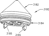
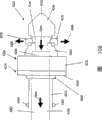
Fig. 1 has disclosed U.S. Patent No. 5,383, and a kind of plain edition injector apparatus 10 that discloses in 858, this device are used for liquid contrast agent is injected the vascular system of animal.Injector apparatus 10 has a front loading formula structure.The device of Fig. 1 adopts a kind of syringe 12, but can be by one first relieving mechanism 22 with this syringe from the antetheca 16 of the housing 18 of front loaded and infusion appliance 20 installation component 14 linked together.Need not the working pressure sheath, syringe 12 just can play the effect (although as what narrate in more detail below in conjunction with Figure 4 and 5, syringe can be used in the infusion appliance with pressure jacket) of injection operation.In disclosing consistent scope with this, the announcement that this paper will quote ' 858 patents as a reference, this patent has been transferred to the application's assignee Medrad limited company.
But please refer to the Fig. 1 and first relieving mechanism 22, installation component 14 is provided with roughly cylindrical interface 26, and this interface can be used for admitting the rear end of syringe 12.Interface 26 comprises an annular surface 28, and this surface can be cylindrical or conical.As Fig. 6 and 7 best shown in, annular surface 28 comprises a far-end ledge 29, the contact pin 30 on the rear end of this ledge and syringe 12 matches.Syringe 12 is inserted cylindrical interface 26, cooperate ledge 29 until contact pin 30, so that syringe 12 is fixed in infusion appliance 20.
Wherein, contact pin 30 equally is distributed in around the syringe syringe 12 and the attached power of ledge 29.Even syringe 12 pressure during use is distortion or " becoming ellipse " down, this also will help to keep being connected between syringe 12 and the ledge 29.This will overcome the potential deficiency of traditional front loading formula injector system, if become ellipse under the syringe pressure during use, described system is with inoperative.
Please refer again to Fig. 1, syringe 12 comprises an elongate tubular body or a sleeve pipe 32 and a co-axial discharging injection portion 34, and they are interconnection by a middle circle wimble fraction 36.One plunger 38 is positioned in the tubular body 32 slidably, but and can links to each other with second relieving mechanism 40 on the piston 42 in the infusion appliance housing 18.As what below will elaborate more, but the part of second relieving mechanism 40 constitute by plunger 38, constitute by piston 42 partially.
Piston 42 and plunger 38 are cooperated mutually, spray the fluid that is contained in the syringe 12 with required quantity and required speed.But second relieving mechanism 40 is designed to be convenient to plunger 38 to be moved axially along both direction when activating.No matter plunger 38 is positioned at any position of tubular body 32, the second releasable mechanism 40 can be designed so that also plunger 39 cooperates or break away from piston 42.In addition, in this connected, actuating mechanism moved back and forth plunger 38 in syringe tubulose body 32, and this actuating mechanism comprises piston 42 or drive member that can be reciprocal.In the reciprocating while, need not to make drive member or piston 42 to rotate.
Please refer to Fig. 1, for mounting of syringe, with the interface 26 in the syringe 32 insertion installation components 14.As Fig. 6 and 7 best shown in, contact pin 30 moves past annular surface 28 at first, their cooperate ledge 29 there, thereby syringe 12 is firmly held on the installation component 14.As Fig. 2 and 7 best shown in, installation component 14 also comprises the annular ring or the lasso 44 of projection forward, the effect of this lasso is vertical cooperation of guaranteeing between plunger 38 and the piston 42.Explain that as top the annular ring of projection or lasso 44 also play the effect of sealing between flange on the syringe 32 46 and the installation component 14 forward.
Elastic ring sealing flange 46 is around the tubular body 32 of syringe 12, and contact pin 30 is set to last preset distance, and this distance equates substantially with the width of annular surface 28.Thereby when the interface 26 that syringe 12 inserts in the installation component 14, when sealing flange 46 cooperated annular ring 44, annular ring 44 and flange 46 formed sealing between syringe 12 and installation component 14.
Above-mentioned installation setting has many advantages.During injection operation, contact pin 30 makes rocking of syringe 12 reduce to minimum with the attached of rear portion periphery of syringe 12.Make rock reduce to minimum in, contact pin 30 also can make syringe 12 rotate freely in interface 26.Contact pin 30 prevents that also syringe 12 breaks away from infusion appliance 20.Sealing between annular ring 44 and the flange 46 can prevent that also the contrast agent that overflows from the discharge end 34 of syringe 12 from flowing into 18 (as shown in Figure 2) of infusion appliance housing, and eliminates the structure corresponding component so that the needs of tolerance tension.For strengthening the sealability between flange 46 and the annular ring 44, can select to be provided with a suitable O shape ring (not shown) betwixt.
See also Fig. 1, device comprises that also a system, this system can be used for transmitting to infusion appliance controller 51 from syringe 12 information of syringe.Syringe 12 is provided with a code device 48, and this device is positioned at the front of contact pin 30, the back of flange 46.Code device 48 can be a bar code or any other is suitable, be the code device known to the skilled person in the art.When syringe 12 is attached to installation component 14, if syringe 12 rotation after contact pin 30 cooperates ledge 29 then is provided with a pick off 50 and reads code device 48 in annular surface 28.Pick off 50 sends coherent signal to infusion appliance controller 51 then, and this infusion appliance controller is explained signal and therefore revised the function of infusion appliance 20.Can comprise the volume, syringe 12 contained objects (being pre-charged with under the situation of syringe) of the size of syringe 12, syringe 12 in information encoded example on the code device 48, such as contrast agent flow speed and the pressure and the loading/injection sequence of manufacturing informations such as lot number, date and tool cavity (tool cavity) number, recommendation.
As the code device 48 of alternative bar code, code device 48 can also comprise projection or the recessed surface that machine readable is got.Read projection or recessed surface by the infusion appliance pick off 50 that is installed in the annular surface 28 in the similar mode that reads bar code then.Except code device 48, also can use the device (for example, slit, hole or projection on syringe 12 or the plunger 38) that mechanically reads, so that record conversion on installation component 14.Perhaps, can use the device (for example character, round dot and other geometry) that reads with optical mode to send the information of the employed injector type of intelligent circuit that relates to infusion appliance 20.
In Fig. 1, because the syringe 12 that uses among this embodiment does not have the pressure jacket that is used to strengthen and see syringe 12 contained objects, syringe 12 can be made by transparent PET polyester material.In another program, the wall of syringe 12 is made by polypropylene, can strengthen described wall by a series of circumferential ribs that vertically separate are set on the tubular body 32 of syringe 12.(Fig. 5 of ' 858 patents shows this setting).As what in ' 858 patents, discuss, suitably all ribs are separated (for example increment) by length to equate along tubular body 32, described all ribs can also realize being used for the fractionated dual function of volume, in order to realize the purpose of the contrast agent quantity in the indication syringe 12.
Please refer to Fig. 1 and 2, the tubular body 32 of syringe 12 also is provided with an indicating mechanism 52, and this indicating mechanism can be used for detecting easily the existence and the shortage of the liquid contrast agent in the syringe 12.In this case, testing agency 52 comprises a plurality of points that are integrally moulded in the band texture on the syringe 12, no matter syringe receiving fluids or air, and described naming a person for a particular job provides the vision indication.More particularly, when observing air and be background, put 52 ovalizes, but when observing the refractive index liquid contrast agent different and be background, put 52 rounded with air.In U.S. Patent No. 4,452, at length narrated the details of indicating mechanism 52 in 251, this patent has been transferred to the application's assignee Medrad limited company.In the scope consistent with this announcement, this paper will quote United States Patent (USP) 4,452, and 251 content as a reference.
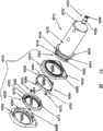
Fig. 3 shows the internal structure of syringe discharge end 34.Especially, though the rear portion 54 of discharge end 34 is the cone shape structure of convergent, the place ahead connector part 56 roughly cylindrical structures and constitute by the female thread 58 that is used for connection tube is attached to discharge end 34.In addition, the nozzle 60 of undergauge is arranged in the cylinder-shaped link part 56 with screw thread, and integrally moulded near the tapered rear 54 of position that taper and cylindrical part are combined and discharge end 34.
Figure 4 and 5 show another embodiment of the present invention, and wherein front loading formula syringe 112 is installed in the front portion of pressure jacket 170, and this pressure jacket is preferably made by firm transparent plastic, for example Merlon.Pressure jacket 170 is elongated tubular element form, is fitted into lasso on the installation component 124 by the flange with pressure jacket 170, the rear end of this member suitably can be installed in the installation component 124 on the housing antetheca 116.Pressure jacket 170 also has an open front end 172, and this front end can be used for admitting syringe 112.
In this embodiment, the annular surface 174 with a far-end ledge 175 is arranged near the open front 172 of pressure jacket 170.Annular surface 174 is structurally similar with the annular surface 28 among the embodiment shown in 7 to Fig. 1.Similarly, the tubular body 132 of syringe 112 comprises contact pin 180, and described contact pin is positioned at the position near its front end, and when tubular body 132 inserted pressure jacket 170, this front end matched with ledge 175.
In addition, the annular hand grip 162 of a pair of reinforcement is positioned at the front end of syringe 112, the relative both sides of discharge end 134, so that the operation of syringe 112, described handle and discharge end 134 and conical mid portion 136 are integrally moulded.In others, though do not disclose especially and narrate, should be understood that, can be optionally the multiple further feature of Fig. 1-3,6 and 7 embodiments of the invention that disclose be combined among the embodiment of Figure 4 and 5.
In use, the syringe 112 of Figure 4 and 5 can be installed in the pressure jacket 170, the piston 142 of infusion appliance 120 is in the punctured position shown in Figure 4, perhaps is in the propelling position shown in Figure 5.For example, as shown in figure 41, piston 142 is in the punctured position, and plunger 138 is arranged on the rear end of syringe 112.Then syringe 112 is inserted the opening 172 of the front end of pressure jacket 170, but match with plunger 138 until second relieving mechanism 140.
In Fig. 5, piston 142 is in the anterior position, and is except plunger 138 is in anterior position in the syringe 112 equally, that syringe 112 pressure jacket 170 of packing into is same as shown in Figure 4.In others, syringe 112 is contained on the pressure jacket 170 with before to combine the described process of Fig. 4 basic identical.Yet, as shown in Figure 5, make syringe plunger 138 and piston 142 be in its anterior position and have the advantage that some rear positions that surpass Fig. 4 are provided with.For example, because syringe plunger 138 and piston 142 have been in its anterior position, therefore need not to make them to move forward, so that air is displaced syringe 112, for syringe padding is prepared.On the contrary, plunger 138 and piston 142 are shunk immediately, with fluid inhalation syringe 112.Similarly, after finishing injection operation, shrink so that prepare, can save the extra time for next injection operation by not making plunger 138 and piston 142.
In a word, disclosed a kind of novel and improved system, syringe (for example syringe 12 among the embodiment of Fig. 1-3) can have been loaded onto infusion appliance housing 18 easily and/or unload from housing by this system.For realizing this purpose, but but first relieving mechanism 22 and second relieving mechanism 40 are cooperated mutually, so that simultaneously and/or form it independently and connect and separate accordingly, but can be with syringe 12 attached or unload infusion appliance housing 18, but can make the plunger 38 of syringe 12 connect or break away from the piston 42 of infusion appliance 20 drivingly by second relieving mechanism by first relieving mechanism.Another advantage is can plunger 38 be placed at any some place along its path to be driven or not driven state, make syringe 12 break away from infusion appliance 20 by this, and do not need to make piston 42 contractions or before piston 42 shrinks, at first make syringe 12 break away from the patient who is injecting.
But other desired characteristics of the present invention comprises the structure of first relieving mechanism 22, according to make rocking and break away from and reducing to viewpoint minimum and that eliminate the needs that make the manufacturing tolerance tension of syringe during injection operation, it is favourable with firm cooperation syringe 12 being installed on the infusion appliance housing 18.According to the viewpoint of " customization programming " that infusion appliance 20 is provided, it also is favourable that the code device 48 on the syringe 12 is cooperated mutually with the pick off 50 on the infusion appliance 20.According to the optimum visibility of syringe 12 contained objects, conduct heat and reduce because such as the contrast agent damage with pollute the required cleaning of pressure jacket and the viewpoint of maintenance, the elimination of pressure jacket also is desirable to the best of the contained object of syringe.
In order to eliminate the needs to pressure jacket, syringe 12 also can be made by firm relatively transparent plastic, and annular ribs (not shown) perhaps is set, and described rib can be separated to play the fractionated effect of volume.In addition, use the indicating mechanism 52 among Fig. 1 and 2 can be convenient to detect the existence of air in syringe 12, this indicating mechanism is molded in the syringe tubulose body 32 to put 52 form.What hold according to tubular body is air or liquid, and point 52 is shown as ellipse or circle respectively.But except the effect of a part as first relieving mechanism 22 that is used for syringe 12, syringe elastic ring flange 46 is also cooperated mutually with annular ring 44, as shown in Figure 2, form the sealing that prevents to flow into infusion appliance 20 from the contrast agent that the dispensing end of syringe 12 overflows.Embodiments of the invention shown in the Figure 4 and 5 provide a kind of system with multiple other advantage, described advantage comprises saves the time that syringe is filled and the syringe replacing is operated, this system can adopt pressure jacket to obtain described advantage, for example is installed in the pressure jacket 170 on the antetheca 116 of infusion appliance housing.
Fig. 6 shows and syringe 12 is being inserted infusion appliance 20 so that the sectional view of the syringe after the contact pin 30 cooperation ledges 29.The member that contact pin 30 is preferably roughly V-shaped, described member are preferably formed as a ring around the rear end of tubular body 32.Perhaps, one or more contact pin are set discretely around the rear end of body 32.Each contact pin 30 on the ring has one first end 62 and one second end 64 (Fig. 8 shows the amplification stereogram of the ring of contact pin 30).As shown in Figure 8, when syringe 12 inserted the interface 26 of infusion appliance 20, first end 62 of contact pin 30 cooperated ledge 29.Gap 66 around the periphery of tubular body 32 is separated from each other first end 62 of contact pin 30, so that they are softish and can compress easily.On the other hand, second end, 64 formation one of contact pin 30 are attached to the ring of tubular body 32.
Therefore, simply the rear end of tubular body 32 is inserted cylindrical interface 26, syringe 12 is linked to each other with infusion appliance 20 easily.Tubular body 32 is being inserted in the process of cylindrical interface 26, and first end 62 of annular surface 28 compression contact pin 30 is crossed ledge 29 until first contact pin 62.In case first end 62 is crossed ledge 29, they are opened elasticity and cooperate ledge 29, to prevent unloading tubular body 32 from interface 26.
Use a reciprocating type lasso 68 to unload syringe 12 from housing 20, this lasso is arranged in the infusion appliance 20, the rear of syringe 12 (in case inserting cylindrical interface 26).Shown in the arrow among Fig. 7, the cylindrical member that reciprocating type lasso 68 preferably can move in the forward and backward directions.During injection operation, reciprocating type lasso 68 is in the resting position of contact pin 30 back, so that first end 62 keeps and the cooperating of ledge 29.When finishing injection operation, in order to unload syringe 12 from interface 26, by an actuating mechanism (not shown) or manually push reciprocating type lasso 68 to ledge 29,, they can be easily skidded off from the back of ledge 29 so that it compresses first end 62.Can unload syringe 12 from infusion appliance 20 easily then.
Perhaps, shrink annular surface 28, can make contact pin 30 break away from ledge 29 by direction along the arrow among Figure 33 1100.For finishing this process, annular surface 28 is made of a plurality of fragments 1102, and all fragments are all collapsible so that releasing syringe 32.In another alternate embodiments shown in Figure 34, a part of inner surface 1104 moves inward along the direction shown in the arrow 1106, so that contact pin 30 condensations cause syringe 32 to break away from ledge 29.Skilled person in the art will be understood other embodiment of these two kinds of settings easily.
Will insert at syringe 112 under the situation of pressure jacket 170 (shown in Figure 4 and 5), the effect identical with contact pin 30 played in contact pin 180, certainly except their location towards the front end of syringe 112.In fact, if not the location of the contact pin 180 on the tubular body 132 can consider that contact pin 180 of the present invention has the structure identical with contact pin 30.When the opening 172 of excess pressure sheath 170 was inserted in contact pin 180, first end 62 of annular surface 174 compression contact pin 180 was crossed ledge 175 until them.Then syringe 112 is held in place securely.In that become must be when pressure jacket 170 unloads syringe 112, a reciprocating type lasso 68 extends (below will narrate in more detail) forward to compress first end 62, so that they no longer cooperate ledge 174 in pressure jacket 170.Can unload syringe 112 from pressure jacket 170 then.
Yet contact pin 30,180 needn't have the V-arrangement outward appearance shown in Fig. 1 and the 4-8.As shown in Figure 9, second embodiment that can consider contact pin 30 has b shape outward appearance.When contact pin 30 had b shape outward appearance, the end one of they and syringe 412 constituted.When contact pin 30 had b shape outward appearance, they had from first end 70 of second end, 72 outward extending bulb shapes, gap 71 (as Figure 14 and 15 best shown in) with as described in second end and adjacent contact pin 30 separate.Identical with first end 62, when syringe inserted infusion appliance housing 18, first end 70 cooperated ledge 29.Identical with first end 62, will be when infusion appliance 20 unloads syringe 412, the reciprocating type lasso 68 that acts on first end 70 makes their break away from ledge 29.
Each embodiment of the contact pin of considering for the present invention 30, what also can consider is when keeping within the scope of the invention, can change the quantity of used contact pin.For example, for syringe 212, shown in Figure 10 and 11, can consider only a contact pin to be set at the place, end of syringe.Contact pin 30 with first end 70 and second end 72 only is shown in Figure 10 and 11.Yet, should be understood that, can replace having the contact pin 30 of first end 62 and second end 64 with it easily.
Because contact pin should be crooked to play the best use of, though therefore can use single contact pin 30, preferably uses at least two contact pin.Syringe 312 with at least two contact pin has been shown among Figure 12 and 13.When two contact pin are included on the syringe 312, can consider they are arranged on the relative both sides of tubular body 32, with the stability of increase syringe 312 with the secure fit of infusion appliance 20.Contact pin has suitable shape, and has different arbitrarily circumferential size.
In another embodiment of pressure jacket injector system shown in Figure 32, consider that syringe lid 1000 can be arranged on the place, end of pressure jacket 1002, to keep syringe 1032 wherein.Perhaps, lid 1000 can be attached to syringe 1032 or be molded as the part of syringe, and does not need to become a separating member.Shown in figure 32, pressure jacket 1002 is modified version of the pressure jacket 170 shown in the Figure 4 and 5.According to purport of the present invention, lid 1000 is included in the contact pin 1004 around its periphery.The ledge 1006 that contact pin 1004 cooperates around the end of pressure jacket 1002.Slide along the outside of pressure jacket 1002 for making contact pin 1004 break away from ledge 1006, one reciprocating type rings 1008.Ring 1008 comprises a conical surface 1010, so that unload low splicing 1004 from ledge 1006.The actuator of ring 1008 is not shown among the figure.Yet skilled person in the art will easily be understood, can be manually, machinery or the operation ring 1008 that electrically (perhaps is fit to make contact pin 1004 to break away from the mode of ledges 1006 with any other).
In the another alternate embodiments of the device of narrating in conjunction with Figure 32, contact pin can be extended from lid (it can separate, be attached to syringe or integrally moulded with syringe with syringe), use with the embodiment shown in the Figure 4 and 5 in contact pin 180 cooperate the identical method of annular construction member 174, at place, the end cooperation annular construction member 174 of pressure jacket 170.With in conjunction with identical shown in the Figure 4 and 5 with described embodiment, then reciprocating type lasso is positioned in the pressure jacket 170, so that contact pin breaks away from annular construction member.
The element that is used for relieving mechanism has been shown among Figure 38 and 39.Reciprocating type lasso 1402 shown in being somebody's turn to do is in the inside of pressure jacket 170.As shown in the figure, reciprocating type lasso 1402 is arranged on the place, end of at least two supporting members 1404, and described supporting member also is positioned at the inside of pressure jacket 170.In order to admit supporting member 1404, the inwall 1406 of pressure jacket 170 comprises at least two tracks 1408, and supporting member 1404 slides in described track.Will be when pressure jacket 170 unloads syringe 1032, reciprocating type lasso 1402 moves forward in pressure jacket 170, so that the cooperating of the contact pin disengaging on the syringe 1032 and annular construction member 174.
Can also in conjunction with shown in the Figure 4 and 5 and described pressure jacket system use this setting.Will be when pressure jacket 170 unloads syringe 132, reciprocating type lasso 1402 moves forward in pressure jacket 170, and compression contact pin 180 is so that they no longer cooperate annular construction member 174.In case annular construction member 174 is crossed in contact pin 180, can unload syringe 132 from pressure jacket 170.
Will insert at syringe 112 under the situation of the pressure jacket 170 shown in the Figure 4 and 5, and can use the mode identical b shape contact pin 190 to be added the front end of syringes 112 with using contact pin 180.As shown in figure 16, contact pin 190 consists essentially of a ring 74, and this ring extends along backward directions from the second end 72 of contact pin 190.As shown in figure 17, the V-shaped structure of ring 74 formation one cross sections that has contact pin 190.Identical with contact pin 180, insert pressure jacket 170 (shown in Figure 4 and 5) when contact pin 190, they will be compressed until them and cross annular surface 174, so they stretch to cooperate ledge 175.Contact pin 190 is firmly held in syringe 112 in the pressure jacket 170, until breaking away from by reciprocating type lasso 68.
Figure 18-20 shows the installation and removal of syringe 412.In Figure 18, show the syringe 412 before inserting infusion appliance antetheca 16.After contact pin 30 is crossed annular surface 128 and leaned against on the far-end ledge 129, the illustrated reciprocating type lasso 68 that is in the resting state will be still in after first end 70 of contact pin 30.In this embodiment, illustrated annular surface 128 has conical cross-section, rather than the cylindrical cross section shown in Fig. 7 and 9.Because taper helps to push first end 70 of contact pin 30 in the process of syringe 412 insertion infusion appliancees 20, so conical cross-section is convenient to syringe 412 insertion interfaces 26.In addition, when annular surface 128 convergents, this annular surface can be used as the guide surface that is used for syringe 412 (or any other embodiment that discloses), and more the method for wide-angle also can be with syringe 412 insertion antethecas 16 even use.In other words, even when syringe 412 accurately not being oriented the central axis of interface 26, also syringe 412 can be inserted antetheca 16 easily.
As shown in figure 19, in case syringe 412 is inserted antetheca 16 fully, contact pin 30 is stretched to cooperate ledge 129.Then syringe 412 is held in place securely.As shown in figure 19, reciprocating type lasso 68 remains in its resting position, after finishing injection operation.
After finishing injection operation, move forward reciprocating type lasso 68, first end 70 of compression contact pin 30 is so that contact pin 30 breaks away from ledge 129.Figure 20 shows the reciprocating type lasso 68 that is in this forward facing position.Also illustrate the compression of contact pin 30.Can unload syringe 412 from infusion appliance 20 then.
The present invention is connected in jointer 500 with syringe before also considering and being preferably in syringe and infusion appliance 20 links to each other.To understand as skilled person in the art, jointer can be disposable or reusable.To understand as skilled person in the art, syringe can have the structure different with the announcement of this paper.Authorized on July 16th, 1996 in people's such as Hoover the U.S. Patent No. 5,535,746 and narrated a kind of jointer that is used for syringe, this paper will quote it and disclose as a reference.Other patent of demonstration jointer comprises U.S. Patent No. 5,520,653 and WO 97/36635, and they are all transferred the possession of the assignee in the application, and this paper will quote these patents as a reference.
In the embodiment shown in Figure 21, syringe 412 has the contact pin 30 of b shape outward appearance, and this syringe snap-fit is gone into the front end 502 of jointer 500.Certainly, can be as an alternative with contact pin with V-arrangement cross section.Jointer 500 comprises an annular surface 528, and this surface has a far-end ledge 529 in its front end 502, and first end 70 of contact pin 30 cooperates this front end, so that syringe 412 is held in place securely.The flange 46 of syringe 412 comprises or does not comprise with the front end 502 of jointer 500 and matches, if seepage is arranged, can prevent that contrast agent from entering infusion appliance housing 18 by jointer 500.The rear end 504 of jointer 500 preferably also comprises a flange 546, and the annular ring 44 on the installation component 14 of this flange and infusion appliance 20 matches.Flange 546 plays and the identical effect of flange 46 on the syringe 12, prevents that promptly contrast agent (perhaps being included in any fluid in the syringe) from entering infusion appliance 20.
If jointer 500 is attached to syringe 32, needs piston 42 to connect and be equipped with the adaptation length that total increased.If so, will understand, a piston extension device or jointer (not shown) will be attached to the end of piston 42 as skilled person in the art.Perhaps, piston 42 can be configured to the syringe 32 that its length is enough to be fit to different length.
In this specific embodiment, jointer 500 comprises traditional connector 506, for example in U.S. Patent No. 5,535,746 or U.S. Patent No. 5,383,858 in the narration connector.Design like this, jointer 500 can make syringe 412 be connected in infusion appliance, and this infusion appliance is designed to only admit the syringe with traditional connector 506.
As shown in figure 22, in another embodiment of jointer, traditional syringe must be connect in the infusion appliance that fits over admittance syringe of the present invention.Here, jointer 600 is included in the contact pin 630 at 604 places, its rear end.The effect of contact pin 630 and function class are like the contact pin 30 of jointer being fixed in housing 18 by the ledge 29 that cooperates on the installation component 14.Make contact pin 630 break away from ledge 29 by reciprocating type lasso 68.Jointer 600 also comprises a flange 646, and this flange is identical with flange among other embodiment that the front has been narrated.Though having one, shown jointer 600 inserts syringe wherein, that have a ridged end, but should be understood that, jointer 600 can be designed to easily its front end 602 and can hold traditional connector, for example U.S. Patent No. 5,535,746 or U.S. Patent No. 5,383,858 in the narration connector.
Figure 23 and 24 shows the axonometric chart of the combination of two syringes 412 and jointer 600.In this embodiment, omitted flange 46.Yet, as shown in figure 22, can comprise flange 46.Certainly, identical with syringe 312 (shown in Figure 12 and 13) with syringe 212 (shown in Figure 10 and 11), jointer includes only a contact pin, two contact pin or more than two contact pin 630.Figure 23 and 24 shows the jointer 600 with a plurality of contact pin.
But will be used to cooperate and two embodiment of second relieving mechanism 40 of releasing syringe plunger and infusion appliance piston in conjunction with Figure 25-29 narration now.Figure 25 shows the electromagnetic type relieving mechanism.Figure 26-29 shows the electrodynamic mechanical type relieving mechanism.
As shown in figure 25, by a calutron plunger 738 is connected in piston 742 releasedly.The front end 702 of piston 742 is provided with a solenoid 704, can make this solenoid actuated by using an electric current that passes the electrified wire 706 of piston 742.707 places in its back-end, plunger 738 comprises the magnetic attraction ring 708 that a usefulness ferrum is made, and for example attracts the suction rings of solenoid 704 when solenoid 704 activates.The cross section of the recess 710 in the front end 702 of piston 742 and the rear end 707 of plunger 738 all is columniform.This can make piston 742 and plunger 738 cooperate with syringe in the orientation of plunger 738 irrelevant.
As shown in figure 25, but the operation of second relieving mechanism 40 is as follows.When the interface that syringe is inserted on the infusion appliance housing 18, piston 742 extends into syringe, matches with the recess 710 of plunger 738 until its front end 702.Solenoid 704 is activated, so that plunger 738 shrinks.During piston 742 moved backward, the captivation between magnetic attraction ring 708 and the solenoid 704 made plunger 738 remain in the end of piston 742.Perhaps, solenoid 704 is activated, so that match with plunger 738.In case plunger 738 and piston 742 are attracted each other with electromagnetic mode, as required mobile piston 742 in syringe.For making piston 742 break away from plunger 738, piston 742 is shunk, only need to disconnect the power supply that offers solenoid 704.Certainly, piston 742 can advance plunger 738, for example during injecting, and solenoid 704 is activated.
Be but that second embodiment that second relieving mechanism 40 is considered comprises that piston is connected with motor machine between the plunger.Figure 26-29 shows this embodiment.
In Figure 26-29, piston 842 has a front end 802, matches in recessed regional 804 in this front end and the rear end 806 that is formed on plunger 838.The front end 802 of piston 842 comprises several projections 808, and described projection is extended from this collapsiblely.As shown in figure 27, projection 808 cooperates recess or the groove 810 that forms in the plunger 838.Piston 842 and front end 802 closure members 812.The mechanism 814 that is contained in equally in the piston 842 can make member 812 activate.Mechanism 814 accepts electric power by lead 816.
Shown in Figure 28 and 29, projection 808 is roughly rectangular.They are connected to each other by elastic component 818.As shown in figure 29, elastic component 818 bias voltage projections 808 are so that they can't be from front end 802 projections of piston 842.
But now will be in conjunction with the operation of Figure 26-29 narration second relieving mechanism 40.When syringe was inserted the antetheca 16 of infusion appliance 20, piston 842 extended forward to run into plunger 838.As shown in figure 29, when piston 842 extended forward, mechanism 814 did not activate, so that member 812 is in the contraction state.In other words, contraction members 812 is not so that it is between projection 808.As a result, as shown in figure 29, elastic component 818 bias voltage projections 808 are so that they can't extend to the outside of the front end 802 of piston 842.
In case recessed regional 804 in the front end 802 of piston 842 and the plunger 838 matches, mechanism 814 activates, so that member 812 extends forward, between projection 808, forces projection 808 to extend to the outside of the front end 802 of piston 842 by this.In case extend projection 808, described projection will extend into the groove 810 in the plunger 838.In case be provided with like this, piston 842 links to each other with plunger 838 so that piston 842 move backward that directly to change into plunger 838 mobile backward accordingly.
Break away from infusion appliance or piston 842 contractions are become in case of necessity at syringe, mechanism 814 is activated, so that member 812 withdraws between projection 808.In case withdraw from, elastic component 818 bias voltage projections 808 are so that their mating grooves 810 no longer.Piston 842 is withdrawed from from plunger 838.
But now in conjunction with two other second relieving mechanism 40 of Figure 35-37 narration.
In embodiment shown in Figure 35, the stretching, extension of the elastomeric elements 1202 by being arranged on its front end place makes plunger 1238 be connected in piston 1242 releasedly.Elastomeric elements 1202 is one to have the cylindrical elements of outer wall 1204 and inwall 1206.One bar 1208 passes piston 1242 and extends, and links to each other with actuator 1210 at the front end place of the bar 1208 of the most close plunger 1238.Actuator 1210 has frusto-conical in the face of on the side of elastomeric elements 1202.Frusto-conical limits an inclined plane 1212 on actuator 1210.The diameter of elastomeric elements 1202 is slightly less than the diameter in the hole 1214 in the plunger 1238.Equally, the diameter of actuator 1210 is less than the diameter in hole 1214.
But will narrate the operation of second relieving mechanism 40 shown in Figure 35 now.Because the diameter in the hole 1214 in the plunger 1238 is greater than the diameter of actuator 1210 and elastomeric elements 1202, therefore when promoting piston 1242 forward, elastomeric elements 1202 and actuator 1210 are easy to assemble hand-hole 1214.Then, by not existing the piston 1242 that connects cooperation can advance plunger 1238 therebetween.Yet, shown in the arrow among Figure 35 1216,,, actuator 1210 is pulled to elastomeric elements 1202 by bar 1208 in order to be connected cooperation (for example making plunger retraction) with plunger 1238 in case locate in this mode.From the pressure compresses elastomeric member 1202 of actuator 1210, so that expand from their not stressed states or stretch in the outside 1204.Show the general shape of the expansion wall 1218 of elastomeric elements 1202 among Figure 35 with dashed line form.The wall 1220 of expansion wall 1218 mating holes 1214 is so that piston 1242 cooperates plunger 1238 releasedly.Plunger 1238 is shunk, for example with the fluid inhalation syringe.
But will narrate the embodiment of second relieving mechanism 40 shown in Figure 36-37 now.Shown in Figure 36-37, plunger 1338 is by fragment member 1302 fitting pistons 1342.Fragment member 1302 is made of the resolution element 1304 shown in the end-view of a plurality of Figure 37.Resolution element 1304 can be made by any suitable material, and elastomeric material for example as long as material best (1) can bear repeated deformation and (2) basically when it no longer is subjected to distortional stress, is replied its original state basically.Fragment member 1302 is arranged at the front end of piston 1342.One bar 1306 passes the centre of piston 1342 and stretches into the centre bore 1308 of fragment member 1302 at least in part.
For plunger 1338 is linked to each other releasedly with piston 1342, piston 1342 moves forward, in fragment member 1302 is arranged on the hole 1310 that forms in the plunger 1338.Bar 1306 is moved forward along the direction shown in the arrow 1312, be at least partially disposed in the fragment member 1302 until bar 1306.Because the diameter of bar 1306 greater than the diameter in hole 1308, therefore can outwards promote fragment member 1304 with bar 1306 patchholes 1308, arrives among Figure 36 and Figure 37 with the deformation position shown in the dotted line 1314 until them.In when distortion, fragment member 1304 cooperates the wall 1316 in the hole 1310 in the plungers 1338, so as between plunger 1338 and piston 1,342 one releasable cooperation of formation.
But for each second relieving mechanism described in Figure 25-29 and the 35-37, the advantage that mechanism provides is that plunger need not come directed piston in any specific mode, so that being connected between piston and the plunger.Irrelevant with the orientation of piston and plunger, both can cooperatively interact easily, and can break away from mutually easily.
In addition, if for example the syringe that will fill in advance is installed on the infusion appliance, needn't make the plunger retraction in the syringe just can be the fluid in the injection absorption syringe subsequently.Under this kind situation, piston can move in " the only pushing away " pattern that cooperates that does not need between piston and the plunger.If move in this kind mode, matching mechanism does not need to activate.Perhaps, if infusion appliance is designed to the pre-syringe of filling of only control, then need to be provided with the mechanism that is not easy to discharge.
Plunger of the present invention also comprises a pressure transducer, and similar 1998 JIUYUE of this pick off were authorized people such as little Nolan on the 15th and transferred the possession of the pick off of narration in the application's assignee's U.S. Patent No. 5,808,203.In the scope consistent with this announcement, this paper will quote U.S. Patent No. 5,808, and 203 announcement as a reference.
Figure 30 and 31 shows the pick off that can be included in the plunger of the present invention.Plunger 938 preferably includes a pedestal 902, and this pedestal has a passage 904 that runs through wherein.One detection means 906 is arranged in the passage 904, so that contact with a part of P of contact surface 908 in operation.Preferably make detection means 908 bias voltage forward, for example by a spring 910.As shown in figure 31, along with the increase of the fluid pressure in the syringe (not shown), the part P of contact surface 908 distortion.The distortion of this part P makes detection means 906 move backward by 912 and 914 in passage 904 and the piston 942.The pick off 916 that use is preferably disposed in the piston 942 is monitored moving of detection means 906.Because the mobile degree of detection means 906 is functions of the pressure of the fluid media (medium) in the syringe, therefore can be from wherein determining the pressure of fluid media (medium).Preferably pick off 916 is linked to each other with a data collection and/or control device by lead 918.
Though Figure 30 and 31 has narrated a possible embodiment of the pick off that can be combined in the plunger of the present invention, should be noted in the discussion above that to comprise any suitable pick off.In addition, pick off does not need the pressure of a test fluid.Understand as skilled person in the art, pick off can be measured many different parameters, comprise amount of fluid, pressure and density in the syringe.
Equally, plunger comprises encoder element, reads or detect described encoder element by infusion appliance or infusion appliance piston, includes object with identification syringe and/or its.In this embodiment, encoder element (for example integrated circuit) is included on the plunger, rather than on the syringe.Then when the plunger contact piston, read encoder element with the method for electronics.Plunger comprises the information such as object and volume that include such as syringe, and process or the required out of Memory of book keeping operation purpose.An example of this system is the system of narrating among the open No.WO99/65548 of PCT, and this paper will quote this patent as a reference.
Here usually use term " cooperation of syringe interface and syringe " to represent with described the present invention shown in.Term used herein " syringe interface " and " some syringe interfaces " can be combined with the new medical infusion appliance or constitute one, be configured to perhaps to install or to unite that (for example U.S. Patent No. 5 at existing or traditional medical injector, 383, shown in 858 and described infusion appliance, this paper will quote its content as a reference) on the syringe jointer so that syringe of the present invention is mounted thereon.
Figure 40 A-40C shows the another embodiment of front loading formula syringe interface of the present invention and injector system 1500.System 1500 comprises a syringe 1512 and a syringe interface 1514.Syringe 1512 comprises body or the sleeve portion 1516 with a rear end 1520 and a front end 1517, and this front end limits a fluid discharge end 1518.Preferably that 1520 places, rear end of at least one contact pin or installation component 1522 and syringe 1512 or near sleeve portion 1516 are linked together.In addition, as U.S. Patent No. 5,383, what more be described in detail in 858 is such, preferably flange 1524 is positioned at the front of installation component 1522, enters syringe interface 1514 and infusion appliance (not shown) from the fluid that the discharge end 1518 of syringe is discharged so that syringe 1512 matches with syringe interface 1514 and/or prevents.
Preferably installation component 1522 is arranged on around the girth of sleeve portion 1516, and comprises that one limits the inclined plane 1526 of shoulder 1528.To be described in detail the effect of installation component 1522 below.Perhaps, 1522 extensions on every side at a part of girth of sleeve portion 1516 of installation component perhaps form discontinuous fragment.
Unless (otherwise point out, the syringe of narrating above 1512 (and member) be applied to all the other embodiment of the present invention that discuss and narrate below in conjunction with Figure 40 A-47F.)
As Figure 40 A and 40C best shown in, syringe interface 1514 is in " opening " position, to prepare to admit syringe 1512.Syringe interface 1514 comprises the syringe retaining member 1532 of a base component 1530 and two cooperations.Yet, in alternative embodiment, three or more retaining member 1532 can be set.Each retaining member 1532 is preferably linked together by two inclined plane members 1534 and base component 1530.Yet, in alternative embodiment, can use one, three or more member 1534, so that each retaining member 1532 is linked together with base component 1530.
In addition, each retaining member 1532 is preferably formed as a mating surface 1533 and a groove 1536, so that installation component 1522 is caught and remained on the syringe 1512.In addition, retaining member 1532 is preferably united mutually by two track components 1538.Equally, in alternate embodiments, can use one, three or more track component 1538, so that retaining member 1532 is united mutually.
For syringe 1512 is installed on the syringe interface 1514, syringe 1512 axially (direction of the arrow A in Figure 40 A) moves into the space that forms between the retaining member 1532.When the contact surface 1533 on the 1524 cooperation retaining members 1532 of the flange on the syringe 1512, impel retaining member 1532 to move to base component 1530 along track component 1534.Because track component 1534 centroclinal to base component 1530, so the operation of track component 1534 can make retaining member 1532 move along track component 1538 mutually, and around the rear end 1520 of syringe 1512 " condensation ".Along with retaining member 1532 condensations on syringe 1512, retaining member 1532 is cooperated mutually, installation component 1522 is captured in the groove 1536, so that syringe 1512 and syringe interface 1514 secure fit.
As known in the art, the locking mechanism (not shown) of any suitable type can be used to retaining member 1532 is fixed together, so that syringe interface 1512 remains in the syringe interface 1514.In order to unload syringe 1512 from syringe interface 1514, lock is unclamped, and retaining member 1532 is removed (for example, with hands by lever or any other is suitable, the control device approved by the present technique field), so that installation component 1522 releasing slots 1536.
The another embodiment of syringe interface and injector system 1600 has been shown among Figure 41 A-41D.System 1600 comprises a syringe 1512 and a syringe interface 1614.As Figure 41 B and 41C preferably shown in, syringe interface 1614 is in " opening " position, to prepare to admit syringe 1512.Syringe interface 1614 comprises the syringe retaining member 1632 of a base component 1630 and two cooperations.Retaining member 1632 preferably links together by a trunnion 1631 or other suitable mechanism (seeing Figure 41 D), and linked together with base component 1630.In addition, retaining member 1632 is linked together by pin 1629 (seeing Figure 41 D) and base component 1630, and pin 1629 and retaining member 1632 are linked together and be trapped in the slit 1635 that limits in the base component 1630.
In addition, each retaining member 1632 preferably defines a groove 1636, so that installation component 1522 is caught and remained on the syringe 1512.As Figure 41 B and 41C best shown in, spring catch 1637 (or other suitable locking mechanism) links to each other with a retaining member 1632, and limits the groove with pin recess 1640 in another retaining member 1632.In addition, preferably define two sleeve pipe guide rails 1639 in the base component 1630.
For syringe 1512 is installed on the syringe interface 1614, syringe 1512 (direction of the arrow B in Figure 41 B) downwards moves into the space that forms between the retaining member 1632.By the sleeve pipe guide rail 1639 in the base component 1630 sleeve pipe 1516 of syringe 1512 is introduced position between the retaining members 1632.When syringe sleeve 1516 cooperates the pivot pin end 1651 of retaining member 1632 (seeing Figure 41 C), impel the on every side condensation of retaining member 1632 in the rear end 1520 of syringe 1512.Be placed in the base component 1630 pin 1629 in the slit 1635 that limits with the arcuate movement guiding of retaining member 1632 and be controlled to be engaged in syringe 1512 around.Along with retaining member 1632 condensations on syringe 1512, retaining member 1632 is cooperated mutually, installation component 1522 is captured in the groove 1636, so that syringe 1512 and syringe interface 1614 secure fit.
In addition, when retaining member 1632 condensations around the syringe 1512 time, spring catch 1637 moves along groove, and is locked in the pin recess 1640, so that syringe 1512 is fixed in the syringe interface 1614.In order to unload syringe 1512 from syringe interface 1614, must unload spring catch 1637 from pin recess 1640, so that retaining member 1632 unclamps, and with retaining member 1632 from shift out (for example, with hands or any suitable leverage) with cooperating of syringe 1512.In this, can be by upwards (along the rightabout of arrow B) or axially (direction of the arrow C in the 41B) mobile syringe 1512 syringe 1512 is unloaded.
Figure 42 A-42D shows another embodiment 1700 of syringe interface shown in Figure 41 A-41D and injector system 1600.System 1700 comprises a syringe 1512 and a syringe interface 1714.As Figure 42 C and 42D best shown in, the difference of the syringe interface 1614 among syringe interface 1714 and Figure 41 A-41D is that retaining member 1732 comprises pivot pin end 1751, this pivot pin end is positioned at the end away from the retaining member 1732 of trunnion 1731.In addition, shown in Figure 42 D, retaining member 1732 best fexible bias pressures are in " closure " or " cooperation " position, so that syringe 1512 remains in the syringe interface 1714.
For syringe 1512 is installed on the syringe interface 1714, syringe 1512 (direction of the arrow D in Figure 42 B) downwards is moved into retaining member 1732 and matches.When syringe sleeve 1516 cooperates the pivot pin end 1751 of retaining members 1732, impel retaining member 1732 to head on elastic force separately, so that syringe sleeve 1516 is by between the pivot pin end 1751, and enter the space that limits between the retaining member 1732.By the groove 1736 guiding syringe installation components 1522 that limit in the retaining member 1732, so that syringe 1512 correctly is positioned in the syringe interface 1714.In case syringe 1512 is by pivot pin end 1751, elastic force impels retaining member 1732 condensations around the rear end 1520 of syringe 1512.Be placed in pin 1729 in the slit 1735 that base component 1730 limits with the arcuate movement guiding of retaining member 1732 and be controlled to be engaged in syringe 1512 around.Along with retaining member 1732 condensations on syringe 1512, retaining member 1732 is cooperated mutually, installation component 1522 is captured in the groove 1736, so that syringe 1512 secure fit are in syringe interface 1714.
In order to unload syringe 1512, against the pivot pin end 1751 of retaining member 1732 (along the rightabout of arrow D) mobile syringe 1512 upwards from syringe interface 1714.When the upwards active force on the syringe 1512 overcomes when making the elastic force that retaining member 1732 combines, retaining member 1732 will separate, and make syringe 1512 syringe interface 1714 that slips away.
Figure 43 A-43I shows the another alternate embodiments 1800 of syringe interface shown in Figure 41 A-42D and injector system 1600,1700.System 1800 comprises a syringe 1512 and a syringe interface 1814.As Figure 43 B and 43H best shown in, the difference of the syringe interface 1614,1714 among syringe interface 1814 and Figure 41 A-42D is that retaining member 1832 comprises extended member 1855 and rounding 1857.Preferably handle extended member 1855 so that retaining member 1832 moves to open position (promptly resist and make retaining member 1832 remain on elastic force in the make position).The inclined plane 1526 of the installation component 1522 of syringe 1512 operationally cooperates rounding 1857 so that retaining member 1832 opens, and make syringe 1512 axially (direction of the arrow E in Figure 43 C) be installed on the syringe interface 1814.All the other structures of syringe interface 1814 are similar substantially or identical with the structure of said syringe interface 1714.
As Figure 43 E best shown in, can use with the described essentially identical method of the top Figure 42 of combination A-42D and come mounting of syringe 1512, and unload this syringe from syringe interface 1814.In addition, yet, as Figure 43 A, 43C, 43F and 43G best shown in, axial mounting of syringe 1512 and unload this syringe from syringe interface 1814.Therefore, syringe interface 1814 is fit to the method for two kinds of attaching/detaching syringes 1512.
For axial mounting of syringe 1512, syringe 1512 is inserted syringe interfaces 1814, cooperate retaining members 1832 until installation component 1522.The rounding 1857 that the inclined plane 1526 of installation component 1522 cooperates on the retaining member 1832 forces retaining member 1832 to head on elastic force separately by this.After installation component 1522 is crossed the rounding zone, retaining member 1832 condensations and with installation component 1522 be captured in groove 1836 around so that syringe 1512 is fixed in syringe interface 1814.
In order axially to dismantle syringe 1512, handle the extended element 1855 (that is, common pressurization) of retaining member 1832, to overcome elastic force and to impel retaining member 1832 separately.When the installation component 1522 that is moved apart syringe 1512 when retaining member 1832 is not engaged in degree in the groove 1836, can be from the syringe interface 1814 axial dismounting (along the direction opposite) syringe 1512 with arrow E.
Figure 44 A and 44B show first embodiment of the varied slightly of the syringe interface 1814 shown in Figure 43 A-43I, described syringe interface in conjunction with or be installed on the infusion appliance head.Syringe interface 1914 functional and top described similar substantially or identical in conjunction with syringe interface 1814.
Figure 45 A and 45B show second embodiment of the varied slightly of the syringe interface 1814 shown in Figure 43 A-43I, described syringe interface in conjunction with or be installed on the infusion appliance head.Syringe interface 2014 functional and top described similar substantially or identical in conjunction with syringe interface 1814.
Figure 46 A-46D shows first preferred embodiment of front loading formula syringe interface of the present invention and injector system 2100.System 2100 comprises a syringe 1512 and a syringe interface 2114.As Figure 46 A best shown in, syringe interface 2114 comprises a softish retaining ring 2150, this retaining ring is arranged between back plate 2152 and the header board 2154.Retaining ring 2150 limits a back ledge 2160, and when syringe 1512 was installed in the syringe interface 2114, back ledge 2160 was suitable for cooperating the installation component 1522 of syringe 1512.
Ring 2150 comprises at least one but preferably two release components 2156 and at least one but two haunched members 2158 preferably.In addition, as what below will be described in detail, the shape of ring 2150 is preferably oval, so that can cooperate with the installation component 1522 of syringe 1512 and break away from.As Figure 46 B-46D best shown in, release component 2156 is from back plate and header board 2152,2154 projections so that handle such as the operator, releasing syringe 1512 from syringe interface 2114.In addition, haunched member 2158 is hunted down and slides in the groove (not shown) that limits in the (not shown) of the back side of header board 2154, in the time can only handling a release component 2156 and replace two release components 2156, can from syringe interface 2114, unload syringe 1512.(narrate and at all grooves shown in Figure 47 E below in conjunction with another embodiment of Figure 47 A-47F.)
For syringe 1512 is installed on the syringe interface 2114, syringe 1512 axially (direction of the arrow F in Figure 46 C) is moved into syringe interface 2114 and matches.When installation component 1522 cooperated retaining member 2150, installation component 1522 impelled softness, oval-shaped ring 2150 to become a more rounded structure, made installation component 1522 move past ring 2150 by this.After installation component was by ring 2150, ring 2150 was replied its original shapes, catches installation component 1522 in the back of ledge 2160 thereafter by this, and syringe 1512 is fixed in syringe interface 2114.
During the syringe installation and removal, be provided with haunched member 2158 and groove (not shown), with the motion of control/restriction retaining ring 2150.More particularly, during syringe installation and removal, by the haunched member 2158 that can in groove, slide guide with the motion of control loop 2150 (that is, and from substantially oblong-shaped to roughly rounded, and oppositely).Therefore, irrelevant with the orientation during the initial mating of syringe 1512 and retaining ring 2150, haunched member 2158 and all grooves bootable and the syringe power of restriction on ring 2150 and the compound motion of ring 2150.
In order to unload syringe 1512 from syringe interface 2114, inwardly compress one or two release component 2156 (that is) towards the center of syringe interface 2114, force by this ring 2150 from the cooperating of the installation component 1522 of syringe 1512 throw off.When release component 2156 activates, promptly and move axially (rightabout of the arrow F in Figure 46 C) syringe 1512, so that unload syringe 1512 from syringe interface 2114.
When release component 2156 activated, haunched member 2158 slided in the groove (not shown), and the motion of guided rings 2150 becomes roughly rounded structure from substantially oblong-shaped structure, so that installation component 1522 breaks away from the back ledge 2160 of ring 2150.
Be understandable that present embodiment can use simply, the axially-movable of single step is installed in syringe 1512 on the syringe interface 2114.In order to unload syringe 1512, compress one or two release component 2156, and from syringe interface 2114, axially unload syringe 1512 simply.
Figure 47 A-47F shows another embodiment 2200 of the system 2100 shown in Figure 46 A-46D.The structure of system 2200 and effect are identical with said system 2100 basic class Sihes among Figure 46 A-46D, except release component 2256 is obviously amplified so that handle be more prone to and simple.
Discussed in conjunction with Figure 46 A-46D as top, Figure 47 E shows the groove 2270 that is formed in the header board 2254 and is captured in haunched member 2258 in the groove 2270.
Figure 48 A-48C shows the another embodiment of front loading formula syringe interface of the present invention and injector system 2300.System 2300 comprises a syringe 2312 and a syringe interface 2314.With different in conjunction with the syringe that other embodiment discussed and narrated 1512 of syringe interface of the present invention shown in Figure 40 A-47F and injector system, syringe 2312 preferably includes (except other member of syringe 1512) and is formed on two grooves 2327 in its rear portion.Perhaps, can form one, three or many grooves 2327 in the syringe 2312.
Syringe interface 2314 preferably includes a base component 2360 and a rotatable collet chuck member 2362 that is installed in the base component 2360.As what below will be described in detail, base component 2360 preferably includes two insertions dowel 2364 wherein.Collet chuck member 2362 comprises that a plurality of fragment member or tang 2368, that are formed on wherein are limited to spiral path 2370 in its rear end and at least two pillars 2372 that operationally cooperate the groove 2327 in the syringe 2312.Be preferably, for following reason, the appropriate position in spiral path 2370 (for example, or near its terminal) forms small-sized ratchet 2374.By dowel 2364 collet chuck member 2362 is remained in the base component 2360, described dowel is hunted down and is placed in the spiral path 2370 in the collet chuck member 2362.
For syringe 2312 is installed on the syringe interface 2314, the pillar 2372 that groove 2327 on the syringe 2312 is aimed on the collet chuck member 2362, and with syringe 2312 axially (direction of the arrow G in Figure 48 B) insert collet chuck member 2362, cooperate pillars 2372 until groove 2327.Then, with respect to initial syringe position rotation (preferably the clockwise direction of the arrow H in Figure 48 B and be approximately 90 °) syringe 2312 to finish installation.Along with syringe 2312 rotation, the syringe 2312 that will make in collet chuck member 2362 and the base component 2360 that cooperates between the groove 2327 on the pillar 2372 on the collet chuck 2362 and the syringe 2312 rotates jointly.
Along with collet chuck member 2362 and syringe 2312 rotate jointly, the dowel 2364 that is placed in the spiral path 2370 is drawn in base component 2360 with collet chuck member 2362.Along with collet chuck member 2362 is drawn into base component 2360, impel each tang 2368 to match by the inclined plane 2365 of base component 2360 with the installation component 2322 of syringe 2312, by this syringe 2312 is fixed on syringe interface 2314.As understandable, the cooperation of " pillar and groove " prevents syringe with respect to 2362 rotations of collet chuck member, and the cooperation of " tang and installation component " prevents axial syringe translation.
When syringe 2312 (with collet chuck member 2362) when rotating into base component 2360 fully, dowel 2364 engaging is in place in small-sized ratchet 2374, so that provide syringe 2312 fully and be fixedly mounted in sense of touch (and can hear) feedback in the syringe interface 2314 for the operator.
In order to unload syringe 2312 from syringe interface 2314, syringe 2312 (with collet chuck member 2362) rotates (preferably along the counter clockwise direction opposite with the direction of arrow H) in base component 2360.For starting rotation, must apply enough power to syringe 2312 (with collet chuck member 2362), so that dowel 2364 breaks away from ratchet 2374, and lay along spiral path 2370.The rotary injection device 2312 then, and is in place in the ratchet 2374 that the opposite end of spiral path 2370 is located until dowel 2364 engagings.(pin 2364 engagings sense of touch (and can hear) in place is fed back alert operator: can unload syringe 2312 from collet chuck member 2362.) along with collet chuck member 2362 rotates " closure " position in the base component 2360, the installation component 2322 of tang 2368 releasing syringes 2312, and from the syringe interface 2314 axially (along the rightabout of arrow G) unload syringe 2312.
Figure 49 A-49F shows the another embodiment of infusion appliance piston of the present invention and syringe plunger interface system 2400.System 2400 can be combined in said syringe interface and the injector system.System 2400 comprises the infusion appliance piston 2402 with a piston crown 2410 and a syringe plunger 2404, and this syringe plunger preferably includes a plunger base 2406 and a cover of plunger 2408.As Figure 49 F best shown in, preferably make plunger base 2406 and cover of plunger 2408 (can make) interconnection by rubber by a mechanical connection.
As described below, piston crown 2410 and plunger base 2406 preferably are fitted to each other by a bayonet type interlocking mechanism.As known in the art, preferably piston 2402 is arranged in the infusion appliance (not shown), and preferably plunger 2404 is arranged in the syringe, for example said syringe 1512,2312.
Piston crown 2410 preferably includes a pair of stretch flange formability 2412, as Figure 49 E best shown in, plunger base 2406 preferably includes a pair of maintenance flange of being separated by groove 2,416 2414.In order to connect piston 2402 and plunger 2404, the stretch flange formability on the piston crown 2,410 2412 is inserted plunger 2404 along groove 2416.When stretch flange formability 2412 is crossed maintenance flange 2414, (preferably cooperating the mating surface 2430 on the plunger 2404 to be represented by the flange on the piston 2,402 2427), rotary-piston 2402 or plunger 2404 are so that keep flange 2414 to be trapped in the back of stretch flange formability 2412.For making piston 2402 break away from plunger 2404, the operator preferably adopts opposite step.
Understandable as skilled person in the art, by with plunger 2404 (being arranged in the syringe) translation be rotated into piston 2402 (being arranged in the infusion appliance) and match, piston 2402 and plunger 2404 are cooperated, vice versa.Perhaps, can between plunger 2404 and piston 2402, exchange translation and rotatablely move, so that two members are interconnection.
Figure 50 A and 50B show the another embodiment of infusion appliance piston of the present invention and syringe plunger interface system 2500.System 2500 preferably includes a piston 2502 and a plunger 2504.Above preferably plunger 2504 being configured in conjunction with shown in Figure 49 A-49F and described structure.Piston 2502 preferably includes a piston crown 2510 with collet type mechanism 2530.Collet chuck 2530 preferably includes a plurality of softish fragment members or tang 2534.
In order to connect piston 2502 and plunger 2504, collet mechanism 2530 is inserted plunger 2504.When bottom grooving 2536 by plunger of tang 2534 (as Figure 50 B best shown in), preferably pass through centre-driven one bar or the pin member (not shown) of collet mechanism 2530, so that tang 2534 radially separates, with bottom grooving 2536 lock fit of plunger.For making piston 2502 break away from plunger 2504, center contraction pole or pin member (not shown) from collet mechanism 2530 make tang 2534 break away from the bottom grooving 2536 of plunger by this.
Because the symmetric property of collet mechanism 2530, being fitted to each other and/or breaking away from special aligning that does not need between piston 2502 and the plunger 2504 of piston 2502 and plunger 2504.This feature reduction the installation and removal of syringe and syringe interface.
Understandable as skilled person in the art, by plunger 2504 (being arranged in the syringe) translation one-tenth is matched with piston 2502 (being arranged in the infusion appliance), piston 2502 and plunger 2504 are cooperated, vice versa.
Figure 51 A-51C shows another embodiment 2600 of infusion appliance piston shown in Figure 50 A and the 50B and syringe plunger interface system 2500.The structure of system 2600 is identical with the system's 2500 basic class Sihes shown in Figure 50 A and the 50B with effect, except collet mechanism 2630 being configured to the shape complementarity with cover of plunger 2608, so that support column gag 2608 in injection process, and provide such as U.S. Patent No. 5,808, the plunger 2604 that passes through described in 203 is monitored fluid pressures, and this paper will quote its content as a reference.
Figure 52 A-52C shows the another embodiment of infusion appliance piston of the present invention and syringe plunger interface system 2700.System 2700 comprises a piston 2702 and a cover of plunger 2708.Compare with top embodiment, do not have plunger base in the plunger 2704.On the contrary, piston crown 2710 is configured to the shape complementarity with cover of plunger 2708, so as during fluid injection support column gag 2708.
As Figure 52 A best shown in, piston 2702 preferably includes a base component 2760, a sleeve 2762, a section type baffle component 2764 and a piston cap 2766.During the moving forward of piston 2702 (that is, during the fluid injection), piston 2702 preferably contact and mobile plunger lid 2708, and is not connected with it and cooperates or lock.When piston 2702 (be base component 2760, baffle component 2764 and cover 2766) shrinks, sleeve 2762 being moved (direction of the arrow I in Figure 52 B) becomes to contact with section type baffle component 2764, and impel baffle plate 2765 radially outwardly with cover of plunger 2708 (as Figure 52 C best shown in) in the bottom grooving 2767 that forms match so that piston 2702 and cover of plunger 2708 link together.The co-contraction of piston 2702 and cover of plunger 2708 is useful, for example, with the fluid inhalation syringe in order to inject the intravital process of patient subsequently.
Figure 53 A-53D shows the another embodiment 2800 of infusion appliance piston shown in Figure 51 A-51C and the 52A-52C and syringe plunger interface system 2600,2700.The effect of system 2800 is similar substantially or identical with system 2600,2700, but the different structural elements that will explain below having.
As Figure 53 C and 53D best shown in, the 2870 pairs of collet mechanism 2830 of actuator that are arranged in the piston 2802 work, impel tang 2834 to match with the bottom grooving 2836 that forms on the cover of plunger 2808 radially outwardly, so that piston 2802 and cover of plunger 2808 are interconnection.Collet mechanism preferably includes elasticity retaining member 2872 (for example 0 shape ring), so that tang 2834 keeps together, and makes tang fexible bias pressure in " disengaging " position.
Figure 54 A and 54B show a kind of conventional injector plunger 2980, and it comprises the cover of plunger 2982 of a plunger base 2984 and a mechanical connection.
Figure 54 C and 54D show an embodiment of plunger 3080 of the present invention.Plunger 3080 comprises a cover of plunger 3082, and this cover of plunger has bigger syringe contact area (comparing with the cover of plunger 2982 shown in the 54B with Figure 54 A) and at least three potted components 3083.As shown in the open No.WO 98/20920 of PCT and described, plunger base 3084 comprises at least two softish piston retaining members 3085, and this paper will quote its content as a reference.As Figure 54 D best shown in, cover of plunger 3082 preferably mechanically is connected in plunger base 3084.
Figure 54 E and 54F show the another embodiment of plunger 3180 of the present invention.Cover of plunger 3182 is similar substantially or identical with the cover of plunger 2982 shown in Figure 54 A and the 54B.Plunger base 3184 comprises at least two softish piston retaining members 3185.
Figure 54 G and 54H show another embodiment of plunger 3280 of the present invention.Cover of plunger 3282 is similar substantially or identical with the cover of plunger 2982 shown in Figure 54 A and the 54B.Plunger base 3284 comprises long base region and at least two softish piston retaining members 3285.
As understandable, can shown in top, be combined in the syringe 1512,2312 as herein described with described plunger 2980,3080,3180,3280.
In conjunction with Figure 55-109 narration most preferred embodiment of the present invention.In these accompanying drawings, Figure 55-78 relates to second preferred embodiment of syringe being fixed in releasedly the syringe combination/relieving mechanism of infusion appliance housing.Figure 79 shows the effect with the syringe of the medical injector assembly of correlation technique flange assembly linked together, and the effect of the flange on the application of this effect and the syringe of the present invention equates.Figure 80-109 shows first preferred embodiment of infusion appliance piston of the present invention and syringe plunger interface systems/components, and the cooperation of this system moves axially the plunger in the syringe.
Among further feature (shown in Figure 55-57), second preferred embodiment of syringe interface of the present invention is around a relieving mechanism 4010, and this relieving mechanism is used for syringe 4012 is connected infusion appliance 4014.
Especially, second preferred embodiment of the present invention provides a mechanism, syringe 4012 can be connected rapidly on the infusion appliance 4014 by this mechanism, and not need the directed especially of (being present in the prior art) any syringe 4012 and infusion appliance 4014 during installation.When syringe 4012 was connected part/relieving mechanism 4010 fully, release/connector mechanism 4010 of the present invention also provided a kind of " ticktock " sound of hearing.In addition, when syringe 4012 breaks away from releases/connector mechanisms 4010, " ticktock " that the invention provides a kind of to hear.Because suitable the cooperation and the affirmation of hearing of disengaging that provides syringe 4012 and releases/connector mechanism 4010 for the operator, thus be used for syringe 4012 and release/connector mechanism 4010 be connected and " ticktock " of hearing of dismounting is useful especially feature.
Figure 55 is total shows syringe joint/relieving mechanism 4010 of the present invention (for for simplicity, be called hereinafter discharge or connector mechanism 4010).The back 4016 of relieving mechanism 4010 is attached to the front 4018 of infusion appliance 4014.The rear end 4022 that the front 4020 of relieving mechanism 4010 is fit to admit syringe 4012.
Can relieving mechanism 4010 be fixed in the front 4018 of infusion appliance 4014 with skilled person known suitable fashion in the art.For example, by the attached relieving mechanism 4010 of screw (not shown) that extends from the front 4018 of infusion appliance 4014.To understand as in the art skilled person, can adopt any suitable alternative connection.For example, by the fixing relieving mechanism 4010 of contact pin or other suitable connector, described connector can unload relieving mechanism 4010 from infusion appliance 4014, in order to cross the assembly that is contained in wherein.In addition, relieving mechanism 4010 is fit to be installed on traditional infusion appliance, so that syringe of the present invention therewith uses.
Second preferred embodiment of the syringe joint/relieving mechanism shown in Figure 55-78 comprises a connection piece housing 4024.Having held at least two in the connector housing 4024 is convenient to syringe 4012 is connected element on the infusion appliance 4014.In two elements first is a crooked ring 4026, and this bending ring is arranged near in the relieving mechanism 4010 of front end 4020.Second in two elements is a rotating ring 4028, and this rotating ring is arranged near in the relieving mechanism 4010 of rear end 4016.As what below will be described in detail, crooked ring 4026 and rotating ring 4028 are fit to cooperation mutually, so that syringe 4012 is connected with relieving mechanism 4010 (therefore with infusion appliance 4014) and discharges.
Figure 56 and 57 shows the exploded perspective view of relieving mechanism 4010 and syringe 4012, so that understand this aspect of the present invention.Syringe 4012 comprises a cylindrical body 4030, and this body has the tapered segment 4032 of a convergent at front end 4034 places.Tapered segment 4032 links to each other with discharge end 4036 one.Discharge end 4036 is provided with road strategic point (luer) lock 4038 that can link to each other with a pipe (not shown), and this pipe finally links to each other with patient's (also not shown in FIG.).
To understand as skilled person in the art, syringe 4012 can be made by any suitable material, for example polymeric material.Especially, syringe 4012 can be made by PET (polyethylene terephthalate).Perhaps, syringe 4012 can be made of polymethylpentene (trade name of Mitsui Plastics Company manufacturing is " TPX ").
In the rear end 4022, syringe 4012 comprises a flange 4042, and when syringe 4012 was connected in relieving mechanism 4010, this flange helped to prevent basically from entering release/connector mechanism 4010 such as the contrast agent that oozes out discharge end 4036 or the road strategic point lock 4038.Figure 79 shows a kind of syringe of correlation technique, and this figure helps to illustrate the advantage that the flange 4042 on the syringe 4012 provides.
Shown in Figure 55-57, ridge 4044 one are formed on the syringe 4012 of flange 4042 back of the rear end 4022 of syringe 4012.Ridge 4044 comprises two parts: a sloping portion 4046 and a shoulder 4048, this shoulder is vertical substantially with the outer surface of cylindrical body 4030.4022 places, rear end of syringe 4012 be provided with at least one, the contact pin or the projection 4050 of preferably two or more extensions.Contact pin 4050 is equipped with the groove 4052 in ring 4028.Perhaps, will understand, and can in the rear end 4022 of syringe 4012, slit, recess or pit etc. be set, and contact pin or projection can be set on the inner surface of rotating ring 4028 as skilled person in the art.
In addition, for traditional syringe being installed on the syringe interface 4010 of the present invention, in conjunction with the construction package of the rear end 4022 of syringe 4012 (for example, ridge 4044, contact pin 4050 and/or flange 4042) the syringe jointer can be fit to be assemblied in traditional syringe, in order to be installed on infusion appliance of the present invention.Certainly, in order suitably to cooperate conventional syringe, jointer preferably includes and the complementary construction package of the installation elements of conventional syringe.
Release/connector mechanism 4010 comprises a header board 4054 and a back plate 4056.Preferably (for example the name of product of General Magna Plate company manufacturing is Tufram by applying fluoropolymer for header board 4054 and rear portion 4056
TMFluoropolymer) aluminum constitute.Fluoropolymer coating provides improved wearability, and the lubricating ability of the outer surface at header board 4054 and rear portion 4056 is provided.When the contrast agent crystallization is on the outer surface at header board 4054 or rear portion 4056, owing to when the surface-coated fluoropolymer, be easy to it is peeled off from the surface, so lubricating ability is particularly advantageous.Certainly, can use any suitable alternative coating material on the outer surface of header board 4054 or back plate 4056.
In another alternate embodiments, if any plate is made by suitable material, then the surface of header board 4054 or back plate 4056 need not to apply coating.For example, if header board 4054 and rear portion 4056 are made of high-density plastic's (for example acetyl), material self will provide be coated in aluminum on the identical performance that prevents the contrast agent caking of fluorinated copolymer.
Shown in Figure 56 and 57, header board 4054 comprises that one runs through hole 4058 wherein.Antelabium 4060 around the periphery in hole 4058 passes header board 4054.In a preferred embodiment, when syringe 4012 cooperated release/connector mechanisms 4010, flange 4042 and antelabium 4060 cooperatively interacted, so that the contrast agent that enters any seepage of connector mechanism 4010 inside by hole 4058 reduces to minimum.Figure 72 has specified cooperating between antelabium 4060 and the flange 4042.Perhaps, will understand, syringe 4012 will be configured to not comprise flange 4042 as in the art skilled person.In addition, some alternative structures are set on syringe 4012 or header board 4054, reduce to minimum so that enter the contrast agent of release/connector mechanism 4010 inside.
Figure 55-78 described and shown in embodiment in, when flange 4042 matched with the front 4020 of header board 4054, it also can play the adjection as mechanical stopping piece.
This contrast agent that uses in the syringe 4012 can hinder the operation of connector/relieving mechanism 4010 usually.Therefore, preferably include some and make the contrast agent that enters connector mechanism 4010 inside reduce to minimum structure, for example flange 4042 (seeing Figure 79).Yet,, can be sure of that also connector/relieving mechanism 4010 can move even blocked (this is normally unavoidable) by some contrast agent.
Crooked ring 4026 is substantially oblong-shaped members, and it is arranged on the back of the header board 4054 of release/connector mechanism 4010.Crooked ring 4026 is made by acetal copolymer or any other suitable material.As Figure 66 and 67 best shown in, crooked ring 4026 comprises a straight line or flat part 4062 on any side, this part links to each other with two arch section 4064 one.Pillar 4066 basically from the midpoint of arch section 4064 backward plate 4056 extend.As shown in the figure, crooked ring 4026 comprises that one runs through hole 4068 wherein.Shown in Figure 66, the front 4080 of crooked ring 4026 is provided with a beveled surface 4082.As explained below, beveled surface 4082 rear end 4022 and the ridge 4044 of being convenient to syringe 4012 inserted wherein.
In the embodiment shown in Figure 56 and 57, the pillar 4066 that extends back from bending ring 4026 is provided with bearing 4070.(Figure 66 and 67 shows in detail crooked ring 4026).Bearing 4070 preferably has the composite bearing (for example metal and plastics) of inner and outer race, is provided with ball bearing between the described seat ring.Perhaps, bearing 4070 is the plastic components around pillar 4066 and relative its rotation.Groove or cam rail 4072 that bearing 4070 cooperates on the rotating ring 4028.Yet, will understand as in the art skilled person, bearing do not need to discharge/operation of connector mechanism 4010.Figure 114 shows another embodiment of the present invention, has wherein omitted bearing 4070, with the structure of simplification connector mechanism 4402, and its manufacturing cost is reduced.
Rotating ring 4028 is arranged on the back of the bending ring 4026 in the housing 4024, and it is included in two grooves or cam rail 4072 on its front 4074.As Figure 61,68 and 69 best shown in, the diameter that the shape of cam rail 4072 can make outer surface 4074 increases to the center of rang ring 4028 point 4078 farthest along its camber line point 4076 nearest from the center of distance rotating ring 4028.Groove 4072 cooperates pillar 4066 by bearing 4070, and in syringe 4012 rotations, (for example cooperate rotating ring 4028, make syringe 4012 break away from release/connector mechanism 4010), force pillar 4066 separately, so that the direction shown in the arrow 4084 of crooked ring 4026 in Figure 66 and 67 stretches.As shown in the figure, crooked ring 4026 has the hole 4068 of passing its center, so that the rear end 4022 of syringe 4012 is contained in wherein or runs through wherein.
Show in detail rotating ring 4028 among Figure 68 and 69, this rotating ring is arranged in the recess or recess 4090 that forms in the front 4088 of back plate 4056.(Figure 70 and 71 shows in detail back plate 4056).Back plate 4056 has a hole 4092 of running through wherein, with the rear portion 4022 that holds syringe 4012.Rotating ring 4028 is arranged in the recess 4090, rotates freely therein so that encircle 4028.Back plate 4056 has a back side 4094, and Figure 57 and 71 shows this back side.
Shown in Figure 57,58 and 64, the back side 4096 of header board 4054 comprises a recess or recess 4098, and this recess 4098 has and crooked ring 4026 essentially identical shapes.Equally, recess 4098 comprises two straight lines or flat part 4100 and two arch sections 4102.(for example, seeing Figure 58 and 64).Two grooves 4104 in the back side 4096 of header board 4054 approximately are positioned at the central spot of arch section 4102.The dependency structure that groove 4104 holds pillar 4066 and pillar 4066 is linked to each other with bending ring 4026.The shape of recess 4098 is greater than bending ring 4026, and the distance 4106 between the groove 4104 is greater than the distance 4108 between the pillar 4066 that is in relaxed state (seeing Figure 66 and 67).Groove 4104 helps to prevent the rotation in housing 4024 of crooked ring 4026, and when rotating ring 4028 rotations, crooked ring 4026 is stretched.
Illustrate and narrate the operation of release/connector mechanism 4010 in conjunction with Figure 74-78 and 55-73.
Shown in Figure 74-76,, connector housing 4024 is inserted in the rear end 4022 of syringe 4012 by hole in the header board 4054 or interface 4058 along the direction shown in the arrow 4110.Crooked ring 4026 is arranged in the recess 4098 of the back side 4096 formation of header board 4054, so that pillar 4066 fit 4104.Therefore, when the inclined-plane 4082 on the inclined plane 4046 engage flex rings 4026 of the ridge 4044 of syringe 4012, ridge 4044 promotes crooked ring 4026 along direction 4084 (shown in Figure 66 and 67), so that it opens up into stretching, extension (or tensioning) distance 4106 (seeing Figure 58 and 78) from lax distance 4108 (seeing Figure 77).Figure 75 has illustrated this feature.Crooked ring 4026 opens along the direction shown in the arrow 4112.
Shown in Figure 76, when ridge 4044 was crossed the trailing edge of crooked ring 4026, the elastic property of crooked ring 4026 made crooked ring 4026 recover its relaxed state along the direction of arrow 4114.When bending ring 4026 recovers its relaxed state, the trailing edge of the shoulder 4048 engage flex rings 4026 of ridge 4044.Syringe 4012 is held in place by bending ring 4026 by this, and can't axially unload this syringe from release/connector mechanism 4010.When bending ring 4026 recovered its relaxed state, it preferably provided a kind of " ticktock " sound of hearing, has been installed on the infusion appliance with indication operator syringe 4012.
As described below, unloading syringe from release/connector mechanism 4010 preferably needs syringe 4012 rotations, 1/4 circle or about 1/4th circles.In conjunction with Figure 77,78 and 55-73 illustrate and narrate this operation.
Shown in Figure 60 and 73, in case crooked ring 4026 cooperates syringe 4012, two grooves 4052 that projection 4050 cooperates in the rotating ring 4028.Figure 77 shows the sectional view (being expressed as for simplicity, the structure of complete ovalize) of the cooperation of syringe 4012 and crooked ring 4026.In a preferred embodiment, along with syringe 4012 rotates about 1/4th circles in the counterclockwise direction, the projection 4050 of fit 4052 forces rotating ring 4028 also to rotate essentially identical quantity along equidirectional.Though preferably mechanism 4010 is designed to by counterclockwise rotation releasing syringe 4012, what should consider especially is that mechanism 4010 is fit to by the releasing syringe 4012 that turns clockwise.(should be noted in the discussion above that it is 1/4th circles just that 1/4th circles mentioned in this article are not meaned.Term " 1/4th circles " is meant about 1/4th circles, preferably is in the scope of syringe 4012 resting positions 45 to 90 degree.Perhaps, can use any suitable rotating range, so that syringe 4012 releasing mechanisms 4010.)
Because the pillar 4066 (having bearing 4070) of crooked ring 4026 cooperates and lays along the cam rail on the rotating ring 4,028 4072, therefore encircle 4028 rotation and impel crooked ring 4026 to become its stretching, extension (promptly breaking away from syringe) state from its lax (promptly cooperating syringe) state.Along with pillar 4066 moves to outermost position 4078 along cam rail 4072 from inner most position 4076, crooked ring 4026 stretches to extension distance 4106 (along the direction of arrow 4112) apart from 4108 from lax with the dispersal point place of the shoulder 4048 of syringe 4012 at the trailing edge of bending ring 4026.Subsequently, syringe 4012 breaks away from crooked ring 4026 and mechanism 4010, and axially unloads from bending ring and mechanism.When syringe 4012 unloads in mechanism 4010, the elastic force of crooked ring 4026 impels pillar 4066 to move to inner most position 4076 along cam rail 4072 from outermost position 4078, makes crooked ring 4025 recover its relaxed state to admit a new syringe by this.In addition, when syringe 4012 broke away from crooked ring 4026, the operator preferably heard " ticktocks " sound that can hear for the second time, with indication syringe 4012 releasing mechanism 4010 (and so break away from infusion appliance).
In another embodiment, in housing 4024, increase by a back-moving spring (not shown), after syringe 4012 breaks away from release/connector mechanism 4010, recover its resting state to assist crooked ring 4026 and rotating ring 4028.In this embodiment, back-moving spring is connected between rotating ring 4028 and the housing 4024 (header board 4054 or back plate 4056).If the element of syringe release/connector mechanism 4010 (so that after using repeatedly repeatedly overtime) in medical procedures is blocked by contrast agent, then back-moving spring will be more useful.
As discussed above, Figure 79 shows the effect of flange 4042, and this flange is used for preventing that the contrast agent of syringe 4012 from entering syringe interface of the present invention and infusion appliance.
The present invention comprises that also one is used for the structure of first preferred embodiment of infusion appliance piston and syringe plunger interface assembly 4200, this assembly can be used for cooperating the infusion appliance 4014 of the plunger in the syringe 4012, and needn't consider to discharge/orientation of syringe in the connector mechanism 4010 or the location of the plunger in the syringe 4012.Figure 80-109 explanation piston/plunger assembly 4200 and operation thereof.
Piston/plunger assembly 4200 is positioned to movably axially relevant with infusion appliance 4014 and syringe 4012.Shown in Figure 85 and 86, piston 4202 comprises a rear end 4204 and a front end 4206.Piston 4202 is also included within slender axles 4208 that extend between rear end 4204 and the front end 4206.Propeller in the rear end 4204 of piston 4202 and the infusion appliance 4014 or drive system and link to each other.Propeller can be the propeller that is fit to piston 4202 is axially moved into and shifts out infusion appliance 4014 of any kind, comprises a motor and drives the combination that is.
Shown in Figure 80-82, a piston sleeve 4210 is around the axle 4208 of piston 4202.Piston sleeve 4210 can move freely with respect to piston 4202.In other words, piston sleeve 4210 does not link to each other with piston 4202.Piston sleeve 4210 is one to have the cylindrical tube of front end 4212 and rear end 4214 basically.(seeing the Figure 87 that is used to amplify piston sleeve 4210).
One lasso 4216 is arranged on front end 4212 places of piston sleeve 4210.Shown in Figure 88-90, lasso 4216 comprises the piston 4202 that passes hole 4218.The rear side 4220 of lasso 4216 is provided with an annular lip 4219, in order to the front end 4212 of fitting piston sleeve 4210.The front 4224 of lasso 4216 is provided with one second annular lip 4222.Annular lip 4222 cooperates a cover of plunger 4226, and Figure 97-100 has always described this cover of plunger.
Cover of plunger 4226 has one from the outward extending base part 4230 of its pedestal (seeing Figure 97-100).Base part 4230 links to each other with frusto-conical portion 4232, and this frusto-conical portion is towards the inside convergent of the centrage of cover of plunger 4226.Cannelure 4234 is arranged near the frusto-conical portion 4232 the cover of plunger 4226.Slit 4236 is arranged in the cannelure 4232, in order to keep support ring anchor clamps 4238.The top 4240 of cover of plunger 4226 extends upward from cannelure 4234.It is conical that top 4240 is, and end at round tip 4242.Shown in Figure 98, cover of plunger 4226 is a hollow body that limits internal capacity 4244 basically.
The front end 4206 of piston 4202 extends into the internal capacity 4244 of cover of plunger 4226.Shown in Figure 107 and 108, the front end 4206 of piston 4202 is connected in anchor clamps spreader 4246.Anchor clamps spreader 4246 is connected in the front end 4206 of piston 4202 by any proper device, a screw (not shown) for example, and this screw is arranged in the hole 4248 at the center of passing anchor clamps spreader 4246.(provide the detailed description of anchor clamps spreader 4246 among Figure 91-93.)
Anchor clamps spreader 4246 has an end face 4250 and a bottom surface 4252.Anchor clamps spreader 4246 is from end face 4250 inside convergents, to form a frusto-conical portion 4254.Cylindrical part 4256 extends to bottom surface 4252 from frusto-conical portion 4254.Shown in Figure 107 and 108, when linking to each other with the front end 4206 of piston 4202, anchor clamps spreader 4246 forms one and has the T shape structure of piston 4202.
Shown in Figure 83,84,94-96,107 and 108, support ring anchor clamps 4238 pass the slit 4236 in the cannelure 4234 of cover of plunger 4226.When piston/plunger assembly 4200 when backward directions move or shrink (entering infusion appliance 4014), support ring anchor clamps 4238 are designed to stretch out from cannelure 4234.Shown in Figure 94-96, it is L shaped body 4258 that support ring anchor clamps 4238 have a cross section.On inward flange 4260, support ring anchor clamps 4238 are provided with an inclined-plane 4262, and the frusto-conical face 4254 on this inclined-plane and the anchor clamps spreader 4246 fits.When anchor clamps spreader 4246 was mobile along the direction (this direction is by 4264 expressions of the arrow among Figure 108) of infusion appliance 4014, support ring anchor clamps 4238 outwards moved from cover of plunger 4226 along the direction of arrow 4266 (equally shown in Figure 108).
One serum cap 4268 (it is shown specifically in Figure 105 and 106) usually and syringe 4012 be assembled together, and be positioned at wherein.The liquid that discharge end 4036 will be contained in the syringe 4012 that moves through of serum cap 4268 is released, and enters in the patient body.Serum cap 4268 comprises a conical top 4270, and this top has part 4272 that extend back, roughly cylindrical.Cylindrical part 4272 comprises any amount of ridge 4274 and the groove 4276 that application-specific is required, with guarantee liquid that can not during such as injection by plunger and ooze out syringe 4012.
The inside of serum cap 4268 is empty, and therefore, it has a conical inner surface 4278.In addition, 4280 places are provided with an antelabium 4282 in the bottom, and this antelabium qualification one enters the circular open 4284 of serum cap 4268 inside.Antelabium 4282 is designed to match with serum cap support ring 4286.
Figure 101-104 shows in detail serum cap support ring 4286, and it is made by suitable plastic material.Serum cap support ring 4286 compound rubbers cover the antelabium 4282 on 4268 inside, and provide additional stiffness for serum cap 4268.Serum cap support ring 4286 comprises an annular ring 4288 at its 4290 places, bottom.The top of annular ring 4288 is provided with a groove 4292, in order to the antelabium 4282 of compound rubber lid 4268.One frusto-conical portion 4294 extends upward from groove 4292, and is engaged in the inner surface 4278 of serum cap 4268.Serum cap support ring 4286 is passed in hole 4296.The inner surface of serum cap support ring 4286 comprises that one has the antelabium 4298 of beveled surface 4300.Antelabium 4298 can be used as the position that cooperates support ring anchor clamps 4238.
In another embodiment of serum cap 4268, can eliminate serum cap support ring 4286 fully.Figure 110-113 shows another embodiment of serum cap, and this serum cap is with 4306 expressions.Because serum cap 4306 does not comprise serum cap support ring 4286, so the cross section of serum cap 4306 is thicker than serum cap 4268.Thereby anchor clamps 4238 compound rubber lid 4306 during the shrinkage operation of infusion appliance 4014 at least, serum cap comprises the antelabium 4308 on the inner surface.
Serum cap 4306 has and serum cap 4286 essentially identical shapes.Serum cap 4306 comprises that one has the conical top 4310 of round tip 4312.Than low side 4314, serum cap 4306 comprises along localized three ribs 4316 of cylindrical part and two grooves 4318 at it.The inside of serum cap 4306 limits an internal capacity 4320 with tapered side 4322.Serum cap 4306 is thicker than serum cap 4286, so that it has the intensity and the sealability (that is the inside of sealing injection device 4012) of increase.
Now will be in conjunction with the operation of Figure 107-109 narration piston/plunger assembly 4200.If adopt serum cap 4268 (with serum cap support ring 4286) or serum cap 4306 in the syringe 4012, the operation of piston/plunger assembly 4200 is basic identical.
When the operator of infusion appliance 4014 wishes to advance or promote forward piston/plunger assembly 4200, he will press one of button 4302 on the infusion appliance 4014, move forward to impel piston 4202.Piston 4202 along forwards to move will be along forwards to promoting serum cap 4268.Since serum cap 4268 along forwards to move forward without any need for being connected between piston component 4202 and the serum cap 4268 so both joints just with being fitted to each other.Yet if the operator of infusion appliance wishes to shrink or mobile serum cap 4268 along backward directions, piston/plunger assembly 4200 must be caught serum cap 4268, so that towards infusion appliance 4014 pulling serum caps.
In order to catch serum cap 4268 (and comprising its relevant serum cap support ring 4286), anchor clamps 4238 stretch out so that catch the antelabium 4298 of serum cap support ring 4286.If use another serum cap 4306, anchor clamps 4238 cooperate antelabium 4308.To narrate cooperating of antelabium 4298 (or antelabium 4308) and anchor clamps 4238 below.
As mentioned above, piston sleeve 4210 does not link to each other with piston 4202.The substitute is, it can move freely (along axial direction) with respect to piston 4202.In infusion appliance 4014, an O shape ring 4304 that matches with the outer surface of piston sleeve 4210 is arranged.(see Figure 107 and 108.) therefore, when piston 4202 retraction infusion appliancees 4014, piston sleeve 4210 stands the frictional fit with O shape ring 4304, this O shape ring trend is held in place piston sleeve 4210.In other words, when piston 4202 when backward directions are shunk, ring 4304 is along forwards to biases piston sleeve 4210.
Because piston 4202 links to each other with anchor clamps spreader 4246, therefore along with piston 4202 moves into infusion appliance 4014, the anchor clamps spreader 4226 same infusion appliancees that move into.Yet piston sleeve 4210, lasso 4216 and cover of plunger 4226 are the elements that are connected with each other, and O shape ring 4304 makes them along forwards to bias voltage.Therefore, when activating, piston 4202 and anchor clamps spreader 4246 move backward with respect to piston sleeve 4210, lasso 4216 and cover of plunger 4226.Make the frusto-conical portion 4254 of anchor clamps spreader 4246 cooperate beveled areas 4262 then, force anchor clamps 4238 outwards by the slit 4236 (shown in the arrow among Figure 108 4266) in the cover of plunger 4226, and match with the antelabium 4298 (or antelabium 4308) of support ring 4286.For anchor clamps 4238 are held in place, above cover of plunger 4226, place a rubber sheath (not shown).Rubber sheath can assist also to prevent that contrast agent from entering cover of plunger 4226 by slit 4236.
So by this structure, 4268 of serum caps are connected cooperation along the backward directions retraction or when shifting to infusion appliance 4014 with piston 4202 at piston 4202.Static or when moving forward, serum cap 4268 can fitting piston 4202, so that syringe 4012 breaks away from syringe interface 10 easily.
As understandable, piston/plunger assembly 4200 of the present invention is not preferably by directed especially.That is to say, can occur in cooperating between piston 4202 and the cover of plunger 4268 with syringe 4012 in the orientation of plunger and/or plunger with respect under the irrelevant situation of the orientation of piston 4202.Together with suitable syringe interface of the present invention, infusion appliance and injector system are provided, this system do not need the operator in any specific mode with respect to infusion appliance locating injection device, so that syringe is mounted thereto.Improve by this among the present invention at least in one aspect and make things convenient for syringe assembling and be installed on the infusion appliance.
Figure 114 shows another embodiment of release/connector mechanism 4402 of the present invention.Here, crooked ring 4026 does not comprise pillar 4066 bearing 4070 on every side.As mentioned above, this has simplified the structure of connector mechanism 4402.Here, use the mode identical to move release/connector mechanism 4402, except pillar 4066 directly cooperates cam rail 4072 with connector mechanism 4010.For simplicity, show the screw 4404 that header board 4054 is remained in back plate 4056.
Figure 115 shows the another embodiment of syringe combination/connector mechanism 4406 of the present invention.Here, omitted rotating ring 4028 fully.In this embodiment, groove 4408 is arranged on the inner surface of crooked ring 4410, is used for matching with projection 4412 (seeing Figure 117) on the syringe 4414.Pillar 4416 extends from the position, upper and lower part of bending ring 4410, and cooperates the groove 4418 of (perhaps, in the header board (not shown)) in the plate 4420 of back.Figure 117 shows the sectional view of syringe 4414, and when these syringe 4414 rotations (preferably along counter clockwise direction), projection 4412 makes crooked ring 4410 rotations, so that pillar 4416 moves crooked ring 4410 of stretching, extension and releasing syringe 4414 in groove 4418.For the sleeve pipe projection 4412 of mating groove 4408, projection 4412 is positioned between ridge 4044 and the flange 4042.In order to assess two kinds of difference between the alternative design, show near the syringe 4414 (seeing Figure 116 and 117) the syringe 4012.
Figure 118 shows three difform alternate embodiments that are used for the groove of rotating ring 4028 or crooked ring 4410.Should be noted in the discussion above that the difformity that is used for groove 4052 can use with the alternate embodiments of any rotating ring as herein described or crooked ring.At first, groove 4052 has been shown in embodiment #1, this groove is identical with the groove that Figure 59 describes.In embodiment #1, groove 4052 is the half-cylindrical recesses on the inner surface of rotating ring 4028.Embodiment #2 shows groove 4052 ' triangular in shape.Embodiment #3 shows the groove 4052 of U-shaped ".Skilled person in the art should be understood that easily, groove 4052,4052 ', 4052 " can be any suitable shape that matches with projection 4050 or its equivalent.
Diagram by Figure 77 and 78 makes the possible shortcoming of previous described embodiment of syringe joint/connector mechanism of the present invention more clear.Can observe 4026 ridges 4044 on the cooperation of 4400 places, two positions around the periphery of syringe 4012 syringe 4012 of crooked ring there.Though this operation in most of the cases makes syringe 4012 be held in place, and must apply high pressure in some cases, so that the contrast agent in the syringe 4012 injects in the patient body.Under the situation that applies high pressure (for example 1000 pounds/square inch or above pressure), two zones 4400 can't provide the enough zones that contact with ridge 4044, so that syringe 4012 is firmly held in release/connector mechanism 4010.In these cases, crooked ring 4026 preferably contacts the great majority of the girth ridge 4044 on every side of syringe 4012, if not whole words.
Figure 119 shows the embodiment of release/connector mechanism 4440 of the present invention, and this mechanism provides a flexible ring 4450, and this flexible ring is rounded, so that match with the major part of ridge 4044 along the periphery of syringe 4012.Flexible ring 4450 almost is a complete circumference, and in relaxed state, this circumference has one just greater than the internal diameter of the external diameter of syringe body 4030.Flexible ring 4450 comprises two pillars thereon, the hole 4456 in the groove 4460 that pillar 4452 cooperates in the header board 4462, and another pillar 4454 is fitted into the hole 4458 in the rotating ring 4464.Rotating ring 4464 is embedded in the recess (not shown) of back plate 4466.Screw 4468 can be used for assembling release/connector mechanism 4440.
Identical with other embodiment, syringe 4012 was inserted the hole 4470 in the header board 4462.When the ridge 4044 of syringe 4012 was crossed crooked ring 4450, crooked ring 4450 engagings were in place around syringe 4012, and a kind of " ticktocks " of hearing is provided.When in place, the groove 4472 on the inner surface of the projection 4050 cooperation rotating rings 4464 on the syringe 4012.
For making syringe 4012 break away from release/connector mechanism 4440, syringe 4012 rotations about 1/4th are enclosed.The rotation of syringe 4012 causes the direction rotation of rotating ring 4464 along arrow 4474.Along with the rotation of rotating ring 4464, the pressure that puts on pillar 4454 causes crooked ring 4450 to enter tensioning state in the position that has than large diameter.When bending ring 4450 applies the power of sufficient amount, it provides a kind of " ticktock " sound of hearing with releasing syringe 4012 and when doing like this.
Among the embodiment formerly, crooked ring is shown as a single chip architecture.Yet, the bending ring can be configured to interconnect in some way or be connected and be used to discharge/on the housing of connector mechanism several, so that isolating element has the state (identical with single chip architecture) of lax and tensioning.
Figure 120 shows the possible embodiment of a kind of two-piece type " crooked ring ".As shown in the figure, syringe joint/connector mechanism 4480 comprises a header board 4482, and this header board is designed to header board 4054 (shown in Figure 56 and 57) similar.Header board 4482 is included in the recess 4484 in its rear surface, and the size of this recess can be held crooked ring 4486.Header board 4482 has a hole 4488 of running through wherein.It also has the groove 4490 that holds the pillar 4492 on the crooked ring 4486.
The shape of crooked ring 4486 is similar with bending ring 4026.As shown in the figure, crooked ring 4486 has two isolating arc- like sheets 4494,4496, and described seam 4498,4500 on any side links together.Two springs 4502,4504 are positioned at any side of crooked ring 4486, just can be biased into syringe 4012 slack position on every side therebetween so that in a single day crooked ring 4486 is inserted into.
Rotating ring 4506 is positioned at the back of crooked ring 4486.Rotating ring 4506 has a hole 4508 of running through wherein, and is provided with many grooves 4510 in the surface within it.Rotating ring 4506 is not directly connected in crooked ring 4486 (identical with other embodiment).The substitute is, rotating ring 4506 comprises two pillars 4512,4514, and described pillar extends from the back side by back plate 4516.Identical with other embodiment, in the recess (not shown) after rotating ring 4506 is positioned on the inner surface of plate 4516.
Two semicircular arms 4518,4520 are positioned at the back of back plate 4516.Every arm comprises a pillar 4522,4524 that matches with the crooked pillar 4492 that encircles on 4486.Every arm also comprises a groove 4526,4528, and described groove cooperates the pillar 4512,4514 on the rotating ring respectively.
The operation of release/connector mechanism 4480 and previous embodiment are basic identical.When syringe 4012 was inserted crooked ring 4486, two fragments, 4494,4496 elasticity of crooked ring 4486 separately and become tensioning state, the ridge 4044 on syringe 4012 is crossed the trailing edge of the fragment 4494,4496 of crooked ring 4486.When ridge 4044 was crossed crooked ring 4486, spring 4502,4504 recovers relaxed states and pulling-on piece section 4494,4496 matches with syringe 4012.When fragment 4494,4496 was recovered relaxed state, they preferably provided a kind of " ticktock " sound of hearing.
In order to unload syringe 4012, with about 1/4th circles of syringe 4012 rotations from release/connector mechanism 4480.Identical with the front, syringe 4012 is provided with projection 4050, the groove 4510 on the inner surface of this projection cooperation rotating ring 4506.Along with the rotation of rotating ring 4506, arm 4518,4520 outwards moves to tension position from slack position, and exerts pressure to pillar 4492, impels the fragment of crooked ring 4486 to open in 4494,4496 minutes.In case syringe rotates a sufficient distance, fragment 4494,4496 is preferably with a kind of " ticktock " sound of hearing each other fully separately with releasing syringe 4012.
Figure 121 and 122 shows the another embodiment according to the release/connector mechanism 4550 of purport of the present invention.Here, in order to replace crooked ring, around the periphery of the common aperture 4560 by connector mechanism 4550, four fragments 4552,4554,4556,4558 are set.Make four fragment 4552-4558 biasings by any suitable mechanism.For example, use is connected in rotating ring by all arms with fragment 4552-4558 with connector mechanism 4480 similar modes.
The present invention also provides infusion appliance and the injector system with certain " automatically " or " automatization " feature, so that its operation.For example, infusion appliance of the present invention and injector system provide one or more following functions: " advancing automatically ", " from movingly ", " filling automatically ", " automatic filling (priming) " and " shrinking automatically ".Below in conjunction with sky, prestrain and/or Prefilled syringe be described in detail each and bonus and benefit in these functions.As known in the art, " empty " syringe is mounted on the infusion appliance and does not hold fluidic syringe when being used for injection process.Empty syringe is divided into two kinds usually: " plunger backward " formula syringe and " plunger forward " formula syringe.Plunger formula syringe backward is the syringe with the plunger that is in its rear end or near-end at first.Plunger formula syringe forward is the syringe with the plunger that is in its front end or far-end at first." prestrain " formula syringe is to be full of fluid (for example with hands or use infusion appliance with the fluid inhalation syringe) before injection process, then with fluid storage in the infusion appliance of injection process for the empty syringe that uses subsequently." the pre-filling " formula syringe is to be full of fluidic syringe before carrying to the user.
In a preferred embodiment, infusion appliance of the present invention and injector system are suitable for type, size, contained fluid (if words applicatory) and the structure of identification such as syringe mounted thereto automatically.Above and U.S. Patent No. 5,383,858 and the open No.WO 99/65548 (this paper will quote the two as a reference) of PCT in the suitable pick off discussed and code device can distinguish the different syringes of use on infusion appliance (for example, empty, prestrain or Prefilled syringe).Known suitable substitute can also be used to realize the automated characterization discussed below in these detection schemes or the present technique.
" from movingly " feature can make infusion appliance advance its driven plunger automatically, so that match with syringe plunger when syringe is installed or is attached to infusion appliance.In a preferred embodiment, the interference that does not have the operator of mating feature automatically.The formula syringe is particularly useful forward for prestrain and Prefilled syringe and plunger for this feature, and described syringe has the plunger of some position that is arranged in syringe sleeve (except at its near-end and far-end) usually.Under the situation of Prefilled syringe, automatically mating feature is from being dynamically connected infusion appliance piston and syringe plunger, with the perfusion that is used for syringe (and relevant pipe) and injection subsequently.For plunger formula syringe forward, automatically mating feature make piston match with plunger be used for subsequently plunger retraction and with fluid (for example contrast agent) inhalation syringe.
" advance " feature relevant automatically, and be considered to a kind of or subclass of automatic mating feature with automatic mating feature.Automatically advance feature after being installed in syringe on the infusion appliance, can with plunger backward the plunger of the formula syringe driven plunger of infusion appliance (that is, by) be advanced to the far-end of syringe automatically.The operation of this feature can be from the plunger of sky air-out the formula syringe backward, and syringe plunger is positioned at after-contraction so that fluid (for example contrast agent) sucks the position of the syringe that is used for injection process.In a preferred embodiment, infusion appliance detects installation or the assembling on the syringe, and under the situation that does not have the operator to interfere propelling piston automatically, with the far-end of plunger actuation to syringe.Certainly, this feature is only used (comparing with prestrain or Prefilled syringe) with empty syringe usually, in case the fluid stopping body is from wherein discharging.
As discussed above, in a preferred embodiment, infusion appliance of the present invention and injector system are suitable for the syringe and the preloaded syringe of automatic distinguishing such as sky.Because the preloaded syringe is to be full of the also empty syringe of store fluid before injection process, in addition because the operator whether can or can be before injection operation load empty syringe with fluid according to the needs of using stores being used for, so infusion appliance is difficult to distinguish empty plunger formula syringe and preloaded syringe backward.
A kind of possible setting that addresses this problem is to use the plunger at the back location place of the maximum fill volume that is positioned at syringe to assemble plunger formula syringe backward.As understandable, this is provided with, and some of maximum fill volume that will cause the preloaded syringe to have being positioned at (after adding carrying object) syringe equates or plunger of position forward.In operation, after being placed on syringe on the infusion appliance and being identified as the sky syringe, mating feature will drive forwards piston automatically, to cooperate syringe plunger.If piston cooperates syringe plunger at the back location place of the maximum fill volume of syringe, then infusion appliance can be discerned the plunger that has been mounted thereon formula syringe backward, automatically advance feature can be with plunger actuation to the far-end of syringe with from air-out wherein, and with the plunger placed in position to be used for the fluid inhalation syringe.On the other hand, if piston cooperates syringe plunger in the equal or position forward of the maximum fill volume of syringe, then infusion appliance can be discerned the preloaded syringe that has been mounted thereon.Certainly, when the preloaded syringe that infusion appliance is determined to be mounted thereon, advance feature can't start (that is, preventing that piston is advanced to the far-end of syringe with plunger) automatically by this with the fluid exhaustjet device of prestrain.
" filling automatically " or " loading automatically " feature can make infusion appliance shrink syringe plunger (that is, by the infusion appliance piston) automatically, introduce or inhalation syringe with the fluid (for example contrast agent) that quantity is formulated.Automatically filling feature preferably occurs in and does not have under the situation that the operator interferes, filling at syringe by this fluidicly makes the operator go to finish other task (for example, for the programming of scanner or infusion appliance, patient is placed on the scan table, conduit is inserted in the patient body) simultaneously.Certainly, hold fluidic pre-filling or preloaded syringe and do not needed this feature usually.
In a preferred embodiment, fill feature automatically and also comprise one " capture air minimizing " feature, so that the air quantity of inhalation syringe reduces during the fluid suction process.During suction process, help infusion appliance piston retraction syringe plunger such as automatic filling feature, so that fluid is introduced syringe.Usually, for example when the absorption flow rate was enough big, air was inhaled into syringe with fluid.In order to reduce the air quantity of inhalation syringe, capture air reduces feature to be made the motion (that is, advancing the infusion appliance piston slightly) of infusion appliance piston one or many reverses during suction process.By reducing the air quantity of inhalation syringe during padding, bubble quantity and bubble that forms in the syringe and size and make air exhaustjet device and connection tube subsequently (promptly, filling system) the required time will reduce, and cause the probability of injecting air inadvertently to reduce.
" automatic filling " feature can make infusion appliance automatic filling fluid passage (that is, syringe and connection tube) before injection process.Preferably the fluid displacement that will hold in the connector pipe that syringe uses is worked out into infusion appliance in advance.For example, the 60 ' low-pressure connection tube (" LPCT ") that uses with its disposable syringe that provides of assignee Medrad of the present invention limited company holds about 2.78 milliliters fluid usually.Perhaps, the operator manually works out into infusion appliance with the fluid displacement that holds in the connector pipe.
As will be gradually clearly, depend on above-mentioned automatic filling feature on the automatic filling feature function in some aspects.When syringe is full of fluid (that is, by automatic filling feature), by being added the operator, its corresponding fluid displacement expects inhalation syringe to be used for the fluid displacement of injection operation, make the automatic compensating connector pipe of infusion appliance.For example, if operator's expectation is gone into syringe to be used for injection process with 150 milliliters of fluid filled, then fill automatically feature will by automatically increase by 2.78 milliliters fluid (for example, for 1 ' LPCT) come the fluid displacement of compensating connector pipe, so that the total capacity of inhalation syringe is 152.78 milliliters.After syringe was full of fluid, the automatic filling feature made the infusion appliance piston that syringe plunger is advanced into the degree that is enough to make air exhaustjet device and connector guard system then, does not preferably need operator's prompting.In case implement the automatic filling effect, fluid will be present in the patient end (that is the end that links to each other with catheter) of connector pipe.
As understandable, the automatic filling feature will be saved operator's time and the amount of fluid that cuts the waste.Be contained in fluid in the connector pipe by automatic compensation, the operator need not to watch attentively watchfully fluid and goes out the process of syringe by the connector bank of tubes, so that discharge the propelling that stops piston before the end of connector pipe at the bigger fluid of quantity.Equally, because the rapid propelling piston of operator of some traditional infusion appliance, reducing perfusion syringe and required time of guard system, so the bigger fluid of quantity was discharged the end of connector pipe usually before the operator stops the propelling of piston.If discharge the contrast agent of sufficient amount, will have to refill syringe (and pouring into syringe and guard system subsequently again), to guarantee that its fluid that holds sufficient amount is to be used for required injection process.
Though the automatic filling feature preferably with suction process by infusion appliance (promptly, syringe unfilled in advance and that do not load in advance) be full of fluidic empty syringe and use together, but the automatic filling feature also can be used with pre-filling and preloaded syringe.
" automatically shrink " feature can make infusion appliance unload or break away from infusion appliance at syringe to shrink the infusion appliance piston later on automatically.In the ending of injection process, infusion appliance piston and syringe plunger are usually located at the far-end of syringe.Therefore, as top and U.S. Patent No. 5,383,858 and 5,300, in 031 (content that this paper will quote both as a reference) narration like that, after syringe broke away from infusion appliance, syringe piston extended from the front portion (perhaps during being attached to the forward pressure jacket of infusion appliance) of infusion appliance usually.Especially at plunger backward under the situation of formula syringe, preloaded syringe and Prefilled syringe, piston must shrink usually, new syringe is installed on the infusion appliance, to be used for next injection process.In order to save the time that the operator shrinks piston, shrinkage characteristic (for example, after injection process) after infusion appliance detects syringe and has been removed from it automatically shrinks piston automatically, makes infusion appliance piston placed in position to admit a new syringe.If use plunger formula syringe forward on the infusion appliance, then shrinkage characteristic will lose efficacy automatically, move to prevent piston unnecessary and/or redundancy.Can manually or by infusion appliance automatic shrinkage characteristic be lost efficacy by the operator.For example, when plunger forward the formula syringe be installed on the infusion appliance, and when being injected into device identification, infusion appliance can automatically start a default setting, so that the automatic shrinkage characteristic of syringe subsequently lost efficacy, start override or detect pre-filling, prestrain or plunger formula syringe attached backward until system until the operator.When infusion appliance detected pre-filling or preloaded syringe, the surplus air that system can compensate in any syringe by the perfusion quantity that adjustment will be implemented was residual.For example, if Prefilled syringe holds about 1.2 milliliters air or " wasted space " usually, and with 1 ' LPCT (holding about 2.78 milliliters fluid) links to each other, and then injector system will pour into about 3.97 milliliters from syringe and connection tube system.
As what will understand, according to operator's needs, can independence or use above-mentioned automated characterization with mutually combining, so that the use of infusion appliance.For example, above-mentioned automated characterization can use following mode with plunger backward the formula syringe use.As operator after the formula syringe is installed on the infusion appliance backward with plunger, advance automatically feature with syringe plunger be advanced to syringe far-end (that is, with air exhaustjet device and with the plunger placed in position so that suck fluid).According to the operator is injection process, the required quantity of the fluid displacement of compensating connector pipe preferably, fills feature automatically subsequently with the fluid inhalation syringe of predetermined quantity.The automatic filling feature automatically advances infusion appliance piston and syringe plunger then, to remove the air in syringe and the connection tube system.Subsequently, finish injection process and after infusion appliance unloads syringe, automatically shrinkage characteristic makes the infusion appliance piston retraction, infusion appliance is placed on be used for the plunger position of the next injection process of formula syringe, preloaded syringe or Prefilled syringe backward.
As another example, automated characterization can use following mode to use with Prefilled syringe or preloaded syringe.After the operator was placed on Prefilled syringe or preloaded syringe on the infusion appliance, mating feature was advanced into syringe with the infusion appliance piston automatically, so that cooperate with syringe plunger or contact.Automatic filling feature propelling piston and plunger also pour into syringe and connector guard system by this so that air is discharged then.Subsequently, finish injection process and after infusion appliance unloads syringe, automatically shrinkage characteristic makes the infusion appliance piston retraction, infusion appliance is placed on be used for the plunger position of the next injection process of formula syringe, preloaded syringe or Prefilled syringe backward.
As another example, automated characterization can use following mode with plunger forward the formula syringe use.As operator after the formula syringe is placed on the infusion appliance forward with plunger, mating feature is advanced to syringe with the infusion appliance piston automatically, so that cooperate with syringe plunger or contact.According to the operator is injection process, the required quantity of the fluid displacement of compensating connector pipe preferably, fills feature automatically subsequently with the fluid inhalation syringe of predetermined quantity.The automatic filling feature automatically advances infusion appliance piston and syringe plunger then, to remove the air in syringe and the connection tube system.Subsequently, finish injection process and after infusion appliance unloads syringe, automatically shrinkage characteristic (for example makes the infusion appliance piston retraction, if operator's override makes the plunger default setting that lost efficacy of the automatic shrinkage characteristic of formula syringe forward), infusion appliance is placed on is used for the plunger position of the next injection process of formula syringe, preloaded syringe or Prefilled syringe backward.If new plunger formula syringe forward uses (and operator's override does not make the plunger default setting of the automatic shrinkage characteristic inefficacy of formula syringe forward) with infusion appliance, so shrinkage characteristic will not rerun automatically, piston will rest on its extended position that is used for next syringe.
Infusion appliance of the present invention and injector system also comprise with above-mentioned automated characterization in the supplementary features of one or more feature complementary, with the serviceability of further enhancing automated characterization and make the operator freely finish additional function.For example, infusion appliance of the present invention and injector system are provided with an attachment, and this device is used for keeping fluid source during the filling effect automatically, for example bottle or bag.Automatically needing to keep fluid source during the filling of operator at syringe by keeping fluid source to eliminate during the filling effect, liberating the operator by this and can be and prepare injection process and do other work.Certainly, the fluid source attachment provides benefit except that automatic filling effect for the operator.For example, can't use on specific infusion appliance if fill feature automatically, the fluid source attachment still works to keep fluid source during operator's padding.
In addition, infusion appliance of the present invention, syringe and injector system are provided with an attachment, and this device is used to keep the patient end of connector pipe during perfusion effect (for example, automatic filling or operator start perfusion).Patient end (preferably vertically) by keeping the connector pipe is in case the fluid stopping body oozes from patient end, and the connector pipe attachment liberation operator remarks process of penetrating that is as the criterion is done other work.Certainly, between multiple automatism, can implement multiple other infusion appliance operation (infusion protocol programming, air inspection etc.).
Above at present narration and accompanying drawing have been set forth preferred embodiment of the present invention.Certainly, under the situation that does not deviate from the scope that the present invention discloses, skilled person in the art according to top purport with more clear to multiple modification, interpolation and alternative design.Represent scope of the present invention by the following claim book rather than by the description of front.Being in the implication of equal value of claims and all changes in the scope and modification all will be included in its scope.