CN100485450C - Stereo image display equipment - Google Patents
Stereo image display equipment Download PDFInfo
- Publication number
- CN100485450C CN100485450C CNB2006100683390A CN200610068339A CN100485450C CN 100485450 C CN100485450 C CN 100485450C CN B2006100683390 A CNB2006100683390 A CN B2006100683390A CN 200610068339 A CN200610068339 A CN 200610068339A CN 100485450 C CN100485450 C CN 100485450C
- Authority
- CN
- China
- Prior art keywords
- lens
- arra
- lens arra
- refractive index
- convex
- Prior art date
- Legal status (The legal status is an assumption and is not a legal conclusion. Google has not performed a legal analysis and makes no representation as to the accuracy of the status listed.)
- Expired - Fee Related
Links
Images


Classifications
-
- G—PHYSICS
- G02—OPTICS
- G02F—OPTICAL DEVICES OR ARRANGEMENTS FOR THE CONTROL OF LIGHT BY MODIFICATION OF THE OPTICAL PROPERTIES OF THE MEDIA OF THE ELEMENTS INVOLVED THEREIN; NON-LINEAR OPTICS; FREQUENCY-CHANGING OF LIGHT; OPTICAL LOGIC ELEMENTS; OPTICAL ANALOGUE/DIGITAL CONVERTERS
- G02F1/00—Devices or arrangements for the control of the intensity, colour, phase, polarisation or direction of light arriving from an independent light source, e.g. switching, gating or modulating; Non-linear optics
- G02F1/01—Devices or arrangements for the control of the intensity, colour, phase, polarisation or direction of light arriving from an independent light source, e.g. switching, gating or modulating; Non-linear optics for the control of the intensity, phase, polarisation or colour
- G02F1/13—Devices or arrangements for the control of the intensity, colour, phase, polarisation or direction of light arriving from an independent light source, e.g. switching, gating or modulating; Non-linear optics for the control of the intensity, phase, polarisation or colour based on liquid crystals, e.g. single liquid crystal display cells
- G02F1/133—Constructional arrangements; Operation of liquid crystal cells; Circuit arrangements
- G02F1/1333—Constructional arrangements; Manufacturing methods
- G02F1/1335—Structural association of cells with optical devices, e.g. polarisers or reflectors
- G02F1/133526—Lenses, e.g. microlenses or Fresnel lenses
-
- G—PHYSICS
- G02—OPTICS
- G02B—OPTICAL ELEMENTS, SYSTEMS OR APPARATUS
- G02B30/00—Optical systems or apparatus for producing three-dimensional [3D] effects, e.g. stereoscopic images
- G02B30/20—Optical systems or apparatus for producing three-dimensional [3D] effects, e.g. stereoscopic images by providing first and second parallax images to an observer's left and right eyes
- G02B30/26—Optical systems or apparatus for producing three-dimensional [3D] effects, e.g. stereoscopic images by providing first and second parallax images to an observer's left and right eyes of the autostereoscopic type
- G02B30/27—Optical systems or apparatus for producing three-dimensional [3D] effects, e.g. stereoscopic images by providing first and second parallax images to an observer's left and right eyes of the autostereoscopic type involving lenticular arrays
Abstract
It is possible to reduce a crosstalk amount and stray light even if a viewing zone angle is wide or large. A stereoscopic image display apparatus includes: a flat display device and a beam controlling element provided on a front face of the flat display device. The beam controlling element includes: a first lens array having a plurality of lenses, a second lens array having a plurality of lenses, and a third lens array provided between the first lens array and the second lens array and having a plurality of lenses. The third lens array is configured such that each lens thereof on the first lens array side coincides with a corresponding lens thereof on the second lens array, and refractive indexes of the first and the second lens arrays are approximately the same, and a refractive index of the third lens array is different from the refractive indexes of the first and the second lens arrays.
Description
Technical field
The present invention relates to a kind of 3 D image display device.
Background technology
Utilize any means record stereo-picture and reproduce this stereo-picture, be called as integral photography (integral photography) system (hereinafter referred to as " IP system ") that is used to show several anaglyphs or the method for light beam playback system has been well-known.Suppose that an observer observes or watch an object or a point.When the angle that is positioned at an object of closely locating that is limited by his/her right and left eyes is represented with α, and when the angle that is positioned at the object of a distant location that is limited by his/her right and left eyes was represented with β, α and β changed according to the relation of the position between object and the observer.(alpha-beta) is called as " binocular parallax ", and the people is to the binocular parallax sensitivity, and object can be considered as solid object.
In the last few years, the autostereoscopic image display device had obtained very great development.Many autostereoscopic image display devices are equipped with common planar display device (two-dimensional display) and are arranged on the front surface of this flat display apparatus or the Beam Control unit on the rear surface.Light angle from flat display apparatus can be controlled by Beam Control unit by using binocular parallax, make when the object observed person watches, light look like from be positioned at apart from flat display apparatus approximately several centimetres far or the object that is spaced from emit.This be because, be several angles (being called " parallax ") even be scattered in from the light of flat display apparatus because the high precision of flat display apparatus shows, also can access and have to a certain degree high-precision image.
When cylindrical lens or lens are used as the Beam Control unit because it has higher light utilization efficiency than slit element, the advantage that obtains be show brighter.Yet 3 D image display device not only has the function of demonstration stereo-picture (3-D view) (3-D view display mode), also has the function of display plane image (two dimensional image) (two dimensional image display mode).In such 3 D image display device,, need to generate instantaneously or eliminate the curved surface of cylindrical lens sheet in order to realize switching or the conversion between two dimensional image display mode and the 3-D view display mode.Because the curved surface of lens has influenced picture quality greatly, when the cylindrical lens sheet is used as the Beam Control unit, compare as the Beam Control unit with the slit element, realize such operation, promptly instantaneous generation or elimination curved surface are very difficult.
Be described in the patent (hereinafter referred to as " patent documentation 1 ") of WO03/015424 as international publication number, a kind of display device is wherein disclosed, it has added anisotropy lens and flat display apparatus, this flat display apparatus is used to control the polarization direction eliminating lens effect by electrical means, thereby realizes the switching between two dimensional image display mode and the 3-D view display mode.Disdiaclast is filled in the element of lens shape, isotropic substance is filled on the position relative with it, thereby the light on the different directions with different refractivity is collected at together, and the light of the identical all directions of refractive index form a width of cloth two dimensional image.But, in patent documentation 1 described technology, use monolateral convex lens as the Beam Control unit.Having in a plurality of parallaxes and the 3 D image display device with great visual angle of the monolateral convex lens of use, when the difference of birefraction equals a common refractive index, lens distances (lens pitch) become big and radius-of-curvature diminishes, it is big that the step-length of lens (step) becomes, and it is impossible making and must forming monolateral convex lens.Even light is gathered by monolateral convex lens, cross (talk) (crosstalk) can become very big.
A kind of 3 D image display device is disclosed in JP-A-2000-503424, it is provided with from produce the display device of output with the pixel of arranged, matrix L C display board for example, the array of lens elements that permission is passed through from the output of different pixels group, and form every eyes that at least one pair can the observed person lens unit or the device of observed three-dimensional view respectively.Lens unit comprises the electrooptical material with the variable refractive index of electricity, and has that high-resolution two dimensional image can selectivity be switched or conversion be shown by carrying out, thereby eliminates the character of lens unit.In JP-A-2000-503424, described example, but do not had to describe about increasing the method at visual angle about monolateral lens.
A kind of 3 D image display device that can show two dimensional image and three bit images in the mode of switching or change is disclosed at JP-A-P2004-258631.The 3 D image display device of describing in JP-A-P2004-258631 is equipped with liquid crystal indicator, and it comprises a plurality of pixels and the output polarization picture light of arrangement; Be arranged on the lens arra on the liquid crystal indicator, it acts on the light with first polarization direction, but does not act on the light with second polarization direction that is different from first polarization direction; And being arranged on 1/2 wavelength film between liquid crystal indicator and the lens arra, it rotates as polarization surface.Yet, in JP-A-P2004-258631, do not have to propose the relevant suggestion that increases the lens arra visual angle.
When lens arra was used as the Beam Control unit in 3 D image display device, the information of adjacent anaglyph and initial parallax light were obscured together, were called as " cross (talk) (crosstalk) ", thereby had hindered stereo display.This phenomenon occurs in the optically focused scope when following situation is issued to several sub-pixels, and promptly the parallax rays pass through lens array on the specific direction is gathered on the two-dimensional display.
In 3-D image display device, the gap g between two-dimensional display and the Beam Control unit determines according to the quantity and the visual angle of parallax.Therefore, when lens was used as the Beam Control unit, the radius-of-curvature of lens was determined, and made focal length identical with a setting value.In the 3 D image display device that has with great visual angle, because the gap between lens arra and the two-dimensional display is very little, the radius-of-curvature of lens becomes very little.Therefore, deviation becomes big and cross (talk) increases, thereby causes image quality decrease.These problems must be overcome.
When lens formed, the difference between the refractive index of the refractive index of lens and the medium that contacts with lens affected the radius-of-curvature of lens sphere.Reason is, except being subjected to photorefractive effect that lens effect influences, because the photorefractive effect that variations in refractive index causes also can reckon with.For example, it is big that the visual angle under the equal number parallax becomes, and the focal length of lens must be shortened or reduce.There are two kinds of methods to be used to shorten the focal length of lens.In first method, though the protrusion of lens shape and recessed between difference very little, by utilizing high-index material as lens material and utilize low-index material (as air) as the medium that contacts with lens, focal length also can be shortened.In the second approach, even do not adopt lens material with high index of refraction, by reduce lens radius of curvature and increase lens recessed and protrude between poor, also can realize optically focused.
In first method, because the difference between the recessed and protrusion of lens is very little, so lens are easy to production, even but in order to reduce deviation lens are made ellipticity, can not reduce deviation to a great extent, because described difference is too little.On the other hand, in the second approach because lens are recessed and protrude between difference very big, to reduce to reduce degree than deviation in the first method big by lens being made deviation that ellipticity realizes.Therefore, because the gap between focal length and lens and the display is equal to each other, the cross (talk) amount of the display board of two-dimensional display can be reduced, no matter the observer is in screen center or in screen end.Yet, a problem can appear like this, even reduce radius-of-curvature,, can not realize optically focused because the difference of refractive index is very little in order to shorten the focal length of lens greatly.In this case, use biconvex lens to increase the radius-of-curvature of biconvex lens, the process that reduces the radius-of-curvature of monolateral convex lens with replacement is easy to realize, and when the radius-of-curvature of each lens face of biconvex lens is configured to equate, each convex lens of biconvex lens can be made by enough identical or same moulds, thereby have avoided production cost significantly to increase.
As one of problem relevant with making biconvex lens, must two convex lens are mutually positioning, and keep the spacing between the described convex lens constant.When using as hard materials such as plastics or glass, lens can come out according to design is manufactured, but because the projection in the lens and recessed between the gap may be because the difference of thermal shrinkage or other be former thereby occur, so this species diversity or other difference must be reduced.When the material that uses as shapes such as liquid freely change one of is made in concavees lens and the convex lens, avoided the appearance of spacing, but the constant device of spacing between two convex lens of necessary employing maintenance.
As the another one problem, when lens arra is used as the Beam Control unit of 3 D image display device, not only should consider when lens convergence of rays on the positive lens axis direction when viewed, also must consider when lens are viewed with view angle theta, departing from the axial locational convergence of rays of lens light from it.Under the situation of monolateral convex lens, the light by a lens face is by another lens face.Under the situation of biconvex lens, the light by a lens face is also by another lens face.Light by two biconvex lens respect to one another is focused on the position of the cell picture (corresponding to the image of each lens) on the flat display apparatus with setting value, but owing to pass through an adjacent lenses by the light of outer lens, the lens power for light of lens end is reduced to 1/2, and at this moment the light watched of observer blurs.Therefore, because optical convergence is on a position that is different from the cell picture position, thereby caused being different from the image blend (hereinafter referred to as " parasitic light ") of initial parallax image.Because above situation is damaged or has been worsened the 3-D view display performance, therefore must take counter-measure.
As another problem, must be with centrally aligned center, observation area observer in 3 D image display device.Therefore, be sidelong to put lens and on two-dimensional device, place lens observer one and make their optical axis center overlap each other to become very important.Unless optical axis overlaps each other, otherwise the problem that parasitic light increases will appear.
Summary of the invention
In view of the foregoing, an object of the present invention is to provide a kind of 3 D image display device, even wherein the visual angle is very wide or very big, cross (talk) amount and parasitic light also can be reduced.
3 D image display device according to a first aspect of the invention comprises:
Flat display apparatus, it has the display plane that comprises a plurality of pixels of arranging with matrix-style; With
The Beam Control unit, it is set at the light of the positive and control of flat display apparatus from pixel, and this Beam Control unit comprises:
First lens arra with a plurality of lens, each lens be on the surface that observer's one side has flat shape, and have concave surface in flat display apparatus one side;
Second lens arra with a plurality of lens, each lens be on the surface that flat display apparatus one side has flat shape, and have spill size concave surface about equally with first lens arra in observer's one side, and
Be set between first lens arra and second lens arra and have the 3rd lens arra of a plurality of lens, each lens first lens arra, one side have with first lens arra in the matched convex surface of spill, and second lens arra, one side have with second lens arra in the matched convex surface of spill, wherein the convex of each lens in the 3rd lens arra of first lens arra, one side is corresponding with the convex of each lens in the 3rd lens arra of second lens arra, one side, wherein
The 3rd lens arra is configured to make that its each lens in first lens arra, one side are consistent with its corresponding lens in second lens arra, one side,
The refractive index of first and second lens arras is roughly the same, and the refractive index of the 3rd lens arra is different with the refractive index of first and second lens arras, and
The refractive index n of first and second lens arras, the relation between the radius-of-curvature r of the refractive index N of the 3rd lens arra and the 3rd lens arra, focal distance f and the lens thickness d is represented by following equation:
In first and second arrays each can have a plurality of monolateral concavees lens, and the 3rd lens arra can have a plurality of biconvex lens.
The minimum thickness of each biconvex lens in the 3rd lens arra is expressed as ds, and the visual angle is expressed as 2 θ, and lens are apart from being expressed as Ip, and the refractive index of first lens arra is expressed as n, and biconvex lens can satisfy and concerns ds * sin θ/(Ip * n)<0.1.
The 3rd lens arra can be made of the material that freely changes shape.
The 3rd lens arra is made of transparent solid material, and first and second lens arras can form by utilizing silicones to stamp out the protrusion of the 3rd lens arra and be recessed into.
3 D image display device according to a second aspect of the invention comprises:
Flat display apparatus, it has the display plane that comprises a plurality of pixels of arranging with matrix-style; With
The Beam Control unit, it is set at the light of the positive and control of flat display apparatus from pixel, and this Beam Control unit comprises:
First lens arra with a plurality of monolateral concavees lens, each lens be on the surface that observer's one side has flat shape, and have concave surface in flat display apparatus one side;
Second lens arra with a plurality of monolateral concavees lens, each lens be on the surface that flat display apparatus one side has flat shape, and have spill size concave surface about equally with first lens arra in observer's one side,
Be set at the transparency carrier between first lens arra and second lens arra,
Be set between first lens arra and the transparency carrier and have the 3rd lens arra of a plurality of monolateral convex lens, each lens has and the matched convex surface of the spill of first lens arra in first lens arra, one side, and on the surface that transparency carrier one side has flat shape, and
Be set between the transparency carrier and second lens arra and have the 4th lens arra of a plurality of monolateral convex lens, each lens second lens arra, one side have with the spill fit of second lens arra and with the corresponding convex surface of the convex of the 3rd lens arra, and on the surface that transparency carrier one side has flat shape, wherein
The monolateral convex lens of each of the 3rd lens arra are constructed to make its optical axis to overlap with the corresponding monolateral convex lens of the 4th lens arra,
The refractive index of first and second lens arras is roughly the same, the refractive index height of refractive index ratio first and second lens arras of third and fourth lens arra, and
The refractive index n of first and second lens arras, the relation between the radius-of-curvature r of the refractive index N of third and fourth lens arra and third and fourth lens arra, focal distance f and the lens thickness d is represented by following equation:
Third and fourth lens arra can be made of the material that freely changes shape;
Third and fourth lens arra is made of the material with birefraction.
Transparency carrier can be made up of first and second transparency carriers.
Beam Control unit according to a third aspect of the invention we comprises:
Have first lens arra of a plurality of lens, each lens has the surface of flat shape in a side, and has concave surface at opposite side;
Second lens arra with a plurality of lens, each lens be on the surface that a side has flat shape, and opposite side have with the spill of first lens arra about equally concave surface and
Be arranged between first lens array and second lens arra and have the 3rd lens arra of a plurality of lens; Each lens first lens array one side have with the first lens array in the convex surface of spill fit; And second lens arra, one side have with second lens arra in the convex surface of spill fit; Wherein the convex of each lens in the 3rd lens arra of first lens array one side is corresponding with the convex of each lens in the 3rd lens arra of second lens arra, one side
Wherein the refractive index of first and second lens arras is roughly the same, and the refractive index of the 3rd lens arra is different with the refractive index of first and second lens arras, and
The refractive index n of first and second lens arras, the relation between the radius-of-curvature r of the refractive index N of the 3rd lens arra and the 3rd lens arra, focal distance f and the lens thickness d is represented by following equation:
Beam Control unit according to a forth aspect of the invention comprises:
Have first lens arra of a plurality of monolateral concavees lens, each lens has the surface of flat shape in a side, and has concave surface at opposite side;
Second lens arra with a plurality of monolateral concavees lens, each lens be on the surface that a side has flat shape, and have spill size concave surface about equally with first lens arra at opposite side,
Be set at the transparency carrier between first lens arra and second lens arra,
Be set between first lens arra and the transparency carrier and have the 3rd lens arra of a plurality of monolateral convex lens, each lens has and the matched convex surface of the spill of first lens arra in first lens arra, one side, and on the surface that transparency carrier one side has flat shape, and
Be set between the transparency carrier and second lens arra and have the 4th lens arra of a plurality of monolateral convex lens, each lens second lens arra, one side have with the spill fit of second lens arra and with the corresponding convex surface of the convex of the 3rd lens arra, and on the surface that transparency carrier one side has flat shape, wherein the refractive index of first and second lens arras is roughly the same, and the refractive index height of refractive index ratio first and second lens arras of third and fourth lens arra, and
The refractive index n of first and second lens arras, the relation between the radius-of-curvature r of the refractive index N of third and fourth lens arra and third and fourth lens arra, focal distance f and the lens thickness d is represented by following equation:
The 3rd lens arra is configured to arrange cylindrical lens and makes that the longitudinal axis of each cylindrical lens is parallel.
Each cylindrical lens can have birefraction, and wherein the refractive index of y direction is different with the refractive index of X direction.
The refractive index of X direction can equate with one of refractive index of first and second lens arras.
Description of drawings
Fig. 1 is the horizontal sectional view according to the 3 D image display device of first embodiment of the invention;
Fig. 2 is the schematic diagram of explanation biconvex lens focal length;
Fig. 3 watches schematically illustrating of lens from the top when the lens material with identical refractive index is used for outer lens and radius-of-curvature r and lens thickness d and changes in first embodiment;
Fig. 4 be in first embodiment when the lens material with identical refractive index is used for outer lens and radius-of-curvature r and lens thickness d and changes schematically illustrating from the top observer's eye;
Fig. 5 be in first embodiment when the lens material with identical refractive index is used for outer lens and radius-of-curvature r and lens thickness d and changes schematically illustrating from the top observer's eye;
Fig. 6 is by the lens shape in first embodiment being optimized the d, the ds that obtain and the relational view between the r;
Fig. 7 is the ray trajectory figure in parasitic light zone in explanation first embodiment;
Fig. 8 is that lens shape is oval-shaped embodiment view in first embodiment;
Fig. 9 be when the ds value be 0 μ m, the relational view at parasitic light region rate and visual angle when 0.187 μ m and 0.414 μ m;
Figure 10 is monolateral convex lens and the cross (talk) amount of biconvex lens and the relational view at visual angle of gained when the scioptics simulator is realized optimizing;
Figure 11 is that monolateral convex lens are used as view under the situation of Beam Control unit in 3 D image display device;
Figure 12 is that biconvex lens is used as view under the situation of Beam Control unit in 3 D image display device;
Figure 13 is the view according to another specific embodiment of the lens arra of first embodiment;
Figure 14 is the horizontal sectional view according to the 3 D image display device of second embodiment of the invention;
Figure 15 is at the reformed cross (talk) amount Simulation result diagrammatic sketch that carries out simultaneously of the refractive index of central transparency carrier in second embodiment;
Figure 16 is the horizontal sectional view according to first 3 D image display device of revising of second embodiment of the invention;
Figure 17 is the horizontal sectional view according to second 3 D image display device of revising of second embodiment of the invention;
Figure 18 is the synoptic diagram that plane of polarization changes 90 ° situation in the explanation liquid crystal indicator;
Figure 19 is the synoptic diagram that does not change the situation of plane of polarization in the explanation liquid crystal indicator;
Figure 20 is the key diagram of plane of polarization under the 3-D display pattern in second embodiment;
Figure 21 is the key diagram of plane of polarization under the two dimensional mode in second embodiment;
The key diagram of plane of polarization under the 3-D display pattern in Figure 22 second embodiment;
Figure 23 is the key diagram of plane of polarization under the two dimensional mode in second embodiment;
Figure 24 is the diagrammatic sketch of birefringent film in second embodiment;
In Figure 25 second embodiment birefringent film is stamped into a process on the biconvex lens;
Figure 26 is the skeleton view after biconvex lens is stamped on second lens in second embodiment;
Figure 27 is by the product diagrammatic sketch with gained on second lens adhere to the first and the 3rd lens in second embodiment;
Figure 28 is the key diagram of the process of half second lens of punching press in second embodiment;
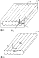
Figure 29 is a key diagram of making the process of birefringence cylinder;
Figure 30 is to make the process of its lens arra according to the birefringence cylinder of laterally arranging shown in Figure 29; And
Figure 31 is by fitting to the product figure that the first and the 3rd lens obtain according to the birefringence cylindrical lens of process manufacturing shown in Figure 30.
Embodiment
Describe embodiments of the present invention in detail below with reference to accompanying drawing.
(first embodiment)
The 3 D image display device of first embodiment of the invention is described below with reference to Fig. 1 to Figure 12.Fig. 1 is the horizontal sectional view according to the 3 D image display device of this embodiment.
3 D image display device according to this embodiment is provided with flat display apparatus (being also referred to as " two-dimensional display ") 2 and Beam Control unit 10.Flat display apparatus 2 is liquid crystal indicators; for example, it is equipped with the display part 3 that is used to show the image information with a plurality of pixels of arranging with matrix-style, and the protective substrate 4 that is used to protect display part 3; this protective substrate 4 is made of transparent element, for example glass.
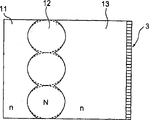
Beam Control unit 10 is set at the front (observer's 100 residing sides) of flat display apparatus 2, and is provided with lens arra 11, lens arra 12 and lens arra 13.Lens arra 11 comprises a plurality of monolateral concavees lens, and its each lens have flat shape in observer's 100 1 sides, and have the concavees lens shape in flat display apparatus 2 one sides.Each monolateral concave lens extends (with the direction of the drawing quadrature of Fig. 1) with vertical direction on the screen of flat display apparatus 2.Lens arra 13 is nearer from flat display apparatus 2 than lens arra 11, it comprises a plurality of monolateral concavees lens, each lens has flat shape in flat display apparatus 2 one sides, and having the concavees lens shape in observer's 100 1 sides, these lens are set to a plurality of monolateral concavees lens corresponding to lens arra 11.Each monolateral concave lens extends (with the direction of the drawing quadrature of Fig. 1) with vertical direction on the screen of flat display apparatus 2.The concavees lens shape of each the monolateral concave lens in the lens arra 11 and the concavees lens shape of each the monolateral concave lens in the lens arra 13 are roughly the same.Adopting a kind of like this arrangement to make the optical axis of the corresponding female lens in optical axis and the lens arra 13 of each the monolateral concave lens in the lens arra 11 be similar to each other overlaps.Be provided with lens arra 12 between lens arra 11 and the lens arra 13, lens arra 12 has a plurality of biconvex lens, and each lens has convex lens shape in observer's 100 1 sides, and also has convex lens shape in flat display apparatus 2 one sides.Each biconvex lens extends (with the direction of the drawing quadrature of Fig. 1) with vertical direction on the screen of flat display apparatus 2.The corresponding convex lens of the biconvex lens in the lens arra 12 form like this, make it can adapt between the concavees lens of lens arra 11 and lens arra 13.In this embodiment, lens arra 11 and lens arra 13 have roughly the same refractive index, but the refractive index of lens arra 12 is different with the refractive index of lens arra 11 and 13.
In Fig. 1, the optical axis of Reference numeral 40 each lens of expression, Reference numeral 42 expressions enter the ray trajectory of observer's 100 eyes.Reference numeral 3a represents the set of diagrams picture of lens of a correct unit image (distribute to (or corresponding to)) the position, Reference numeral 3b represents the position of the unit image of a mistake, Reference numeral 50 expression parasitic light zones.
Next will be noted that in this embodiment the condition that parasitic light and cross (talk) amount reduce in the 3 D image display device that constitutes in the above described manner.
Can obtain the focal length of biconvex lens with reference to figure 2.Fig. 2 shows the ray trajectory by the biconvex lens with two kinds of lens curved surfaces 24 and 25.Biconvex lens is that the medium 22 of N constitutes by refractive index, and refractive index is that the medium 21 of n is set at observer's 100 1 sides, is set at a side relative with observer 100 and refractive index is the medium 23 of n '.
In Fig. 2, u1, u2 and u3 represent to have respectively refractive index n, arrive the incident angle of optical axis 40 on the medium 21,22 and 23 of N and n '.Reference numeral H1 and H2 represent the principal point of object one side and the principal point of image one side.Reference numeral h1 and h2 represent when light 44 enters lens face 24 and enters lens face 25 height apart from optical axis 40.Reference numeral r1 and r2 represent the radius-of-curvature of lens face 24 and 25.Focal distance f represent when parallel rays among Fig. 2 when observer's 100 1 sides enter lens principal point and the distance between the focus, corresponding between this distance and image one side principal point H2 and the focus O apart from s '.Reference numeral d represents the distance between the thickest part of convex lens, or the lens thickness of biconvex lens.
Draw following relation by Fig. 2.
h2=h1-du
2
Can obtain following equation (1) by above-mentioned equation
By equation (1) as can be known, suppose that focal distance f fixes, between poor, the radius-of-curvature r1 of the refractive index between biconvex lens 22 and the medium 21,23 and r2 and lens thickness d, have certain relation.
In general, suppose fixed focal length, the less lens face of wherein a kind of medium and refractive index contacts, and the radius-of-curvature of lens curved surface diminishes, make lens protrusion and recessedly become big.In this case, oval by adopting as lens shape, can reduce deviation.Therefore, in view of this advantage, the difference of refractive index is set to a less value here, as 0.1, makes oval-shaped employing become simple.When between two dimensional image display mode and 3-D view display mode, switching, can obtain effectively in the difference of the refractive index relation between hour lens thickness and the radius-of-curvature, because the difference of the refractive index of common liquid crystals is less, be a value in 0.1 to 0.2 scope.
In equation (1), consider simple in the manufacturing, the radius-of-curvature r1 of biconvex lens and r2 are arranged to identical, and with the refractive index n of the refractive index n of the medium 21 of outermost (observer's 100 1 sides) and the medium 23 of the most inboard (side relative) ' be arranged to identical with observer 100.Under such setting, can obtain following equation (2) and (3) by equation (1).
In equation (3), because lens thickness d is the quadratic function of lens radius of curvature r, it has an extreme value.In fact, because the hypothesis lens curved surface is a sphere in the equation (3), when using ovally during as lens curved surface in order to reduce lens deviations, lens thickness d can not be correctly consistent with equation (3), but its trend roughly matches with equation (3).
Next, utilize the optical analogy device that lens shape is optimized for ellipse.Each embodiment in this embodiment is equipped with three kinds of lens 11 with same focal point usually, under 12 and 13 the situation, when the lens material with identical refractive index is used to lens 11 and 13 and radius-of-curvature r and lens thickness d when changing, to the explanation of planar lens shown in Fig. 3,4 and 5.In Fig. 3 to 5, the thickness of the part that biconvex lens is the thickest is expressed as d, and the distance table between the thinnest part of each lens of biconvex lens is shown ds, and the protrusion of each lens and recessed between difference be expressed as d1.
Fig. 3 is the view of an embodiment of lens, and radius-of-curvature r is set to maximal value here.In the embodiment shown in fig. 3, ds is big because d1 is little, and it is very big that integral thickness d becomes.In Fig. 3, can understand like this, because ds is very big, it is very wide or very big that parasitic light light zone 50 becomes.Fig. 4 is the view of an embodiment of lens, and radius-of-curvature r radius-of-curvature of lens in Fig. 3 reduces slightly here.In embodiment as shown in Figure 4, because reducing of radius-of-curvature r makes the ability of bending of light become big at lens surface.Therefore, in embodiment as shown in Figure 4, ds diminishes and integral thickness d also diminishes.In embodiment as shown in Figure 4, can recognize that because ds reduces, parasitic light zone 50 also narrows down or diminishes.At last, Fig. 5 is the view of an embodiment of lens, and radius-of-curvature r is set to minimum value here.In embodiment as shown in Figure 5, ds becomes minimum because d1 becomes big, and it is big that integral thickness d becomes once more.Therefore, in embodiment as shown in Figure 5, we can say does not almost have parasitic light zone 50.
D, ds that obtains according to the optimization of lens shape and the relation between the r are as shown in Figure 6.In Fig. 6, the value of common plastics lens is used as refractive index n and N, and establish refractive index difference Δ n (=N-n)=0.1.As can be seen from Figure 6, the thickness d of biconvex lens and ds become big (thickening) based on the increase of radius-of-curvature r.
From the above description as can be seen, very narrow in order to make parasitic light zone 50, must reduce ds.Therefore, in this embodiment, parasitic light zone 50 is 10% or lower with the ratio of unit image-region, and this condition will be illustrated as a target.
In Fig. 7, visual angle in 3 D image display device is under the situation of 2 θ, and the refractive index that is expressed as the most close observer's 100 concavees lens 11 among Ip and Fig. 7 when the lens distance is expressed as n, and parasitic light zone 50 is shown m with the ratiometer of unit image, can obtain equation (4), (5) and (6).
sinθ=nsinθ′ (4)
m=ds×sinθ′/I
p<0.1 (5)
m=ds×sinθ/(I
p×n)<0.1 (6)
Subsidiary, in Fig. 7, because protective substrate 4 shown in Figure 1 has and lens 13 refractive index much at one, it is included in the lens 13.Represented as equation (2), for the dome shape lens, if determined lens thickness d, radius-of-curvature r and lens just can obtain ds apart from Ip.The formation of lens shape can be satisfied equation (6).When being dome shape and ellipticity, satisfy by lens equation (4) to (6).Subsidiary, Figure 8 shows that lens are elliptoid embodiment.In Fig. 8, biconvex lens 12 represents with solid line that for elliptoid situation biconvex lens 12 is represented for the situation with dashed lines of dome shape.
When the value of ds is 0 μ m, when 0.187 μ m and 0.414 μ m, the correlativity of the ratio m of visual angle and parasitic light zone and unit image as shown in Figure 9.As can see from Figure 9, when the value of ds is 0.187 μ m or more hour, the ratio m of parasitic light zone 50 in the visual angle is 45 ° or littler scope can be reduced to 10% or littler.
When the scioptics simulator had been realized optimization, the correlativity θ of the cross (talk) amount of visual angle and resulting monolateral lens and biconvex lens as shown in figure 10.Here, the cross (talk) amount is meant when light and utilizes pixel wide (sub pixel width) to be gathered range criterionization on the two-dimensional display by lens.Because view angle theta is to leave the angle of the straight line of normal to screen, is represented by 2 θ by the overall viewing angle that the visual angle, left side and the visual angle, right side of vertical line are formed.In Figure 10, for example, refer among the figure three Pixel Information unit are mixed in the parallax light with special angle, at this moment the cross (talk) amount is 3.The increase of cross (talk) amount causes display quality to reduce, and shows burr or ghost image as 3-D view.
Can recognize that from Figure 10 (under=N-n)=0.1 situation, because the defective of lens power, the cross (talk) amount increases to 4 or bigger to the difference Δ n of refractive index in monolateral lens.(under=N-n)=0.19 situation, lens power increases the difference Δ n of refractive index in monolateral lens, but the cross (talk) amount is very big, and as 2 or bigger, the visual angle is that 0 o'clock cross (talk) amount is 3.Therefore, as if because the visual angle is that 0 o'clock cross (talk) amount is very big, image degradation is more obvious.The difference Δ n of refractive index in biconvex lens is (under=N-n)=0.1 situation, because the cross (talk) amount is 30 ° or more hour is suppressed to 2 that in view angle theta the deterioration that 3-D view shows is very little.Subsidiary, the embodiment of monolateral lens as shown in figure 11, the embodiment of biconvex lens is as shown in figure 12.In Figure 11, the monolateral convex lens of Reference numeral 14 expressions.In Figure 11 and 12, the track of the parallel rays of Reference numeral 46 expressions when the light along optical axis enters each lens.
As mentioned above, according to this embodiment, even the visual angle is very wide or very big, cross (talk) amount and parasitic light also can reduce.
Next be noted that the method for making lens arra 11,12 and 13 according to this embodiment.
In one approach, by a biconvex lens that the plane centered on can be by making three kinds of lens arras 11,12 and 13 mould and make three kinds of plastic lenss and make so that they are made up.
In another approach, used silicon rubber.In the method, have only the lens arra 12 usefulness plastics at center to make with very high precision according to reservation shape, the lens arra 13 of the lens arra 11 of observer's 100 1 sides and two-dimensional display 2 one sides utilizes silicon rubber mold formed, rather than with the whole lens of plastics manufacturing.In this method, lens arra 11,12 and 13 can be combined and at an easy rate without any the slit.Used herein is transparent silicon rubber.When lens arra 11 and 13 usefulness silicon rubber are mold formed, use bilingual section bar material as far as possible, and silicon rubber is cured at one on than the lower temperature of the allowable temperature limit of center plastic lens 12.
Illustrate according to the lens arra 11,12 of this embodiment and another specific embodiment of 13 below with reference to Figure 13.In specific embodiment shown in Figure 13, in three kinds of lens arras 11,12 and 13, the lens arra 13 that is arranged on the lens arra 11 of observer's 100 1 sides and is arranged on two-dimensional display one side is made of plastic lens, and center lens array 12 constitutes by the material of filling liquid for example etc. and can freely change shape, thereby produces compound lens.In the biconvex lens that forms like this, the parasitic light zone can be by making the consistent each other minimum value that is reduced to of each lens.Therefore, location for convenience is provided with recessed and protrusion at the part 12a place of the lens 13 of convex lens 11 that connect observer's one side and two-dimensional display one side.By providing recessed by this way and protruding, having high-precision location can be achieved based on self calibration.
(second embodiment)
Next, will be with reference to figs. 14 to the 3 D image display device of 23 explanations according to second embodiment of the invention.Figure 14 is the horizontal sectional view according to the 3 D image display device of this embodiment.
3 D image display device according to this embodiment is provided with flat display apparatus (being also referred to as " two-dimensional display ") 2 and Beam Control unit 10.Flat display apparatus 2 is liquid crystal indicators; for example, it is equipped with the display part 3 that is used to show the image information with a plurality of pixels of arranging with matrix-style, and the protective substrate 4 that is used to protect display part 3; this protective substrate 4 is made of transparent element, for example glass.
Beam Control unit 10 is set at the front of flat display apparatus 2, and it is provided with lens arra 15,16, transparency carrier 17 and lens arra 18,19, and they are pressed said sequence from observer's one side and arrange.Lens arra 15 has a plurality of monolateral concavees lens, and wherein each lens has flat shape in observer's one side, and has the concavees lens shape in flat display apparatus 2 one sides.Each monolateral concave lens extends (with the direction of the drawing quadrature of Figure 14) with vertical direction on the screen of flat display apparatus 2.Lens arra 19 is set at from the nearest position of flat display apparatus 2 one sides, and it comprises a plurality of monolateral concavees lens, and each monolateral concave lens has flat shape in flat display apparatus 2 one sides, and has the concavees lens shape in observer's one side.They are set to a plurality of monolateral concavees lens corresponding to lens arra 15.Each monolateral concave lens extends (with the direction of the drawing quadrature of Figure 14) with vertical direction on the screen of flat display apparatus 2.The concavees lens shape of each monolateral concave lens is roughly the same in monolateral concavees lens shape of in the lens arra 15 each and the lens arra 19.Adopt a kind of like this optical axis 40 of arranging the monolateral lens in the feasible lens arra 15 and 19 that corresponds to each other almost to overlap each other.Transparency carrier 17 is to be made of the transparent element that all has flat shape in observer's one side and flat-panel screens one side, and its width is ds, and is set between lens arra 15 and the lens arra 19, thereby contacts with lens arra 16 and lens arra 18.Lens arra 16 is made of the material that can freely change shape, for example liquid or liquid crystal, and it is filled between the plane of the recessed portion of monolateral concavees lens of lens arra 15 and transparency carrier 17.Lens arra 18 is made of the material that can freely change shape, for example liquid or liquid crystal, and it is filled between another plane of the recessed portion of monolateral concavees lens of lens arra 19 and transparency carrier 17.The material that constitutes lens arra 16 and lens arra 18 has higher refractive index than the material that constitutes lens arra 15 and 19.
In this embodiment, the examples of material that is used as lens arra 16 and 18 as the birefringent material of liquid crystal and so on will describe following.Liquid crystal is injected in the gap between the glass substrate of the thickness that has several microns usually or size, and aligns according to orientation film in the two ends of liquid crystal molecule.Liquid crystal molecule makes liquid crystal molecule can align in the order that keeps whole liquid crystal in the maintenance orientation at the interface of joining with glass substrate.Three problems have appearred here.
When the thickness between the glass substrate (hereinafter referred to as " gap ") when increasing to the hundreds of micron, only on the interface between liquid crystal and the glass substrate, could obtain directedly, and whole liquid crystal is directed chaotic, thereby fluctuation in the face of refractive index occurs.It is necessary accurately controlling two distances between the convex lens in view of optical characteristics.When make outer concavees lens 15 and interior concavees lens 19 and liquid crystal is filled into therebetween core or the gap in the time, core in the structure as shown in Figure 1 or the liquid crystal generation free deformation in the gap are very difficult thereby make the suitable whole lens in gap.
Therefore, as shown in figure 14, can access following three advantages by between convex lens, placing transparency carrier 17:
(1) can contact with transparency carrier 17 by protrusion place the gap is controlled concavees lens 15 and 19.
(2) by on thin transparency carrier 17, making the orientation film of liquid crystal, the gap can be set at lens thickness half or littler, this just makes Liquid Crystal Molecules Alignment is become easy on identical or same direction.
(3) because thin transparency carrier 17 does not have curved surface, also do not have lens effect, the refractive index of transparency carrier 17 can be selected arbitrarily.Therefore, the orientation film process stabilizing, and can use hard glass substrate with the absorption coerfficient that reduces and planar-formed easily.But can dependability difference cheap plastic film, and have improved degree of freedom.
In above-mentioned the 3rd, the result by the cross (talk) amount gained in the different refractivity of Simulation Center transparency carrier 17 as shown in figure 15.Figure 15 show when the refractive index of transparency carrier 17 be included in concavees lens 15 and 19 in lens arra 16 and the refractive index of lens arra 18 resulting lens analog result when just in time equating, and when the lens analog result of using (particularly, using glass substrate) gained when having different refractive index materials.As can be seen from Figure 15, two kinds of situation difference are little, and the two is too not different each other on the 3-D view display performance.
As mentioned above, according to this embodiment, when adopting big or wide visual angle, cross (talk) amount and parasitic light reduce.
Next will be noted that the modification of being convenient to the embodiment that the lens to observer's one side and two-dimensional display one side position.
What at first will describe is the method that the optical axis 40 of the concavees lens 19 of the concavees lens 15 of observer's one side and two-dimensional display one side is overlapped each other, wherein clips thin transparency carrier 17 between concavees lens 15 and concavees lens 19.In one approach, telltale mark is added between lens 15,19 and the lens substrate 17, and concavees lens 15 and 19 are engaged to the both sides of transparency carrier 17, make that like this lens 15,19 and transparency carrier 17 are consistent each other.In the method, because lens material is not the depression that is positioned at concavees lens 15 and 19, can not realize the location with image.So, as shown in figure 16, can adopt a kind of like this structure,, and make respectively by in conjunction with the concavees lens 15 of observer's one side and the resulting element of transparency carrier 17a and by in conjunction with concavees lens 19 and the resulting element of transparency carrier 17b as transparency carrier with two thin transparency carrier 17a and 17b.Manufacture method in this case will be illustrated below.
What at first will finish is the step that concavees lens 15 and transparency carrier 17a with observer's one side mutually combine, and injects the step of liquid crystal and the step of encapsulated liquid crystals.What next will finish is the step that the concavees lens on the two-dimensional display 19 and transparency carrier 17b are mutually combined, and injects the step of liquid crystal and the step of encapsulated liquid crystals.At this moment, the lens liquid crystal of observer's one side two-dimensional display one side is placed in directed state.Therefore, when observation test pattern under the 3-D view display mode, can carry out accurate localization.
Because the thickness of the concavees lens 15 of observer's one side has nothing to do with focal length,, require concavees lens 15 must have intensity to a certain degree and should do thinlyyer in order to reduce the thermal deformation of lens.The thickness of the concavees lens 19 on the two-dimensional display must be complementary with focal length.Therefore, the lens 15 of observer's one side have this situation of different thickness with lens 19 on the two-dimensional display and often take place.Owing to must make two kinds of lens in this case, cause production cost to increase.3-D view shows that a possible reason that worsens is the difference owing to the thermal deformation between two kinds of lens.Therefore, as shown in figure 17, be set to have identical thickness with lens on the two-dimensional display and utilize glass substrate 5 to adjust these thickness, can reduce production costs and improve reliability by observer's one side.
Next will be noted that the condition of the index of refraction in lens when the conversion between realization two dimensional image and the 3-D view.When the refractive index that is expressed as ne and short-axis direction when the refractive index of long axis direction is no, there is the non-vanishing liquid crystal of poor (ne-no)=Δ n of many its refractive indexes.For example, when the difference Δ n that uses refractive index is positive liquid crystal, light can not be converged on the 3 d image display, unless the refractive index N of the liquid crystal lens in the structure shown in Figure 14,16 or 17 is greater than the refractive index n of the concavees lens on observer's one side or the two-dimensional display.Therefore, must change plane of polarization under the 3-D view display mode makes the bigger refractive index n e of liquid crystal increase.
Then, need change plane of polarization under the two dimensional image display mode makes the less refractive index n o of liquid crystal increase.Here, when the refractive index n of the concavees lens on observer's one side and the two-dimensional display and no are basic identical, can realize a high-quality two dimensional image display mode, and can not cause convergence of rays.To achieve these goals, wish that the frictional direction of orientation film can be parallel with the line of centres of concavees lens.
As mentioned above, below will be noted that liquid crystal polarized variation between 3-D view display mode and the two dimensional image display mode.
The unit that changes plane of polarization is divided into two kinds of situations roughly, a kind of be each unit be set at two-dimensional display 2 and the Beam Control unit 10 that constitutes by compound lens between, another kind of situation is that it is set between Beam Control unit 10 and observer's one side.
For example, be used for plane of polarization is changed 90 ° a example of unit shown in Figure 18 and 19.In Figure 18 and 19, determine frictional direction 65, make the mutual half-twist of the directed face angle of glass substrate 63a and 63b, thereby realized friction.Figure 18 shows voltage controller 66 of no use and apply voltage condition between glass substrate 63a and 63b, and wherein plane of polarization is rotated 90 ° of angles.Figure 19 shows with voltage controller 66 and apply voltage condition between glass substrate 63a and 63b, wherein liquid crystal 64 become vertical with glass substrate 63a with 63b, thereby plane of polarization is not rotated.
Figure 20 and 21 show that the unit 60 that is used to control plane of polarization is set at two-dimensional display 2 and the Beam Control unit 10 that constitutes by compound lens between situation.Figure 20 shows that the 3-D view display mode.For example, when the plane of polarization 62 of liquid crystal indicator 2 is set to parallel with the long axis direction Ne of liquid crystal molecule and plane of polarization 62 when not being rotated 90 °, when promptly using state as shown in figure 19, plane of polarization 62 becomes parallel, thereby three bit image display modes are improved.
Shown in Figure 21 is the two dimensional image display mode.When plane of polarization 62 was rotated 90 ° of angles, promptly when using state shown in Figure 180, the refractive index No that plane of polarization 62 becomes on the short-axis direction with liquid crystal molecule was parallel, thereby the two dimensional image display mode is improved.When the unit 60 that is used to control plane of polarization be set at two-dimensional display 2 and the Beam Control unit 10 that constitutes by compound lens between the time, need make the distance between the pixel faces of compound lens face and two-dimensional display 2 consistent with focal length.Therefore, the glass substrate that clips liquid crystal 64 shown in Figure 18 and 19 must utilize polished glass substrate or the similar processes must be thinner.
Figure 22 and 23 shows the unit 60 that is used to control plane of polarization and is set at the Beam Control unit 10 that is made of compound lens and the situation between observer's 100 1 sides.Shown in Figure 22 is the 3-D view display mode, and wherein the plane of polarization 62 of two-dimensional display 2 is rotated mutually at long axis direction Ne and short-axis direction No on 45 ° the direction and aligns.In addition, the image with same brightness passes through the long axis direction Ne and the short-axis direction No both direction of liquid crystal molecule owing to the Beam Control unit 10 that is made of compound lens.Shown in Figure 23 is three bit image display modes.In this case, because plane of polarization 62 is rotated 90 ° of angles, by top side polarization plates 61, the observer can only observe the light of long axis of liquid crystal molecule direction Ne.In the two dimensional image display mode, polarization plates 62 is not subjected to 90 ° rotation.Have only the plane of polarization 62 of the light permission parallel through the top side with the short-axis direction No of liquid crystal molecule.
Because plane of polarization can change by the mode of these means with electricity, make between two dimensional image display mode and the three bit image display modes instantaneous switching and be converted into possibility.
In this embodiment, the center lens in the Beam Control unit was described by the situation that biconvex lens constitutes.Yet, when the center lens are made of biconcave lens, can access the 3-D view demonstration by in biconcave lens, filling the littler material of refractive index that has than the material that centers on it.
In first and second embodiments, the situation that is used as two-dimensional display 2 for liquid crystal indicator is illustrated.But flat display apparatus as OLED display or FED (Field Emission Display), can be used as two-dimensional display 2.
In first and second embodiments, the cylindrical lens sheet is used as Beam Control unit 10.Owing to can not occur anyly can seeing the relevant light shield part in position of image, and can access a continuous images, so the cylindrical lens sheet is more effective in 3 D image display device with the observer.
In first and second embodiments, the cylindrical lens that constitutes Beam Control unit 10 is arranged with vertical direction on the screen of two-dimensional display 2, but in order to prevent ripple, also can oblique arrangement.
In addition, the expression value of optimum position of the degree of depth of relevant two dimensional image has been shown in first and second embodiments, and near this expression value, also can have seen the two dimensional image that the image display performance does not worsen.
In aforesaid 3 D image display device, the switching between two dimensional image display mode and the 3-D view display mode can realize in the leveled time of a reality.
What below will describe is the manufacture method of the 3 D image display device of first embodiment of the invention.Polycarbonate film or arton film are known phase difference film.By these films are extended upward in certain party, on these thin film planars, can obtain birefringence.These films mainly are used to eliminate differing of liquid crystal cells, realize white and black displays thereby reduce color.Some phase difference film have uniaxial orientation nx in the indicatrix structure〉ny=nz.In birefringent characteristic, as the different characteristic nx of refractive index〉when ny was used in the plane, the image transitions between the two and three dimensions can be in conjunction with realizing as Figure 20, Figure 21, Figure 22 and structure shown in Figure 23.At this moment, in structure as shown in Figure 1, be under the situation of n in the refractive index of first lens and the 3rd lens, utilize the birefringence of second lens, make and satisfy nx in second lens n and ny=n.
For example, because polycarbonate film has the characteristic of nx=1.585 and ny=1.479, the difference Δ n of refractive index becomes 0.106, and the difference of the refractive index between birefringent each refractive index of this value and above-mentioned liquid crystal is basic identical.
Here can expect three kinds of manufacture methods.The birefringent film 20 that wherein provides thickness to equate with the maximum ga(u)ge of lens.As shown in figure 25, provide to be the set mould of lens 21, thereby and birefringent film 20 be configured as lensing by clamping films on applying pressure to film.At this moment, the realization of setting makes the nx with high index of refraction become parallel with the lens cylinder.Shown in Figure 26 is the birefringent lens of realizing after the punching press lens.Shown in Figure 27 is the example that uses first embodiment of birefringent lens shown in Figure 26.Utilize mould shown in Figure 27 can produce first lens 11 and the 3rd lens 13, and they are adjusted to the protrusion of birefringent lens shown in Figure 26 20 and recessedly are complementary.At this moment, first lens and the 3rd lens do not have birefringence, but are substantially equal to the first and the 3rd lens of the ny among Figure 26 by the selective refraction rate, and the may command polarization direction is to realize the conversion between the two and three dimensions.The first and the 3rd lens can be separately as the plastic lens manufacturing, and can make simply by punching press silicon rubber.
Because birefringent film is made by extending, so be difficult to produce very thick film.Described below is applied method in the time can not producing thick birefringent film.As shown in figure 28, monolateral convex lens utilize lens die to be created by birefringent material 20.Similarly, can produce and have identical shaped monolateral convex lens.Biconvex lens creates by engaging two monolateral convex lens in its planar side.In order to utilize method shown in Figure 28 to make biconvex lens, must monolateral convex lens be located mutually with very high precision.
Described below is the another kind of method of making birefringent lens.The material that has the transparency material of birefringent characteristic when extending at first must be provided.By extend cylindrical transparent material 22 on the cylinder short transverse, cylindrical transparent material 22 as shown in figure 29 can be configured as the cylindrical lens of the birefringent characteristic with expectation, shown in cylinder 23.As shown in figure 30, can produce second lens arra by the cylindrical lens that is arranged in parallel according to first embodiment.As shown in figure 31, make lens shown in first embodiment by between first lens 11 and the 3rd lens 13, clipping second lens arra.
Claims (14)
1. 3 D image display device comprises:
Flat display apparatus, it has the display plane that comprises a plurality of pixels of arranging with matrix-style; With
The Beam Control unit, it is set at the light of the positive and control of flat display apparatus from pixel, and this Beam Control unit comprises:
First lens arra with a plurality of lens, each lens be on the surface that observer's one side has flat shape, and have concave surface in flat display apparatus one side;
Second lens arra with a plurality of lens, each lens be on the surface that flat display apparatus one side has flat shape, and have spill size concave surface about equally with first lens arra in observer's one side, and
Be set between first lens arra and second lens arra and have the 3rd lens arra of a plurality of lens, each lens first lens arra, one side have with first lens arra in the matched convex surface of spill, and second lens arra, one side have with second lens arra in the matched convex surface of spill, wherein the convex of each lens in the 3rd lens arra of first lens arra, one side is corresponding with the convex of each lens in the 3rd lens arra of second lens arra, one side, wherein
The 3rd lens arra is configured to make that its each lens in first lens arra, one side are consistent with its corresponding lens in second lens arra, one side,
The refractive index of first and second lens arras is roughly the same, and the refractive index of the 3rd lens arra is different with the refractive index of first and second lens arras, and
The refractive index of first and second lens arras (n), the relation between the radius-of-curvature (r) of refractive index of the 3rd lens arra (N) and the 3rd lens arra, focal length (f) and the lens thickness (d) is represented by following equation:
2. according to the 3 D image display device of claim 1, wherein each in first and second lens arras has a plurality of monolateral concavees lens, and the 3rd lens arra has a plurality of biconvex lens.
3. according to the 3 D image display device of claim 2, wherein, the minimum lens thickness of each biconvex lens in the 3rd lens arra is expressed as ds, the visual angle is expressed as 2 θ, lens are apart from being expressed as Ip, and the refractive index of first lens arra is expressed as n, and then biconvex lens satisfies and to concern ds * sin θ/(Ip * n)<0.1.
4. according to the 3 D image display device of claim 2, wherein the 3rd lens arra is made of the material that freely changes shape.
5. according to the 3 D image display device of claim 2, wherein the 3rd lens arra is made of transparent solid material, and first and second lens arras form by utilizing silicones to stamp out the protrusion of the 3rd lens arra and be recessed into.
6. 3 D image display device comprises:
Flat display apparatus, it has the display plane that comprises a plurality of pixels of arranging with matrix-style; With
The Beam Control unit, it is set at the light of the positive and control of flat display apparatus from pixel, and this Beam Control unit comprises:
First lens arra with a plurality of monolateral concavees lens, each lens be on the surface that observer's one side has flat shape, and have concave surface in flat display apparatus one side;
Second lens arra with a plurality of monolateral concavees lens, each lens be on the surface that flat display apparatus one side has flat shape, and have spill size concave surface about equally with first lens arra in observer's one side,
Be set at the transparency carrier between first lens arra and second lens arra,
Be set between first lens arra and the transparency carrier and have the 3rd lens arra of a plurality of monolateral convex lens, each lens has and the matched convex surface of the spill of first lens arra in first lens arra, one side, and on the surface that transparency carrier one side has flat shape, and
Be set between the transparency carrier and second lens arra and have the 4th lens arra of a plurality of monolateral convex lens, each lens second lens arra, one side have with the spill fit of second lens arra and with the corresponding convex surface of the convex of the 3rd lens arra, and on the surface that transparency carrier one side has flat shape, wherein
The monolateral convex lens of each of the 3rd lens arra are constructed to make its optical axis to overlap with the corresponding monolateral convex lens of the 4th lens arra,
The refractive index of first and second lens arras is roughly the same, the refractive index height of refractive index ratio first and second lens arras of third and fourth lens arra, and
The refractive index of first and second lens arras (n), the relation between the radius-of-curvature (r) of the refractive index of third and fourth lens arra (N) and third and fourth lens arra, focal length (f) and the lens thickness (d) is represented by following equation:
7. Beam Control unit comprises:
Have first lens arra of a plurality of lens, each lens has the surface of flat shape in a side, and has concave surface at opposite side;
Second lens arra with a plurality of lens, each lens be on the surface that a side has flat shape, and opposite side have with the spill of first lens arra about equally concave surface and
Be arranged between first lens array and second lens arra and have the 3rd lens arra of a plurality of lens; Each lens first lens array one side have with the first lens array in the convex surface of spill fit; And second lens arra, one side have with second lens arra in the convex surface of spill fit; Wherein the convex of each lens in the 3rd lens arra of first lens array one side is corresponding with the convex of each lens in the 3rd lens arra of second lens arra, one side
Wherein the refractive index of first and second lens arras is roughly the same, and the refractive index of the 3rd lens arra is different with the refractive index of first and second lens arras, and
The refractive index of first and second lens arras (n), the relation between the radius-of-curvature (r) of refractive index of the 3rd lens arra (N) and the 3rd lens arra, focal length (f) and the lens thickness (d) is represented by following equation:
8. according to the Beam Control unit of claim 7, wherein the 3rd lens arra is configured to arrange cylindrical lens and makes that the longitudinal axis of cylindrical lens is parallel.
9. Beam Control unit according to Claim 8, wherein each cylindrical lens has birefraction, and wherein the refractive index of y direction is different with the refractive index of X direction.
10. according to the Beam Control unit of claim 9, wherein one of refractive index of the refractive index of X direction and first and second lens arras equates.
11. a Beam Control unit comprises:
Have first lens arra of a plurality of monolateral concavees lens, each lens has the surface of flat shape in a side, and has concave surface at opposite side;
Second lens arra with a plurality of monolateral concavees lens, each lens be on the surface that a side has flat shape, and have spill size concave surface about equally with first lens arra at opposite side,
Be set at the transparency carrier between first lens arra and second lens arra,
Be set between first lens arra and the transparency carrier and have the 3rd lens arra of a plurality of monolateral convex lens, each lens has and the matched convex surface of the spill of first lens arra in first lens arra, one side, and on the surface that transparency carrier one side has flat shape, and
Be set between the transparency carrier and second lens arra and have the 4th lens arra of a plurality of monolateral convex lens, each lens second lens arra, one side have with the spill fit of second lens arra and with the corresponding convex surface of the convex of the 3rd lens arra, and on the surface that transparency carrier one side has flat shape
Wherein the refractive index of first and second lens arras is roughly the same, and the refractive index height of refractive index ratio first and second lens arras of third and fourth lens arra, and
The refractive index of first and second lens arras (n), the radius-of-curvature (r) of the refractive index of third and fourth lens arra (N) and third and fourth lens arra, the relation between focal length (f) and the lens thickness (d) is represented by following equation:
12. according to the Beam Control unit of claim 11, wherein the 3rd lens arra is configured to arrange cylindrical lens and makes that the longitudinal axis of cylindrical lens is parallel.
13. according to the Beam Control unit of claim 12, wherein each cylindrical lens has birefraction, wherein the refractive index of y direction is different with the refractive index of X direction.
14. according to the Beam Control unit of claim 13, wherein one of refractive index of the refractive index of X direction and first and second lens arras equates.
Applications Claiming Priority (2)
| Application Number | Priority Date | Filing Date | Title |
|---|---|---|---|
| JP2005095607A JP4334495B2 (en) | 2005-03-29 | 2005-03-29 | Stereoscopic image display device |
| JP2005095607 | 2005-03-29 |
Publications (2)
| Publication Number | Publication Date |
|---|---|
| CN1841129A CN1841129A (en) | 2006-10-04 |
| CN100485450C true CN100485450C (en) | 2009-05-06 |
Family
ID=37030220
Family Applications (1)
| Application Number | Title | Priority Date | Filing Date |
|---|---|---|---|
| CNB2006100683390A Expired - Fee Related CN100485450C (en) | 2005-03-29 | 2006-03-29 | Stereo image display equipment |
Country Status (3)
| Country | Link |
|---|---|
| US (1) | US20060256259A1 (en) |
| JP (1) | JP4334495B2 (en) |
| CN (1) | CN100485450C (en) |
Families Citing this family (29)
| Publication number | Priority date | Publication date | Assignee | Title |
|---|---|---|---|---|
| JP4421507B2 (en) * | 2005-03-30 | 2010-02-24 | 株式会社東芝 | Sleepiness prediction apparatus and program thereof |
| JP2008176167A (en) * | 2007-01-22 | 2008-07-31 | Seiko Epson Corp | Method for manufacturing electro-optical device |
| KR101352115B1 (en) * | 2007-03-07 | 2014-01-24 | 엘지디스플레이 주식회사 | Optical sheet for three-dimensional image and three-dimensional image display device using the same |
| JP5105920B2 (en) * | 2007-03-20 | 2012-12-26 | 株式会社東芝 | Stereoscopic image display device |
| JP5022964B2 (en) | 2008-03-28 | 2012-09-12 | 株式会社東芝 | 3D image display apparatus and 3D image display method |
| WO2009136582A1 (en) * | 2008-05-07 | 2009-11-12 | Nagashima Michiyoshi | Image display article |
| US8552925B2 (en) | 2008-09-24 | 2013-10-08 | Kabushiki Kaisha Toshiba | Stereoscopic image display apparatus |
| JP5498676B2 (en) * | 2008-09-24 | 2014-05-21 | 株式会社東芝 | Stereoscopic image display device |
| JP2010224191A (en) * | 2009-03-23 | 2010-10-07 | Toshiba Corp | Apparatus for displaying stereoscopic image |
| TWI408331B (en) * | 2009-12-17 | 2013-09-11 | Ind Tech Res Inst | Measurement device and method of double-sided optical films |
| JP2010122701A (en) * | 2010-01-08 | 2010-06-03 | Panasonic Corp | Three-dimensional image reproducing device |
| US10294672B2 (en) * | 2010-04-26 | 2019-05-21 | Guardian Glass, LLC | Multifunctional photovoltaic skylight with dynamic solar heat gain coefficient and/or methods of making the same |
| JP5699609B2 (en) | 2011-01-06 | 2015-04-15 | ソニー株式会社 | Image processing apparatus and image processing method |
| GB2488979A (en) * | 2011-03-07 | 2012-09-19 | Sharp Kk | Switchable Optics with GRIN lenses formed in liquid crystal layer |
| JP5716465B2 (en) * | 2011-03-09 | 2015-05-13 | ソニー株式会社 | Imaging device |
| JP5832843B2 (en) * | 2011-10-04 | 2015-12-16 | 日立マクセル株式会社 | Autostereoscopic display |
| CN102445762B (en) * | 2012-01-06 | 2013-07-10 | 清华大学深圳研究生院 | Naked eye 3D (three-dimensional) projection screen and naked eye 3D projection system |
| CN202443141U (en) * | 2012-02-23 | 2012-09-19 | 京东方科技集团股份有限公司 | Color filter substrate and 3D display device |
| CN103365021B (en) * | 2012-04-03 | 2015-11-25 | 元太科技工业股份有限公司 | Electrophoretic display device capable of switching between color mode and black-and-white mode |
| JP2013246407A (en) * | 2012-05-29 | 2013-12-09 | Dainippon Printing Co Ltd | Optical sheet and display device |
| JP5994544B2 (en) * | 2012-10-03 | 2016-09-21 | 大日本印刷株式会社 | Optical sheet, display device, and optical sheet manufacturing method |
| CN104730722A (en) * | 2013-12-18 | 2015-06-24 | 财团法人工业技术研究院 | Time multitask scanning device and 3D display device |
| EP2887123A1 (en) * | 2013-12-18 | 2015-06-24 | Thomson Licensing | Optical see-through glass type display device and corresponding optical element |
| CN105700164B (en) * | 2016-04-12 | 2018-05-11 | 武汉华星光电技术有限公司 | A kind of 3D display module and 3D display device |
| JP6859655B2 (en) * | 2016-10-12 | 2021-04-14 | 大日本印刷株式会社 | Display device |
| KR102470569B1 (en) * | 2017-12-29 | 2022-11-24 | 엘지디스플레이 주식회사 | Transparent Display Appartus |
| NL2022328B1 (en) * | 2018-12-30 | 2020-07-23 | Zhangjiagang Kangde Xin Optronics Mat Co Ltd | Lenticular lens with a gradient |
| CN115128828A (en) * | 2021-03-26 | 2022-09-30 | 宏碁股份有限公司 | Stereoscopic display device |
| CN113885222A (en) * | 2021-10-13 | 2022-01-04 | 伟时电子股份有限公司 | Air suspension type display device |
Citations (3)
| Publication number | Priority date | Publication date | Assignee | Title |
|---|---|---|---|---|
| US5392140A (en) * | 1992-05-15 | 1995-02-21 | Sharp Kabushiki Kaisha | Optical device with two lens arrays with the second array pitch an integral multiple of the first array pitch |
| CN1361881A (en) * | 1999-06-18 | 2002-07-31 | 3M创新有限公司 | Projection screen with lenticular lenses of different optical power |
| CN1188727C (en) * | 1995-06-07 | 2005-02-09 | 雅各布·N·沃斯塔德特 | Three-dimensional imaging system |
Family Cites Families (7)
| Publication number | Priority date | Publication date | Assignee | Title |
|---|---|---|---|---|
| US4709996A (en) * | 1982-09-30 | 1987-12-01 | Michelson Paul E | Fluid lens |
| GB8716369D0 (en) * | 1987-07-10 | 1987-08-19 | Travis A R L | Three-dimensional display device |
| US6734838B1 (en) * | 1998-05-18 | 2004-05-11 | Dimension Technologies Inc. | Enhanced resolution for image generation |
| JP2002214405A (en) * | 2001-01-22 | 2002-07-31 | Omron Corp | Lens array substrate and image display device |
| US6894840B2 (en) * | 2002-05-13 | 2005-05-17 | Sony Corporation | Production method of microlens array, liquid crystal display device and production method thereof, and projector |
| KR100993240B1 (en) * | 2003-02-05 | 2010-11-10 | 에이유 오프트로닉스 코퍼레이션 | Switchable display apparatus |
| KR100540109B1 (en) * | 2003-02-06 | 2006-01-10 | 가부시끼가이샤 도시바 | Stereoscopic image display apparatus |
-
2005
- 2005-03-29 JP JP2005095607A patent/JP4334495B2/en not_active Expired - Fee Related
-
2006
- 2006-03-17 US US11/377,437 patent/US20060256259A1/en not_active Abandoned
- 2006-03-29 CN CNB2006100683390A patent/CN100485450C/en not_active Expired - Fee Related
Patent Citations (3)
| Publication number | Priority date | Publication date | Assignee | Title |
|---|---|---|---|---|
| US5392140A (en) * | 1992-05-15 | 1995-02-21 | Sharp Kabushiki Kaisha | Optical device with two lens arrays with the second array pitch an integral multiple of the first array pitch |
| CN1188727C (en) * | 1995-06-07 | 2005-02-09 | 雅各布·N·沃斯塔德特 | Three-dimensional imaging system |
| CN1361881A (en) * | 1999-06-18 | 2002-07-31 | 3M创新有限公司 | Projection screen with lenticular lenses of different optical power |
Also Published As
| Publication number | Publication date |
|---|---|
| JP4334495B2 (en) | 2009-09-30 |
| CN1841129A (en) | 2006-10-04 |
| JP2006276466A (en) | 2006-10-12 |
| US20060256259A1 (en) | 2006-11-16 |
Similar Documents
| Publication | Publication Date | Title |
|---|---|---|
| CN100485450C (en) | Stereo image display equipment | |
| CN102162964B (en) | Liquid crystal lens and display device | |
| KR101472052B1 (en) | Display device | |
| CN100434970C (en) | Display device | |
| KR101128519B1 (en) | High resolution autostereoscopic display | |
| CN102077601B (en) | Autostereoscopic display device | |
| CN102073142B (en) | Stereoscopic display unit | |
| US9104034B2 (en) | Display apparatus | |
| CN100419500C (en) | 2D/3D switchable display | |
| CN102231020B (en) | Novel three-dimensional display system | |
| CN102778756B (en) | Image display device | |
| CN102096229B (en) | 2D/3D (two-dimensional/three-dimensional) switching type stereoscopic display and control method thereof | |
| CN101261369A (en) | Convertible automatic stereo display device | |
| CN104204926A (en) | Display with observer tracking | |
| CN102636930B (en) | Adopt the 3D display device of half source drive structure | |
| CN101349770B (en) | Lens components and stereo display device including the same | |
| KR20060065334A (en) | Micro lens substrate for 3d display, 3d display apparatus and manufacturing method thereof | |
| CN102792212B (en) | Active shutter glasses and stereoscopic video recognition system | |
| KR20120026106A (en) | Autostereoscopic display device | |
| CN104820292A (en) | Naked-eye three-dimensional display method and device based on parallax error | |
| US9488843B2 (en) | Complex spatial light modulator and 3D image display including the same | |
| CN102944962B (en) | Liquid crystal lens module and stereoscopic display | |
| CN102854631B (en) | Three-dimensional image display device and forming method thereof | |
| JP2007025263A (en) | Liquid crystal display device | |
| CN102866527B (en) | Liquid crystal display device |
Legal Events
| Date | Code | Title | Description |
|---|---|---|---|
| C06 | Publication | ||
| PB01 | Publication | ||
| C10 | Entry into substantive examination | ||
| SE01 | Entry into force of request for substantive examination | ||
| C14 | Grant of patent or utility model | ||
| GR01 | Patent grant | ||
| C17 | Cessation of patent right | ||
| CF01 | Termination of patent right due to non-payment of annual fee |
Granted publication date: 20090506 Termination date: 20120329 |