CN100479889C - Tissue aberration corrections in ultrasound therapy - Google Patents

Tissue aberration corrections in ultrasound therapy Download PDF

Info

Publication number
CN100479889C
CN100479889C CNB2003801074445A CN200380107444A CN100479889C CN 100479889 C CN100479889 C CN 100479889C CN B2003801074445 A CNB2003801074445 A CN B2003801074445A CN 200380107444 A CN200380107444 A CN 200380107444A CN 100479889 C CN100479889 C CN 100479889C
Authority
CN
China
Prior art keywords
transducer
tissue
acoustic energy
imager
types
Prior art date
Legal status (The legal status is an assumption and is not a legal conclusion. Google has not performed a legal analysis and makes no representation as to the accuracy of the status listed.)
Expired - Lifetime
Application number
CNB2003801074445A
Other languages
Chinese (zh)
Other versions
CN1732031A (en
Inventor
科比·沃尔特曼
舒克·韦特克
Current Assignee (The listed assignees may be inaccurate. Google has not performed a legal analysis and makes no representation or warranty as to the accuracy of the list.)
Tektronix Yinsai Image Guided Treatment Co
Insightec Ltd
Original Assignee
InSightec-TxSonics Ltd
Priority date (The priority date is an assumption and is not a legal conclusion. Google has not performed a legal analysis and makes no representation as to the accuracy of the date listed.)
Filing date
Publication date
Application filed by InSightec-TxSonics Ltd filed Critical InSightec-TxSonics Ltd
Publication of CN1732031A publication Critical patent/CN1732031A/en
Application granted granted Critical
Publication of CN100479889C publication Critical patent/CN100479889C/en
Anticipated expiration legal-status Critical
Expired - Lifetime legal-status Critical Current

Links

Images

Classifications

    • AHUMAN NECESSITIES
    • A61MEDICAL OR VETERINARY SCIENCE; HYGIENE
    • A61NELECTROTHERAPY; MAGNETOTHERAPY; RADIATION THERAPY; ULTRASOUND THERAPY
    • A61N7/00Ultrasound therapy
    • A61N7/02Localised ultrasound hyperthermia
    • AHUMAN NECESSITIES
    • A61MEDICAL OR VETERINARY SCIENCE; HYGIENE
    • A61BDIAGNOSIS; SURGERY; IDENTIFICATION
    • A61B90/00Instruments, implements or accessories specially adapted for surgery or diagnosis and not covered by any of the groups A61B1/00 - A61B50/00, e.g. for luxation treatment or for protecting wound edges
    • A61B90/36Image-producing devices or illumination devices not otherwise provided for
    • A61B90/37Surgical systems with images on a monitor during operation
    • A61B2090/374NMR or MRI
    • AHUMAN NECESSITIES
    • A61MEDICAL OR VETERINARY SCIENCE; HYGIENE
    • A61BDIAGNOSIS; SURGERY; IDENTIFICATION
    • A61B90/00Instruments, implements or accessories specially adapted for surgery or diagnosis and not covered by any of the groups A61B1/00 - A61B50/00, e.g. for luxation treatment or for protecting wound edges
    • A61B90/36Image-producing devices or illumination devices not otherwise provided for
    • A61B90/37Surgical systems with images on a monitor during operation
    • A61B2090/376Surgical systems with images on a monitor during operation using X-rays, e.g. fluoroscopy
    • AHUMAN NECESSITIES
    • A61MEDICAL OR VETERINARY SCIENCE; HYGIENE
    • A61BDIAGNOSIS; SURGERY; IDENTIFICATION
    • A61B90/00Instruments, implements or accessories specially adapted for surgery or diagnosis and not covered by any of the groups A61B1/00 - A61B50/00, e.g. for luxation treatment or for protecting wound edges
    • A61B90/36Image-producing devices or illumination devices not otherwise provided for
    • A61B90/37Surgical systems with images on a monitor during operation
    • A61B2090/378Surgical systems with images on a monitor during operation using ultrasound
    • AHUMAN NECESSITIES
    • A61MEDICAL OR VETERINARY SCIENCE; HYGIENE
    • A61BDIAGNOSIS; SURGERY; IDENTIFICATION
    • A61B8/00Diagnosis using ultrasonic, sonic or infrasonic waves
    • A61B8/08Detecting organic movements or changes, e.g. tumours, cysts, swellings
    • A61B8/0808Detecting organic movements or changes, e.g. tumours, cysts, swellings for diagnosis of the brain
    • A61B8/0816Detecting organic movements or changes, e.g. tumours, cysts, swellings for diagnosis of the brain using echo-encephalography
    • AHUMAN NECESSITIES
    • A61MEDICAL OR VETERINARY SCIENCE; HYGIENE
    • A61BDIAGNOSIS; SURGERY; IDENTIFICATION
    • A61B8/00Diagnosis using ultrasonic, sonic or infrasonic waves
    • A61B8/08Detecting organic movements or changes, e.g. tumours, cysts, swellings
    • A61B8/0858Detecting organic movements or changes, e.g. tumours, cysts, swellings involving measuring tissue layers, e.g. skin, interfaces

Abstract

A system for focusing ultrasonic energy through intervening tissue into a target site within a tissue region includes a transducer array including transducer element, an imager for imaging the tissue region, a processor receiving images from the imager to determine boundaries between different tissue types within the intervening tissue and generate correction factors for the transducer elements to compensate for refraction occurring at the boundaries between the tissue types and/or for variations in speed of sound. A controller is coupled to the processor and the transducer array to receive the correction factors and provide excitation signals to the transducer elements based upon the correction factors. The correction factors may include phase and/or amplitude correction factors.

Description

Organize offset correction in the ultrasonic therapy
Technical field
The present invention relates to be used to adopt acoustic energy to implement the system of Non-Invasive therapy, more specifically, relate to and being used for by dissimilar set of organizations ultrasonic energies to treat its system of covering weave down.
Background technology
The tissue in other zone as optimum or malignant tumor, can carry out the aggressive treatment in the skull or in the health, as by surgical removal this tissue, perhaps carries out Non-Invasive and treats, as the employing heating ablation.Two kinds of methods all can be treated locality disease in some brain effectively, but all comprise the Program for precision that need avoid damaging or damaging other health tissues.These treatments tissue that may be not suitable for falling ill enters into the disease of health tissues, can not have a strong impact on function of nervous system unless damage health tissues.
Heating ablation can be adopted and concentrate ultrasound wave to finish, and heating ablation is specially adapted to treat brain inner tissue and interior other tissue than the depths of health, and this is to interfere or the encirclement health tissues because heating ablation can not hinder usually.The ultrasound wave of concentrating is also very attractive, this is because acoustic energy can penetrate soft tissue usually well, ultrasonic energy particularly and since wavelength than weak point can concentrate on the focal zone that cross section has only several millimeters (as, cross section is little of being 1.5 millimeters (mm) down at 1 megahertz (1MHz)).Therefore, ultrasonic energy can concentrate in the health and melt the tissue of falling ill than position, deep (as tumor or other tissue of falling ill), and not serious perilesional health tissues.
For ultrasound wave being concentrated on needed target, can adopt a piezoelectric transducer that comprises a plurality of element of transducers.Controller can provide control signal to each element of transducer, thereby makes element of transducer transmit acoustic energy, so that produce constructive interference at " focal zone ".At focal zone, enough acoustic energy can be transmitted the tissue that heats in the focal zone, until this tissue necrosis (that is, destroyed until this tissue).Preferably, the tissue that is positioned at the outer passage (" channel region ") that passes through along acoustic energy of focal zone just is subjected to the heating of minimum degree, therefore can make the outer histologic lesion of focal zone reach minimum.
When acoustic energy when organizing, acoustic energy can be by following various procedures and this tissue interaction: propagation, scattering, absorption, reflection and refraction.The intensity of the acoustic energy that is transmitted by transducer group has determined the effectiveness of treatment usually, that is, and and the volume of damaged tissue in the focal zone (although during with the intermediate structure interaction, having some losses between transducer and the focal zone) at acoustic energy.The size of focal zone also depends on systematic parameter, as the character of element of transducer, the frequency and the focus degree of depth (distance from the transducer to the focal zone) of acoustic energy, and associated patient parameter (as the inhomogeneity of tissue).
When starting transducer, can regulate the relative phase of the control signal that is delivered to corresponding element of transducer to the distance of focal zone according to each transducer.Usually, adopt bulk sound velocity to represent to approach the speed of acoustic energy by tissue (as, 1540 meter per seconds (m/s)), and can predict the position in kitchen range district.
When systematic parameter was fixed as given transducer group usually, the uniformity difference of the tissue between the different patients was very big, or even also difference is very big between same patient's the different tissues zone.The inhomogeneity of tissue can reduce the intensity of focal zone acoustic energy, even position that can mobile patient's internal lesions district.Particularly, because the velocity of sound is different in dissimilar tissues, when the part of a branch of acoustic energy along different passages when focal zone is propagated, these acoustic energy can experience relative phase shift or time delay, it can change the intensity of focal zone acoustic energy and/or the position of mobile focal zone.
For example, sound wave is by about 1460 meter per seconds of speed (m/s) of fat, and sound wave is by about 1600 meter per seconds of speed (m/s) of muscle.Sound wave is faster by the speed of osseous tissue, and for example, sound wave is about 3000 meter per seconds (m/s) by the speed of skull tissue.The velocity of sound in the Different Organs also is different.For example, the velocity of sound in the cerebral tissue is about 1570 meter per seconds (m/s), and the velocity of sound in the liver is about 1555 meter per seconds (m/s), and the velocity of sound in the kidney is about 1565 meter per seconds (m/s).
Because a branch of acoustic energy is located the aperture of a relative broad in entering body, the different piece of acoustic energy can be passed through different anatomic passages districts, therefore can pass through different types of organizations.Like this, when acoustic energy transmitted by tissue, a part of acoustic energy had experienced different SVELs, and this has just shifted from the relative phase of the acoustic energy of each element of transducer transmission.Phase shift can reduce the constructive interference of focal zone acoustic energy, and this can reduce the effectiveness of treatment, perhaps even can unpredictable mobile focal zone.For example, have only 7 millimeters (mm) thick fat deposit just can produce 180 ° phase shift in the muscular tissue under the ultrasound wave of 1 megahertz (1MHz), this can be transformed into destructive interference with needed constructive interference in the focal zone.
Tissue odds's one property also can cause the refraction that has the acoustic energy of the different velocities of sound on border, tissue district.Refraction can reduce constructive interference, thereby the intensity, particularly acoustic energy that have reduced focal zone acoustic energy are during by osseous tissue.Therefore, inhomogenous organizational structure can produce wave beam deviation and refraction, and this can report focal zone by mistake, and reduces intensity, therefore can influence therapeutic effect.
Summary of the invention
According to one embodiment of present invention, provide a kind of system, be used for acoustic energy is delivered to the target site in the tissue district by intermediate structure (intervening tissue).This system can comprise the transducer group that contains a plurality of element of transducers, and the element of transducer that is disposed is used for acoustic energy (for example, ultrasonic energy) is delivered to target site along corresponding channel region by intermediate structure.
This system can comprise imager, is used to make this tissue district imaging, and this imager can generate the view data of the types of organization that comprises intermediate structure.In the specific embodiment, this imager can be the nuclear magnetic resonance device, computerised tomography imager, or ultrasonic imaging device.This imager can generate one or more images that comprise intensity data, and this intensity data comprises the relative density of corresponding types of organization.This imager can generate a plurality of two dimensional images (for example, image segments) that comprise intermediate structure, perhaps can generate one dimension or 3-D view.
With processor and the coupling of this imager, be used to receive view data, determining the border between a plurality of types of organizations in the intermediate structure, and produce the corresponding correction coefficient of element of transducer, the refraction that takes place with the place, border that compensates between the corresponding channel region inner tissue type.In addition or alternatively, corresponding correction coefficient can compensate the sonic velocity change of corresponding channel region inner tissue type.
In one embodiment, can configuration processor a plurality of two dimensional images be transformed into one or more 3-D views (rendering) that comprise intermediate structure.This processor can be determined the border between the histological types in the intermediate structure automatically according to this 3-D view.For example, this view data comprises the intensity data of the relative density that can discern corresponding types of organization, and processor can be used for analyzing this intensity data and discerns the zone that comprises histological types.In case discerned the zone of histological types, the border between the histological types zone that the processor of configuration just can be determined to have discerned automatically, and generate correction coefficient.
Alternatively, this system can comprise display, is used to show 3-D view and/or two dimensional image, and user interface, is used for the types of organization in the combining image artificially identification intermediate structure.In further alternative plan, the processor of configuration can be determined border between a plurality of types of organizations automatically according to the two dimensional image that imager obtains.
And this system comprises and processor and the coupled controller of transducer group that this controller can be used to receive the correction coefficient of from processor, and can provide pumping signal to element of transducer according to this correction coefficient.For example, correction coefficient can comprise and the corresponding related phasing coefficient of element of transducer, and controller can comprise phase regulator, this actuator can be regulated the phase place of the pumping signal that offers element of transducer according to the phasing coefficient, and transducer must transmit with successive wave mode.Alternatively, configurable processor is regulated the delivery time of corresponding element of transducer, and transducer must be the pulse transfer mode.In addition or alternatively, correction coefficient can comprise the correction of amplitude coefficient related with element of transducer, controller can comprise that one or more amplifiers are to be used for amplifying the pumping signal that offers element of transducer according to this correction of amplitude coefficient.
Other purpose of the present invention and feature become apparent by the description below in conjunction with accompanying drawing.
Description of drawings
Fig. 1 is the sketch map of the ultrasonic therapeutical system according to the present invention.
Fig. 2 is used to measure the excitation correction coefficient and uses institute's coefficient of determination to drive the process flow diagram flow chart of element of transducer according to the present invention.
Fig. 3 is the cross-sectional image of a part of patient's skull.
Fig. 4 is the sectional view of patient's skull, shows the refractive representative ray of ultrasonic energy when ultrasonic energy transmits by skull.
Fig. 5 is the sectional view that the ultrasonic therapeutical system of employing Fig. 1 is treated a part of patient body.
Fig. 6 be transmit by transducer group and prismatic shape tissue district refractive acoustic energy wave beam sketch map.
Fig. 7 be transmit by transducer group and have a prismatic shape tissue district refractive acoustic energy wave beam sketch map in the face of the summit of transducer group.
The specific embodiment
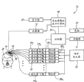
With reference to accompanying drawing, Fig. 1 is a specific embodiment having concentrated hyperacoustic system 10 according to the present invention, and it comprises imager 12, acoustic wave transducer 14, beam-forming device or signal conditioner 18, controller 20, frequency generator 22, reaches the system diagram picture and shows computer 40.Alternatively, system 10 also can comprise user interface 25, as touch screen, keyboard and/or mouse (not shown), and/or display 27.System 10 can measure the characteristic in patient 30 the skull 28, and/or acoustic energy can be delivered to the tissue in the skull 28, and is as described below.Preferably, this system is used to transmit acoustic energy, for example, acoustic energy is delivered to tissue or other tissue district in the skull 28 between 10 kilo hertzs (0.01MHz) and 10 megahertzes (10MHz).
Transducer 14 comprises a plurality of " n " element of transducer 16 (" n " is the integer greater than 1), thereby a kind of transducer group of multicomponent is provided.Transducer 14 can comprise flexible or semirigid substrate or panel, and this substrate or panel can be consistent with the shape of skull 28.As shown in Figure 1, transducer 14 can prebend (as bending to sphere or other concave), thus transducer 14 can be arranged on the top of a part of skull 28 or near.Alternatively, transducer 14 can be planar, parabolical or any other suitable shape (as circular, oval or the like).
Element of transducer 16 can be installed on the substrate of transducer 14 by preassigned pattern, perhaps in other words, is arranged on the substrate of transducer 14.For example, element of transducer 16 can be provided with (not shown) around the central shaft setting or with the orthogonal grid pattern substantially symmetrically.Element of transducer 16 can be installed in the silicone rubber or any other is suitable for preventing in the material of any mechanical connection between the element of transducer 16.In typical embodiment, element of transducer 16 can be 1 square centimeter of (1cm 2) piezo ceramic element.Also can adopt other material, for example, element of transducer 16 can be made up of one or more piezoelectricity synthetic materials or other material that can convert electric energy to acoustic energy.In order to ensure can be with the power conversion of maximum to element of transducer 16, element of transducer 16 can be arranged under the characteristic frequency so that electric resonance to take place, and the load that makes amplifier 24 mainly is ohmic.
The element of transducer 16 of transducer 14 can be electrically coupled to signal conditioner 18, and signal conditioner 18 is electrically coupled to frequency generator 22 successively.Frequency generator 22 can provide shared radio frequency (RF) the signal input signal as signal conditioner 18.Frequency generator 22 can be the generator that can produce proper signal for signal conditioner 18 of any kind of.Simultaneously, frequency generator 22 and signal conditioner 18 drive one element of transducer 16 with pumping signal together, so that element of transducer 16 transmits acoustic energy.Preferably, the pumping signal that offers each element of transducer 16 has identical frequency, but has different phase places and/or amplitude, to transmit acoustic energy by skull 28 and to make the selection area of concentration of energy in skull 28, that is (not shown) in patient's brain.
Signal can offer the element of transducer 16 of transducer 14 by drive arrangements, this drive arrangements is similar to people such as Daum at " Design and Evaluation of a FeedbackBased Phased Array System for Ultrasound Surgery ", IEEE Trans.Ultrason.Ferroelectr.Freq.Control 45 (2): 431-4, the drive arrangements of report in 1998, but driving frequency is between about 100 kilo hertzs (100kHz) and about 10 megahertzes (10MHz).The power of each element of transducer 16 and phase place can Artificial Control or use software and feedback controls automatically.
Preferably, signal conditioner 18 comprises a plurality of " n " amplifier 24 1-24 n" n " phase regulator 26 1-26 n(wherein " n " is corresponding to the number of the element of transducer 16 that is coupled to signal conditioner 18), signal conditioner is coupling in the amplifier 24 of corresponding cover and phase regulator 26.Input signal from frequency generator 22 is separated, so that each phase regulator 26 can receive the signal from frequency generator 22.The passage of every cover phase regulator 26 and amplifier 24 expression signal conditioners 18, this signal conditioner 18 is coupled to corresponding element of transducer 16.Phase regulator 26 can be adjusted factor alpha by respective phase 1nAdjust phase of input signals from frequency generator 22.Preferably, phase regulator 26 provides the precision (8 bit resolution) of about 1 degree, although lower phase resolution is enough for many application.
The signal that amplifier 24 can amplify from phase regulator 26 offers element of transducer 16 with the pumping signal of will be amplified, and for example, by coaxial cable or other connected mode, it can be connected respectively to amplifier 24 and corresponding element of transducer 16.Alternatively, if the channel region of corresponding element of transducer contains bubble, if the angle of incidence of wave beam is too little, perhaps because other factors all can cut off (amplitude is transferred be set at 0) with one element of transducer 16.Internal power table (not shown) in the signal conditioner 18 can be provided by the power that is provided by amplifier 24.
The phase place of phase regulator 26 is adjusted factor alpha 1nPermission is adjusted the acoustic energy that element of transducer 16 transmits, for example, allow " focal zone " (acoustic energy is focused on spatial zone) to move, as moving along " z " axle (extending to the axle of skull 28 from the transmission Surface Vertical of transducer 14, not shown) and/or along " x " or " y " axle.The component that each phase place that is associated with adjustment is adjusted coefficient can adopt known technology to calculate, and for example, adopts the distance of the average speed of sound wave in the body and the target site from each element of transducer 16 to concern (focal zone of being scheduled in the tissue district).
In addition, phase place is adjusted coefficient also can compensate the hyperacoustic phase distortion that is transmitted by each element of transducer 16, and phase distortion is by causing during by organizing in the skull 28 when acoustic energy.Each phase place that is associated with phase distortion is adjusted factor alpha 1nComponent can compensate variation and/or structural consideration (for example inflation or the fluid filled sac in the skull 28) caused perturbation and distortion (all not shown) by the bone of skull, skin/skull separating surface, cerebral dura mater/skull separating surface, skull thickness.Constitute phase place and adjust factor alpha 1nTwo components (as controlling element and phase distortion component) can determine the composite phase of corresponding passage to adjust factor alpha jointly 1n, so that ultrasound wave concentrates on respect to " z " needed steering angle of axle with apart from the required separation distance (" focal length ") of transducer 14.
Phase place is adjusted factor alpha 1nMeasured by system diagram picture and demonstration computer 40, this computer 40 can be coupled to controller 20 and imager 12.Alternatively, controller 20 itself can comprise all mensuration phase places adjustment factor alpha 1nNecessary hardware element and/or software module, rather than use independent computer 40.System diagram picture and demonstration computer 40 can comprise one or more software modules, hardware component, firmware, hard wire or these combination.For example, system diagram picture and demonstration computer 40 can be the digital data processors of general purposes or specific purposes, and this processor can adopt traditional mode to generate phase place with software programming and adjust factor alpha 1n, phase place is adjusted coefficient can be passed to controller 20, and then is delivered to phase regulator 26, perhaps is directly delivered to phase regulator 26 according to the image that receives from imager 12.
System diagram picture and demonstration computer 40 can and be paid close attention to (interest) tissue characteristics by image recognition and measure phase place adjustment factor alpha by automatic analysis image 1nCan provide enough information in system diagram picture and demonstration computer 40, to measure phase place adjustment coefficient by imager 12.Alternatively, the user can the manual analysis image and the identification tissue characteristics, perhaps can adopt automatically and mode that manual analysis combines.
At first, imager 12 can be from the skull osseous tissue border measured and skull arbitrarily other tissue district obtain the image of skull 28 inside.For example, imager 12 can be nuclear magnetic resonance (MRI) device, computerised tomography (CT) device or ultrasonic imaging (UIS) device (not shown).This image can or be preferably two dimensional image for the one dimension image by paying close attention to the cross section, position.Alternatively, also can be the 3-D view that imager 12 forms.If imager 12 is CT devices, imager 12 can be determined and (being also referred to as Hounsfield number) be provided CT number for each pixel in the image that is provided by imager 12.Disclosed in No. the 10/190th, 787, the United States Patent (USP) and adopted ultrasonic detector to obtain the exemplary embodiments of picture system.
System diagram picture and demonstration computer 40 can be generated the 3-D view of skull 28 by the image that imager 12 produces, to determine the border of skull osseous tissue by this 3-D view.For example, system diagram picture and demonstration computer can be divided into this 3-D view " volume elements (voxels) " (volume pixel of 3-D view).Then, can determine the organizational boundary that organized by imaging according to this 3-D view, as described below.Alternatively, can determine and/or infer organizational boundary by two dimensional image.The image and/or the 3-D view that are produced by imager 12 also may be displayed on the display 27, so that doctor, technician or other operator check and/or analyze.
Referring to Fig. 2, shown in the figure for the analysis adopted in the system of the present invention by the canonical process of treated tissue district image, for example, the transmission of the treatment energy of control tissue district target site.Preferably, this process can be used for concentrated hyperacoustic treatment, for example, comprise the multicomponent transducer group, this transducer group is arranged near the tissue district, is used for acoustic energy is delivered to the target site in tissue district.In a typical embodiment, this tissue district is patient's a skull, and target site is tumor or other organizational structure in patient's brain.
In step 60, imager (imager 12 as shown in Figure 1) can obtain the image of one or more target sites, for example, and the inside of patient's skull.As previously mentioned, this imager can be one of any in the multiple imaging device, as MRI device, CT device or ULS device.Image is the one dimension image at least, for example, and a plurality of vectors; Be preferably two dimensional image, for example, a plurality of plane of delineation or " fragments " of separating by the space of paying close attention to the tissue district.For example this tissue district can be a skull, and image can be a plurality of fragments (slices) by skull, to be used to discern tumor or other organizational structure in patient's brain.
In step 62, the view data of rendering image is delivered to processor, system diagram picture as shown in Figure 1 and show computer 40.In one embodiment, imager 12 and system diagram picture and demonstration computer 40 can be directly interconnection, that is, and and can be in same position.In an alternative embodiment, imager 12 (being positioned at after the patient 30) can be arranged on a position, and the view data of imager 12 can be delivered to the remote system image that can receive a plurality of imager data and show in computer 40 (not shown).This transmission can be finished by any wired or wireless network, as telephone network or the Internet.Therefore, the center system image and show computer 40 can with a plurality of far swap datas, for example, hospital or other treatment mechanism.
As long as obtained patient's image, just can transmit view data immediately, for example, if the patient is just in therapeutic process.Alternatively, view data can be stored in the imager position, for example, and in memorizer or in the CD (CD) or in other portable memory.Therefore, certain time before finishing treatment, just can obtain one of this tissue district and overlap reference picture.This transmission can be finished automatically, perhaps can only finish according to doctor or other operator's instruction.
In case processor (as system diagram picture and demonstration computer 40) has received view data, view data just can be processed to generate one or more 3-D views and/or to generate the treatment parameter.For example, in the step 64, can generate in the tissue district 3-D view of some tissue at least, this can be divided into types of organization.This analysis can comprise channel region, that is, part tissue district is positioned at and is used for the treatment of between patient's transducer and the quilt organizational structure for the treatment of.Preferably, this analysis comprises the channel region of each element of transducer of transducer group, that is, acoustic energy is delivered to the passage of target site from corresponding element of transducer by intermediate structure.Can add 3-D view from a plurality of two dimensional images, for example, the contiguous space of filling separates the gap between the image segments, thereby has created the 3-D view that is used for subsequent analysis.Alternatively, can the direct analysis two dimensional image.
In step 66,3-D view (or alternatively, two dimensional image) can be cut apart and is categorized into types of organization, for example, determines by the border between the histological types in the tissue district of imaging.This image can be defined by corresponding " volume elements " (the area pixel of the volume pixel of 3-D view or two dimensional image).Each volume elements (voxel) in the image can be mapped to position data set automatically, and is associated with types of organization.For example, each volume elements (voxel) can designated coordinate be discerned its locus, as, (X Y) is used for two-dimensional position data collection, (X, Y Z) is used for the three-dimensional location data collection, and types of organization (T), the result comprises coordinate (X in each volume elements of data centralization (voxel), Y, T) or (X, Y, Z, T).
Processor (as system diagram picture and demonstration computer 40) adopts known algorithm can determine types of organization automatically.For example, the intensity that adopts the parts of images that method well known in the art (as the anatomy template matching) can produce imager is associated with different types of organization.Alternatively, the operator can study these perspective views (rendering, image) and/or image is discerned the pairing histological types of independent volume elements (voxels).
Given volume elements (voxel) data set can be cut apart then, for example, determines to be imaged at the border between the one or more histological types in the tissue district in the view data.For in the example of patient's skull, comprise border, the border between skin/skull interface and/or the border between cerebral dura mater/skull interface determined between the interior organized layer of skull bone itself in the tissue district.
This process can be automatic, automanual or artificial.For example, doctor or other operator can studies show that the image on the device, and by following the trail of border between one or more allied organizations type, waiting the artificially to cut apart them by changing the border.Suitable interface device (maybe can control the mouse of the indicator on the display of display image as touch screen) can be used to identification and be connected similar types of organization.
In semi-automatic cutting techniques, can adopt the area algorithm of expansion to fill specified each image area by the user according to the variation of intensity in the image.For example, click the mouse when indicator is positioned at the image that a part has first intensity, the types of organization that perhaps is identified can finish the area algorithm of expansion, has the whole zone of similar strength or types of organization with the pad indicator identification division.Alternatively, can adopt the full automatic algorithm of cutting apart to cut apart each tissue district according to variation or other sorting parameter of intensity in the image.
If two dimensional image is cut apart, cut apart in case finish, will add the 3-D view in one or more tissues district from the two dimensional image that a plurality of spaces separate.The quantity of adding a necessary two dimensional image of effective 3-D view depends on the geometry ratio of tissue district variation and the required degree of accuracy of interpolation, and this is that those skilled in the art can finish.
In step 68, can measure correction coefficient according to two dimension or 3-D view, can be used for auxiliary tissue district treatment subsequently.Disclosed the canonical system of measuring these correction coefficients in No. the 09/738th, 514, the United States Patent (USP).In one embodiment, correction coefficient has been explained the different velocities of sound, will cause sonic velocity change during the histological types of acoustic energy by corresponding divided tissue district.In addition or alternatively, correction coefficient can be explained the refraction of acoustic energy, this refraction occurs in the border of being cut apart the tissue district, will illustrate further below.
Final correction coefficient (as coefficient of phase displacement and/or peak factor) can be used to the auxiliary special course of treatment, preferably, acoustic energy is concentrated on by the target site in the tissue district of imaging.For example, in step 70, correction coefficient can be delivered to and concentrate in hyperacoustic system controller 20 as shown in Figure 1, signal conditioner 18 and transducer 14.
In step 72, concentrated hyperacoustic system can use correction coefficient to control wave beam model or signal conditioner, signal conditioner 18 as shown in Figure 1, it can will encourage or drive signal according to correction coefficient and be delivered to transducer.For example, continuation can offer signal conditioner 18 with one or more basis signal with reference to Fig. 1, can be separated into a plurality of passages as (as previously mentioned) basis signal is provided by frequency generator 22, preferably, corresponding transducer 14 corresponding element of transducers 16 enter into corresponding passage.Signal conditioner 18 can be regulated the signal phase of corresponding passage according to the phasing coefficient that controller 20 receives.For example, can control phase compensate from corresponding element of transducer 16 pass through histological types and/or through the acoustic energy of one or more organizational boundaries.Except other phase place adjustment, can be used for concentrating acoustic energy at the focal zone of ad-hoc location or given shape, or the variation of compensation element of transducer, this is well known to a person skilled in the art.Phase adjustment signal can be amplified according to the correction of amplitude coefficient, as by amplifier 24, can amplify pumping signal.Alternatively, the signal of corresponding passage can be exaggerated before by phase adjusted.
In step 74, can be delivered to transducer 14 with phase-adjusted pumping signal and drive corresponding element of transducer 16 what be exaggerated.Element of transducer 16 converts this pumping signal to acoustic energy, this acoustic energy can from transducer 14 corresponding element of transducers 16 be delivered to patient 30 by the tissue district of imaging, for example, by any intermediate structure target site of (in skull 28) in tissue district.
In therapeutic process, can obtain image, for example, employing can obtain the same imager of reference image data, the carrying out that comes monitor treatment.For example, image can be passed to processor (system diagram picture as shown in Figure 1 and show computer 40), is used in real time or approaches real-time monitoring.The treatment image that is obtained is compared with the previous reference picture that obtains.If necessary, can the adjustment of treatment parameter, as the incident (as adopting aforementioned same process) that they are showed by the energy that provides further amplitude and/or phasing coefficient to revise to be delivered to the tissue district and reflection, thereby treatment is transformed in the process that can control.
With reference to figure 3, the mensuration that system of the present invention adopted excitation correction coefficient has been described with the process of compensation acoustic energy among the figure by the phase shift of skull tissue, acoustic energy is the normal of organizational boundary or near normal.As shown in the figure, skull 28 comprises two-layer cortical bone 50,54 and intermediate layer spinal bone 52.As shown in the figure, element of transducer 16 xNear skull 28, at vector 96 and skull at a r 0On the direction of propagation that intersects acoustic energy is transmitted in the skull 28.From the 3-D view of skull 28, can determine the from the beginning focus r on the bone surface 38 of two vertical vectors, 88,90, two vectors 0Respectively in the x and y direction or other imaging coordinate system extend along the surface 38 of skull 28.Adopt known method, can come the normal line vector 94 of gauging surface 38 with vector 88,90.Can calculate the vector 94 that to discern angle of incidence and the scalar product of vector 96.
Every layer 50,52 and 54 thickness D 1, D 2And D 3Can utilize intensive variable to calculate, at the position on skull surface r 0=(x 0, y 0, z 0) beginning, the some r=to following one deck 52 (x, y, z),
r=r 0+D n (1)
Can between successive layer, repeat this process, begin the surface that enters to one deck down from the surface that enters of layer n.Above-mentioned discussion is that supposition is propagated near normal by skull, and the different layers 50,52 and 54 of supposition skull osseous tissue is a homogeneity separately.For the purpose of ultrasonic propagation velocity, regard layer 50,52 and 54 every layer as simple layer, according to propagation, can adopt simple relation to express phase shift by set point on the skull.
φ = 360 fD ( 1 c 0 - 1 c s ) - - - ( 2 )
Wherein, f is a driving frequency, c 0Be sound wave average speed in tissue, c sBe the speed of sound wave in the skull osseous tissue, and D is the thickness of skull.
The inhomogeneity of tissue can cause refraction and change route, thereby change the distance that ultrasonic energy is propagated along this route.So just further shifted the phase place of the ultrasonic energy that transmits by element of transducer in the focal zone, reduced constructive interference like this, thereby reduced the intensity of the ultrasonic energy that is delivered to focal zone.
If do not suppose near normal and propagate (with reference to Fig. 3), when measuring the drive factor (shown in the step 68 of Fig. 2) of element of transducer, will consider the refraction of the ultrasonic energy at place, one or more boundary region, so the constructive interference of focal zone ultrasonic energy will be maximized.
Can adopt the Snell rule to describe the ultrasonic beam refraction:
Sin θ 1 Sin θ 2 = C 1 C 2 - - - ( 3 )
Wherein, θ 1And θ 2Be the angle between line of incidence and the fringence in normal to a surface and the corresponding tissue district, and C 1, C 2Be the speed of sound wave in corresponding tissue district.Because the border between soft tissue and bone refraction is very serious, revise that to organize deviation be useful especially so in ultrasonic energy treatment brain, consider refraction.
Fig. 4 is the channel region Z1 that extends between transducer group 14 and target site (being determined by focal zone P1), and this target site can be other organizational structure in tumor or the cerebral tissue 69.In this simply illustrated, transducer group 14 comprised row's element of transducer 16, and the patient skin 70 of close skull osseous tissue 72 tops.As shown in the figure, connection material layer 74 (as water or sound wave gel) can be set between transducer group 14 and skin 70, connect with the sound wave that improves between transducer 14 and the skin 70.
As mentioned above, skull osseous tissue 72 generally includes the spinal column osteoplaque between two-layer cortical bone.Spinal bone has different density with cortical bone, and this just makes the velocity of sound difference separately by them.Yet as first approximation, skull osseous tissue 72 can be considered to homogeneity, can adopt average speed 3000 meter per seconds (3000m/s) of sound wave in this tissue district for whole skull osseous tissue district 72.Alternatively, maybe must improve the spatial peak power of focus (being passed to the peak power intensity of focal zone) if desired, can be cut apart the multilamellar osseous tissue (not illustrating among the figure) in the skull 72, according to instruction of the present invention, each can be considered separately by the velocity of sound of cut section with by each distance of being propagated by cut section.
Continuation is with reference to Fig. 4, if do not reflect by organizing, representational element of transducer 16a, the 16b on the transducer group 14 can directly transmit acoustic energy and make its focal zone P1 that concentrates on expection, respectively shown in ray B1 and B2.Because acoustic energy at least can be two position refractions, as the border between the border between skin 70 and the bone 72 and bone 72 and the cerebral tissue 69, so these rays do not reflect the actual path of the acoustic energy that element of transducer 16a and 16b are transmitted.Notice that acoustic energy is the normal of organizational boundary, can not reflected by this border.
For example, because the refraction of the boundary between skin histology 70 and the osseous tissue 72, ray R1 represents the actual path of the acoustic energy that element of transducer 16a is transmitted.Because the refraction of the boundary between osseous tissue 72 and the cerebral tissue 69, thereby ray R2 represents that acoustic energy passes through the actual path of cerebral tissue 69 to actual focal district P1.Because refraction, the distance of acoustic energy propagates is different with the distance of expection, and therefore, owing to the variation route of element of transducer 16a to focal zone P1, the phase place of acoustic energy changes over actual value by the desired value of focal zone P1.(for the purpose of illustrating, in phased array, focus is by the definition of electronics phasor, and this phasor provides data to element.In situation shown in Figure 4, different phasors can shift back P1 from P1 ' with focus, and following use ray R3 and R4 make an explanation)
Because the refraction of the acoustic energy that corresponding element of transducer 16 is transmitted is considered in the refraction that the inhomogeneity of tissue causes, can finish the calculating of one or more ray between element of transducer 16 and the expection focal zone P1 in order to compensate.For example, ray R3 shown in Figure 4 and R4, be illustrated in considered refraction after, what the acoustic energy that element of transducer 16a is transmitted concentrated on focal zone P1 must be through round.Can from the calculating of front, add these rays, as, determine acoustic energy from the transmission point of corresponding element of transducer 16 by different tissue districts up to reach the route that is experienced till the phase shift of expectation at focal zone, interfere to create desired mechanism.Alternatively, can finish opposite ray and calculate, begin at focal zone P1 place, by different tissue districts to corresponding element of transducer 16.As previously mentioned, with reference to formula 3, the Snell rule has been considered in the calculating of these rays, and this is that those skilled in the art can finish.
Can calculate the length of every ray, the length of ray is that the distance of the acoustic energy that transmitted with corresponding element of transducer is corresponding.For example, the distance L 3 of the ray R3 that extends by skull osseous tissue 72 can be calculated by borderline volume elements (voxel) coordinate that identification is intercepted by ray R3.If between skin 70 and the skull osseous tissue 72 by the volume elements of partitioning boundary (voxel) coordinate be (Xa, Ya, Za), between skull osseous tissue 72 and the cerebral tissue 69 is (Xb by the volume elements of partitioning boundary (voxel) coordinate, Yb, Zb), the propagation distance L3 of ray R3 between the border is so:
L3=((Xa-Xb) 2+(Ya-Yb) 2+(Za-Zb) 2) 1/2. (4)
Distance L 3 in the equation 4 can be used to determine the phase shift that is caused by skull osseous tissue 72, and measures necessary coefficient of phase displacement α 1n
Owing to be used to measure the phase shift factor alpha usually in the bodily tissue 1nBulk sound velocity and the actual speed of sound wave in cerebral tissue 69 different, cerebral tissue 69 also can cause the phase shift in the acoustic energy.According to volume elements (voxel) coordinate on border between the skull osseous tissue 72 and volume elements (voxel) coordinate of focal zone P1, can calculate the propagation distance L4 of second ray R4, with further correction phase shift by cerebral tissue 69 to focal zone P1.
The acoustic energy that is adopted in the ultrasonic therapy is typical continuous wave, but not discrete ray, but the ray that is to use should be represented fully that ripple itself can be finished quite accurately and calculates.Because element of transducer has size limited, each element adopts many rays to calculate the necessary phase place of every ray and uses the average phase of this element can improve degree of accuracy.The result can be an iterative process, supposes that ray is to determine the acoustic energy concentration zones of target site by successive organized layer border up to measuring suitable correction coefficient.
The excitation correction coefficient can adopt phase place or speed governing to calculate.Replacing calculating with the transmission speed regulating control under the situation of coefficient of phase displacement, the excitation correction coefficient is based on the acoustic energy that is refracted by one or more actual propagation times of being cut apart the tissue district.The actual propagation time can be used for measuring the passing time that is corrected of each element of transducer 16, so the acoustic energy that has element of transducer 16 to transmit can constructive interference at focal zone P1.
Ray R by the propagation time T in tissue district is:
T = L V Sec , - - - ( 5 )
Wherein, V is the speed (for example, skull osseous tissue be 3000 meter per seconds (3000m/ss)) of sound wave by organizing, and L is the length of ray R in the tissue, that is, and and the distance that typical ray is propagated by the tissue district.
With reference to the described example of Fig. 4, when using transducer 14 in brain 69, to adopt ultrasonic therapy, can measure track and propagation time from the acoustic energy of corresponding element of transducer.For example, shown in ray R3, acoustic energy to can using the velocity of sound by osseous tissue (as, 3000 meter per seconds (3000m/s)) to measure by the propagation time of skull bone 72, and is used to calculation correction time delay by element of transducer 16a.For because the caused phasing of passage by cerebral tissue 69, can adopt equation 4 and sound wave is the propagation time that 1570 meter per seconds (m/s) are measured typical ray R4 at the cerebral tissue medium velocity.Like this, the propagation time of ray R3 and R4 just can come together to calculate the propagation time of the acoustic energy that element of transducer 16a transmitted, and to revise the inhomogeneity of tissue, comprises refraction.
The gauged propagation time that is delivered to the refracted rays of focal zone P1 by element of transducer 16b and other element of transducer 16 can be calculated by similar mode.Correction propagation time of each element of transducer 16 is offered processor (as to be connected to controller 20 or the system diagram picture on the transducer 14 and to show that computer 40 is (referring to Fig. 1, do not illustrate among the figure)), postpone the correction time that is delivered to the pumping signal of each element of transducer 16 with decision, so the correction acoustic energy that transducer 14 is transmitted can constructive interference at focal zone P1.
As mentioned above, if necessary, when measuring owing to the caused phase compensation of propagation distance in the corresponding organized layer of three layer model, can consider the refraction (three layers of osseous tissue layer 50,52 and 54 as shown in Figure 3) in a plurality of osseous tissue layers, can suppose that skull is made up of single conforming layer, the velocity of sound and bone density linear correlation (thereby with to the velocity of sound) are as being measured by CT or ultrasonography.For example, the velocity of sound in intermediate layer 52 is near 2500 meter per seconds (m/s), and the velocity of sound of internal layer 50 and skin 54 is 2900 meter per seconds (m/s).Adopt three layer model to be by the expection phase shift of skull 28:
φ = 360 f Σ n = 1 3 D n ( 1 c s - 1 c n ) - - - ( 6 )
Wherein, C nEqual the velocity of sound of n layer, D nBe the thickness of n layer.
Because the local density of skull 28 can influence the propagation by skull 28, the concentrating of the acoustic energy that can improvement group 14 transmits based on the phasing of skull density.In order to estimate the internal density difference, the average CT image intensity along ultrasonic propagation axle (vector 96 as shown in Figure 3) can be associated with the velocity of sound to expecting that individual course evenly is worth the influence of deviation (being calculated by previous equations 2).Adopt 3-D view, as the 3-D view by the two-dimensional ct image creation, each volume elements (voxel) can be endowed an intensity level, supposes this intensity and bone density linear correlation, and density unit is MKS, and the empty G﹠W in the employing image is as reference density.The CT intensity level addition of the propagation axis 96 in bone 28 can be measured mean intensity divided by the sum of volume elements (voxel) again.Volume elements (Voxel) can comprise inflation or fluid filled sac.Suppose that the velocity of sound in the fluid filled sac equals the velocity of sound in the water.Also can suppose and when acoustic energy is run into gas cell, can take place to reflect fully.
The phasing that is produced by skull density can adopt empirical formula to calculate, as, as the actual measurement phase shift that causes by skull by acoustic energy different with between notional phase in the equation 2 (single-layer model) moves.Can obtain theoretical correction coefficient by the percent error that fits (adopting polynomial curve to fit) mean intensity function, that is:
Figure C200380107444D00231
Wherein, fitted N+1 coefficient A for the N degree n, ρ is a density, and 117 point data collection under 0.51 megahertz and 5 skulls are fitted the generation coefficient through three times, unit is MKS,
Table 1
A 0 1.1424e-008
A 1 -7.5377e-005
A 2 0.1645
A 3 -118.689
These coefficients can be used for equation 7, can adopt the correction coefficient of being calculated by equation 7 to calculate gauged phase shift in the following formula in monolayer homogeneous model equation 2,
φ = Φ 1 + C , - - - ( 8 )
Wherein, Φ comprises the initial phase place value that adopts equation 2 to obtain.
The measured value of density and thickness also can be used for regulating the velocity of sound of skull.For regulating the velocity of sound in the simple layer, can fit the velocity of sound of density function according to following formula:
c s ( ρ ) = [ 1 c 0 - φ ( ρ ) 360 fD ] - 1 - - - ( 9 )
Wherein, Φ (ρ) is the measurement phase shift of density function.Multinomial shown in the equation 7 fits and can be used for calculating acoustic velocity value.For three layer model, calculate two velocities of sound.These two speed C that the velocity of sound is a cortex iAnd the speed C of spinal column (central authorities) bone Ii, given three osteoplaques 50,52 and 54 thickness are respectively D 1, D 2And D 3, fit the cortex speed C of density function according to following formula i:
c i ( ρ ) = ( D 1 + D 3 ) [ D 1 + D 2 + D 3 c 0 - D 2 c ii - φ ( ρ ) 360 fD ] - 1 . - - - ( 10 )
Adopt equation 7 by the ternary function C IiProgression finish C iMultinomial (ρ) fits.Finally obtain velocity of sound C i(ρ) and C Ii(ρ), C i(ρ) and C Ii(ρ) closely related, perhaps closely related by other method that fits a large amount of resultant straight joint bone measurement of skull sample values by standard deviation.
The power that offers patient's skull depends on the treatment type.Have in the concentrated ultrasonic ablation process of transducer group of a plurality of elements in employing, transmitted the electrical power of about 1 to 3 kilowatt (1-3kW) in about 10 to 30 (10-30) seconds.In order to open brain blood barrier, adopt than low about 100 times power in the ablation procedure, as, owing to pay close attention to the preformed bubble in district.Preformed bubble can reduce ablation power.If set wave will occur owing to element of transducer 16 transmits energy continuously, so if utilize energy pulse can not eliminate the influence that also can reduce to phase place.
With reference to Fig. 5, system and method described herein also can be used for acoustic energy is delivered to target site (as after being positioned at fat deposit) in the soft tissue.Ultrasonic therapeutical system 10 is identical or similar with system 10 among Fig. 1, and therefore similarly part can adopt similar label.Transducer 14 comprises a plurality of element of transducers 16, can be arranged on patient 30 the outer surface or near.Transducer 14 can be taked any suitable shape, comprises as bending, flat and/or parabolic shape.Preferably, transducer 14 is used for concentrating ultrasonic energy from transducer group 14 surfaces with needed focal length, that is, enter in patient's 30 bodies.
Channel region comprises soft tissue, as one or more region of adipose tissue, since the region of adipose tissue in the channel region, the phase shift that can proofread and correct acoustic energy.(promptly do not comprise osseous tissue) in soft tissue, fatty tissue can produce bigger phase shift than other soft tissue (as muscle or organ).For example, the velocity of sound in the fatty tissue is different from the bulk sound velocity (near 1540 meter per seconds (m/s)) that is adopted usually near 1460 meter per seconds (m/s) in conventional program.As previously mentioned, owing to reduced the constructive interference of the acoustic energy of whole element of transducers transmission, the difference of local sonic speed has seriously reduced the intensity of the acoustic energy that is delivered to focal zone.
For other soft tissue type, the velocity of sound of muscular tissue and bulk sound velocity difference are maximum, promptly near 1600 meter per seconds (m/s).Muscular tissue has caused phase shift, has reduced constructive interference, and this influence is lower than the influence of region of adipose tissue usually basically, therefore in most of the cases can ignore.In organ-tissue, the velocity of sound of liver is near 1555 meter per seconds (m/s), and the velocity of sound in the kidney is near 1565 meter per seconds (m/s).The deviation that this and bulk sound velocity is very little only can cause very little or negligible distortion, and except ultrasonic energy superlatively being transferred to focal zone, this distortion is negligible.
Owing to provide maximum improvement (to compare for the energy delivery of focal zone with other soft tissue to the correction of region of adipose tissue distortion, suppose at channel region and do not have osseous tissue, perhaps provide phasing) to the osseous tissue in the channel region, so can cut apart region of adipose tissue, use with the similar method of aforementioned calculating osseous tissue according to the velocity of sound of region of adipose tissue reality with by the refraction that region of adipose tissue causes and calculate the excitation correction coefficient.
Alternatively, for the added improvement in realize proofreading and correct and consequent added improvement in energy delivery can be cut apart the muscular tissue district, and adopt the velocity of sound in muscular tissue district and calculate the excitation correction coefficient by the refraction that the muscular tissue district causes.Remaining soft tissue area (non-fat and muscular tissue district) can be regarded the part in muscular tissue district as, perhaps if necessary, can cut apart separately and analyze.
According to the segmented shape in tissue district, the actual focal district that the acoustic energy of transducer transmission can move at the focal zone for expectation carries out constructive interference.For example, Figure 6 shows that a typical tissue district, comprise the divided region of adipose tissue 180 in the channel region 72 between transducer 14 and needed focal zone P2.Suppose that the remaining tissue between transducer 14 and region of adipose tissue 180 182 is muscular tissue.For simplified embodiment, other in the channel region 72 do not organized and illustrated.Typical divided region of adipose tissue 180 is in that to pass basically on the plane of extending with the plane parallel of transducer 14 definition varied in thickness even.The rate of change of depth distance is constant (increase continuously or reduce) and linear (be border can by equation Y=a+bx definition).Therefore the tissue district can be modeled to prism.
Represented among the figure at the element of transducer 16a at the two ends of transducer 14 and the typical ray B3 and the B4 of two acoustic energy that 16b transmits respectively.Plan is that ray B3 and B4 are concentrated on needed focal zone P2, and is shown in dotted line.Needed focal zone P2 is selected by the operator of treatment, adopts imaging system as previously described.Yet as shown in the figure, refraction makes ray B3 and B4 (acoustic energy that other element of transducer 16 of transducer 14 is transmitted is similar) concentrate on the new focal zone P4 that is different from needed focal zone P2.
Solid line B3 ', B3 ", B4 ' and B4 " represent wave beam B3 and B4 by fatty tissue prism 180 and by after actual path (comparing with dotted line) if the route that dotted line is passed through for not reflecting acoustic energy.Because the change in depth rate in tissue district 180 is constant and linearity, so when acoustic energy distinguished 180 by tissue, acoustic energy was to pass wave beam pari passu to reflect.The phase place of wave beam is pro rata to be shifted, and wave beam can constructive interference at the focal zone P4 of reality like this.Although desired energy delivery intensity does not appear at the focal zone P2 of expectation, do not obtain any reduction in the constructive interference of the focal zone P4 that has shifted.
Owing to tissue district's 180 refractions that cause cause the transfer of focal zone P2 to proofread and correct, adopt foregoing method as reference Fig. 2, make the acoustic energy wave beam get back to needed focal zone P2.Can measure coefficient of phase displacement α 1nOr the correction propagation time of each element of transducer, calculate as adopting the front or opposite as previously mentioned ray.
Consider Snell rule (equation 3 as described above), organize the velocity of sound in (muscle) tissue district that distinguishes 180 divided borders and tissue district 180 and vicinity, similar with the described method in front, new ray R6, R7 and R8 are depicted as the needed actual path of acoustic energy that element of transducer 16 transmits.For other element of transducer 16 of transducer 14, can compute classes like ray and the phasing coefficient that thereupon produces to offer the acoustic energy wave beam that concentrates on the focal zone P2.
The correction of when considering refraction focal zone being moved is that trimming process institute is inherent, as described herein, and the software of finishing trimming process can allow defocusing independent correction (promptly reducing the constructive interference of focal zone) and proofreading and correct the focal zone conversion is independent.In some cases, only need maybe to proofread and correct one or another.For example, organize the distortion meeting to change the direction of focal zone and exceed the Electronic Control ability institute of transducer can gauged scope (as because element is inadequately little).In this case, can adopt the correction calculation rule to attempt the control focal zone and make it get back to needed focal zone, still, because this is impossible, most of energy can not be delivered to desired location.In this case, can mechanically mobile transducer, for example, along the surface of organizational structure, so that focal zone head for target position again.
With reference to as 7, be another embodiment that can be used as the divided tissue district 190 of prism model shown in the figure, these prismatical two face 192a and 192b and prismatical summit 194 can intercept the acoustic energy that transducer 14 is transmitted.In the embodiment that originally illustrates, suppose that the rate of change apart from the degree of depth by each face 192a and 192b is constant and is linear.The acoustic energy that transducer 14 is transmitted that is provided with in tissue district 190 is divided into two parts basically.
Shown three typical acoustic energy ray B6, B7 and B8 transmit by corresponding element of transducer 16a, 16b and 16c.The represented acoustic energy of ray B6, B7 and B8 is concentrated on focal zone P6 by expection.Yet, because the refraction in prismatic shape tissue district 190, ray B7 and B8 (and the impact of transmitting by transducer is distinguished other acoustic energy on the 190 border 192b at tissue) are focused on the focal zone P8 of reality.Ray B6 (and other acoustic energy on the impact border 192a of transducer transmission) is focused on focal zone P10, thereby will be divided into two parts effectively by the acoustic energy that transducer 14 transmits.
For needed focal zone P6, focal zone P8 and P10 are symmetrical distribution.Focal zone P8 that each moves and P10 can receive the acoustic energy that the expection of making an appointment with half is delivered to required focal zone P6.When acoustic energy was separated and is delivered to the focal zone P8 that is symmetrically distributed substantially with required focal zone P6 and P10, the acoustic energy that concentrates on each focal zone P8 and P10 can constructive interference in known error.As previously mentioned, impacting tissue district 190 each borderline acoustic energy wave beam can be corrected, so that the acoustic energy that transducer 14 is transmitted concentrates on required focal zone P6.
As Fig. 1 and transducer 14 shown in Figure 5 can comprise with shown in the element of transducer 16 of different numbers.Coefficient of phase displacement α 1nCan be stored in advance in the passage of signal conditioner 18 rather than by transducer 20 provides.And, aforesaid function can be by imager 12, signal conditioner 18, system diagram picture and show computer 40 and/or adopt system 10 to finish by the operator, for example, bulk density, determine types of organization and/or organizational boundary and/or correction data (for example, coefficient of phase displacement α is provided for controller 20 and/or signal conditioner 18 1nAnd/or be used for driving the amplitude of the pumping signal of element of transducer 16).

Claims (10)

1. one kind is used for acoustic energy is delivered to the system of tissue district target site by intermediate structure, comprising:
Transducer group comprises a plurality of element of transducers, is used for acoustic energy is transmitted to described target site by described intermediate structure along corresponding channel region;
Imager is used to generate the picture in described tissue district, and described imager generates the view data of the types of organization that comprises described intermediate structure;
Processor, with described imager coupling, be used to receive described view data, described processor is used for determining the border between a plurality of types of organizations in the described intermediate structure, and generate the correction coefficient be used for described element of transducer, in order to compensate the sonic velocity change of described types of organization in the place, described border between the described types of organization takes place in the corresponding channel region refraction and the corresponding channel region; And
Controller, with described processor and the coupling of described transducer group, described controller is used to receive the described correction coefficient from described processor, and pumping signal is offered described element of transducer so that the described acoustic energy that described element of transducer transmits concentrates on described target site according to corresponding correction coefficient.
2. system according to claim 1, wherein, described imager comprises at least one in nuclear magnetic resonance device, computerised tomography imager and the ultrasonic imaging device.
3. system according to claim 1, wherein, described imager is used to generate intensity data, and described intensity data comprises the relative density of corresponding types of organization, and wherein said processor is used to analyze described intensity data to discern a plurality of types of organizations.
4. system according to claim 1, wherein, described imager is used to generate a plurality of two dimensional images that comprise described intermediate structure.
5. system according to claim 4, wherein, described processor is used for converting a plurality of two dimensional images to comprise described intermediate structure one or more 3-D views.
6. system according to claim 5, wherein, described processor is used for automatically determining the described border between a plurality of types of organizations in the described intermediate structure according to described one or more 3-D views.
7. system according to claim 5 further comprises:
Display is used to show described one or more 3-D view; And
User interface is used for interacting to discern the types of organization in the described intermediate structure with described one or more 3-D views.
8. system according to claim 4, wherein, described processor is used for according to the described border between the automatically definite a plurality of types of organizations of described two dimensional image.
9. system according to claim 1, wherein, described correction coefficient comprises the phasing coefficient that is associated with corresponding element of transducer, wherein said controller comprises phase regulator, is used for offering according to described phasing coefficient adjustment the phase place of the pumping signal of corresponding element of transducer.
10. system according to claim 9, wherein, described correction coefficient comprises the correction of amplitude coefficient that is associated with corresponding element of transducer, wherein said controller further comprises and the coupled one or more amplifiers of described phase regulator, is used for will offering according to described correction of amplitude coefficient the described pumping signal amplification of corresponding element of transducer.
CNB2003801074445A 2002-12-23 2003-12-01 Tissue aberration corrections in ultrasound therapy Expired - Lifetime CN100479889C (en)

Applications Claiming Priority (2)

Application Number Priority Date Filing Date Title
US10/328,584 2002-12-23
US10/328,584 US8088067B2 (en) 2002-12-23 2002-12-23 Tissue aberration corrections in ultrasound therapy

Publications (2)

Publication Number Publication Date
CN1732031A CN1732031A (en) 2006-02-08
CN100479889C true CN100479889C (en) 2009-04-22

Family

ID=32594519

Family Applications (1)

Application Number Title Priority Date Filing Date
CNB2003801074445A Expired - Lifetime CN100479889C (en) 2002-12-23 2003-12-01 Tissue aberration corrections in ultrasound therapy

Country Status (8)

Country Link
US (1) US8088067B2 (en)
EP (1) EP1581306B1 (en)
JP (1) JP4558504B2 (en)
CN (1) CN100479889C (en)
AT (1) ATE466624T1 (en)
AU (1) AU2003303187A1 (en)
DE (1) DE60332490D1 (en)
WO (1) WO2004056421A1 (en)

Families Citing this family (170)

* Cited by examiner, † Cited by third party
Publication number Priority date Publication date Assignee Title
US6050943A (en) 1997-10-14 2000-04-18 Guided Therapy Systems, Inc. Imaging, therapy, and temperature monitoring ultrasonic system
US8256430B2 (en) 2001-06-15 2012-09-04 Monteris Medical, Inc. Hyperthermia treatment and probe therefor
US6618620B1 (en) 2000-11-28 2003-09-09 Txsonics Ltd. Apparatus for controlling thermal dosing in an thermal treatment system
US7914453B2 (en) 2000-12-28 2011-03-29 Ardent Sound, Inc. Visual imaging system for ultrasonic probe
US8088067B2 (en) 2002-12-23 2012-01-03 Insightec Ltd. Tissue aberration corrections in ultrasound therapy
US7611462B2 (en) * 2003-05-22 2009-11-03 Insightec-Image Guided Treatment Ltd. Acoustic beam forming in phased arrays including large numbers of transducer elements
US7377900B2 (en) * 2003-06-02 2008-05-27 Insightec - Image Guided Treatment Ltd. Endo-cavity focused ultrasound transducer
US7645244B2 (en) * 2004-07-09 2010-01-12 Boston Scientific Scimed, Inc. Ultrasound systems and methods for treating ischemic limbs or tissue affected by peripheral arterial disease
WO2006018837A2 (en) * 2004-08-17 2006-02-23 Technion Research & Development Foundation Ltd. Ultrasonic image-guided tissue-damaging procedure
US8409099B2 (en) 2004-08-26 2013-04-02 Insightec Ltd. Focused ultrasound system for surrounding a body tissue mass and treatment method
US7824348B2 (en) 2004-09-16 2010-11-02 Guided Therapy Systems, L.L.C. System and method for variable depth ultrasound treatment
US9011336B2 (en) * 2004-09-16 2015-04-21 Guided Therapy Systems, Llc Method and system for combined energy therapy profile
US7393325B2 (en) 2004-09-16 2008-07-01 Guided Therapy Systems, L.L.C. Method and system for ultrasound treatment with a multi-directional transducer
US8750983B2 (en) * 2004-09-20 2014-06-10 P Tech, Llc Therapeutic system
US20130046209A1 (en) 2011-07-10 2013-02-21 Guided Therapy Systems, Llc Systems and methods for improving an outside appearance of skin using ultrasound as an energy source
US10864385B2 (en) 2004-09-24 2020-12-15 Guided Therapy Systems, Llc Rejuvenating skin by heating tissue for cosmetic treatment of the face and body
US8535228B2 (en) 2004-10-06 2013-09-17 Guided Therapy Systems, Llc Method and system for noninvasive face lifts and deep tissue tightening
US8444562B2 (en) 2004-10-06 2013-05-21 Guided Therapy Systems, Llc System and method for treating muscle, tendon, ligament and cartilage tissue
US9694212B2 (en) 2004-10-06 2017-07-04 Guided Therapy Systems, Llc Method and system for ultrasound treatment of skin
EP2409730A1 (en) 2004-10-06 2012-01-25 Guided Therapy Systems, L.L.C. Method and system for ultrasound tissue treatment
US8133180B2 (en) 2004-10-06 2012-03-13 Guided Therapy Systems, L.L.C. Method and system for treating cellulite
US7758524B2 (en) 2004-10-06 2010-07-20 Guided Therapy Systems, L.L.C. Method and system for ultra-high frequency ultrasound treatment
US8690778B2 (en) 2004-10-06 2014-04-08 Guided Therapy Systems, Llc Energy-based tissue tightening
KR101328103B1 (en) 2004-10-06 2013-11-13 가이디드 테라피 시스템스, 엘.엘.씨. Method and system for noninvasive cosmetic enhancement
US9827449B2 (en) 2004-10-06 2017-11-28 Guided Therapy Systems, L.L.C. Systems for treating skin laxity
US11235179B2 (en) 2004-10-06 2022-02-01 Guided Therapy Systems, Llc Energy based skin gland treatment
US11883688B2 (en) 2004-10-06 2024-01-30 Guided Therapy Systems, Llc Energy based fat reduction
US20060111744A1 (en) 2004-10-13 2006-05-25 Guided Therapy Systems, L.L.C. Method and system for treatment of sweat glands
US11207548B2 (en) 2004-10-07 2021-12-28 Guided Therapy Systems, L.L.C. Ultrasound probe for treating skin laxity
US11724133B2 (en) 2004-10-07 2023-08-15 Guided Therapy Systems, Llc Ultrasound probe for treatment of skin
US7657101B2 (en) * 2005-01-19 2010-02-02 Dermaspect, Llc Devices and methods for identifying and monitoring changes of a suspect area on a patient
US7628756B2 (en) * 2005-03-07 2009-12-08 Terumo Cardiovascular Systems Corporation Extracorporeal emboli detector
WO2006096755A2 (en) * 2005-03-07 2006-09-14 The Brigham And Women's Hospital, Inc. Adaptive ultrasound delivery system
US20070016039A1 (en) * 2005-06-21 2007-01-18 Insightec-Image Guided Treatment Ltd. Controlled, non-linear focused ultrasound treatment
CN101252970B (en) * 2005-08-30 2011-06-15 皇家飞利浦电子股份有限公司 Combination imaging and therapy transducer with therapy transducer amplifier
US10219815B2 (en) 2005-09-22 2019-03-05 The Regents Of The University Of Michigan Histotripsy for thrombolysis
US7873181B1 (en) * 2005-09-23 2011-01-18 The United States Of America As Represented By The Administrator Of The National Aeronautics And Space Administration Visual image sensor organ replacement: implementation
WO2007058668A1 (en) * 2005-11-18 2007-05-24 Imarx Therapeutics, Inc. Ultrasound apparatus and method to treat an ischemic stroke
WO2007057704A1 (en) * 2005-11-21 2007-05-24 Inverness Medical Switzerland Gmbh Test device
EP1960993B1 (en) 2005-11-23 2016-11-02 Insightec-Image Guided Treatment, Ltd. Hierarchical switching in ultra-high density ultrasound array
US20070142699A1 (en) * 2005-12-16 2007-06-21 Acoustx Corporation Methods and implantable apparatuses for treating an esophageal disorder such as gastroesophageal reflux disease
US20070142884A1 (en) * 2005-12-16 2007-06-21 Acoustx Corporation Methods and apparatuses for treating an esophageal disorder such as gastroesophageal reflux disease
US8473239B2 (en) 2009-04-14 2013-06-25 Maui Imaging, Inc. Multiple aperture ultrasound array alignment fixture
US20070208331A1 (en) * 2006-03-02 2007-09-06 Chu Michael S Systems and methods of treatment within a gastrointestinal lumen
US8235901B2 (en) * 2006-04-26 2012-08-07 Insightec, Ltd. Focused ultrasound system with far field tail suppression
US9566454B2 (en) 2006-09-18 2017-02-14 Guided Therapy Systems, Llc Method and sysem for non-ablative acne treatment and prevention
JP4992034B2 (en) * 2006-10-13 2012-08-08 岡山県 Biological measurement device and biostimulation device
US20090024034A1 (en) * 2006-10-19 2009-01-22 Romain Moreau-Gobard Relative position determination medical ultrasound scans
US20080183077A1 (en) * 2006-10-19 2008-07-31 Siemens Corporate Research, Inc. High intensity focused ultrasound path determination
EP2088932B1 (en) 2006-10-25 2020-04-08 Maui Imaging, Inc. Method and apparatus to produce ultrasonic images using multiple apertures
US8041145B2 (en) * 2006-11-17 2011-10-18 The Invention Science Fund I, Llc Distortion compensated imaging
FR2912817B1 (en) * 2007-02-21 2009-05-22 Super Sonic Imagine Sa METHOD FOR OPTIMIZING WAVE FOCUSING THROUGH AN INTRODUCING ELEMENT OF ABERATIONS
JP2010526589A (en) 2007-05-07 2010-08-05 ガイデッド セラピー システムズ, エル.エル.シー. Method and system for modulating a mediant using acoustic energy
US20150174388A1 (en) 2007-05-07 2015-06-25 Guided Therapy Systems, Llc Methods and Systems for Ultrasound Assisted Delivery of a Medicant to Tissue
US20090088625A1 (en) * 2007-10-01 2009-04-02 Kenneth Oosting Photonic Based Non-Invasive Surgery System That Includes Automated Cell Control and Eradication Via Pre-Calculated Feed-Forward Control Plus Image Feedback Control For Targeted Energy Delivery
US8251908B2 (en) 2007-10-01 2012-08-28 Insightec Ltd. Motion compensated image-guided focused ultrasound therapy system
US9788813B2 (en) 2010-10-13 2017-10-17 Maui Imaging, Inc. Multiple aperture probe internal apparatus and cable assemblies
US9282945B2 (en) * 2009-04-14 2016-03-15 Maui Imaging, Inc. Calibration of ultrasound probes
WO2014152463A1 (en) 2013-03-15 2014-09-25 Cyberheart, Inc. Apparatus and method for real-time tracking of tissue structures
US9020576B2 (en) * 2008-03-31 2015-04-28 Okayama Prefecture Biological measurement apparatus and biological stimulation apparatus
JP5235477B2 (en) * 2008-04-14 2013-07-10 キヤノン株式会社 Ultrasonic image forming method and ultrasonic apparatus
CN104545998B (en) 2008-06-06 2020-07-14 奥赛拉公司 System and method for cosmetic treatment and imaging
KR101659910B1 (en) 2008-08-08 2016-09-27 마우이 이미징, 인코포레이티드 Imaging with multiple aperture medical ultrasound and synchronization of add-on systems
WO2010042146A2 (en) * 2008-10-08 2010-04-15 Stephen William Smith Ultrasound brain scanning apparatus
US8425424B2 (en) 2008-11-19 2013-04-23 Inightee Ltd. Closed-loop clot lysis
JP2012513837A (en) 2008-12-24 2012-06-21 ガイデッド セラピー システムズ, エルエルシー Method and system for fat loss and / or cellulite treatment
US20100179425A1 (en) * 2009-01-13 2010-07-15 Eyal Zadicario Systems and methods for controlling ultrasound energy transmitted through non-uniform tissue and cooling of same
EP2419023A4 (en) * 2009-04-14 2013-01-16 Maui Imaging Inc Universal multiple aperture medical ultrasound probe
US8617073B2 (en) 2009-04-17 2013-12-31 Insightec Ltd. Focusing ultrasound into the brain through the skull by utilizing both longitudinal and shear waves
US9623266B2 (en) 2009-08-04 2017-04-18 Insightec Ltd. Estimation of alignment parameters in magnetic-resonance-guided ultrasound focusing
US9289154B2 (en) * 2009-08-19 2016-03-22 Insightec Ltd. Techniques for temperature measurement and corrections in long-term magnetic resonance thermometry
US20110046475A1 (en) * 2009-08-24 2011-02-24 Benny Assif Techniques for correcting temperature measurement in magnetic resonance thermometry
US9177543B2 (en) 2009-08-26 2015-11-03 Insightec Ltd. Asymmetric ultrasound phased-array transducer for dynamic beam steering to ablate tissues in MRI
US20120165670A1 (en) * 2009-09-03 2012-06-28 Koninklijke Philips Electronics N.V. Contralateral array based correction of transcranial ultrasound aberration
CN101664321B (en) * 2009-09-07 2011-06-15 无锡祥生科技有限公司 Group sound velocity real-time adjustable ultrasound diagnostic equipment and wave beam synthesis method thereof
US8661873B2 (en) 2009-10-14 2014-03-04 Insightec Ltd. Mapping ultrasound transducers
US8368401B2 (en) 2009-11-10 2013-02-05 Insightec Ltd. Techniques for correcting measurement artifacts in magnetic resonance thermometry
US8715186B2 (en) 2009-11-24 2014-05-06 Guided Therapy Systems, Llc Methods and systems for generating thermal bubbles for improved ultrasound imaging and therapy
US20110160619A1 (en) * 2009-12-31 2011-06-30 Lctank Llc Method and apparatus for a scented alarm clock based on sleep state
WO2011103303A2 (en) 2010-02-18 2011-08-25 Maui Imaging, Inc. Point source transmission and speed-of-sound correction using mult-aperture ultrasound imaging
JP5645421B2 (en) * 2010-02-23 2014-12-24 キヤノン株式会社 Ultrasonic imaging apparatus and delay control method
US9852727B2 (en) 2010-04-28 2017-12-26 Insightec, Ltd. Multi-segment ultrasound transducers
US8932237B2 (en) 2010-04-28 2015-01-13 Insightec, Ltd. Efficient ultrasound focusing
KR101999078B1 (en) * 2010-06-09 2019-07-10 리전츠 오브 더 유니버스티 오브 미네소타 Dual mode ultrasound transducer (dmut) system and method for controlling delivery of ultrasound therapy
EP2600937B8 (en) 2010-08-02 2024-03-06 Guided Therapy Systems, L.L.C. Systems for treating acute and/or chronic injuries in soft tissue
US9504446B2 (en) 2010-08-02 2016-11-29 Guided Therapy Systems, Llc Systems and methods for coupling an ultrasound source to tissue
WO2012051308A2 (en) 2010-10-13 2012-04-19 Maui Imaging, Inc. Concave ultrasound transducers and 3d arrays
US9981148B2 (en) 2010-10-22 2018-05-29 Insightec, Ltd. Adaptive active cooling during focused ultrasound treatment
US8857438B2 (en) 2010-11-08 2014-10-14 Ulthera, Inc. Devices and methods for acoustic shielding
KR101286401B1 (en) * 2010-11-11 2013-07-15 삼성메디슨 주식회사 Ultrasound system and method for providing preview image
EP2494925A1 (en) 2011-03-03 2012-09-05 Koninklijke Philips Electronics N.V. Calculating the speed of ultrasound in at least two tissue types
JP2012192133A (en) * 2011-03-18 2012-10-11 Fujifilm Corp Ultrasound diagnostic apparatus and ultrasound image producing method
WO2013012641A1 (en) 2011-07-11 2013-01-24 Guided Therapy Systems, Llc Systems and methods for coupling an ultrasound source to tissue
US8583211B2 (en) * 2011-08-10 2013-11-12 Siemens Aktiengesellschaft Method for temperature control in magnetic resonance-guided volumetric ultrasound therapy
WO2013059358A2 (en) 2011-10-17 2013-04-25 Butterfly Network, Inc. Transmissive imaging and related apparatus and methods
TW201336478A (en) 2011-12-01 2013-09-16 Maui Imaging Inc Motion detection using ping-based and multiple aperture doppler ultrasound
KR20140107648A (en) 2011-12-29 2014-09-04 마우이 이미징, 인코포레이티드 M-mode ultrasound imaging of arbitrary paths
KR20130080640A (en) * 2012-01-05 2013-07-15 삼성메디슨 주식회사 Method and apparatus for providing ultrasound images
CN107028623B (en) 2012-02-21 2020-09-01 毛伊图像公司 Determination of material stiffness using porous ultrasound
EP2833791B1 (en) 2012-03-26 2022-12-21 Maui Imaging, Inc. Methods for improving ultrasound image quality by applying weighting factors
US9263663B2 (en) 2012-04-13 2016-02-16 Ardent Sound, Inc. Method of making thick film transducer arrays
FR2991807B1 (en) * 2012-06-06 2014-08-29 Centre Nat Rech Scient DEVICE AND METHOD FOR FOCUSING PULSES
EP2676702A1 (en) * 2012-06-21 2013-12-25 Koninklijke Philips N.V. Improved high intensity focused ultrasound targeting
EP2866723A4 (en) 2012-06-27 2016-12-14 Monteris Medical Corp Image-guided therapy of a tissue
US9572549B2 (en) 2012-08-10 2017-02-21 Maui Imaging, Inc. Calibration of multiple aperture ultrasound probes
US9986969B2 (en) 2012-08-21 2018-06-05 Maui Imaging, Inc. Ultrasound imaging system memory architecture
US20140073907A1 (en) 2012-09-12 2014-03-13 Convergent Life Sciences, Inc. System and method for image guided medical procedures
US9510802B2 (en) 2012-09-21 2016-12-06 Guided Therapy Systems, Llc Reflective ultrasound technology for dermatological treatments
EP2722012B1 (en) * 2012-10-18 2015-06-03 Storz Medical AG Device for shock wave treatment of the human brain
US10024950B1 (en) 2012-10-19 2018-07-17 Tad Hogg Acoustic field coupling with micro-devices
US8787115B1 (en) 2012-10-19 2014-07-22 Tad Hogg Acoustics for power and communication in small devices
WO2014102756A2 (en) * 2012-12-31 2014-07-03 Perseus-Biomed Inc. Cath lab system for aiming ultrasound energy
US9903928B2 (en) * 2013-02-06 2018-02-27 Regents Of The University Of Minnesota Beam steering with resonance along a trajectory
KR102189678B1 (en) * 2013-02-15 2020-12-11 삼성전자주식회사 A method, apparatus and HIFU system for generating ultrasound forming multi-focuses using medical image in region of interest
CN204017181U (en) 2013-03-08 2014-12-17 奥赛拉公司 Aesthstic imaging and processing system, multifocal processing system and perform the system of aesthetic procedure
WO2014160291A1 (en) 2013-03-13 2014-10-02 Maui Imaging, Inc. Alignment of ultrasound transducer arrays and multiple aperture probe assembly
US10561862B2 (en) 2013-03-15 2020-02-18 Guided Therapy Systems, Llc Ultrasound treatment device and methods of use
US9667889B2 (en) 2013-04-03 2017-05-30 Butterfly Network, Inc. Portable electronic devices with integrated imaging capabilities
JP6271145B2 (en) * 2013-04-09 2018-01-31 株式会社日立製作所 MEDICAL IMAGE GUIDANCE DEVICE AND MEDICAL IMAGE GUIDANCE METHOD
KR102207919B1 (en) * 2013-06-18 2021-01-26 삼성전자주식회사 Method, apparatus and system for generating ultrasound
US11432900B2 (en) 2013-07-03 2022-09-06 Histosonics, Inc. Articulating arm limiter for cavitational ultrasound therapy system
WO2015027164A1 (en) 2013-08-22 2015-02-26 The Regents Of The University Of Michigan Histotripsy using very short ultrasound pulses
US9883848B2 (en) 2013-09-13 2018-02-06 Maui Imaging, Inc. Ultrasound imaging using apparent point-source transmit transducer
WO2015040230A1 (en) * 2013-09-23 2015-03-26 Koninklijke Philips N.V. Medical apparatus for treating cells with vibrations
US9433383B2 (en) 2014-03-18 2016-09-06 Monteris Medical Corporation Image-guided therapy of a tissue
US10675113B2 (en) 2014-03-18 2020-06-09 Monteris Medical Corporation Automated therapy of a three-dimensional tissue region
US20150265353A1 (en) 2014-03-18 2015-09-24 Monteris Medical Corporation Image-guided therapy of a tissue
SG11201608691YA (en) 2014-04-18 2016-11-29 Ulthera Inc Band transducer ultrasound therapy
US20150324114A1 (en) * 2014-05-06 2015-11-12 Conceptualiz Inc. System and method for interactive 3d surgical planning and modelling of surgical implants
EP3182900B1 (en) 2014-08-18 2019-09-25 Maui Imaging, Inc. Network-based ultrasound imaging system
CN107205720B (en) 2014-11-07 2020-08-11 艾因蒂克公司 Ultrasonic adaptive beam forming method and application thereof to transcranial imaging
US10456603B2 (en) * 2014-12-10 2019-10-29 Insightec, Ltd. Systems and methods for optimizing transskull acoustic treatment
JP6657225B2 (en) * 2014-12-19 2020-03-04 ユニヴェルシテ ピエール エ マリー キュリー(パリ シス)Universite Pierre Et Marie Curie (Paris Vi) Implantable ultrasound generating therapy device for treatment of the brain, apparatus comprising such a device, and method of implementing such a device
US10327830B2 (en) 2015-04-01 2019-06-25 Monteris Medical Corporation Cryotherapy, thermal therapy, temperature modulation therapy, and probe apparatus therefor
WO2016210133A1 (en) * 2015-06-24 2016-12-29 The Regents Of The Universtiy Of Michigan Histotripsy therapy systems and methods for the treatment of brain tissue
JP6224674B2 (en) * 2015-10-27 2017-11-01 ジーイー・メディカル・システムズ・グローバル・テクノロジー・カンパニー・エルエルシー Ultrasonic diagnostic apparatus and control program therefor
ES2939604T3 (en) 2016-01-18 2023-04-25 Ulthera Inc Compact ultrasonic device having an annular ultrasonic array peripherally electrically connected to a flexible printed circuit board
EP3408037A4 (en) 2016-01-27 2019-10-23 Maui Imaging, Inc. Ultrasound imaging with sparse array probes
EP3426347A1 (en) 2016-03-11 2019-01-16 Sorbonne Universite Implantable ultrasound generating treating device for spinal cord and/or spinal nerve treatment, apparatus comprising such device and method
WO2017153799A1 (en) 2016-03-11 2017-09-14 Universite Pierre Et Marie Curie (Paris 6) External ultrasound generating treating device for spinal cord and spinal nerves treatment, apparatus comprising such device and method implementing such device
JP2019524221A (en) * 2016-07-14 2019-09-05 インサイテック リミテッド Ultrasonic focusing based on precedents
EP3487410A4 (en) 2016-08-01 2020-04-08 Cordance Medical Inc. Ultrasound guided opening of blood-brain barrier
US11241218B2 (en) 2016-08-16 2022-02-08 Ulthera, Inc. Systems and methods for cosmetic ultrasound treatment of skin
US10589129B2 (en) * 2016-09-14 2020-03-17 Insightec, Ltd. Therapeutic ultrasound with reduced interference from microbubbles
US10300308B2 (en) * 2016-09-23 2019-05-28 SonaCare Medical, LLC System, apparatus and method for high-intensity focused ultrasound (HIFU) and/or ultrasound delivery while protecting critical structures
GB201617255D0 (en) * 2016-10-11 2016-11-23 Oxford University Innovation Limited Modular ultrasound apparatus and methods
US10299699B2 (en) * 2016-11-28 2019-05-28 Biosense Webster (Israel) Ltd. Computerized tomography image correction
US11908584B2 (en) 2017-05-15 2024-02-20 Ne Scientific, Llc Methods and systems for modeling a necrotized tissue volume in an ablation procedure
US20180325424A1 (en) * 2017-05-15 2018-11-15 Andrea Borsic Method for Estimating Thermal Ablation Volume and Geometry
US11266311B2 (en) * 2017-06-08 2022-03-08 Arizona Board Of Regents On Behalf Of Arizona State University Systems and methods for generating an elastogram of brain tissue using mesoscopic wavelength ultrasound
US11123575B2 (en) 2017-06-29 2021-09-21 Insightec, Ltd. 3D conformal radiation therapy with reduced tissue stress and improved positional tolerance
US20190083065A1 (en) * 2017-09-19 2019-03-21 Shuki Vitek Focal cavitation signal measurement
GB201717397D0 (en) * 2017-10-23 2017-12-06 Brainomix Ltd Tomographic data analysis
US10739316B2 (en) * 2017-12-11 2020-08-11 Insightec, Ltd. Phased array calibration for geometry and aberration correction
JP6861624B2 (en) * 2017-12-22 2021-04-21 株式会社日立製作所 Ultrasonic transmitter / receiver and ultrasonic transmitter / receiver method
US11944849B2 (en) 2018-02-20 2024-04-02 Ulthera, Inc. Systems and methods for combined cosmetic treatment of cellulite with ultrasound
CN108606811A (en) * 2018-04-12 2018-10-02 上海交通大学医学院附属上海儿童医学中心 A kind of ultrasound stone age detecting system and its method
EP3801763A1 (en) * 2018-06-06 2021-04-14 Insightec Ltd. Focused ultrasound system with optimized monitoring of cavitation
JP2022501080A (en) * 2018-06-06 2022-01-06 インサイテック・リミテッド Improved automatic reflex focusing
EP3833246A4 (en) * 2018-08-12 2022-05-11 The Trustees of Columbia University in the City of New York System, method, and computer-accessible medium for non-invasive temperature estimation
EP3886737A4 (en) 2018-11-28 2022-08-24 Histosonics, Inc. Histotripsy systems and methods
CA3138023A1 (en) 2019-05-31 2020-12-03 Sunnybrook Research Institute Systems and methods for reducing thermal skull-induced aberrations during transcranial ultrasound therapeutic procedures
JP2022541604A (en) * 2019-07-25 2022-09-26 インサイテック・リミテッド Aberration correction for dynamically changing media during ultrasound therapy
CN110680398A (en) * 2019-10-11 2020-01-14 深圳开立生物医疗科技股份有限公司 Ultrasonic echo imaging method and system and ultrasonic equipment
AU2021213168A1 (en) 2020-01-28 2022-09-01 The Regents Of The University Of Michigan Systems and methods for histotripsy immunosensitization
US11191980B2 (en) 2020-04-27 2021-12-07 Profound Medical Inc. Automated magnetic resonance image segmentation for ultrasound thermal therapy control
FR3114032B1 (en) 2020-09-15 2024-01-12 Commissariat Energie Atomique METHOD FOR GENERATING AN ACOUSTIC WAVEFRONT THROUGH A WALL
WO2024009143A1 (en) 2022-07-07 2024-01-11 Insightec Ltd. Systems and methods for registering images obtained using different imaging modalities
US20240042242A1 (en) * 2022-07-28 2024-02-08 Cordance Medical Inc. Rapid calculation of parameters for delivering ultrasound energy to selected locations in the brain
CN117503203B (en) * 2024-01-03 2024-03-22 之江实验室 Phase aberration correction method and system for ultrasonic ring array imaging

Citations (6)

* Cited by examiner, † Cited by third party
Publication number Priority date Publication date Assignee Title
US5590657A (en) * 1995-11-06 1997-01-07 The Regents Of The University Of Michigan Phased array ultrasound system and method for cardiac ablation
US5752515A (en) * 1996-08-21 1998-05-19 Brigham & Women's Hospital Methods and apparatus for image-guided ultrasound delivery of compounds through the blood-brain barrier
CN1186420A (en) * 1995-06-06 1998-07-01 ImaRx药物公司 Methods and apparatus for performing diagnostis and therapeutic ultrasound simultaneously
US6042556A (en) * 1998-09-04 2000-03-28 University Of Washington Method for determining phase advancement of transducer elements in high intensity focused ultrasound
US6425867B1 (en) * 1998-09-18 2002-07-30 University Of Washington Noise-free real time ultrasonic imaging of a treatment site undergoing high intensity focused ultrasound therapy
WO2002058791A1 (en) * 2000-12-15 2002-08-01 The Brigham And Women's Hospital, Inc. Method and system for calculating phase and amplitude corrections in ultrasound therapy

Family Cites Families (177)

* Cited by examiner, † Cited by third party
Publication number Priority date Publication date Assignee Title
US2795709A (en) 1953-12-21 1957-06-11 Bendix Aviat Corp Electroplated ceramic rings
US3142035A (en) 1960-02-04 1964-07-21 Harris Transducer Corp Ring-shaped transducer
US4000493A (en) 1971-04-12 1976-12-28 Eastman Kodak Company Acoustooptic scanner apparatus and method
US3974475A (en) 1971-10-07 1976-08-10 Hoffmann-La Roche Inc. Method of and apparatus for focusing ultrasonic waves in a focal line
US3992693A (en) 1972-12-04 1976-11-16 The Bendix Corporation Underwater transducer and projector therefor
US3942150A (en) 1974-08-12 1976-03-02 The United States Of America As Represented By The Secretary Of The Navy Correction of spatial non-uniformities in sonar, radar, and holographic acoustic imaging systems
CA1137210A (en) 1979-04-26 1982-12-07 Francis S. Foster Ultrasonic imaging method and device using one transducer having a line focus aligned with another transducer
DE3119295A1 (en) 1981-05-14 1982-12-16 Siemens AG, 1000 Berlin und 8000 München DEVICE FOR DESTROYING CONCRETE IN BODIES
US4454597A (en) 1982-05-03 1984-06-12 The United States Of America As Represented By The Secretary Of The Navy Conformal array compensating beamformer
DE3224453A1 (en) 1982-06-30 1984-01-05 Siemens AG, 1000 Berlin und 8000 München ULTRASONIC TOMOGRAPHER
DE3319871A1 (en) 1983-06-01 1984-12-06 Richard Wolf Gmbh, 7134 Knittlingen PIEZOELECTRIC CONVERTER FOR DESTROYING CONCRETE IN THE BODY
US4505156A (en) 1983-06-21 1985-03-19 Sound Products Company L.P. Method and apparatus for switching multi-element transducer arrays
US4537074A (en) 1983-09-12 1985-08-27 Technicare Corporation Annular array ultrasonic transducers
US4549533A (en) 1984-01-30 1985-10-29 University Of Illinois Apparatus and method for generating and directing ultrasound
US4865042A (en) 1985-08-16 1989-09-12 Hitachi, Ltd. Ultrasonic irradiation system
GB8529446D0 (en) 1985-11-29 1986-01-08 Univ Aberdeen Divergent ultrasound arrays
EP0272347B1 (en) 1986-12-24 1989-06-07 Hewlett-Packard GmbH Method of and apparatus for adjusting the intensity profile of an ultrasound beam
DE3732131A1 (en) 1987-09-24 1989-04-06 Wolf Gmbh Richard FOCUSING ULTRASONIC transducer
US5209221A (en) 1988-03-01 1993-05-11 Richard Wolf Gmbh Ultrasonic treatment of pathological tissue
US4893284A (en) 1988-05-27 1990-01-09 General Electric Company Calibration of phased array ultrasound probe
US5316000A (en) 1991-03-05 1994-05-31 Technomed International (Societe Anonyme) Use of at least one composite piezoelectric transducer in the manufacture of an ultrasonic therapy apparatus for applying therapy, in a body zone, in particular to concretions, to tissue, or to bones, of a living being and method of ultrasonic therapy
US5307816A (en) 1991-08-21 1994-05-03 Kabushiki Kaisha Toshiba Thrombus resolving treatment apparatus
US5291890A (en) 1991-08-29 1994-03-08 General Electric Company Magnetic resonance surgery using heat waves produced with focussed ultrasound
ATE144124T1 (en) 1991-12-20 1996-11-15 Technomed Medical Systems DEVICE FOR ULTRASONIC THERAPY EMITTING SOUND WAVES, THERMAL EFFECTS AND CAVITATION EFFECTS
JP3325300B2 (en) 1992-02-28 2002-09-17 株式会社東芝 Ultrasound therapy equipment
JP3325534B2 (en) 1992-02-28 2002-09-17 株式会社東芝 Ultrasound therapy equipment
DE4207463C2 (en) 1992-03-10 1996-03-28 Siemens Ag Arrangement for the therapy of tissue with ultrasound
US5247935A (en) 1992-03-19 1993-09-28 General Electric Company Magnetic resonance guided focussed ultrasound surgery
US5271400A (en) 1992-04-01 1993-12-21 General Electric Company Tracking system to monitor the position and orientation of a device using magnetic resonance detection of a sample contained within the device
US5318025A (en) 1992-04-01 1994-06-07 General Electric Company Tracking system to monitor the position and orientation of a device using multiplexed magnetic resonance detection
DE4345308C2 (en) 1992-07-15 2001-02-01 Fukuda Denshi Kk Medical ultrasonic diagnosis system
US5275165A (en) 1992-11-06 1994-01-04 General Electric Company Magnetic resonance guided ultrasound therapy system with inclined track to move transducers in a small vertical space
US5573497A (en) 1994-11-30 1996-11-12 Technomed Medical Systems And Institut National High-intensity ultrasound therapy method and apparatus with controlled cavitation effect and reduced side lobes
DE4302537C1 (en) 1993-01-29 1994-04-28 Siemens Ag Ultrasound imaging and therapy device - generates imaging waves and focussed treatment waves having two differing frequencies for location and treatment of e.g tumours
JP3860227B2 (en) 1993-03-10 2006-12-20 株式会社東芝 Ultrasonic therapy device used under MRI guide
DE69431741T2 (en) 1993-03-12 2003-09-11 Toshiba Kawasaki Kk Device for medical treatment with ultrasound
US5307812A (en) 1993-03-26 1994-05-03 General Electric Company Heat surgery system monitored by real-time magnetic resonance profiling
US5318028A (en) * 1993-06-07 1994-06-07 Westinghouse Electric Corporation High resolution ultrasound mammography system and boundary array scanner therefor
CA2165829A1 (en) 1993-07-01 1995-01-19 John E. Abele Imaging, electrical potential sensing, and ablation catheters
US5379642A (en) 1993-07-19 1995-01-10 Diasonics Ultrasound, Inc. Method and apparatus for performing imaging
US5413550A (en) 1993-07-21 1995-05-09 Pti, Inc. Ultrasound therapy system with automatic dose control
US5368031A (en) 1993-08-29 1994-11-29 General Electric Company Magnetic resonance surgery using heat waves produced with a laser fiber
US5329930A (en) 1993-10-12 1994-07-19 General Electric Company Phased array sector scanner with multiplexed acoustic transducer elements
US5368032A (en) 1993-11-09 1994-11-29 General Electric Company Manually positioned focussed energy system guided by medical imaging
US5526814A (en) 1993-11-09 1996-06-18 General Electric Company Automatically positioned focussed energy system guided by medical imaging
JPH07184907A (en) 1993-12-28 1995-07-25 Toshiba Corp Ultrasonic treating device
FR2715313B1 (en) 1994-01-27 1996-05-31 Edap Int Method for controlling a hyperthermia treatment device using ultrasound.
US5507790A (en) 1994-03-21 1996-04-16 Weiss; William V. Method of non-invasive reduction of human site-specific subcutaneous fat tissue deposits by accelerated lipolysis metabolism
GB9409133D0 (en) 1994-05-09 1994-11-30 Secr Defence Sonar ring transducer
US5549638A (en) 1994-05-17 1996-08-27 Burdette; Everette C. Ultrasound device for use in a thermotherapy apparatus
DE4421795C1 (en) 1994-06-22 1996-01-04 Siemens Ag Implanted therapeutic acoustic wave source
US5803089A (en) 1994-09-15 1998-09-08 Visualization Technology, Inc. Position tracking and imaging system for use in medical applications
US5694936A (en) 1994-09-17 1997-12-09 Kabushiki Kaisha Toshiba Ultrasonic apparatus for thermotherapy with variable frequency for suppressing cavitation
US5443068A (en) 1994-09-26 1995-08-22 General Electric Company Mechanical positioner for magnetic resonance guided ultrasound therapy
US5490840A (en) 1994-09-26 1996-02-13 General Electric Company Targeted thermal release of drug-polymer conjugates
US5520188A (en) 1994-11-02 1996-05-28 Focus Surgery Inc. Annular array transducer
NO310983B1 (en) 1994-11-22 2001-09-24 Baker Hughes Inc Method and apparatus for drilling and supplementing wells
US5617371A (en) 1995-02-08 1997-04-01 Diagnostic/Retrieval Systems, Inc. Method and apparatus for accurately determing the location of signal transducers in a passive sonar or other transducer array system
DE19507478C1 (en) 1995-03-03 1996-05-15 Siemens Ag Therapy device for treatment with focused ultrasound
US6334846B1 (en) 1995-03-31 2002-01-01 Kabushiki Kaisha Toshiba Ultrasound therapeutic apparatus
DE69634714T2 (en) 1995-03-31 2006-01-19 Kabushiki Kaisha Toshiba, Kawasaki Therapeutic ultrasound device
US5605154A (en) 1995-06-06 1997-02-25 Duke University Two-dimensional phase correction using a deformable ultrasonic transducer array
US5617857A (en) 1995-06-06 1997-04-08 Image Guided Technologies, Inc. Imaging system having interactive medical instruments and methods
US5582578A (en) 1995-08-01 1996-12-10 Duke University Method for the comminution of concretions
US5711300A (en) 1995-08-16 1998-01-27 General Electric Company Real time in vivo measurement of temperature changes with NMR imaging
DE69634976T2 (en) 1995-12-14 2006-04-20 Koninklijke Philips Electronics N.V. METHOD AND DEVICE FOR HEATING WITH ULTRASOUND, CONTROLLED BY IMAGING WITH MAGNETIC RESONANCE
US5769790A (en) 1996-10-25 1998-06-23 General Electric Company Focused ultrasound surgery system guided by ultrasound imaging
US5810008A (en) 1996-12-03 1998-09-22 Isg Technologies Inc. Apparatus and method for visualizing ultrasonic images
US5873845A (en) 1997-03-17 1999-02-23 General Electric Company Ultrasound transducer with focused ultrasound refraction plate
US6263230B1 (en) 1997-05-08 2001-07-17 Lucent Medical Systems, Inc. System and method to determine the location and orientation of an indwelling medical device
EP0998217B1 (en) 1997-05-23 2009-01-07 ProRhythm, Inc. Disposable high intensity focused ultrasound applicator
DE19727081A1 (en) 1997-06-25 1999-01-07 Siemens Ag Object localisation method in MR examination
US6997925B2 (en) 1997-07-08 2006-02-14 Atrionx, Inc. Tissue ablation device assembly and method for electrically isolating a pulmonary vein ostium from an atrial wall
US6193659B1 (en) 1997-07-15 2001-02-27 Acuson Corporation Medical ultrasonic diagnostic imaging method and apparatus
US6128958A (en) 1997-09-11 2000-10-10 The Regents Of The University Of Michigan Phased array system architecture
US6358246B1 (en) 1999-06-25 2002-03-19 Radiotherapeutics Corporation Method and system for heating solid tissue
US6071239A (en) 1997-10-27 2000-06-06 Cribbs; Robert W. Method and apparatus for lipolytic therapy using ultrasound energy
US6113559A (en) 1997-12-29 2000-09-05 Klopotek; Peter J. Method and apparatus for therapeutic treatment of skin with ultrasound
DE19800471A1 (en) 1998-01-09 1999-07-15 Philips Patentverwaltung MR method with micro-coils located in the examination area
US5947900A (en) 1998-04-13 1999-09-07 General Electric Company Dynamic scan plane tracking using MR position monitoring
US7722539B2 (en) 1998-09-18 2010-05-25 University Of Washington Treatment of unwanted tissue by the selective destruction of vasculature providing nutrients to the tissue
JP4095729B2 (en) 1998-10-26 2008-06-04 株式会社日立製作所 Therapeutic ultrasound system
US6289233B1 (en) 1998-11-25 2001-09-11 General Electric Company High speed tracking of interventional devices using an MRI system
FR2786651B1 (en) 1998-11-27 2002-10-25 Commissariat Energie Atomique ULTRASONIC CONTACT TRANSDUCER, WITH MULTIPLE ELEMENTS
US6309355B1 (en) 1998-12-22 2001-10-30 The Regents Of The University Of Michigan Method and assembly for performing ultrasound surgery using cavitation
US6428532B1 (en) 1998-12-30 2002-08-06 The General Hospital Corporation Selective tissue targeting by difference frequency of two wavelengths
CN1338909A (en) 1999-02-02 2002-03-06 外科器械股份有限公司 Intrabody HIFU applicator
JP3706501B2 (en) * 1999-05-14 2005-10-12 技術研究組合医療福祉機器研究所 Ultrasonic therapy device
FR2794018B1 (en) 1999-05-26 2002-05-24 Technomed Medical Systems ULTRASONIC LOCATION AND TREATMENT APPARATUS
US6242915B1 (en) 1999-08-27 2001-06-05 General Electric Company Field-frequency lock system for magnetic resonance system
JP4526648B2 (en) 1999-09-09 2010-08-18 株式会社日立メディコ Magnetic resonance imaging system
JP3848572B2 (en) 1999-09-10 2006-11-22 プロリズム,インコーポレイテッド Device for occluding anatomic tissue
US7510536B2 (en) 1999-09-17 2009-03-31 University Of Washington Ultrasound guided high intensity focused ultrasound treatment of nerves
US6626855B1 (en) 1999-11-26 2003-09-30 Therus Corpoation Controlled high efficiency lesion formation using high intensity ultrasound
US6618608B1 (en) 1999-11-30 2003-09-09 Txsonics, Ltd. Thermal imaging of fat and muscle using a simultaneous phase and magnitude double echo sequence
CA2394892A1 (en) 1999-12-23 2001-06-28 Therus Corporation Ultrasound transducers for imaging and therapy
US8221402B2 (en) 2000-01-19 2012-07-17 Medtronic, Inc. Method for guiding a medical device
FR2806611B1 (en) 2000-03-22 2004-10-15 Hossein Kafai ECHOGRAPHY APPARATUS FOR EXPLORATION OF TEMPORO-MANDIBULAR JOINT
US6419648B1 (en) 2000-04-21 2002-07-16 Insightec-Txsonics Ltd. Systems and methods for reducing secondary hot spots in a phased array focused ultrasound system
US6613004B1 (en) 2000-04-21 2003-09-02 Insightec-Txsonics, Ltd. Systems and methods for creating longer necrosed volumes using a phased array focused ultrasound system
US6392330B1 (en) 2000-06-05 2002-05-21 Pegasus Technologies Ltd. Cylindrical ultrasound receivers and transceivers formed from piezoelectric film
DE10028560C2 (en) 2000-06-09 2002-10-24 Siemens Ag Use of coefficients in a method for three-dimensional correction of distortions and magnetic resonance device for performing the method
US6761691B2 (en) 2000-07-21 2004-07-13 Fuji Photo Film Co., Ltd. Image forming method used in ultrasonic diagnosis, ultrasonic diagnostic apparatus, signal processing apparatus, and recording medium for recording signal processing program
US6506171B1 (en) 2000-07-27 2003-01-14 Insightec-Txsonics, Ltd System and methods for controlling distribution of acoustic energy around a focal point using a focused ultrasound system
US6733450B1 (en) 2000-07-27 2004-05-11 Texas Systems, Board Of Regents Therapeutic methods and apparatus for use of sonication to enhance perfusion of tissue
US6582381B1 (en) 2000-07-31 2003-06-24 Txsonics Ltd. Mechanical positioner for MRI guided ultrasound therapy system
US6679855B2 (en) 2000-11-07 2004-01-20 Gerald Horn Method and apparatus for the correction of presbyopia using high intensity focused ultrasound
US6613005B1 (en) 2000-11-28 2003-09-02 Insightec-Txsonics, Ltd. Systems and methods for steering a focused ultrasound array
US6618620B1 (en) 2000-11-28 2003-09-09 Txsonics Ltd. Apparatus for controlling thermal dosing in an thermal treatment system
US6506154B1 (en) 2000-11-28 2003-01-14 Insightec-Txsonics, Ltd. Systems and methods for controlling a phased array focused ultrasound system
US6666833B1 (en) 2000-11-28 2003-12-23 Insightec-Txsonics Ltd Systems and methods for focussing an acoustic energy beam transmitted through non-uniform tissue medium
US6475150B2 (en) 2000-12-01 2002-11-05 The Regents Of The University Of California System and method for ultrasonic tomography
US6770031B2 (en) 2000-12-15 2004-08-03 Brigham And Women's Hospital, Inc. Ultrasound therapy
US6645162B2 (en) 2000-12-27 2003-11-11 Insightec - Txsonics Ltd. Systems and methods for ultrasound assisted lipolysis
US6626854B2 (en) 2000-12-27 2003-09-30 Insightec - Txsonics Ltd. Systems and methods for ultrasound assisted lipolysis
JP2002209905A (en) 2001-01-22 2002-07-30 Hitachi Medical Corp Ultrasonic therapy probe and ultrasonic therapy apparatus
US7094205B2 (en) 2001-04-06 2006-08-22 Alfred E. Mann Institute For Biomedical Engineering At The University Of Southern California High-resolution 3D ultrasonic transmission imaging
US6478739B1 (en) 2001-05-11 2002-11-12 The Procter & Gamble Company Ultrasonic breast examination system
US6559644B2 (en) 2001-05-30 2003-05-06 Insightec - Txsonics Ltd. MRI-based temperature mapping with error compensation
US6735461B2 (en) 2001-06-19 2004-05-11 Insightec-Txsonics Ltd Focused ultrasound system with MRI synchronization
US6523272B1 (en) 2001-08-03 2003-02-25 George B. Morales Measuring device and method of manufacture
WO2003023449A1 (en) 2001-09-07 2003-03-20 Shell Internationale Research Maatschappij B.V. Concentrating seismic energy in a selected target point in an underground formation
FR2830468B1 (en) 2001-10-04 2004-02-20 Inst Nat Sante Rech Med DEVICE AND METHOD FOR PRODUCING HIGH PRESSURE ULTRASONIC PULSES
US6961606B2 (en) 2001-10-19 2005-11-01 Koninklijke Philips Electronics N.V. Multimodality medical imaging system and method with separable detector devices
US7175596B2 (en) 2001-10-29 2007-02-13 Insightec-Txsonics Ltd System and method for sensing and locating disturbances in an energy path of a focused ultrasound system
AU2002361607A1 (en) 2001-11-09 2003-05-26 Duke University Method and apparatus to reduce tissue injury in shock wave lithotripsy
US6790180B2 (en) 2001-12-03 2004-09-14 Insightec-Txsonics Ltd. Apparatus, systems, and methods for measuring power output of an ultrasound transducer
US6522142B1 (en) 2001-12-14 2003-02-18 Insightec-Txsonics Ltd. MRI-guided temperature mapping of tissue undergoing thermal treatment
US6824516B2 (en) 2002-03-11 2004-11-30 Medsci Technologies, Inc. System for examining, mapping, diagnosing, and treating diseases of the prostate
US7128711B2 (en) 2002-03-25 2006-10-31 Insightec, Ltd. Positioning systems and methods for guided ultrasound therapy systems
US20030187371A1 (en) 2002-03-27 2003-10-02 Insightec-Txsonics Ltd. Systems and methods for enhanced focused ultrasound ablation using microbubbles
US6705993B2 (en) 2002-05-10 2004-03-16 Regents Of The University Of Minnesota Ultrasound imaging system and method using non-linear post-beamforming filter
US7264592B2 (en) 2002-06-28 2007-09-04 Alfred E. Mann Institute For Biomedical Engineering At The University Of Southern California Scanning devices for three-dimensional ultrasound mammography
US6705994B2 (en) * 2002-07-08 2004-03-16 Insightec - Image Guided Treatment Ltd Tissue inhomogeneity correction in ultrasound imaging
US7077820B1 (en) 2002-10-21 2006-07-18 Advanced Medical Optics, Inc. Enhanced microburst ultrasonic power delivery system and method
US6860852B2 (en) 2002-10-25 2005-03-01 Compex Medical S.A. Ultrasound therapeutic device
US6629929B1 (en) 2002-11-08 2003-10-07 Koninklijke Philips Electronics N.V. Method and apparatus for automatically setting the transmit aperture and apodization of an ultrasound transducer array
US7267650B2 (en) 2002-12-16 2007-09-11 Cardiac Pacemakers, Inc. Ultrasound directed guiding catheter system and method
US8088067B2 (en) 2002-12-23 2012-01-03 Insightec Ltd. Tissue aberration corrections in ultrasound therapy
IL154101A0 (en) 2003-01-23 2003-07-31 Univ Ramot Minimally invasive controlled surgical system with feedback
US7344509B2 (en) 2003-04-17 2008-03-18 Kullervo Hynynen Shear mode therapeutic ultrasound
US7175599B2 (en) 2003-04-17 2007-02-13 Brigham And Women's Hospital, Inc. Shear mode diagnostic ultrasound
EP1471362A1 (en) 2003-04-24 2004-10-27 Universiteit Utrecht Holding B.V. Selective MR imaging of magnetic susceptibility deviations
US7611462B2 (en) 2003-05-22 2009-11-03 Insightec-Image Guided Treatment Ltd. Acoustic beam forming in phased arrays including large numbers of transducer elements
US7377900B2 (en) 2003-06-02 2008-05-27 Insightec - Image Guided Treatment Ltd. Endo-cavity focused ultrasound transducer
SE526718C2 (en) 2003-06-04 2005-10-25 Ultrazonix Dnt Ab Ultrasonic probe with a central opening
JP4639045B2 (en) 2003-07-11 2011-02-23 財団法人先端医療振興財団 Non-invasive temperature distribution measuring method and apparatus for self-reference type and body movement tracking type by magnetic resonance tomography
JP4472395B2 (en) 2003-08-07 2010-06-02 オリンパス株式会社 Ultrasonic surgery system
US7069534B2 (en) 2003-12-17 2006-06-27 Sahouria Emile Y Mask creation with hierarchy management using cover cells
DE102004004297B4 (en) 2004-01-28 2013-06-27 Siemens Aktiengesellschaft Imaging Tomography Device
JP2005283308A (en) 2004-03-29 2005-10-13 Lintec Corp Manufacturing method for probe array
CA2505464C (en) 2004-04-28 2013-12-10 Sunnybrook And Women's College Health Sciences Centre Catheter tracking with phase information
US7828754B2 (en) 2004-06-21 2010-11-09 Hiroshi Furuhata Ultrasonic cerebral infarction therapeutic apparatus
US7699780B2 (en) * 2004-08-11 2010-04-20 Insightec—Image-Guided Treatment Ltd. Focused ultrasound system with adaptive anatomical aperture shaping
WO2006018837A2 (en) 2004-08-17 2006-02-23 Technion Research & Development Foundation Ltd. Ultrasonic image-guided tissue-damaging procedure
US8409099B2 (en) 2004-08-26 2013-04-02 Insightec Ltd. Focused ultrasound system for surrounding a body tissue mass and treatment method
EP1788941A1 (en) 2004-09-01 2007-05-30 Koninklijke Philips Electronics N.V. Magnetic resonance marker based position and orientation probe
US7553284B2 (en) 2005-02-02 2009-06-30 Vaitekunas Jeffrey J Focused ultrasound for pain reduction
CN101119767A (en) 2005-02-17 2008-02-06 皇家飞利浦电子股份有限公司 Method and apparatus for the visualization of the focus generated using focused ultrasound
US7771418B2 (en) 2005-03-09 2010-08-10 Sunnybrook Health Sciences Centre Treatment of diseased tissue using controlled ultrasonic heating
US20070016039A1 (en) 2005-06-21 2007-01-18 Insightec-Image Guided Treatment Ltd. Controlled, non-linear focused ultrasound treatment
US7804595B2 (en) 2005-09-14 2010-09-28 University Of Washington Using optical scattering to measure properties of ultrasound contrast agent shells
EP1960993B1 (en) 2005-11-23 2016-11-02 Insightec-Image Guided Treatment, Ltd. Hierarchical switching in ultra-high density ultrasound array
US20070149880A1 (en) 2005-12-22 2007-06-28 Boston Scientific Scimed, Inc. Device and method for determining the location of a vascular opening prior to application of HIFU energy to seal the opening
US8235901B2 (en) 2006-04-26 2012-08-07 Insightec, Ltd. Focused ultrasound system with far field tail suppression
AU2007352535A1 (en) 2006-06-21 2008-12-04 Martinswerk Gmbh Process for producing magnesium hydroxide
US7738951B2 (en) 2006-07-28 2010-06-15 Medtronic, Inc. Prioritized multicomplexor sensing circuit
US7535794B2 (en) 2006-08-01 2009-05-19 Insightec, Ltd. Transducer surface mapping
US7652410B2 (en) 2006-08-01 2010-01-26 Insightec Ltd Ultrasound transducer with non-uniform elements
US20080033278A1 (en) 2006-08-01 2008-02-07 Insightec Ltd. System and method for tracking medical device using magnetic resonance detection
EP1906383B1 (en) 2006-09-29 2013-11-13 Tung Thih Electronic Co., Ltd. Ultrasound transducer apparatus
US20080183077A1 (en) 2006-10-19 2008-07-31 Siemens Corporate Research, Inc. High intensity focused ultrasound path determination
CN101528307B (en) 2006-10-23 2013-03-13 皇家飞利浦电子股份有限公司 Symmetric and preferentially steered random arrays for ultrasound therapy
EP2130057A1 (en) 2007-03-27 2009-12-09 Abqmr, Inc. System and method for detecting labeled entities using microcoil magnetic mri
US7511501B2 (en) 2007-05-11 2009-03-31 General Electric Company Systems and apparatus for monitoring internal temperature of a gradient coil
US8251908B2 (en) 2007-10-01 2012-08-28 Insightec Ltd. Motion compensated image-guided focused ultrasound therapy system
JP5539889B2 (en) 2007-10-23 2014-07-02 アブクマー インコーポレイテッド Micro coil magnetic resonance detector

Patent Citations (6)

* Cited by examiner, † Cited by third party
Publication number Priority date Publication date Assignee Title
CN1186420A (en) * 1995-06-06 1998-07-01 ImaRx药物公司 Methods and apparatus for performing diagnostis and therapeutic ultrasound simultaneously
US5590657A (en) * 1995-11-06 1997-01-07 The Regents Of The University Of Michigan Phased array ultrasound system and method for cardiac ablation
US5752515A (en) * 1996-08-21 1998-05-19 Brigham & Women's Hospital Methods and apparatus for image-guided ultrasound delivery of compounds through the blood-brain barrier
US6042556A (en) * 1998-09-04 2000-03-28 University Of Washington Method for determining phase advancement of transducer elements in high intensity focused ultrasound
US6425867B1 (en) * 1998-09-18 2002-07-30 University Of Washington Noise-free real time ultrasonic imaging of a treatment site undergoing high intensity focused ultrasound therapy
WO2002058791A1 (en) * 2000-12-15 2002-08-01 The Brigham And Women's Hospital, Inc. Method and system for calculating phase and amplitude corrections in ultrasound therapy

Also Published As

Publication number Publication date
DE60332490D1 (en) 2010-06-17
WO2004056421A1 (en) 2004-07-08
EP1581306A1 (en) 2005-10-05
CN1732031A (en) 2006-02-08
JP2006511265A (en) 2006-04-06
US20040122323A1 (en) 2004-06-24
US8088067B2 (en) 2012-01-03
EP1581306B1 (en) 2010-05-05
ATE466624T1 (en) 2010-05-15
AU2003303187A1 (en) 2004-07-14
JP4558504B2 (en) 2010-10-06

Similar Documents

Publication Publication Date Title
CN100479889C (en) Tissue aberration corrections in ultrasound therapy
US8617073B2 (en) Focusing ultrasound into the brain through the skull by utilizing both longitudinal and shear waves
US11793490B2 (en) Systems and methods for performing transcranial ultrasound therapeutic and imaging procedures
JP4397588B2 (en) Method and system for calculating phase and amplitude corrections in ultrasound therapy
US6770031B2 (en) Ultrasound therapy
US8323201B2 (en) System and method for three-dimensional ultrasound imaging
CN101888876B (en) Motion compensated image-guided focused ultrasound therapy system
CN102580260A (en) Systems and methods for automatically identifying and segmenting different tissue types in ultrasound images
CN113329788B (en) Optimization of transducer configuration in ultrasound surgery
US20190030375A1 (en) Transcranial ultrasound focusing
CN112533673A (en) Improved reflective autofocus
US10765892B1 (en) Systems and methods for optimizing transcranial ultrasound focusing
WO2003017843A1 (en) Ultrasound therapy
CN107073287A (en) The ultrasonography guiding of radiation treatment procedure
US10080550B2 (en) Ultrasonic apparatus and control method for the same
CN116507295A (en) Multi-parameter optimization for ultrasound procedures
JP4394440B2 (en) Ultrasound treatment

Legal Events

Date Code Title Description
C06 Publication
PB01 Publication
C10 Entry into substantive examination
SE01 Entry into force of request for substantive examination
C14 Grant of patent or utility model
GR01 Patent grant
C41 Transfer of patent application or patent right or utility model
C56 Change in the name or address of the patentee
COR Change of bibliographic data

Free format text: CORRECT: ADDRESS; FROM: HAKAR MEILER, TEERATHE, ISRAEL TO: HAKAR CARMEL, TEERATHE, ISRAEL

CP01 Change in the name or title of a patent holder

Address after: Israel pulling Tejado Carmel

Patentee after: INSIGHTEC, Ltd.

Address before: Israel pulling Tejado Carmel

Patentee before: Tektronix Yinsai - image guided treatment Co.

TR01 Transfer of patent right

Effective date of registration: 20100621

Address after: Israel pulling Tejado Carmel

Patentee after: Tektronix Yinsai - image guided treatment Co.

Address before: Israel Carle, tirat Kazakhstan

Patentee before: INSIGHTEC-TXSONICS Ltd.

CX01 Expiry of patent term

Granted publication date: 20090422

CX01 Expiry of patent term