CN100463783C - Transport apparatus, control method for the same, and vacuum processing system - Google Patents
Transport apparatus, control method for the same, and vacuum processing system Download PDFInfo
- Publication number
- CN100463783C CN100463783C CNB200510062636XA CN200510062636A CN100463783C CN 100463783 C CN100463783 C CN 100463783C CN B200510062636X A CNB200510062636X A CN B200510062636XA CN 200510062636 A CN200510062636 A CN 200510062636A CN 100463783 C CN100463783 C CN 100463783C
- Authority
- CN
- China
- Prior art keywords
- aforementioned
- arm
- linkage
- actuating arm
- driving shaft
- Prior art date
- Legal status (The legal status is an assumption and is not a legal conclusion. Google has not performed a legal analysis and makes no representation as to the accuracy of the status listed.)
- Expired - Fee Related
Links
Images


Classifications
-
- H—ELECTRICITY
- H01—ELECTRIC ELEMENTS
- H01L—SEMICONDUCTOR DEVICES NOT COVERED BY CLASS H10
- H01L21/00—Processes or apparatus adapted for the manufacture or treatment of semiconductor or solid state devices or of parts thereof
- H01L21/67—Apparatus specially adapted for handling semiconductor or electric solid state devices during manufacture or treatment thereof; Apparatus specially adapted for handling wafers during manufacture or treatment of semiconductor or electric solid state devices or components ; Apparatus not specifically provided for elsewhere
- H01L21/68—Apparatus specially adapted for handling semiconductor or electric solid state devices during manufacture or treatment thereof; Apparatus specially adapted for handling wafers during manufacture or treatment of semiconductor or electric solid state devices or components ; Apparatus not specifically provided for elsewhere for positioning, orientation or alignment
-
- H—ELECTRICITY
- H01—ELECTRIC ELEMENTS
- H01L—SEMICONDUCTOR DEVICES NOT COVERED BY CLASS H10
- H01L21/00—Processes or apparatus adapted for the manufacture or treatment of semiconductor or solid state devices or of parts thereof
- H01L21/67—Apparatus specially adapted for handling semiconductor or electric solid state devices during manufacture or treatment thereof; Apparatus specially adapted for handling wafers during manufacture or treatment of semiconductor or electric solid state devices or components ; Apparatus not specifically provided for elsewhere
- H01L21/683—Apparatus specially adapted for handling semiconductor or electric solid state devices during manufacture or treatment thereof; Apparatus specially adapted for handling wafers during manufacture or treatment of semiconductor or electric solid state devices or components ; Apparatus not specifically provided for elsewhere for supporting or gripping
- H01L21/687—Apparatus specially adapted for handling semiconductor or electric solid state devices during manufacture or treatment thereof; Apparatus specially adapted for handling wafers during manufacture or treatment of semiconductor or electric solid state devices or components ; Apparatus not specifically provided for elsewhere for supporting or gripping using mechanical means, e.g. chucks, clamps or pinches
- H01L21/68707—Apparatus specially adapted for handling semiconductor or electric solid state devices during manufacture or treatment thereof; Apparatus specially adapted for handling wafers during manufacture or treatment of semiconductor or electric solid state devices or components ; Apparatus not specifically provided for elsewhere for supporting or gripping using mechanical means, e.g. chucks, clamps or pinches the wafers being placed on a robot blade, or gripped by a gripper for conveyance
-
- B—PERFORMING OPERATIONS; TRANSPORTING
- B25—HAND TOOLS; PORTABLE POWER-DRIVEN TOOLS; MANIPULATORS
- B25J—MANIPULATORS; CHAMBERS PROVIDED WITH MANIPULATION DEVICES
- B25J9/00—Programme-controlled manipulators
- B25J9/10—Programme-controlled manipulators characterised by positioning means for manipulator elements
- B25J9/106—Programme-controlled manipulators characterised by positioning means for manipulator elements with articulated links
- B25J9/1065—Programme-controlled manipulators characterised by positioning means for manipulator elements with articulated links with parallelograms
- B25J9/107—Programme-controlled manipulators characterised by positioning means for manipulator elements with articulated links with parallelograms of the froglegs type
-
- Y—GENERAL TAGGING OF NEW TECHNOLOGICAL DEVELOPMENTS; GENERAL TAGGING OF CROSS-SECTIONAL TECHNOLOGIES SPANNING OVER SEVERAL SECTIONS OF THE IPC; TECHNICAL SUBJECTS COVERED BY FORMER USPC CROSS-REFERENCE ART COLLECTIONS [XRACs] AND DIGESTS
- Y10—TECHNICAL SUBJECTS COVERED BY FORMER USPC
- Y10T—TECHNICAL SUBJECTS COVERED BY FORMER US CLASSIFICATION
- Y10T74/00—Machine element or mechanism
- Y10T74/20—Control lever and linkage systems
- Y10T74/20207—Multiple controlling elements for single controlled element
- Y10T74/20305—Robotic arm
Abstract
A transport apparatus includes first and second linkages. The first linkage includes first and third arms that can be rotated around a coaxial rotary shaft of first through third driving shafts coaxially arranged, and transports a first carrier. The second linkage includes a second arm and the third arm that can be rotated around the coaxial rotary shaft of the first through third driving shafts, and transports a second carrier. The first and second linkages are arranged to allow the first and second carriers to move beyond the coaxial rotary shaft of the first through third driving shafts without interfering with each other.
Description
Technical field
The present invention relates to transfer semiconductor wafer for example etc. and transfer the transfer device of object, particularly, relate to the transfer device of the semiconductor-fabricating device that is suitable for having one or more process chambers etc.
Background technology
Always, in semiconductor-fabricating device, proposed to make substrate to come in and go out in the transfer device (for example, with reference to patent documentation 1) of the process chamber that carries out various processing processing.
In this transfer device always, become the 1st arm, the 2nd arm, the 3rd arm that make respectively with the center three-axle formation and rotate independently.
And each rotating shaft is located at the arm rotation relatively by belt and connects with the reductor on the motor.
In addition, the base end part of the 1st slave arm rotation is connected in the leading section of the 1st arm freely, and the rotation of the base end part of the 2nd slave arm is connected in the leading section of the 2nd arm freely, and the 1st substrate supports platform to be installed on the leading section of these the 1st and the 2nd slave arms.
And then, the base end part rotation of the 3rd slave arm is connected in the leading section of the 3rd arm freely, and the base end part of the 4th slave arm rotates the leading section that is connected in above-mentioned the 2nd arm freely with the concentric shape of above-mentioned the 2nd slave arm ground, and the 2nd substrate supports platform to be installed on the leading section of these the 2nd and the 4th slave arms.
No. 3204115 communiques of [patent documentation 1] patent
In this device always, 1st, the 2nd substrate support platform simultaneously the most approaching concentric rotating shaft and two substrates support platform under the state that aligns on the above-below direction (can rotation status), two substrates support that platforms are positioned at mutual the same side about the straight line by concentric rotating shaft.
Therefore, be placed on the occasion that substrate supports to make it on the platform spinning movement at the substrate big size, exist from the end of substrate to the distance lengthening of pivot, the radius of turn of transfer device strengthens such problem.
And in the occasion of the transfer device of this radius of turn increasing being included in semiconductor-fabricating device, the size of accommodating the central chamber of transfer device strengthens, and the area that is provided with that semiconductor-fabricating device is overall strengthens.
In addition, in the device always that radius of turn is big like this, because if make device rotation then on substrate is supported substrate on the platform, act on very big centrifugal force, can't transfer such problem so exist to become at the position deviation of substrate support platform upper substrate in the occasion of the rotary speed of accelerating transfer device.
And then, in device always, because each rotating shaft is connected in by belt and is located at arm rotation with the reductor on the motor, so because of around variations in temperature, material the tension variation of lasting certain reason belts such as variation occasion sometimes the revolving force of reductor can not correctly be delivered on each rotating shaft, and sometimes because of the arm rotation with generation hysteresis in the rotation of each rotating shaft that just changes, reverse of motor.In this occasion, be positioned over substrate and support substrate on the platform just to become to be transplanted on correct position.
Have, in device always, constituent parts such as each rotating shaft, arm rotation motor, reductor are many again, the manufacturing expense height, and slipper is many in these constituent parts, and maintenance cost is also high.
And, because in reductor, consume transmission power, pretend to arm rotates with motor and have to use the big motor of generation torque, the result, the size of transfer device strengthens, and manufacturing expense improves.
In addition, in device always, carry out its control owing to being taken as with the anglec of rotation of motor drive shaft by angular transducer detection arm rotation, it or not the anglec of rotation that directly detects each rotating shaft, whether support the substrate on the platform can not be transplanted on the danger of correct position so can not confirm each rotating shaft by giving the rotate instruction rotation of arm rotation, exist to be positioned over substrate with motor.
Summary of the invention
The present invention considers the problems referred to above and proposes, its purpose is to provide a kind of occasion radius of turn that is rotated action supporting handover object such as substrate that size is big not strengthen, the occasion device of the vacuum treatment installation of transfer device being included in semiconductor-fabricating device etc. overall the transfer device that area does not strengthen is set.
In addition, the object of the present invention is to provide a kind of occasion to act on the centrifugal force of transferring object and do not strengthen, can prevent the transfer device of the position deviation of the handover object in the support sector in the rotary speed of accelerating transfer device.
And then, the object of the present invention is to provide and a kind ofly make rotation correctly be delivered to handover can be transplanted on correct position to the handover object in the handover portion with arm and by the anglec of rotation that correctly detects rotating shaft with the rotary driving force of motor, and minimizing constituent part number, the transfer device of maintenance cost and manufacturing expense cheapness.
To achieve these goals, technical scheme 1 of the present invention is a kind of transfer device, has: 1st, the 2nd and the 3rd driving shaft, be configured on the concentric rotating shaft of regulation with one heart shape, and rotation separately can be controlled; 1st, the 2nd and the 3rd actuating arm is separately fixed on aforementioned the 1st~the 3rd driving shaft, and axle base is identical; The 1st linkage has the 1st and the 3rd actuating arm in aforementioned the 1st~the 3rd actuating arm and is attached at a pair of slave arm on the 1st and the 3rd actuating arm, links to have on this slave arm to be used for to transferring the 1st handover portion that object is transferred; The 2nd linkage has the 2nd and the 3rd actuating arm in aforementioned the 1st~the 3rd actuating arm and is attached at a pair of slave arm on the 1st and the 3rd actuating arm, links to have on this slave arm to be used for to transferring the 2nd handover portion that object is transferred; The the aforementioned the 1st and the 2nd linkage is made of the parallel four-bar linkage of action in the horizontal direction, the open-angle that has an a pair of arm of the 1st and the 2nd linkage become 180 °, pass through mechanism by the dead-centre position of dead-centre position.
Technical scheme 8 of the present invention is a kind of vacuum treatment installations, have: transfer device, this transfer device has the 1st, the 2nd, with the 3rd driving shaft, the 1st, the 2nd, with the 3rd actuating arm, the 1st linkage, the 2nd linkage, the described the 1st, the 2nd, with the concentric shape of the 3rd driving shaft be configured on the concentric rotating shaft of regulation, rotation separately can be controlled, the described the 1st, the 2nd, be separately fixed on aforementioned the 1st~the 3rd driving shaft with the 3rd actuating arm, axle base is identical, described the 1st linkage has the 1st and the 3rd actuating arm in aforementioned the 1st~the 3rd actuating arm, with a pair of slave arm that is attached on the 1st and the 3rd actuating arm, on this slave arm, link to have and be used for transferring the 1st handover portion that object is transferred, described the 2nd linkage has the 2nd and the 3rd actuating arm in aforementioned the 1st~the 3rd actuating arm, with a pair of slave arm that is attached on the 1st and the 3rd actuating arm, on this slave arm, link to have and be used for transferring the 2nd handover portion that object is transferred, the the aforementioned the 1st and the 2nd linkage is made of the parallel four-bar linkage of action in the horizontal direction, the open-angle that has an a pair of arm of the 1st and the 2nd linkage becomes 180 °, mechanism is passed through in dead-centre position by the dead-centre position, transfer chamber with aforementioned transfer device, and be communicated with aforementioned transfer chamber, handle the vacuum processing chamber of object with aforementioned transfer device handing-over.
In occasion of the present invention, owing to being that the 1st handover portion crosses common concentric rotating shaft uninterruptedly respectively mutually with the 2nd handover portion and moves, so can be transplanted on (retracted position) near the rotating shaft of rotation to the handover object that is in the 1st and the 2nd handover portion respectively.
And, owing to be in the occasion of this retracted position in the 1st handover portion and the 2nd handover portion, the 1st handover portion is overlapped on above-below direction with the 2nd handover portion, so occasion of rotating at place, the retracted position big handover object of support, compared with prior art, radius of turn can be reduced, the transfer device compactness can be made whereby.
In addition, according to the present invention, then because can transfer each near the rotating shaft that object is disposed at rotation, compared with prior art, even accelerate the rotary speed of transfer device, act on the centrifugal force of transferring object and also do not strengthen, can not cause the handover object position deviation in the handover portion when the rotation.
On the other hand, in the present invention, because the 1st and the 2nd linkage is made of the parallel four-bar linkage of action in the horizontal direction, become 180 ° in the open-angle of a pair of arm that has the 1st and the 2nd linkage, dead-centre position by the dead-centre position is by the occasion of mechanism, in addition, comprise the arm that is fixed in the 1st and the 2nd linkage and the 1st~the 3rd driving shaft that concentric shape ground disposes at driving mechanism, control the occasion of drive control part of the rotation of the 1st~the 3rd driving shaft respectively, can make the track of the 1st and the 2nd linkage of the 1st and the 2nd handover portion of driving become Min., so can obtain being provided with the littler transfer device of area.
In addition, in the present invention, owing to make the occasion of the 1st and the 2nd linkage having to the vertical travel mechanism that vertical direction moves, make the lifting of handover thing with can not influencing actuation time of being in the handovers thing connecting mechanisms (for example elevating mechanism) such as wafer in the process chamber, so can carry out the handing-over of the handover object in the process chamber at short notice, can shorten the replacing time of the overall handover object of device.
And then, because when the expanding-contracting action of the 1st and the 2nd linkage, can lean on vertical travel mechanism to make on above-below direction, to reserve the 1st consistent with respectively the transfer line of handover thing of compartment of terrain configuration with the 2nd handover portion, so the peristome height of process chamber is very little just much of that, therefore the height of process chamber reduces, and can make the device densification.
In addition, in the present invention, because comprise the permanent magnet on the position of the regulation that is disposed at aforementioned the 1st~the 3rd driving shaft respectively at driving mechanism, with corresponding to the set electromagnetic stator of aforementioned permanent magnet, electromagnetic stator is supplied with the occasion of drive current based on the information of regulation, the revolving force that the effect of the magnetic by electromagnetic stator and permanent magnet produces directly correctly is delivered to the 1st and the 2nd linkage via the 1st~the 3rd driving shaft, so just commentaries on classics at motor, during counter-rotating, in rotation, do not produce hysteresis, can be transplanted on correct position to the handover object in the 1st and the 2nd handover portion.
And, according to the present invention, then because the constituent part number is few, thus can suppress manufacturing expense very lowly, and because sliding part is few, so can suppress maintenance cost very lowly.And then, do not need reductor etc., do not transmit the consumption of power.Thus, because very little the getting final product of torque that motor produces so the size of motor reduces, can be suppressed manufacturing expense very lowly, and can reduce the size of transfer device.
In addition, in the present invention, because in the anglec of rotation that detects the 1st~the 3rd driving shaft by angular transducer respectively, control the occasion of the rotation of aforementioned the 1st~the 3rd driving shaft based on its result, can confirm directly that whether each rotating shaft is by the rotate instruction rotation that gives motor, so can be transplanted on correct position to the handover object in the 1st and the 2nd handover portion.
In the present invention, be the same direction rotation of middle mind-set equal angles by a pair of arm that makes the 1st and the 2nd linkage with concentric rotating shaft, making the 1st and the 2nd handover portion is the center rotation with concentric rotating shaft.
In addition, a pair of arm by making a side linkage in the 1st linkage or the 2nd linkage is that the center rotates equal angles round about with concentric rotating shaft, and making a pair of arm of the opposing party's linkage is the identical direction of middle mind-set rotation equal angles with concentric rotating shaft, make the 1st handover portion or the 2nd handover portion either party move to the direction of the straight line by concentric rotating shaft.
And, by making up this action, can be in a side handover portion under the state of retracted position, make the opposing party's handover portion flexible in one direction, in addition, be in simultaneously under the state of this retracted position, make the rotation of the 1st and the 2nd linkage in the 1st and the 2nd handover portion.
So, according to the present invention, then can move to the handover object of the handover portion that is positioned over a side and transfer the destination, its and handover object exchange of transferring the destination, it is possible that the shortening of seeking to transfer the replacing time of object changes into the opposing party's handover portion.
In addition, in the present invention, if when the 1st and the 2nd handover portion is moved in rotatable zone, a pair of arm by making the 1st and the 2nd linkage respectively is that the center rotates equal angles round about with concentric rotating shaft, the the 1st and the 2nd handover portion is moved to the direction towards rotatable zone, the moment in the rotatable zone of some arrival in the 1st handover portion or the 2nd handover portion, the a pair of arm of the linkage by making the handover portion that comprises that this arrives rotatable zone is the same direction rotation of a middle mind-set equal angles with concentric rotating shaft, making this handover portion is the center rotation with concentric rotating shaft, and a pair of arm of the linkage by comprising the handover portion that makes the rotatable zone of no show is that the center rotates equal angles round about with concentric rotating shaft respectively, make this handover portion continue to move to direction towards rotatable zone, then the moving part of the 1st and the 2nd linkage can not collide in the works of transfer device periphery, can make and move to the retracted position separately.
And according to the vacuum treatment installation that has transfer device of the present invention, then handling object can be smoothly and promptly come in and go out in process chamber, helps the raising of its disposal ability.
In addition, transfer device of the present invention is because radius of turn is little, so can make the semiconductor-fabricating device densification of processing semiconductor wafer or LCD panel etc.
According to the present invention, even then in the occasion of supporting that the big handover objects such as substrate of size make it to rotate, radius of turn does not strengthen yet, the occasion of the vacuum treatment installation of transfer device being included in semiconductor-fabricating device etc. can reduce device overall area is set.
In addition,,, act on the centrifugal force of transferring object and do not strengthen, in support sector, do not transfer the position deviation of object then in the occasion of the rotary speed of accelerating transfer device according to the present invention.
And then, according to the present invention, then can be by correctly transmitting rotation with the rotary driving force of motor and correctly detect the anglec of rotation of rotating shaft, can be transplanted on correct position to the handover object in the handover portion, and, the number of constituent part be can cut down, and maintenance cost and manufacturing expense reduced.
Description of drawings
Fig. 1 is the vertical view of basic comprising of the transfer device of expression the 1st embodiment of the present invention.
Fig. 2 is the longitudinal section of the basic comprising of this transfer device of expression.
Fig. 3 is the vertical view of concrete formation of the transfer device of this embodiment of expression.
Fig. 4 is the longitudinal section of the formation of this transfer device of expression.
Fig. 5 (a) is the key diagram of the dead-centre position of this transfer device of expression by the action of mechanism (b).
Fig. 6 (a)~(c) be the expression this transfer device action key diagram (one of).
Fig. 7 (d)~(f) is the key diagram (two) of the action of this transfer device of expression.
Fig. 8 (g)~(i) is the key diagram (three) of the action of this transfer device of expression.
Fig. 9 (a)~(c) be expression make in this transfer device the 1st and the 2nd connecting rod from the key diagram of the overseas method that in rotatable zone, moves of rotatable area (one of).
Figure 10 (d) is that expression makes in this transfer device the 1st and the 2nd connecting rod from the key diagram of the overseas method that moves in rotatable zone of rotatable area (two) (e).
Figure 11 is the vertical view of formation of the transfer device of expression the 2nd embodiment of the present invention.
Figure 12 is the longitudinal section of the formation of this transfer device of expression.
Figure 13 (a) is the key diagram of the dead-centre position of this transfer device of expression by the action of mechanism (b).
Figure 14 is the vertical view of roughly representing to have according to the formation of the embodiment of the vacuum treatment installation of transfer device of the present invention.
The specific embodiment
Below, explain preferred implementation of the present invention with reference to accompanying drawing.
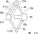
Fig. 1 is the vertical view of basic comprising of the transfer device of expression the 1st embodiment of the present invention, and Fig. 2 is the longitudinal section of the basic comprising of this transfer device of expression.
As shown in Fig. 1 and Fig. 2, the transfer device 1 of present embodiment comprises erects the 1st driving shaft 1a, the 2nd driving shaft 1b and the 3rd driving shaft 1c that is provided with respectively from the concentric shape of central side ground, to these the 1st~the 3rd driving shaft 1a~1c, transmit the rotary power of driving mechanism 6 described later respectively, rotation separately is controlled.
On the upper end of the upper end of the upper end of the 1st driving shaft 1a, the 2nd driving shaft 1b, the 3rd driving shaft 1c, installing and fixing the 1st arm the 2, the 2nd arm the 3, the 3rd arm 4 with level respectively.
Moreover the 1st~the 3rd driving shaft 1a~1c can move by in the vertical direction by vertical travel mechanism 11 described later.
In the present embodiment, be provided with the moveable arm assembly 14 of following explanation.
That is to say, in the moveable arm assembly 14 of present embodiment, slave arm 2a can be connected in the leading section of the 1st arm 2 that extends on linearity ground rotatably in horizontal plane, and slave arm 4a can be connected in the leading section of the 3rd arm 4 that extends on linearity ground rotatably in horizontal plane, and then these slave arms 2a can connect on concentric mutually shape ground rotatably with the relative fulcrum 8a of leading section of slave arm 4a.
In this occasion, slave arm 2a, 4a install rotating shaft 7a, the 7b that is located at base end part separately with for example unillustrated bearing, and in addition, slave arm 2a installs with for example unillustrated bearing with the relative fulcrum 8a of leading section of slave arm 4a.
The fixing platform 9a that supports on fulcrum 8a on this support platform 9a, supports platform 9a all the time to the posture ground of telescopic moving direction keeping parallelism, and for example special known ability of posture control 13a of mechanism shown in the 2002-200584 communique that opens is installed.
On this support platform 9a, the 1st carriage (the 1st handover portion) 10a that is used for placing as for example wafer of transferring thing is installed.
So, in the present embodiment, constitute the 1st connecting rod (the 1st linkage) 12a of parallel four-bar linkage structure by the 1st arm the 2, the 3rd arm 4, slave arm 2a, slave arm 4a.
Moreover, on this 1st connecting rod 12a, cross the state (hereinafter referred to as the dead-centre position) of 180 ° of the open-angles of the 1st arm 2 and the 3rd arm 4, support platform 9a and the 1st carriage 10a to be provided with and be used for passing through the 5a of mechanism by the 1st dead-centre position described later on the rotary middle spindle of the 1st~the 3rd driving shaft 1a~1c.
On the other hand, the 2nd arm 3 is provided with than its long horizontal wrist 30a and forms roughly コ font with the vertical wrist 30b of in the vertical direction extension, so that above-mentioned the 1st arm 2 does not contact (interference) with slave arm 2a, and then be in the position above the slave arm 2a on the 30c of the portion that returns of the 2nd arm 3 and in horizontal plane, connecting slave arm 3a rotatably.
In addition, base end part place at above-mentioned slave arm 4a, the slave arm 4b that linearity ground extends is in the horizontal plane above it non-contiguously with support platform 9a with the 1st arm 2 and is being connected rotatably, and then this slave arm 4b can connect on concentric mutually shape ground rotatably with the relative fulcrum 8a of leading section of above-mentioned slave arm 3a.
Here, slave arm 3a, 4b install rotating shaft 7c, the 7d that is located at base end part separately with for example unillustrated bearing.
In addition, as one man locate at the center of the rotating shaft 7d of the center of the rotating shaft 7b of slave arm 4a and slave arm 4b.
And then slave arm 3a also is to have adopted for example unillustrated bearing with being connected of leading section of slave arm 4b.
The 2nd carriage 10b that is used for placing as for example wafer of transferring thing is installed on this support platform 9b.
So, in the present embodiment, constitute the 2nd connecting rod (the 2nd linkage) 12b of the parallel four-bar linkage structure of the 2nd carriage 10b with the top that is positioned at above-mentioned the 1st carriage 10a by the 2nd arm the 3, the 3rd arm 4, slave arm 3a, slave arm 4b.
And, though these the 1st and the 2nd connecting rod 12a, 12b use the 3rd arm 4 jointly, by above-mentioned formation, separately the 1st with the moving of the 2nd carriage 10a, 10b when do not contact (interference) mutually.
In addition, on the 2nd connecting rod 12b, be provided with the state of 180 ° of the open-angles of crossing the 2nd arm 3 and the 3rd arm 4, support platform 9b and the 2nd carriage 10b to be used for the 2nd dead-centre position described later of the rotation centerline by the 1st~the 3rd driving shaft 1a~1c and pass through the 5b of mechanism.
Moreover, in the present embodiment, the brachium (length between rotating shaft) of the 1st arm the 2, the 2nd arm the 3, the 3rd arm 4, slave arm 2a, slave arm 3a, slave arm 4a, slave arm 4b be taken as all become same.
Fig. 3 is the vertical view of concrete formation of the transfer device of expression present embodiment, and Fig. 4 is the longitudinal section of the formation of this transfer device of expression, and Fig. 5 (a) is the key diagram of the dead-centre position of this transfer device of expression by the action of mechanism (b).
As shown in Figure 4, the transfer device 1 of present embodiment is that above-mentioned moveable arm assembly 14 is disposed at the bottom in the vacuum tank 20, and the 1st~the 3rd driving shaft 1a~1c is contained in the main part 15 that is located at vacuum tank 20 belows.
Here, main part 15 has the mounting flange 37 of the bottom that is installed on vacuum tank 20, bottom at this mounting flange 37, one end of the bellows 36 of the snake abdomen shape that can stretch is installed airtightly, housing 61 is installed on the other end of this bellows 36 airtightly, and then is fixing shell 62a, 62b, 62c in the bottom of housing 61.
In addition, on mounting flange 37, to vertical direction several for example pillars 38 of linear steering device and so on double as guide rail are installed, housing 61 constitutes along pillar 38 by for example linear sleeve and so on slide mechanism 39 up and down with shell 62a, 62b, 62c.
In the bottom of pillar 38 support substrate 40 is installed.And, by the driving force of directly employing motor 51 of the assigned position that is located at support substrate 40, be installed on ball-screw 52 rotations of the ball-screw nut 53 on the shell 62a and make main part 15 liftings.
On the other hand, between the 1st driving shaft 1a and the 2nd driving shaft 1b, between the 2nd driving shaft 1b and the 3rd driving shaft 1c, between the 3rd driving shaft and the housing 61, disposing respectively and connecting each other usefulness airtightly sliding freely, for example the sealing mechanism 63a, 63b, the 63c that form by magnetic fluid, O shape circle, Wilson seal etc.
Next, just rotation is controlled the driving mechanism 6 of the 1st~the 3rd driving shaft 1a~1c and the 1st and the 2nd connecting rod 12a, 12b is described to the vertical travel mechanism 11 that vertical direction moves usefulness.
The driving mechanism 6 of present embodiment has following formation with vertical travel mechanism 11.
As shown in Figure 4, in the bottom of the 1st, the 2nd, the 3rd driving shaft 1a, 1b, 1c, sensor target 33a, 33b, 33c that the anglec of rotation of each driving shaft 1a~1c of permanent magnet 32a, 32b, 32c and detection is used are installed respectively.
These permanent magnets 32a, 32b, 32c are made of monomer or a plurality of magnetic respectively.
In addition, sensor target 33a, 33b, 33c should be with disc-shape or drums, cross over to form in its wholecircle week and give detector 35a described later, 35b, 35c, perhaps, form for example figure of narrow slit shape of the variation of giving optics and so on changes of magnetic field and so on jog for example.
On the other hand, on the inwall of shell 62a, 62b, 62c, with above-mentioned permanent magnet 32a, 32b, 32c magnetic on solenoid 34a, 34b, 34c are installed on the position of the best of combining.
Here, solenoid 34a, 34b, 34c constitute based on the rotate instruction from control instruction device 54 and supply with predetermined electric current from rotation control mechanism 55.
In addition, on the inwall of shell 62a, 62b, 62c, on position, detector 35a, 35b, 35c are installed respectively to sensor target 33a, 33b, 33c the best.
And the feedback information of the anglec of rotation that constitutes the 1st~the 3rd driving shaft 1a~1c that will be detected by detector 35a, 35b, 35c is correctly controlled the rotation of the 1st~the 3rd driving shaft 1a~1c to rotation control mechanism 55.
In having the present embodiment of this formation, as shown in Figure 4, if send rotate instruction to rotation control mechanism 55 by control instruction device 54, then supply with electric current to solenoid 34a, 34b, 34c by rotation control mechanism 55, masterpiece is used for permanent magnet 32a, 32b, the 32c of combination on the magnetic, the 1st~the 3rd driving shaft 1a~1c rotation.
At this moment, because sensor target 33a, 33b, 33c also rotate in the 1st~the 3rd driving shaft 1a~1c rotation, so the feedback information of the anglec of rotation of each driving shaft 1a~1c that will be detected by detector 36a, 36b, 36c is controlled the rotation of the 1st~the 3rd driving shaft 1a~1c whereby to rotation control mechanism 55.
In addition,, directly employ motor 51 actions,, make housing 61 and shell 62a, 62b, 62c along pillar 38 liftings along with stretching of bellows 36 by making in the occasion that makes the 1st~the 3rd driving shaft 1a~1c to the vertical direction action.
At this moment, because the 1st~the 3rd driving shaft 1a~1c and housing 61 1 liftings, so be installed on the change in location of vertical direction of the moveable arm assembly 14 of the 1st~the 3rd driving shaft 1a~1c.
Next, describe with regard to dead-centre position shown in Figure 2 formation by the 5a of mechanism, 5b.
As shown in Fig. 3 and Fig. 4, in the present embodiment, the 1st drive pulley 21a is fixed in above-mentioned the 1st driving shaft 1a, and make center line as one man fixing at bottom the 1st driven pulley 21b of the rotating shaft 17 of the hollow of the base end part that is fixed in slave arm 4a and the rotating shaft 17 of hollow, the rotating shaft 17 of hollow constitutes around rotating shaft 7d and rotates.And then, between these the 1st drive pulley 21a and the 1st driven pulley 21b around hanging belt 22a.
And, by these the 1st drive pulleys 21a, the 1st driven pulley 21b, belt 22a, constitute and make the open-angle of the 1st arm 2 and the 3rd arm 4 cross 180 °, make and support the 1st dead-centre position of using on platform 9a and the concentric rotating shaft of the 1st carriage 10a to pass through the 5a of mechanism by the 1st~the 3rd driving shaft 1a~1c.
On the other hand, the 2nd drive pulley 21c is fixed in the upper end of the 2nd driving shaft 1b, and the 2nd driven pulley 21d make the center line unanimity in the rotating shaft 7d of slave arm 4d fix, between these the 2nd drive pulley 21c and the 2nd driven pulley 21d around hanging belt 22b.
And, by these the 2nd drive pulleys 21c, the 2nd driven pulley 21d, belt 22b, constitute and make the open-angle of the 2nd arm 3 and the 3rd arm 4 cross 180 ° state, make and support platform 9b and the 2nd carriage 10b to pass through the 5b of mechanism by the 2nd dead-centre position of using on the 1st~the 3rd driving shaft 1a~1c rotation centerline.
Moreover, occasion in present embodiment, the 1st dead-centre position is identical with the diameter of the 1st driven pulley 21b by the 1st drive pulley 21a of the 5a of mechanism, and in addition, the 2nd dead-centre position is identical with the diameter of the 2nd driven pulley 21d by the 2nd drive pulley 21c of the 5b of mechanism.
In addition, also can be taken as the 1st drive pulley 21a, the 1st driven pulley 21b, the 2nd drive pulley 21c, all diameters of the 2nd drive pulley 21d identical.
Below, with regard to the action of the dead-centre position in the present embodiment, (b) describe with Fig. 5 (a) by mechanism.
Moreover, Fig. 5 (a) (b) in, for the purpose of the convenience that illustrates, represent the 1st connecting rod 12a and the 2nd connecting rod 12b respectively.
At first, be that example illustrates the action of the 1st dead-centre position by the 5a of mechanism with the 1st connecting rod 12a that is in the retracted position by the occasion that the dead-centre position moves to extended position.
If make the 1st, the 3rd driving shaft 1a, 1c rotate same angle (in Fig. 5 (a) on the rightabout mutually, make the 1st driving shaft 1a (the 1st arm 2) CW (clockwise direction) rotation, make the 3rd driving shaft 1c (the 3rd arm 4) CCW (counterclockwise) rotation), then the open-angle at the 1st arm 2 and the 3rd arm 4 becomes 180 ° the moment, and the 1st connecting rod 12a becomes the dead-centre position state.
Here, if make the 1st driving shaft 1a on the CW direction, rotate the angle θ of regulation, then the 1st driving shaft 1a is become with one heart also anglec of rotation θ on the CW direction of the 1st drive pulley 21a that installs.
Therewith concurrently, because the 3rd driving shaft 1c anglec of rotation θ on the CCW direction, so the 1st drive pulley 21a that sees from the 3rd arm 4 relative is rotated in 2 θ that CW direction upper angle becomes twice.
Because rotatablely moving of this 1st drive pulley 21a transmitted to the 1st driven pulley 21b via belt 22a, so also relative the 3rd arm 4 of the 1st driven pulley 21b relative rotation angle 2 θ on the CW direction.
So, if make the 1st, the 3rd driving shaft 1a, 1c rotation, then the 1st driven pulley 21b also rotates, because relative the 3rd arm of slave arm 4a 4 rotations, so the 1st connecting rod 12a deviates from the dead-centre position state, the 1st carriage 10a and support platform 9a just cross the 1st, the 2nd, the 3rd driving shaft 1a, the common concentric rotating shaft of 1b, 1c moves.
Moreover, when making the 1st connecting rod 12a that is in extended position get back to the retracted position, on antipodal direction, carry out action described above by the dead-centre position.
Next, be that example illustrates the action of the 2nd dead-centre position by the 5b of mechanism with the 2nd connecting rod 12b that is in the retracted position by the occasion that the dead-centre position moves to extended position.
If make the 2nd, the 3rd driving shaft 1b, 1c rotate same angle (in Fig. 5 (b) on the rightabout mutually, the 2nd driving shaft 1b (the 2nd arm 3) is rotated along the CW direction, make the 3rd driving shaft 1c (the 3rd arm 4) along the rotation of CCW direction), then the open-angle at the 2nd arm 3 and the 3rd arm 4 becomes 180 ° the moment, and the 2nd connecting rod 12b becomes the dead-centre position state.
Here, if make the 2nd driving shaft 1b rotate the angle θ of regulation on the CW direction, the 2nd drive pulley 21c that then relative the 2nd driving shaft 1b installs with one heart is anglec of rotation θ on the CW direction also.
Therewith concurrently, because the 3rd driving shaft 1c anglec of rotation θ on the CCW direction, so the 2nd drive pulley 21c that sees from the 3rd arm 4 relative is rotated in 2 θ that CW direction upper angle becomes twice.
Because rotatablely moving of this 2nd drive pulley 21c transmitted to the 2nd driven pulley 21d via belt 22b, so also relative the 3rd arm 4 of the 2nd driven pulley 21d relative rotation angle 2 θ on the CW direction.
So, if make the 2nd, the 3rd driving shaft 1b, 1c rotation, then the 2nd driven pulley 21d also rotates, because relative the 3rd arm of slave arm 4b 4 rotations, so the 2nd connecting rod 12b deviates from the dead-centre position state, the 2nd carriage 10b and support platform 9b just cross the 1st, the 2nd, the 3rd driving shaft 1a, the common concentric rotating shaft of 1b, 1c moves.
Moreover, when making the 2nd connecting rod 12b that is in extended position get back to the retracted position, on antipodal direction, carry out action described above by the dead-centre position.
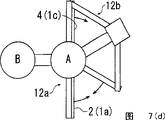
Next, with Fig. 6~Fig. 8,, be that example describes with occasion the wafer B of the processing in the process chamber (not shown) that is in semiconductor-fabricating device and untreated wafer A replacing with regard to the action of the transfer device of present embodiment.
Here, considering has untreated wafer A on the 2nd carriage 10b, do not have the state of wafer on the 1st carriage 10a.
As shown in Fig. 6 (a), at first, the 1st and the 2nd connecting rod 12a, 12b are placed the retracted position state.At this moment, the 1st and the 2nd connecting rod 10a, 10b are opposed on above-below direction, and wafer A is near the position of concentric rotating shaft of the 1st~the 3rd driving shaft 1a~1c.
In this state, if make the 1st~the 3rd driving shaft 1a~1c rotate same angle to same direction simultaneously, then since the relative position of the 1st~3 arm 2~4 do not change, so moveable arm assembly 14 is that the center rotates with the state that contracts in keeping with the concentric rotating shaft of the 1st~the 3rd driving shaft 1a~1c totally.As a result, the wafer B that can make two carriage 10a, 10b and be in the processing in the process chamber aligns (Fig. 6 (a)).
Moreover, though when original moveable arm assembly 14 was in the retracted position state, the 1st connecting rod 12a became the state that overlaps with the 2nd connecting rod 12b, for the purpose of the convenience that illustrates, a little represents in the drawings with staggering.
Then, if though make the 1st, the 3rd driving shaft 1a, 1c rotate same angle (in Fig. 6 (a) to mutual rightabout, make the rotation of the 1st driving shaft 1a (the 1st arm 2) CW direction, make the rotation of the 3rd driving shaft 1c (the 3rd arm 4) CCW direction), then the 1st connecting rod 12a becomes dead-centre position state (Fig. 6 (b)), but effect the 1st connecting rod 12a by the 5a of mechanism deviates from the dead-centre position state by above-mentioned the 1st dead-centre position, the 1st carriage 10a and support platform 9a to cross the common concentric rotating shaft of the 1st~the 3rd driving shaft 1a~1c and move.
And if then make the 1st, the 3rd driving shaft 1a, 1c continue rotation, then the 1st carriage 10a arrives extended position (Fig. 6 (c)).
In this state, because the 1st carriage 10a is positioned at the lower side of the wafer B that handled, institute is so that vertically travel mechanism's 11 actions, make the 1st~the 3rd driving shaft 1a~1c move and the moveable arm assembly 14 that comprises the 1st connecting rod 12a is totally moved up, accept the wafer B that handled by the 1st carriage 10a to vertical top.
Then, if though in order to make the 1st carriage 10a that is in extended position get back to the retracted position, make the 1st on the contrary with previous action, the 3rd driving shaft 1a, 1c is rotating same angle (in Fig. 6 (c) on the rightabout mutually, make the rotation of the 1st driving shaft 1a CCW direction, make the rotation of the 3rd driving shaft 1c CW direction), then the 1st connecting rod 12a becomes dead-centre position state (Fig. 7 (d)) once more, but effect the 1st connecting rod 12a by the 5a of mechanism deviates from the dead-centre position state by the 1st dead-centre position, the 1st carriage 10a and support platform 9a to cross the common concentric rotating shaft of the 1st~the 3rd driving shaft 1a~1c and move.
And if then make the 1st, the 3rd driving shaft 1a, 1c continue the rotation, then the 1st carriage 10a gets back to the retracted position (Fig. 7 (e)) of the 1st connecting rod 12a.
In this state, the 1st and the 2nd carriage 10a, 10b on above-below direction over against.And two plates A, B also with on the above-below direction over against state be positioned near the concentric rotating shaft of the 1st~the 3rd driving shaft 1a~1c.
Moreover, if with the above-mentioned a series of action of hereto the 1st, the 3rd driving shaft 1a, 1c concurrently, make the 2nd driving shaft 1b (the 2nd arm 3) to rotating same angle with the same direction of the 3rd driving shaft 1c, then the concentric rotating shaft with the 1st~the 3rd driving shaft 1a~1c is center rotation (Fig. 6 (b)~Fig. 7 (e)) because the 2nd connecting rod 12b keeps the retracted position state, so the wafer A on the 2nd carriage 10b does not move and rotates near the concentric rotating shaft of the 1st~the 3rd driving shaft 1a~1c, can not collide the works of transfer device periphery.
Then, if though make the 2nd, the 3rd driving shaft 1b, 1c rotate same angle (in Fig. 7 (e) on the rightabout mutually, make the rotation of the 2nd driving shaft 1b (the 2nd arm 3) CW direction, make the rotation of the 3rd driving shaft 1c (the 3rd arm 4) CCW direction), then the 2nd connecting rod 12b becomes dead-centre position state (Fig. 7 (f)), but effect the 2nd connecting rod 12b by the 5b of mechanism deviates from the dead-centre position state by the 2nd dead-centre position, the 2nd carriage 10b and support platform 9b to cross the concentric rotating shaft of the 1st~the 3rd driving shaft 1a~1c and move.
And if then make the 2nd, the 3rd driving shaft 1b, 1c continue the rotation, then the 2nd carriage 10b and wafer A arrive the extended position (Fig. 8 (g)) of the 2nd connecting rod 12b.
In this state, make 11 actions of vertical travel mechanism, the 1st~the 3rd driving shaft 1a~1c is moved straight down and the untreated wafer A on the 2nd carriage 10b is joined to unillustrated treating apparatus.
Then, if though in order to make the 2nd carriage 10b that is in extended position get back to the retracted position, opposite with previous action, make the 2nd, the 3rd driving shaft 1b, 1c is rotating same angle (in Fig. 8 (g) on the rightabout mutually, make the rotation of the 2nd driving shaft 1b (the 2nd arm 3) CCW direction, make the rotation of the 3rd driving shaft 1c (the 3rd arm 4) CW direction), then the 2nd connecting rod 12b becomes dead-centre position state (Fig. 8 (h)) once more, but effect the 2nd connecting rod 12b by the 5b of mechanism deviates from the dead-centre position state by the 2nd dead-centre position, the 2nd carriage 10b and support platform 9b to cross the concentric rotating shaft of the 1st~the 3rd driving shaft 1a~1c and move.
And if then make the 2nd, the 3rd driving shaft 1b, 1c continue the rotation, then the 2nd carriage 10b gets back to retracted position (Fig. 8 (f)).
In this state, the 1st and the 2nd carriage 10a, 10b align on above-below direction, and wafer B is near the position of concentric rotating shaft of the 1st~the 3rd driving shaft 1a~1c in addition.
Moreover, if since with the above-mentioned a series of action of hereto the 2nd, the 3rd driving shaft 1b, 1c concurrently, make the 1st driving shaft 1a (the 1st arm 2) to rotating same angle with the same direction of the 3rd driving shaft 1c, then the 1st connecting rod 12a keeps the retracted position state and is center rotation (Fig. 7 (f)~Fig. 8 (i)) with the 1st~the 3rd driving shaft 1a~1c, so the wafer B on the 1st carriage 10a does not rotate movably, can not collide the works of transfer device periphery near the concentric rotating shaft of the 1st~the 3rd driving shaft 1a~1c.
So, can at short notice the wafer B of the processing in the process chamber that is in semiconductor-fabricating device and untreated wafer A be changed on the efficient highland.
Next, the 1st connecting rod 12a and the 2nd connecting rod 12b are described respectively with Fig. 9 and Figure 10 from the overseas method that moves in rotatable zone of rotatable area.
This action is after just starting transfer device 1, and occasion that the 1st connecting rod 12a and the 2nd connecting rod 12b are placed its retracted position state (for example state shown in Fig. 6 (a)) etc. is necessary respectively.
Fig. 9 (a)~(c) and Figure 10 (a) (b) in, represent for example position in the vacuum next door of semiconductor-fabricating device with the circle shown in the single-point line, the 1st connecting rod 12a and the 2nd connecting rod 12b become when being positioned at this circle and can rotate.
Here, as shown in Fig. 9 (a), consider that the part of the 1st connecting rod 12a and the 2nd connecting rod 12b is positioned at above-mentioned rotatable extra-regional occasion after just starting transfer device 1.
In this occasion, at first, in Fig. 9 (a), make the rotation of the 1st driving shaft 1a (the 1st arm 2) CW direction, make the rotation of the 2nd driving shaft 1b (the 2nd arm 3) CCW direction, make the 3rd driving shaft 1c (the 3rd arm 4) CCW direction rotate same angle.
Whereby, support platform 9a and the 1st carriage 10a to retreat along the straight line 16a that becomes about the symmetry axis of the 1st connecting rod 12a line symmetry, support platform 9b and the 2nd carriage 10b retreat along the straight line 16b that becomes about the symmetry axis of the 2nd connecting rod 12b line symmetry.
Then, if make the 1st~the 3rd driving shaft 1a~1c continue rotation to same direction same as before, then the 2nd connecting rod 12b passes through dead-centre position (Fig. 9 (b)) by the 2nd dead-centre position by the effect of the 5b of mechanism, arrives rotatable retracted position (Fig. 9 (c)).
And then, arrive the moment of the retracted position that can rotate at the 2nd connecting rod 12b, the direction of rotation of the 2nd driving shaft 1b is switched to the CW direction from the CCW direction, make the rotation of the 1st driving shaft 1a CW direction respectively, make the rotation of the 2nd driving shaft 1b CW direction, make the 3rd driving shaft 1cC CW direction rotate same angle.
Whereby, though because the 1st connecting rod 12a passes through the dead-centre position by the 1st dead-centre position by the effect of the 5a of mechanism, so support that platform 9a and the 1st carriage 10a continue to retreat along straight line 16a, but because the 1st driving shaft 1a and the 2nd driving shaft 1b rotate same angle to same direction, the concentric rotating shaft so the 2nd carriage 12b keeps the retracted position state with the 1st~the 3rd driving shaft 1a~1c is center rotation (Figure 10 (d)).
And then if make the 1st~the 3rd driving shaft 1a~1c continue rotation same as before, then the 1st connecting rod 12a arrives retracted position state (Figure 10 (e)).In this state, the 1st and the 2nd carriage 10a, 10b align on above-below direction.
By carrying out this action, the 1st connecting rod 12a and the 2nd connecting rod 12b are moved respectively in rotatable zone from rotatable area is overseas.
Moreover the occasion opposite with Fig. 9 (a) with the position relation of the 2nd connecting rod 12b at the 1st connecting rod 12a also is similarly to make the 1st~the 3rd driving shaft 1a~1c rotation just passable with aforesaid action.
As previously discussed, according to present embodiment, then because the wafer that is on the 1st and the 2nd carriage 10a, the 10b etc. is moved near the concentric rotating shaft of the 1st~the 3rd driving shaft 1a~1c, even the occasion of rotation so support big wafer etc. at retracted position place, compared with prior art also radius of turn can be reduced, the densification of device can be sought whereby.
In addition according to present embodiment, then compared with prior art, even accelerate the rotary speed of transfer device 1, the centrifugal force that acts on wafer etc. does not also strengthen, and the wafer on the 1st and the 2nd carriage 10a, 10b when the rotation etc. does not cause position deviation.
In addition, according to present embodiment, then because the revolving force that takes place because of the effect of the magnetic of solenoid 34a~34c and permanent magnet 32a~32c directly correctly is delivered to the 1st and the 2nd connecting rod 12a, 12b via the 1st~the 3rd driving shaft 1a~1c, so in the just commentaries on classics of motor, counter-rotating, in rotation, do not produce hysteresis, can be transplanted on correct position to wafer on the 1st and the 2nd carriage 10a, the 10b etc.
In addition, in the present embodiment, control the rotation of the 1st~the 3rd driving shaft 1a~1c because of the information of the anglec of rotation of the 1st~the 3rd driving shaft 1a~1c that feedback is detected by test section 35a, 35b, 35c, so can be transplanted on correct position to the wafer on the 1st and the 2nd carriage 10a, the 10b etc.
And, according to present embodiment, then because constituent part is few, thus can suppress manufacturing expense very lowly, and because sliding part is few, so can suppress maintenance cost very lowly.And then, do not need reductor etc., do not transmit the consumption of power, thus,,, can suppress manufacturing expense very lowly, and can reduce the size of transfer device 1 so the size of motor reduces because just enough with the little person of generation torque of motor.
Figure 11 is the vertical view of formation of the transfer device of expression the 2nd embodiment of the present invention, and Figure 12 is the longitudinal section of the formation of this transfer device of expression, and Figure 13 (a) is the key diagram of the dead-centre position of this transfer device of expression by the action of mechanism (b).Below, give same label and omit its detailed description at the part corresponding with above-mentioned embodiment.
As shown in Figure 11, it is longer than the brachium of the 1st connecting rod 12a that the transfer device 1A of present embodiment is taken as the brachium of the 2nd connecting rod 12b.
In the present embodiment, constitute in the middle of the 1st~the 3rd arm 2~4, the length of the 2nd arm 3 and the 3rd arm 4 is longer than the 1st arm 2, and then the length of corresponding each slave arm 3a, 4b is longer than slave arm 2a, 4a.
And in the midfield part of the 2nd arm 3 that is driven by the 2nd driving shaft 1b, slave arm 4a is that the mode that the center rotates in horizontal plane links with the rotating shaft 7b that is located at its base end part.And then this slave arm 2a and slave arm 4a and above-mentioned embodiment are same, and leading section separately supports the fulcrum 8a of platform 9a to connect into shape ground rotation with one heart mutually relatively, constitutes the 1st connecting rod 12a whereby.
On the other hand, with regard to the 2nd connecting rod 12b, have the basic comprising same with the occasion of above-mentioned embodiment.
That is to say, connecting into slave arm 4b on the leading section of the 2nd arm 3 is that the center can rotate in horizontal plane with the rotating shaft 7b that is located at its base end part, and connecting into slave arm 3a at the leading section of the 3rd arm 4 is that the center can rotate in horizontal plane with the rotating shaft 7c that is located at its base end part, and then the fulcrum 8b that the leading section of these slave arms 4b and slave arm 3a connects into supporting platform 9b can rotate on concentric mutually shape ground.
In this occasion, the 2nd arm 3 is not contacted (interference) with the length setting Cheng Yudi 1 connecting rod 12a of the 3rd arm 4, and the length of lengthening rotating shaft 7c, 7d, become the formation that slave arm 3a, 4b are positioned at the top of supporting platform 9a.
And, supporting that above-mentioned the 2nd carriage 10b is installed on the platform 9b, whereby, constitute the 2nd connecting rod 12b that comprises the 2nd carriage 10b that is positioned at its top mutually uninterruptedly with the 1st carriage 10a.
And then, occasion in present embodiment, drive pulley 25 is fixed on the 2nd driving shaft 1b, and make the center line unanimity in the rotating shaft 7a of slave arm 2a fix the 1st driven pulley 21b, between these drive pulleys 25 and the 1st driven pulley 21b around hanging belt 22a.
And, by these drive pulleys the 25, the 1st driven pulley 21b, belt 22a, constitute above-mentioned the 1st same dead-centre position by the 5a of mechanism.
In addition, make the center line unanimity in the rotating shaft 7c of slave arm 3a fix the 2nd driven pulley 21d, between this 2nd driven pulley 21d and above-mentioned drive pulley 25 around hanging belt 22b, by these drive pulleys the 25, the 2nd driven pulley 21d, belt 22b, constitute above-mentioned the 2nd same dead-centre position by the 5b of mechanism.
At first, be that example illustrates the action of the 1st dead-centre position by the 5a of mechanism with the 1st connecting rod 12a that is in the retracted position by the occasion that the dead-centre position moves to extended position.
If make the 1st, the 2nd driving shaft 1a, 1b rotate same angle (in Figure 13 (a) on the rightabout mutually, make the rotation of the 1st driving shaft 1a (the 1st arm 2) CW direction, make the rotation of the 2nd driving shaft 1b (the 2nd arm 3) CCW direction), then the open-angle at the 1st arm 2 and the 2nd arm 3 becomes 180 ° the moment, and the 1st connecting rod 12a becomes the dead-centre position state.
Here, if make the 2nd driving shaft 1b anglec of rotation θ on the CCW direction, then the 2nd driving shaft 1b is become with one heart also anglec of rotation θ on the CCW direction of the drive pulley 25 installed.
Therewith concurrently, because the 1st driving shaft 1a anglec of rotation θ on the CW direction, so the drive pulley of seeing from the 1st arm 2 25 relative is rotated in 2 θ that CCW direction upper angle becomes twice.
Because rotatablely moving of this drive pulley 25 transmitted to the 1st driven pulley 21b via belt 22a, so also relative the 1st arm 2 of the 1st driven pulley 21b relative rotation angle 2 θ on the CCW direction.
So, if make the 1st, the 2nd driving shaft 1a, 1b rotation, then the 1st driven pulley 21b also rotates, because relative the 1st arm of slave arm 2a 2 rotations, so the 1st connecting rod 12a deviates from the dead-centre position state, the 1st carriage 10a and support platform 9a just cross the 1st, the 2nd, the 3rd driving shaft 1a, the common concentric rotating shaft of 1b, 1c moves.
Moreover, when making the 1st connecting rod 12a that is in extended position get back to the retracted position, on antipodal direction, carry out action described above by the dead-centre position.
Next, be that example illustrates the action of the 2nd dead-centre position by the 5b of mechanism with the 2nd connecting rod 12b that is in the retracted position by the occasion that the dead-centre position moves to extended position.
If make the 2nd, the 3rd driving shaft 1b, 1c rotate same angle (in Figure 13 (b) on the rightabout mutually, make the rotation of the 3rd driving shaft 1c (the 3rd arm 4) CW direction, make the rotation of the 2nd driving shaft 1b (the 2nd arm 3) CCW direction), then the open-angle at the 2nd arm 3 and the 3rd arm 4 becomes 180 ° the moment, and the 2nd connecting rod 12b becomes the dead-centre position state.
Here, if make the 2nd driving shaft 1b anglec of rotation θ on the CCW direction, the drive pulley 25 that then relative the 2nd driving shaft 1b installs with one heart is anglec of rotation θ on the CCW direction also.
Therewith concurrently, because the 3rd driving shaft 1c anglec of rotation θ on the CW direction, so the drive pulley of seeing from the 3rd arm 4 25 relative is rotated in 2 θ that the CCW orientation angle becomes twice.
Because rotatablely moving of this drive pulley 25 transmitted to the 2nd driven pulley 21d via belt 22b, so also relative the 3rd arm 4 of the 2nd driven pulley 21d relative rotation angle 2 θ on the CCW direction.
So, if make the 2nd, the 3rd driving shaft 1b, 1c rotation, then the 2nd driven pulley 21d also rotates, because relative the 3rd arm of slave arm 3a 4 rotations, so the 2nd connecting rod 12b deviates from the dead-centre position state, the 2nd carriage 10b and support platform 9b just cross the 1st, the 2nd, the 3rd driving shaft 1a, the common concentric rotating shaft of 1b, 1c moves.
Moreover, when making the 2nd connecting rod 12b that is in extended position get back to the retracted position, on antipodal direction, carry out action described above by the dead-centre position.
According to present embodiment with this formation, then except with the same effect of above-mentioned embodiment, the rotating shaft 7a absolute construction that becomes different from the embodiment described above that rotating shaft 7c that is installed owing to the 1st driven pulley 21b and the 2nd driven pulley 21d are installed, so assembling operation is simple, exist the such advantage of assembling operation time shortening.Since with regard to other formation and action effect with regard to above-mentioned embodiment be same, so omit its detailed description.
Figure 14 is the vertical view of roughly representing to have according to the formation of the embodiment of the vacuum treatment installation of transfer device of the present invention.
As shown in Figure 14, in semiconductor-fabricating device 40 as one of vacuum treatment installation of the present invention example, around the set handover chamber 41 of above-mentioned transfer device 1, disposing three process chambers 42,43,44 that can process processing side by side, be used for moving into the immigration chamber 45 of wafer, and be used for shifting out wafer shift out chamber 46.
These process chambers 42~44 move into chamber 45, shift out chamber 46 and be connected on the unillustrated vacuum pumping system, respectively and transfer between the chamber 41 and be provided with isolating valve 42a~46a.
Take out by above-mentioned transfer device 1 and to be contained in the untreated wafer 50a that moves into chamber 45, keep it and be transplanted on for example process chamber 42.
At this moment, transfer device 1 is collected the wafer 50b that handled by carrying out above-mentioned action from process chamber 42, it to another for example process chamber 43 transfer.
Below similarly, with transfer device 1 at process chamber 42~44, move into chamber 45, shift out 46 in chamber, carry out untreated wafer 50a and the handing-over of the wafer 50b that handled.
According to present embodiment with this formation, then can the generator overall little semiconductor-fabricating device of area that is provided with.
Moreover, the invention is not restricted to above-mentioned embodiment, can carry out all changes.
For example, though in the above-described embodiment,, use by parallel four-bar linkage structure and form, the invention is not restricted to this, also can adopt other linkages as the 1st and the 2nd linkage.
But, from the minor diameterization of radius of turn and the viewpoint of subduing of part number, preferably use and form by above-mentioned parallel four-bar linkage structure.
And then, though in the dead-centre position of above-mentioned embodiment by in the mechanism, use belt pulley and belt, also can replace belt and use gear, also can use chain and sprocket wheel in addition.
Claims (8)
1. transfer device has:
1st, the 2nd and the 3rd driving shaft is configured on the concentric rotating shaft of regulation with one heart shape, and rotation separately can be controlled;
1st, the 2nd and the 3rd actuating arm is separately fixed on aforementioned the 1st~the 3rd driving shaft, and axle base is identical;
The 1st linkage has the 1st and the 3rd actuating arm in aforementioned the 1st~the 3rd actuating arm and is attached at a pair of slave arm on the 1st and the 3rd actuating arm, links to have on this slave arm to be used for to transferring the 1st handover portion that object is transferred;
The 2nd linkage has the 2nd and the 3rd actuating arm in aforementioned the 1st~the 3rd actuating arm and is attached at a pair of slave arm on the 1st and the 3rd actuating arm, links to have on this slave arm to be used for to transferring the 2nd handover portion that object is transferred;
The the aforementioned the 1st and the 2nd linkage is made of the parallel four-bar linkage of action in the horizontal direction, the open-angle that has an a pair of arm of the 1st and the 2nd linkage become 180 °, pass through mechanism by the dead-centre position of dead-centre position.
2. the described transfer device of claim 1,
Also have and make the aforementioned the 1st and the 2nd linkage to vertical travel mechanism that vertical direction moves.
3. the described transfer device of claim 1,
Also have driving mechanism, this driving mechanism comprises the permanent magnet on the position of the regulation that is disposed at aforementioned the 1st~the 3rd driving shaft respectively, with the electromagnetic stator that is provided with accordingly with aforementioned permanent magnet, the aforementioned electromagnetic stator is supplied with drive current based on the information of regulation.
4. the described transfer device of claim 1,
Also have driving mechanism, this driving mechanism comprises the angular transducer of the anglec of rotation that detects aforementioned the 1st~the 3rd driving shaft respectively, controls the rotation of aforementioned the 1st~the 3rd driving shaft based on resulting result in this angular transducer.
5. method of controlling transfer device,
Aforementioned transfer device has:
1st, the 2nd and the 3rd driving shaft is configured on the concentric rotating shaft of regulation with one heart shape, and rotation separately can be controlled;
1st, the 2nd and the 3rd actuating arm is separately fixed on aforementioned the 1st~the 3rd driving shaft, and axle base is identical;
The 1st linkage has the 1st and the 3rd actuating arm in aforementioned the 1st~the 3rd actuating arm and is attached at a pair of slave arm on the 1st and the 3rd actuating arm, links to have on this slave arm to be used for to transferring the 1st handover portion that object is transferred;
The 2nd linkage has the 2nd and the 3rd actuating arm in aforementioned the 1st~the 3rd actuating arm and is attached at a pair of slave arm on the 1st and the 3rd actuating arm, links to have on this slave arm to be used for to transferring the 2nd handover portion that object is transferred;
The the aforementioned the 1st and the 2nd linkage is made of the parallel four-bar linkage of action in the horizontal direction, the open-angle that has an a pair of arm of the 1st and the 2nd linkage become 180 °, pass through mechanism by the dead-centre position of dead-centre position;
This method may further comprise the steps: is that the same direction of middle mind-set is only rotated equal angles by making aforementioned the 1st~the 3rd actuating arm with aforementioned concentric rotating shaft, and making the aforementioned the 1st and the 2nd handover portion is the center rotation with aforementioned concentric rotating shaft.
6. the method for the described control transfer device of claim 5 may further comprise the steps:
A pair of actuating arm by making a side linkage in aforementioned the 1st linkage or the 2nd linkage is that the mutual rightabout of middle mind-set only rotates equal angles with aforementioned concentric rotating shaft, and making a pair of actuating arm of the opposing party's linkage is that the mutual equidirectional of middle mind-set only rotates equal angles with aforementioned concentric rotating shaft, and the direction of a certain direction by the straight line of aforementioned concentric rotating shaft in aforementioned the 1st handover portion or aforementioned the 2nd handover portion moved.
7. the method for the described control transfer device of claim 5 may further comprise the steps:
When the aforementioned the 1st and the 2nd handover portion is moved in rotatable zone,
A pair of actuating arm by making the aforementioned the 1st and the 2nd linkage respectively is that the center only rotates equal angles round about with aforementioned concentric rotating shaft, and the aforementioned the 1st and the 2nd handover portion is moved to the direction towards aforementioned rotatable zone,
In the moment in the aforementioned rotatable zone of some arrival of aforementioned the 1st handover portion or the 2nd handover portion, the a pair of actuating arm of the linkage by making the handover portion that comprises that this arrives rotatable zone is that middle mind-set equidirectional only rotates equal angles with aforementioned concentric rotating shaft, making this handover portion is the center rotation with aforementioned concentric rotating shaft, and
The a pair of actuating arm of the linkage by making the handover portion that comprises the aforementioned rotatable zone of no show respectively is that the center only rotates equal angles round about with aforementioned concentric rotating shaft, makes this handover portion continue to move to the direction towards aforementioned rotatable zone.
8. vacuum treatment installation has:
Transfer device, this transfer device has the 1st, the 2nd, with the 3rd driving shaft, the 1st, the 2nd, with the 3rd actuating arm, the 1st linkage, the 2nd linkage, the described the 1st, the 2nd, with the concentric shape of the 3rd driving shaft be configured on the concentric rotating shaft of regulation, rotation separately can be controlled, the described the 1st, the 2nd, be separately fixed on aforementioned the 1st~the 3rd driving shaft with the 3rd actuating arm, axle base is identical, described the 1st linkage has the 1st and the 3rd actuating arm in aforementioned the 1st~the 3rd actuating arm, with a pair of slave arm that is attached on the 1st and the 3rd actuating arm, on this slave arm, link to have and be used for transferring the 1st handover portion that object is transferred, described the 2nd linkage has the 2nd and the 3rd actuating arm in aforementioned the 1st~the 3rd actuating arm, with a pair of slave arm that is attached on the 1st and the 3rd actuating arm, on this slave arm, link to have and be used for transferring the 2nd handover portion that object is transferred, the the aforementioned the 1st and the 2nd linkage is made of the parallel four-bar linkage of action in the horizontal direction, the open-angle that has an a pair of arm of the 1st and the 2nd linkage becomes 180 °, mechanism is passed through in dead-centre position by the dead-centre position
Transfer chamber with aforementioned transfer device, and
Be communicated with aforementioned transfer chamber, handle the vacuum processing chamber of object with aforementioned transfer device handing-over.
Applications Claiming Priority (3)
| Application Number | Priority Date | Filing Date | Title |
|---|---|---|---|
| JP2004109683A JP4515133B2 (en) | 2004-04-02 | 2004-04-02 | Conveying apparatus, control method therefor, and vacuum processing apparatus |
| JP109683/2004 | 2004-04-02 | ||
| JP109683/04 | 2004-04-02 |
Publications (2)
| Publication Number | Publication Date |
|---|---|
| CN1676285A CN1676285A (en) | 2005-10-05 |
| CN100463783C true CN100463783C (en) | 2009-02-25 |
Family
ID=35049108
Family Applications (1)
| Application Number | Title | Priority Date | Filing Date |
|---|---|---|---|
| CNB200510062636XA Expired - Fee Related CN100463783C (en) | 2004-04-02 | 2005-04-01 | Transport apparatus, control method for the same, and vacuum processing system |
Country Status (5)
| Country | Link |
|---|---|
| US (1) | US7572093B2 (en) |
| JP (1) | JP4515133B2 (en) |
| KR (1) | KR101143287B1 (en) |
| CN (1) | CN100463783C (en) |
| TW (1) | TW200536689A (en) |
Families Citing this family (16)
| Publication number | Priority date | Publication date | Assignee | Title |
|---|---|---|---|---|
| US9117859B2 (en) * | 2006-08-31 | 2015-08-25 | Brooks Automation, Inc. | Compact processing apparatus |
| US8267636B2 (en) * | 2007-05-08 | 2012-09-18 | Brooks Automation, Inc. | Substrate transport apparatus |
| WO2008140093A1 (en) * | 2007-05-15 | 2008-11-20 | Ulvac, Inc. | Transfer apparatus, and vacuum treating apparatus |
| US8016542B2 (en) * | 2007-05-31 | 2011-09-13 | Applied Materials, Inc. | Methods and apparatus for extending the reach of a dual scara robot linkage |
| CN101689525B (en) * | 2008-01-31 | 2012-08-22 | 佳能安内华股份有限公司 | Vacuum transportation device, vacuum processing device and manufacturing method of display device |
| JP5150608B2 (en) * | 2009-11-20 | 2013-02-20 | 株式会社アルバック | Conveying device and vacuum device |
| WO2012023156A1 (en) * | 2010-08-17 | 2012-02-23 | キヤノンアネルバ株式会社 | Substrate transfer apparatus, system for manufacturing electronic device, and method for manufacturing electronic device |
| ITBO20120015A1 (en) * | 2012-01-16 | 2013-07-17 | Marchesini Group Spa | APPARATUS FOR ENTERING ITEMS INSIDE CASSETTE |
| JP6349947B2 (en) * | 2013-11-19 | 2018-07-04 | 株式会社ジェイテクト | Transport device |
| CN103904008B (en) * | 2014-03-20 | 2016-08-17 | 上海华力微电子有限公司 | A kind of dynamic pickup structure of the mechanical arm of semiconductor equipment |
| CN106298583B (en) * | 2015-05-27 | 2019-12-03 | 中微半导体设备(上海)股份有限公司 | Processing chamber, processing chamber and vacuum lock combination and substrate handling system |
| CN105500385A (en) * | 2016-02-03 | 2016-04-20 | 先驱智能机械(深圳)有限公司 | Control method of mechanical arm |
| CN105598971A (en) * | 2016-02-03 | 2016-05-25 | 先驱智能机械(深圳)有限公司 | Control system of mechanical arm |
| CN110678576B (en) * | 2017-06-14 | 2022-03-22 | 株式会社爱发科 | Vacuum processing apparatus |
| CN211208421U (en) * | 2020-03-05 | 2020-08-07 | 福建北电新材料科技有限公司 | Detachable etching multi-piece silicon carbide etching tool jig |
| CN112234008B (en) * | 2020-09-03 | 2023-05-30 | 北京晶亦精微科技股份有限公司 | Clamping and conveying mechanism for wafer and CMP polishing equipment |
Citations (9)
| Publication number | Priority date | Publication date | Assignee | Title |
|---|---|---|---|---|
| US5789878A (en) * | 1996-07-15 | 1998-08-04 | Applied Materials, Inc. | Dual plane robot |
| US5899658A (en) * | 1993-04-16 | 1999-05-04 | Brooks Automation Inc. | Articulated arm transfer device |
| US5954840A (en) * | 1996-06-13 | 1999-09-21 | Genmark Automation | Universally tiltable Z axis drive arm |
| CN1292743A (en) * | 1998-04-29 | 2001-04-25 | Fci赫托根博斯有限公司 | Device comprising two parallel linkage mechanisms |
| US6299404B1 (en) * | 1995-10-27 | 2001-10-09 | Brooks Automation Inc. | Substrate transport apparatus with double substrate holders |
| US20010033788A1 (en) * | 1998-09-03 | 2001-10-25 | Pietrantonio Antonio F. | Dual multitran robot arm |
| CN2461719Y (en) * | 2000-12-19 | 2001-11-28 | 沈宗麟 | Multi-link manipulator |
| US6464448B1 (en) * | 1998-09-01 | 2002-10-15 | Brooks Automation, Inc. | Substrate transport apparatus |
| CN1437240A (en) * | 2002-01-28 | 2003-08-20 | 三星电子株式会社 | Centring mechanism, centring device, semi-coductor manufacturing device and centring method |
Family Cites Families (12)
| Publication number | Priority date | Publication date | Assignee | Title |
|---|---|---|---|---|
| US3204115A (en) * | 1961-07-31 | 1965-08-31 | Rca Corp | Four-terminal solid state superconductive device with control current flowing transverse to controlled output current |
| JPH0773833B2 (en) * | 1992-04-23 | 1995-08-09 | アプライド マテリアルズ インコーポレイテッド | Robot assembly |
| US5647724A (en) * | 1995-10-27 | 1997-07-15 | Brooks Automation Inc. | Substrate transport apparatus with dual substrate holders |
| JP3204115B2 (en) * | 1996-01-25 | 2001-09-04 | ダイキン工業株式会社 | Work transfer robot |
| JPH10163296A (en) * | 1996-11-27 | 1998-06-19 | Rootsue Kk | Board carrying equipment |
| JPH11198070A (en) * | 1998-01-12 | 1999-07-27 | Shin Meiwa Ind Co Ltd | Conveyor |
| JP2000042952A (en) * | 1998-07-27 | 2000-02-15 | Hitachi Ltd | Conveyer device and conveying method |
| JP3926501B2 (en) * | 1998-11-13 | 2007-06-06 | ナブテスコ株式会社 | Robot arm and its driving device |
| JP2001118905A (en) * | 1999-10-20 | 2001-04-27 | Hitachi Ltd | Carrying method and carrying equipment |
| JP4227298B2 (en) * | 1999-12-02 | 2009-02-18 | ローツェ株式会社 | Transfer robot |
| JP4489999B2 (en) | 2000-10-24 | 2010-06-23 | 株式会社アルバック | Conveying apparatus and vacuum processing apparatus |
| TW511220B (en) * | 2000-10-24 | 2002-11-21 | Ulvac Corp | Carrying device and vacuum processing apparatus using the same |
-
2004
- 2004-04-02 JP JP2004109683A patent/JP4515133B2/en not_active Expired - Lifetime
-
2005
- 2005-03-31 KR KR1020050026885A patent/KR101143287B1/en active IP Right Grant
- 2005-04-01 TW TW094110563A patent/TW200536689A/en unknown
- 2005-04-01 US US11/095,649 patent/US7572093B2/en not_active Expired - Fee Related
- 2005-04-01 CN CNB200510062636XA patent/CN100463783C/en not_active Expired - Fee Related
Patent Citations (9)
| Publication number | Priority date | Publication date | Assignee | Title |
|---|---|---|---|---|
| US5899658A (en) * | 1993-04-16 | 1999-05-04 | Brooks Automation Inc. | Articulated arm transfer device |
| US6299404B1 (en) * | 1995-10-27 | 2001-10-09 | Brooks Automation Inc. | Substrate transport apparatus with double substrate holders |
| US5954840A (en) * | 1996-06-13 | 1999-09-21 | Genmark Automation | Universally tiltable Z axis drive arm |
| US5789878A (en) * | 1996-07-15 | 1998-08-04 | Applied Materials, Inc. | Dual plane robot |
| CN1292743A (en) * | 1998-04-29 | 2001-04-25 | Fci赫托根博斯有限公司 | Device comprising two parallel linkage mechanisms |
| US6464448B1 (en) * | 1998-09-01 | 2002-10-15 | Brooks Automation, Inc. | Substrate transport apparatus |
| US20010033788A1 (en) * | 1998-09-03 | 2001-10-25 | Pietrantonio Antonio F. | Dual multitran robot arm |
| CN2461719Y (en) * | 2000-12-19 | 2001-11-28 | 沈宗麟 | Multi-link manipulator |
| CN1437240A (en) * | 2002-01-28 | 2003-08-20 | 三星电子株式会社 | Centring mechanism, centring device, semi-coductor manufacturing device and centring method |
Also Published As
| Publication number | Publication date |
|---|---|
| KR20060045058A (en) | 2006-05-16 |
| US7572093B2 (en) | 2009-08-11 |
| US20050232744A1 (en) | 2005-10-20 |
| JP4515133B2 (en) | 2010-07-28 |
| TWI339611B (en) | 2011-04-01 |
| KR101143287B1 (en) | 2012-05-08 |
| CN1676285A (en) | 2005-10-05 |
| JP2005294662A (en) | 2005-10-20 |
| TW200536689A (en) | 2005-11-16 |
Similar Documents
| Publication | Publication Date | Title |
|---|---|---|
| CN100463783C (en) | Transport apparatus, control method for the same, and vacuum processing system | |
| CN100584546C (en) | Transfer device and control method thereof and vacuum treatment installation | |
| US7578649B2 (en) | Dual arm substrate transport apparatus | |
| US20200030968A1 (en) | Robot Having Arm with Unequal Link Lengths | |
| JP4750231B2 (en) | Workpiece processing system | |
| US6121743A (en) | Dual robotic arm end effectors having independent yaw motion | |
| JP4930949B2 (en) | Substrate transfer device | |
| US8701519B2 (en) | Robot with belt-drive system | |
| US20070020082A1 (en) | Unequal link SCARA arm | |
| KR101191074B1 (en) | Transfer apparatus and vacuum processing apparatus using the same | |
| CN102177003B (en) | Substrate transfer robot and system | |
| KR100351570B1 (en) | Overhead conveying device and overhead conveying vehicle | |
| CN102085658A (en) | Horizontal multi-joint robot and transportation apparatus including the same | |
| EP1107853A1 (en) | Dual arm apparatus with co-axial drive shafts | |
| JP7079604B2 (en) | Robot with an arm with unequal link length | |
| TW201145430A (en) | Conveyance arm and conveyance robot with same | |
| JP2004130459A (en) | Conveying arm | |
| JP2021020812A (en) | Roller unit having traveling and guide function and pallet transport system using the same | |
| KR0135265B1 (en) | Apparatus for loading containers on a conveyor | |
| US11735466B2 (en) | Asymmetric dual end effector robot arm | |
| KR0119135Y1 (en) | Wafer return system | |
| JP2001118905A (en) | Carrying method and carrying equipment | |
| JP2002222845A (en) | Robot for transferring substrate | |
| JP5309324B2 (en) | Substrate transfer system | |
| JPH10291176A (en) | Work carrier robot |
Legal Events
| Date | Code | Title | Description |
|---|---|---|---|
| C06 | Publication | ||
| PB01 | Publication | ||
| C10 | Entry into substantive examination | ||
| SE01 | Entry into force of request for substantive examination | ||
| C14 | Grant of patent or utility model | ||
| GR01 | Patent grant | ||
| CF01 | Termination of patent right due to non-payment of annual fee |
Granted publication date: 20090225 Termination date: 20210401 |
|
| CF01 | Termination of patent right due to non-payment of annual fee |