Embodiment
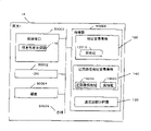
The structure of connection control system of the present invention shown in Fig. 1.In this system, belonging to the terminal 1 (10) of network 1 (1), the terminal 2 (20) that belongs to network 2 (2), the terminal 3 (30) that belongs to network 3 (3), the terminal 4 (40) that belongs to network 4 (4) is connected with gateway 1 (15), gateway 2 (25), gateway 3 (35), gateway 4 (45) by LAN (50010), and is connected in connection control system (5) by these gateways.Essential connection that connection control system (5) possesses the connection control device (52) of communicating by letter between control terminal, carry out authenticate device (54) that the user authenticates, generate circuitous path when connecting is with the address management apparatus (56) of address.Here, refusal communication of 3 (3) from network 1 (1) to network.But, permit from network 1 (1) to network 2 (2) respectively, 3 (3) communication from network 2 (2) to network.
Then, expression constitutes the functional block diagram of each key element of connection control system (5).Fig. 2 is the structure of gateway 1 (15).Connect the connection of control device, also have the same structure with other gateway 2-4 (25,35,45) in connecting Fig. 1 that control device connects for control terminal.
Gateway 1 (15) is by network interface (50000) and PERCOM peripheral communication.Gateway 1 (15) also possesses CPU (50002), hard disk (50004), memory (50008), and they pass through bus (50006) transceiver data each other.In these hardware configurations, gateway 1 (15) possesses reception from the terminal information bag and send to the packets of information transceiver portion (110) of destination-address in network interface (50000), possess the address login form (120) of the terminal real address (12010) that the login permission connects, circuitous path address (13010) and the circuitous path address login form (130) of the group of real address (13020), the communication monitoring timer (140) of monitor communication state that the login circuitous path uses when connecting on memory (50008).
The real address is the address of distributing to the network interface of terminal, connects in permission under the situation of source terminal and linking objective terminal communication, uses this address to communicate.So-called circuitous path connects and is meant and will be connecting under source terminal and the situation that the linking objective terminal can not be communicated by letter, by being used as circuitous path, the connection between the control terminal via the communication path that the network that connects permission is arranged.The circuitous path address is the address that address management apparatus is distributed to terminal under the situation about communicating in circuitous path connects.
Fig. 3 is the structure that connects control device (52).Connect control device (52) as the basic hardware structure, have be used for the outside network interface (50000) that communicates, with CPU (50002), hard disk (50004), bus (50006), memory (50008).And, connect control device (52) and in network interface (50000), possess the packets of information transceiver portion (520) that receives or send the packets of information of self terminal, the message that other device in connection control system (5) send to entrust is handled or with the result of other device information receiving and transmitting letter portion (522) as message sink, in hard disk (50004), possess to comprise and the connection request judgement that comes self terminal is connected the connection permission database (524) of information available perhaps with the address that sends target terminal according to the address that sends source terminal, part as go up the connection control function (52002) of the link control program (52000) that moves at memory (50008) possesses the User Status management department (526) that management connects the User Status of controlling object, the communication monitoring timer (528) of monitor communication state.Here, so-called message is meant the packets of information of exchange between intrasystem each device.
Fig. 4 is the details that connects permission database (524).The internetwork relation that connection permission database (524) keeps permission to connect comprises the circuitous path judgement symbol (5246) that connects source network (5242), linking objective network (5244), represents whether to can be used as circuitous path.At circuitous path judgement symbol (5246) is true time, can be with this communication path as circuitous path.
Fig. 5 is the details of User Status management department (526).Data record of example only among Fig. 5.User Status management department is the functional block that management connects the User Status in the control, comprises user name (5260), terminal address (5261), connects source network (5262), linking objective network (5264), circuitous path judgement symbol (5266), authentication determination sign (5268), circuitous path address (5270), circuitous path address N (5272).Circuitous path judgement symbol (5266) uses under the situation in the circuitous path process to true the object user.Authentication determination sign (5268) when the authentification of user of finishing when connecting source network to linking objective network service for true.
Fig. 6 is the structure of authenticate device (54).Authenticate device (54) is as the basic hardware structure, possesses to be used for and outside network interface (50000), CPU (50002), hard disk (50004), bus (50006), the memory (50008) that communicates.And, authenticate device (54) possesses information receiving and transmitting letter portion (540) in network interface (50000), in hard disk (50004), possesses authentication database (542), part as go up the authentication function (54002) of the authentication procedure (54000) of moving at memory (50008) possesses communication monitoring timer (544).
Fig. 7 is the details of authentication database (542).Data record of example only among Fig. 7.Under the situation of carrying out the circuitous path connection, communicate, but the authentication of this moment is all carried out each communication path via a plurality of communication paths.Authentication database (542) comprises user name (5420), connection source network (5422), linking objective network (5424), the password (5426) of authentication object.
Fig. 8 is the structure of address management apparatus (56).Address management apparatus (56) possesses and outside network interface (50000), CPU (50002), hard disk (50004), bus (50006), the memory (50008) that communicates as the basic hardware structure.And, address management apparatus (56) possesses information receiving and transmitting letter portion (560) in network interface (50000), as the part of the address management function (56002) of the address management (56000) of going up action at memory (50008), possess generate the address generating unit (562) that is used for the address that circuitous path connects, the network information management portion (564), the communication monitoring timer (566) of monitor communication state of essential information when management address generates.
Fig. 9 is the details of network information management portion (564).In connection control system of the present invention, IPv6 is assumed to be communication protocol.Therefore, the identifier (5640) of essential recognition network and the network prefix (5642) in network, used in address that circuitous path is used generates.Under the situation of using IPv4, needn't network prefix (5642) in the address generates.Represent it, the terminal address in the essential supervising the network, and untapped address used the address as circuitous path.Network information management portion (564) shown in Figure 26 among the IPv4.Network information management portion (564) possesses network identifier (5640) and address administration database (5644).
Describe the action of this system below in detail with sequence.Figure 10 represents the basic sequence of connection control system (5).In addition, the content of the packets of information of using in this sequence shown in Figure 19.As mentioned above, connection control system (5) permission is connected to network 2 (2), is connected to network 3 (3) from network 2 (2) and is connected to network 4 (4) from network 3 (3) from network 1 (1).Consider that the whole connections of hypothesis all can be used as circuitous path, and the terminal 1 (10) that belongs to network 1 (1) and the terminal 2 (20) that belongs to network 2 (2) situation about communicating.When beginning to communicate by letter, terminal 1 (10) is connected to the connection request (1000) of network 2 (2) from network 1 (1) by gateway 1 (15) transmission.As long as after not special the description, from terminal to the communication that connects control device (52) via gateway.The content of connection request shown in Figure 19 (1000).Connection request (1000) comprises transmission source IP (2300), destination IP (2302), information bag type (connection request) (2304), connects source network (2306), linking objective network (2308), user name (2310) as information.Connection control device (52) inquiry that receives connection request (1000) connects the whether connection of license request of permission database (524).Connect permission database (524) relatively the linking objective network (2308) that is connected source network (5242), connection request (1000) in connection source network (2306) and the database of connection request (1000) and the linking objective network (5244) in the database, judge whether to permit the connection of being asked.Whether the authentication that then connects control device (52) inquiry this user of User Status management department (526) is finished.In User Status management department (526), do not exist under this user's the situation of catalogue, connect the purpose that control device (52) generates this user, send authentication request (1003) to terminal 1 (10).The content of authentication request shown in Figure 19 (1003).Authentication request (1003) comprises transmission source IP (2700), destination IP (2702), information bag type (authentication request) (2704), connects source network (2706), linking objective network (2708), user name (2710) as information.Under the situation that this User Catalog exists, User Status management department (526) checks the authentication determination sign (5268) of catalogue, under the situation that is puppet, sends authentication request (1003) to terminal 1 (10).After terminal 1 (10) receives request, authentication information (1006) is sent to connection control device (52).The content of authentication information shown in Figure 19 (1006).Authentication information (1006) comprises transmission source IP (2500), destination IP (2502), information bag type (authentication request) (2504), connects source network (2506), linking objective network (2508), user name (2510), password (2512).The connection control device (52) that receives authentication information (1006) sends authentication delegation (1009) to authenticate device (54), entrusts authentication.The content of authentication delegation shown in Figure 19 (1009).Authentication delegation (1009) comprises message kind (authentication delegation) (4300), connects source network (4302), linking objective network (4304), user name (4306), password (4308).From the connection source network (2506) of authentication information (1006), linking objective network (2508), user name (2510), password (2512), obtain the value of connection source network (4302) in the authentication delegation (1009), linking objective network (4304), user name (4306), password (4308).Whether the authenticate device (54) that receives authentication delegation (1009) inquires authentication database (542) authentication success.Authenticate device (54) uses connection source network (4302), linking objective network (4304), the user name (4306) in the authentication delegation (1009), the corresponding data record of retrieval from authentication database (542), and password (4308) in the comparison authentication delegation (1009) and the password (5426) in the data record.Under the situation of password unanimity, notice is finished in authentication connected control device (52).This finishes (1012) by the transmission authentication and carries out.Receiving connection control device (52) that authentication finishes (1012) finishes notice (1015) with authentication and sends to terminal 1 (10).Because finish at this time authentication, so will sending the authentification of user judgement symbol (5268) of the authentication request (1003) of User Status management department (526), connection control device (52) is set at very, circuitous path judgement symbol (5266) is set at vacation.After authentication is finished, connect control device (52) authenticates the user who finishes to gateway (15) address login (1016).The content of the login of address shown in Figure 19 (1016).Address login (1016) comprises transmission source IP (5000), destination IP (5002), information bag type (address login) (5004), real address (5006).Gateway 1 (15) is logined real address (5006) login in the form (120) in the address.
After the User Status in having upgraded User Status management department (526), connect control device (52) and will connect notification of permit (1018) notice terminal 1 (10).The content that connects notification of permit (1018) shown in Figure 19.Connect notification of permit (1018) as information, comprise transmission source IP (3300), destination IP (3302), information bag type (connection notification of permit) (3304), connect source network (3306), linking objective network (3308), user name (3310).Receive the terminal 1 (10) that connects notification of permit (1018) and can communicate with terminal 2 (20), communicate (1021) with terminal 2 via gateway 1 (10), gateway 2 (25) beginnings in this moment.
Terminal 1 (10) finishes (1024) to connecting control device (52) transmission connection when finishing communication.What receive that connection control device (52) deletion that connect to finish (1024) sends User Status management department (526) finishes the user's of (1024) catalogue corresponding to this connections, sends to connect to terminal 1 (10) and finishes affirmation (1027).At last, connection management device (52) sends address deletion (1030) to gateway 1 (15).The content of the deletion of address shown in Figure 19 (1030).Address deletion (1030) comprises transmission source IP (5100), destination IP (5102), information bag type (address deletion) (5104), real address (5106).Gateway 1 (15) is deletion real address (5106) from address login form (120).After, via connection control device (52) and during terminal 2 (20) is communicated by letter, must send connection request (1000) and process authentication in terminal 1 (10) once more.More than, common connection processing is finished.
Below, consider not connect the communication between the network of permitting.Figure 12 is that request is from the processing of network 1 (1) under the situation of network 3 (3) communications.The terminal 2 (20) that is equivalent to belong among Fig. 1 network 2 (2) moves to network 1 (1) (9), becomes terminal 1 (10), situation about communicating with the terminal 3 (30) that belongs to network 3 (3).
In system of the present invention,, solved the problem that can not connect between the network of connection permission by using the communication of circuitous path.Circuitous path is a communication path of realizing not connecting the communication between the network of permission.Among Fig. 1,, exist from network 1 (1) to network 2 (2), from the connection permission of network 2 (2) to network 3 (3) though do not exist from the connection permission of network 1 (1) to network 3 (3).Therefore, by realizing from the communication of network 1 (1) to network 3 (3) via the circuitous path of network 2 (2).At this moment, terminal must have the address of satisfying the connection permission.From network 1 (1) communicates via network 2 (2) and the terminal 3 (30) that belongs to network 3 (3), must still, connect permission in order to satisfy in terminal 1 from network 2 (2) to network 3 (3) communications, terminal 1 (10) must have the address in the network 2 (2)., because the address that terminal 1 (19) has belongs to network 1 (1), so can not former state communicate by letter to network 3 (3) from network 2 (2).Therefore, address management apparatus (56) is given terminal 1 (10) with the address in the network 2 (2) as the circuitous path address.By the communication in the network 2 (2) is distributed to terminal with the address, can carry out via network 2 (2), promptly use the communication of circuitous path.
Use the communication sequence of circuitous path shown in Figure 11.In addition, the content of the packets of information of using in this sequence shown in Figure 20, Figure 21.Terminal 1 (10) sends connection request (1200) to connecting control device (52).Connection control device (52) inquiry that receives connection request (1200) connects the whether connection of license request of permission database (524).Because refusal communicates to network 3 (3) from network 1 (1), send refusal connection notice (1203) to terminal 1 (10) so connect control device (52).Refusal connects the content of notice (1203) shown in Figure 20.Refusal connects notice (1203) and comprises information transmission source IP (3500), destination IP (3502), information bag type (connection notification of permit) (3504), connects source network (3506), linking objective network (3508), user name (3510) as information.Receive refusal and connect the terminal (10) of notice (1203) owing to know and can not directly connect to network 3 (3) from network 1 (1), request connects the connection of control device (52) based on circuitous path, so send circuitous path connection request (1206).The content of the connection request of circuitous path shown in Figure 20.Circuitous path connection request (1206) comprises transmission source IP (2400), destination IP (2402), information bag type (circuitous path connection request) (2404), connects source network (2406), linking objective network (2408), user name (2410) as information.In this example, to connecting source network (2406) specified network 1 (1), to linking objective network specified network 3 (3).Connection control device (52) inquiry that receives circuitous path connection request (1206) connects the circuitous path whether permission database (524) exists request.Connecting permission database (524) uses the connection source network (2406) of circuitous path connection request (1200) and linking objective network (2408) to retrieve circuitous path.Connect permission database (524) under situation about can construct by the network connections of connection permission, be judged as and make a circulation with self-management from the path that connects source network binding linking objective network.So-called network connections is meant that having the linking objective network that connects permission 1 connects under the consistent situation of the connection source network of permission 2 with other, and the connection source network that generation will connect permission 1 becomes and connects source network, will connect the new connection of permitting 2 linking objective network to become the linking objective network and permit 3.For example, with regard to from network 1 (1) to network with regard to 3 (3), have from network 1 (1) to network 2 (2) in the connection permission in connecting permission database, from network 2 (2) to network paths such as 3 (3), possible binding Network Based is made a circulation.If be judged as possibility, then connect control device (52) inquiry User Status management department (526) and whether finish the authentification of user that sends circuitous path connection request (1206).At this moment, owing to also do not generate this user's catalogue in the User Status management department (526),, circuitous path authentication request (1209) is sent to terminal 1 (10) so connect the catalogue that control device (52) generates this user.The content of the authentication request of circuitous path shown in Figure 20 (1209).Circuitous path authentication request (1209) comprises transmission source IP (2800), destination IP (2802), information bag type (circuitous path authentication request) (2804), connects source network (2806), junction network 1 (2808), junction network N (2810), linking objective network (2812), user name (2814) as information.N represents N junction network.In this example, because via network 2 (2), so to connecting source network (2806) specified network 1 (1), to junction network 1 (2808) specified network 2 (2), to linking objective network (2812) specified network 3 (3).In specifying, uses on network each network identifiable information.Network identifier (5640) that the network information management portion (564) of the address of gateway of each network or address management apparatus (56) of for example belonging to has etc. is equivalent to this.The terminal 1 (10) that receives circuitous path authentication request (1209) sends to circuitous path authentication information (1212) and connects control device (52).Circuitous path authentication information (1212) must comprise via the essential authentication information of whole circuitous paths.
The content of the authentication information of circuitous path shown in Figure 20 (1212).Circuitous path authentication information (1212) comprises transmission source IP (2600), destination IP (2602), information bag type (circuitous path authentication information) (2604), connects source network (2606), junction network 1 (2608), junction network N (2610), linking objective network (2612), user name (2614), password 1 (2616), password N+1 (2618).Password I represents password essential when junction network I-1 is connected to junction network I.Junction network 0 is corresponding to connecting source network (2608), and junction network N+1 is corresponding to linking objective network (2610).The connection control device (52) that receives circuitous path authentication information (1212) sends circuitous path authentication delegation (1215) to authenticate device (54), entrusts authentication.The content of the authentication delegation of circuitous path shown in Figure 20 (1215).Circuitous path authentication delegation (1215) comprises message kind (circuitous path authentication delegation) (4400), connects source network (4402), junction network 1 (4404), junction network N (4406), linking objective network (4408), user name (4410), password 1 (4412), password N+1 (4414).Junction network is the same with circuitous path authentication information (1212) with the footnote relation of password.Whether the authenticate device (54) that receives circuitous path authentication delegation (1215) inquires authentication database (542) authentication success.Authenticate device (54) is to the whole passwords in the circuitous path authentication delegation (1215), be connected source network (5422), linking objective network (5424), user name (5420), password (5426) with junction network I-1, junction network I, user name (4410), password I and authentication database (542) compares respectively, whole passwords are existed under the situation of data record, notice is finished in authentication connected control device (52).This finishes (1218) by the authentication of transmission circuitous path and carries out.The content of (1218) is finished in the authentication of circuitous path shown in Figure 20.The circuitous path authentication is finished (1218) as information, comprises message kind (the circuitous path authentication is finished) (3900), connects source network (3902), junction network 1 (3904), junction network N (3906), linking objective network (3908), user name (3910).Receiving circuitous path authentication finishes the connection control device (52) of (1218) and notice (1221) is finished in the circuitous path authentication is sent to terminal 1 (10).
The content of notice (1221) is finished in the authentication of circuitous path shown in Figure 21.The circuitous path authentication is finished notice (1221) and is comprised transmission source IP (3000), destination IP (3002), information bag type (notice is finished in the circuitous path authentication) (3004), connects source network (3006), junction network 1 (3008), junction network N (3010), linking objective network (3012), user name (3014) as information.Because this moment authentication is finished, this user's of User Status management department (526) authentication determination sign (5268) is set at very with circuitous judgement symbol (5266) so connect control device (52).As mentioned above, when connecting, circuitous path must generate the circuitous path address of terminal to each junction network.Connecting control device (52) entrusts address management apparatus (56) to generate the circuitous path address.This processing entrusts (1244) to carry out by send the address generation to address management apparatus (56).Address shown in Figure 21 generates the content of entrusting (1244).The address generates entrusts (1244) to comprise message kind (address generates and entrusts) (4500), terminal MAC Address (4502), junction network 1 (4504), junction network N (4506) as information.The MAC Address of terminal can extract from the terminal address (5261) of User Status management department (526), sends to address management apparatus (56) when entrusting the address to generate.Receiving the address generation entrusts the address management apparatus (56) of (1224) to carry out address generation processing.The generation of address generates the terminal MAC Address (4502) of entrusting in (1224) and carries out with detected network prefix (5642) from the gateway address of junction network I by the address that receives.Under the situation of IPv4, search address management database (5644) is used as calculated address with untapped address.Address management apparatus (56) uses the address to generate and finishes (1227), the address notification that generates is given connect control device (52).
Address shown in Figure 21 generates finishes the content of (1227).The address generation is finished (1227) and is comprised message kind (address generates and finishes) (4200), terminal MAC Address (4202), calculated address 1 (4204), calculated address N (4206) as information.Calculated address I is that the address generates the pairing address of junction network I of entrusting (1224).Receive the address generate finish (1227) connection control device (52) with the address login in the circuitous path address of User Status management department (526).Here, the circuitous path address of network 2 (2) usefulness is logined for circuitous path address (5270) entirely.Then, the address is generated notice (1230) send to terminal 1 (10), the address that notice generates.Address shown in Figure 21 generates the content of notice (1230).The address generates notice (1230) and comprises transmission source IP (3700), destination IP (3702), information bag type (address generates notice) (3704), terminal address (3706), calculated address 1 (3708), calculated address N (3710) as information.Terminal 1 (10) receives the address of network 2 (2) usefulness, is used for later communication.This is handled as described later.End connects in order to carry out circuitous path to the connection control device (52) of terminal 1 (10) Notify Address, carries out the address login to the gateway that is present on the communication road.In being present in the gateway of communication on the road, gateway 1 (15), gateway 2 (25), gateway 3 (35) are arranged, but respectively gateway 1 (15) is carried out in order to connect permission necessary address login, to carry out for the circuitous path necessary address login of communicating by letter to gateway 2 (25) here.Connect control device (52) and send address login (1231) to gateway 1 (15).Here Deng Lu address is the address of terminal 1 (10), and it is stored in the terminal address (5261) of User Status management department (526).Then, connect control device (52) and send circuitous path address login (1232) to gateway 2 (25).The content of the address of circuitous path shown in Figure 21 login (1232).Circuitous path address login (1232) comprises transmission source IP (5200), destination IP (5202), information bag type (login of circuitous path address) (5204), circuitous path address (5206), real address (5208) as information.Circuitous path address (5206) is that the terminal that is present on the linking objective network sends the necessary address of follow-up bag to the circuitous path network, in this example, is equivalent to the address that network 2 (2) is generated.Real address (5208) is that the gateway that is present on the junction network transmits the necessary address of follow-up bag, is equivalent to the address that a junction network is before generated.That is, under the situation of junction network I, the address that network I is generated is equivalent to the circuitous path address, and the address that network I-1 is generated is equivalent to the real address.In addition, network 1 is the network under the terminal.Here, the address with network 2 (2) usefulness is assigned to circuitous path address (5206).It is stored in the circuitous path address 1 (5270) of User Status management department (526).The address of terminal 1 (10) is assigned to real address (5208).It is stored in the terminal address (5261) of User Status management department (526).The connection control device (52) that finishes login that must the address connects notification of permit (1233) with circuitous path and sends to terminal 1 (10).Circuitous path shown in Figure 21 connects the content of notification of permit (1233).Circuitous path connects notification of permit (1233) and comprises transmission source IP (3400), destination IP (3402), information bag type (circuitous path connection notification of permit) (3404), connects source network (3406), junction network 1 (3408), junction network N (3410), linking objective network (3412), user name (3414) as information.The terminal that receives circuitous path connection notification of permit (1233) communicates (1236) via gateway 1 (15), gateway 2 (25), gateway 3 (35) with terminal 3 (30).
Terminal 1 (10) finishes (1239) to connecting control device (52) transmission connection when finishing communication.Receive the catalogue that connects connection control device (52) the deletion User Status management department (526) that finishes (1239), send to connect to terminal 1 (10) and finish to confirm (1242) corresponding to the user who sends this connection end (1239).At last, connection management device (52) sends address deletion (1245) in order to delete the address of login in gateway to gateway 1 (15).The content of address deletion (1245) is the same with the content that (1030) are deleted in address shown in Figure 19.Gateway 1 (15) is deletion real address (5106) from address login form (120), after, the communication of terminal 1 (10) in order to carry out via connection control device (52) and terminal 3 (30) being connected based on circuitous path must send circuitous path connection request (1206) and process authentication once more.Then, connect control device (52) and send circuitous path address deletion (1248) to gateway 2 (25).The content of the address of circuitous path shown in Figure 21 deletion (1248).Circuitous path address deletion (1248) comprises transmission source IP (5300), destination IP (5302), information bag type (deletion of circuitous path address) (5304), circuitous path address (5306), real address (5308) as information.Above circuitous path connection processing is finished.
Describe the action of each functional block below in detail with flow chart.
Figure 12 is the flow chart that connects control device (52).Connect control device (52) and when system start-up, begin to handle (1300), enter the messages/information bag and receive loop (1301).Be (1302) under the situation of connection request (1000) in the message that receives, connect control device (52) and carry out connection processing (1324).Connection processing (1324) as described later.Be (1304) under the situation of circuitous path connection request (106) in the message that receives, connect control device (52) and carry out circuitous path connection processing (1326).Circuitous path connection processing (1326) as described later.Under the situation that receives authentication information (1006) (1306), connect control device (52) and entrust authenticate device (54) to authenticate (1328).Under the situation that receives circuitous path authentication information (1212), connect control device (52) and entrust authenticate device (54) to carry out circuitous path authentication (1330).Receiving (1310) under the situation of authentification failure, connecting control device (52) notice terminal authentication failure (1332).Authentification failure is the message that notice connects control device (52) authenticate device (54) authentification failure.Under the situation that receives the circuitous path authentification failure (1312), connect control device (52) notice terminal circuitous path authentification failure (1334).The circuitous path authentification failure is that notice connects the message of control device (52) about authenticate device (54) circuitous path authentification failure.The content of the authentification failure of circuitous path shown in Figure 22.The circuitous path authentification failure comprises message kind (circuitous path authentification failure) (4100), connects source network (4102), junction network 1 (4104), junction network N (4106), linking objective network (4108), user name (4110) as information.Connect control device and send the circuitous path authentication failure notification to terminal.The content of the authentication failure notification of circuitous path shown in Figure 22.The circuitous path authentication failure notification comprises transmission source IP (3200), destination IP (3202), information bag type (circuitous path authentication failure notification) (3204), connects source network (3206), junction network 1 (3208), junction network N (3210), linking objective network (3212), user name (3214) as information.Finish under the situation of (1012) (1314) receiving authentication, connect control device (52) and finish notice (1015) to terminal transmission authentication, notification authentication is finished (1336), send address login (1030) to gateway, the address login of terminal is logined in the form (120) (1338) in the address, to connect notification of permit (1018) and send to terminal, make communication beginning (1340).Finish under the situation of (1218) (1316) receiving circuitous path authentication, connect control device (52) and finish notice (1221) to the authentication of terminal transmission circuitous path, (1342) are finished in the authentication of notice circuitous path, send the address to address management apparatus and generate trust (1224), entrust calculated address (1344).Generate under the situation finish (1227) (1318) receiving the address, connect control device (52) address is generated notice (1230) to terminal transmission (1346), by address login (1231), circuitous path address login (1232), the address of terminal and the circuitous path address of generation are logined in gateway (1348), circuitous path is connected notification of permit (1233) send to terminal (1350).Receiving from terminal under the situation that connects end (1239) (1320), connect control device (52) and will connect end affirmation (1242) to terminal transmission (1352), by address deletion (1245), circuitous path address deletion (1248), from gateway, delete corresponding address (1354).Packets of information/message sink loop stops (1322) when stopping in system, connect control device (52) and finish (1399).
Below, Figure 13 illustrates the state of connection processing.When connection processing begins (1400), at first, retrieve (1402) to connecting permission database (524) in order to hold the whether connection of license request.Be not present in the connection permission database (524) as if corresponding data record, then connect control device (52) and will refuse to connect notice (1203), finish connection processing (1499) to terminal transmission (1420).Exist under the situation of data record, retrieval user condition managing portion (526) checks whether authentication finishes (1404).Under the uncompleted situation of authentication, authentication request (1003) is sent (1422) to terminal, finish connection processing (1499).Under the situation that authentication is finished, send (1406) to connecting notification of permit (1018), finish connection processing (1499).
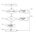
Below, the state of the connection processing of circuitous path shown in Figure 14.When beginning circuitous path connection processing (1500), in order to hold the circuitous path that whether has request, retrieve (1502) at first to connecting permission database (524).Can not from connect permission database (524), calculate under the situation of circuitous path, connect control device (52) and send refusal circuitous path connection notice (1520), finish connection processing (1599) to terminal.Figure 22 illustrates the content that the refusal circuitous path connects notice.The refusal circuitous path connects notice and comprises transmission source IP (3600), destination IP (3602), information bag type (circuitous path connection notification of permit) (3604), connects source network (3606), linking objective network (3608), user name (3610) as information.Exist under the situation of circuitous path, retrieval user condition managing portion (526) checks whether authentication finishes (1504).Under the uncompleted situation of authentication, circuitous path authentication request (1209) is sent (1522) to terminal, finish connection processing (1599).Under the situation that authentication is finished, whether inquiry User Status management department (526) address has generated.Whether the address generates judges at circuitous path judgement symbol (5266) to be under the genuine situation, by existing circuitous path address (5270) to carry out.Under the situation about not generating in the address, connect control device (52) and the address is generated entrust (1224) to send (1524) to address management apparatus (56).Under the situation about having generated in the address, send the address to terminal and generate notice (1230), carry out address notification (1508), circuitous path is connected notification of permit (1233) send (1510), finish circuitous path connection processing (1599).
Figure 15 is the flow chart of authenticate device (54).Authenticate device (54) begins to handle (1600) when system start-up, enters message sink loop (1601).Be (1602) under the situation of authentication delegation (1009) in the message that receives, authenticate device (54) carries out authentication processing (1620).Authentication processing as described later.Be (1604) under the situation of circuitous path authentication delegation (1215) in the message that receives, authenticate device (54) carries out circuitous path authentication processing (1622).The message sink loop stops (1606) when stopping in system, authenticate device finishes (1699).
Below, the state of authentication processing shown in Figure 16.When the beginning authentication processing (1700), whether the user name in the initial retrieving authentication information is present in the authentication database (542) (1702).Under the non-existent situation of user name, authenticate device (54) sends authentification failure (1720), end process (1799) to connecting control device (52).Under the situation that user name exists, correctly whether retrieve password (1704).Under the incorrect situation of password, authenticate device (54) sends authentification failure (1722), end process (1799) to connecting control device (52).Under the correct situation of password, authenticate device (54) is finished authentication (1012) and is sent (1706), end process (1799) to connecting control device (52).
Below, the state of the authentication processing of circuitous path shown in Figure 17.When beginning circuitous path authentication processing (1800), whether the user name in the initial retrieving authentication information is present in the authentication database (542) (1802).Under the situation that does not have user name, authenticate device (54) sends circuitous path authentification failure (1820), end process (1899) to connecting control device (52).Under the situation that user name exists, correctly whether retrieve password (1804).Only in circuitous path authentication under all correct situation of essential whole passwords, it is correct just to be considered as password.Under the incorrect situation of password, authenticate device (54) sends circuitous path authentification failure (1822), end process (1899) to connecting control device (52).Under the correct situation of password, authenticate device (54) is finished (1218) with the circuitous path authentication and is sent (1806), end process (1899) to connecting control device (52).
Figure 18 is the flow chart of address management apparatus (56).Address management apparatus (56) begins to handle (1900) when system start-up, enters message sink loop (1901).When address management devices receiver address generates trust (1224) (1902), connect with address (1904) from relaying network N (4506) generation circuitous path, the address is generated finish (1227) to connection control device (52) transmission (1906).The message sink loop stops (1908) when stopping in system, address management apparatus finishes (1999).
Below, the packets of information processing of terminal 1 (10) when terminal 3 (30) communicates is described.Figure 27 is the sequential of terminal 1 (10) when terminal 3 (30) communications.Among Figure 11, generate the moment of notice (1230) at terminal 1 (10) receiver address, the address that terminal 1 (10) keeps as network 2 (2) usefulness of circuitous path network 1, it is Host1 that terminal 1 (10) the initial address that keeps is recorded and narrated, it is Host1-2 that the circuitous address of network 2 (2) usefulness is recorded and narrated.When gateway (15) receiver address login (1231), in the address login form (120) of gateway 1 (15), terminal 1 (10) can communicate through gateway (15) with the Host1 login.When gateway 2 (25) receives circuitous path addresses logins (1232), with Host1-2 as circuitous path address (13010), with Host1 as real address (13020) login in the circuitous path address login form (130) of gateway 2 (25).These information are essential from terminal 3 when terminal 1 sends packets of information in circuitous path connects.When terminal 1 (10) received circuitous path connection notification of permit (1233), terminal 1 (10) knew that communication sends via gateway 1,2,3.Terminal 1 (10) sends packets of information to terminal 3 (30) according to the following steps.Terminal 1 (10) sends (5499) with packets of information (5498) to gateway 1 (15) at first.The packets of information (5498) that terminal 1 (10) sends to gateway 1 (15) comprises the starting point (5400) of the genuine starting point (5408) of packets of information, genuine terminal point (5410), channel communication, the terminal point (5402) of channel communication, circuitous head (header) 1 (5404), circuitous head 2 (5406) and Payload (5412).Because 3 (30) communication is at first via gateway 1 (15) from terminal 1 (10) to terminal, so the starting point that Host1 (5450) is assigned to channel communication is assigned to terminal point with GW1 (5452).GW1 is the address of gateway 1 (15), is contained in circuitous path and connects in the connection source network (3406) of notification of permit (1233).Connect permission in order to satisfy, packets of information must be via gateway 2 (25), gateway 3 (35).In order to realize this step, terminal 1 (10) is inserted two circuitous heads in the packets of information.Circuitous head is specified the transmission source in pairs and is sent purpose.Here, specify respectively from gateway 1 (15) to gateway 2 (25) circuitous head (5454), from gateway 2 (25) to gateway 3 (35) circuitous head (5456).Be assigned to the genuine terminal point of packets of information to Host3, but the problem here is in genuine starting point as the address of terminal 3 (30).When terminal 3 receives packets of information, during the return information bag, might only return to the network that the connection permission is arranged from network 3 (3).Therefore, the circuitous address Host1-2 with network 2 usefulness is appointed as genuine starting point.Because calculate circuitous address so that the permission of connection must be arranged for terminal point, thus be assigned to genuine starting point by the address that will make a circulation, can be from terminal 3 (30) return information bags.Comprise the data (5462) that send to terminal 3 (30) in the Payload (5412).The gateway 1 (15) that receives packets of information (5498) from terminal 1 is the process information bag according to the following steps.According to the starting point (5400) and terminal point (5402) of channel communication, the terminal point of holding channel communication is own own, removes these points.Then, gateway 1 (15) retrieval of head of making a circulation.Terminal 1 (10) sends to the middle circuitous head 1 (5404) that exists request to travel back across gateway 2 (25) from gateway 1 (15) of packets of information (5498) of gateway 1 (15), so the starting point of channel communication is assigned to GW1 (5550), terminal point is assigned to GW2 (5552), remove a circuitous head, only specify from gateway 2 to gateway 3 circuitous head (5554).The data (5556,5558,5560) of the packets of information that genuine starting point (5506), genuine terminal point (5508), Payload (5510) slavish copying are original.Through above processing, gateway 1 (15) sends (5599) with packets of information (5598) to gateway 2 (25).The gateway 2 (25) that receives this packets of information carries out the processing the same with gateway 1 (15), and packets of information (5698) is sent (5699) to gateway 3 (35).The starting point of channel communication is GW2 (5650), and terminal point is GW3 (5652), and genuine starting point is Host1-2 (5654), and genuine terminal point is Host3 (5656).Payload (5658) does not change.Receive gateway 3 (35) the analytical information bags of this packets of information, there is not circuitous head in understanding.Therefore, the packets of information channelizing that gateway 3 (35) will not receive from gateway 2 (25), and handle as common communication.Because the genuine terminal point of packets of information is Host3, so gateway 3 (35) is constructed packets of information shown in Figure 26.The starting point of packets of information is Host1-2 (5750), and terminal point is Host3 (5752).Payload (5754) does not change.The packets of information of so constructing (5798) incoming terminal 3 (30) (5799).
The following describes packets of information and turn back to terminal 1 (10) from terminal 3 (30).The improvement source of the packets of information that terminal 3 is held is the Host 1-2 (5750) by starting point (5700) appointment of the packets of information (5798) that receives from gateway 3 (35).According to this information, terminal 3930) constructs the packets of information (5898) of terminal 1 (10).Terminal 3 (30) is set the genuine starting point of packets of information for Host3 (5854), sets genuine terminal point for Host1-2 (5856), sets the starting point of channel for Host3 (5850), sets the terminal point of channel for GW3 (5852).Receive the gateway 3 (35) of this packets of information because the genuine terminal point of (5899) packets of information is Host1-2, so construct packets of information (5998) packets of information that sends to gateway 1 (15) (5999).Genuine starting point (5904), genuine terminal point (5906), Payload (5908) do not change.Set the starting point of channel for GW3 (5950), set the terminal point of channel for GW2 (5952).Receive the transmission purpose of gateway 2 (25) retrieving information bag in network 2 (2) of this packets of information, but because Host1-2 is the virtual address that terminal 1 (10) is used in network 2 (2), so the transmission purpose of packets of information does not exist.Therefore, gateway 2 (25) retrieval circuitous path address login forms (130) check whether corresponding circuitous path does not exist.With Host1-2 as circuitous path address (13010), with Host1 as real address (13020) login in the circuitous path address of gateway 2 (25) login form (130), so gateway 2 (25) sends to gateway 1 (15) with packets of information.According to above information, gateway 2 (25) sends to gateway 1 (15) with packets of information (6098).The starting point of channel (6050) is configured to GW2, and the terminal point of channel is configured to GW1 (6052).Genuine starting point is Host3 constant (6054), but genuine terminal point is varied to the Host1 (6056) as the real address of extracting (13020) from circuitous path address login form (130).Reception knows that from the gateway 1 (15) of the packets of information (6098) of gateway 2 (25) terminal point of packets of information is Host1, constructs packets of information (6198), sends to terminal 1 (10) (6199).The starting point of this packets of information is configured to Host3 (6150), and terminal point is configured to Host1 (6152).Through above processing, packets of information is returned terminal 1 (10) from terminal 3 (30).
Below, shown in Figure 23 connection control system is embodied as the structure under the situation of a connection management device (6).Connection management device (6) bottom line possesses network interface (50000) and bus (50006), memory (50008).The structure of connection management device (6) is described in detail in Figure 25.Connection management device (6) possesses connection control function (60002), authentication (60004), address management function (60006), as the function that goes up the connection management program (60000) of action at memory (50008).Each function provides and is connected control device (52), authenticate device (54), the equal function of address management apparatus (56), and it is the same with Figure 10, Figure 11 to handle sequence.
Below, represent the hardware configuration of system with Figure 24.As shown in Figure 1, connection control system (5) is by connecting control device (52), authenticate device (54) and address management apparatus (56) formation.These devices possess network interface (50000) respectively, communicate each other by LAN (50010).Each device possesses CPU (50002), hard disk (50004), memory (50008) in addition, and they come transceiver data each other by the bus (50006) in the device.Storage realizes the program of each apparatus function in the memory (50008) of each device.Link control program (52000) is gone up action at the memory (50008) that connects control device (52), and this program possesses connection control function (52002).Equally, the authentication procedure (54000) that possesses authentication function (54002) goes up action at the memory (50008) of authenticate device (54), and the address management (56000) that possesses address management function (56002) is gone up action at the memory (50008) of address management apparatus (56).As the realization form of these devices,, also can resemble leaf (blade) server to become the form of single framework to realize a plurality of Computer Processing except that distributing the independent computer to each device.In addition, also repertoire can be installed in the single computer.The installation of the connection management device (6) shown in Figure 25 under the single hardware.Connection management device (6) is the same with each device of Figure 24, possesses network interface (50000), communicates with one another with exterior terminal, gateway by LAN (50010).Connection management device (6) also possesses CPU (50002), hard disk (50004), memory (50008), and they come transceiver data each other by the bus (50006) in the device.The connection management program (60000) that possesses the function of connection management device (6) goes up action at memory (50008).Connection management program (60000) possesses connection control function (60002), authentication function (60004), address management function (60006), these functional blocks have and are connected control device (52), authenticate device (54), address management apparatus (56) identical functions, and processing procedure is the same with Figure 10, Figure 11.
Lift several examples of application below.Figure 28 is to use vpn server (70) to come the example of construction systems.General vpn server (70) is following server, promptly in communication as send source network with send objective network is connected permission to managing, only permit, manage and have that connection is permitted and the communication of the terminal that authentification of user is finished by oneself.It can be considered as having simultaneously the device of connection control device (52) and the function of authenticate device (54).
Figure 28 illustrates vpn server (70) is applicable to state in the connection control system (5).By the interlock of vpn server (70) and address management apparatus (56), can carry out Figure 10, connection control shown in Figure 11.
Figure 29 is the installation example that connection control system (5) and TV conference system (7) are linked.TV conference system (7) by IV Conference server (72), carry out constituting based on scene (presence) server (74) of the sip server that calls control (76) that carries out standardized SIP (SessionInitiation Protocol) by IETF, management TV convention goer's state.TV Conference server (72) is inquired presence server (74) participant's state when meeting begins, obtain the participant whether in current terminal or belong to present information such as which network.At this moment and since terminal under network, may not can from Conference server (72) to terminal communication.In this case, can consider that Conference server (72) or sip server (76) use connection control system to guarantee communication attainability to terminal.Also can be used as individual system TV conference system (7) and connection control system (5) are installed, at this moment, for example can consider pack into the mounting means of the function that connects control device (52) of sip server (76).
Above-mentioned connection management function is realized by following program.
A kind of program can be carried out in server, and this server is connected with first and second terminal through communication network, possesses:
The transceiver portion that is connected with above-mentioned communication network; With the CPU that is connected with above-mentioned transceiver portion, wherein, this program is carried out above-mentioned server to connect control method, and this connection control method has following steps:
Transceiver portion receives the connection request from above-mentioned first terminal to above-mentioned second terminal;
Can above-mentioned CPU judges be connected to above-mentioned second terminal from above-mentioned first terminal;
Above-mentioned judged result is under the impossible situation of above-mentioned connection, and above-mentioned CPU generates the address that can be connected with above-mentioned second terminal; With
The data that above-mentioned transceiver portion will comprise this address send to above-mentioned first terminal.