CN100448499C - Cone-beam computerized tomography with flat-panel image - Google Patents
Cone-beam computerized tomography with flat-panel image Download PDFInfo
- Publication number
- CN100448499C CN100448499C CNB018082793A CN01808279A CN100448499C CN 100448499 C CN100448499 C CN 100448499C CN B018082793 A CNB018082793 A CN B018082793A CN 01808279 A CN01808279 A CN 01808279A CN 100448499 C CN100448499 C CN 100448499C
- Authority
- CN
- China
- Prior art keywords
- radiotherapy system
- cone
- objective body
- ray
- image
- Prior art date
- Legal status (The legal status is an assumption and is not a legal conclusion. Google has not performed a legal analysis and makes no representation as to the accuracy of the status listed.)
- Expired - Lifetime
Links
Images


Classifications
-
- A—HUMAN NECESSITIES
- A61—MEDICAL OR VETERINARY SCIENCE; HYGIENE
- A61B—DIAGNOSIS; SURGERY; IDENTIFICATION
- A61B6/00—Apparatus for radiation diagnosis, e.g. combined with radiation therapy equipment
- A61B6/02—Devices for diagnosis sequentially in different planes; Stereoscopic radiation diagnosis
- A61B6/03—Computerised tomographs
- A61B6/032—Transmission computed tomography [CT]
-
- A—HUMAN NECESSITIES
- A61—MEDICAL OR VETERINARY SCIENCE; HYGIENE
- A61B—DIAGNOSIS; SURGERY; IDENTIFICATION
- A61B6/00—Apparatus for radiation diagnosis, e.g. combined with radiation therapy equipment
- A61B6/40—Apparatus for radiation diagnosis, e.g. combined with radiation therapy equipment with arrangements for generating radiation specially adapted for radiation diagnosis
- A61B6/4064—Apparatus for radiation diagnosis, e.g. combined with radiation therapy equipment with arrangements for generating radiation specially adapted for radiation diagnosis specially adapted for producing a particular type of beam
- A61B6/4085—Cone-beams
-
- A—HUMAN NECESSITIES
- A61—MEDICAL OR VETERINARY SCIENCE; HYGIENE
- A61B—DIAGNOSIS; SURGERY; IDENTIFICATION
- A61B6/00—Apparatus for radiation diagnosis, e.g. combined with radiation therapy equipment
- A61B6/46—Apparatus for radiation diagnosis, e.g. combined with radiation therapy equipment with special arrangements for interfacing with the operator or the patient
- A61B6/461—Displaying means of special interest
- A61B6/466—Displaying means of special interest adapted to display 3D data
-
- A—HUMAN NECESSITIES
- A61—MEDICAL OR VETERINARY SCIENCE; HYGIENE
- A61B—DIAGNOSIS; SURGERY; IDENTIFICATION
- A61B6/00—Apparatus for radiation diagnosis, e.g. combined with radiation therapy equipment
- A61B6/50—Clinical applications
- A61B6/508—Clinical applications for non-human patients
-
- A—HUMAN NECESSITIES
- A61—MEDICAL OR VETERINARY SCIENCE; HYGIENE
- A61B—DIAGNOSIS; SURGERY; IDENTIFICATION
- A61B6/00—Apparatus for radiation diagnosis, e.g. combined with radiation therapy equipment
- A61B6/58—Testing, adjusting or calibrating apparatus or devices for radiation diagnosis
- A61B6/582—Calibration
- A61B6/583—Calibration using calibration phantoms
-
- A—HUMAN NECESSITIES
- A61—MEDICAL OR VETERINARY SCIENCE; HYGIENE
- A61N—ELECTROTHERAPY; MAGNETOTHERAPY; RADIATION THERAPY; ULTRASOUND THERAPY
- A61N5/00—Radiation therapy
- A61N5/10—X-ray therapy; Gamma-ray therapy; Particle-irradiation therapy
- A61N5/1048—Monitoring, verifying, controlling systems and methods
- A61N5/1049—Monitoring, verifying, controlling systems and methods for verifying the position of the patient with respect to the radiation beam
-
- A—HUMAN NECESSITIES
- A61—MEDICAL OR VETERINARY SCIENCE; HYGIENE
- A61B—DIAGNOSIS; SURGERY; IDENTIFICATION
- A61B6/00—Apparatus for radiation diagnosis, e.g. combined with radiation therapy equipment
- A61B6/02—Devices for diagnosis sequentially in different planes; Stereoscopic radiation diagnosis
- A61B6/027—Devices for diagnosis sequentially in different planes; Stereoscopic radiation diagnosis characterised by the use of a particular data acquisition trajectory, e.g. helical or spiral
-
- A—HUMAN NECESSITIES
- A61—MEDICAL OR VETERINARY SCIENCE; HYGIENE
- A61B—DIAGNOSIS; SURGERY; IDENTIFICATION
- A61B6/00—Apparatus for radiation diagnosis, e.g. combined with radiation therapy equipment
- A61B6/06—Diaphragms
-
- A—HUMAN NECESSITIES
- A61—MEDICAL OR VETERINARY SCIENCE; HYGIENE
- A61B—DIAGNOSIS; SURGERY; IDENTIFICATION
- A61B6/00—Apparatus for radiation diagnosis, e.g. combined with radiation therapy equipment
- A61B6/44—Constructional features of apparatus for radiation diagnosis
- A61B6/4405—Constructional features of apparatus for radiation diagnosis the apparatus being movable or portable, e.g. handheld or mounted on a trolley
-
- A—HUMAN NECESSITIES
- A61—MEDICAL OR VETERINARY SCIENCE; HYGIENE
- A61B—DIAGNOSIS; SURGERY; IDENTIFICATION
- A61B6/00—Apparatus for radiation diagnosis, e.g. combined with radiation therapy equipment
- A61B6/44—Constructional features of apparatus for radiation diagnosis
- A61B6/4429—Constructional features of apparatus for radiation diagnosis related to the mounting of source units and detector units
- A61B6/4458—Constructional features of apparatus for radiation diagnosis related to the mounting of source units and detector units the source unit or the detector unit being attached to robotic arms
-
- A—HUMAN NECESSITIES
- A61—MEDICAL OR VETERINARY SCIENCE; HYGIENE
- A61B—DIAGNOSIS; SURGERY; IDENTIFICATION
- A61B6/00—Apparatus for radiation diagnosis, e.g. combined with radiation therapy equipment
- A61B6/48—Diagnostic techniques
- A61B6/482—Diagnostic techniques involving multiple energy imaging
-
- A—HUMAN NECESSITIES
- A61—MEDICAL OR VETERINARY SCIENCE; HYGIENE
- A61N—ELECTROTHERAPY; MAGNETOTHERAPY; RADIATION THERAPY; ULTRASOUND THERAPY
- A61N5/00—Radiation therapy
- A61N5/10—X-ray therapy; Gamma-ray therapy; Particle-irradiation therapy
- A61N5/1048—Monitoring, verifying, controlling systems and methods
- A61N5/1049—Monitoring, verifying, controlling systems and methods for verifying the position of the patient with respect to the radiation beam
- A61N2005/1061—Monitoring, verifying, controlling systems and methods for verifying the position of the patient with respect to the radiation beam using an x-ray imaging system having a separate imaging source
-
- A—HUMAN NECESSITIES
- A61—MEDICAL OR VETERINARY SCIENCE; HYGIENE
- A61N—ELECTROTHERAPY; MAGNETOTHERAPY; RADIATION THERAPY; ULTRASOUND THERAPY
- A61N5/00—Radiation therapy
- A61N5/10—X-ray therapy; Gamma-ray therapy; Particle-irradiation therapy
- A61N5/103—Treatment planning systems
- A61N5/1038—Treatment planning systems taking into account previously administered plans applied to the same patient, i.e. adaptive radiotherapy
-
- A—HUMAN NECESSITIES
- A61—MEDICAL OR VETERINARY SCIENCE; HYGIENE
- A61N—ELECTROTHERAPY; MAGNETOTHERAPY; RADIATION THERAPY; ULTRASOUND THERAPY
- A61N5/00—Radiation therapy
- A61N5/10—X-ray therapy; Gamma-ray therapy; Particle-irradiation therapy
- A61N5/1048—Monitoring, verifying, controlling systems and methods
- A61N5/1064—Monitoring, verifying, controlling systems and methods for adjusting radiation treatment in response to monitoring
- A61N5/1065—Beam adjustment
-
- A—HUMAN NECESSITIES
- A61—MEDICAL OR VETERINARY SCIENCE; HYGIENE
- A61N—ELECTROTHERAPY; MAGNETOTHERAPY; RADIATION THERAPY; ULTRASOUND THERAPY
- A61N5/00—Radiation therapy
- A61N5/10—X-ray therapy; Gamma-ray therapy; Particle-irradiation therapy
- A61N5/1048—Monitoring, verifying, controlling systems and methods
- A61N5/1064—Monitoring, verifying, controlling systems and methods for adjusting radiation treatment in response to monitoring
- A61N5/1069—Target adjustment, e.g. moving the patient support
Abstract
A radiation therapy system that includes a radiation source that moves about a path and directs a beam of radiation towards an object and a cone-beam computer x-ray tomography system. The cone-beam computer x-ray tomography system includes an x-ray source that emits an x-ray beam in a cone-beam form towards an object to be imaged and an amorphous silicon flat-panel imager receiving x-rays after they pass through the object, the imager providing an image of the object. A computer is connected to the radiation source and the cone beam computerized tomography system, wherein the computer receives the image of the object and based on the image sends a signal to the radiation source that controls the path of the radiation source.
Description
The applicant requires to propose on February 18th, 2000 according to 3 5U.S.C. § 119 (e), serial number is the priority of 60/183,590 U.S. Provisional Patent Application, and the full content with this application is included by reference here.
Technical background of the present invention
Technical field of the present invention
The present invention relates to a kind of cone-beam computerized tomography scanning system, The present invention be more particularly directed to a kind of cone-beam computerized tomography scanning system that is used for a kind of non-crystalline silicon flat-panel imager of radiocurable employing, when the patient is in diagnosis and treatment position on the diagnosis and treatment platform, utilize this system can obtain patient's image.
Description of related art
The radiological dose that radiotherapy relates to the radiocurable regulation of destruction of cancer cells is imparted on the target or target area of certain geometrical shape.Usually, this treatment is bestowed the patient with one or more treatment phase (being called segmentation).A treatment process generally includes 20 to 40 segmentations, bestows five segmentations weekly.Although verified, radiotherapy can be successfully used to the control of the carcinoma in all kinds and stage, may need by increasing the control of radiological dose enhancing to tumor.Regrettably, the restriction of bestowing the factors such as precision that the existence that can be subjected to adjacent normal configuration and beam send of the radiological dose of increase.In some cases, ill target is close to radiosensible normal configuration.For example, in treatment of prostate cancer, prostate and rectum are close to.In this case, prostate is the target area, and the maximum dose that can bestow can be subjected to the restriction of rectal wall.
In order to reduce the radiological dose that radiosensible normal configuration is suffered, the target area with respect to the position of brachytherapy sources each treatment interim all must accurately be understood to bestow certain tumoricidal dosage exactly make the probability that in normal structure, develops complications reach minimum simultaneously.Usually, a radiotherapy treatment planning is formulated in position and the orientation according to focus and surrounding structure in scanning of initial calculation machine x-ray tomography or nuclear magnetic resonance image.But, change the therapeutic process that the position of focus or orientation may begin from the therapeutic process of formulating radiotherapy treatment planning.For example, compare with the position or the orientation of the focus of in radiotherapy treatment planning, imagining, interim in each treatment, system and/or variation at random (being called intersegmental attitude error) and the lesion locations pathological changes all can change treatment with respect to the system of the position of surrounding tissue and/or variation at random (being called intersegmental histokinesis error) time the position or the orientation of patient's attitude.In addition, because normal biological activity,, and make the position of pathological changes or orientation in that single treatment is interim change (error in the section of causing) such as breathing, wriggling etc.Carry out under the radiocurable situation at prostate the patient, because the uncertainty of patient position and prostate be daily moving in patient's body, therefore must shine to guarantee that prostate can receive the radiological dose of regulation all the time increasing certain surplus.If these errors can be reduced to the 2-3 millimeter from present level (about 10 millimeters), can increase radiological dose significantly so.
Therefore the volume that provides big surplus must increase irradiated normal structure limits the maximum dose that can be imparted into focus under the situation that does not cause pathological changes in the normal configuration.This mainly be because, it is believed that, increase the radiological dose be transferred to focus and can carry out more effective treatment.But, such situation can appear usually, that is, can be imparted into safely surplus irradiation that the maximum dose on the target area can be employed around the restriction of relevant dose of normal configuration.Therefore, if people can reduce surplus so to when treating the position of focus and the understanding in orientation being increased, and can under the situation that does not increase the danger that in normal structure, produces pathological changes, increase the radiological dose that shines on the target area.
People developed many technology reduce with cause owing to error in the intersegmental sum of errors section in lesions position system and/or at random the relevant uncertainty of variation.These technology (for example comprise patient's technique for fixing, face shield, health casting mold, bite-block etc.), the offline review method (for example, carry out weekly port take pictures (weekly port films), based on colony or based on individual's statistical method, carry out CR scanning etc. repeatedly) and on-line correction method (for example, pre-port (pre-ports), MV or kV radiography or fluorescence monitoring, video monitoring etc.).
It is believed that, can only utilize a kind of comprise use can obtain with the online method of adjustment in line imaging and guidance system of high spatial accuracy detection target area (such as prostate) and surrounding structure to be used for to reduce with lesions position system and/or the relevant probabilistic best approach of change at random.
If be used in such radiotherapy, provide the online imaging system of suitable guiding to have several essential conditions.These essential conditions comprise: the contrast sensitivity that is enough to distinguish soft tissue; The pinpoint high spatial resolution and the low geometric distortion that are used for the soft tissue border; In the environment of radiotherapy equipment, work; Can be with the big field of view (FOV) of the diameter up to 40 centimetres to imaging patients; Obtain image (in a few minutes) fast; Image forming program is little of ignoring the radiological dose of radiotherapy dosage (for example, much smaller than) to patient's injury; And can be attached to the compatibility in the outside beam radiotherapy equipment.
Several examples of engagement and connector means imaging system will be described below.For example, use the method (for example, take pictures, electric ports imaging device, kV radiography/fluoroscopic examination etc.) that the patient is carried out the X ray projection only to show the position of skeletal tissue usually but not the position of soft tissue structure.Therefore, the position of a soft tissue target area must be inferred according to the position of bony landmark.Can alleviate this significant disadvantages on the focus by not being implanted to through radiating labelling; But this technology is invasive and is not suitable for all treatment situations.On the other hand, fault radiography imaging form (for example, CR scanning, magnetic resonance and ultrasound wave) can provide the information about the position of soft tissue target area.For example can be by (for example a CR scanning device being arranged in the radiation therapy environment, have the diagnosis and treatment platform that can between CR scanning device stand and radiation diagnosis and treatment stand, move along track) or by this therapeutic equipment being transformed can carrying out CR scanning, thereby when treatment, obtain the CR scanning image.The sort of method of addressing previously is a kind of quite expensive solution, and a kind of CR scanning device of special use need be installed in therapeutic room.The sort of method of addressing later for example can realize by a kind of CR scanning device stand being transformed to comprise as the mechanism that radiotherapy bestows that is used in tomography treatment (tomotherapy) system.At last, in some cases, can utilize a kind ofly to be connected ultrasonic imaging system on the radiotherapy equipment with the clear and definite geometric format in border and to realize observation to the soft tissue of target area.Although this means are not suitable for all treatment situations, it is quite to save cost and advantage that be used to illustrate the line treatment guiding.
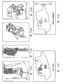
As shown in Fig. 1 (a)-(c), a kind of radiotherapy system 100 of routine comprises a 4-25MV clinac 102 and a collimator 104, described collimator 104 is used to make radiation field 106 collimations that are directed on the patient 108 and is shaped, and patient 108 is supported on the diagnosis and treatment platform 110 and is in a specific treatment position.Treatment comprises by the 114 pairs of focuses of beam of radiation that are positioned at the focus 112 of target area along patient 108 one or more theta alignment on every side shines.In therapeutic process, can use a kind of imaging device 116 to make radiation field 118 imagings through patient 108.Can before treatment, use the imaging device 116 that can make radiation field 118 imagings with the attitude of checking the patient and/or the image that in therapeutic process, writes down the actual emanations field that is transmitted.Usually, such image has very poor contrast resolution and image with respect to the bony landmark of field edge is provided at most.
Another example that is used for reducing the probabilistic known online imaging system relevant with the system of lesions position and/or change at random is an X ray cone-beam computerized tomography scanning system.The CR scanning system of a kind of mechanically actuated of cone-beam computerized tomography scanning system and a kind of routine similar, difference are, utilize single rotation of source and detector to obtain a complete volumetric image.This can utilize a kind of two dimension (2-D) detector different with 1-D detector used in conventional CR scanning to realize.Under a kind of geometry of conical surface bundle, there be the restrictive condition relevant with image reconstruction.But, can utilize the track of improved source known to a person of ordinary skill in the art and detector to solve these restrictive conditions usually.
As mentioned above, a kind of cone-beam computerized tomography scanning system is utilized a plurality of two dimension (2-D) projected image reconstruct three-dimensional (3-D) images that obtain with the different angles around objective body.Utilize the method for the 3-D of 2-D reconstruction from projection image and used method in the CR scanning system of routine to differ widely.In the CR scanning system of routine, according to one or more 2-D lamella (slice) of one dimension (1-D) reconstruction from projection of patient, and these lamellas can " be piled up " to form patient's a 3-D image.In the cone-beam computerized tomography scanning system, utilize the complete 3-D image of a plurality of 2-D reconstruction from projections.The cone-beam computerized tomography scanning system has a plurality of advantages, and these advantages comprise: utilize the 3-D image (and conventional CR scanning system needs the rotation of each lamella usually) that forms the patient around single rotation of patient; Be essentially isotropic spatial resolution (and in the CR scanning system of routine, spatial resolution can be subjected to the restriction of lamellar spacing usually longitudinally); And has sizable motility in image geometry in form.Such technology has been used for the application such as the scanning of microcomputer x-ray tomography, when for example, rotating (for example turning over 180 or 360 degree) at the objective body that needs imaging, uses a kind of k VX ray tube and radioscopic image reinforced pipe to obtain the 2-D projection.In addition, the cone-beam computerized tomography scanning system has been successfully used in the medical applications, such as the CR scanning angiography, uses a kind of kV X-ray tube and radioscopic image reinforced pipe on the C shape arm that is installed in a rotation.
Developed a kind of kV cone-beam computerized tomography scanning imaging system that is used for on-line computer x-ray tomography scanning guiding.This system comprises kV X-ray tube and the radiographic detector on the stand that is installed in a clinac.This imaging detector is based on a kind of and low-noise charge coupling device (CCD) the fluorescent screen optical coupling.Very low coupling efficiency (10 between fluorescent screen and CCD
-4) reduced the detective quantum efficiency (DQE) of this system widely.Although this system can produce the cone beam computerized tomography images that quality is enough to observe the soft tissue relevant with prostate radiation therapy, the radiological dose that low DQE needs imaging greater than the required 3-4 of the system that has effective coupling (for example-50% or better) between screen and detector doubly.
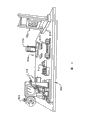
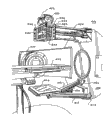
Another example of known auxiliary cone beam computerized tomography scanning imaging system has been shown among Fig. 2.This auxiliary cone beam computerized tomography scanning imaging system 200 utilizes a kind of flat-panel imager to replace the imager based on CCD shown in Fig. 1 (a)-(c).Particularly, this imaging system 200 comprises a kilovolt X-ray tube 202 and a flat-panel imager 204, flat-panel imager 204 has an array that is made of the non-crystalline silicon detector, it is bonded in the geometry of a radiotherapy transmission system 206, and radiotherapy transmission system 206 comprises a MVX radiographic source 208.Also can bestow and use second flat-panel imager 210 in the system 206 at radiotherapy.When patient 214 lay on the diagnosis and treatment platform 216 and is in treatment position, such imaging system 200 can be carried out projection ray to the focus in the target area 212 and be taken a picture and/or successive fluoroscopy.If imaging system 200 is known with respect to the geometry of system 206, can utilizes resulting kV projected image to change patient's attitude so and also improve radiocurable precision slightly.But such system 200 can not provide the observation that is fit to soft tissue structure, therefore is restricted aspect the error that causes owing to the organ movement reducing.
Therefore, one object of the present invention is, produce the kV projected image in a kind of cone-beam computerized tomography scanning system, this cone-beam computerized tomography scanning system can provide the observation that is fit to of soft tissue structure to reduce owing to the organ movement causes error in radiotherapy.
Summary of the invention
One aspect of the present invention is about a kind of radiotherapy system, and this system comprises: radiation source, and described radiation source moves and beam of radiation is directed on the objective body along a paths; And cone-beam computerized tomography scanning system.Described cone-beam computerized tomography scanning system comprises: x-ray source, described x-ray source with the form of conical surface bundle towards the described objective body emitting x-ray that needs imaging; And the non-crystalline silicon flat-panel imager that after X ray passes objective body, receives X ray, described imager provides the image of described objective body.A computer links to each other with described cone-beam computerized tomography scanning system with described radiation source, it is characterized in that, described computer receives the image of described objective body, and transmits signal to control the described path of described radiation source based on described image to described radiation source.
According to another aspect of the present invention, the invention provides a kind of method with an objective body of radiation therapy, described method comprises: along a path movement radiation source; The beam of radiation that will come from radiation source is guided on the objective body; And with the form head for target body emitting x-ray of conical surface bundle.This method also comprises: detect the X ray that passes described objective body owing to described emitting x-ray with the non-crystalline silicon flat-panel imager; Produce the image of described objective body according to the X ray that is detected; And the described path of controlling described radiation source according to described image.
Each aspect of the present invention provides such advantage, promptly, produce the kV projected image in a kind of cone-beam computerized tomography scanning system, this cone-beam computerized tomography scanning system can provide the observation that is fit to of soft tissue structure to reduce owing to the organ movement causes error in radiotherapy.
It is a kind of by being combined in a kind of cone-beam computerized tomography scanning imaging system in the therapeutic room and improving the equipment and the method for radiocurable precision according to the current and follow-up treatment plan of 3-D image modification that the cone-beam computerized tomography scanning imaging system is produced that each aspect of the present invention provides.
Each aspect of the present invention has presented significant variation in implementing radiation therapy process.Not only be used for radiocurable high accuracy, image guidance system and satisfied current utilization and increase the needs that radiological dose improves the probability of healing, and it provides the probability of the extensive innovation in clinical implementation.
Each aspect of the present invention allows selectable segmentation course of treatment, allows the short course of treatment and allows improved combination in the auxiliary treatment mode.
Each aspect of the present invention provides the valuable image-forming information that is used for guided radiation treatment, also provides a kind of clear and definite 3-D to dispose record, disposes success or the failure that treatment can be estimated in record according to 3-D, for the control disease method provides new understanding.
From below in conjunction with finding out other purposes of the present invention, advantage and feature significantly the description of accompanying drawing and the following claim book.
Brief description of drawings
Fig. 1 (a)-(c) shows a kind of geometry and work of traditional radiation therapy equipment;
Fig. 2 shows a kind of perspective view of known radiotherapy equipment, and described equipment comprises an auxiliary facilities that is used for the cone-beam computerized tomography scanning imagery;
Fig. 3 is the sketch of the platform top formula cone-beam computerized tomography scanning system of the related use flat-panel imager of first embodiment of the invention;
Fig. 4 is the geometry of the cone-beam computerized tomography scanning system shown in Fig. 3 and the sketch map of program;
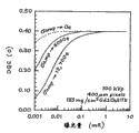
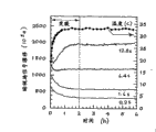
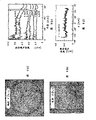
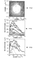
Fig. 5 (a)-5 (d) shows the chart of the key property feature of the flat-panel imager in the cone-beam computerized tomography scanning system that is used among Fig. 3;
Fig. 6 (a)-6 (d) shows the used various article of test in the performance that is used for studying cone-beam computerized tomography scanning system of the present invention, comprise six low contrast inserts in uniform water drum, the tank respectively, have under the tension of tank steel wire and by painless lethal mouse;
Fig. 7 (a)-7 (d) shows the concordance of the response of cone-beam computerized tomography scanning system of the present invention, comprise respectively volume reconstruct by even tank radially, arrowhead section, radially molded lines and vertical signal molded lines;
Fig. 8 (a)-8 (d) shows the noise characteristic of cone-beam computerized tomography scanning system of the present invention, comprises axial and arrowhead noise image, radially the noise molded lines and the vertical noise molded lines of the volume reconstruct that comes from even tank respectively;
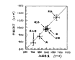
Fig. 9 (a)-9 (b) shows the linearity and the voxel noise of the response of cone-beam computerized tomography scanning system of the present invention and traditional computer x-ray tomography scanning means respectively;
Figure 10 (a)-10 (c) shows the noise power spectrum that comes from cone-beam computerized tomography scanning system of the present invention, comprise the gray level curve of axial noise power spectrum respectively, in various position to the noise power spectrum of measured noise power spectrum and the cone-beam computerized tomography scanning system compared with traditional computer x-ray tomography scanning means;
Figure 11 (a)-11 (b) shows the spatial resolution of cone-beam computerized tomography scanning system of the present invention, be included in the thin steel wire shown in Fig. 6 (c) the axial slice image surface curve and be respectively the cone-beam computerized tomography scanning system and the measured modulation transfer function (MTF) of traditional computer x-ray tomography scanning means;
Figure 12 (a)-12 (b) shows the image of the low contrast radiation simulator that is obtained respectively from cone-beam computerized tomography scanning system of the present invention and traditional computer x-ray tomography scanning means;
Figure 13 (a)-13 (i) show shown in Fig. 6 (d) by the cone beam computerized tomography images of painless lethal mouse, comprise lungs district (Figure 13 (a)-13 (c)), kidney district (Figure 13 (d)-13 (f)) and bottom vertebral region (Figure 13 (g)-13 (i));
Figure 14 (a)-14 (d) shows being drawn by the volume data of the cone beam computerized tomography images of painless lethal mouse shown in Fig. 6 (d) to scheme, the spatial resolution degree that obtained in constructing described at vertebra has been described, has comprised respectively: shown having axially and the volume data drafting figure of arrowhead section, having the volume data drafting figure of axial and radial section, only the window of skeleton character, spinal column and the enlarged drawing of rib region and the enlarged drawing of 1/2nd vertebras of mouse be shown of the soft tissue structure of abdominal part and skeletal tissue;
Figure 15 (a)-15 (b) shows the axial image of the euthanasia mouse shown in the Fig. 6 (d) that is obtained respectively from cone-beam computerized tomography scanning system of the present invention and traditional computer x-ray tomography scanning means;
Figure 16 shows the chart as calculated detective quantum efficiency of the function of the light exposure of present and ideal flat-panel imager structure;
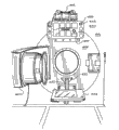
Figure 17 (a)-(e) is several angular orientation sketch maps of the wall-mounted cone-beam computerized tomography scanning system of the related use flat-panel imager of the second embodiment of the present invention;
Figure 18 shows when using first embodiment of the used support member of flat-panel imager involved in the present invention, the side view of the cone-beam computerized tomography scanning system among Figure 17;
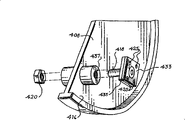
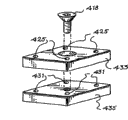
Figure 19 (a) shows the perspective exploded view of the installing component that is used in combination with the used support member of the flat-panel imager of Figure 18;
Figure 19 (b) shows the decomposition diagram of the rotational engagement parts that are used in combination with the installing component of Figure 19 (a);
Figure 20 (a)-(b) schematically shows when using second embodiment of the used support member of flat-panel imager involved in the present invention, the front view of the wall-mounted cone-beam computerized tomography scanning system shown in Figure 17;
Figure 21 (a)-(b) schematically shows when using the 3rd embodiment of the used support member of flat-panel imager involved in the present invention, the front view of the wall-mounted cone-beam computerized tomography scanning system shown in Figure 17;
Figure 22 is to use the sketch of the portable cone-beam computerized tomography scanning system of the related flat-panel imager of fifth embodiment of the invention;
Figure 23 (a)-(d) shows the geometry of the cone-beam computerized tomography scanning system shown in Figure 17-22 and the sketch map of work;
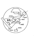
Figure 24 shows the flow chart of an embodiment that the cone-beam computerized tomography scanning system of utilizing among Figure 17-22 obtains the correlation technique of cone-beam computerized image;
Figure 25 shows the perspective view of embodiment of a method of the geometric calibration of the imaging that is used for Figure 17-22 and treatment transmission system; And
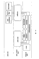
Figure 26 shows the flow chart according to the embodiment of the relative program of the radiotherapy system of the image guiding in Figure 17-22 of the off-line modification of a patient's cone beam computerized tomography images, attitude error and organ movement's on-line correction and treatment plan subsequently.
The preferred embodiments of the present invention
Related platform top formula cone-beam computerized tomography scanning (CBCT) system 300 of one embodiment of the present of invention has been shown among Fig. 3.The structure simulates of this CBCT system 300 is installed on the geometry of the CBCT scanning means on the linear accelerator at present, and the distance of source-axis is 1000mm, and the distance of source-detector is 1600mm.The critical piece of this system 300 comprises: X-ray tube 302, turntable 304 and flat-panel imager (FPI) 306.These parts are installed on optical bench 308 rigidly.The relative position of these parts is controlled by three travelling carriages, and these travelling carriages comprise x Target Station 310, y Target Station 312 and y figure entablement 314, and they are used for initial setting up and accurately determine and be controlled to look like geometry.Cone-beam computerized tomography scanning system 300 produces the image of objective body 316, and described objective body is discerned with the radiation simulator all the time, and described objective body 316 is installed on the turntable 304.Each 310,312 and 314 all comprises and resetting or limit switch, and described picture geometry is that position with these switches is a benchmark, and reconstruct is ± 0.01mm.Illustrated among Fig. 4 and described concrete geometry used in the content here, and made described concrete geometry imitate the used picture geometry of cone-beam computerized tomography scanning system that is combined on the radiotherapy equipment.Following table 1 shows the parameter of system 300.
One group of locating laser device 318 makes pivot center 320 visual, and the plane, source is perpendicular to pivot center 320 and with x-ray source or manage 302 focus 322 and intersect.Make pivot center 320 so locate, that is, make itself and central ray 324 between focus 322 and detector plane 326 intersect (+0.01mm).Make flat-panel imager 326 so locate, promptly, with crossing point (just, the cross point of central ray and imaging plane) be imaging array the center (just, between row #256 and the #257, ± 0.01mm), have the skew of 1/4th pixels to provide the improvement image pattern of cone-beam computerized tomography scanning collection, wherein make 360 ° of objective body 316 rotations.With described 310 of micrometer artificially, location control.Determine source-objective body distance (SOD) and source-image distance (SID) in ± 0.5mm scope and set 1.60 target magnification, equal the target magnification of the imaging system on the linear accelerator.The cone angle of this geometry is-7.1.
X-ray tube 302 (such as General ElectricMaxi-ray) and 100kW generator (such as General Electric MSI-800) with 300kHU under computer control produce the X-ray radiography light exposure that is used for this capture program.Pipe is 302 for the total minimum filter action with 2.5mm A1, and the filtering with additional 0.127mm Cu is with further reinforcement beam, and has the specified focus that is of a size of 0.6mm.The feature of 100kY beam is respectively 5.9 and first and second HVLs of 13.4mm A1.In the time in a week to the accelerating potential of generator monitor and find described accelerating potential be stabilized in ± 1% scope in.(such as the RTI Electronics that has the silicon diode detector, Model PMX-III) determines all light exposures with the X ray circuit tester.
According to the light exposure that under the situation that does not have target 316, is used for the cone-beam computerized tomography scanning collection with respect to the light exposure report of air at turning cylinder 320 places.The image that the same quadrat method of report light exposure can be used on the conventional scanner being obtained.For conventional scanner, by stand not being rotated and set the lamellar spacing of 10mm for collimator, thereby guarantee the covering fully of silicon diode, measure the light exposure of per unit electric charge.For platform top formula and conventional scanner, the light exposure of the per unit electric charge under the 100kVp is respectively 9.9mR/mAs and 14.9mR/mAs.
Flat-panel imager 306 can be the EG﹠amp of 512 * 512 arrays that comprise Si:H photodiode and thin film transistor (TFT); G Heimann Optoelectronics (RID 512-400AO).The electro-mechanical characteristic of imager has been shown in table 1.Read flat-panel imager 306 with eighth present frame frequency (per second is up to 5 frames), and the master computer 328 that schematically shows in the asynchronous ground application drawing 4.The ASIC amplifier that is characterized as relevant complex sample noise reduction circuit carries out integration to the analogue signal that comes from each pixel.Realize digitized at 16 bit resolutions.Transmit this numerical value via the hardware buffer of RS-422 bus in master computer 328.When preparing, interrupt the processor in the master computer 328 to main storage transmission whole frame.
Table 1
| The CBCT feature | Numerical value |
| Obtain geometry | |
| Source-axle-distance (S AD) | 103.3cm |
| Source-imager-distance (S ID) | 165.0cm |
| Cone angle | 7.1° |
| The maximum angular velocity of rotation | 0.5 °/second |
| Field of view (FOV) | 12.8cm |
| X-ray beam/light exposure feature |
| Beam energy | 100kVp |
| Additional filtering | 1.5mm A1+0.129mm Cu |
| Beam quality | HVL 1=5.9MM A1 |
| HVL 2=13.4MM A1 | |
| Scattering and initial ratio | 0.18,1:5 (11cm objective body) |
| Frame time | 6.4 second |
| Pipe output (SAD) | 9.34mR/mAs |
| Exposure rate (SID) | 3.65mR/mAs |
| Flat-panel imager | |
| Title | RID 512-400 |
| Array format | |
| 512 * 512 pixels | |
| Pixel pitch | 400μm |
| The CBCT feature | Numerical value |
| The zone | ~20.5 20.5cm 2 |
| The pixel duty factor | 0.80 |
| Photodiode charging volume | ~62pc |
| ASIC amplifier charging volume | ~23pc |
| The ASIC amplifier noise | ~12,700e |
| The ADC bit-depth | 16 bits |
| TFT thermal noise (on) | ~1800e |
| Photodiode shot noise (1fps) | ~1200e |
| The digitized noise | ~630e |
| Specified frame frequency | 0.16fps |
| Maximum frame rate | 5fps |
| The X ray transducer | 133mg/cm 2Gd 2O 2S:Tb |
| The acquisition program | |
| The quantity of |
300 |
| Angle increment | 1.2° |
| Total rotational angle | 360° |
| The maximum angular velocity of rotation | 05 D/s |
| Reconstruction parameter | |
| Restructuring matrix | 561×561×(1- 512),281×281×(1-500) |
| Voxel size | 0.25×0.25×0.25mm2,0.5×0. 5×0.25 |
| The CBCT feature | Numerical value |
| W. parameter | 1.60 |
| γ, cut-off frequency changes | 1.0 |
| α, the Hamming filter parameter of change | 0.50 |
| The scope of circling round | ±25mm |
Conical surface bundle scanning imaging system comprises that radiographic exposure, array read the repetitive sequence of rotating with objective body.Nonsynchronous frame clock pulses that the time limit of this program is read electronic equipment by flat-panel imager drives.Adopt the constant frame clock pulses of 6.4s.During periodic frame was carried from flat-panel imager 306, master computer advanced vehicularized turntable 304 and starts x ray generator or manage 302.The rotor of X-ray tube 302 keeps rotation in whole scanning imaging system.Control software makes the number of frames of operator between can the regulation exposure period.It is designed to be able to study the mechanism that reduces the method for hysteresis in follow-up projection.Monitoring comes from detector signal in the exposed beam zone of flat-panel imager 306 be made of nine pixels one group so that measure and check the stability of each radiographic exposure.Collect (trap) and repeat the outer light exposure of tolerance limit with same projectional angle.Each projection image is write hard disk between frame transmission and revolution.After having obtained projection, one group of general source developing and dark field image (each 20) are collected so that handle to constitute for the flat field of projection image and amplify and the image of skew.
Except amplification and offset correction, carry out central filtering (3 * 3) with the pre-pie graph of unstable pixels.Finally, with the little deviation of the signal normalization in each projection with explanation X ray light exposure, this is by bunch execution said procedure of nine pixels in the detector periphery of objective body shadow external.
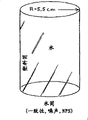
With back projection's technology of filtering according to reconstruction from projection's volume calculation machine x-ray tomography scan-data group.Use Webb ' s three parameter formula to be configured for wave filter in this reconstruct.Described parameter and corresponding numerical value thereof have been shown in table 1.In present structure, it is the cylinder that 12.4cm, length are approximately 12.1cm that reconstruction visual field is constrained to diameter; The lateral length for the treatment of the objective body of reconstruct must be put just and be placed in this cylinder.With the voxel numerical value in the resulting volumetric set linearly convergent-divergent to produce average CT number (being 0, is 100) in water in air.With required time on single projection filtering (Unit 100 nuclear) and back projection to 281 * 281 * 500 voxel data groups is 1 minute and 21 seconds.
The baseband signal of assay plate imager 306 and noise characteristic.In Fig. 5 (a), the detector gain and the linearity have been provided.For the X ray beam energy of 120kVp, the detector gain of mensuration is 18.2 * 10
5/ mR/ pixel (is 17.8 * 10 under 100kVp
6/ mR).Detector demonstrates the splendid linearity, and light exposure is up to 50% of its sensitive volume (5mR).Various additional electronic noise sources and amplitude thereof in table 1, have been listed.We find that total additional electronic noise depends on frame time, and its scope is 13 from the frame time of 200ms, and 300e is 22 to the frame time of 25.6ms, 500e.Amplifier noise (12,700e) be the key component of high frame frequency.Can study the importance of the amplifier noise on the zero frequency detective quantum efficiency (DQE), described cascade system model analysis signal and noise transmission in FPI306 with the cascade system model.
Fig. 5 (b) shows and is used for RID 512-400 AO and two and has reduced the light exposure of ideal image device of amplifier noise with respect to the relation curve of detective quantum efficiency.The basic quantum efficiency that is used for detector is approximately 0.57; For the light exposure more than the 1mR, the loss that causes owing to energy absorption noise and additional source make detective quantum efficiency be reduced to~0.41.For the light exposure that is lower than 0.1mR, the detective quantum efficiency of amplifier noise values and EG﹠amp; That is found in the G detector compares rapid reduction.So far, thicker/fine and close objective body [for example, pelvis (~30cm water)] causes detector, and (radiological dose for example ,~0.001mR) obviously reduces amplifier noise (and/or X ray transducer, for example Csl; T1) improvement will obviously improve detective quantum efficiency.
The temporary transient stability of detector blurred signal has been shown in Fig. 5 (c).This curve is corresponding to selected group of the pixel of " typical case ".Blurred signal changes significantly during a 2h of operation, and described blurred signal variation is interrelated with the temperature change in the flat-panel imager obturator.After temperature stabilization, blurred signal is also stable.Based on these factors, the array energising after at least two hours, could carried out all cone-beam computerized tomography scanning.In some zone of array, even after thermal balance, blurred signal is still unstable.Suppose that these zones are the results that occur deviation in the array fabrication schedule.
Continually varying in the CR scanning resembles the width of cloth need have the detector of reading at a high speed with minimum temporary transient fuzzy (or " hysteresis ").These features have been determined with short frame internal X-ray exposure.Fig. 5 (d) shows the pixel signal after frame number is 0 o'clock the interim single radiographic exposure that applies of collection.Frame has subsequently shown the delay signal of frame number 1 to 9, scope from~4% to~0.04%.Notice that this hysteresis has shown that non-is interesting and important based on the curve of frame number only but based on frame time.
Before reconstruct, with projection correction with obtain the skew and increment aspect fixed pixel-pixel variations.The defective pixel that has obvious deviation or have an abnormal signal response in the dark field signal is carried out medium filtering.Before reconstruct, use the auxiliary resulting projection of 128 row paddings (pad).The form of following delegation with delegation is set at meansigma methods at 7 pixels at described array periphery place with the pixel value of being clogged.At last, for the little deviation in the X-ray tube output is described, the signal that utilization records from above-mentioned naked beam monitor pixel (9 pixel) makes the signal normalization in each projection.Can 250MHz UltraSparc processor (such as Enterprise450, SunMicrosystems, Sunnyvale CA) go up to carry out this pre-reconfiguration program.
The backprojection operation rule of the filtering of Feldkamp can be used for the reconstruct data group.On the flute card matrix of 561 * 561 * N voxel, wherein the numerical value of N of lamella depends on the objective body of being paid close attention to image reconstruction.The voxel size that is used in these reconstruct is generally 0.25 * 0.25 * 0.25mm.Be used in filtering in this reconstruct and follow the formal system of Webb.Table 1 has comprised and has limited three parameters that are used in the wave filter in these researchs.After finishing described reconstruct, skew and zooming parameter are constant for 9mm reconstruct and set of acquisition parameters.Also can in the UltraSparc system, carry out the reconstruct of volume cone-beam computerized tomography scan-data group.
Study the concordance of the response of imaging system 300 on three-dimensional (3-D) above field of view (FOV) by the imaging of cylindrical tank (diameter is 110mm).On conventional scanner, also obtain identical radiation simulator scanning.Along radially detecting described response with vertical molded lines by institute's reconstructed volume.
Research is as the noise of the reconstructed image of the tank of X ray light exposure function.With 131,261,653,1310,3260 and the light exposure of 6530mR obtain image.On 561 * 561 * 11 matrix, wherein the voxel size on the side is 0.25mm with image reconstruction.For all reconstruct, reconfigurable filter is decided to be parameter defined in the table 1.Change these parameters and can produce significantly influence the noise characteristic of reconstructed image.With the analytic process of standard deviation in the CT number in 5 * 5 * 1 zone of running through data set, and analyze the noise characteristic of these image collection by the noise power spectrum that calculating comes from the 3D data set.Carry out these analytic process as the light exposure function.The uniformity of the noise by detecting all 3-D data sets is evaluated the relative stability of described noise.These results show that the noise characteristic of described data set is only along with the slight variation in position.Because stability is the noise power effect just when the essential condition of decipher,, these baseline results provide support so being the application of noise power spectrum.
Analyze noise power spectrum by the expansion cause volume data that uses known 2-D projected image analytical method.Make volume data normalization, so that the average CT number in the water vat is 1000.From volume, draw the square area (256 * 256 * 20 voxel) in the water vat, and a spot of voxel defective (usually<1%) is carried out 3 * 3 medium filtering.Astringent 2-D center lamella for the Fourier transformation that obtains 3-D makes 20 lamellas average along the z-direction, and finds, more lamella on average do not influence noise power spectrum, that is to say that its data are astringent.In order to reduce background trend, in an independent scanning, deduct average formed background lamella by 81 lamellas.Deduct the plane that is suitable for data and can further reduce low frequency trend, the realization that produces the 2-D zero-mean.Set according to 16 64 * 64 Non-overlapping Domain from described realization calculates two-dimensional fast fourier transform (FFT), and the result is average.Make described normalization as a result so that explanation voxel size and be averaged, and the volume under the noise power spectrum is compared with the square value of standard deviation by z.Resulting noise power spectrum is represented (U
XU
Y) center lamella in the territory, just, with (x, y) Fourier's correspondence in territory.In order to show that the 1-D power spectrum is along U
XAxle will be with NPS (U
X) extract NPS (U out
X) for example be various exposure magnitudes.
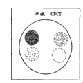
The noise characteristic of cone-beam computerized tomography scanning system 300 is compared with the noise characteristic in the traditional computer x-ray tomography scanning means.In order to make contrast meaningful, these two systems must show same response in the deviation of signal scope.By response as described in detecting with these two system scan electron densities radiation simulators (as shown in Fig. 6 (b)).Seven inserts of its coefficient near water coefficient are inserted in the tank that diameter is 110mm.This insert is to take out from the RMI electron density radiation simulator with normal CT number.In Fig. 6 (b), from the top by being clockwise: CT hard water (CT#1001), BR-SRI chest (CT#945), BRN-SR2 brain (CT#1005), C133 resin compound (CT#1002), LV1 liver (CT#1082) and polyethylene (CT#897).Under equal light exposure and kVp, form the image of radiation simulator with cone-beam computerized tomography scanning system 300 and conventional scanner.
The attenuation quotient (with respect to water) that cone-beam computerized tomography scanning system 300 is write down is compared with the coefficient that conventional scanner is write down.Calculate first rank that are suitable for measurement data to determine the relative linearity of these two systems.Also determine the noise characteristic of conventional scanner, under 100kVp, utilize thickness to obtain image down in four exposure magnitudes (743,1490,2970 and 5940mR) for the lamella of 1mm with above-mentioned water vat test radiation simulator.Under each exposure magnitude, obtain three images.On conventional scanner, carry out reconstruct with " High Res Head (#1H) ", " Standard Head (#2) " and " Smooth Abdomen (#3) " wave filter.Noise analysis is consistent with the noise analysis that is applied to cone-beam computerized tomography scan-data group.For the noise result of relatively in each system, determining, repeat the analysis of cone-beam computerized tomography scan-data group, the meansigma methods of wherein at first trying to achieve the cone-beam computerized tomography scan-data on 2 * 2 * 4 voxels is to produce and the given voxel size that is equal to (0.5 * 0.5 * 1mm ') of conventional scanner.
As shown in Fig. 6 (c), utilize the spatial frequency transmission characteristic of tinsel test target body measurement cone-beam computerized tomography scanning system 300.The test target body comprises that the diameter that is suspended in the tank that diameter is 50mm is the steel wire of 0.254mm.Form the image (at 100kVp) of radiation simulator on cone-beam computerized tomography scanning system 300, wherein tinsel is the center with pivot center 320, and the distance between tinsel and the axis is 30mm.With the described wave filter of table 1 with resulting image reconstruction at 0.1 * 0.1 * 0.25mm
3On the high-resolution reconstruction grid.With six adjacent sheets (thickness of each is 0.25mm) on average to produce low noise point scattering function (PSF).By the at first Radon conversion of calculation level scattering function (just) along x axle or y axle integration, then calculate the 1-D Fourier transformation, calculate quadrature lamella by the 2-D modulation transfer function (MTF).Make each 1-D molded lines normalization so that the zone is consistent.Apply the limited diameter of correction,, under 100kVp, the thick lamella of 1.5mm is carried out identical test on conventional scanner for relatively with the compensation steel wire.With three different reconfigurable filters [" High ResHead (#1H) ", " Standard Head (#2) " and " Smooth Abdomen (#3) "] reconstructed image.
Come the dependent imaging performance of comparison cone-beam computerized tomography scanning system 300 and conventional scanner with radiation simulator and toy.Carry out the simple comparison of soft tissue power of test with the radiation simulator shown in Fig. 6 (b).Proximity in the CT number between six cylinders makes this radiation simulator become useful object of experiment body to detect contrast sensitivity and soft tissue detectability, obtains the image of radiation simulator with cone-beam computerized tomography scanning system 300 and conventional scanner.The lamella (1.5mm) that multiple high-resolution cone-beam computerized tomography scanning lamella on average is equivalent to be used in the thickness on the conventional scanner with generation.In two kinds of different scanning devices, use equivalent light exposure (2980mR) and kVp.
In Fig. 6 (d),, implement painless causing death for described mouse for other purposes by the imaging of laboratory mouse being carried out second test of soft tissue sensitivity.Use scanning imaging system same as described above, carry aerial, the light exposure on axis of 2980mR for each system.With 0.25 * 0.25 * 0.25mm
3The resulting 3-D data of voxel size reconstruct.Also on traditional computer x-ray tomography scanning means, scan this theme with the thick lamella of 1.5mm.The same imaging radiological dose that this scan transfer and cone-beam computerized tomography scanning system 300 are transmitted.In order to compare mutually, six lamellas that will come from cone-beam computerized tomography scan-data group are on average with the lamella of the lamellar spacing equivalent that produces its thickness and conventional scanner.Can compare display imager under form and the magnitude so that compare.
The concordance of the response of cone-beam computerized tomography scanning means has been shown in Fig. 7 (a)-7 (d).Wherein show lamella by the axial and arrowhead (sagittal) of cone-beam computerized tomography scanning 3-D data set.More consistent response on the whole visual field of the clear system of image table.In the block diagram equilibrium region of image, can see the slight discordance of about 20CT number (2%).Described discordance shows as compound indentation (cupping) and covers the artificiality of (capping).Radially molded lines (Fig. 7 (c)) further shows this point by comparing with result's (chain-dotted line) that conventional scanner is obtained.The internal inspection of the reconfiguration program that carries out with analog projection data shows that discordance is the artificiality of reconfiguration program and the selection of depending on filtering parameter.Except for the inherent discordance of reconstruct, the response of cone-beam computerized tomography scanning system 300 is highly consistent, especially along z-to.
Except the concordance of the response that shows system, the image among Fig. 7 also shows the consistent noise characteristic that has a small amount of artificiality.This shows the gamut of light exposure research.The magnitude and the concordance of noise have been shown in Fig. 8 (a)-8 (d).Described noise changes a small amount of angle and changes negligible angle along vertical axis along longitudinal axis.Because difference aspect the transmission of passing cylindrical tank, can expect dependency slightly with respect to radial position.Fig. 8 (c) has also represented the dependency [with respect to Fig. 9 (b), below also illustrate] of noise with respect to the mensuration of light exposure.Generally speaking, for light exposure in the air of the 6560MR at isocenter place, cone-beam computerized tomography scanning system 300 can reach the noise level that is approximately the 20CT number.
In the upper end curve of Fig. 9 (b), illustrated and be cone-beam computerized tomography scanning system 300 determined noises as the light exposure function.We see that noise is reduced to-20 units of highest point from-80 units of the lowest exposure amount that detected.Stack is square match of following form at least:
Wherein σ is that the noise in the voxel value, airborne light exposure, a and the b that X is the isocenter place are the constants that is obtained from digital match.The basic noise transmission principle unanimity of negative square root relevant and the reconstruct of x-ray tomography radiography with light exposure.
For the linearity and the degree of accuracy of detection system response, the CT number that cone-beam computerized tomography scanning system 300 is reported for multiple material (Fig. 6) is compared with the CT number that conventional scanner is reported.As shown in Fig. 9 (b), the CT number of cone-beam computerized tomography scanning system 300 is more consistent with the CT number of conventional scanner.Deviation maximum on the scope of CT number is 8 units, and its average deviation is 5.7.The high coefficient of mutual relation is represented, and is on the scope that is detected, proportional by 300 values reported of cone-beam computerized tomography scanning system and attenuation quotient.
Voxel noise contrast as cone-beam computerized tomography scanning system 300 with the conventional scanner of light exposure function has been shown in Fig. 9 (b).Open the result of the conventional scanner of circle and represented being to use of dotted line " High Res Head (#1H) ", " Standard Head (#2) " reconfigurable filter.In each case, noise reduces with light exposure.Accurate contrast between these two kinds of systems requires under equal voxel size and uses same reconfigurable filter to come the reconstruct data group.Noise analysis by repeating cone-beam computerized tomography scanning system 300 and with volume data on average to provide the voxel size that is equal to scanning means, can realize the requirement of equal voxel size.
For reconfigurable filter being shown, carry out reconstruct with " High Res Head " and " Standard Head " reconfigurable filter to the voxel effect of noise.The low block curve that has synergetic least square fit shows the noise of cone-beam computerized tomography scanning system 300 under equal voxel size.Under equal voxel size, clearly, cone-beam computerized tomography scanning system 300 has the higher noise of result than " Standard Head " CR scanning device under low light exposure, yet, compare with " High ResHead " result of conventional scanner, in fact cone-beam computerized tomography scanning system 300 is except all demonstrating lower noise under the very high light exposure.Far and away, require the careful coupling of reconfigurable filter and restructuring matrix so that allow accurately comparing mutually of these two kinds of systems.However, because the known early stage typical flat-panel detector that is used in this system demonstrates higher additional electronic noise, exceed the coefficient of 5-10 than the design of recent electronics, so the result who is obtained with cone-beam computerized tomography scanning system 300 is inspirer.
In Figure 10 (a)-10 (c), summed up the result that noise power spectrum is measured.2-D noise power spectrum in the axial plane (Figure 10 (a)) demonstrates the spectral shape standard of the system that adopts backprojection reconstruction filtering.Spectral density is reduced (but non-zero) near zero frequency because slope (ramp) wave filter (for example, at-0.5mm
-1Increase severely on every side) and increase at intermediate frequency, and tilt when higher frequency by the lowpass noise feature (for example, the selection of 2-D image diffusion and apodization form) of system.In Figure 10 (b), show for various exposure magnitudes along u
xTo the lamella of noise power spectrum.Because for various situations have been determined average signal level (just, within the CT#=1000 water radiation simulator), along with the increase noise power spectrum of exposure reduces.Particularly, noise power spectrum presents situation about being inversely proportional to the exposure that meets the digital match form among Fig. 9 (b) reluctantly.As shown in Figure 10 (c), the noise power spectrum of being measured at-1.3R (in air at the isocenter place) is near zero-frequency-30mm
3,, then when Nyquist frequency, drop to the initial level that is approximately spectral density owing to increase coefficient-4 at intermediate frequency.
Stack among Figure 10 (c) is the measured result of conventional sweep device who utilizes three reconfigurable filters, and for the ease of stack, for an equal voxel size, shows the noise power spectrum of cone-beam computerized tomography scanning system 300.For #2 and #3 wave filter, the conventional sweep device has shown a kind of noise power spectrum with above-mentioned character shape; But as can be seen, high-resolution #1 wave filter has amplified high-frequency noise widely.Cone-beam computerized tomography scanning system 300 is compared with the conventional sweep device that utilizes #2 and #3 wave filter, shows as the low-frequency noise power spectrum.Suppose, the selection of reconfigurable filter can influence noise and resolution widely, and two kinds of situations that as if consideration mate very much, cone-beam computerized tomography scanning system 300, even in, the non-optimum configuration initial, also show as the noiseproof feature that can provide comparable with the conventional sweep device at it.As can be seen, cone-beam computerized tomography scanning system 300 shows the voxel noise lower than conventional sweep device (#1H) under low light exposure from Fig. 9 (b).Similarly, cone-beam computerized tomography scanning system 300 shows lower high-frequency noise power spectrum.These baseline results are wished to consider in the FPI design especially and are read ongoing improvement in the electronic device.
Figure 11 (a) has represented the response of cone-beam computerized tomography scanning system 300 with respect to tinsel test target body.Briefly say, PSF be symmetric (except with the performance-relevant little striped artificiality of the picture lag of system) and be 0.6 millimeter in the overall with (FWHM) of a peaked half.Figure 11 (b) is for to show the MTF of system in two kinds of tinsel results on the axis and outside axis.These result's suggestions, the frequency of system in the plane of z=0 should not surpass detected relatively little scope (30 millimeters) widely by changing.Also show among Figure 11 (b), in the MTF result of conventional sweep device, proved the strong influence of reconfigurable filter.
" Standard Head (#2) " wave filter is compared with " High Res Head (#1H) " wave filter, and the signal that has reduced system widely passes through.This result proved, when using " High ResHead (#1H) " wave filter, the MTF of conventional sweep device and cone-beam computerized tomography scanning system 300 be comparable.This observation with conform in the noise result shown in Fig. 9 (b).Cone-beam computerized tomography scanning system 300 does not upwards compare at z with the resolution of conventional sweep device.But, can predict that cone-beam computerized tomography scanning system 300 is in z spatial resolution that makes progress and conforming to of measuring on axial plane.Certainly, the spatial resolution of conventional sweep device will be subjected to the restriction of selected lamellar spacing (being generally 1 millimeter or bigger).Approaching isotropic resolution of cone-beam computerized tomography scanning system 300 is considered to detect and a localized significant advantage.
Figure 12 (a) and 12 (b) show the axial image lamella of the low contrast radiation simulator that cone-beam computerized tomography scanning system 300 and conventional sweep device obtained under identical kVp and light exposure.Gray level form under each situation be rather narrow so that the contrast of display degree reaches maximum, although and obviously having the tiny signal nonuniformity for cone beam computerized tomography images (artificiality of above-mentioned covering/indentation), the visibility of each insert and conventional sweep device are comparable.The average signal value of each material is as shown in Fig. 9 (a).Light Difference in system responses (for example, because detector response, X ray frequency spectrum etc.) can cause having the contraction reversing of material of CT# very near water.For example, embed at brain under the situation of (bottom right), even in that (5CT#) difference is enough to be provided at this material with respect to obviously putting upside down in the density of water by small between cone-beam computerized tomography scanning system 300 and the conventional sweep device.The minimum contrast that can detect is that ground superior (for example, the visibility of brain and CB-3 insert) can be discussed for cone-beam computerized tomography scanning system 300, but this still can confirm by a kind of observational study that can better control, equivalence.
Figure 13 (a)-(i) shows the situation of the overall performance of explanation cone-beam computerized tomography scanning system 300 in the image of volumetric set.These images by the euthanasia mouse have proved the soft tissue sensitivity and the high spatial resolution of this system.Show from each zone of whole volumetric set example images (for example lung region (a, b, c) and kidney zone (d, e, f) and following vertebra (g, h, i) in) utilize the quantity and the concordance quality of the data that cone-beam computerized tomography scanning system 300 produces with explanation.Clearly observing soft tissue structure has proved the soft tissue contrast sensitivity of this scanning means.
In Figure 13 (a)-(c), form and energy level have been set to emphasize the feature in the mouse pulmonary.Except lung detail, also have some owing to the obvious striped that artificiality causes, its reason is unknown, but believes and strengthen relevant with detector hysteresis effect or beam.
The soft tissue contrast contrast of cone-beam computerized tomography scanning system 300 has been shown among Figure 13 (d)-(f), and wherein form and energy level have been set to describe fat and muscle.The left kidney position of representing mouse at the cross-wire of each image.These picture specifications describe a advantage such as approaching isotropic spatial resolution of the 3-D structure of kidney.Other structures also can be clear that such as stomach, intestinal and liver.
The spatial resolution performance of system 300 has been shown among Figure 13 (g)-(i), has wherein utilized and select to show the form of skeleton character and the data set that energy level shows same mouse.Can see intervertebral space and non-cortical bone in pelvis well.It should be noted that such readability is to be produced by the cone-beam computerized tomography scanning system 300 of operating on the scale of the geometry of imitating linear accelerator.Therefore, such readability is desired in the clinical implementation of this device, provides the accurate adjustment of mechanical flexure.Also show volumetric set among Figure 14, wherein the volume perspective view has illustrated the full 3-D character of this data set and has shown the readability that is included in the cone-beam computerized tomography scan-data.Interesting is to notice that all data of representing in Figure 13 and Figure 14 all are to utilize the once collection of carrying out in the mode of single rotation to obtain.
At last, by comparing, can estimate the picture quality that produces by cone-beam computerized tomography scanning system 300 with the image that produces by the conventional sweep device.Figure 15 (a)-15 (b) shows the axial slice of the mouse that utilizes two systems' acquisitions.Under the identical situation of light exposure, utilize two images that system produced having comparable quality aspect spatial resolution and the contrast contrast.Show good spatial resolution and provide based on the cone beam computerized tomography images of flat-panel imager soft tissue border and the clear of internal organs details are described.The performance of the spatial resolution of cone-beam computerized tomography scanning system 300 surpasses the conventional sweep device; But, must be noted that the voxel size that restrictive condition limited in effective restructuring matrix of conventional CR scanning device is the twice of cone beam computerized tomography images.Lack tangible pixelation and represent in the cone beam computerized tomography images based on flat-panel imager, readability is represented the physical restriction in the spatial resolution of present system.
The purpose of these researchs is to estimate in a cone-beam computerized tomography scanning system, particularly in the fault radiography imaging system that is used for the radiotherapy guiding on a kind of clinac, with the application performance of plate technique as a kind of detector.
Our research quantitatively and the qualitative results suggestion, be a kind of viable means that the high-performance computer x-ray tomography scans that is used for based on the cone-beam computerized tomography scanning means of flat-panel detector technology.The conforming baseline results of signal response shows that in ± 2%, small nonuniformity shows as bonded covering and the indentation artificiality in the x-y plane in the concordance on the visual field in the response of this system, and this belongs to the reconstruct artificiality.Utilize the scope of soft tissue test material to prove the linearity and the discovery that respond, the linearity is in ± 6%.Picture noise proves with respect to the mensuration of light exposure, template cone-beam computerized tomography scanning system 300 can with the equal mode execution work of conventional sweep device, the negative square root light exposure relation curve of certification theory prediction.Strengthened these conclusions and illustrated that development is used for the advantage of characterizing method of frequency dependence of wider (experiment and theoretical) of volume calculation machine x-ray tomography scanning system for the research of the noise power spectrum of two kinds of systems and spatial frequency response.
Except the detection by quantitative of performance, low image that shrinks the radiation simulator and toy are dissected and have been confirmed the conclusion that obtains from these detections to show fabulous definition and retract soft tissue, can carry out tissue positioned more fully in tumour radiotherapy.
Here Biao Xian result has proved this probability that is used for the means of volume imagery.But, under the condition of little objective body size and small-angle, carried out this research.These conditions are that the size of detector used in this research is given.Utilize big detector imaging to allow to increase cone angle, and, allow to increase the thickness of objective body for CR scanning.Performance based on the result who is showed here can be inferred, must be noted that some problems when utilizing bigger detector to operate.Utilizing bigger visual field that bigger objective body is carried out imaging will increase scattering and reduce transmission.Can predict, increase the scattering meeting because of in the image of reconstruct, introducing nonuniformity (for example, indentation and/or striped (streak)) and the additional X ray quantum noise of adding and the CR scanning imaging performance is exerted an adverse impact in picture signal.The scattering power that reaches detector depends primarily on the cone angle and the air gap of being adopted, and research proposal, uses with conventional radiography and compares, and can be lowered with the scattering of these distances.To the strong and weak problem of X ray scattering quantitatively and development to make the method for its reduction be ongoing research direction.
Except relating to the scattering of X ray under the situation of big cone angle, will reduce the fluence of arrival detector greatly than the scanning of general objective body.Transmit to weaken the performance to flat-panel detector is exerted an adverse impact.The performance that present spendable flat-panel imager shows is lower than the normal image intensifier with the film speed operation of fluoroscopy, and this is to have additional noise in the electronic device owing to reading at flat board.Additional noise makes the detective quantum efficiency of imager depend on the quantity of the X ray that forms an image.In these research used flat-panel imager 306 has been shown among Figure 16 and has been embodied in the performance curve of the desirable detector of latest developments in the design of imager 306, nearest development comprises, utilizes the detective quantum efficiency of Csl:TI raising X ray and reduces additional noise by the improvement in reading electronic device.
Utilize and to have shown the signal that is well suited for detecting and the Model Calculation zero frequency detective quantum efficiency of noise conversion.Can clearly be seen that from Figure 16 the improvement in X ray transducer and electronic device noise has reduced the exposure dependency on the wide region of detective quantum efficiency required light exposure in CR scanning widely.The degree of this reduction depends primarily on the amplifier noise in system.For used prototype imager in these researchs, amplifier noise is very high during 700e 12.For example, for the exposure of the low transmission in the CR scanning of pelvic tissue magnitude, this detector can reach and be lower than 10% zero frequency detective quantum efficiency.By comparison, adopt the imager (for example, high-quality Csl:TI transducer and amplifier noise are 3,000 3 or better) of the design of above-mentioned embodiment latest developments when transmitting fully, can reach higher detection quantum efficiency (65%) and hang down the detective quantum efficiency that to keep under the exposure magnitude greater than 40%.In imager design, carry out in the present limit of power of such improvement in flat-panel imager manufacturer and will promote the application of flat-panel imager in the cone-beam computerized tomography to the mankind scans.In addition, these improve and also to be subjected to a great extent utilizing flat-panel imager to replace being used for interfering the promotion of other effort of digital image of the normal image intensifier of fluoroscopy in expectation., can predict that the imager with such performance will be applied in the coming five years for this reason.
Say that briefly dull and stereotyped operating characteristics is a highly compatible with the collection in the cone-beam computerized tomography scan geometry.Be different from the system based on image intensifier or lens, flat-panel detector has been eliminated the worry of image fault being firm under the geometry of a rotation on how much.The transducer of analog to digital makes dull and stereotyped firm under firing frequency power environment near pixel and bigger charge signal; This particularly radiography use and to be concerned about.The high reading speed of these detectors can reach the imaging order (with the 30fps operation) that obtained 300 projected images in 10 seconds.This can satisfy the velocity of rotation that stand allowed of medical linear accelerator more fully.In fact, change, rethink such restriction probably according to the advantage of cone-beam computerized tomography scanning guiding in therapeutic room although International Electrotechnical Commission (IEC) requires the rotating speed of linear accelerator to be lower than per minute 1.At present, the size of detector and the ratio of appearance are promoted by the needs of digital radiography, and the size of the detector of production is equivalent to radiographic film.If keep enough gaps between ft detector and patient in the stand rotation process, these sizes will limit the visual field of reconstruct so.The offset detector arrangement form that utilizable energy enough carries out 360 degree rotations solves this problem.At last, can utilize the size and the length and width of the requirement of satisfying cone-beam computerized tomography scanning recently to design a kind of specific detector (for example, platen area is 25 * 50 square centimeters).
Provide the probability of this technology proof, the probability that CR scanning is applied to frontier is very big.Can solve the imaging system of specific imaging problem based on this technology manufacturing, these imaging problem comprise: the earlier detection and the monitoring of nondestructive testing (with kilovolt or megavolt energy), specific medical condition, the guiding imaging that is used for the treatment of in addition certainly.Dull and stereotyped compact nature makes the cone-beam computerized tomography scanning imagery equipment based on flat-panel imager can be used for being considered in the always impracticable situation for a kind of conventional CR scanning device.The cone-beam computerized tomography scanning technique has two important features aspect its cost comparing with a kind of scanning means of routine to reduce widely.The first, the cone-beam nature of collection does not need an additional mechanism so that patient's (perhaps objective body) moves in image acquisition process.The second, utilize conical surface bundle, be different from the covering of the fan beam, can improve the utilization rate of X ray widely, reduce the required X-ray tube thermal capacitance of volume scan.For identical source and detector geometry, utilize lamellar spacing can increase efficient roughly.For example, 3 millimeters lamellas from a conventional sweep device to utilize conical surface beam system corresponding to the cone angle of 100 millimeters lamellas the time, the utilization rate of X ray can increase 30 times, this can reduce heat load capacity widely.According to our experiment, the cost of the X-ray tube of a 5200kHU is about 70000 dollars, and the cost of the X-ray tube of a 600kHU (capacity reduces by 10 times) is about 6000 dollars.
It is the problem of an active research and development in the field such as nuclear medicine and industrial test that cone-beam computerized tomography scans nearly ten years; But, begin in recent years to appear in the CR scanning diagnostic field.Development in this field mainly is limited to multi-disc layer detector.In this research, proposed to be used for the use of the another kind of selectable detector of high-quality CR scanning.The result of study suggestion, being used for radiocurable these detectors of cone-beam computerized tomography scanning system use is to have great potential, and can be used in diagnosis and intervene the computerized tomography scanning imaging technology, it will utilize the full 3-D performance of cone-beam computerized tomography scanning.
On the basis that obtains in advance, the flat board that is used for guided radiation treatment on clinac some embodiment have been envisioned based on imager kilovoltage cone-beam computerized tomography scanning means with respect to the positive result of cone-beam computerized tomography scanning system 300.For example, Figure 17 (a)-(e) and Figure 18 are chart and the sketch map of an embodiment of wall-mounted cone-beam computerized tomography scanning system 400.Cone-beam computerized tomography scanning system 400 comprises: x-ray source (such as X-ray tube) 402, and be installed on flat-panel imager 404 on the stand 406.X-ray tube 402 produces the X-ray beam 407 of the conical surface or pyramid form, and described X-ray beam 407 has the energy range from 30KeV to 150KeV, preferably 100KeV.Flat-panel imager 404 is used the non-crystalline silicon detector.
Shown in Figure 17 (a)-(e) and Figure 18-19, flat-panel imager 404 can be installed on the surface of smooth, annular rotating drum 408 of the stand 406 of clinac 409, wherein the X-ray beam 407 that is produced by X-ray tube 402 is similar to vertical with the treatment beam 411 that is produced by brachytherapy sources 409.Finish the fixing of flat-panel imager 404 by imager support system 413, described imager support system 413 comprises three 1m long-armed 410,412 and 415 that form spider.Side arm 410 and 415 is mutually the same in shape, and has the end that is connected in A * 95 guy rope pivots 417, make described pivot 417 be connected in mount pad 414 with screw again, as shown in Figure 18 and Figure 19 (a)-(b), described screw is screwed in the screwed hole 425 and 431 of screwed hole in each self-aligning pivot 417 and plate 433 and 435.As Figure 17 (b) with as shown in 18,414 along the line sections 419 of mount pads that are used for arm 410 and 415 are aligned with each other, described line segment 419 is contained in the plane 421, described plane 421 and the plane parallel that comprises flat-panel imager 404, and with described plane about 30cm that staggers.Mount pad 414 70cm separated from one another by approximately also arrange that with respect to plane symmetry of dividing imager assembly bench 423 equally described imager assembly bench 423 is to be connected in drum 408 for 409 270 ° from brachytherapy sources.
As shown in Figure 18 and Figure 19 (a)-(b), each mount pad 414 is connected with the end 416 of drum 408 by screw thread projection 418 being inserted into pass in the opening 437 that drum 408 forms.Once insertion,, nut 420 make screw thread male member 418 be connected on the screw thread male member 418 with drum 408 by being tightened in.Arm 410 is connected with A * 95 guy ropes (Guy) pivot 422 with 415 the other end, and described A * 95 guy rope pivots 422 are connected in the rear portion of 3/8 inch thick aluminum side plate 424, and plate 424 usefulness bolt (not shown) in described aluminum side are connected in the rear portion of flat-panel imager 404.
As shown in Figure 17 (d)-(e), flat-panel imager 404 has two preset positions with respect to plate 424.As shown in Figure 17 (d), flat-panel imager 404 is placed in the middle with respect to the end of arm 412.For bigger visual field is provided, can use the skew flat-panel imager 404 as shown in Figure 17 (e), wherein make imager 404 be connected in a side of plate 424 with bolt.It should be noted, can use maneuvering system to make flat-panel imager 404 move, so that a kind of plain mode that changes the visual field of cone-beam computerized tomography scanning system is provided with respect to plate 424.
As Figure 17 (b) with as shown in 18, place along straight line the end of arm 412, and described straight line is the perpendicular bisector of line segment 419, and radially separate from the midpoint between the pedestal 414, and described mid point is determined with along the line section 419 of the distance D that is approximately 30cm.
As Figure 17 (b) with as shown in 18, arm 410,412 is connected with plate 424 with another end of 415, is located at apart from 429 about 20cm places, rear end of plate 434 and is positioned at the centre of the left and right edges of plate 434.
Arm 410,412 and 415 is once being connected in drum 408 and plate 424, and described arm just can pivot so that flat-panel imager 404 moves to a position, described position promptly, its rear end is apart from the distance L of isocenter 430 about 600mm.An advantage of imager support system 413 is that it can be used for reequiping existing independent beam therapeutic apparatus, and described so independent beam therapeutic apparatus has the flat-panel imager of making connection ability thereon.Imager support system 413 is very inflexible, that is to say, has constant tension force and pressure, and this can reduce moving of imager 404 and therefore produce imaging data more clearly.
It should be noted, also X-ray tube 402 can be retrofitted in the existing independent therapy equipment, it is placed with respect to flat-panel imager 404.As shown in Figure 17 (a)-(e), X-ray tube 402 is connected in pipe holder 440, described pipe holder 440 by a pair of front and rear surfaces 442 and 444 and a pair of side surface 446 form.In the inside of pipe holder 440, be supported with multiple-piece collimator 448.Each front and rear surfaces 442 and 444 all comprises three openings 450,452, and described opening 450,452 is in alignment with each other and receives three cylindrical support arms 454, described cylindrical support arm 454 be connected with the bearing housing 456 of bolting in drum 408.Pipe holder 440 and X-ray tube 402 can slide along support arm 454.It should be noted that cable bearer 458 is across between pipe holder 440 and the bearing housing 456, and cable bearer 458 comprises the required electric wire of operation X-ray tube 402.
The optional imager support system that is used for Figure 17 flat-panel imager 404 has been shown in Figure 20 (a)-(b).Particularly, the imager support system 507 shown in Figure 20 (a)-(b) comprises an independent pivotal arm 510, and an end 511 of described pivotal arm 510 is pivotally connected in the inferior horn of brachytherapy sources 409.Another end 512 of arm 510 is pivotally connected to an end in flat-panel imager 404.To the open position of Figure 20 (b), arm 510 and flat-panel imager 404 are movably, vice-versa from the retracted position of Figure 20 (a).But artificially or drive moving of described arm 510 and flat-panel imager 404 by motor.
It should be noted that when using imager support system 507, for simplified support structure and reduce the mechanical composition of whole system, X-ray tube 402 is connected with second inferior horn of brachytherapy sources 409.Also has reduced near the obstruction between patient's the medical personnel position of X-ray tube 402.It should be noted that in the present embodiment, X-ray tube 402 need not to equate to the distance between the turning cylinder 428 with brachytherapy sources 409 to the distance between the turning cylinder 428.According to the visual field of desired cone-beam computerized tomography scanning imagery, the propagation of the arm 510 shown in Figure 20 (b) will change.It should be noted, if with structural design for very accurate, arm 510 is all removable during being in or be not in image in the stand rotation process and obtaining so that imager 404 is dynamically avoided and patient or diagnosis and treatment platform between the potential collision that causes by rotation.The head of brachytherapy sources 409 can change over can provide auxiliary lead screen on the imager sidepiece, so that restriction is for the radiation-induced infringement of the imager 404 of the retracted position that is arranged in Figure 20 (a).This will increase the service life of imager 404.
Second the optional imager support system that is used for Figure 17 flat-panel imager 404 has been shown in Figure 21 (a)-(b).Particularly, the imager support system 607 shown in Figure 21 (a)-(b) comprises an independent C shape arm 610, and described C shape arm 610 is connected with arm support 611, and described arm support 611 is connected in the front portion or the rear portion of brachytherapy sources 409.An end at C shape arm 610 is connected with X-ray tube 402, is connected with flat-panel imager 404 in its another end.But artificially or drive described C shape arm 610 by the motor in the arm support 611 is so that X-ray tube 402 and flat-panel imager 404 can move along arc.
It should be noted that in the present embodiment, X-ray tube 402 need not to equate to the distance between the turning cylinder 428 with brachytherapy sources 409 to the distance between the turning cylinder 428.It is arc or annular that arm 610 need not.The turning cylinder of arm 610 also need not to overlap with the turning cylinder 428 of brachytherapy sources 409, and this permission is being installed on same device on the machine with different faces-isocenter distance under the radius situation that does not change C shape arm 610.
The many motilities in obtaining cone beam computerized tomography images have been considered in the use of the C shape arm 610 of Figure 21 (a)-(b).For example, by only making drum 408 rotations of stand 406 can obtain view data.In the second way,, C shape arm 610 can obtain view data in circuit by irrespectively being moved with stand 406.Can obtain view data by C shape arm 610 is cooperated with drum 408 to produce image along circuit, the angular range of Cai Jiing has increased like this, and has solved the unstability of the angular velocity of stand.The 4th kind of mode of imaging relates to revolving drum 408 and around the mounting points pivot C shape arm 610 on the stand 406, described stand 406 has sinusoidal pattern to produce non-circular track, and described track comprises the sinusoidal trajectory on the circumferential surface.Non-circular track like this allows to produce more complete image reconstruction by the Tuy condition that satisfies.
Figure 22 shows portable cone-beam computerized tomography scanning system 700.In this embodiment, system 700 is positioned on the mobile platform 702, and it is moved with respect to patient 441, and described patient 441 is positioned on the diagnosis and treatment platform with respect to brachytherapy sources 409 (not shown) that rotate.Cone-beam computerized tomography scanning system 700 comprises x-ray source, such as the X-ray tube 402 on the side that is positioned at C shape arm 704, and is positioned at flat-panel imager 404 on another opposite side of C shape arm 704.When on-stream, C shape arm 704 can rotate around two turning cylinders.Can make system 700 move to the radiotherapy system (not shown), and system 700 can be used for producing the aligned image of the described radiotherapy system of help.
Behind the foregoing description of having known for each embodiment of the image support system shown in cone-beam computerized tomography scanning system 400 and Figure 18-22, below with the operation of descriptive system 400.In description subsequently, the title of radiation therapy beam 411 " shape " can be regarded as the frequency modulation that is meant the beam after distributing perpendicular to the beam spatial in the plane of beam direction beam or referring to passing through some beam limiter transmission.Word " planning chart picture " is meant the patient's that cone-beam computerized tomography scanning system 400 is obtained before the treatment that is used for radiotherapy treatment planning is bestowed image.Word " plan mix of qualification " is meant a plurality of radiotherapy treatment plannings that are used to specify the patient, compares in the disturbance that wherein makes the position of focus and/or orientation and the planning chart picture and calculates each radiotherapy treatment planning.For example, a plan mix that is limited can be calculated like this, and wherein each plan is corresponding to the different value around the pathological changes of y and z axle.
Cone-beam computerized tomography scanning system 400 preferably includes as X-ray tube 402 and the flat-panel imager 404 shown among Figure 23 (a)-(d) any one, can form the 3-D image of the patient on the diagnosis and treatment platform that is under the therapeutic state.Can operate X-ray tube 402 to produce pulse or the successive beam of X ray 407.Flat-panel imager 404 comprises the active-matrix of the imaging pixel that comprises the mechanism that is used for following purposes: incident X ray is converted to electric charge (for example, at each pixel and the bonded flasher of optical sensing element, or photoconductor) 1.); 2.) compile and store charge (for example, is positioned at the electric capacity, capacitor or the like of the photodiode of each pixel at each pixel; And 3.) read electric charge (for example, in the thin film transistor switch of each pixel, it has relevant thread switching control and sense wire) in the device outside.X-ray tube 402 and flat-panel imager 404 preferably move along circuit orbit (or its modification) about patient's the longitudinal axis.Depend on which imager support system among employing Figure 18-22, shown in Figure 23 (b), the imager support system should be adjusted in the skew on x and/or the z direction.It should be noted, the combination on x, y and/or z direction of X-ray tube 402 and/or flat-panel imager 404 is moved and is called as track, and can be the annular around the patient, or other than ring type, for example, comprise some combinations of linear, sinusoidal, annular and/or random path.For example, in the situation that source 402 and imager 404 relative to each other move independently, source 402 can be moved on sinusoidal that is subjected to the cylindrical surface restriction or sawtooth pattern route, and imager 404 moves at cylindrical surface upper edge circuit.In this case, though independently the moving of permission source 402 and imager 404, collimator is adjusted the shape of radiation field in real time, so that it is defined in imager 404.
Cone beam computerized tomography images obtains to comprise the acquisition of a plurality of 2-D images, wherein each image is preferably corresponding to respect to patient 441 the X-ray beam 407 and the different azimuth of flat-panel imager 404, for example, as shown in Figure 23 (d), wherein X-ray tube 402 and flat-panel imager 404 move back and forth annular or other than ring type route about patient 441.It should be noted, be preferably in the cone beam computerized tomography images that the treatment position collection is positioned at the patient on the diagnosis and treatment platform, and just before treatment is bestowed.Figure 24 illustrates to be included in and be used for the program that cone beam computerized tomography images is gathered method for optimizing, be divided into various off lines and at sequence of threads conceptive, and the mechanism that is used for 2-D image acquisition and 3-D image reconstruction.
The off line program that schematically shows in Figure 24 is included in the collection that does not have (to be called dark field) under the X-radiation and a plurality of 2-D images that (are called bright field (flood field)) under the homogeneous X-ray radiation and gathered are arranged.Such dark field and bright field are to be used for proofreading and correct the fixed inhomogeneities that produces owing to the inhomogeneities in the pixel operation and response characteristic in imaging system.Also comprise and being used in the 2-D image identification and the structure (for example, the pixel fault graph of identification abnormal picture element coordinate, and) of proofreading and correct damaged pixel for the application of the wave filter of corresponding pixel value.The 3rd, preferably use the gauged definite and program of track imperfection as described below.
The online program that schematically shows in Figure 24 comprises: 1.) control of X-ray tube and monitoring; 2.) by the control and the monitoring (for example, by rotational stand 406) of the track of X-ray tube 402 and flat-panel imager 404 processes; And 3.) control of flat-panel imager 404 and reading.X-ray source 402 produces X ray with pulse or successive mode, and the amplitude of output monitor monitors X-ray tube output changes, and described output monitor preferably includes radiosensitive electronic installation, such as the diode that is placed in the X-ray tube collimator arrangement.Perhaps, the output monitor can be placed on a position of X-ray tube 402 outsides, described position makes it can determine variation in the X-ray tube output, and the pixel on the perhaps available flat-panel imager 404 is measured described output, so these pixels can not sealed by the patient in a plurality of 2-D projected images.Preferably control X-ray tube 402 and flat-panel imager 404 track about the patient by the rotation of computer-controlled stand 406, described stand 406 combines with the accurate mensuration of the gantry angle that obtains each 2-D image.For wherein X-ray tube 402 and flat-panel imager 404 not all is the embodiment (such as the portable embodiment of Figure 22) that is installed on the diagnosis and treatment stand 406, has adopted to be used to measure and the similar structure that writes down these two components that are used for each 2-D image.The 3rd, from flat-panel imager 404, read a plurality of 2-D images by control/collection with computer.Flat-panel imager 404 to read best and operation X-ray tube 402 synchronous, and synchronous with the supporting construction of the rotation of X-ray tube 402 and flat-panel imager 404, such as previous described with reference to Figure 18-22.Reading of the timing of X ray exposure, stand rotation and flat-panel imager 404 is preferably synchronous in the following manner: 1.) control/collection computer; Or 2.) external trigger mechanism (gating source) is such as the device that is used for active (active) respiration gated, electrocardio gating etc.For the former situation, preferred embodiment comprises computer-controlled: 1.) the X ray pulse of x-ray source 402 generations; 2.) stand rotates (for example, increasing progressively with 1 °~360 °); And the reading of flat-panel imager 404 (for example, under the reading speed consistent) with the restriction of X-ray tube output and stand rotation.Situation for the latter, for the adverse effect that the organ that reduces in the image reconstruction moves, preferred embodiment make the trigger X ray production of gating source, stand rotate and flat-panel imager 404 read be with patient 441 in the mode of synchronized movement of anatomical structure.
Preferred embodiment comprises a kind of mechanism's (reconfiguration device) that is used for upper speed cone pencil of planes CR scanning image reconstruction.At first handle a plurality of 2-D projections by dark field and bright field correction, the variation and the stand of the mensuration of imperfection track (following), pipe output rotate the 3-D cone beam computerized tomography images reconstruct that is used to form patient 441 with handled 2-D projection.Be known in the art multiple conical surface bundle reconfiguration technique, comprised conical surface bundle filtered back projection.Then this cone beam computerized tomography images is made the system that can be used for online treatment plan.
In intermittence between the correction of 2-D image acquisition and infringement site error, the most handy regular actinogram monitoring patient 441, described regular actinogram is to obtain in one or more gantry angle with flat-panel imager 404.In the preferred embodiment,, analyze these monitor actinograms (for example, by different visual calculating) for the inspection at intersegmental motion of the patient 441 is provided.
Preferred embodiment comprises the gauged computer-controlled diagnosis and treatment platform 443 that is used to damage site error.Diagnosis and treatment platform 443 preferably allows patient 441 to rotate around the x axle simultaneously along x, y and the translation of z direction.For an embodiment, be fine around y axle (inclination) and z axle (rotation) rotation, damage site error (with by from the restrictive scheme group, selecting suitable RTTP opposite) by such shift calibrating among the described embodiment to the correction of this error, suppose because the effect of stand, such uncertainty that moves in the location/orientation that can not cause pathological changes 444 is provided.In addition, the semi-transparent material of the most handy radio constitutes diagnosis and treatment platform 443, and diagnosis and treatment platform 443 can obviously not disturb the collection of cone beam computerized tomography images like this.
Preferred embodiment comprises a kind of method that radiotherapy is bestowed system calibration that is used for, the described system that bestows is with comprising brachytherapy sources 409, calibration structure such as the multiple-piece collimator, and the radiotherapy system of imager 446 constitutes.Described imager 446 is positioned at and the relative position of brachytherapy sources 409 on the support arm that is connected in X-ray therapy stand 406, and adopts flat-panel imager 404 to form high energy beam 411 in the preferred embodiment.As shown in Figure 25, calibration steps preferably use be embedded in the lucite cube 450 and be positioned at the isocenter 430 of rotating with respect to stand known location with reference to BB448.Described cube 450 is by accurate standard, and carries out labelling in the position that the cube face projection goes out isocenter in the cube.(preferably clockwise and counterclockwise) uses brachytherapy sources 409 and imager 446 with the image of angle increment formation with reference to BB448 when stand turns over 360 °.In each image, preferably by automatization's centre of moment compute location with reference to BB448, and the edge of each sheet of the compute location multiple-piece collimator by the peak signal steepness and the edge of collimator.After the sine wave of the specified amplitude that deducts the deflection that comes from mensuration, remainder error is represented the localized imperfection of leaf.Then these remainder errors can be contained in the controller of multiple-piece collimator and be corrected out.A kind of replacement method is to revise planning system to produce " gauged " leaf position.After correctionization, patient's locating laser device is adjusted to the laser alignment labelling group that is positioned on the lucite cube in therapeutic room.
The preferred embodiment also comprises aligner, and described aligner makes cone-beam computerized tomography scanning imagery geometry with respect to brachytherapy sources 409 standardization.Be preferably under the situation about not moving with reference to BB 448, the correction of cone-beam computerized tomography scanning imagery geometry is carried out in the calibration that follows hard on multiple-piece collimator blade.Carry out same program with X-ray tube 402 and flat-panel imager 404; Yet in this case, surplus value is used for adjusting back projection's track of reconfiguration program.The image of the most handy 3-D centre of form Algorithm Analysis BB448 is as the position of calculating isocenter 430 from the simple skew of the centre of form.Therefore can in the matrix of 3-D cone beam computerized tomography images, discern isocenter 430 clearly.
In a preferred embodiment, cone-beam computerized tomography scanning system 400 and radiotherapy are bestowed the intercrossed calibration of system and can be tested with a kind of mechanism (radiation simulator), and geometry that is used to make up and radiological dose are measured.Described radiation simulator preferably include water-filled or with the volume of water equivalent, wherein radiological dose is measured insert and strictly is positioned on each position.It is one of following that described dosimetry insert preferably includes: 1.) detector matrix of electron radiation dosimeter, or 2.) a certain amount of radiosensitive gel radiation dose device.In the former situation, the radiation dose device be embedded in the isopyknic insert of water in and be arranged symmetrically so that in the CR scanning image clearly identification; In addition, each radiation dose device is all enough little so that the dosimetry of other detector is produced discernible influence.The electronic signal that preferably comes from radiation dose device matrix: 1.) come from the signal of all detectors and can test the dosimetry of bestowing fully by record, thereby provide the dose point of bestowing to appraise and decide and quality assurance of conventional pretreat with the result of calculation contrast in order to any acquisition in the method down; And/or 2.) can compare precision and the accuracy of measuring bonded imaging and bestowing system by the radiological dose of record detector when how much edges of sheet can be inferred and with planning system Rapid Dose Calculation result.Preferably in this system, carry out this test for all sheets by the position of the dosimetry insert in the mobile volume.Under the situation of radiosensitive gel radiometer, the 3-D dose distribution of utilizing given therapeutic scheme to bestow is measured can be by quantitative assessment.
The preferred embodiment also comprises the cone beam computerized tomography images of describing the patient on diagnosis and treatment platform 443 441 that and then target area obtain at treatment position.For example, can by be depicted in laterally, the profile of structure in the combination of arrowhead, crown and/or oblique lamella carries out the location of target area/focus 444 and/or surrounding structure.Perhaps, utilize as describing target area/focus 444 and/or surrounding structure in a kind of automatization known in the art location algorithm.In this means, target area/the focus 444 that is limited in the planning chart picture overlaps on the given online cone beam computerized tomography images, and for example looks like to compare the target contour that the standard deviation that can make pixel value reaches minimum mode translation and rotate reference with a kind of and planning chart these images are cooperated.In the planning chart picture, skeletal structure is defined, and makes the online cone beam computerized tomography images on skeletal structure look like to cooperate (all isocenter positions to calibrate) to determine the attitude error (rotating and translation) of skeletal tissue with planning chart.Utilization makes target area profile translation cover identical zone (that is being that standard deviation in the pixel value reaches minimum) until their the soft tissue target is quantized with respect to the motion of skeletal tissue with rotating.
Utilize several different methods or their combination to change the treatment plan of current generation according to the cone beam computerized tomography images data, these methods comprise the recomputating of RTTP, according to the RTTP of a change of plan group selection of calculating in the past and/or translation, rotation and/or patient's angular adjustment.Method selected should provide a modification plan for current treatment stage in a kind of uncertain mode of location/position of focus that can not cause; Therefore, this method should be finished at short notice so that the effect of intersegmental histokinesis reaches minimum, and should not make patient tissue produce very big distortion.Recomputating of RTTP based on the cone beam computerized tomography images data should be compatible with such time restriction.With comparing of measuring in cone beam computerized tomography images, similarly translation, rotation and/or patient's angular adjustment should for example not disturbed patient's tissue owing to gravitational effect.
The preferred embodiment need be used for focus and locate, is fit to the pipeline program that moves that the selection of RTTP, dosimetry check and radiotherapy are bestowed the instruction of system fast.The process of the online cone-beam computerized tomography scanning guiding that is used for radiotherapy technology has been shown among Figure 26, and this figure conceptually is divided into described system: 1.) line treatment process; 2.) on-line selection formerly and adjustment; And 3.) at line imaging and therapeutic process.
Off-line therapeutic process in the preferred embodiment starts from a profile that is limited with target area and surrounding structure, and be provided for the target distortion surplus, bestow precision, describe the planning chart picture of precision.Carry out contrary plan according to the radiocurable given scheme of given treatment position, for example a plurality of radiation therapy beam 411 are pointed to patient 441 from all angles, and have the uniformity of target radiological dose and normal structure volume restrictions up to specification.Except this reference plan, produce a plurality of additional plans (the plan group of restriction) as the various translations of target area and/or the function of rotation.Preferably the little increment with each possible translation and/or rotation produces plan (for example, the target area is around the rotation of y axis).
On-line planning is selected and the gauged preferred embodiment of focus position error being used for, planning chart as in target area/focus 444 and prepare to resemble before with the relation of skeletal structure and use, and transfer in the radiotherapy system to examine donating ability in the plan group that before sequence of threads, will limit.In the line treatment process, patient 441 is positioned on the diagnosis and treatment platform 443 and is in treatment position, and obtains above-mentioned cone beam computerized tomography images.Target area/focus 444 and structure on every side are depicted in the cone-beam computerized tomography scan-data, thereby identification target area/focus 444 is with respect to the position in the planning chart picture and orientation translation and/or rotation.As mentioned above, can utilize the translation of computer-controlled diagnosis and treatment platform 443 to come described translation is adjusted, can utilize and from the plan group of restriction, select a suitable plan to come described rotation is adjusted.Can utilize patient 441 translation on diagnosis and treatment platform 443 on x/ or y direction to be adjusted in the translation of focus observed in the cone beam computerized tomography images 444 with respect to the planning chart picture.The change RTTP that utilization selects a mensuration that equals focus 444 the most approximate to rotate from the restrictive scheme group of previous calculating adjusts the orientation (that is, rotating around y and/or z axis) of focus 444.Simultaneously, patient 441 radiography monitoring can be used for checking patient 441 the interior motion of section.In addition.Can obtain to carry out before the treatment procedure, the collection cone beam computerized tomography images after the process neutralization, so that the accurate demonstration of patient tissue position is provided in the treatment application procedure, this demonstration can be stored to carry out offline review, evaluation and the adjustment in successive treatment stage.After bestowing system command, carry out treatment plan according to the patient's attitude determined from cone beam computerized tomography images and treatment plan to transmission.
Foregoing only is embodiments of the invention.Those of ordinary skills clearly find out, can carry out various modifications and variations to it on the basis that does not break away from the design of the present invention that limited as the following claim book and scope with claims with reference to the accompanying drawings.For example, the cone-beam computerized tomography scanning system can be suitable for carrying out animal testing identification and noninvasive and the test of non-destructive constituent structure.
Claims (38)
1. radiotherapy system, this system comprises:
Radiation source, described radiation source moves and guides beam of radiation into described objective body around an objective body;
A cone-beam computerized tomography scanning system, it comprises:
X-ray source, described x-ray source around described objective body move and with the form of conical surface bundle from around a plurality of positions of described objective body towards described objective body emitting x-ray;
The non-crystalline silicon flat-panel imager receives X ray after at least one part that is positioned in X ray is passed objective body, and described imager provides the image of the three-dimensional data that contains described objective body;
A computer, described computer links to each other with described cone-beam computerized tomography scanning system,
It is characterized in that described computer receives the three-dimensional data of described objective body, and control the path that described beam of radiation passes described objective body based on described three-dimensional data.
2. radiotherapy system as claimed in claim 1 is characterized in that described x-ray source comprises the kV x-ray source.
3. radiotherapy system as claimed in claim 2 is characterized in that, described kV x-ray source emitted energy is approximately the X ray of 100kV.
4. radiotherapy system as claimed in claim 1 is characterized in that described x-ray source comprises linear accelerator.
5. radiotherapy system as claimed in claim 1 is characterized in that, a workbench makes described objective body move with respect to described x-ray source and described non-crystalline silicon flat-panel imager.
6. radiotherapy system as claimed in claim 5 is characterized in that, described workbench makes described objective body rotate around a rotation axis with respect to described x-ray source and described non-crystalline silicon flat-panel imager.
7. radiotherapy system as claimed in claim 2 is characterized in that, a workbench makes described objective body move with respect to described x-ray source and described non-crystalline silicon flat-panel imager.
8. radiotherapy system as claimed in claim 7 is characterized in that, described workbench makes described objective body rotate around a rotation axis with respect to described x-ray source and described non-crystalline silicon flat-panel imager.
9. radiotherapy system as claimed in claim 4 is characterized in that, a workbench makes described objective body move with respect to described x-ray source and described non-crystalline silicon flat-panel imager.
10. radiotherapy system as claimed in claim 9 is characterized in that, described workbench makes described objective body rotate around a rotation axis with respect to described x-ray source and described non-crystalline silicon flat-panel imager.
11. radiotherapy system as claimed in claim 1 is characterized in that, make described X ray from described x-ray source along a source planar transmit.
12. radiotherapy system as claimed in claim 6 is characterized in that, make described X ray from described x-ray source along a source planar transmit perpendicular to described rotation axis.
13. radiotherapy system as claimed in claim 12 is characterized in that, also comprises a kind of locating laser device, described locating laser device makes described rotation axis and described source plane visualization.
14. radiotherapy system as claimed in claim 1 is characterized in that, described non-crystalline silicon flat-panel imager comprises an array that is made of independent detector member.
15. radiotherapy system as claimed in claim 14 is characterized in that, described array is a two-dimensional array.
16. radiotherapy system as claimed in claim 14 is characterized in that, each described independent detector element comprises the Si:H photodiode.
17. radiotherapy system as claimed in claim 16 is characterized in that, each described independent detector element also comprises the transistor that is connected in described Si:H photodiode.
18. radiotherapy system as claimed in claim 1 is characterized in that, described computer receives described image and produces the CR scanning image of described objective body according to the image that is received from described non-crystalline silicon flat-panel imager.
19. radiotherapy system as claimed in claim 1 is characterized in that, described image is two-dimensional projection's image.
20. radiotherapy system as claimed in claim 19, it is characterized in that described computer receives described two-dimensional projection image and produces the CR scanning image of described objective body according to the two-dimensional projection image that is received from described non-crystalline silicon flat-panel imager.
21. radiotherapy system as claimed in claim 1 is characterized in that, also comprises the stand with the first arm and second arm, wherein said x-ray source is connected with described the first arm, and described non-crystalline silicon flat-panel imager is connected with described second arm.
22. radiotherapy system as claimed in claim 21 is characterized in that, described stand rotates around a rotation axis.
23. radiotherapy system as claimed in claim 22 is characterized in that, described stand rotates around second rotation axis.
24. radiotherapy system as claimed in claim 21 is characterized in that, described stand is connected with the wall of a chamber.
25. radiotherapy system as claimed in claim 23 is characterized in that, described stand is connected with the wall of a chamber.
26. radiotherapy system as claimed in claim 22 is characterized in that, described stand is connected with mobile platform, and described mobile platform can translation on the floor of a chamber.
27. radiotherapy system as claimed in claim 23 is characterized in that, described stand is connected with mobile platform, and described mobile platform can translation on the floor of a chamber.
28. radiotherapy system as claimed in claim 1, it is characterized in that, described radiation source is to be higher than the power stage work of described x-ray source, and wherein said radiation has the intensity and the energy that can carry out effective radiotherapy for a zone of described objective body.
29. radiotherapy system as claimed in claim 21 is characterized in that, described radiation source is to be higher than the power stage work of described x-ray source, and wherein said radiation has the intensity and the energy that can carry out effective radiotherapy for a zone of objective body.
30. radiotherapy system as claimed in claim 1 is characterized in that, described x-ray source overlaps with described radiation source.
31. radiotherapy system as claimed in claim 1 is characterized in that, described x-ray source moves with respect to described radiation source.
32. radiotherapy system as claimed in claim 1 is characterized in that, utilizes the external trigger of control patient's bioprocess that described cone-beam computerized tomography scanning system is operated, described objective body is positioned in the described patient.
33. radiotherapy system as claimed in claim 32 is characterized in that, described external trigger comprises initiatively respiratory control mechanism.
34. radiotherapy system as claimed in claim 32 is characterized in that, described external trigger comprises electrocardio gating mechanism.
35. radiotherapy system as claimed in claim 1, it is characterized in that, also comprise the imaging device that is oppositely arranged with described radiation source, and described imaging device can be according to the image that forms described objective body from the radiation of passing described objective body of described radiation source.
36. radiotherapy system as claimed in claim 1 is characterized in that, also comprises the diagnosis and treatment platform, is used for guiding into when described beam of radiation passes described objective body at radiation source, described objective body is placed on the diagnosis and treatment platform.
37. radiotherapy system as claimed in claim 36 is characterized in that, described diagnosis and treatment stylobate moves in described three-dimensional data, thereby controls the path of described beam of radiation.
38. radiotherapy system as claimed in claim 1 is characterized in that, the three-dimensional data of described objective body is based on the X-radiation beam and obtains around the once rotation of described objective body.
Applications Claiming Priority (2)
| Application Number | Priority Date | Filing Date | Title |
|---|---|---|---|
| US18359000P | 2000-02-18 | 2000-02-18 | |
| US60/183,590 | 2000-02-18 |
Related Child Applications (1)
| Application Number | Title | Priority Date | Filing Date |
|---|---|---|---|
| CN2008101767049A Division CN101422372B (en) | 2000-02-18 | 2001-02-16 | Cone-beam computerized tomography with a flat-panel imager |
Publications (2)
| Publication Number | Publication Date |
|---|---|
| CN1424925A CN1424925A (en) | 2003-06-18 |
| CN100448499C true CN100448499C (en) | 2009-01-07 |
Family
ID=22673462
Family Applications (2)
| Application Number | Title | Priority Date | Filing Date |
|---|---|---|---|
| CNB018082793A Expired - Lifetime CN100448499C (en) | 2000-02-18 | 2001-02-16 | Cone-beam computerized tomography with flat-panel image |
| CN2008101767049A Expired - Lifetime CN101422372B (en) | 2000-02-18 | 2001-02-16 | Cone-beam computerized tomography with a flat-panel imager |
Family Applications After (1)
| Application Number | Title | Priority Date | Filing Date |
|---|---|---|---|
| CN2008101767049A Expired - Lifetime CN101422372B (en) | 2000-02-18 | 2001-02-16 | Cone-beam computerized tomography with a flat-panel imager |
Country Status (7)
| Country | Link |
|---|---|
| US (4) | US6842502B2 (en) |
| EP (4) | EP3620210A1 (en) |
| JP (4) | JP2003522576A (en) |
| CN (2) | CN100448499C (en) |
| AU (1) | AU2001237051A1 (en) |
| CA (1) | CA2400406C (en) |
| WO (1) | WO2001060236A2 (en) |
Cited By (1)
| Publication number | Priority date | Publication date | Assignee | Title |
|---|---|---|---|---|
| CN102686277A (en) * | 2010-01-05 | 2012-09-19 | 威廉博蒙特医院 | Intensity modulated arc therapy with continuous couch rotation/shift and simultaneous cone beam imaging |
Families Citing this family (439)
| Publication number | Priority date | Publication date | Assignee | Title |
|---|---|---|---|---|
| US6980679B2 (en) * | 1998-10-23 | 2005-12-27 | Varian Medical System Technologies, Inc. | Method and system for monitoring breathing activity of a subject |
| US6973202B2 (en) * | 1998-10-23 | 2005-12-06 | Varian Medical Systems Technologies, Inc. | Single-camera tracking of an object |
| US6937696B1 (en) * | 1998-10-23 | 2005-08-30 | Varian Medical Systems Technologies, Inc. | Method and system for predictive physiological gating |
| US6684097B1 (en) | 1999-04-22 | 2004-01-27 | University Of Miami | Intraoperative monitoring of temperature-induced tissue changes with a high-resolution digital x-ray system during thermotherapy |
| US6878941B2 (en) * | 2002-04-09 | 2005-04-12 | Elgems Ltd. | Gamma camera and CT system |
| AU2001237051A1 (en) * | 2000-02-18 | 2001-08-27 | William Beaumont Hospital | Cone-beam computerized tomography with a flat-panel imager |
| FR2810141B1 (en) * | 2000-06-07 | 2002-08-23 | Commissariat Energie Atomique | METHOD FOR ACCELERATED RECONSTRUCTION OF A THREE-DIMENSIONAL IMAGE |
| EP2320431A3 (en) * | 2000-12-08 | 2012-09-05 | Loma Linda University Medical Center | Proton beam therapy control system |
| US6652143B2 (en) * | 2001-04-12 | 2003-11-25 | Siemens Aktiengesellschaft | Method and apparatus for measuring the position, shape, size and intensity distribution of the effective focal spot of an x-ray tube |
| US7853312B2 (en) * | 2001-06-07 | 2010-12-14 | Varian Medical Systems, Inc. | Seed localization system for use in an ultrasound system and method of using the same |
| US7769430B2 (en) | 2001-06-26 | 2010-08-03 | Varian Medical Systems, Inc. | Patient visual instruction techniques for synchronizing breathing with a medical procedure |
| US7085406B2 (en) * | 2001-07-27 | 2006-08-01 | General Electric Company | Method and system for unsupervised transfer function generation for images of rendered volumes |
| DE60238842D1 (en) * | 2001-08-24 | 2011-02-17 | Mitsubishi Heavy Ind Ltd | RADIOLOGICAL TREATMENT DEVICE |
| US6907105B2 (en) | 2001-09-25 | 2005-06-14 | Bc Cancer Agency | Methods and apparatus for planning and delivering intensity modulated radiation fields with a rotating multileaf collimator |
| US6865246B2 (en) | 2001-09-26 | 2005-03-08 | Massachusetts Institute Of Technology | True 3D cone-beam imaging method and apparatus |
| AU2002343441A1 (en) | 2001-09-26 | 2003-04-07 | Massachusetts Institute Of Technology | Versatile cone-beam imaging apparatus and method |
| CA2465511C (en) | 2001-10-30 | 2007-12-18 | Loma Linda University Medical Center | Method and device for delivering radiotherapy |
| US6800858B1 (en) * | 2001-11-02 | 2004-10-05 | Varian Medical Systems Technologies, Inc. | X-ray image acquisition apparatus |
| US6888919B2 (en) * | 2001-11-02 | 2005-05-03 | Varian Medical Systems, Inc. | Radiotherapy apparatus equipped with an articulable gantry for positioning an imaging unit |
| US8649843B2 (en) * | 2001-11-24 | 2014-02-11 | Ben A. Arnold | Automated calcium scoring of the aorta |
| EP1451753A2 (en) * | 2001-11-24 | 2004-09-01 | Image Analysis, Inc. | Automatic detection and quantification of coronary and aortic calcium |
| US7221733B1 (en) | 2002-01-02 | 2007-05-22 | Varian Medical Systems Technologies, Inc. | Method and apparatus for irradiating a target |
| JP3790481B2 (en) * | 2002-01-30 | 2006-06-28 | 三菱重工業株式会社 | Radiation therapy equipment |
| US8406844B2 (en) * | 2002-03-06 | 2013-03-26 | Tomotherapy Incorporated | Method for modification of radiotherapy treatment delivery |
| US7881772B2 (en) * | 2002-03-15 | 2011-02-01 | Siemens Medical Solutions Usa, Inc. | Electronic portal imaging for radiotherapy |
| DE10219927A1 (en) * | 2002-05-03 | 2003-11-20 | Philips Intellectual Property | X-ray examination device with a dose measuring device |
| US6865254B2 (en) * | 2002-07-02 | 2005-03-08 | Pencilbeam Technologies Ab | Radiation system with inner and outer gantry parts |
| DE10231630A1 (en) * | 2002-07-12 | 2004-01-29 | Brainlab Ag | System for patient positioning for radiotherapy / radiosurgery based on a stereoscopic x-ray system |
| US7227925B1 (en) | 2002-10-02 | 2007-06-05 | Varian Medical Systems Technologies, Inc. | Gantry mounted stereoscopic imaging system |
| US7289599B2 (en) * | 2002-10-04 | 2007-10-30 | Varian Medical Systems Technologies, Inc. | Radiation process and apparatus |
| US7657304B2 (en) * | 2002-10-05 | 2010-02-02 | Varian Medical Systems, Inc. | Imaging device for radiation treatment applications |
| US7620444B2 (en) | 2002-10-05 | 2009-11-17 | General Electric Company | Systems and methods for improving usability of images for medical applications |
| JP4755423B2 (en) * | 2002-10-16 | 2011-08-24 | ヴァリアン メディカル システムズ インコーポレイテッド | Method and apparatus for correcting excess signal in image forming apparatus |
| GB2395882B (en) * | 2002-11-28 | 2006-06-14 | Elekta Ab | Radiotherapy apparatus and operating method |
| JP3918932B2 (en) * | 2002-11-29 | 2007-05-23 | 株式会社島津製作所 | Center axis calibration jig in X-ray CT apparatus and calibration method using this jig |
| US7945021B2 (en) | 2002-12-18 | 2011-05-17 | Varian Medical Systems, Inc. | Multi-mode cone beam CT radiotherapy simulator and treatment machine with a flat panel imager |
| MXPA05007215A (en) * | 2003-01-02 | 2005-09-12 | Univ Loma Linda Med | Configuration management and retrieval system for proton beam therapy system. |
| GB2397738B (en) † | 2003-01-21 | 2007-08-29 | Elekta Ab | Computed tomography scanning |
| DE10302565A1 (en) * | 2003-01-22 | 2004-08-12 | Siemens Ag | Computer tomography unit has at least two beam detector combinations the measurement field areas of which can be set to different sizes |
| EP1605826B1 (en) * | 2003-03-13 | 2010-05-26 | Philips Intellectual Property & Standards GmbH | Computerized tomographic imaging system |
| US20040254448A1 (en) * | 2003-03-24 | 2004-12-16 | Amies Christopher Jude | Active therapy redefinition |
| JP4163991B2 (en) * | 2003-04-30 | 2008-10-08 | 株式会社モリタ製作所 | X-ray CT imaging apparatus and imaging method |
| US7099431B2 (en) * | 2003-06-09 | 2006-08-29 | Canon Kabushiki Kaisha | Radiation imaging apparatus |
| US7412029B2 (en) | 2003-06-25 | 2008-08-12 | Varian Medical Systems Technologies, Inc. | Treatment planning, simulation, and verification system |
| JP4411891B2 (en) * | 2003-07-09 | 2010-02-10 | 株式会社島津製作所 | Radiation imaging apparatus and radiation detection signal processing method |
| AU2004266644B2 (en) * | 2003-08-12 | 2009-07-16 | Vision Rt Limited | Patient positioning system for radiation therapy system |
| EP2368600B1 (en) | 2003-08-12 | 2016-09-21 | Loma Linda University Medical Center | Modular patient support system |
| DE10337935A1 (en) * | 2003-08-18 | 2005-03-17 | Siemens Ag | Device for recording structural data of an object |
| US8571639B2 (en) * | 2003-09-05 | 2013-10-29 | Varian Medical Systems, Inc. | Systems and methods for gating medical procedures |
| US20050059887A1 (en) * | 2003-09-16 | 2005-03-17 | Hassan Mostafavi | Localization of a target using in vivo markers |
| US20050059879A1 (en) * | 2003-09-16 | 2005-03-17 | Robert Sutherland | Localization of a sensor device in a body |
| DE10348796B4 (en) * | 2003-10-21 | 2007-09-27 | Siemens Ag | Device for spatial modulation of an X-ray beam and X-ray image system |
| DE102004004604B4 (en) * | 2004-01-29 | 2016-12-29 | Siemens Healthcare Gmbh | Method and imaging system for compensating patient motion during continuous shooting in medical imaging |
| US7388976B2 (en) * | 2004-03-09 | 2008-06-17 | Siemens Medical Solutions Usa, Inc. | Time-based system to link periodic X-ray images |
| US7366336B2 (en) * | 2004-03-09 | 2008-04-29 | Siemens Medical Solutions Usa, Inc. | System to link periodic X-ray images |
| DE102004019599A1 (en) * | 2004-04-22 | 2005-11-17 | Siemens Ag | Multilayer computed tomography system with data transmission system with reduced transmission bandwidth |
| US7200202B2 (en) * | 2004-06-03 | 2007-04-03 | Siemens Medical Solutions Usa, Inc. | Linear accelerator with x-ray imaging elements mounted on rotating support |
| US7130372B2 (en) * | 2004-06-08 | 2006-10-31 | Siemens Medical Solutions Usa, Inc. | Linear accelerator with X-ray imaging elements mounted on curved support |
| US20060023843A1 (en) * | 2004-07-27 | 2006-02-02 | Kusch Jochen K | Cone-beam imaging for brachytherapy |
| GB2422759B (en) * | 2004-08-05 | 2008-07-16 | Elekta Ab | Rotatable X-ray scan apparatus with cone beam offset |
| EP1623739B1 (en) * | 2004-08-06 | 2006-10-25 | BrainLAB AG | Volumetric imaging in a radiation therapy device |
| DE102004039191B4 (en) | 2004-08-12 | 2007-09-27 | Siemens Ag | Method and device for determining and monitoring parameters of an irradiation therapy |
| CN101005874B (en) * | 2004-08-13 | 2015-05-20 | 皇家飞利浦电子股份有限公司 | Radiotherapeutic treatment plan adaptation |
| US7727471B2 (en) * | 2004-09-09 | 2010-06-01 | Palo Alto Research Center Incorporated | Rare cell detection using flat-panel imager and chemiluminescent or radioisotopic tags |
| GB2418336A (en) * | 2004-09-17 | 2006-03-22 | Elekta Ab | Radiotherapy device and scanner |
| US20060079753A1 (en) * | 2004-09-27 | 2006-04-13 | Michael Gurley | Pre-acquisition identification of region for image acquisition time optimization for radiation imaging systems |
| DE102004048212B4 (en) * | 2004-09-30 | 2007-02-01 | Siemens Ag | Radiation therapy system with imaging device |
| US7215732B2 (en) * | 2004-09-30 | 2007-05-08 | General Electric Company | Method and system for CT reconstruction with pre-correction |
| DE102004062473B4 (en) * | 2004-09-30 | 2006-11-30 | Siemens Ag | Medical radiation therapy arrangement |
| DE102004048643B4 (en) * | 2004-10-04 | 2011-05-19 | Siemens Ag | Reference body for aligning laser projectors and a recording system relative to each other and tomography device with such a reference body |
| DE102004057003A1 (en) * | 2004-11-25 | 2006-06-01 | Siemens Ag | X-ray apparatus for e.g. angiography, has calibration device providing calibrated images for different rotation of flat detector in relation to X-ray emitter, where complete calibration data record is provided with gained image |
| DE102004057308A1 (en) * | 2004-11-26 | 2006-07-13 | Siemens Ag | Angiographic X-ray diagnostic device for rotational angiography |
| EP1709994A1 (en) * | 2005-04-04 | 2006-10-11 | Ion Beam Applications S.A. | Patient positioning imaging device and method |
| JP4482003B2 (en) * | 2004-12-15 | 2010-06-16 | 株式会社東芝 | X-ray diagnostic equipment |
| JP4482004B2 (en) * | 2004-12-15 | 2010-06-16 | 株式会社東芝 | X-ray diagnostic equipment |
| CN101080653B (en) * | 2004-12-17 | 2012-02-29 | 皇家飞利浦电子股份有限公司 | X ray photographic equipment, method and computerized tomography |
| US20080020332A1 (en) * | 2004-12-30 | 2008-01-24 | David Lavenda | Device, System And Method For Operating A Digital Radiograph |
| US7453983B2 (en) * | 2005-01-20 | 2008-11-18 | Carestream Health, Inc. | Radiation therapy method with target detection |
| DE102005003227A1 (en) * | 2005-01-24 | 2006-08-03 | Siemens Ag | Method for reducing clustering artifacts in ConeBeam CT image data sets |
| US7957507B2 (en) | 2005-02-28 | 2011-06-07 | Cadman Patrick F | Method and apparatus for modulating a radiation beam |
| US7983380B2 (en) | 2005-04-29 | 2011-07-19 | Varian Medical Systems, Inc. | Radiation systems |
| US10004650B2 (en) | 2005-04-29 | 2018-06-26 | Varian Medical Systems, Inc. | Dynamic patient positioning system |
| US8232535B2 (en) | 2005-05-10 | 2012-07-31 | Tomotherapy Incorporated | System and method of treating a patient with radiation therapy |
| US7014361B1 (en) * | 2005-05-11 | 2006-03-21 | Moshe Ein-Gal | Adaptive rotator for gantry |
| US7734010B2 (en) | 2005-05-13 | 2010-06-08 | Bc Cancer Agency | Method and apparatus for planning and delivering radiation treatment |
| US7492858B2 (en) * | 2005-05-20 | 2009-02-17 | Varian Medical Systems, Inc. | System and method for imaging and treatment of tumorous tissue in breasts using computed tomography and radiotherapy |
| US8075183B2 (en) * | 2005-06-17 | 2011-12-13 | Volumetrics Medical Corp. | Method of evaluating the resolution of a volumetric imaging system and image phantom used during the resolution evaluation |
| WO2006137076A2 (en) * | 2005-06-23 | 2006-12-28 | David Lavenda | Device, system and method for operating a digital radiograph |
| US7302033B2 (en) * | 2005-06-29 | 2007-11-27 | Accuray Incorporated | Imaging geometry for image-guided radiosurgery |
| US7831073B2 (en) * | 2005-06-29 | 2010-11-09 | Accuray Incorporated | Precision registration of X-ray images to cone-beam CT scan for image-guided radiation treatment |
| JP2006021046A (en) * | 2005-07-05 | 2006-01-26 | Mitsubishi Heavy Ind Ltd | Radiotherapy apparatus |
| US7245698B2 (en) * | 2005-07-13 | 2007-07-17 | Siemens Medical Solutions Usa, Inc. | 4-dimensional digital tomosynthesis and its applications in radiation therapy |
| KR20080049716A (en) | 2005-07-22 | 2008-06-04 | 토모테라피 인코포레이티드 | Method and system for evaluating quality assurance criteria in delivery of a treament plan |
| EP2532386A3 (en) * | 2005-07-22 | 2013-02-20 | TomoTherapy, Inc. | System for delivering radiation therapy to a moving region of interest |
| CA2616299A1 (en) * | 2005-07-22 | 2007-02-01 | Tomotherapy Incorporated | Method of placing constraints on a deformation map and system for implementing same |
| ATE507879T1 (en) * | 2005-07-22 | 2011-05-15 | Tomotherapy Inc | SYSTEM FOR ADMINISTERING RADIATION THERAPY TO A MOVING TARGET AREA |
| KR20080039925A (en) * | 2005-07-22 | 2008-05-07 | 토모테라피 인코포레이티드 | Method and system for adapting a radiation therapy treatment plan based on a biological model |
| KR20080039920A (en) * | 2005-07-22 | 2008-05-07 | 토모테라피 인코포레이티드 | System and method of evaluating dose delivered by a radiation therapy system |
| EP1907981A4 (en) * | 2005-07-22 | 2009-10-21 | Tomotherapy Inc | Method and system for evaluating delivered dose |
| US8442287B2 (en) | 2005-07-22 | 2013-05-14 | Tomotherapy Incorporated | Method and system for evaluating quality assurance criteria in delivery of a treatment plan |
| US20070195922A1 (en) * | 2005-07-22 | 2007-08-23 | Mackie Thomas R | System and method of monitoring the operation of a medical device |
| CA2616293A1 (en) | 2005-07-23 | 2007-02-01 | Tomotherapy Incorporated | Radiation therapy imaging and delivery utilizing coordinated motion of gantry and couch |
| US7505554B2 (en) * | 2005-07-25 | 2009-03-17 | Digimd Corporation | Apparatus and methods of an X-ray and tomosynthesis and dual spectra machine |
| CN101247852B (en) | 2005-07-25 | 2011-12-07 | 卡尔·奥托 | Methods and apparatus for the planning and delivery of radiation treatments |
| US7880154B2 (en) | 2005-07-25 | 2011-02-01 | Karl Otto | Methods and apparatus for the planning and delivery of radiation treatments |
| US7298816B2 (en) | 2005-08-02 | 2007-11-20 | The General Hospital Corporation | Tomography system |
| WO2007035775A2 (en) * | 2005-09-19 | 2007-03-29 | Feng Ma | Imaging system and method utilizing primary radiation |
| WO2007046036A1 (en) * | 2005-10-20 | 2007-04-26 | Philips Intellectual Property & Standards Gmbh | Short scan cardiac ct on a quasi axial trajectory |
| US7656998B2 (en) * | 2005-11-14 | 2010-02-02 | Accuray Incorporated | Unified quality assurance for a radiation treatment delivery system |
| GB2436424A (en) * | 2006-02-28 | 2007-09-26 | Elekta Ab | A reference phantom for a CT scanner |
| JP4310319B2 (en) * | 2006-03-10 | 2009-08-05 | 三菱重工業株式会社 | Radiotherapy apparatus control apparatus and radiation irradiation method |
| EP2005444A4 (en) * | 2006-03-10 | 2011-08-17 | Univ Johns Hopkins | Bench-top image-guided conformal irradiation system for laboratory animals |
| US7711087B2 (en) * | 2006-04-07 | 2010-05-04 | Varian Medical Systems, Inc. | Patient setup using tomosynthesis techniques |
| US8983024B2 (en) | 2006-04-14 | 2015-03-17 | William Beaumont Hospital | Tetrahedron beam computed tomography with multiple detectors and/or source arrays |
| CA2649320C (en) * | 2006-04-14 | 2011-09-20 | William Beaumont Hospital | Tetrahedron beam computed tomography |
| US9339243B2 (en) | 2006-04-14 | 2016-05-17 | William Beaumont Hospital | Image guided radiotherapy with dual source and dual detector arrays tetrahedron beam computed tomography |
| CA2905989C (en) * | 2006-05-25 | 2017-01-24 | Di Yan | Real-time, on-line and offline treatment dose tracking and feedback process for volumetric image guided adaptive radiotherapy |
| DE102006025402A1 (en) * | 2006-05-31 | 2007-12-06 | Siemens Ag | Image processing device e.g. frequency discriminator, for producing three dimensional data set, is formed to produce changed object value based on object value as result of pre-determined allocation regulation |
| US8699664B2 (en) | 2006-07-27 | 2014-04-15 | British Columbia Center Agency Branch | Systems and methods for optimization of on-line adaptive radiation therapy |
| US8073103B2 (en) | 2006-07-27 | 2011-12-06 | British Columbia Cancer Agency Branch | Systems and methods for optimization of on-line adaptive radiation therapy |
| CN101495041B (en) * | 2006-07-31 | 2012-07-04 | 皇家飞利浦电子股份有限公司 | Gated ct with irregular sampling for slow ct acquisition |
| US20080033417A1 (en) * | 2006-08-04 | 2008-02-07 | Nields Morgan W | Apparatus for planning and performing thermal ablation |
| US20080033419A1 (en) * | 2006-08-04 | 2008-02-07 | Nields Morgan W | Method for planning, performing and monitoring thermal ablation |
| US8155416B2 (en) | 2008-02-04 | 2012-04-10 | INTIO, Inc. | Methods and apparatuses for planning, performing, monitoring and assessing thermal ablation |
| US20080033418A1 (en) * | 2006-08-04 | 2008-02-07 | Nields Morgan W | Methods for monitoring thermal ablation |
| US7871406B2 (en) * | 2006-08-04 | 2011-01-18 | INTIO, Inc. | Methods for planning and performing thermal ablation |
| US8556888B2 (en) | 2006-08-04 | 2013-10-15 | INTIO, Inc. | Methods and apparatuses for performing and monitoring thermal ablation |
| US20080037703A1 (en) * | 2006-08-09 | 2008-02-14 | Digimd Corporation | Three dimensional breast imaging |
| US7555101B2 (en) * | 2006-08-23 | 2009-06-30 | Siemens Medical Solutions Usa, Inc. | High-energy photon detector |
| US8243877B2 (en) * | 2006-09-12 | 2012-08-14 | Weil Michael D | Dual-use radiation system |
| US9545231B2 (en) * | 2006-10-06 | 2017-01-17 | University Health Network | Optimized aperture selection imaging computed tomography system and method |
| EP2095374A4 (en) | 2006-11-21 | 2012-05-30 | Univ Loma Linda Med | Device and method for immobilizing patients for breast radiation therapy |
| CN100431485C (en) * | 2006-12-29 | 2008-11-12 | 四川大学 | Method for determining distribution of electron beam dosage |
| JP2008173182A (en) * | 2007-01-16 | 2008-07-31 | Mitsubishi Heavy Ind Ltd | Radiation irradiation method and radiotherapy apparatus controller |
| GB0701963D0 (en) * | 2007-02-01 | 2007-03-14 | St George S Healthcare Nhs Tru | An automated method for assessing the performance of ultrasound imaging systems |
| US7594753B2 (en) * | 2007-03-29 | 2009-09-29 | Accuray Incorporated | Phantom insert for quality assurance |
| US7627084B2 (en) * | 2007-03-30 | 2009-12-01 | General Electric Compnay | Image acquisition and processing chain for dual-energy radiography using a portable flat panel detector |
| USRE46953E1 (en) | 2007-04-20 | 2018-07-17 | University Of Maryland, Baltimore | Single-arc dose painting for precision radiation therapy |
| DE102007026677B4 (en) * | 2007-06-08 | 2013-08-22 | Ziehm Imaging Gmbh | X-ray source for a mobile X-ray diagnostic device with a C-arm |
| US7804936B2 (en) * | 2007-06-28 | 2010-09-28 | Siemens Medical Solutions Usa, Inc. | Dose-guided radiation therapy using cone beam CT |
| US7623623B2 (en) * | 2007-06-29 | 2009-11-24 | Accuray Incorporated | Non-collocated imaging and treatment in image-guided radiation treatment systems |
| WO2009012576A1 (en) * | 2007-07-20 | 2009-01-29 | Resonant Medical Inc. | Methods and systems for guiding the acquisition of ultrasound images |
| DE102007042340C5 (en) * | 2007-09-06 | 2011-09-22 | Mt Mechatronics Gmbh | Particle therapy system with moveable C-arm |
| DK2197547T3 (en) * | 2007-09-13 | 2014-07-07 | Toby D Henderson | IMAGING POSITIONING SYSTEM AND HAVING ROBOT LOCATED D-ARM |
| NO2190530T3 (en) | 2007-09-13 | 2018-04-07 | ||
| US7876881B2 (en) * | 2007-09-17 | 2011-01-25 | Siemens Medical Solutions Usa, Inc. | Linear accelerator with wide bore CT scanner |
| US7936858B2 (en) * | 2007-09-28 | 2011-05-03 | Siemens Medical Solutions Usa, Inc. | System and method for tomosynthesis |
| WO2009055775A2 (en) | 2007-10-25 | 2009-04-30 | Tomotherapy Incorporated | Method for adapting fractionation of a radiation therapy dose |
| EP2225001B1 (en) * | 2007-10-30 | 2013-06-19 | Elekta AB (PUBL) | Radiotherapy apparatus |
| US7502443B1 (en) * | 2007-11-07 | 2009-03-10 | Acceletronics Digital Imaging Llc | Radiation therapy machine with triple KV/MV imaging |
| US8130905B1 (en) * | 2007-11-21 | 2012-03-06 | Sun Nuclear Corporation | Dosimetry system and method for radiation therapy |
| US8238516B2 (en) * | 2008-01-09 | 2012-08-07 | Kabushiki Kaisha Toshiba | Radiotherapy support apparatus |
| US8086004B2 (en) * | 2008-01-15 | 2011-12-27 | Accuray Incorporated | Use of a single X-ray image for quality assurance of tracking |
| CN101951853B (en) | 2008-02-22 | 2013-01-23 | 洛马林达大学医学中心 | Systems and methods for characterizing spatial distortion in 3D imaging systems |
| WO2009120494A2 (en) * | 2008-03-12 | 2009-10-01 | Sun Nuclear Corp. | Three dimensional dosimetry using solid array geometry |
| JP2009254787A (en) * | 2008-03-17 | 2009-11-05 | Fujifilm Corp | Radiation ct apparatus and radiation ct imaging method |
| DE102008019128A1 (en) * | 2008-04-16 | 2009-10-29 | Siemens Aktiengesellschaft | Apparatus for carrying out an irradiation and method for monitoring such |
| US20090285356A1 (en) * | 2008-05-16 | 2009-11-19 | Sirona Dental Systems Gmbh | System and method for patient positioning in cone-beam tomography |
| US8866920B2 (en) | 2008-05-20 | 2014-10-21 | Pelican Imaging Corporation | Capturing and processing of images using monolithic camera array with heterogeneous imagers |
| US11792538B2 (en) | 2008-05-20 | 2023-10-17 | Adeia Imaging Llc | Capturing and processing of images including occlusions focused on an image sensor by a lens stack array |
| US10684380B2 (en) | 2008-05-22 | 2020-06-16 | W. Davis Lee | Multiple scintillation detector array imaging apparatus and method of use thereof |
| US9056199B2 (en) | 2008-05-22 | 2015-06-16 | Vladimir Balakin | Charged particle treatment, rapid patient positioning apparatus and method of use thereof |
| US8969834B2 (en) | 2008-05-22 | 2015-03-03 | Vladimir Balakin | Charged particle therapy patient constraint apparatus and method of use thereof |
| US8188688B2 (en) | 2008-05-22 | 2012-05-29 | Vladimir Balakin | Magnetic field control method and apparatus used in conjunction with a charged particle cancer therapy system |
| US10143854B2 (en) | 2008-05-22 | 2018-12-04 | Susan L. Michaud | Dual rotation charged particle imaging / treatment apparatus and method of use thereof |
| US8378321B2 (en) * | 2008-05-22 | 2013-02-19 | Vladimir Balakin | Charged particle cancer therapy and patient positioning method and apparatus |
| US8309941B2 (en) | 2008-05-22 | 2012-11-13 | Vladimir Balakin | Charged particle cancer therapy and patient breath monitoring method and apparatus |
| US8718231B2 (en) | 2008-05-22 | 2014-05-06 | Vladimir Balakin | X-ray tomography method and apparatus used in conjunction with a charged particle cancer therapy system |
| US9937362B2 (en) | 2008-05-22 | 2018-04-10 | W. Davis Lee | Dynamic energy control of a charged particle imaging/treatment apparatus and method of use thereof |
| US8569717B2 (en) | 2008-05-22 | 2013-10-29 | Vladimir Balakin | Intensity modulated three-dimensional radiation scanning method and apparatus |
| US8710462B2 (en) * | 2008-05-22 | 2014-04-29 | Vladimir Balakin | Charged particle cancer therapy beam path control method and apparatus |
| US8178859B2 (en) | 2008-05-22 | 2012-05-15 | Vladimir Balakin | Proton beam positioning verification method and apparatus used in conjunction with a charged particle cancer therapy system |
| US9168392B1 (en) | 2008-05-22 | 2015-10-27 | Vladimir Balakin | Charged particle cancer therapy system X-ray apparatus and method of use thereof |
| US10070831B2 (en) | 2008-05-22 | 2018-09-11 | James P. Bennett | Integrated cancer therapy—imaging apparatus and method of use thereof |
| US9855444B2 (en) | 2008-05-22 | 2018-01-02 | Scott Penfold | X-ray detector for proton transit detection apparatus and method of use thereof |
| US9095040B2 (en) | 2008-05-22 | 2015-07-28 | Vladimir Balakin | Charged particle beam acceleration and extraction method and apparatus used in conjunction with a charged particle cancer therapy system |
| US9981147B2 (en) | 2008-05-22 | 2018-05-29 | W. Davis Lee | Ion beam extraction apparatus and method of use thereof |
| US9737734B2 (en) | 2008-05-22 | 2017-08-22 | Susan L. Michaud | Charged particle translation slide control apparatus and method of use thereof |
| US8368038B2 (en) | 2008-05-22 | 2013-02-05 | Vladimir Balakin | Method and apparatus for intensity control of a charged particle beam extracted from a synchrotron |
| US10029122B2 (en) | 2008-05-22 | 2018-07-24 | Susan L. Michaud | Charged particle—patient motion control system apparatus and method of use thereof |
| US9744380B2 (en) | 2008-05-22 | 2017-08-29 | Susan L. Michaud | Patient specific beam control assembly of a cancer therapy apparatus and method of use thereof |
| US8436327B2 (en) * | 2008-05-22 | 2013-05-07 | Vladimir Balakin | Multi-field charged particle cancer therapy method and apparatus |
| US8519365B2 (en) * | 2008-05-22 | 2013-08-27 | Vladimir Balakin | Charged particle cancer therapy imaging method and apparatus |
| US8624528B2 (en) * | 2008-05-22 | 2014-01-07 | Vladimir Balakin | Method and apparatus coordinating synchrotron acceleration periods with patient respiration periods |
| US10548551B2 (en) | 2008-05-22 | 2020-02-04 | W. Davis Lee | Depth resolved scintillation detector array imaging apparatus and method of use thereof |
| US8975600B2 (en) | 2008-05-22 | 2015-03-10 | Vladimir Balakin | Treatment delivery control system and method of operation thereof |
| US7939809B2 (en) * | 2008-05-22 | 2011-05-10 | Vladimir Balakin | Charged particle beam extraction method and apparatus used in conjunction with a charged particle cancer therapy system |
| US8642978B2 (en) * | 2008-05-22 | 2014-02-04 | Vladimir Balakin | Charged particle cancer therapy dose distribution method and apparatus |
| US8374314B2 (en) | 2008-05-22 | 2013-02-12 | Vladimir Balakin | Synchronized X-ray / breathing method and apparatus used in conjunction with a charged particle cancer therapy system |
| US9682254B2 (en) | 2008-05-22 | 2017-06-20 | Vladimir Balakin | Cancer surface searing apparatus and method of use thereof |
| US9155911B1 (en) | 2008-05-22 | 2015-10-13 | Vladimir Balakin | Ion source method and apparatus used in conjunction with a charged particle cancer therapy system |
| US8373145B2 (en) * | 2008-05-22 | 2013-02-12 | Vladimir Balakin | Charged particle cancer therapy system magnet control method and apparatus |
| US9579525B2 (en) | 2008-05-22 | 2017-02-28 | Vladimir Balakin | Multi-axis charged particle cancer therapy method and apparatus |
| US9910166B2 (en) | 2008-05-22 | 2018-03-06 | Stephen L. Spotts | Redundant charged particle state determination apparatus and method of use thereof |
| US8637833B2 (en) | 2008-05-22 | 2014-01-28 | Vladimir Balakin | Synchrotron power supply apparatus and method of use thereof |
| US8089054B2 (en) | 2008-05-22 | 2012-01-03 | Vladimir Balakin | Charged particle beam acceleration and extraction method and apparatus used in conjunction with a charged particle cancer therapy system |
| US8598543B2 (en) * | 2008-05-22 | 2013-12-03 | Vladimir Balakin | Multi-axis/multi-field charged particle cancer therapy method and apparatus |
| US8373146B2 (en) * | 2008-05-22 | 2013-02-12 | Vladimir Balakin | RF accelerator method and apparatus used in conjunction with a charged particle cancer therapy system |
| US9974978B2 (en) | 2008-05-22 | 2018-05-22 | W. Davis Lee | Scintillation array apparatus and method of use thereof |
| US9782140B2 (en) | 2008-05-22 | 2017-10-10 | Susan L. Michaud | Hybrid charged particle / X-ray-imaging / treatment apparatus and method of use thereof |
| US9616252B2 (en) | 2008-05-22 | 2017-04-11 | Vladimir Balakin | Multi-field cancer therapy apparatus and method of use thereof |
| US8373143B2 (en) * | 2008-05-22 | 2013-02-12 | Vladimir Balakin | Patient immobilization and repositioning method and apparatus used in conjunction with charged particle cancer therapy |
| US9498649B2 (en) | 2008-05-22 | 2016-11-22 | Vladimir Balakin | Charged particle cancer therapy patient constraint apparatus and method of use thereof |
| US20090314960A1 (en) * | 2008-05-22 | 2009-12-24 | Vladimir Balakin | Patient positioning method and apparatus used in conjunction with a charged particle cancer therapy system |
| US9737272B2 (en) | 2008-05-22 | 2017-08-22 | W. Davis Lee | Charged particle cancer therapy beam state determination apparatus and method of use thereof |
| US9737733B2 (en) | 2008-05-22 | 2017-08-22 | W. Davis Lee | Charged particle state determination apparatus and method of use thereof |
| US8129699B2 (en) | 2008-05-22 | 2012-03-06 | Vladimir Balakin | Multi-field charged particle cancer therapy method and apparatus coordinated with patient respiration |
| US9177751B2 (en) | 2008-05-22 | 2015-11-03 | Vladimir Balakin | Carbon ion beam injector apparatus and method of use thereof |
| US8907309B2 (en) | 2009-04-17 | 2014-12-09 | Stephen L. Spotts | Treatment delivery control system and method of operation thereof |
| US9044600B2 (en) * | 2008-05-22 | 2015-06-02 | Vladimir Balakin | Proton tomography apparatus and method of operation therefor |
| US10092776B2 (en) | 2008-05-22 | 2018-10-09 | Susan L. Michaud | Integrated translation/rotation charged particle imaging/treatment apparatus and method of use thereof |
| DE102008025538B4 (en) * | 2008-05-28 | 2017-08-17 | Siemens Healthcare Gmbh | Method for calibrating a multilevel X-ray machine, calibration unit and multilevel X-ray machine |
| US7724870B2 (en) | 2008-05-30 | 2010-05-25 | Siemens Medical Solutions Usa, Inc. | Digital tomosynthesis in robotic stereotactic radiosurgery |
| US8625739B2 (en) | 2008-07-14 | 2014-01-07 | Vladimir Balakin | Charged particle cancer therapy x-ray method and apparatus |
| EP2521095B1 (en) * | 2008-07-14 | 2015-03-04 | Cefla S.C. | Dynamic error correction in radiographic imaging |
| US8627822B2 (en) * | 2008-07-14 | 2014-01-14 | Vladimir Balakin | Semi-vertical positioning method and apparatus used in conjunction with a charged particle cancer therapy system |
| JP2011528273A (en) * | 2008-07-16 | 2011-11-17 | ボリス オレパー | Irradiation system including electron beam scanner |
| US7729473B2 (en) * | 2008-07-29 | 2010-06-01 | Elekta Ab (Publ) | Image-guided multi-source radiotherapy |
| US8938104B2 (en) * | 2008-08-29 | 2015-01-20 | Varian Medical Systems International Ag | Systems and methods for adaptive filtering |
| US10667727B2 (en) | 2008-09-05 | 2020-06-02 | Varian Medical Systems, Inc. | Systems and methods for determining a state of a patient |
| US8379794B2 (en) * | 2008-09-05 | 2013-02-19 | The Board Of Trustees Of The Leland Stanford Junior University | Method to estimate position, motion and trajectory of a target with a single x-ray imager |
| JP5137770B2 (en) * | 2008-09-30 | 2013-02-06 | シャープ株式会社 | Radiation imaging system |
| PL2288413T3 (en) | 2008-10-08 | 2012-09-28 | Medtherm Gmbh | Therapeutic device combining radiation therapy and thermotherapy |
| US8394007B2 (en) | 2008-10-31 | 2013-03-12 | Toby D Henderson | Inclined beamline motion mechanism |
| US8186880B1 (en) * | 2008-11-27 | 2012-05-29 | Arnold Ben A | Extended and fixed INTable simultaneously imaged calibration and correction methods and references for 3-D imaging devices |
| US8649577B1 (en) | 2008-11-30 | 2014-02-11 | Image Analysis, Inc. | Automatic method and system for measurements of bone density and structure of the hip from 3-D X-ray imaging devices |
| CN102256547B (en) * | 2008-12-18 | 2015-08-05 | 皇家飞利浦电子股份有限公司 | C-arm x-ray system |
| US8632448B1 (en) | 2009-02-05 | 2014-01-21 | Loma Linda University Medical Center | Proton scattering analysis system |
| US8183535B2 (en) | 2009-02-11 | 2012-05-22 | Mats Danielsson | Silicon detector assembly for X-ray imaging |
| US8053745B2 (en) * | 2009-02-24 | 2011-11-08 | Moore John F | Device and method for administering particle beam therapy |
| US8121252B2 (en) * | 2009-03-11 | 2012-02-21 | Varian Medical Systems, Inc. | Use of planning atlas in radiation therapy |
| US8348506B2 (en) | 2009-05-04 | 2013-01-08 | John Yorkston | Extremity imaging apparatus for cone beam computed tomography |
| DE102009032430B3 (en) * | 2009-07-09 | 2010-10-14 | Siemens Aktiengesellschaft | Radiotherapy assembly, for patient treatment by radiation, incorporates a camera for computer tomography |
| US20110006224A1 (en) * | 2009-07-09 | 2011-01-13 | Maltz Jonathan S | Digital Tomosynthesis in Ion Beam Therapy Systems |
| US10542962B2 (en) * | 2009-07-10 | 2020-01-28 | Elekta, LTD | Adaptive radiotherapy treatment using ultrasound |
| CN102473471A (en) * | 2009-07-23 | 2012-05-23 | 太阳核公司 | Multiple axes scanning system and method for measuring radiation from a radiation source |
| US8462912B2 (en) * | 2009-08-31 | 2013-06-11 | Analogic Corporation | Computed tomography examination and particle therapy treatment |
| JP5534756B2 (en) * | 2009-09-16 | 2014-07-02 | キヤノン株式会社 | Image processing apparatus, image processing method, image processing system, and program |
| DE112009005291T5 (en) | 2009-09-28 | 2012-12-27 | Hongguang Cao | X-ray image detector device |
| JP2011072346A (en) * | 2009-09-29 | 2011-04-14 | Fujifilm Corp | X-ray imaging apparatus, imaging method, and imaging program |
| JP2011072605A (en) * | 2009-09-30 | 2011-04-14 | Fujifilm Corp | X-ray imaging apparatus, imaging method, and imaging program |
| JP2011072538A (en) * | 2009-09-30 | 2011-04-14 | Fujifilm Corp | X-ray imaging apparatus, imaging method, and imaging program |
| JP6034695B2 (en) | 2009-10-01 | 2016-11-30 | ローマ リンダ ユニヴァーシティ メディカル センター | Ion-induced impact ionization detector and its use |
| US8254518B2 (en) * | 2009-10-05 | 2012-08-28 | Siemens Medical Solutions Usa, Inc. | Acquisition of projection images for tomosynthesis |
| EP2502115A4 (en) | 2009-11-20 | 2013-11-06 | Pelican Imaging Corp | Capturing and processing of images using monolithic camera array with heterogeneous imagers |
| EP2516005B1 (en) * | 2009-12-21 | 2014-03-26 | Elekta AB (PUBL) | Radiotherapy apparatus |
| US9248316B2 (en) | 2010-01-12 | 2016-02-02 | Elekta Ltd. | Feature tracking using ultrasound |
| US20110172526A1 (en) | 2010-01-12 | 2011-07-14 | Martin Lachaine | Feature Tracking Using Ultrasound |
| WO2011098891A1 (en) * | 2010-02-09 | 2011-08-18 | Hans Schiefer | Rotationally symmetrical coherent verification phantom (virtual patient) with a flat detector disposed on a rotary axis integrated in a multi purpose qc-accessory |
| JP5726910B2 (en) | 2010-02-12 | 2015-06-03 | ローマ リンダ ユニヴァーシティ メディカル センター | System and method for proton computed tomography |
| US8917813B2 (en) | 2010-02-24 | 2014-12-23 | Accuray Incorporated | Gantry image guided radiotherapy system and related treatment delivery methods |
| US9687200B2 (en) | 2010-06-08 | 2017-06-27 | Accuray Incorporated | Radiation treatment delivery system with translatable ring gantry |
| US10376717B2 (en) | 2010-04-16 | 2019-08-13 | James P. Bennett | Intervening object compensating automated radiation treatment plan development apparatus and method of use thereof |
| US10518109B2 (en) | 2010-04-16 | 2019-12-31 | Jillian Reno | Transformable charged particle beam path cancer therapy apparatus and method of use thereof |
| US10349906B2 (en) | 2010-04-16 | 2019-07-16 | James P. Bennett | Multiplexed proton tomography imaging apparatus and method of use thereof |
| US10188877B2 (en) | 2010-04-16 | 2019-01-29 | W. Davis Lee | Fiducial marker/cancer imaging and treatment apparatus and method of use thereof |
| US10625097B2 (en) | 2010-04-16 | 2020-04-21 | Jillian Reno | Semi-automated cancer therapy treatment apparatus and method of use thereof |
| US10751551B2 (en) | 2010-04-16 | 2020-08-25 | James P. Bennett | Integrated imaging-cancer treatment apparatus and method of use thereof |
| US10638988B2 (en) | 2010-04-16 | 2020-05-05 | Scott Penfold | Simultaneous/single patient position X-ray and proton imaging apparatus and method of use thereof |
| US11648420B2 (en) | 2010-04-16 | 2023-05-16 | Vladimir Balakin | Imaging assisted integrated tomography—cancer treatment apparatus and method of use thereof |
| US10589128B2 (en) | 2010-04-16 | 2020-03-17 | Susan L. Michaud | Treatment beam path verification in a cancer therapy apparatus and method of use thereof |
| US10179250B2 (en) | 2010-04-16 | 2019-01-15 | Nick Ruebel | Auto-updated and implemented radiation treatment plan apparatus and method of use thereof |
| US10555710B2 (en) | 2010-04-16 | 2020-02-11 | James P. Bennett | Simultaneous multi-axes imaging apparatus and method of use thereof |
| US9737731B2 (en) | 2010-04-16 | 2017-08-22 | Vladimir Balakin | Synchrotron energy control apparatus and method of use thereof |
| US10556126B2 (en) | 2010-04-16 | 2020-02-11 | Mark R. Amato | Automated radiation treatment plan development apparatus and method of use thereof |
| US10086214B2 (en) | 2010-04-16 | 2018-10-02 | Vladimir Balakin | Integrated tomography—cancer treatment apparatus and method of use thereof |
| US8717430B2 (en) * | 2010-04-26 | 2014-05-06 | Medtronic Navigation, Inc. | System and method for radio-frequency imaging, registration, and localization |
| US8804901B2 (en) | 2010-06-08 | 2014-08-12 | Accuray Incorporated | Imaging methods for image-guided radiation treatment |
| US9289627B2 (en) | 2010-06-22 | 2016-03-22 | Varian Medical Systems International Ag | System and method for estimating and manipulating estimated radiation dose |
| US20110319741A1 (en) * | 2010-06-23 | 2011-12-29 | Elekta Ab (Publ) | Adapting radiotherapy treatment plans |
| US10311585B2 (en) | 2010-06-23 | 2019-06-04 | Varian Medical Systems International Ag | Mechanism for advanced structure generation and editing |
| US8238518B2 (en) * | 2010-06-23 | 2012-08-07 | The Institute Of Cancer Research | Radiotherapy system |
| DE102010026674B4 (en) | 2010-07-09 | 2012-09-27 | Siemens Aktiengesellschaft | Imaging device and radiotherapy device |
| EP2777769B1 (en) | 2010-07-15 | 2016-11-02 | Toshiba Medical Systems Corporation | Radiation treatment system and control method therefor |
| JP5643560B2 (en) * | 2010-07-20 | 2014-12-17 | 株式会社東芝 | Radiotherapy system and control method thereof |
| US8983165B2 (en) * | 2010-07-16 | 2015-03-17 | Varian Medical Systems, Inc. | System and method for measuring X-ray beam profile using an area detector |
| DE102010034101B4 (en) * | 2010-08-12 | 2013-02-28 | Siemens Aktiengesellschaft | Arrangement for radiotherapy with a support arm for supporting diagnostic irradiation |
| JP2012045163A (en) | 2010-08-26 | 2012-03-08 | Mitsubishi Heavy Ind Ltd | Device for controlling radiation therapy apparatus and method for controlling radiation therapy apparatus |
| US9636523B2 (en) | 2010-09-13 | 2017-05-02 | Ryan Lee Smith | Brachytherapy dose verification apparatus, system and method |
| US8824630B2 (en) | 2010-10-29 | 2014-09-02 | Accuray Incorporated | Method and apparatus for treating a target's partial motion range |
| US8849633B2 (en) | 2010-10-29 | 2014-09-30 | Accuray Incorporated | Method and apparatus for selecting a tracking method to use in image guided treatment |
| US8761479B2 (en) * | 2010-11-08 | 2014-06-24 | General Electric Company | System and method for analyzing and visualizing spectral CT data |
| US8878950B2 (en) | 2010-12-14 | 2014-11-04 | Pelican Imaging Corporation | Systems and methods for synthesizing high resolution images using super-resolution processes |
| US8989469B2 (en) * | 2010-12-20 | 2015-03-24 | The Board Of Trustees Of The Leland Stanford Junior University | Systems and methods for simultaneous acquisition of scatter and image projection data in computed tomography |
| WO2012087129A1 (en) * | 2010-12-22 | 2012-06-28 | Nucletron Operations B.V. | A mobile x-ray unit |
| US8536547B2 (en) | 2011-01-20 | 2013-09-17 | Accuray Incorporated | Ring gantry radiation treatment delivery system with dynamically controllable inward extension of treatment head |
| US10152951B2 (en) | 2011-02-28 | 2018-12-11 | Varian Medical Systems International Ag | Method and system for interactive control of window/level parameters of multi-image displays |
| US8873710B2 (en) * | 2011-03-07 | 2014-10-28 | Sloan-Kettering Institute For Cancer Research | Multi-source radiation system and method for interwoven radiotherapy and imaging |
| AU2012259403B2 (en) | 2011-03-07 | 2016-08-04 | Loma Linda University Medical Center | Systems, devices and methods related to calibration of a proton computed tomography scanner |
| WO2012127761A1 (en) * | 2011-03-22 | 2012-09-27 | 株式会社日立メディコ | X-ray ct device and method |
| DE102011075527A1 (en) * | 2011-05-09 | 2012-11-15 | Fraunhofer-Gesellschaft zur Förderung der angewandten Forschung e.V. | Radiation system and calibration of the same |
| US8963112B1 (en) | 2011-05-25 | 2015-02-24 | Vladimir Balakin | Charged particle cancer therapy patient positioning method and apparatus |
| US8218718B1 (en) * | 2011-06-01 | 2012-07-10 | Elekta Ab (Publ) | Radiotherapy and imaging methods and apparatus |
| CN102847237B (en) * | 2011-06-28 | 2016-05-18 | 苏州雷泰医疗科技有限公司 | A kind of head stereotactic radiotherapeutic device |
| US8712012B2 (en) | 2011-06-28 | 2014-04-29 | Analogic Corporation | Combined imaging and radiation therapy |
| US9147268B2 (en) * | 2011-06-28 | 2015-09-29 | Siemens Aktiengesellschaft | Subtraction of projection data in medical diagnostic imaging |
| US8517608B1 (en) | 2011-08-03 | 2013-08-27 | Ben A. Arnold | System and method for calibration of CT scanners and display of images in density units without the use of water phantoms |
| ES2409760B1 (en) * | 2011-09-13 | 2014-03-11 | Universidad De Sevilla | SYSTEM AND METHOD OF VERIFICATION OF RADIOTHERAPY TREATMENTS |
| EP2761534B1 (en) | 2011-09-28 | 2020-11-18 | FotoNation Limited | Systems for encoding light field image files |
| DE102011083692A1 (en) | 2011-09-29 | 2013-04-04 | Siemens Aktiengesellschaft | Radiation therapy device for treating tumor of patient, has active layer comprising semi-conductive organic matrix nanoparticles that allows direct conversion of X-rays into electrical charges |
| US9789337B2 (en) * | 2011-10-07 | 2017-10-17 | Siemens Medical Solutions Usa, Inc. | Combined imaging modalities for radiation treatment planning |
| US9655576B2 (en) * | 2011-11-08 | 2017-05-23 | NanoRay Biotech Co., Ltd. | X-ray phase-shift contrast imaging method and system thereof |
| JP6054036B2 (en) * | 2012-01-26 | 2016-12-27 | 東芝メディカルシステムズ株式会社 | X-ray CT apparatus and data processing method of X-ray CT apparatus |
| US20130211231A1 (en) * | 2012-02-14 | 2013-08-15 | Manivannan Sundarapandian | Method and system for visualization of treatment volumes |
| DE102012004170B4 (en) * | 2012-03-05 | 2013-11-07 | Gsi Helmholtzzentrum Für Schwerionenforschung Gmbh | Method and irradiation system for irradiating a target volume |
| WO2013134597A1 (en) * | 2012-03-08 | 2013-09-12 | The Johns Hopkins University | A method and apparatus for real-time mechanical and dosimetric quality assurance measurements in radiation therapy |
| JP6118394B2 (en) * | 2012-03-28 | 2017-04-19 | コーニンクレッカ フィリップス エヌ ヴェKoninklijke Philips N.V. | Quality assurance apparatus and method for radiation therapy planning based on magnetic resonance |
| US8664618B2 (en) * | 2012-03-31 | 2014-03-04 | Linatech Llc | Spherical rotational radiation therapy apparatus |
| KR101344261B1 (en) * | 2012-04-19 | 2013-12-24 | 한국과학기술연구원 | Methodmethod for determinating the location of a pulmonary tumor using electromagnetic wave and diagnostic device using the method |
| WO2013161443A1 (en) * | 2012-04-24 | 2013-10-31 | 株式会社 日立メディコ | X-ray ct device and image reconstruction method |
| KR101287383B1 (en) | 2012-04-27 | 2013-07-19 | 주식회사 인피니트헬스케어 | Apparatus for processing, generating, storing and displaying images in picture archiving communication system, and method thereof |
| US9486647B2 (en) * | 2012-04-27 | 2016-11-08 | Elekta Ab (Publ) | Vision system for radiotherapy machine control |
| EP2856210B1 (en) | 2012-05-29 | 2018-04-25 | Sun Nuclear Corporation | Method and system for calorimetry probe |
| EP2679277A1 (en) * | 2012-06-28 | 2014-01-01 | Ion Beam Applications | Apparatus and method for conformal particle radiation therapy of a moving target |
| WO2014005123A1 (en) | 2012-06-28 | 2014-01-03 | Pelican Imaging Corporation | Systems and methods for detecting defective camera arrays, optic arrays, and sensors |
| US20140002674A1 (en) | 2012-06-30 | 2014-01-02 | Pelican Imaging Corporation | Systems and Methods for Manufacturing Camera Modules Using Active Alignment of Lens Stack Arrays and Sensors |
| WO2014028930A1 (en) * | 2012-08-17 | 2014-02-20 | The University Of North Carolina At Chapel Hill | Stationary gantry computed tomography systems and methods with distributed x-ray source arrays |
| CN107346061B (en) | 2012-08-21 | 2020-04-24 | 快图有限公司 | System and method for parallax detection and correction in images captured using an array camera |
| BE1021541B1 (en) * | 2012-09-11 | 2015-12-11 | Ion Beam Applications S.A. | INSTALLATION OF HADRON-THERAPY COMPRISING AN IMAGING DEVICE |
| EP2903524B1 (en) | 2012-10-08 | 2020-06-03 | Carestream Health, Inc. | Extremity imaging apparatus for cone beam computed tomography |
| US8933651B2 (en) | 2012-11-16 | 2015-01-13 | Vladimir Balakin | Charged particle accelerator magnet apparatus and method of use thereof |
| JP6312401B2 (en) * | 2012-11-30 | 2018-04-18 | キヤノン株式会社 | Image processing apparatus, image processing method, and program |
| JP6058377B2 (en) * | 2012-12-12 | 2017-01-11 | 株式会社東芝 | Particle beam therapy system |
| US20140169519A1 (en) * | 2012-12-18 | 2014-06-19 | Elekta Ab (Publ) | Cone-beam CT Scanning |
| US9443633B2 (en) | 2013-02-26 | 2016-09-13 | Accuray Incorporated | Electromagnetically actuated multi-leaf collimator |
| US8866912B2 (en) | 2013-03-10 | 2014-10-21 | Pelican Imaging Corporation | System and methods for calibration of an array camera using a single captured image |
| WO2014164550A2 (en) * | 2013-03-13 | 2014-10-09 | Pelican Imaging Corporation | System and methods for calibration of an array camera |
| US9578259B2 (en) | 2013-03-14 | 2017-02-21 | Fotonation Cayman Limited | Systems and methods for reducing motion blur in images or video in ultra low light with array cameras |
| US9497429B2 (en) | 2013-03-15 | 2016-11-15 | Pelican Imaging Corporation | Extended color processing on pelican array cameras |
| US10122993B2 (en) | 2013-03-15 | 2018-11-06 | Fotonation Limited | Autofocus system for a conventional camera that uses depth information from an array camera |
| WO2014145856A1 (en) | 2013-03-15 | 2014-09-18 | Pelican Imaging Corporation | Systems and methods for stereo imaging with camera arrays |
| US20140270448A1 (en) * | 2013-03-15 | 2014-09-18 | University Of Macau | System and method for attenuation correction in emission computed tomography |
| EP2976000B1 (en) * | 2013-03-20 | 2023-05-10 | Koninklijke Philips N.V. | Neurophysiological monitoring for prospective motion gating in radiological imaging |
| CA2908092A1 (en) * | 2013-03-28 | 2014-10-02 | Atomic Energy Of Canada Limited / Energie Atomique Du Canada Limitee | System and method for real-time three-dimensional dosimetry |
| CA2906973C (en) | 2013-04-04 | 2020-10-27 | Illinois Tool Works Inc. | Helical computed tomography |
| JP6105806B2 (en) * | 2013-04-12 | 2017-03-29 | イリノイ トゥール ワークス インコーポレイティド | High resolution computed tomography |
| US10660588B2 (en) * | 2013-05-24 | 2020-05-26 | Imatrex Inc. | Tumor tracing device with multiple scan tubes |
| WO2015042700A1 (en) | 2013-09-24 | 2015-04-02 | Motion Engine Inc. | Mems components and method of wafer-level manufacturing thereof |
| CN104287761A (en) * | 2013-07-19 | 2015-01-21 | 南京普爱射线影像设备有限公司 | C-shaped arm X-ray device and method for measuring MTF value |
| US9283405B2 (en) | 2013-08-02 | 2016-03-15 | The Johns Hopkins University | Method for real-time quality assurance assessment of gantry rotation and collimator rotation in radiation therapy |
| WO2015013827A1 (en) | 2013-08-02 | 2015-02-05 | Motion Engine Inc. | Mems motion sensor for sub-resonance angular rate sensing |
| KR20150018665A (en) | 2013-08-08 | 2015-02-24 | 삼성전자주식회사 | X-ray imaging apparatus and control method for the same |
| US9142016B2 (en) * | 2013-09-27 | 2015-09-22 | Varian Medical Systems, Inc. | Methods for image processing |
| CN203634188U (en) | 2013-11-14 | 2014-06-11 | 上海联影医疗科技有限公司 | Radioactive medical device |
| US10119808B2 (en) | 2013-11-18 | 2018-11-06 | Fotonation Limited | Systems and methods for estimating depth from projected texture using camera arrays |
| WO2015073048A1 (en) * | 2013-11-18 | 2015-05-21 | Varian Medical Systems, Inc. | Cone-beam computed tomography imaging devices, systems, and methods |
| EP3075140B1 (en) | 2013-11-26 | 2018-06-13 | FotoNation Cayman Limited | Array camera configurations incorporating multiple constituent array cameras |
| KR101501408B1 (en) * | 2014-02-13 | 2015-03-12 | 가톨릭대학교 산학협력단 | Voxel-based block phantom for multi functional radiation detection |
| US10737118B2 (en) * | 2014-03-03 | 2020-08-11 | Varian Medical Systems, Inc. | Systems and methods for patient position monitoring |
| US10089740B2 (en) | 2014-03-07 | 2018-10-02 | Fotonation Limited | System and methods for depth regularization and semiautomatic interactive matting using RGB-D images |
| JP6104839B2 (en) * | 2014-03-18 | 2017-03-29 | 株式会社東芝 | Radiation therapy equipment |
| WO2015154173A1 (en) | 2014-04-10 | 2015-10-15 | Motion Engine Inc. | Mems pressure sensor |
| US11232319B2 (en) * | 2014-05-16 | 2022-01-25 | The Trustees Of The University Of Pennsylvania | Applications of automatic anatomy recognition in medical tomographic imagery based on fuzzy anatomy models |
| US11674803B2 (en) | 2014-06-02 | 2023-06-13 | Motion Engine, Inc. | Multi-mass MEMS motion sensor |
| US9844358B2 (en) | 2014-06-04 | 2017-12-19 | Varian Medical Systems, Inc. | Imaging-based self-adjusting radiation therapy systems, devices, and methods |
| US10013740B2 (en) * | 2014-06-04 | 2018-07-03 | The Johns Hopkins University | Model-based tomographic reconstruction with correlated measurement noise |
| US9704223B2 (en) * | 2014-06-10 | 2017-07-11 | Toshiba Medical Systems Corporation | Method and system for substantially reducing cone beam artifacts based upon adaptive scaling factor in circular computer tomography (CT) |
| CN106572823B (en) * | 2014-07-15 | 2020-11-20 | 皇家飞利浦有限公司 | Projection data acquisition device |
| US9616251B2 (en) | 2014-07-25 | 2017-04-11 | Varian Medical Systems, Inc. | Imaging based calibration systems, devices, and methods |
| US9545526B1 (en) * | 2014-09-11 | 2017-01-17 | Larry D. Partain | System and method for projection image tracking of tumors during radiotherapy |
| CN113256730B (en) | 2014-09-29 | 2023-09-05 | 快图有限公司 | System and method for dynamic calibration of an array camera |
| CN105476650B (en) * | 2014-10-11 | 2018-05-25 | 苏州雷泰医疗科技有限公司 | A kind of digital picture detection tablet transmission device and its radiotherapy apparatus |
| CN105561483B (en) * | 2014-10-11 | 2018-07-31 | 苏州雷泰医疗科技有限公司 | A kind of digital picture detection plate angular apparatus for correcting and its radiotherapy apparatus |
| KR101678681B1 (en) * | 2014-11-10 | 2016-11-22 | 사회복지법인 삼성생명공익재단 | Device for radiotherapy and method for quality assurance for the same |
| WO2016090467A1 (en) | 2014-12-09 | 2016-06-16 | Motion Engine Inc. | 3d mems magnetometer and associated methods |
| EP3233186B1 (en) | 2014-12-19 | 2018-11-21 | Sun Nuclear Corporation | Radiation therapy dose calculation |
| US10407299B2 (en) | 2015-01-15 | 2019-09-10 | Motion Engine Inc. | 3D MEMS device with hermetic cavity |
| JP6347568B2 (en) * | 2015-03-19 | 2018-06-27 | 国立大学法人東北大学 | Moving body phantom, radiation therapy planning method, program |
| US10617891B2 (en) | 2015-04-23 | 2020-04-14 | Sun Nuclear Corporation | Radiation detector calibration |
| US9858688B2 (en) | 2015-06-30 | 2018-01-02 | General Electric Company | Methods and systems for computed tomography motion compensation |
| EP3319691A1 (en) * | 2015-07-09 | 2018-05-16 | Koninklijke Philips N.V. | Radiation therapy system using plural treatment plans |
| WO2017011643A1 (en) | 2015-07-14 | 2017-01-19 | Tsme, Llc | Surgical optical system with heads up display |
| KR101850871B1 (en) * | 2015-08-26 | 2018-04-23 | 주식회사 디알텍 | Method for processing radiography image and radiography system |
| US20170065233A1 (en) * | 2015-09-03 | 2017-03-09 | University Of Miami | Image Guided Small Animal Stereotactic Radiation Treatment System |
| US11331516B2 (en) * | 2015-11-16 | 2022-05-17 | Our United Corporation | Treatment planning method and radiotherapy system |
| CN106659906B (en) * | 2015-11-16 | 2020-05-01 | 西安大医集团股份有限公司 | Treatment plan making method and device and radiotherapy system |
| US9974980B2 (en) | 2015-12-31 | 2018-05-22 | Shanghai United Imaging Healthcare Co., Ltd. | Radiation therapy system |
| US10441816B2 (en) | 2015-12-31 | 2019-10-15 | Shanghai United Imaging Healthcare Co., Ltd. | Radiation therapy system |
| US9974496B2 (en) * | 2015-12-31 | 2018-05-22 | Shanghai United Imaging Healthcare Co., Ltd. | Radiation therapy positioning system |
| DE102016200433A1 (en) * | 2016-01-15 | 2017-07-20 | Siemens Healthcare Gmbh | Method for planning an irradiation of a patient |
| US9907981B2 (en) | 2016-03-07 | 2018-03-06 | Susan L. Michaud | Charged particle translation slide control apparatus and method of use thereof |
| JP6925364B2 (en) * | 2016-03-30 | 2021-08-25 | コーニンクレッカ フィリップス エヌ ヴェKoninklijke Philips N.V. | Adaptive radiation therapy plan |
| CN105769235A (en) * | 2016-04-05 | 2016-07-20 | 浙江大学 | Animal experimental device for precision radiotherapy research |
| DE102016206559B3 (en) * | 2016-04-19 | 2017-06-08 | Siemens Healthcare Gmbh | Method for correcting an X-ray image for effects of a scattered radiation grid, X-ray device, computer program and electronically readable data carrier |
| US10037863B2 (en) | 2016-05-27 | 2018-07-31 | Mark R. Amato | Continuous ion beam kinetic energy dissipater apparatus and method of use thereof |
| EP3490672B1 (en) | 2016-07-28 | 2021-03-03 | Sun Nuclear Corporation | Beam angle direction determination |
| ES2625761B1 (en) | 2016-08-10 | 2018-04-10 | María Del Carmen OVEJERO MAYORAL | METHOD FOR AUTOMATION IN DOSIMETRIC CALIBRATION, RECONSTRUCTION AND VERIFICATION OF COMPREHENSIVE TREATMENTS OF INTEGRATED RADIOTHERAPY IN AN ENVIRONMENT AND SYSTEM FOR PRACTICE OF THE SAME |
| CN107730579B (en) * | 2016-08-11 | 2021-08-24 | 深圳先进技术研究院 | Method and system for calculating cone beam CT projection matrix |
| US10806409B2 (en) | 2016-09-23 | 2020-10-20 | Varian Medical Systems International Ag | Medical systems with patient supports |
| US10134155B2 (en) | 2016-11-21 | 2018-11-20 | Elekta Limited | Systems and methods for real-time imaging |
| US10918888B2 (en) | 2017-02-28 | 2021-02-16 | Sun Nuclear Corporation | Radiation therapy treatment verification with electronic portal imaging device transit images |
| US10303965B2 (en) * | 2017-03-06 | 2019-05-28 | Siemens Healthcare Gmbh | Defective pixel identification using machine learning |
| WO2018168766A1 (en) * | 2017-03-14 | 2018-09-20 | 国立大学法人北海道大学 | Radiation therapy apparatus |
| WO2018170366A1 (en) * | 2017-03-16 | 2018-09-20 | The Johns Hopkins University | Geometric calibration for cone beam ct using line fiducials |
| US11276208B2 (en) | 2017-06-12 | 2022-03-15 | The Research Foundation For The State University Of New York | System, method and computer-accessible medium for ultralow dose computed tomography image reconstruction |
| CN107174758B (en) * | 2017-07-04 | 2018-03-30 | 合肥中科离子医学技术装备有限公司 | A kind of compact proton medical treatment CBCT system image-sensing panel development mechanisms |
| EP3871607B1 (en) * | 2017-07-04 | 2023-07-26 | EOS Imaging | Method of radiography of an organ of a patient |
| WO2019021197A1 (en) * | 2017-07-25 | 2019-01-31 | Panacea Medical Technologies Private Limited | System for enhancing image quality of a subject using cbct (cone beam computed tomography) |
| US11000701B2 (en) * | 2017-08-01 | 2021-05-11 | Varex Imaging Corporation | Dual-layer detector for soft tissue motion tracking |
| US10973489B2 (en) * | 2017-09-29 | 2021-04-13 | General Electric Company | CT imaging system and method using a task-based image quality metric to achieve a desired image quality |
| CA3080986C (en) | 2017-11-06 | 2023-11-14 | The Research Foundation for State University of New York | System and method for dual-use computed tomography for imaging and radiation therapy |
| CN115153608A (en) | 2017-11-08 | 2022-10-11 | 上海联影医疗科技股份有限公司 | System and method for correcting projected images |
| WO2019090541A1 (en) | 2017-11-08 | 2019-05-16 | Shenzhen United Imaging Healthcare Co., Ltd. | Systems and methods for correcting projection images in computed tomography image reconstruction |
| US10568600B2 (en) * | 2018-01-31 | 2020-02-25 | General Electric Company | System and method for detecting anatomical regions |
| JP2019158534A (en) * | 2018-03-12 | 2019-09-19 | 株式会社ミツトヨ | X-ray ct apparatus for measurement and method for generating fault image |
| US10960232B2 (en) | 2018-07-28 | 2021-03-30 | Varian Medical Systems, Inc. | Single-pass imaging and radiation treatment delivery via an extended rotation gantry |
| US11366239B2 (en) * | 2018-08-01 | 2022-06-21 | Varex Imaging Corporation | Hybrid dosimetry and imaging system |
| US11278744B2 (en) | 2018-09-28 | 2022-03-22 | Sun Nuclear Corporation | Systems and methods to account for tilt of a radiation measurement system |
| US11357467B2 (en) | 2018-11-30 | 2022-06-14 | Accuray, Inc. | Multi-pass computed tomography scans for improved workflow and performance |
| EP3886708B1 (en) | 2018-11-30 | 2024-02-21 | Accuray, Inc. | Method and apparatus for scatter estimation in cone-beam computed tomography |
| US11052265B2 (en) * | 2019-02-11 | 2021-07-06 | Troy Long | Fluence map optimization for field-in-field radiation therapy |
| AU2020234781B2 (en) * | 2019-03-08 | 2023-03-30 | William E. Butler | Temporal calibration of an angiographic imaging system |
| KR102219337B1 (en) * | 2019-04-11 | 2021-02-23 | 사회복지법인 삼성생명공익재단 | System and method for quality assurance of radiation isocenter of radiation diagnosis and therapy device |
| JP7451293B2 (en) | 2019-06-13 | 2024-03-18 | キヤノンメディカルシステムズ株式会社 | radiation therapy system |
| RU2732825C1 (en) * | 2019-07-05 | 2020-09-23 | Акционерное общество "Научно-исследовательский институт технической физики и автоматизации" (АО "НИИТФА") | Method for pre-radial preparation and irradiation and device for its implementation |
| US11378700B2 (en) | 2019-07-10 | 2022-07-05 | Sun Nuclear Corporation | Scintillator-based radiation therapy quality assurance |
| US11600004B2 (en) | 2019-07-10 | 2023-03-07 | Sun Nuclear Corporation | Image-based radiation therapy quality assurance |
| JP7022268B2 (en) * | 2019-08-01 | 2022-02-18 | 恵一 中川 | X-ray cone beam CT image reconstruction method |
| MX2022003020A (en) | 2019-09-17 | 2022-06-14 | Boston Polarimetrics Inc | Systems and methods for surface modeling using polarization cues. |
| EP4042366A4 (en) | 2019-10-07 | 2023-11-15 | Boston Polarimetrics, Inc. | Systems and methods for augmentation of sensor systems and imaging systems with polarization |
| KR20230116068A (en) | 2019-11-30 | 2023-08-03 | 보스턴 폴라리메트릭스, 인크. | System and method for segmenting transparent objects using polarization signals |
| CN110889848B (en) * | 2019-12-11 | 2022-09-16 | 上海联影医疗科技股份有限公司 | System and device for processing overlapping region of interest |
| CN115552486A (en) | 2020-01-29 | 2022-12-30 | 因思创新有限责任公司 | System and method for characterizing an object pose detection and measurement system |
| KR20220133973A (en) | 2020-01-30 | 2022-10-05 | 인트린식 이노베이션 엘엘씨 | Systems and methods for synthesizing data to train statistical models for different imaging modalities, including polarized images |
| JP7421364B2 (en) * | 2020-02-18 | 2024-01-24 | 株式会社ニューフレアテクノロジー | Multi-beam lithography method and multi-beam lithography device |
| US11253211B2 (en) | 2020-05-22 | 2022-02-22 | GE Precision Healthcare LLC | System and method for utilizing an X-ray imaging system having a hybrid detector |
| WO2021243088A1 (en) | 2020-05-27 | 2021-12-02 | Boston Polarimetrics, Inc. | Multi-aperture polarization optical systems using beam splitters |
| US11619597B2 (en) | 2020-05-27 | 2023-04-04 | Illinois Tool Works Inc. | Dual robot control systems for non-destructive evaluation |
| CN111671451B (en) * | 2020-07-10 | 2023-07-11 | 上海联影医疗科技股份有限公司 | Movement control method, device and equipment for C-shaped arm and storage medium |
| CN112244884B (en) * | 2020-10-27 | 2023-08-29 | 沈阳先进医疗设备技术孵化中心有限公司 | Bone image acquisition method, device, console equipment and CT system |
| US11954886B2 (en) | 2021-04-15 | 2024-04-09 | Intrinsic Innovation Llc | Systems and methods for six-degree of freedom pose estimation of deformable objects |
| US11290658B1 (en) | 2021-04-15 | 2022-03-29 | Boston Polarimetrics, Inc. | Systems and methods for camera exposure control |
| US11647975B2 (en) | 2021-06-04 | 2023-05-16 | Accuray, Inc. | Radiotherapy apparatus and methods for treatment and imaging using hybrid MeV-keV, multi-energy data acquisition for enhanced imaging |
| US11605186B2 (en) | 2021-06-30 | 2023-03-14 | Accuray, Inc. | Anchored kernel scatter estimate |
| US11689813B2 (en) | 2021-07-01 | 2023-06-27 | Intrinsic Innovation Llc | Systems and methods for high dynamic range imaging using crossed polarizers |
| US11794039B2 (en) | 2021-07-13 | 2023-10-24 | Accuray, Inc. | Multimodal radiation apparatus and methods |
| WO2023003566A1 (en) * | 2021-07-23 | 2023-01-26 | Accuray Inc. | Sparse background measurement and correction for improving imaging |
| US11854123B2 (en) | 2021-07-23 | 2023-12-26 | Accuray, Inc. | Sparse background measurement and correction for improving imaging |
| CN116019474B (en) * | 2023-02-22 | 2023-09-19 | 有方(合肥)医疗科技有限公司 | Multi-source imaging device and method |
Citations (4)
| Publication number | Priority date | Publication date | Assignee | Title |
|---|---|---|---|---|
| US5661773A (en) * | 1992-03-19 | 1997-08-26 | Wisconsin Alumni Research Foundation | Interface for radiation therapy machine |
| US5748700A (en) * | 1994-05-10 | 1998-05-05 | Shepherd; Joseph S. | Radiation therapy and radiation surgery treatment system and methods of use of same |
| US5751781A (en) * | 1995-10-07 | 1998-05-12 | Elekta Ab | Apparatus for treating a patient |
| US5912943A (en) * | 1997-11-26 | 1999-06-15 | Picker International, Inc. | Cooling system for a sealed housing positioned in a sterile environment |
Family Cites Families (65)
| Publication number | Priority date | Publication date | Assignee | Title |
|---|---|---|---|---|
| US4547892A (en) * | 1977-04-01 | 1985-10-15 | Technicare Corporation | Cardiac imaging with CT scanner |
| JPS5894835A (en) * | 1981-11-30 | 1983-06-06 | 株式会社島津製作所 | Radioactive diagnostic and treating apparatus |
| DE3844716C2 (en) * | 1987-08-24 | 2001-02-22 | Mitsubishi Electric Corp | Ionised particle beam therapy device |
| GB2211709B (en) * | 1987-10-28 | 1991-03-20 | Philips Electronic Associated | Multileaf collimator and related apparatus |
| SE463187B (en) | 1989-02-20 | 1990-10-22 | Ao Medical Products Ab | FITTED AND TAPE TARGET DEVICE FOR X-ray or similar examination |
| US5117829A (en) * | 1989-03-31 | 1992-06-02 | Loma Linda University Medical Center | Patient alignment system and procedure for radiation treatment |
| US5157800A (en) * | 1991-04-15 | 1992-10-27 | Hill-Rom Company, Inc. | Foot section for birthing bed |
| DE4202302C2 (en) * | 1992-01-28 | 1999-06-10 | Dietrich H W Prof Groenemeyer | Computer tomograph |
| US5351280A (en) | 1992-03-19 | 1994-09-27 | Wisconsin Alumni Research Foundation | Multi-leaf radiation attenuator for radiation therapy |
| EP0810006B1 (en) * | 1993-06-09 | 2000-08-30 | Wisconsin Alumni Research Foundation | Radiation therapy system |
| US5411026A (en) | 1993-10-08 | 1995-05-02 | Nomos Corporation | Method and apparatus for lesion position verification |
| US5748696A (en) * | 1993-11-26 | 1998-05-05 | Kabushiki Kaisha Toshiba | Radiation computed tomography apparatus |
| US5521957A (en) * | 1994-03-15 | 1996-05-28 | Hansen; Steven J. | X-ray imaging system |
| JP3432268B2 (en) * | 1994-03-25 | 2003-08-04 | 株式会社東芝 | Radiation therapy system |
| DE4421316A1 (en) * | 1994-06-17 | 1995-12-21 | Laser Applikationan Gmbh | Device for positioning and marking a patient on diagnostic devices, e.g. before and after fluoroscopy in a computer tomograph |
| JP3638973B2 (en) * | 1994-10-24 | 2005-04-13 | 株式会社東芝 | TCT / SPECT simultaneous collection system |
| JPH08266650A (en) * | 1995-03-31 | 1996-10-15 | Mitsubishi Electric Corp | Radiotherapeutic device |
| CN1126622A (en) * | 1995-06-08 | 1996-07-17 | 宋世鹏 | Method of changing ray beam diameter and radiation unit |
| US6345114B1 (en) * | 1995-06-14 | 2002-02-05 | Wisconsin Alumni Research Foundation | Method and apparatus for calibration of radiation therapy equipment and verification of radiation treatment |
| JP2001509252A (en) | 1995-07-31 | 2001-07-10 | リットン システムズ カナダ リミテッド | Flat panel detector for radiation imaging with low electronic noise |
| US5719914A (en) | 1995-11-13 | 1998-02-17 | Imatron, Inc. | Method for correcting spherical aberration of the electron beam in a scanning electron beam computed tomography system |
| JPH09192245A (en) * | 1996-01-19 | 1997-07-29 | Toshiba Corp | Radiotherapy system |
| JPH09218939A (en) | 1996-02-09 | 1997-08-19 | Toshiba Corp | Image processor |
| US5663995A (en) * | 1996-06-06 | 1997-09-02 | General Electric Company | Systems and methods for reconstructing an image in a CT system performing a cone beam helical scan |
| JP3548339B2 (en) * | 1996-06-12 | 2004-07-28 | 株式会社日立メディコ | X-ray equipment |
| DE19627657C2 (en) * | 1996-07-09 | 2003-01-30 | Siemens Ag | X-ray apparatus |
| JP3583554B2 (en) * | 1996-07-23 | 2004-11-04 | 株式会社日立メディコ | Cone beam X-ray tomography system |
| US5949811A (en) | 1996-10-08 | 1999-09-07 | Hitachi Medical Corporation | X-ray apparatus |
| JPH10113400A (en) * | 1996-10-11 | 1998-05-06 | Hitachi Medical Corp | Radiotherapy system |
| US5877501A (en) * | 1996-11-26 | 1999-03-02 | Picker International, Inc. | Digital panel for x-ray image acquisition |
| AU7586698A (en) * | 1997-05-23 | 1998-12-11 | William Beaumont Hospital | Method and apparatus for delivering radiation therapy during suspended ventilation |
| JPH10328318A (en) * | 1997-05-29 | 1998-12-15 | Hitachi Medical Corp | Radiotherapy system |
| JP3664462B2 (en) * | 1997-06-04 | 2005-06-29 | 株式会社東芝 | X-ray diagnostic equipment |
| US5999587A (en) * | 1997-07-03 | 1999-12-07 | University Of Rochester | Method of and system for cone-beam tomography reconstruction |
| WO1999003397A1 (en) * | 1997-07-17 | 1999-01-28 | Medlennium Technologies, Inc. | Method and apparatus for radiation and hyperthermia therapy of tumors |
| JPH1147290A (en) * | 1997-08-07 | 1999-02-23 | Hitachi Medical Corp | Localization apparatus for patient's lesion and radiotherapeutic device using the same |
| US6152598A (en) * | 1997-09-02 | 2000-11-28 | Kabushiki Kaisha Toshiba | R/F and chest radiography compatible X-ray imaging table |
| JPH1199148A (en) * | 1997-09-25 | 1999-04-13 | Masahiro Fukushi | Transmission ct device |
| US6031888A (en) * | 1997-11-26 | 2000-02-29 | Picker International, Inc. | Fluoro-assist feature for a diagnostic imaging device |
| JP3839941B2 (en) * | 1997-11-28 | 2006-11-01 | キヤノン株式会社 | Radiation detection apparatus and radiation detection method |
| JP3053389B1 (en) * | 1998-12-03 | 2000-06-19 | 三菱電機株式会社 | Moving object tracking irradiation device |
| JP4044205B2 (en) * | 1998-03-26 | 2008-02-06 | 株式会社日立メディコ | X-ray fluoroscopic equipment |
| US6041097A (en) * | 1998-04-06 | 2000-03-21 | Picker International, Inc. | Method and apparatus for acquiring volumetric image data using flat panel matrix image receptor |
| ATE324930T1 (en) * | 1998-08-06 | 2006-06-15 | Wisconsin Alumni Res Found | SYSTEM FOR ADJUSTING RADIATION DELIVERY FOR RADIATION THERAPY |
| JP4354550B2 (en) * | 1998-08-31 | 2009-10-28 | 株式会社島津製作所 | Radiation therapy planning device |
| JP2000116631A (en) * | 1998-10-16 | 2000-04-25 | Toshiba Corp | X-ray diagnostic instrument |
| US6148058A (en) * | 1998-10-23 | 2000-11-14 | Analogic Corporation | System and method for real time measurement of detector offset in rotating-patient CT scanner |
| JP2000126164A (en) * | 1998-10-28 | 2000-05-09 | Hitachi Medical Corp | X-ray apparatus |
| US6200024B1 (en) * | 1998-11-27 | 2001-03-13 | Picker International, Inc. | Virtual C-arm robotic positioning system for use in radiographic imaging equipment |
| DE19855213C2 (en) * | 1998-11-30 | 2001-03-15 | Siemens Ag | X-ray device |
| WO2000049840A1 (en) * | 1999-02-19 | 2000-08-24 | The Research Foundation Of State University Of New York | Radiographic imaging apparatus and method for vascular interventions |
| DE19912708A1 (en) * | 1999-03-20 | 2000-09-28 | Deutsches Krebsforsch | Method to control position of patient for high-energy X-ray therapy; involves obtaining partial data set or section image to determine exact position with respect to radiation field |
| US6546073B1 (en) * | 1999-11-05 | 2003-04-08 | Georgia Tech Research Corporation | Systems and methods for global optimization of treatment planning for external beam radiation therapy |
| AU2001237051A1 (en) | 2000-02-18 | 2001-08-27 | William Beaumont Hospital | Cone-beam computerized tomography with a flat-panel imager |
| US6463122B1 (en) * | 2000-08-21 | 2002-10-08 | Bio-Imaging Resource, Inc. | Mammography of computer tomography for imaging and therapy |
| JP2002210029A (en) * | 2001-01-19 | 2002-07-30 | Mitsubishi Electric Corp | Radiotherapy equipment |
| JP4088058B2 (en) * | 2001-10-18 | 2008-05-21 | 株式会社東芝 | X-ray computed tomography system |
| US6888919B2 (en) * | 2001-11-02 | 2005-05-03 | Varian Medical Systems, Inc. | Radiotherapy apparatus equipped with an articulable gantry for positioning an imaging unit |
| US6582121B2 (en) * | 2001-11-15 | 2003-06-24 | Ge Medical Systems Global Technology | X-ray positioner with side-mounted, independently articulated arms |
| US6865254B2 (en) * | 2002-07-02 | 2005-03-08 | Pencilbeam Technologies Ab | Radiation system with inner and outer gantry parts |
| US6760402B2 (en) * | 2002-08-01 | 2004-07-06 | Siemens Medical Solutions Usa, Inc. | Verification of mlc leaf position and of radiation and light field congruence |
| US7227925B1 (en) * | 2002-10-02 | 2007-06-05 | Varian Medical Systems Technologies, Inc. | Gantry mounted stereoscopic imaging system |
| US7657304B2 (en) * | 2002-10-05 | 2010-02-02 | Varian Medical Systems, Inc. | Imaging device for radiation treatment applications |
| WO2004031803A1 (en) * | 2002-10-07 | 2004-04-15 | Sunnybrook And Women's College Health Sciences Centre | High quantum efficiency x-ray detector for portal imaging |
| US7945021B2 (en) * | 2002-12-18 | 2011-05-17 | Varian Medical Systems, Inc. | Multi-mode cone beam CT radiotherapy simulator and treatment machine with a flat panel imager |
-
2001
- 2001-02-16 AU AU2001237051A patent/AU2001237051A1/en not_active Abandoned
- 2001-02-16 EP EP19189053.2A patent/EP3620210A1/en not_active Withdrawn
- 2001-02-16 EP EP10185747.2A patent/EP2311527B1/en not_active Expired - Lifetime
- 2001-02-16 US US09/788,335 patent/US6842502B2/en not_active Expired - Lifetime
- 2001-02-16 EP EP10185730A patent/EP2311526A3/en not_active Withdrawn
- 2001-02-16 CA CA2400406A patent/CA2400406C/en not_active Expired - Lifetime
- 2001-02-16 CN CNB018082793A patent/CN100448499C/en not_active Expired - Lifetime
- 2001-02-16 EP EP01909277A patent/EP1257325A4/en not_active Ceased
- 2001-02-16 JP JP2001559337A patent/JP2003522576A/en active Pending
- 2001-02-16 CN CN2008101767049A patent/CN101422372B/en not_active Expired - Lifetime
- 2001-02-16 WO PCT/US2001/005077 patent/WO2001060236A2/en active Application Filing
-
2004
- 2004-12-27 US US11/023,037 patent/US7471765B2/en not_active Expired - Lifetime
-
2008
- 2008-11-21 US US12/313,646 patent/US7826592B2/en not_active Expired - Fee Related
-
2010
- 2010-11-01 US US12/917,079 patent/US8135111B2/en not_active Expired - Fee Related
-
2011
- 2011-01-05 JP JP2011000718A patent/JP5572103B2/en not_active Expired - Lifetime
-
2013
- 2013-05-09 JP JP2013099553A patent/JP5717788B2/en not_active Expired - Lifetime
- 2013-05-09 JP JP2013099554A patent/JP2013146637A/en active Pending
Patent Citations (4)
| Publication number | Priority date | Publication date | Assignee | Title |
|---|---|---|---|---|
| US5661773A (en) * | 1992-03-19 | 1997-08-26 | Wisconsin Alumni Research Foundation | Interface for radiation therapy machine |
| US5748700A (en) * | 1994-05-10 | 1998-05-05 | Shepherd; Joseph S. | Radiation therapy and radiation surgery treatment system and methods of use of same |
| US5751781A (en) * | 1995-10-07 | 1998-05-12 | Elekta Ab | Apparatus for treating a patient |
| US5912943A (en) * | 1997-11-26 | 1999-06-15 | Picker International, Inc. | Cooling system for a sealed housing positioned in a sterile environment |
Cited By (1)
| Publication number | Priority date | Publication date | Assignee | Title |
|---|---|---|---|---|
| CN102686277A (en) * | 2010-01-05 | 2012-09-19 | 威廉博蒙特医院 | Intensity modulated arc therapy with continuous couch rotation/shift and simultaneous cone beam imaging |
Also Published As
| Publication number | Publication date |
|---|---|
| US6842502B2 (en) | 2005-01-11 |
| AU2001237051A1 (en) | 2001-08-27 |
| WO2001060236A2 (en) | 2001-08-23 |
| CN101422372B (en) | 2013-06-12 |
| CN1424925A (en) | 2003-06-18 |
| US7826592B2 (en) | 2010-11-02 |
| JP2003522576A (en) | 2003-07-29 |
| CA2400406C (en) | 2012-05-08 |
| US20030007601A1 (en) | 2003-01-09 |
| US20090074150A1 (en) | 2009-03-19 |
| US20110228906A1 (en) | 2011-09-22 |
| JP5717788B2 (en) | 2015-05-13 |
| EP1257325A4 (en) | 2006-01-04 |
| CN101422372A (en) | 2009-05-06 |
| EP2311526A2 (en) | 2011-04-20 |
| US7471765B2 (en) | 2008-12-30 |
| WO2001060236A3 (en) | 2002-02-07 |
| JP2011072818A (en) | 2011-04-14 |
| EP2311527A2 (en) | 2011-04-20 |
| JP2013146637A (en) | 2013-08-01 |
| EP1257325A2 (en) | 2002-11-20 |
| EP2311527B1 (en) | 2019-08-28 |
| CA2400406A1 (en) | 2001-08-23 |
| US20060050847A1 (en) | 2006-03-09 |
| JP2013223731A (en) | 2013-10-31 |
| EP2311526A3 (en) | 2011-12-07 |
| JP5572103B2 (en) | 2014-08-13 |
| EP2311527A3 (en) | 2011-12-07 |
| EP3620210A1 (en) | 2020-03-11 |
| US8135111B2 (en) | 2012-03-13 |
Similar Documents
| Publication | Publication Date | Title |
|---|---|---|
| CN100448499C (en) | Cone-beam computerized tomography with flat-panel image | |
| Jaffray et al. | A radiographic and tomographic imaging system integrated into a medical linear accelerator for localization of bone and soft-tissue targets | |
| US7342993B2 (en) | System for dynamic low dose x-ray imaging | |
| Jaffray et al. | Flat-panel cone-beam computed tomography for image-guided radiation therapy | |
| Jaffray et al. | Cone‐beam computed tomography with a flat‐panel imager: initial performance characterization | |
| EP1324696B1 (en) | System and method for cone beam volume computed tomography using circle-plus-multiple-arc orbit | |
| CN1969761B (en) | 4-dimensional digital tomosynthesis and its applications in radiation therapy | |
| US5541971A (en) | X-ray computerized tomography apparatus | |
| JP4440588B2 (en) | CT image forming apparatus and CT apparatus for subject moving periodically | |
| CN107647878A (en) | Method, system and the computer equipment of CT imagings | |
| Jaffray et al. | Flat-panel cone-beam CT on a mobile isocentric C-arm for image-guided brachytherapy | |
| Jaffray et al. | Performance of a volumetric CT scanner based upon a flat-panel imager | |
| GB1571490A (en) | Computerised tomography | |
| Corrigan et al. | A multiple detector array helical x‐ray microtomography system for specimen imaging | |
| Yu et al. | Application of asymmetric cone-beam CT in radiotherapy | |
| de Souza António | Dose assessment and reconstruction algorithm optimization in simultaneous breast and lung CT imaging | |
| CN103584877B (en) | A kind of computer chromatography imaging device and method | |
| CA1076268A (en) | Method and apparatus for computerized tomography | |
| Webb et al. | Imaging in radiotherapy |
Legal Events
| Date | Code | Title | Description |
|---|---|---|---|
| C06 | Publication | ||
| PB01 | Publication | ||
| C10 | Entry into substantive examination | ||
| SE01 | Entry into force of request for substantive examination | ||
| C14 | Grant of patent or utility model | ||
| GR01 | Patent grant | ||
| CX01 | Expiry of patent term |
Granted publication date: 20090107 |
|
| CX01 | Expiry of patent term |