CN100435746C - Device for elastically stabilizing vertebral bodies - Google Patents
Device for elastically stabilizing vertebral bodies Download PDFInfo
- Publication number
- CN100435746C CN100435746C CNB038271117A CN03827111A CN100435746C CN 100435746 C CN100435746 C CN 100435746C CN B038271117 A CNB038271117 A CN B038271117A CN 03827111 A CN03827111 A CN 03827111A CN 100435746 C CN100435746 C CN 100435746C
- Authority
- CN
- China
- Prior art keywords
- longitudinal axis
- spring
- turn
- described device
- axis
- Prior art date
- Legal status (The legal status is an assumption and is not a legal conclusion. Google has not performed a legal analysis and makes no representation as to the accuracy of the status listed.)
- Expired - Fee Related
Links
Images

Classifications
-
- A—HUMAN NECESSITIES
- A61—MEDICAL OR VETERINARY SCIENCE; HYGIENE
- A61B—DIAGNOSIS; SURGERY; IDENTIFICATION
- A61B17/00—Surgical instruments, devices or methods, e.g. tourniquets
- A61B17/56—Surgical instruments or methods for treatment of bones or joints; Devices specially adapted therefor
- A61B17/58—Surgical instruments or methods for treatment of bones or joints; Devices specially adapted therefor for osteosynthesis, e.g. bone plates, screws, setting implements or the like
- A61B17/68—Internal fixation devices, including fasteners and spinal fixators, even if a part thereof projects from the skin
- A61B17/70—Spinal positioners or stabilisers ; Bone stabilisers comprising fluid filler in an implant
- A61B17/7001—Screws or hooks combined with longitudinal elements which do not contact vertebrae
- A61B17/7002—Longitudinal elements, e.g. rods
- A61B17/7019—Longitudinal elements having flexible parts, or parts connected together, such that after implantation the elements can move relative to each other
- A61B17/7026—Longitudinal elements having flexible parts, or parts connected together, such that after implantation the elements can move relative to each other with a part that is flexible due to its form
-
- A—HUMAN NECESSITIES
- A61—MEDICAL OR VETERINARY SCIENCE; HYGIENE
- A61B—DIAGNOSIS; SURGERY; IDENTIFICATION
- A61B17/00—Surgical instruments, devices or methods, e.g. tourniquets
- A61B17/56—Surgical instruments or methods for treatment of bones or joints; Devices specially adapted therefor
- A61B17/58—Surgical instruments or methods for treatment of bones or joints; Devices specially adapted therefor for osteosynthesis, e.g. bone plates, screws, setting implements or the like
- A61B17/60—Surgical instruments or methods for treatment of bones or joints; Devices specially adapted therefor for osteosynthesis, e.g. bone plates, screws, setting implements or the like for external osteosynthesis, e.g. distractors, contractors
- A61B17/64—Devices extending alongside the bones to be positioned
-
- A—HUMAN NECESSITIES
- A61—MEDICAL OR VETERINARY SCIENCE; HYGIENE
- A61B—DIAGNOSIS; SURGERY; IDENTIFICATION
- A61B17/00—Surgical instruments, devices or methods, e.g. tourniquets
- A61B17/56—Surgical instruments or methods for treatment of bones or joints; Devices specially adapted therefor
- A61B17/58—Surgical instruments or methods for treatment of bones or joints; Devices specially adapted therefor for osteosynthesis, e.g. bone plates, screws, setting implements or the like
- A61B17/60—Surgical instruments or methods for treatment of bones or joints; Devices specially adapted therefor for osteosynthesis, e.g. bone plates, screws, setting implements or the like for external osteosynthesis, e.g. distractors, contractors
- A61B17/66—Alignment, compression or distraction mechanisms
-
- A—HUMAN NECESSITIES
- A61—MEDICAL OR VETERINARY SCIENCE; HYGIENE
- A61B—DIAGNOSIS; SURGERY; IDENTIFICATION
- A61B17/00—Surgical instruments, devices or methods, e.g. tourniquets
- A61B17/56—Surgical instruments or methods for treatment of bones or joints; Devices specially adapted therefor
- A61B17/58—Surgical instruments or methods for treatment of bones or joints; Devices specially adapted therefor for osteosynthesis, e.g. bone plates, screws, setting implements or the like
- A61B17/68—Internal fixation devices, including fasteners and spinal fixators, even if a part thereof projects from the skin
- A61B17/70—Spinal positioners or stabilisers ; Bone stabilisers comprising fluid filler in an implant
- A61B17/7001—Screws or hooks combined with longitudinal elements which do not contact vertebrae
- A61B17/7002—Longitudinal elements, e.g. rods
- A61B17/7019—Longitudinal elements having flexible parts, or parts connected together, such that after implantation the elements can move relative to each other
- A61B17/7026—Longitudinal elements having flexible parts, or parts connected together, such that after implantation the elements can move relative to each other with a part that is flexible due to its form
- A61B17/7028—Longitudinal elements having flexible parts, or parts connected together, such that after implantation the elements can move relative to each other with a part that is flexible due to its form the flexible part being a coil spring
-
- A—HUMAN NECESSITIES
- A61—MEDICAL OR VETERINARY SCIENCE; HYGIENE
- A61B—DIAGNOSIS; SURGERY; IDENTIFICATION
- A61B17/00—Surgical instruments, devices or methods, e.g. tourniquets
- A61B17/56—Surgical instruments or methods for treatment of bones or joints; Devices specially adapted therefor
- A61B17/58—Surgical instruments or methods for treatment of bones or joints; Devices specially adapted therefor for osteosynthesis, e.g. bone plates, screws, setting implements or the like
- A61B17/68—Internal fixation devices, including fasteners and spinal fixators, even if a part thereof projects from the skin
- A61B17/70—Spinal positioners or stabilisers ; Bone stabilisers comprising fluid filler in an implant
- A61B17/7001—Screws or hooks combined with longitudinal elements which do not contact vertebrae
- A61B17/7002—Longitudinal elements, e.g. rods
- A61B17/7004—Longitudinal elements, e.g. rods with a cross-section which varies along its length
-
- A—HUMAN NECESSITIES
- A61—MEDICAL OR VETERINARY SCIENCE; HYGIENE
- A61B—DIAGNOSIS; SURGERY; IDENTIFICATION
- A61B17/00—Surgical instruments, devices or methods, e.g. tourniquets
- A61B17/56—Surgical instruments or methods for treatment of bones or joints; Devices specially adapted therefor
- A61B17/58—Surgical instruments or methods for treatment of bones or joints; Devices specially adapted therefor for osteosynthesis, e.g. bone plates, screws, setting implements or the like
- A61B17/68—Internal fixation devices, including fasteners and spinal fixators, even if a part thereof projects from the skin
- A61B17/70—Spinal positioners or stabilisers ; Bone stabilisers comprising fluid filler in an implant
- A61B17/7001—Screws or hooks combined with longitudinal elements which do not contact vertebrae
- A61B17/7002—Longitudinal elements, e.g. rods
- A61B17/7011—Longitudinal element being non-straight, e.g. curved, angled or branched
Abstract
The present invention relates to a device (1) for elastically stabilizing a vertebral body. The device (1) is characterized in that the device (1) comprises at least two bone anchoring pieces (2), elastic devices (5) and spring rings (19), wherein each bone anchoring piece (2) is provided with a central axial line (3) and a head segment (4); the elastic devices (5) have a longitudinal axial line (12) which can be connected with the head segments (4) of the two bone anchoring pieces (2) so that a longitudinal axial line (25) is relatively transverse to the central axial lines (3); when the elastic devices (5) bear pressure load, the elastic devices (5) have progressive spring characteristic curves (20); and the elastic devices (5) are made of metal material. Besides, at least two spring rings (9) have a geometric size which is different from the geometric size of other spring rings (9).
Description
Technical field
The present invention relates to a kind of flexibly device of stabilization of vertebral body that is used for.
Background technology
When handling the vertebral body of damaged or swelling, use usually that for example pedicle screw or pedicle hook are anchored on epicentral rigidity longitudinal carrier by means of the bone anchor log.Relative motion between the vertebral body that can prevent from this way to be stabilized, thereby the fusion of promotion adjacent vertebral.
Disclose a kind of spinal fixation system in FR-A-2799949BENAZZA, it is made up of the pedicle screw of a plurality of tulip shape, and these pedicle screws replace common rigidity longitudinal carrier and some one helical spring elements to interconnect.Though helical spring length can be regulated, can only realize the change of helical spring element pretightning force thus.
Disclose another kind of spinal fixation system in EP-A-0516567NAVAS, it is made up of the pedicle screw of a plurality of tulip shape, and these pedicle screws replace common rigidity longitudinal carrier and some one damping elements to interconnect.The shortcoming of this damping element is its material manufacture by biological adaptation, so damping element has the spring characteristic curve of a linearity.
Disclose another kind of spinal fixation system in EP 0677277MOREAU, it has a plurality of pedicle screws and is parallel to the spinal column longitudinal axis and is arranged in Flexible Connector between per two pedicle screws.This disclosed device comprises the Flexible Connector with progressive (progressiv) spring characteristic curve.Elastic device comprises a helical spring, and its centre bore is filled with a kind of viscoelastic material.The shortcoming of this disclosed device is that because elastic device is this with two structures with element of different spring rates, the manufacture process of this elastic device is very expensive.
Summary of the invention
The present invention remedies a drawback at this.Task of the present invention provides a kind of device that is used for the stabilization of vertebral body, and it includes only a spring element of being made by a kind of metal material, and this spring element has a spring characteristic curve progressive when being stressed load.
The present invention is used for flexibly by what have a following characteristics that the device of stabilization of vertebral body solves this task.
By the flexibly device of stabilization of vertebral body that is used for of the present invention, have:
A) at least two bone anchor logs that respectively have a central axis and a stature section; And
B) elastic device, these elastic devices have a longitudinal axis and can be connected with the head section of two adjacent bone grappling parts, make longitudinal axis transverse to central axis; Wherein
C) described elastic device has a kind of progressive spring characteristic curve when being stressed load;
It is characterized in that:
D) described elastic device is made by a kind of metal material; And
E) comprise turn, wherein at least two turns have at least one different physical dimension mutually; And
F) spring characteristic curve of described elastic device has progressive trend continuously in power-deflection curve chart.
Mainly be by the advantage that the present invention realized, because device of the present invention:
-under the situation of little pressure, guaranteed enough big resiliency flexible and damping.Realized spinal column enough big freedom of motion in this zone thus;
-under the situation of high pressure loading or shock loading, needn't be useful on the big spring deflection of absorption pressure, therefore can avoid the overload of back element;
-use one unique by a kind of metal material of biological adaptation, for example can realize a continuous progressive spring characteristic curve by the spring element of titanium manufacturing.
A kind of preferred embodiment in, the spring characteristic curve of elastic device has a continuous progressive trend in power-deflection curve chart.At this, this elastic device preferably constitutes the helical spring of the turn pitch with variation.
Described elastic device can be designed to the meander shape that can simply make.
Helical spring other improvement project with progressive spring rate for example can followingly realize:
-make a kind of helical spring, this helical spring is parallel to measurement of longitudinal axis and has a different gap width x at least between two adjacent coils; Perhaps
-make helical spring by a kind of spring material, the transverse cross-section parallel that is orthogonal to longitudinal axis of this spring material has a different height h in measurement of longitudinal axis between at least two adjacent coils.
In another embodiment, that elastic device constitutes is planar, meander shape, have the spring of a plurality of turns of arranging successively along longitudinal axis, and wherein each turn has a ring that curves that has an axis of bending.
According to this embodiment, distance L between axis of bending and the longitudinal axis is constant in the both sides of longitudinal axis, perhaps turn can design like this, make described at least one be arranged on the axis of bending in longitudinal axis left side and the distance L between the longitudinal axis 1 with described at least one to be arranged on that the axis of bending on longitudinal axis right side and the distance L 2 between this longitudinal axis compare be different.
In another embodiment, each turn comprises bridle, the spring deflection of the permission of described bridle restriction respective springs circle.The bridle of preferred each turn comprises at least one projection, the spring deflection s of described projection restriction respective springs circle.
It is different at least two turns that structure by projection can make the spring deflection s by described at least one projection restriction.
The spring of meander shape can have n turn, and wherein each turn has different spring rate (Federrate) i, that is to say for example i
1<i
j<i
n
In another embodiment, at least two wall thickness that curve the spring material of ring are different, and therefore the spring rate is different for these two turns.
In another embodiment, elastic device comprises connector in its axial outer end, and described connector is applicable to elastic device is fixed on the bone anchor log.For example in these two connectors can be by constituting with the co-axial bar of longitudinal axis, and second connector can constitute the sleeve with, the centre bore that is used to hold rod longitudinal carrier co-axial with longitudinal axis.Also can be at least one connector on the other hand, it by means of hinge connect can with one for example the longitudinal carrier of rod be connected.
Description of drawings
By the schematic view of the part of a plurality of embodiment the present invention and improvement project of the present invention are described in detail below.Accompanying drawing illustrates:
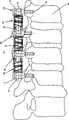
Fig. 1 is by an embodiment who is used to stablize a plurality of basivertebral devices of the present invention;
Fig. 2 is by the longitudinal sectional view of the elastic device of an embodiment of apparatus of the present invention;
Fig. 3 is by the view of the elastic device of another embodiment of apparatus of the present invention;
Fig. 4 is at the spring characteristic curve with power-deflection diagram form of the elastic device of the embodiment that presses apparatus of the present invention shown in Fig. 2.
The specific embodiment
An embodiment of the device 1 that is used for stabilize adjacent vertebrae body 6 has been shown among Fig. 1.A plurality of bone anchor logs 2 that for example are configured to pedicle screw are screwed in the pedicle of vertebral arch of vertebral body to be connected 6, and its central axis 3 is arranged transverse to the spinal column longitudinal axis.The head section 4 of bone anchor log 2 is with central axis 3 coaxial arrangement of bone anchor log 2 and have the passage 7 that extends transverse to central axis 3.In these passages 7, can insert the rod coupling part 8 of elastic device 5, make and be configured to helical spring elastic device 5 here,, can and be parallel to the spinal column longitudinal axis with respect to passage 7 and move by means of being arranged on before screw 10 in the head section 4 is fixed with respect to bone anchor log 2 at it.Elastic device 5 can be axially about its longitudinal axis 12 and the distortion of elastic bending ground, makes the spring deflection s (Fig. 4) of bone anchor log 2 be parallel to longitudinal axis 25 equally.Two axially the elastic device 5 in the outside be furnished with by connector 16a, 16b embodiment illustrated in fig. 2, and intermediary elastic device 5 comprises two shaft-like, co-axial connector 16a (Fig. 2).
Figure 2 illustrates the embodiment as the elastic device 5 of helical spring 11, its spring material has one and longitudinal axis 12 orthogonal rectangular cross sections 13, and wherein cross section 13 is parallel to the height h that longitudinal axis 12 measurements have variation.The height h that the end 14,15 towards helical spring 11 of the cross section 13 by spring material increases gradually obtains equally the pitch δ of the turn that increases gradually towards the end 14,15 of helical spring 11.Among the embodiment shown here, it is constant that gap width x keeps on the whole length of helical spring 11.Helical spring 11 has and longitudinal axis 12 orthogonal circular cylindrical cross-section, and has one in the end 14,15 that two and longitudinal axis 12 intersects respectively and be used for helical spring 11 is fixed on connector 16 (Fig. 1) on the bone anchor log 2.The first connector 16a that is arranged on helical spring 11 first ends 14 is designed to and longitudinal axis 12 co-axial bars 8, and the second connector 16b that is arranged on helical spring 11 the second ends 15 is designed to sleeve 17 and comprises one and longitudinal axis 12 co-axial centre bores 18.These two connectors 16 are fixedlyed connected with helical spring 11.The pitch δ of the variation of the turn 19 by helical spring 11 has realized progressive spring characteristic curve.For the parts with rod are fixed in the centre bore 18, be provided with a hold-down screw 25, it can be screwed into one have complementary female thread 27, have in the hole 26 transverse to the axially bored line 28 of longitudinal axis 12, and this hold-down screw 25 can be pressed in (not shown) on the bar that inserts in the centre bore 18 with its leading section.
Fig. 3 shows an embodiment of elastic device 5, and it comprises a spring 29, and this spring has a plurality of turns 19 that are arranged in a plane.What each all had a stand under load bending among three circles 19a, 19b, the 19c curves ring 21 and bridle 22.Here this bridle 22 is made of two projections 23 respectively, and these projections recline mutually after each circle 19 reaches the spring deflection of permission and stop the further strain of relevant circle 19.The ring 21 that curves of three turn 19a, 19b, 19c respectively has axis of bending 24a, a 24b, 24c, and wherein the length L 1 of the lever arm that influences bending in longitudinal axis 12 left sides is greater than the length L 2 of the lever arm that influences bending on longitudinal axis 12 right sides.The lever arm that replaces different length, the spring deflection s by bridle 22 permissions of each turn 19
iAlso can be different.Be similar to the embodiment shown in Fig. 2, spring 29 respectively has one to be applicable to elastic device 5 is fixed on connector 16 (Fig. 1) on the bone anchor log 2 in the end 34,35 that two and longitudinal axis 12 intersects.The first connector 16a that is arranged on spring 29 first ends 34 is designed to and longitudinal axis 12 co-axial bars 8, and the second connector 16b that is arranged on spring 29 the second ends 35 is designed to sleeve 17 and comprises one and longitudinal axis 12 co-axial centre bores 18.These two connectors 16 are fixedlyed connected with spring 29.For rod-shaped member being fixed in the centre bore 18, a hold-down screw (not shown) is set, it can be screwed into one have complementary female thread 27, have in the hole 26 transverse to the axially bored line 28 of longitudinal axis 12, and this hold-down screw can be pressed in (not shown) on the bar that inserts centre bore 18 with its leading section.
In Fig. 4 a, show spring characteristic curve 20 at the embodiment of the elastic device shown in Fig. 25 with power-deflection curve chart.This spring characteristic curve 20 all is progressive on whole spring deflection.This spring characteristic curve 20 for example can be realized by elastic device 5 being constructed with along the helical spring 11 of longitudinal axis 12 continually varying pitch δ.
Spring characteristic curve 20 shown in Fig. 4 b can be realized by elastic device 5 being constituted meander shape spring 29.Spring characteristic curve 20 by Fig. 4 b is rough, and at spring deflection s=s
1The time have a turning point, the closure of the bridle 22 that it for example can be by turn 19 realizes.
Claims (16)
1. be used for the flexibly device of stabilization of vertebral body (1), have:
A) at least two bone anchor logs (2) that respectively have a central axis (3) and a stature section (4); And
B) elastic device (5), these elastic devices have a longitudinal axis (12) and can be connected with the head section (4) of two adjacent bone grappling parts (2), make longitudinal axis (12) transverse to central axis (3); Wherein
C) described elastic device (5) has a kind of progressive spring characteristic curve (20) when being stressed load;
It is characterized in that:
D) described elastic device (5) is made by a kind of metal material; And
E) comprise turn (19), wherein at least two turns (19) have at least one different physical dimension mutually; And
F) spring characteristic curve (20) of described elastic device (5) has progressive trend continuously in power-deflection curve chart.
2. by the described device of claim 1 (1), it is characterized in that: described elastic device (5) constitutes the helical spring (11) of turn (19) the pitch δ with variation.
3. by the described device of claim 2 (1), it is characterized in that: described helical spring (11) is parallel to longitudinal axis (12) measurement and has a different gap width x at least between two adjacent coils (19).
4. by the described device of claim 2 (1), it is characterized in that: described helical spring (11) is made by a kind of spring material, being parallel to longitudinal axis (12) with the orthogonal cross section of longitudinal axis (12) (13) and measuring to have a different height h between at least two adjacent coils (19) of this spring material.
5. by the described device of claim 1 (1), it is characterized in that: described elastic device (5) constitutes planar, meander shape, as to have a plurality of turns of arranging successively along longitudinal axis (12) (19) spring (29).
6. by the described device of claim 5 (1), it is characterized in that: each turn (19) have one have an axis of bending (24) curve ring (21).
7. by the described device of claim 6 (1), it is characterized in that: the distance L between described axis of bending (24) and longitudinal axis (12) is constant in longitudinal axis (12) both sides.
8. by the described device of claim 6 (1), it is characterized in that: described at least one be arranged on the axis of bending (24a) in longitudinal axis (12) left side and the distance L 1 between the longitudinal axis (12) with described at least one to be arranged on that the axis of bending (24b) on longitudinal axis (12) right side and the distance L 2 between the longitudinal axis (12) compare be different.
9. by each described device (1) in the claim 5 to 8, it is characterized in that: each turn (19) comprises bridle (22), the spring deflection of the permission of described bridle restriction respective springs circle (19), wherein, the bridle (22) of each turn (19) comprises at least one projection (23), the spring deflection s of described projection restriction respective springs circle (19).
10. by the described device of claim 9 (1), it is characterized in that: the spring deflection s by described at least one projection (23) restriction is different at least two turns (19).
11. by each described device (1) in the claim 5 to 8, it is characterized in that: described meander shape spring (29) comprises n turn (19), and has spring rate i, wherein an i for each turn (19)
1<i
j<i
n
12. by each described device in the claim 6 to 8, it is characterized in that: at least two wall thickness that curve the spring material between the ring (21) is different.
13. by claim 1,2 or 5 described devices (1), it is characterized in that: (3,4) comprise connector (16) to described elastic device (5) in its end, and these connectors (16) are applicable to elastic device (5) is fixed on the bone anchor log (2).
14. by the described device of claim 13 (1), it is characterized in that: at least one connector (16a) is one and the co-axial bar of longitudinal axis (12) (8).
15. by the described device of claim 14 (1), it is characterized in that: at least one connector (16b) be one have one with the sleeve (17) of the co-axial centre bore of longitudinal axis (12) (18).
16. by the described device of claim 14 (1), it is characterized in that: at least one connector (16) comprises that a hinge connects.
Applications Claiming Priority (1)
| Application Number | Priority Date | Filing Date | Title |
|---|---|---|---|
| PCT/CH2003/000647 WO2005030066A1 (en) | 2003-09-29 | 2003-09-29 | Device for elastically stabilising vertebral bodies |
Publications (2)
| Publication Number | Publication Date |
|---|---|
| CN1838918A CN1838918A (en) | 2006-09-27 |
| CN100435746C true CN100435746C (en) | 2008-11-26 |
Family
ID=34383939
Family Applications (1)
| Application Number | Title | Priority Date | Filing Date |
|---|---|---|---|
| CNB038271117A Expired - Fee Related CN100435746C (en) | 2003-09-29 | 2003-09-29 | Device for elastically stabilizing vertebral bodies |
Country Status (14)
| Country | Link |
|---|---|
| US (1) | US8012178B2 (en) |
| EP (1) | EP1667591B1 (en) |
| JP (1) | JP4932254B2 (en) |
| KR (1) | KR101026942B1 (en) |
| CN (1) | CN100435746C (en) |
| AR (1) | AR045758A1 (en) |
| AT (1) | ATE434983T1 (en) |
| AU (1) | AU2003264224B2 (en) |
| BR (1) | BR0318489B1 (en) |
| CA (1) | CA2540591C (en) |
| DE (1) | DE50311676D1 (en) |
| ES (1) | ES2325989T3 (en) |
| NZ (1) | NZ546110A (en) |
| WO (1) | WO2005030066A1 (en) |
Families Citing this family (82)
| Publication number | Priority date | Publication date | Assignee | Title |
|---|---|---|---|---|
| FR2812185B1 (en) | 2000-07-25 | 2003-02-28 | Spine Next Sa | SEMI-RIGID CONNECTION PIECE FOR RACHIS STABILIZATION |
| US7833250B2 (en) | 2004-11-10 | 2010-11-16 | Jackson Roger P | Polyaxial bone screw with helically wound capture connection |
| US8876868B2 (en) | 2002-09-06 | 2014-11-04 | Roger P. Jackson | Helical guide and advancement flange with radially loaded lip |
| US7377923B2 (en) | 2003-05-22 | 2008-05-27 | Alphatec Spine, Inc. | Variable angle spinal screw assembly |
| US8366753B2 (en) | 2003-06-18 | 2013-02-05 | Jackson Roger P | Polyaxial bone screw assembly with fixed retaining structure |
| US7776067B2 (en) | 2005-05-27 | 2010-08-17 | Jackson Roger P | Polyaxial bone screw with shank articulation pressure insert and method |
| US8936623B2 (en) | 2003-06-18 | 2015-01-20 | Roger P. Jackson | Polyaxial bone screw assembly |
| US7967850B2 (en) | 2003-06-18 | 2011-06-28 | Jackson Roger P | Polyaxial bone anchor with helical capture connection, insert and dual locking assembly |
| US7766915B2 (en) | 2004-02-27 | 2010-08-03 | Jackson Roger P | Dynamic fixation assemblies with inner core and outer coil-like member |
| US7753958B2 (en) | 2003-08-05 | 2010-07-13 | Gordon Charles R | Expandable intervertebral implant |
| US7785351B2 (en) | 2003-08-05 | 2010-08-31 | Flexuspine, Inc. | Artificial functional spinal implant unit system and method for use |
| US7909869B2 (en) | 2003-08-05 | 2011-03-22 | Flexuspine, Inc. | Artificial spinal unit assemblies |
| US20050203513A1 (en) | 2003-09-24 | 2005-09-15 | Tae-Ahn Jahng | Spinal stabilization device |
| US20050065516A1 (en) | 2003-09-24 | 2005-03-24 | Tae-Ahn Jahng | Method and apparatus for flexible fixation of a spine |
| US8979900B2 (en) | 2003-09-24 | 2015-03-17 | DePuy Synthes Products, LLC | Spinal stabilization device |
| US7763052B2 (en) | 2003-12-05 | 2010-07-27 | N Spine, Inc. | Method and apparatus for flexible fixation of a spine |
| US7815665B2 (en) | 2003-09-24 | 2010-10-19 | N Spine, Inc. | Adjustable spinal stabilization system |
| DE102004048938B4 (en) | 2004-10-07 | 2015-04-02 | Synthes Gmbh | Device for the dynamic stabilization of vertebral bodies |
| US8162985B2 (en) | 2004-10-20 | 2012-04-24 | The Board Of Trustees Of The Leland Stanford Junior University | Systems and methods for posterior dynamic stabilization of the spine |
| US8025680B2 (en) | 2004-10-20 | 2011-09-27 | Exactech, Inc. | Systems and methods for posterior dynamic stabilization of the spine |
| US8226690B2 (en) | 2005-07-22 | 2012-07-24 | The Board Of Trustees Of The Leland Stanford Junior University | Systems and methods for stabilization of bone structures |
| US8267969B2 (en) | 2004-10-20 | 2012-09-18 | Exactech, Inc. | Screw systems and methods for use in stabilization of bone structures |
| US7935134B2 (en) | 2004-10-20 | 2011-05-03 | Exactech, Inc. | Systems and methods for stabilization of bone structures |
| US8926672B2 (en) | 2004-11-10 | 2015-01-06 | Roger P. Jackson | Splay control closure for open bone anchor |
| US8444681B2 (en) | 2009-06-15 | 2013-05-21 | Roger P. Jackson | Polyaxial bone anchor with pop-on shank, friction fit retainer and winged insert |
| US9168069B2 (en) | 2009-06-15 | 2015-10-27 | Roger P. Jackson | Polyaxial bone anchor with pop-on shank and winged insert with lower skirt for engaging a friction fit retainer |
| US9216041B2 (en) | 2009-06-15 | 2015-12-22 | Roger P. Jackson | Spinal connecting members with tensioned cords and rigid sleeves for engaging compression inserts |
| US9393047B2 (en) | 2009-06-15 | 2016-07-19 | Roger P. Jackson | Polyaxial bone anchor with pop-on shank and friction fit retainer with low profile edge lock |
| US7901437B2 (en) | 2007-01-26 | 2011-03-08 | Jackson Roger P | Dynamic stabilization member with molded connection |
| US7604654B2 (en) | 2005-02-22 | 2009-10-20 | Stryker Spine | Apparatus and method for dynamic vertebral stabilization |
| US20060229608A1 (en) * | 2005-03-17 | 2006-10-12 | Foster Thomas A | Apparatus and methods for spinal implant with dynamic stabilization system |
| US7828825B2 (en) | 2005-06-20 | 2010-11-09 | Warsaw Orthopedic, Inc. | Multi-level multi-functional spinal stabilization systems and methods |
| US8523865B2 (en) | 2005-07-22 | 2013-09-03 | Exactech, Inc. | Tissue splitter |
| US8105368B2 (en) | 2005-09-30 | 2012-01-31 | Jackson Roger P | Dynamic stabilization connecting member with slitted core and outer sleeve |
| US8137385B2 (en) * | 2005-10-31 | 2012-03-20 | Stryker Spine | System and method for dynamic vertebral stabilization |
| US8118869B2 (en) | 2006-03-08 | 2012-02-21 | Flexuspine, Inc. | Dynamic interbody device |
| WO2008003047A2 (en) | 2006-06-28 | 2008-01-03 | Synthes (U.S.A.) | Dynamic fixation system |
| US7806913B2 (en) | 2006-08-16 | 2010-10-05 | Depuy Spine, Inc. | Modular multi-level spine stabilization system and method |
| FR2905847B1 (en) * | 2006-09-14 | 2009-03-27 | Warsaw Orthopedic Inc | ELEMENT OF A DEVICE FOR STABILIZING THE RACHIS, AND DEVICE COMPRISING A PAIR OF SUCH ELEMENTS. |
| US8096996B2 (en) | 2007-03-20 | 2012-01-17 | Exactech, Inc. | Rod reducer |
| FR2910267B1 (en) * | 2006-12-21 | 2009-01-23 | Ldr Medical Soc Par Actions Si | VERTEBRAL SUPPORT DEVICE |
| US7959677B2 (en) | 2007-01-19 | 2011-06-14 | Flexuspine, Inc. | Artificial functional spinal unit system and method for use |
| US10383660B2 (en) | 2007-05-01 | 2019-08-20 | Roger P. Jackson | Soft stabilization assemblies with pretensioned cords |
| US20080312694A1 (en) * | 2007-06-15 | 2008-12-18 | Peterman Marc M | Dynamic stabilization rod for spinal implants and methods for manufacturing the same |
| FR2917287B1 (en) * | 2007-06-15 | 2010-09-03 | Ldr Medical | INTERVERTEBRAL PROSTHESIS |
| US8157844B2 (en) | 2007-10-22 | 2012-04-17 | Flexuspine, Inc. | Dampener system for a posterior stabilization system with a variable length elongated member |
| US8267965B2 (en) | 2007-10-22 | 2012-09-18 | Flexuspine, Inc. | Spinal stabilization systems with dynamic interbody devices |
| US8182514B2 (en) | 2007-10-22 | 2012-05-22 | Flexuspine, Inc. | Dampener system for a posterior stabilization system with a fixed length elongated member |
| US8162994B2 (en) | 2007-10-22 | 2012-04-24 | Flexuspine, Inc. | Posterior stabilization system with isolated, dual dampener systems |
| US8523912B2 (en) | 2007-10-22 | 2013-09-03 | Flexuspine, Inc. | Posterior stabilization systems with shared, dual dampener systems |
| US8187330B2 (en) | 2007-10-22 | 2012-05-29 | Flexuspine, Inc. | Dampener system for a posterior stabilization system with a variable length elongated member |
| US9232968B2 (en) | 2007-12-19 | 2016-01-12 | DePuy Synthes Products, Inc. | Polymeric pedicle rods and methods of manufacturing |
| CA2739997C (en) | 2008-08-01 | 2013-08-13 | Roger P. Jackson | Longitudinal connecting member with sleeved tensioned cords |
| EP2373236B1 (en) | 2008-12-17 | 2014-05-21 | Synthes GmbH | Posterior spine dynamic stabilizer |
| US8641734B2 (en) | 2009-02-13 | 2014-02-04 | DePuy Synthes Products, LLC | Dual spring posterior dynamic stabilization device with elongation limiting elastomers |
| US8998959B2 (en) | 2009-06-15 | 2015-04-07 | Roger P Jackson | Polyaxial bone anchors with pop-on shank, fully constrained friction fit retainer and lock and release insert |
| CN103826560A (en) | 2009-06-15 | 2014-05-28 | 罗杰.P.杰克逊 | Polyaxial bone anchor with pop-on shank and winged insert with friction fit compressive collet |
| US11229457B2 (en) | 2009-06-15 | 2022-01-25 | Roger P. Jackson | Pivotal bone anchor assembly with insert tool deployment |
| US9668771B2 (en) | 2009-06-15 | 2017-06-06 | Roger P Jackson | Soft stabilization assemblies with off-set connector |
| US9320543B2 (en) | 2009-06-25 | 2016-04-26 | DePuy Synthes Products, Inc. | Posterior dynamic stabilization device having a mobile anchor |
| US8657856B2 (en) * | 2009-08-28 | 2014-02-25 | Pioneer Surgical Technology, Inc. | Size transition spinal rod |
| US9445844B2 (en) | 2010-03-24 | 2016-09-20 | DePuy Synthes Products, Inc. | Composite material posterior dynamic stabilization spring rod |
| CN103040510B (en) * | 2011-02-17 | 2015-01-21 | 上海微创骨科医疗科技有限公司 | Dynamic spine connecting rod |
| US8388687B2 (en) | 2011-03-25 | 2013-03-05 | Flexuspine, Inc. | Interbody device insertion systems and methods |
| US9526627B2 (en) | 2011-11-17 | 2016-12-27 | Exactech, Inc. | Expandable interbody device system and method |
| CN103356275B (en) * | 2012-03-29 | 2016-06-01 | 董健文 | A kind of Micro-movement lumber pedicle screw elastic-fixation system |
| US10327818B2 (en) | 2012-06-18 | 2019-06-25 | Bruce Francis Hodgson | Method and apparatus for the treatment of scoliosis |
| CN102783999B (en) * | 2012-07-16 | 2015-08-26 | 顾军 | Orthopaedics inching three-dimensional external fixed support system |
| US20150305779A1 (en) * | 2012-08-21 | 2015-10-29 | Pierre M. Montavon | Spring and device for stabilizing human or animal bone |
| US8911478B2 (en) | 2012-11-21 | 2014-12-16 | Roger P. Jackson | Splay control closure for open bone anchor |
| TWM456793U (en) * | 2013-01-11 | 2013-07-11 | Paonan Biotech Co Ltd | Coil rod member for linking with spine connecting device |
| US10058354B2 (en) | 2013-01-28 | 2018-08-28 | Roger P. Jackson | Pivotal bone anchor assembly with frictional shank head seating surfaces |
| US8852239B2 (en) | 2013-02-15 | 2014-10-07 | Roger P Jackson | Sagittal angle screw with integral shank and receiver |
| US9492288B2 (en) | 2013-02-20 | 2016-11-15 | Flexuspine, Inc. | Expandable fusion device for positioning between adjacent vertebral bodies |
| US9566092B2 (en) | 2013-10-29 | 2017-02-14 | Roger P. Jackson | Cervical bone anchor with collet retainer and outer locking sleeve |
| US9717533B2 (en) | 2013-12-12 | 2017-08-01 | Roger P. Jackson | Bone anchor closure pivot-splay control flange form guide and advancement structure |
| US9451993B2 (en) | 2014-01-09 | 2016-09-27 | Roger P. Jackson | Bi-radial pop-on cervical bone anchor |
| US9517144B2 (en) | 2014-04-24 | 2016-12-13 | Exactech, Inc. | Limited profile intervertebral implant with incorporated fastening mechanism |
| US10398565B2 (en) | 2014-04-24 | 2019-09-03 | Choice Spine, Llc | Limited profile intervertebral implant with incorporated fastening and locking mechanism |
| US10064658B2 (en) | 2014-06-04 | 2018-09-04 | Roger P. Jackson | Polyaxial bone anchor with insert guides |
| US9597119B2 (en) | 2014-06-04 | 2017-03-21 | Roger P. Jackson | Polyaxial bone anchor with polymer sleeve |
| US11583318B2 (en) | 2018-12-21 | 2023-02-21 | Paradigm Spine, Llc | Modular spine stabilization system and associated instruments |
Citations (7)
| Publication number | Priority date | Publication date | Assignee | Title |
|---|---|---|---|---|
| EP0667127A1 (en) * | 1994-02-10 | 1995-08-16 | Acromed B.V. | Device for implantation for the purpose of limiting the movements between two vertebrae |
| US6206882B1 (en) * | 1999-03-30 | 2001-03-27 | Surgical Dynamics Inc. | Plating system for the spine |
| US6267764B1 (en) * | 1996-11-15 | 2001-07-31 | Stryker France S.A. | Osteosynthesis system with elastic deformation for spinal column |
| US6440169B1 (en) * | 1998-02-10 | 2002-08-27 | Dimso | Interspinous stabilizer to be fixed to spinous processes of two vertebrae |
| CN2529612Y (en) * | 2002-02-25 | 2003-01-08 | 谭明生 | Elastic artificial joint system of spinal column |
| GB2382304A (en) * | 2001-10-10 | 2003-05-28 | Dilip Kumar Sengupta | An assembly for soft stabilisation of vertebral bodies of the spine |
| WO2003047442A1 (en) * | 2001-12-07 | 2003-06-12 | Mathys Medizinaltechnik Ag | Damping element and device for stabilisation of adjacent vertebral bodies |
Family Cites Families (16)
| Publication number | Priority date | Publication date | Assignee | Title |
|---|---|---|---|---|
| JPS5927555Y2 (en) * | 1979-11-07 | 1984-08-09 | 東洋ゴム工業株式会社 | Cylindrical anti-vibration rubber |
| JPS5671539A (en) | 1979-11-16 | 1981-06-15 | Shoji Minagawa | Inlaying method of pattern piece to metallic product |
| JPH0732242U (en) * | 1991-06-28 | 1995-06-16 | 東洋電機製造株式会社 | Unequal pitch coil spring |
| JPH0914316A (en) * | 1995-06-27 | 1997-01-14 | Ishikawajima Harima Heavy Ind Co Ltd | Coil spring for preventing horizontal deformation |
| JP2741584B2 (en) * | 1995-10-20 | 1998-04-22 | 株式会社ロバート・リード商会 | Bone fixation device |
| US5827328A (en) * | 1996-11-22 | 1998-10-27 | Buttermann; Glenn R. | Intervertebral prosthetic device |
| JPH10184750A (en) * | 1996-12-26 | 1998-07-14 | Nhk Spring Co Ltd | Compression coil spring |
| US5984925A (en) * | 1997-07-30 | 1999-11-16 | Cross Medical Products, Inc. | Longitudinally adjustable bone plates and method for use thereof |
| JPH11159551A (en) * | 1997-11-27 | 1999-06-15 | Tama Spring:Kk | Non-linear deformed coil spring |
| JP3055670U (en) * | 1998-07-08 | 1999-01-22 | 昇 斉藤 | Soft coil spring |
| JP2000046084A (en) * | 1998-07-27 | 2000-02-15 | Kgm:Kk | Coil spring |
| JP2000337415A (en) * | 1999-05-24 | 2000-12-05 | Tama Spring:Kk | Nonlinear deformed coil spring and manufacture thereof |
| US6293949B1 (en) * | 2000-03-01 | 2001-09-25 | Sdgi Holdings, Inc. | Superelastic spinal stabilization system and method |
| FR2819169A1 (en) * | 2001-01-09 | 2002-07-12 | Brice Edouard | OSTEOSYNTHESIS DEVICE FOR SPINE |
| US6966910B2 (en) * | 2002-04-05 | 2005-11-22 | Stephen Ritland | Dynamic fixation device and method of use |
| US20030220643A1 (en) * | 2002-05-24 | 2003-11-27 | Ferree Bret A. | Devices to prevent spinal extension |
-
2003
- 2003-09-29 AT AT03818769T patent/ATE434983T1/en not_active IP Right Cessation
- 2003-09-29 CN CNB038271117A patent/CN100435746C/en not_active Expired - Fee Related
- 2003-09-29 KR KR1020067006061A patent/KR101026942B1/en not_active IP Right Cessation
- 2003-09-29 BR BRPI0318489-7A patent/BR0318489B1/en not_active IP Right Cessation
- 2003-09-29 ES ES03818769T patent/ES2325989T3/en not_active Expired - Lifetime
- 2003-09-29 JP JP2005509124A patent/JP4932254B2/en not_active Expired - Fee Related
- 2003-09-29 CA CA2540591A patent/CA2540591C/en not_active Expired - Fee Related
- 2003-09-29 EP EP03818769A patent/EP1667591B1/en not_active Expired - Lifetime
- 2003-09-29 AU AU2003264224A patent/AU2003264224B2/en not_active Ceased
- 2003-09-29 WO PCT/CH2003/000647 patent/WO2005030066A1/en active Application Filing
- 2003-09-29 DE DE50311676T patent/DE50311676D1/en not_active Expired - Lifetime
- 2003-09-29 NZ NZ546110A patent/NZ546110A/en unknown
-
2004
- 2004-09-17 AR ARP040103345A patent/AR045758A1/en unknown
-
2006
- 2006-03-29 US US11/393,567 patent/US8012178B2/en active Active
Patent Citations (7)
| Publication number | Priority date | Publication date | Assignee | Title |
|---|---|---|---|---|
| EP0667127A1 (en) * | 1994-02-10 | 1995-08-16 | Acromed B.V. | Device for implantation for the purpose of limiting the movements between two vertebrae |
| US6267764B1 (en) * | 1996-11-15 | 2001-07-31 | Stryker France S.A. | Osteosynthesis system with elastic deformation for spinal column |
| US6440169B1 (en) * | 1998-02-10 | 2002-08-27 | Dimso | Interspinous stabilizer to be fixed to spinous processes of two vertebrae |
| US6206882B1 (en) * | 1999-03-30 | 2001-03-27 | Surgical Dynamics Inc. | Plating system for the spine |
| GB2382304A (en) * | 2001-10-10 | 2003-05-28 | Dilip Kumar Sengupta | An assembly for soft stabilisation of vertebral bodies of the spine |
| WO2003047442A1 (en) * | 2001-12-07 | 2003-06-12 | Mathys Medizinaltechnik Ag | Damping element and device for stabilisation of adjacent vertebral bodies |
| CN2529612Y (en) * | 2002-02-25 | 2003-01-08 | 谭明生 | Elastic artificial joint system of spinal column |
Also Published As
| Publication number | Publication date |
|---|---|
| JP2007506458A (en) | 2007-03-22 |
| JP4932254B2 (en) | 2012-05-16 |
| AU2003264224A1 (en) | 2005-04-14 |
| CA2540591A1 (en) | 2005-04-07 |
| US8012178B2 (en) | 2011-09-06 |
| EP1667591B1 (en) | 2009-07-01 |
| KR101026942B1 (en) | 2011-04-04 |
| US20060260483A1 (en) | 2006-11-23 |
| AR045758A1 (en) | 2005-11-09 |
| KR20060101461A (en) | 2006-09-25 |
| AU2003264224B2 (en) | 2008-12-04 |
| ATE434983T1 (en) | 2009-07-15 |
| CA2540591C (en) | 2011-06-28 |
| EP1667591A1 (en) | 2006-06-14 |
| BR0318489A (en) | 2006-09-12 |
| CN1838918A (en) | 2006-09-27 |
| WO2005030066A1 (en) | 2005-04-07 |
| DE50311676D1 (en) | 2009-08-13 |
| NZ546110A (en) | 2009-04-30 |
| ES2325989T3 (en) | 2009-09-28 |
| BR0318489B1 (en) | 2012-05-02 |
Similar Documents
| Publication | Publication Date | Title |
|---|---|---|
| CN100435746C (en) | Device for elastically stabilizing vertebral bodies | |
| CN101416901B (en) | Rod assembly and modular rod system for spinal stabilization | |
| EP2116205B1 (en) | Rod-shaped implant, in particular for the dynamic stabilization of the spine | |
| EP2174610B1 (en) | Elongated implant device and vertebral stabilization device | |
| CN101716096B (en) | Bone anchoring device and stabilization device for bone parts or verterae comprising such a bone anchoring device | |
| US7833256B2 (en) | Elastic element for the use in a stabilization device for bones and vertebrae and method for the manufacture of such elastic element | |
| EP2160988B1 (en) | Rod-shaped implant in particular for stabilizing the spinal column and stabilization device including such a rod-shaped implant | |
| CN1897884B (en) | Bone fixing element and stabilising device comprising one such bone fixing element | |
| AU2002242566B2 (en) | Damping element and device for stabilisation of adjacent vertebral bodies | |
| US8388658B2 (en) | Dynamic spinal stabilization assembly with sliding collars | |
| KR100766580B1 (en) | Rod-like element for application in spinal or trauma surgery, and stabilization device with such a rod-like element | |
| US8529603B2 (en) | System and method for dynamic vertebral stabilization | |
| EP1281361A1 (en) | Device to prevent intervertebral disk degeneration | |
| JP2005511133A5 (en) | ||
| US20120035662A1 (en) | Rod screw dynamic implant for stabilizing a vertebral column | |
| ZA200602370B (en) | Device for elastically stabilising vertebral bodies |
Legal Events
| Date | Code | Title | Description |
|---|---|---|---|
| C06 | Publication | ||
| PB01 | Publication | ||
| C10 | Entry into substantive examination | ||
| SE01 | Entry into force of request for substantive examination | ||
| C14 | Grant of patent or utility model | ||
| GR01 | Patent grant | ||
| CF01 | Termination of patent right due to non-payment of annual fee |
Granted publication date: 20081126 Termination date: 20150929 |
|
| EXPY | Termination of patent right or utility model |