Develop the present invention in view of above-mentioned variety of problems, its objective is that providing a kind of can store a plurality of cartridges, the automatic photography processor that can turn round for a long time unattendedly by alternative supply successively.
And then, a kind of paper feeder of automatic photography processor is provided.It can make web-like paper such as photographic paper and heat-transferring printing paper not have and to the last use up lavishly, and automatic photography processor can not stopped using yet when changing paper.
A kind of case booth of outdoor setting of automatic photography processor also is provided, it can be arranged on be subjected to periods of direct sunlight outdoor etc. desired not for the surrounding environment domination, be not subjected to the harmful effect of its generation.
A kind of camera mechanism of subject of automatic photographing device is provided in addition, and it makes actor or actress being shot not look up state from bottom to top with face and takes pictures and can look at camera ground straight frontal face is taken pictures, thereby obtains positive photo.
In addition, also provide a kind of automatic photography processor, it can be then and there and finishes certificate photograph at an easy rate, can provide the certificate photograph that has the cutting mark that can very balancedly carry out cutting when customer need is cut into required size to photo with cutter etc.
In order to achieve the above object of the present invention being constructed as follows effectively.That is:
The described automatic photography processor of the present invention of claim 1 is following each several part to be configured on the position of regulation constitute: image is printed on the cartridge supply unit that print portion on the printing paper can hold a plurality of cartridges and these cartridges be delivered to successively assigned position, be provided with and clamp the clamping portion of unclamping cartridge and from above-mentioned print portion, take out the cartridge that uses up, or take out cartridge and deliver to the supply unit of above-mentioned print portion and the paper feed part of paper roll automatically being carried supply from above-mentioned cartridge supply unit.
The formation of the paper feeder of the described automatic photography processor of the present invention of claim 2 is: the action of two groups of paper feeders of conversion by the forward and reverse commutation rotation that drives, carry selectively with the paper roll that each group paper feeder is supplied with.
The formation of the paper feeder that the described automatic photography of the present invention of claim 3 is handled is: two groups of clampings are set and carry the unwinding of paper roll to go out 1 pair of paper-feed roll partly, in each group, on the paper-feed roll of regulation one-way clutch is set respectively, and the paper-feed roll of regulation above-mentioned in each group can be connected on the drive unit to the interlock backward rotation, make the paper-feed roll stipulated in one group and during driven in rotation by means of rotating forward or backwards of this driving through one-way clutch, the paper-feed roll of regulation then dallies through one-way clutch in another group, carries in the face of the paper roll that drives the revolution side by means of the 1 pair of paper-feed roll that drives the revolution side.
Outdoor its formation of case booth that is provided with of described automatic photography processor of claim 4 is: in the case booth of the regulation shape of holding automatic photography processor, on the outer wall section of case booth body, lay the heat-barrier material of separated foam, on the intrinsic top of case booth circulating fan is set, the bottom is provided with air conditioner and constitutes.
The outdoor case booth that is provided with of the described automatic photography processor of the present invention of claim 5 is in the described structure of claim 4, in above-mentioned case booth body upper outside cover lamp portion is set and constitutes.
The structure of the subject camera mechanism of the described automatic photography processor of the present invention of claim 6 be with actor or actress being shot relative position at regular intervals on video camera is set, and with the rectangular direction of the optical axis of video camera on watch-dog is set, also on this optical axis, half-reflecting half mirror is set with the angle of inclination of stipulating with respect to above-mentioned video camera optical axis, on watch-dog, mirror the image that above-mentioned video camera is clapped, the image that the optical axis direction of watch-dog actor or actress's one lateral reflection being shot is made actor or actress being shot judge on the watch-dog to be mirrored with above-mentioned half-reflecting half mirror simultaneously, and make above-mentioned video camera optical axis and watch-dog optical axis center that camera position is set with staggering inconsistently on half-reflecting half mirror.
The structure of the subject camera mechanism that the described automatic photography of the present invention of claim 7 is handled be in claim 6 structure, make video camera be arranged on watch-dog and from by half-reflecting half mirror on the staggered positions of the about 10~20mm of watch-dog optical axis center that actor or actress being shot is reflected.
The described certificate photograph that has the cutting mark of the present invention of claim 8 is the cutting mark that is provided with given size on the certificate photograph paper that can print a photo at least at its marge that is printed on the photo pattern.
The described cutting mark certificate photograph that has of the present invention of claim 9 is in the structure of claim 8, left and right sides cutting mark in the cutting mark is located at the inboard of the horizontal frame of certificate photograph pattern upper and lower, and the inboard that cutting mark up and down is arranged on vertical frame on the certificate photograph pattern left and right directions constitutes.
Described of the present invention the making in the automatic photography processor of being with cutting mark certificate photograph of claim 10 has: the reader unit that reads in image, the arithmetic unit that possesses the editing machine in the background images data that the pictorial data of being read in are transformed into the arithmetical unit of specified size and the pictorial data of being edited by arithmetical unit are edited into the cutting flag data, and the printer of printing out certificate photograph with the handled pictorial data of editing machine.
In the described automatic photography processor of the present invention of claim 1, in case detect the terminal detection signal of the cartridge colour band of printer portion, the supply unit action is taken out the cartridge that uses up by means of clamping portion from printer portion, and be transported to the position of regulation.And then supply unit is moved, simultaneously clamping portion is moved on the cartridge extracting position of cartridge supply unit.
After as previously mentioned the cartridge that uses up being taken out from printer portion, just new cartridge is delivered on the regulation position of cartridge supply unit, and taken out this cartridge with above-mentioned clamping portion from the cartridge supply unit that accommodates a plurality of cartridges.
By the action of supply unit cartridge is delivered to printer portion again, the cartridge that breaks away from clamping portion is installed in the printer portion.Cartridge installs, then mobile supply unit and clamping portion and standby on assigned position.
On the other hand, then the used paper of printer portion is discharged successively on the paper roll on the supply unit and carried supply from being installed in.
As described above,, then can turn round chronically unattendedly, make service intervals such as replenishing paper elongated if when cartridge uses up and automatically supplies with new cartridge successively, in turn supply with paper from supply unit.
In the paper feeder of the described automatic photography processor of claim 2, just change (or counter-rotating) by drive unit and make the side in 2 groups of paper feeders drive revolution, the opposing party's idle running.Be placed in so moving revolution once the paper roll of square paper feeder side thus paper feeder carry at this moment, the paper roll that is placed in another paper feeder side is then owing to the idle running of this paper feeder becomes the conveying holding state.
When a side's who carries as described above no paper roll, then make drive unit just change (or counter-rotating) by electrical control.The paper roll of the paper feeder side that is placed in the opposing party is carried by this paper feeder.During this period, then can settle new paper roll in the paper feeder side of not having paper roll.
By the action of such ground, just can be placed in 2 paper rolls in the paper feeding of automatic photography processor and alternately use, can accomplish to make device to use continuously without a break.
In addition, in the paper feeder of the described automatic photography processor of claim 3, can each the paper-feed roll interlock in 2 groups be reversed by drive actions.At this moment, the effect by means of the one-way clutch on the paper-feed roll that is located at regulation in each group makes the paper-feed roll of appointment among the side do dynamic driving rotation.The paper-feed roll of appointment then makes this paper-feed roll idle running among the opposing party under the effect that is located at the one-way clutch on this paper-feed roll.
Being placed in the sheet part that the unwinding of the paper roll of the paper-feed roll that refoulement changes one's position goes out whereby just carries between the 1 pair of paper-feed roll that is clamped in this group under the effect of appointment paper-feed roll driving force.
And when one group of side of carrying as described above becomes no paper roll state, make the drive unit counter-rotating by electrical control, appointment paper-feed roll of each group just with the direction of above-mentioned direction of rotation on rotate.Whereby, making to drive the group paper-feed roll of going up that rotates then dallies under the effect of one-way clutch.
The appointment paper-feed roll of idle running is done drive to rotate under the one-way clutch effect of being located on this paper-feed roll in another group, makes by the revolution driving that the paper in the paper roll becomes feed status in this group side from being placed in.
Because the separated foam heat-barrier material is set on the outer wall of case booth body, effect of heat insulation is improved more in the case booth of the outdoor setting of the described automatic photography processor of claim 4.And then, be provided with circulating fan in case booth upper part of body, the bottom is provided with air conditioner, makes air circulation expeditiously in the case booth of heating or refrigeration by utilizing air conditioner and circulating fan, just can prevent that ambient temperature is for the harmful effect that is located at the automatic photography processor in the case booth body.And, even thermally sensitive digital image treating apparatus also can be assembled into wherein, compare with existing apparatus and can shorten the photograph processing time greatly.
In the case booth of the outdoor setting of the described automatic photography processor of claim 5, because arranged outside cover lamp portion on case booth body top, just make case booth body top become dual structure, even the case booth is being arranged on the outdoor of periods of direct sunlight, by means of this cover lamp portion case booth body is kept out of the direct sun, can further improve effect of heat insulation.
In the subject camera mechanism of the described automatic photography processor of claim 6, because the top that the optical axis of video camera is arranged on the watch-dog optical axis center with staggering is consistent with the video camera optical axis in actor or actress being shot sight line of actor or actress being shot when sit down in the front, under this state, take pictures and just can photograph from the front of actor or actress's face being shot, thereby can obtain being more suitable for doing the full face of the direct-view state that various certificate photographs use
In the subject camera mechanism of the described automatic photography processor of claim 7, since make video camera near watch-dog and with by half-reflecting half mirror to the watch-dog optical axis center of actor or actress being shot reflection about 10~20mm that staggers, make that the actor or actress's being shot that relative video camera is sat down sight line is consistent with the video camera optical axis, can take pictures from more high-precision front.
In addition, the described certificate photograph that has the cutting mark of the present invention of claim 8, owing to be with cutter the cutting mark that the visual marge of the certificate photograph that is printed as forms to be carried out cutting with satisfying the criteria, so can obtain the photo of desired size.
In the photo of the described band cutting of claim 9 mark, with cutter about, a left side is after carrying out cutting by standard on the cutting mark, about obtaining, the certificate photograph of the required size of symmetery unanimity.
In addition, in the described automatic photography processor of making band cutting mark photo of claim 10, the pictorial data of being read in by reader unit is calculated pictorial data that the pictorial data that becomes to be fit to preassigned passport size utilizes editing device that this arithmetic unit is come with arithmetic unit be added at visual marge and have on the background images data of cutting flag data and form the print pictorial data, utilize this print to be printed by printer as the sheet spare photographed image of being with the cutting mark then with pictorial data.
Below, according to Fig. 1~Figure 36 embodiments of the invention 1~embodiment 5 is described respectively.And then the symbol among each figure is given independently numbering (1,2,3 in each embodiment ...).Owing to promptly use prosign its textural element in each embodiment to have different or identical situation, give explanation earlier,
(embodiment 1)
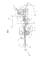
By Fig. 1~Fig. 8 embodiment 1 is described.Embodiment 1 is in the figure relevant with the described automatic photography processor of the present invention of claim 1, and this automatic photography processor 1 is to be made of printer portion 2, cartridge supply unit 3, the supply unit 5 that is provided with device folder portion 4 and sheet feed section 6 as shown in Figure 1, 2.
Printer portion 2 is provided with the color digital printer, and for example colored hot stamping camera is printed on video on the hot stamping printing paper of confessing from sheet feed section 6 by means of the colour band of cartridge A.
Cartridge supply unit 3 is made of with cartridge taking-up portion 8 cartridge storage part 7 as shown in Figure 4, and cartridge storage part 7 forms the quadrangular barrel shape, can vertically hold a plurality of cartridge A that colour band is housed.
Above-mentioned cartridge taking-up portion 8 is made of chain-linked conveyer 9 and drive unit (omitting among the figure), the chain 9a of chain-linked conveyer 9 is provided with and detects plate 10, drive chain-linked conveyer 9 as required, detect the cartridge A that plate 10 tangled and transported cartridge storage part 7 foots with this, and make this cartridge A in the place ahead of cartridge storage part 7 standby.
Whether whether the above-mentioned plate 10 that detects also is used to detect cartridge A in the place ahead of cartridge storage part 7 standby when being used to tangle cartridge A, and detect on assigned address by sensor (omitting among the figure).
Clamping portion 4 movably is located at up and down on the supply unit 5 described later, is to utilize each blade 11a, 12a being provided with on two rotating coils 11,12 shown in Fig. 5,6 to make blade 11a, the 12a rotation of being adorned on each rotating coil 11,12 (waving) and clamp the parts that unclamp above-mentioned cartridge A.In addition, also be provided with the roller 4a that the lid 2a of sealing printer portion 2 as hereinafter described uses.
Two blade 11a, 12a link mutually, utilize right rotation moving winding 12 that blade 12a dextrad is rotated, and blade 12a are inserted among the frame portion of cartridge A.The opposing party then utilizes anticlockwise moving winding 11 that blade 11a left-hand is rotated, and inserts the tape drum clip position and maintains cartridge A from the inboard.
Supply unit 5 (referring to Fig. 1~Fig. 3), makes entire combination become the portal 5a of door shape to move upward in front and back by drive unit 13, by drive unit 14 the crossbeam 5b that clamping portion 4 is installed is moved up and down.The cartridge A that uses up can be taken out from printer portion 2 by means of this supply unit 5 and clamping portion 4, perhaps new cartridge A is installed in the printer portion 2, can also realize the on-off action of color digital printer body cap 2a.
Sheet feed section 6 can be provided with 2 paper rolls (omitting among the figure) and constitute, and the conversion of the rotating by drive unit can supply to the paper roll of above-mentioned one side in the printer portion 2 selectively.Thereby, when a side paper roll does not have paper, can be conducted to paper chronically continuously among the printer portion 2 by the paper roll of automatically supplying with the opposing party.
The 15th, transport the chute that uses up cartridge A.In addition, each component part on is provided in the housing of prescribed level compactly.
Now, according to Fig. 7 and Fig. 8 the operating state of the automatic photography processor 1 of formation in the above described manner is described.
That is, after detecting the above-mentioned terminal detecting signal of the cartridge A colour band that is installed in printer portion 2, remove the locking of the lid 2a of colored hot stamping camera, above-mentioned lid is opened by not shown rope and counterweight.
Supply unit 5 moves to (1)~(5) among the figure, in clamping portion 4 the cartridge A that uses up taken out, along (5)~(2) → and the conveying of (12) direction, locate the roll coil of strip A that use up to be sent in (12) with chute 15.
Then, supply unit 5 moves to (12) → (11) → (1) → (6) → direction, takes out new cartridge (A), delivers to (1)~(5), and is installed in the printer portion 2.Then, supply unit 5 moves along (5)~(3) → (7) → (8), and the lid 2a that the roller 4a by clamping portion 4 closes colored hot stamping camera carries out (9) → (10) simultaneously and moves.Just go up standby after the above-mentioned release at assigned address (1).
On the other hand, paper spare such as hot stamping printing paper then in turn is fed to printer portion 2 by paper roll from sheet feed section 6.
(embodiment 2)
Below, according to Fig. 9~Figure 22 one explanation embodiment 2.
Embodiment 2 is the paper feeders during the described automatic photography of the present invention of claim 2, claim 3 is handled, each figure is the figure that shows the paper feeder major part, the device that this paper feeder can send the paper tape the opposing party's paper roll to when side's paper roll does not have paper.
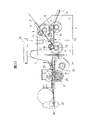
That is, to reach paper apparatus 1 be to be made of 2,3, one drive units 4 of two groups of paper feeders and other parts to as shown in Figure 9 this.Each organizes paper feeder the 2, the 3rd, is made of paper-feed roll described later and one-way clutch etc., and drive unit 4 is made of motor and a plurality of gears etc.Action by above-mentioned drive unit 4 makes paper feeder 2,3 actions, and the paper tape that unwinding from paper roll goes out is carried.
More particularly, as shown in Fig. 9~Figure 12, a pair of paper- feed roll 6,7 is horizontally set with on the top of support 5 free to rotately, and the outside of two paper-feed rolls 6,7 is the line contact.In this two paper- feed roll 6,7, be provided with one-way clutch 8 near a side's (specific) paper-feed roll 7 one ends, illustrated paper-feed roll 7 pins paper-feed roll 7 and produces driving forces and make its rotation owing to the effect of one-way clutch 8 when arrow 1 direction is rotated.And with the opposing party's paper-feed roll 6-with the side's paper roll L that regulates
1The paper tape S that (referring to Figure 12) unwinding goes out
1Then be held, and under the effect of rotating drive power, carry.
In addition, below above-mentioned paper-feed roll 7, a pair of paper- feed roll 9,10 and above-mentioned paper- feed roll 6,7 similarly are horizontally set with on support 5 free to rotately.In paper- feed roll 9,10, also be provided with one-way clutch 11 near one side's (specific) paper-feed roll 10 1 ends, when the direction of arrow of Figure 13~shown in Figure 16 is rotated, under the effect of one-way clutch 11, produce driving force and make paper-feed roll 10 revolutions, clamp the opposing party's paper roll L with paper-feed roll 9
2The paper tape S that (referring to Figure 12) unwinding goes out
2(referring to Figure 16), carry with rotary driving force.
The above-mentioned one- way clutch 8,11 of respectively organizing makes each specific give roller 7,10 idle running in the turning power reverse with driving revolution as the time spent, stops to carry the paper tape S in the supply
1, S
2
(conduct shown in and Figure 13~Figure 16) makes the above-mentioned motor 12 of respectively organizing the drive unit 4 that paper- feed roll 7,10 rotates and each gear set 13 be located at a side of support 5 as Fig. 9~Figure 12.That is, motor 12 is located at the bottom of support 5, nested gear 15 on the motor driving shaft 14.Gear 15 meshed gears 16 are nested in an end of paper-feed roll 10 therewith, then be nested on the end of paper-feed roll 7 with gear 16 meshed gears 17, because motor 12 actions are respectively organized paper- feed roll 7,10 by these gears 15,16,17 and are gone up rotation respectively in the opposite direction.
Shown in Figure 12 and 16 the 18, the 19th, angle sheave is the paper tape S that sends from two paper-feed rolls 7,10
1(or S
2) lead and deliver to the place ahead.This two angle sheave 18,19 can drive certain rotation in two paper-feed rolls 7,10 and carriage tape S
1Or S
2, also can rotate in the same direction and send paper tape S
1(or S
2).
The 20th, the band sensor is used to detect by the paper tape S of looped-shaped bending as described later after the angle sheave 18,19
1(or S
2).And before above-mentioned angle sheave 18,19, be provided with as shown in Figure 17 and detect the paper tape S that sends from two paper-feed rolls 7,10
1, S
2Glut sensor 21,22.
And, for having passed through the paper tape S of angle sheave 18,19
1(or S
2) be sent to the place ahead the driving shaft 23 relative with pressure roller 24 also is set.Driving shaft 23 links to each other with drive motor 25 by belt 26 (or chain etc.).Along with it each then make and cut and paper tape S
1(or S
2) part of joining and half lacking roller 27 and rotate of forming, to realize paper tape S
1(or S
2) conveying.28, the 29th, a pair of nip rolls, they are each paper tape S
1(or S
2) front end be clipped in and make it between roller to stop, and then the conveying of leading.
In the paper feeder 1 of the automatic photography processor of above-mentioned formation, normally the assigned position (omitting among the figure) in device is provided with 2 paper rolls respectively, as shown in Figure 17, and from side's paper roll L
1The paper tape S that (referring to Figure 12) unwinding goes out
1Insert between a pair of paper- feed roll 6,7 of support 5 tops one side and from the opposing party's paper roll L
2The paper tape S that (referring to Figure 12) unwinding goes out
2Then insert between a pair of paper- feed roll 9,10 of bottom one side.
Like this, carrying upside paper tape S
1The time, shown in arrow among Fig. 9~Figure 12, because of motor 12 drive gear 15 the direction of arrow is rotated (forward or reverse) just makes and rotate on the direction of arrow at the gear 16 of each paper-feed roll 10, the gear 17 of paper-feed roll 7.
When rotating in this wise, the one-way clutch 8 that is located on the paper-feed roll 7 of support 5 tops one side drives revolution and carriage tape S
1
On the other hand, be located at 11 idle running at this moment of one-way clutch on the paper-feed roll 10 of support 5 bottoms one side, the paper tape S of bottom one side
2Do not send to, remain holding state.
As upper side paper roll L
1During (referring to Figure 12) no paper, motor 12 automatically reverses, and 15,16,17 of each gears rotate on the direction shown in Figure 13~Figure 16 arrow.
When rotating in this wise, the one-way clutch 11 that is located on the paper-feed roll 10 of support 5 lower side drives revolution, paper tape S
2Send to.
On the other hand, the one-way clutch 8 that is located on the paper-feed roll 7 of support 5 upper side dallies at this moment, during this period, uses continuously by just making new paper roll set automatic photography processor can not shut down ground in the upper side of no paper.
Below, according to Figure 17~Figure 23 conveying upper side paper tape S is described
1Process.As shown in Figure 17, paper tape S
1, S
2Respectively from each paper roll L
1, L
2(referring to Figure 12) introduces among paper inlet X, the Y of upper side and lower side (manually), be inserted into by 21,21 detections of each glut sensor less than the position.
Preferably send upper side paper tape S by electrical control to by paper feeder 2 and drive unit 4
1, make paper tape S
1Front end arrive nip rolls 18,29 positions as shown in Figure 18.Thereafter, because paper tape S
1Continuation is from paper roll L
1(referring to Figure 12) sends and form band L between angle sheave 18,19 and driving shaft 23.
Then, become big and, stop to send into paper tape S at band L as shown in Figure 19 by the 20 detected moment of band sensor
1
As shown in figure 20, before rotating nip rolls 29, driving shaft 23 is rotated, get back to the origin-location after turning around, do just making paper tape S like this
1Be clamped between half scarce roller 27 and the pressure roller 24 and do feeding slightly, thereby reliably paper tape S
1Embed between the nip rolls 28,29.
Then, as shown in figure 21, make paper tape S
1Do to begin print after the above-mentioned action, send paper tape S to
1During this period, band L or diminish or become big.
After print finishes, as shown in figure 22, in the place ahead of nip rolls 28,29 to paper tape S
AdvanceRow is cut and is carried.At this moment, band L minimum.
After cutting finishes, as shown in figure 23, just simultaneously paper tape S
1Unload from nip rolls 28,29, at this moment, if on band sensor 20, detect less than paper tape S
1Then send into paper tape S
1 Make band sensor 20 detect paper tape S1.
Thereafter, as upper side paper roll L
1During (referring to Figure 12) no paper, then convert lower side paper roll L to
2(referring to Figure 12) repeats action carriage tape S same as described above
2Utilize the paper feeder 1 of the above embodiment of the present invention to carry hot stamping printing paper or photographic paper as described above, make it to carry out sensitization and be printed to photo by automatic photography processor.
And then paper feeder of the present invention can also use as ticket machine and cash handler's self-recorder receipt conveyor.
(embodiment 3)
Below, according to Figure 24~26 explanation embodiment 3, embodiment 3 is case booths of the outdoor setting of claim 4,5 described automatic photography processors of the present invention.
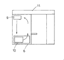
As shown in the figure, outdoor case booth 1 integral body that is provided with of automatic photography processor is rectangular shape, inside at case booth body 2 is provided with automatic photography processor 3, on the relative certain intervals position of automatic photography processor therewith 3, chair 4 is set, actor or actress being shot is sitting on the chair 4 and handles said apparatus 3 and take pictures, and just can automatically obtain photo in the short time.
The gateway 5 of coming in and going out for actor or actress being shot is set on above-mentioned case booth body 2, all the other outer peripheral faces are then held by outside wall portions 6, outside wall portions 6 is made of sheet metal 7 and separated foam heat-barrier material 8, outside wall portions 6 is all with sheet metal 7 coatings, in the inboard of outside wall portions 6, lay separated foam heat-barrier material 8 along sheet metal 7.And the gaping of joints of sheet metal 7 carries out encapsulation process.
Not mediocre theory, the top 2a of this case booth body 2 and bottom 2b also similarly constitute with above-mentioned outside wall portions 6.And with the sealing of ceiling and base plate part.
In addition, the top of automatic photography processor 3 one sides in being provided with above-mentioned case booth body 2 is provided with circulating fan 9, circulating fan 9 be provided with the position below small air-conditioning system 10 is set.Quilt with air conditioning from air conditioner 10 blows to the top, and inaccessible hot-air in case booth body 2 tops then blows to the below with circulating fan 9, and air is circulated in automatic photographing device 3, thereby best state of temperature is provided can for automatic photography processor 3.And, when digital image processing machine (not shown) is set, preferably this digital image processing machine is arranged on bottom in the lower automatic photography processor of temperature 3 in automatic photography processor 3.
Also be provided with cover lamp portion 11 in these case booth body 2 upper outside.The top area of these 11 casees booth bodies 2 of cover lamp portion is big.The plane square shape that forms the inner space is arranged, the proof utensil is set within the cover lamp portion 11 literal described and pattern on the outside 11a of cover lamp portion 11, then should occurs to bring into play the effect of publicity as much as possible.
Cover lamp portion 11 is set and makes the top of case booth body 2 become dual structure in the upper outside of case booth body 2 as described above, just can make the daylight can not be from the top direct irradiation on case booth body 2, so can further improve the effect of heat insulation of case booth body 2.
(embodiment 4)
Below, according to Figure 27~Figure 30 embodiment 4 is described.Embodiment 4 is subject camera mechanisms of the automatic photography processor of the present invention described in the claim 6,7.
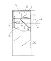
As shown in Figure 29, Figure 30, longitudinally divide the middle body of the rectangular-shaped case booth 2 that is separated with inner space 1 with demarcation strip 3, the stool of sitting for actor or actress being shot 4 is set in the 1a of a side space simultaneously.And in gateway 6 that the sidepiece setting of the above-mentioned space 1a of case booth 2 opens and closes with heavy curtain.
In the opposing party's of this case booth 2 spatial portion 16, be provided with picked-up actor or actress's video being shot subject camera mechanism A of the present invention, handle institute and take the photograph visual central processing unit (not shown) and make device such as photo device (not shown).Be sitting in actor or actress being shot on the above-mentioned stool 4 when positive (spatial portion 1b side), be provided with window 7 producing on relative demarcation strip 3 parts with its face.The shape of case booth 2 can have various variations.
The subject camera mechanism A of above-mentioned automatic photography processor is made of the aftermentioned half-reflecting half mirror 8 of the upside that is located at the 1b of upper space portion, watch-dog 10, gamma camera 12 etc.That is, with the interval of stipulating half-reflecting half mirror 8 is set with respect to above-mentioned window 7.This half-reflecting half mirror 8, as shown in figure 30, with 45 ° of pitch angle and reflecting surface 9 is provided with towards window 7 one sides ground.
Watch-dog 10 is arranged on the top of half-reflecting half mirror 8 with respect to the reflecting surface 9 of the inclination of above-mentioned half-reflecting half mirror 8 with 45 ℃ of angles.On reflecting surface 9, reflect 90 ° at the image that watch-dog 10 mirrors, make actor or actress being shot can discern its image.
At the rear of above-mentioned half-reflecting half mirror 8, the camera lens 11 of gamma camera 12 relatively is set with above-mentioned window 7.The optical axis that the installation site of gamma camera 12 should make gamma camera 12 is not provided with on half-reflecting half mirror 8 with the optical axis center 14 of above-mentioned watch-dog 10 with overlapping, makes it than the optical axis center 14 of the watch-dog 10 of giving actor or actress being shot by half-reflecting half mirror 8 reflections near about 10~20mm that staggers on watch-dog 10 directions.
Shown in Figure 27,28, owing to be provided with the optical axis 13 of gamma camera 12 than the close more top of the optical axis center 14 of watch-dog 10, the sight line that is sitting on the stool 4 actor or actress being shot under the situation of positive (window 7 one sides) actor or actress being shot is just consistent with the optical axis 13 of gamma camera 12, photograph in this state, just can take pictures from the real face of actor or actress's face being shot.In addition, because actor or actress being shot can be clapped by 8 identifications of watch-dog 10, half-reflecting half mirror the face image of oneself, and be not the face image of looking up at watch-dog 10 with the image that is mirrored, taking pictures in this state just to obtain being more suitable for the front photograph of the direct-view used in various certificates.
(embodiment 5).
Below, according to Figure 33~Figure 36 embodiment 5 is described.Embodiment 5 is certificate photograph and automatic photography processors thereof of the band cutting mark of the present invention described in the claim 8,9,10.
Figure 33 is the stereographic map that has the certificate photograph automatic photography processor of cutting mark, symbol 1 this automatic photography processor integral body of expression among the figure.
This certificate photograph automatic photography processor 1 that has the cutting mark is the inside of separating the case booth 2 that roughly forms the casing shape with demarcation strip 3, make the one side become machine chamber 4, and opposite side is photographic studio 5.
The front in photographic studio 5 has gateway 6, the front of above-mentioned demarcation strip 3 is provided with lighting device 8,9 and the coin and the paper currency inlet 10 of window 7, its upper and lower, with the window 7 on this demarcation strip 3 chair 12 and the backrest of sitting for actor or actress being shot (person of needs of certificate photograph) 11 33 is set relatively, and the operating knob (not shown).
In machine installation room 4, be provided with the video frequency camera 13 of the actor or actress being shot 11 who is sitting on the chair 12 being taken pictures by the half-reflecting half mirror (not shown).
Herein, so-called video frequency camera is meant and is provided with the gamma camera (visual reader unit) 13 that becomes the so-called CCD of electric signal with optical lens obtained image conversion in camera tube.
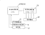
Like this, near video frequency camera 13, on the position that can see actor or actress being shot by window 7, be provided with reappear by video frequency camera 13 take the photographs to image, and to operating the Visual Display Terminal (mainly being CRT) 14 that is guided, to video frequency camera 13, the microcomputer 15 that the pictorial data of being read in is handled is arranged on the below of video frequency camera 13, is provided with below microcomputer 15 with microcomputer 15 the three primary colors YMC (Huang of the three primary colors RGB of the light in pictorial data conversion quality, product, blue or green) and print out the printer 17 of certificate photograph 16 as shown in Figure 34.
In the above-mentioned microcomputer 15, as shown in figure 35 central arithmetic processing apparatus (CPU) 21 is being set, the arithmetic processing apparatus SUB-CPU that power supply and various subsidiary engine 22 are controlled is set also) 23.Wherein central authorities fortune treating apparatus (CPU) 21 have the arithmetic unit 18 that the pictorial data of being read in by video frequency camera 13 is carried out computing and be converted to the pictorial data that is suitable for preliminary dimension, and the pictorial data from arithmetic unit 18 is attached to photo figure 20 marges has and form the editing device 19 of print with pictorial data on the background images data of cutting mark.
Below, by the process flow diagram of Figure 36 the certificate photograph automatic photography processor 1 that has the cutting mark that uses said structure is described and print out as shown in figure 34 the passport specification and visa with the program of certificate photograph 16.
At first, specify desired photo size, for example the proof photo used of passport specification and visa.Be sitting on the chair 12 towards window 7 then, starting video frequency camera 13 takes pictures for actor or actress being shot.Owing to meanwhile the image of being taken the photograph by video frequency camera 13 is reflected on VDT14 in real time as image, when this that mirrors through the half-reflecting half mirror (not shown) in identification is visual and behind the selected satisfied composition, be presented on the VDT14 as the image that fixes with selected image.
When if the image that fixes of selected image is dissatisfied, then operation deletion button (not shown) starts once more and looks gamma camera 13 and taking the photograph image is mapped on the VDT14 in real time.After having selected the satisfied image that fixes in this wise, just this image is turned into pictorial data and read in the central arithmetic processing apparatus (CPU) 21.
Then, after reading in satisfied pictorial data in the central arithmetic processing apparatus (CPU) 21, because the pictorial data of being read in is the wide 64mmX48mm of being of the long X of dimension of picture, will be with the editing device in the central arithmetic processing apparatus (CPU) 21 editing the 45mmX35mm of the passport specification that makes it to become appointment, and the pictorial data behind this editor is attached on the background images data of the data that have cutting mark 24 on four jiaos of the marges of photo figure 20.
When example of this editor is carried out in explanation, at first, be reduced into the wide 35mm of passport specification reading in width 48mm in the pictorial data that is of a size of 64mmX48mm in the central arithmetic processing apparatus (CPU) 21.
After carrying out above-mentioned dwindling, the length of pictorial data becomes 46.6mm, also will cut 0.8mm thereon down.
And to be transformed into the pictorial data of being read in the central arithmetic processing apparatus (CPU) 21 certificate photograph of visa size, carry out with above-mentioned passport size in the roughly the same computing, the editor that are carried out.
That is,, it is become the 50mmX50mm of the visa size of appointment, amplify the 50mm that becomes the visa size to the width 48mm of dimension of picture because central arithmetic processing apparatus (CPU) 21 its dimension of pictures of the pictorial data of being read in are 64mmX48mm.So, because the length of dimension of picture becomes 66.6mm, to compile with the editing device in the central calculation process (CPU) 21 it is cut 8.3mm up and down, and this editor's pictorial data is attached on four jiaos of photo image 20 marges has on the background images data of cutting mark 24.
At this, for cutting mark 24 being become close mark in target size, the length that makes on the pictorial data additional photo image 20 is with wide during than the big 1~2mm of target size, left and right sides cutting mark 24a among the cutting mark people 24 just be located at certificate photograph 16 photo image 20 top and below be positioned at the inboard of horizontal frame 20a, cutting mark 24b then is located at the inboard of vertical frame 20b of left and right side of the photo image of above-mentioned certificate photograph 16 up and down.In this case, can not switch to cutter on the separatrix of photo 20 and background images, so even cutter location slightly deflection also can not cut the image on photo four limits.
Like this, by computing, the passport size of compiling pictorial data and visa size and the three primary colors YMC of the conversion of the light three primary colors RGB in pictorial data quality, carry out print with printer 17 again, just can finish as shown in Figure 34 four jiaos of the marges of photo image 21 the photo 16a of passport size of cutting flag data 24 and the photo 16b certificate photograph 16 arranged side by side of visa size are arranged.
If the cutting mark 24 of the certificate photograph that is printed as like this 16 is satisfied the criteria, carry out cutting with the cutting knife (not shown) by it and just can obtain the balanced up and down consistent passport size and the certificate photograph of visa size.
And then, though be to be that example describes in the foregoing description 5 with the certificate photograph of making passport size and visa size, much less also can be with making the certificate photograph of other arbitrary dimension that the general certificate in the right hurdle of Figure 36 uses with the roughly the same method of the foregoing description 5.In addition, though be in the starting video frequency camera, the image of being taken the photograph by video frequency camera to be mapped on the VDT in real time in the foregoing description 5.In case the image that video frequency camera is taken the photograph record on tape or hard disk, just can make its reproduction certainly and select satisfied image.